EP2119310B1 - System and method for providing hearing assistance to a user - Google Patents
System and method for providing hearing assistance to a user Download PDFInfo
- Publication number
- EP2119310B1 EP2119310B1 EP07711370.2A EP07711370A EP2119310B1 EP 2119310 B1 EP2119310 B1 EP 2119310B1 EP 07711370 A EP07711370 A EP 07711370A EP 2119310 B1 EP2119310 B1 EP 2119310B1
- Authority
- EP
- European Patent Office
- Prior art keywords
- unit
- audio
- link
- right ear
- left ear
- Prior art date
- Legal status (The legal status is an assumption and is not a legal conclusion. Google has not performed a legal analysis and makes no representation as to the accuracy of the status listed.)
- Active
Links
- 230000013707 sensory perception of sound Effects 0.000 title claims description 70
- 238000000034 method Methods 0.000 title claims description 8
- 230000005236 sound signal Effects 0.000 claims description 83
- 230000005540 biological transmission Effects 0.000 claims description 27
- 230000004936 stimulating effect Effects 0.000 claims description 16
- 238000012545 processing Methods 0.000 claims description 9
- 239000000203 mixture Substances 0.000 claims description 4
- 230000006870 function Effects 0.000 claims description 3
- 238000005259 measurement Methods 0.000 description 3
- 238000012544 monitoring process Methods 0.000 description 3
- 238000010586 diagram Methods 0.000 description 2
- 230000007613 environmental effect Effects 0.000 description 2
- 239000013589 supplement Substances 0.000 description 2
- 206010011878 Deafness Diseases 0.000 description 1
- 208000032041 Hearing impaired Diseases 0.000 description 1
- 230000003321 amplification Effects 0.000 description 1
- 238000004458 analytical method Methods 0.000 description 1
- 230000009286 beneficial effect Effects 0.000 description 1
- 238000004891 communication Methods 0.000 description 1
- 230000001419 dependent effect Effects 0.000 description 1
- 210000005069 ears Anatomy 0.000 description 1
- 230000000694 effects Effects 0.000 description 1
- 230000004886 head movement Effects 0.000 description 1
- 230000010370 hearing loss Effects 0.000 description 1
- 231100000888 hearing loss Toxicity 0.000 description 1
- 208000016354 hearing loss disease Diseases 0.000 description 1
- 238000003199 nucleic acid amplification method Methods 0.000 description 1
Images

Classifications
-
- H—ELECTRICITY
- H04—ELECTRIC COMMUNICATION TECHNIQUE
- H04R—LOUDSPEAKERS, MICROPHONES, GRAMOPHONE PICK-UPS OR LIKE ACOUSTIC ELECTROMECHANICAL TRANSDUCERS; DEAF-AID SETS; PUBLIC ADDRESS SYSTEMS
- H04R25/00—Deaf-aid sets, i.e. electro-acoustic or electro-mechanical hearing aids; Electric tinnitus maskers providing an auditory perception
- H04R25/55—Deaf-aid sets, i.e. electro-acoustic or electro-mechanical hearing aids; Electric tinnitus maskers providing an auditory perception using an external connection, either wireless or wired
- H04R25/554—Deaf-aid sets, i.e. electro-acoustic or electro-mechanical hearing aids; Electric tinnitus maskers providing an auditory perception using an external connection, either wireless or wired using a wireless connection, e.g. between microphone and amplifier or using Tcoils
-
- H—ELECTRICITY
- H04—ELECTRIC COMMUNICATION TECHNIQUE
- H04R—LOUDSPEAKERS, MICROPHONES, GRAMOPHONE PICK-UPS OR LIKE ACOUSTIC ELECTROMECHANICAL TRANSDUCERS; DEAF-AID SETS; PUBLIC ADDRESS SYSTEMS
- H04R25/00—Deaf-aid sets, i.e. electro-acoustic or electro-mechanical hearing aids; Electric tinnitus maskers providing an auditory perception
- H04R25/40—Arrangements for obtaining a desired directivity characteristic
- H04R25/407—Circuits for combining signals of a plurality of transducers
-
- H—ELECTRICITY
- H04—ELECTRIC COMMUNICATION TECHNIQUE
- H04R—LOUDSPEAKERS, MICROPHONES, GRAMOPHONE PICK-UPS OR LIKE ACOUSTIC ELECTROMECHANICAL TRANSDUCERS; DEAF-AID SETS; PUBLIC ADDRESS SYSTEMS
- H04R25/00—Deaf-aid sets, i.e. electro-acoustic or electro-mechanical hearing aids; Electric tinnitus maskers providing an auditory perception
- H04R25/55—Deaf-aid sets, i.e. electro-acoustic or electro-mechanical hearing aids; Electric tinnitus maskers providing an auditory perception using an external connection, either wireless or wired
- H04R25/552—Binaural
-
- H—ELECTRICITY
- H04—ELECTRIC COMMUNICATION TECHNIQUE
- H04R—LOUDSPEAKERS, MICROPHONES, GRAMOPHONE PICK-UPS OR LIKE ACOUSTIC ELECTROMECHANICAL TRANSDUCERS; DEAF-AID SETS; PUBLIC ADDRESS SYSTEMS
- H04R2225/00—Details of deaf aids covered by H04R25/00, not provided for in any of its subgroups
- H04R2225/41—Detection or adaptation of hearing aid parameters or programs to listening situation, e.g. pub, forest
-
- H—ELECTRICITY
- H04—ELECTRIC COMMUNICATION TECHNIQUE
- H04R—LOUDSPEAKERS, MICROPHONES, GRAMOPHONE PICK-UPS OR LIKE ACOUSTIC ELECTROMECHANICAL TRANSDUCERS; DEAF-AID SETS; PUBLIC ADDRESS SYSTEMS
- H04R2225/00—Details of deaf aids covered by H04R25/00, not provided for in any of its subgroups
- H04R2225/55—Communication between hearing aids and external devices via a network for data exchange
-
- H—ELECTRICITY
- H04—ELECTRIC COMMUNICATION TECHNIQUE
- H04R—LOUDSPEAKERS, MICROPHONES, GRAMOPHONE PICK-UPS OR LIKE ACOUSTIC ELECTROMECHANICAL TRANSDUCERS; DEAF-AID SETS; PUBLIC ADDRESS SYSTEMS
- H04R25/00—Deaf-aid sets, i.e. electro-acoustic or electro-mechanical hearing aids; Electric tinnitus maskers providing an auditory perception
- H04R25/55—Deaf-aid sets, i.e. electro-acoustic or electro-mechanical hearing aids; Electric tinnitus maskers providing an auditory perception using an external connection, either wireless or wired
- H04R25/558—Remote control, e.g. of amplification, frequency
Definitions
- the present invention relates to a system and a method for providing hearing assistance to a user wherein audio signals from an audio signal source, which usually is a microphone arrangement, are transmitted by a transmission unit via a wireless audio link to a right ear unit and a left ear unit which are worn at or at least in part in the user's right ear and left ear, respectively, and which comprise means for stimulating the respective user's ear according to the transmitted audio signals.
- an audio signal source which usually is a microphone arrangement
- the wireless audio link is an FM (Frequency Modulation) radio link.
- FM Frequency Modulation
- the benefit of such systems is that sound captured by a remote microphone at the transmission unit can be presented at high sound pressure level to the hearing of the user wearing the ear units.
- the level of speech signals from the person using the transmission unit can be increased with regard to acoustic background noise.
- a typical application of wireless audio systems the receiver unit is connected to or integrated into a hearing instrument, such as a hearing aid.
- a hearing instrument such as a hearing aid.
- the benefit of such systems is that the microphone of the hearing instrument can be supplemented or replaced by the remote microphone which produces audio signals which are transmitted wirelessly to the FM receiver and thus to the hearing instrument.
- FM systems have been standard equipment for children with hearing loss in educational settings for many years. Their merit lies in the fact that a microphone placed a few inches from the mouth of a person speaking receives speech at a much higher level than one placed several feet away. This increase in speech level corresponds to an increase in signal-to-noise ratio (SNR) due to the direct wireless connection to the listener's amplification system.
- SNR signal-to-noise ratio
- the resulting improvements of signal level and SNR in the listener's ear are recognized as the primary benefits of FM radio systems, as hearing-impaired individuals are at a significant disadvantage when processing signals with a poor acoustical
- FM+M FM plus hearing instrument combination
- FM+ENV FM plus hearing instrument combination
- This operating mode allows the listener to perceive the speaker's voice from the remote microphone with a good SNR while the integrated hearing instrument microphone allows to listener to also hear environmental sounds. This allows the user/listener to hear and monitor his own voice, as well as voices of other people or environmental noise, as long as the loudness balance between the FM signal and the signal coming from the hearing instrument microphone is properly adjusted.
- An example of an FM system is found in CA 2 422 449 A1 wherein the FM receiver unit is mechanically connected to a hearing instrument.
- Such FM systems often are used in rooms. However, due to reflections in rooms the quality of the reception of the FM audio signals will vary depending upon head movement, position of the user in the room, positions and movement of other people or objects, etc. This varying quality manifests itself by a kind of a hissing noise and is especially noticeable in very small FM receivers as these receivers are built with very small antennas. These "holes" in the FM audio signal reception quality are an issue both with the current analogue FM systems as well as with the upcoming new digital systems.
- binaural hearing systems are already available, wherein there is provided a usually wireless link between the right ear hearing aid and the left ear hearing aid for exchanging data and audio signals between the hearing aids for improving binaural perception of sound.
- Examples of such binaural systems can be found in EP 1 651 005 A2 , US 2004/0037442 A1 and US 6,549,633 B1 .
- EP 1 531 650 A2 a binaural system is described wherein in addition to the binaural link a wireless audio link to a remote microphone is provided.
- a similar system is described in WO 02/074011 A2 .
- EP 1 657 958 A1 relates to a communication system comprising a plurality of hearing aids between which audio signals may be exchanged via wireless links.
- US 2005/0117764 A1 relates to a system comprising a right ear hearing aid and left ear hearing aid, each comprising a hearing coil for receiving audio signals from a telephone.
- the difference between the levels of the input signals of the two hearing devices at the hearing coils is measured and compared with a threshold value. If the difference in levels drops below or exceeds the threshold value, the respective hearing aid is switched to a telephone mode.
- US 2004/0252852 A1 relates to a binaural acoustic beam forming system comprising a right ear hearing aid and a left ear haring aid wherein the voice-to-background noise ratio of the audio signal captured by the microphone of the right ear hearing aid and the audio signal captured by the microphone of the left ear hearing aid is determined and compared and wherein these audio signals are mixed prior to being supplied to the respective loudspeaker of the hearing aids, with the mixing ratio depending on the noise power ratio, i.e. the ratio of the voice to background noise ratios of the left ear hearing aid and the right ear hearing aid, respectively.
- the noise power ratio i.e. the ratio of the voice to background noise ratios of the left ear hearing aid and the right ear hearing aid
- US 2004/0175008 A1 relates to a binaural hearing aid system, wherein at each ear audio signals are captured via two spaced-apart microphones, which audio signals undergo common signal processing in order to achieve binaural effects like beamforming.
- the hearing aids may exchange audio signals via a control unit acting as a weighting unit, which may be controlled by an auditory scene classifier.
- An acoustical signal captured by the microphones of a hearing aid masked by the user's head may be replaced by the acoustical signal as captured by the microphones of the hearing aid worn at the other ear in order to improve SNR, the HRTF should be maintained.
- US 2004/0013280 A1 relates to a binaural hearing aid system, wherein control data is exchanged between the two hearing aids via a wireless link.
- control data is exchanged between an external processor unit and the hearing aids via wireless links
- US 2006/0067550 A1 relates to a plurality of hearing aids which may exchange audio signals captured by the hearing aid microphones via wireless links between the hearing aids.
- the first object is achieved by a system as defined in claim 1 and a method as defined in claim 9, respectively.
- This solution is beneficial in that, by detecting the quality of the right ear link and the left ear link and exchanging audio signals received from the transmission unit between the right ear unit and the left ear unit in order to select, as a function of the detected qualities of the right ear link and the left ear link, as input to the stimulating means the audio signal received by the respective receiver unit directly from the transmission unit, the audio signals received via the audio signal exchange between the right ear unit and the left ear unit and/or mixtures thereof, the quality of the audio signals transmitted from the transmission unit to any of the two ear units can be optimized, since a poor transmission quality of one of the audio links can be compensated by supplying the audio signal transmitted via the audio link having the better quality to both ear units via the audio signal exchange between the ear units. In particular, it is thereby made possible to always select the presently better one of the right ear audio link and the left ear audio link as input to both
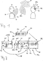
- Figs. 1 and 2 show a hearing assistance system comprising a transmission unit 10 comprising a directional microphone arrangement 12 consisting of two omnidirectional microphones M1 and M2 which are spaced apart, a right ear unit 14R and a left ear unit 14L, each comprising a receiver unit 16 and a hearing instrument 18.
- the hearing instrument 18 comprises a loudspeaker 20.
- the hearing instrument 18 and the receiver unit 16 may be connected by a mechanical/electrical interface 22 (for example, a so-called "audio shoe”), or they may be integrated into a common housing (as indicated by dashed lines in Fig. 2 ).
- the hearing aid 18 could be of any type, for example, BTE (Behind-The-Ear), ITE (In-The-Ear) or CIC (Completely-In-the-Channel).
- the transmission unit 10 may be worn by a speaker 100 around his neck by a neck loop 24 acting as an antenna, with the microphone arrangement 12 capturing the sound waves 105 carrying the speaker's voice.
- the right ear unit 14R is worn at or at least in part in the right ear 26R of the user 101
- the left ear unit 14L is worn at or at least in part in the left ear 26L of the user 101.
- background/surrounding noise 106 may be present.
- the transmission unit 10 comprises an audio signal processing unit 28 for processing the audio signals captured by the microphone arrangement 12 and a transmitter 30 for transmitting the processed audio signals via the antenna 24 via a left ear audio link 32L to the receiver unit 16 of the left ear unit 14L and via a right ear audio link 32R to the receiver unit 16 of the right ear unit 14R.
- Each receiver unit 16 comprises an antenna 34, a receiver 36 and an audio signal processing unit 38 for processing the audio signals received by the receiver 36 via the respective audio link 32R, 32L.
- Each hearing instrument 18 comprises a microphone arrangement 40 (which may comprises a single microphone or two spaced apart microphones) for capturing audio signals at the respective user's ear 26R, 26L, a central unit 42, the loudspeaker 20, a transceiver 44 and a corresponding antenna 46.
- the transceiver 44 and the antenna 46 are provided for establishing a binaural link 48 between the hearing instruments 18 of the right ear unit 14R and the left ear unit 14L, respectively, which serves to exchange audio signals and control data/commands between the right ear unit 14 R and the left ear unit 14L.
- the binaural link 48 serves to exchange audio signals received by the receiver units 16 of the right ear unit 14R and the left ear unit 14L, respectively.
- the central unit 42 serves to process the audio signals received from the built-in microphone arrangement 40, the audio signals supplied by the respective receiver unit 16 and the audio signals received by the transceiver 44 via the binaural link 48 from the hearing instrument 18 of the other one of the right ear unit 14R and the left ear unit 14L, respectively.
- the central unit 42 also serves to control the respective right ear unit 14R and left ear unit 14L.
- the processed audio signals are supplied from the central unit 42 to the speaker 20 for stimulating the respective ear 26R, 26L.
- each of the right ear unit 14R and the left ear unit 14L the quality of the respective right ear audio link 32R and the left ear audio link 32L is monitored. This can be done, for example, by a signal-to-noise- ratio (SNR) measurement of the signals received by the receiver unit 16, by an RSSI (Received Signal Strength Indication) measurement (wherein the energy integral of the signal received by the receiver unit 16 is determined) or, if the links 32R, 32L are digital, by error-rate measurements.
- SNR signal-to-noise- ratio
- RSSI Receiveived Signal Strength Indication
- Such link quality monitoring may be carried-out in the receiver unit 16 (for example, by the audio signal processing unit 38) or in the hearing instrument 18 (for example, by the central unit 42 to which the signal received by the receiver unit 16 is supplied). If the link quality is monitored in the receiver unit 16, the result of the analysis has to be supplied to the hearing instrument 18, see dashed line in Fig. 2 .
- the result of the link quality monitoring is used for improving the quality of the audio signals transmitted by the transmission unit 10 in case that one of the right ear audio link 32R and the left ear audio link 32L has a significantly lower quality than the other one.
- the audio signals received via one of the links 32R, 32L presently having the higher quality are transmitted via the binaural link 48 to the other one of the units 14R, 14L, and there they are used to replace or at least supplement the audio signals received by the receiver unit 16 of that unit 14R, 14L via that one of the links 32R, 32L presently having the lower quality, prior to being supplied as input to the respective loudspeaker 20. Consequently, both the transmission/exchange of audio signals via the binaural link 48 and the selection of the audio signals to be supplied as input to the loudspeaker 20 are controlled according to result of the monitoring of the quality of the audio links 32R, 32L.
- control can be achieved by designing the system architecture such that one of the units 14R, 14L acts as a master and the other one acts as a slave, with the necessary information regarding the quality of the respective audio link 32R, 32L being exchanged/transmitted via the binaural link 48 from the slave to the master and with corresponding control commands being transmitted via the binaural link 48 from the master to the slave.
- the selection of the audio signals which are supplied as input to the loudspeaker 20 is carried out by the central unit 42 of the hearing instrument 18 acting as the master; i.e. the decision is made by the central unit 42 of the master and corresponding control commands, if necessary, are transmitted via the binaural link 48 to the central unit 42 of the hearing instrument 18 of the other one of the units 14R, 14L.
- the binaural link 48 is established once the quality of at least one of the units 32R, 32L has been found to be below a pre-set threshold value, and the audio signals received via the better one of the links 32R, 32L is supplied via the binaural link 48 to that one of the units 14R, 14L having the worse link 32R, 32L where these audio signals are used to replace or at least supplement the audio signals received via the worse one of the links 32R, 32L.
- the audio links 32R. 32L are radio frequency links, such as an analog FM link.
- the links 32R, 32L may be digital audio links.
- the binaural link 48 preferably is a digital link, for example, a FSK (Frequency-Shift-Keying) modulated link.
- FIG. 3 An example, which does not form part of the invention, is shown in Fig. 3 , wherein only one of the ear units (for example, the left ear unit 14L) is provided with a receiver unit 16 for the audio link 32L from the transmission unit 10, whereas the other one of the ear units (in the example of Fig. 3 the right ear unit 114R) does not comprise a receiver unit for the audio signals transmitted from the transmission unit 10, so that the right ear unit 114R comprises only a hearing instrument 18.
- the audio signals received by the left ear unit 14L via the audio link 32L from the transmission unit 10 are permanently supplied via the binaural link 48 to the hearing instrument 18 of the right ear unit 114R in order to supply the audio signals transmitted by the transmission unit 10 via the link 32L and the binaural link 48 to the loudspeaker 20 of the right ear unit 114R.
- binaural hearing instruments 18 capable of establishing a binaural link 48 the need for a second receiver unit 16 for receiving audio signals directly from the transmission unit 10 is eliminated, whereby system complexity is reduced.
- the output of the receiver unit 16 may be connected to a separate high impedance audio input of the hearing instrument 18, as shown in Figs. 2 and 3 , or it may connected to a low impedance audio input of the hearing instrument 18 which is connected in parallel to the microphone 40 (see dashed lines in Figs. 2 and 3 ).
Landscapes
- Engineering & Computer Science (AREA)
- Computer Networks & Wireless Communication (AREA)
- Health & Medical Sciences (AREA)
- General Health & Medical Sciences (AREA)
- Neurosurgery (AREA)
- Otolaryngology (AREA)
- Physics & Mathematics (AREA)
- Acoustics & Sound (AREA)
- Signal Processing (AREA)
- Circuit For Audible Band Transducer (AREA)
- Headphones And Earphones (AREA)
Description
- The present invention relates to a system and a method for providing hearing assistance to a user wherein audio signals from an audio signal source, which usually is a microphone arrangement, are transmitted by a transmission unit via a wireless audio link to a right ear unit and a left ear unit which are worn at or at least in part in the user's right ear and left ear, respectively, and which comprise means for stimulating the respective user's ear according to the transmitted audio signals.
- Usually in such systems the wireless audio link is an FM (Frequency Modulation) radio link. The benefit of such systems is that sound captured by a remote microphone at the transmission unit can be presented at high sound pressure level to the hearing of the user wearing the ear units. In particular, the level of speech signals from the person using the transmission unit can be increased with regard to acoustic background noise.
- A typical application of wireless audio systems the receiver unit is connected to or integrated into a hearing instrument, such as a hearing aid. The benefit of such systems is that the microphone of the hearing instrument can be supplemented or replaced by the remote microphone which produces audio signals which are transmitted wirelessly to the FM receiver and thus to the hearing instrument. In particular, FM systems have been standard equipment for children with hearing loss in educational settings for many years. Their merit lies in the fact that a microphone placed a few inches from the mouth of a person speaking receives speech at a much higher level than one placed several feet away. This increase in speech level corresponds to an increase in signal-to-noise ratio (SNR) due to the direct wireless connection to the listener's amplification system. The resulting improvements of signal level and SNR in the listener's ear are recognized as the primary benefits of FM radio systems, as hearing-impaired individuals are at a significant disadvantage when processing signals with a poor acoustical SNR.
- Most FM systems in use today provide two or three different operating modes. The choices are to get the sound from: (1) the hearing instrument microphone alone, (2) the FM microphone alone, or (3) a combination of FM and hearing instrument microphones together.
- Usually, most of the time the FM system is used in mode (3), i.e. the FM plus hearing instrument combination (often labeled "FM+M" or "FM+ENV" mode). This operating mode allows the listener to perceive the speaker's voice from the remote microphone with a good SNR while the integrated hearing instrument microphone allows to listener to also hear environmental sounds. This allows the user/listener to hear and monitor his own voice, as well as voices of other people or environmental noise, as long as the loudness balance between the FM signal and the signal coming from the hearing instrument microphone is properly adjusted.
- An example of an FM system is found in
CA 2 422 449 A1 wherein the FM receiver unit is mechanically connected to a hearing instrument. - Such FM systems often are used in rooms. However, due to reflections in rooms the quality of the reception of the FM audio signals will vary depending upon head movement, position of the user in the room, positions and movement of other people or objects, etc. This varying quality manifests itself by a kind of a hissing noise and is especially noticeable in very small FM receivers as these receivers are built with very small antennas. These "holes" in the FM audio signal reception quality are an issue both with the current analogue FM systems as well as with the upcoming new digital systems.
- Further, binaural hearing systems are already available, wherein there is provided a usually wireless link between the right ear hearing aid and the left ear hearing aid for exchanging data and audio signals between the hearing aids for improving binaural perception of sound. Examples of such binaural systems can be found in
EP 1 651 005 A2 ,US 2004/0037442 A1 andUS 6,549,633 B1 . InEP 1 531 650 A2 a binaural system is described wherein in addition to the binaural link a wireless audio link to a remote microphone is provided. A similar system is described inWO 02/074011 A2 -
EP 1 657 958 A1 relates to a communication system comprising a plurality of hearing aids between which audio signals may be exchanged via wireless links. -
US 2005/0117764 A1 relates to a system comprising a right ear hearing aid and left ear hearing aid, each comprising a hearing coil for receiving audio signals from a telephone. The difference between the levels of the input signals of the two hearing devices at the hearing coils is measured and compared with a threshold value. If the difference in levels drops below or exceeds the threshold value, the respective hearing aid is switched to a telephone mode. -
US 2004/0252852 A1 relates to a binaural acoustic beam forming system comprising a right ear hearing aid and a left ear haring aid wherein the voice-to-background noise ratio of the audio signal captured by the microphone of the right ear hearing aid and the audio signal captured by the microphone of the left ear hearing aid is determined and compared and wherein these audio signals are mixed prior to being supplied to the respective loudspeaker of the hearing aids, with the mixing ratio depending on the noise power ratio, i.e. the ratio of the voice to background noise ratios of the left ear hearing aid and the right ear hearing aid, respectively. -
US 2004/0175008 A1 relates to a binaural hearing aid system, wherein at each ear audio signals are captured via two spaced-apart microphones, which audio signals undergo common signal processing in order to achieve binaural effects like beamforming. The hearing aids may exchange audio signals via a control unit acting as a weighting unit, which may be controlled by an auditory scene classifier. An acoustical signal captured by the microphones of a hearing aid masked by the user's head may be replaced by the acoustical signal as captured by the microphones of the hearing aid worn at the other ear in order to improve SNR, the HRTF should be maintained. -
US 2004/0013280 A1 relates to a binaural hearing aid system, wherein control data is exchanged between the two hearing aids via a wireless link. In addition, control data is exchanged between an external processor unit and the hearing aids via wireless links -
US 2006/0067550 A1 relates to a plurality of hearing aids which may exchange audio signals captured by the hearing aid microphones via wireless links between the hearing aids. - It is a first object of the invention to provide for a hearing assistance system wherein audio signals from a remote audio signal source are provided wirelessly to both ears of the user and wherein the quality of the audio signal transmission should be optimized.
- According to the invention the first object is achieved by a system as defined in claim 1 and a method as defined in claim 9, respectively. This solution is beneficial in that, by detecting the quality of the right ear link and the left ear link and exchanging audio signals received from the transmission unit between the right ear unit and the left ear unit in order to select, as a function of the detected qualities of the right ear link and the left ear link, as input to the stimulating means the audio signal received by the respective receiver unit directly from the transmission unit, the audio signals received via the audio signal exchange between the right ear unit and the left ear unit and/or mixtures thereof, the quality of the audio signals transmitted from the transmission unit to any of the two ear units can be optimized, since a poor transmission quality of one of the audio links can be compensated by supplying the audio signal transmitted via the audio link having the better quality to both ear units via the audio signal exchange between the ear units. In particular, it is thereby made possible to always select the presently better one of the right ear audio link and the left ear audio link as input to both the right ear unit and the left ear unit.
- In some cases it may be sufficient to use a mixture of the audio signals received via the right ear audio link and the left ear audio link. If both audio links have sufficient quality, no exchange of audio signals between the right ear unit and the left ear unit is necessary. However, in this case it would be possible to use only one of the two audio links and to transmit the audio signals received via this link to the other ear unit, while the other one of the audio links is turned off in order to save power.
- Preferred embodiments of the invention are defined in the dependent claims.
- Examples of the invention will be illustrated by reference to the attached drawings, wherein:
- Fig. 1
- is a schematic view of the use of a hearing assistance system according the invention;
- Fig. 2
- is a block diagram of a first embodiment of a hearing assistance system according to the invention; and
- Fig. 3
- is a block diagram of an example of a hearing assistance system which does not form part of the invention.
-
Figs. 1 and2 show a hearing assistance system comprising atransmission unit 10 comprising adirectional microphone arrangement 12 consisting of two omnidirectional microphones M1 and M2 which are spaced apart, a right ear unit 14R and a left ear unit 14L, each comprising areceiver unit 16 and ahearing instrument 18. Thehearing instrument 18 comprises aloudspeaker 20. Thehearing instrument 18 and thereceiver unit 16 may be connected by a mechanical/electrical interface 22 (for example, a so-called "audio shoe"), or they may be integrated into a common housing (as indicated by dashed lines inFig. 2 ). Thehearing aid 18 could be of any type, for example, BTE (Behind-The-Ear), ITE (In-The-Ear) or CIC (Completely-In-the-Channel). Thetransmission unit 10 may be worn by aspeaker 100 around his neck by aneck loop 24 acting as an antenna, with themicrophone arrangement 12 capturing thesound waves 105 carrying the speaker's voice. The right ear unit 14R is worn at or at least in part in theright ear 26R of theuser 101, and the left ear unit 14L is worn at or at least in part in theleft ear 26L of theuser 101. In addition to thevoice 105 of thespeaker 100 background/surroundingnoise 106 may be present. - The
transmission unit 10 comprises an audiosignal processing unit 28 for processing the audio signals captured by themicrophone arrangement 12 and atransmitter 30 for transmitting the processed audio signals via theantenna 24 via a leftear audio link 32L to thereceiver unit 16 of the left ear unit 14L and via a rightear audio link 32R to thereceiver unit 16 of the right ear unit 14R. - Each
receiver unit 16 comprises anantenna 34, areceiver 36 and an audiosignal processing unit 38 for processing the audio signals received by thereceiver 36 via therespective audio link hearing instrument 18 comprises a microphone arrangement 40 (which may comprises a single microphone or two spaced apart microphones) for capturing audio signals at the respective user'sear central unit 42, theloudspeaker 20, atransceiver 44 and acorresponding antenna 46. Thetransceiver 44 and theantenna 46 are provided for establishing abinaural link 48 between thehearing instruments 18 of the right ear unit 14R and the left ear unit 14L, respectively, which serves to exchange audio signals and control data/commands between the right ear unit 14 R and the left ear unit 14L. In particular, thebinaural link 48 serves to exchange audio signals received by thereceiver units 16 of the right ear unit 14R and the left ear unit 14L, respectively. - The
central unit 42 serves to process the audio signals received from the built-inmicrophone arrangement 40, the audio signals supplied by therespective receiver unit 16 and the audio signals received by thetransceiver 44 via thebinaural link 48 from thehearing instrument 18 of the other one of the right ear unit 14R and the left ear unit 14L, respectively. Thecentral unit 42 also serves to control the respective right ear unit 14R and left ear unit 14L. The processed audio signals are supplied from thecentral unit 42 to thespeaker 20 for stimulating therespective ear - In each of the right ear unit 14R and the left ear unit 14L the quality of the respective right
ear audio link 32R and the left earaudio link 32L is monitored. This can be done, for example, by a signal-to-noise- ratio (SNR) measurement of the signals received by thereceiver unit 16, by an RSSI (Received Signal Strength Indication) measurement (wherein the energy integral of the signal received by thereceiver unit 16 is determined) or, if thelinks central unit 42 to which the signal received by thereceiver unit 16 is supplied). If the link quality is monitored in thereceiver unit 16, the result of the analysis has to be supplied to thehearing instrument 18, see dashed line inFig. 2 . - The result of the link quality monitoring is used for improving the quality of the audio signals transmitted by the
transmission unit 10 in case that one of the rightear audio link 32R and the left earaudio link 32L has a significantly lower quality than the other one. To this end, in this case the audio signals received via one of thelinks binaural link 48 to the other one of the units 14R, 14L, and there they are used to replace or at least supplement the audio signals received by thereceiver unit 16 of that unit 14R, 14L via that one of thelinks respective loudspeaker 20. Consequently, both the transmission/exchange of audio signals via thebinaural link 48 and the selection of the audio signals to be supplied as input to theloudspeaker 20 are controlled according to result of the monitoring of the quality of theaudio links - Practically, such control can be achieved by designing the system architecture such that one of the units 14R, 14L acts as a master and the other one acts as a slave, with the necessary information regarding the quality of the
respective audio link binaural link 48 from the slave to the master and with corresponding control commands being transmitted via thebinaural link 48 from the master to the slave. - The selection of the audio signals which are supplied as input to the
loudspeaker 20 is carried out by thecentral unit 42 of thehearing instrument 18 acting as the master; i.e. the decision is made by thecentral unit 42 of the master and corresponding control commands, if necessary, are transmitted via thebinaural link 48 to thecentral unit 42 of thehearing instrument 18 of the other one of the units 14R, 14L. - According to a preferred embodiment the
binaural link 48 is established once the quality of at least one of theunits links binaural link 48 to that one of the units 14R, 14L having theworse link links - According to a modified embodiment it would be possible to turn-off the worse one of the
links links respective receiver unit 16. - Preferably the
audio links 32R. 32L are radio frequency links, such as an analog FM link. However, according to an alternative embodiment thelinks binaural link 48 preferably is a digital link, for example, a FSK (Frequency-Shift-Keying) modulated link. - An example, which does not form part of the invention, is shown in
Fig. 3 , wherein only one of the ear units (for example, the left ear unit 14L) is provided with areceiver unit 16 for theaudio link 32L from thetransmission unit 10, whereas the other one of the ear units (in the example ofFig. 3 the right ear unit 114R) does not comprise a receiver unit for the audio signals transmitted from thetransmission unit 10, so that the right ear unit 114R comprises only ahearing instrument 18. According to this example, the audio signals received by the left ear unit 14L via theaudio link 32L from thetransmission unit 10 are permanently supplied via thebinaural link 48 to thehearing instrument 18 of the right ear unit 114R in order to supply the audio signals transmitted by thetransmission unit 10 via thelink 32L and thebinaural link 48 to theloudspeaker 20 of the right ear unit 114R. Thereby forbinaural hearing instruments 18 capable of establishing abinaural link 48 the need for asecond receiver unit 16 for receiving audio signals directly from thetransmission unit 10 is eliminated, whereby system complexity is reduced. - Depending on the type of the
hearing instrument 18, the output of thereceiver unit 16 may be connected to a separate high impedance audio input of thehearing instrument 18, as shown inFigs. 2 and3 , or it may connected to a low impedance audio input of thehearing instrument 18 which is connected in parallel to the microphone 40 (see dashed lines inFigs. 2 and3 ).
Claims (12)
- A system for providing hearing assistance to a user (101), comprising:an audio signal source (12), anda transmission unit (10) for transmitting audio signals from the audio signal source via a wireless right ear audio link (32R) to a right ear unit (14R) to be worn at or at least inpart in the user's right ear (26R) and comprising a receiver unit (16) and means (20) for stimulating the user's right ear and via a wireless left ear audio link (32L) to a left earunit (14L) to be worn at or at least in part in the user's left ear (26L) and comprising a receiver unit (16) and means (20) for stimulating the user's left ear,characterized bymeans (44, 46) for exchanging audio signals received from the transmission unit between the right ear unit and the left ear unit,means (38, 42) for detecting the quality of the right ear audio link and the quality of the left ear audio link andmeans (42) for selecting, as a function of the detected qualities of the right ear audio link and the left ear audio link, as input to each of the stimulating means the audio signals received by the respective receiver unit from the transmission unit, the audio signals received via the audio signal exchanging means, and/or mixtures thereof.
- The system of claim 1, wherein the means (44, 46) for exchanging audio signals between the right ear unit (14R) and the left ear unit (14L) is a means for establishing a wireless binaural audio link (48), wherein the selecting means (42) is integrated into the right ear unit (14R) and the left ear unit (14L), wherein one of the right ear unit (14R) and the left ear unit (14L) acts as a master and the other one acts as a slave in order to select the audio signals to be provided as input to each of the stimulating means (20), wherein the right ear unit and the left ear unit comprise means (44. 46) for establishing a wireless data link (48) for transmitting information regarding the quality of the audio link (32R, 32L) from the transmission unit (10) to the slave unit (14R, 14L) from the slave unit to the master unit (14L, 14R) and for transmitting control commands from the master unit to the slave unit, and wherein the means (44, 46) for establishing said wireless binaural audio link (48) comprise the means for establishing said wireless data link.
- The system of one of the preceding claims, wherein the right ear unit (14R) and the left ear unit (14L) each is a hearing instrument into which the receiver unit (16) is integrated.
- The system of one of claims 1 and 2, wherein the right ear unit (14R) and the left ear unit (14L) each comprises a hearing instrument (18) which is connected to the receiver unit (16) for being suppliedi with the audio signals received by the receiver unit.
- The system of one of claims 3 and 4, wherein the means (44, 46) for exchanging audio signals between the right ear unit (14R) and the left ear unit (14L) is included in the hearing instruments (18).
- The system of one of claims 3 to 5, wherein the means (38) for detecting the quality of the right ear audio link (32R) and the quality of the left ear audio link (32L) is integrated into the respective receiver unit (16).
- The system of one of claims 3 to 5, wherein the means (42) for detecting the quality of the right ear audio link (32R) and the quality of the left ear audio link (32L) is integrated into the respective hearing instrument (18), and wherein each hearing instrument (18) includes said stimulating means (20), a microphone arrangement (40) for capturing audio signals and an audio signal processing unit (42) for processing the audio signals captured by the microphone arrangement, the audio signals received by the receiver unit (16) and/or the audio signals received from the other one of the right ear unit (14R) and the left ear unit (14L).
- The system of one of the preceding claims, wherein the audio signal source is a microphone arrangement (12) integrated into or connected to the transmission unit (10).
- A method of providing hearing assistance to a user (101), comprising:generating audio signals by an audio signal source (12) and transmitting said audio signals by a transmission unit (10) via a wireless right ear audio link (32R) to a right ear unit (14R) which is worn at or at least in part in the user's right ear (26R) and which comprises means (20) for stimulating the user's right ear and via a wireless left ear audio link (32L) to a left ear unit (14L) which is worn at or at least in part in the user's left ear (26L) and which comprises means (20)for stimulating the user's left ear (26L),detecting the quality of the right ear audio link and the quality of the left ear audio link,exchanging audio signals received from the transmission unit between the right ear unit and the left ear unit according to the detected quality of the right ear audio link and the detected quality of the left ear audio link,selecting, as a function of the detected qualities of the right ear audio link and the left ear audio link, as input to each of the stimulating means the audio signals received by the respective receiver unit from the transmission unit, the audio signals received from the other one of the right ear unit and the left ear unit, and/or mixtures thereof, andstimulating the user's right ear and the user's left ear according to the selected respective audio signals.
- The method of claim 9, wherein, if the quality of one of the right ear audio link (32R) and the left ear audio link (32L) is detected as being below a pre-set threshold value, the audio signals received via that one of the right ear audio link and the left ear audio link having the higher quality is supplied as input to both of the stimulating means (20), wherein the audio signals received via that one of the right ear audio link (32R) and the left ear audio link (32L) having the lower quality is prevented from being supplied as input to any of the stimulating means (20), wherein a wireless binaural audio link (48) is established between the right ear unit (14R) and the left ear unit (14L) for said exchanging of audio signals received from the transmission unit (10) between the right ear unit and the left ear unit, wherein said wireless binaural audio link (48) is digital, and wherein said wireless binaural audio link (48) is established once the quality of one of the right ear audio link (32R) and the left ear audio link (32L) is detected as being below a pre-set threshold value
- The method of one of claims 9 and 10, wherein the quality of the right ear audio link (32R) and the quality of the left ear audio link (32L) are determined by measuring a signal-to-noise ratio, an Received-Signal-Strength-Indication (RSSI) value and/or an error rate.
- The method of one of claims 9 to 11, wherein one of the right ear unit (14R) and the left ear unit (14L) acts as a master and the other one acts as a slave in order to select the audio signals to be provided as input to each of the stimulating means (20), wherein information regarding the quality of the audio link to the slave unit (14R, 14L) is transmitted from the slave unit to the master unit (14L, 14R), wherein control commands regarding said input selection of the stimulating means (20) is transmitted from the master unit to the slave unit, and wherein the right ear audio link (32R) and the left ear audio link (32L) are analog FM links or digital links.
Applications Claiming Priority (1)
| Application Number | Priority Date | Filing Date | Title |
|---|---|---|---|
| PCT/EP2007/000511 WO2008089784A1 (en) | 2007-01-22 | 2007-01-22 | System and method for providing hearing assistance to a user |
Publications (2)
| Publication Number | Publication Date |
|---|---|
| EP2119310A1 EP2119310A1 (en) | 2009-11-18 |
| EP2119310B1 true EP2119310B1 (en) | 2016-12-14 |
Family
ID=38564521
Family Applications (1)
| Application Number | Title | Priority Date | Filing Date |
|---|---|---|---|
| EP07711370.2A Active EP2119310B1 (en) | 2007-01-22 | 2007-01-22 | System and method for providing hearing assistance to a user |
Country Status (4)
| Country | Link |
|---|---|
| US (1) | US8526648B2 (en) |
| EP (1) | EP2119310B1 (en) |
| DK (1) | DK2119310T3 (en) |
| WO (1) | WO2008089784A1 (en) |
Cited By (1)
| Publication number | Priority date | Publication date | Assignee | Title |
|---|---|---|---|---|
| US11006226B2 (en) | 2017-03-28 | 2021-05-11 | Widex A/S | Binaural hearing aid system and a method of operating a binaural hearing aid system |
Families Citing this family (36)
| Publication number | Priority date | Publication date | Assignee | Title |
|---|---|---|---|---|
| US8369959B2 (en) | 2007-05-31 | 2013-02-05 | Cochlear Limited | Implantable medical device with integrated antenna system |
| US9473859B2 (en) * | 2008-12-31 | 2016-10-18 | Starkey Laboratories, Inc. | Systems and methods of telecommunication for bilateral hearing instruments |
| EP2211579B1 (en) | 2009-01-21 | 2012-07-11 | Oticon A/S | Transmit power control in low power wireless communication system |
| KR101209126B1 (en) * | 2011-06-27 | 2012-12-06 | 경북대학교 산학협력단 | Active delay method, and improving wireless binaural hearing aid using this |
| US20130013302A1 (en) | 2011-07-08 | 2013-01-10 | Roger Roberts | Audio input device |
| DK2590436T3 (en) | 2011-11-01 | 2014-06-02 | Phonak Ag | Binaural hearing device and method to operate the hearing device |
| US9319808B2 (en) * | 2012-11-19 | 2016-04-19 | Gn Resound A/S | Hearing aid having a near field resonant parasitic element |
| US9485592B2 (en) | 2012-12-04 | 2016-11-01 | Sonova Ag | Hearing instrument comprising two antennas |
| EP3031218B1 (en) | 2013-08-09 | 2017-06-28 | Sonova AG | Hearing assistance system and method |
| EP3713254A3 (en) * | 2013-11-07 | 2020-11-18 | Oticon A/s | A binaural hearing assistance system comprising two wireless interfaces |
| KR102112850B1 (en) * | 2014-01-15 | 2020-05-19 | 삼성전자주식회사 | Method and apparatus for battery balancing of hearing aid in electronic device |
| US9560437B2 (en) | 2014-04-08 | 2017-01-31 | Doppler Labs, Inc. | Time heuristic audio control |
| US9557960B2 (en) | 2014-04-08 | 2017-01-31 | Doppler Labs, Inc. | Active acoustic filter with automatic selection of filter parameters based on ambient sound |
| US9736264B2 (en) | 2014-04-08 | 2017-08-15 | Doppler Labs, Inc. | Personal audio system using processing parameters learned from user feedback |
| US9524731B2 (en) * | 2014-04-08 | 2016-12-20 | Doppler Labs, Inc. | Active acoustic filter with location-based filter characteristics |
| US9825598B2 (en) | 2014-04-08 | 2017-11-21 | Doppler Labs, Inc. | Real-time combination of ambient audio and a secondary audio source |
| EP3205119B1 (en) | 2014-09-15 | 2020-05-13 | Sonova AG | Hearing assistance system and method |
| WO2014184395A2 (en) | 2014-09-15 | 2014-11-20 | Phonak Ag | Hearing assistance system and method |
| DE102015201945A1 (en) * | 2015-02-04 | 2016-08-04 | Sivantos Pte. Ltd. | Hearing device for binaural supply and method of operation |
| US9860652B2 (en) * | 2015-03-23 | 2018-01-02 | Etymonic Design Incorporated | Test apparatus for binaurally-coupled acoustic devices |
| EP3116239B1 (en) | 2015-07-08 | 2018-10-03 | Oticon A/s | Method for selecting transmission direction in a binaural hearing aid |
| US9980189B2 (en) * | 2015-10-20 | 2018-05-22 | Bragi GmbH | Diversity bluetooth system and method |
| US9678709B1 (en) | 2015-11-25 | 2017-06-13 | Doppler Labs, Inc. | Processing sound using collective feedforward |
| WO2017088909A1 (en) * | 2015-11-24 | 2017-06-01 | Sonova Ag | Method of operating a hearing aid and hearing aid operating according to such method |
| US9703524B2 (en) | 2015-11-25 | 2017-07-11 | Doppler Labs, Inc. | Privacy protection in collective feedforward |
| US9584899B1 (en) | 2015-11-25 | 2017-02-28 | Doppler Labs, Inc. | Sharing of custom audio processing parameters |
| US11145320B2 (en) | 2015-11-25 | 2021-10-12 | Dolby Laboratories Licensing Corporation | Privacy protection in collective feedforward |
| US10853025B2 (en) | 2015-11-25 | 2020-12-01 | Dolby Laboratories Licensing Corporation | Sharing of custom audio processing parameters |
| US10251002B2 (en) * | 2016-03-21 | 2019-04-02 | Starkey Laboratories, Inc. | Noise characterization and attenuation using linear predictive coding |
| EP3799446A1 (en) * | 2016-08-29 | 2021-03-31 | Oticon A/s | Hearing aid device with speech control functionality |
| US10136229B2 (en) * | 2017-03-24 | 2018-11-20 | Cochlear Limited | Binaural segregation of wireless accessories |
| US10332538B1 (en) * | 2018-08-17 | 2019-06-25 | Apple Inc. | Method and system for speech enhancement using a remote microphone |
| US11134350B2 (en) | 2020-01-10 | 2021-09-28 | Sonova Ag | Dual wireless audio streams transmission allowing for spatial diversity or own voice pickup (OVPU) |
| US11083031B1 (en) | 2020-01-10 | 2021-08-03 | Sonova Ag | Bluetooth audio exchange with transmission diversity |
| WO2022203923A1 (en) * | 2021-03-25 | 2022-09-29 | The General Hospital Corporation | System and method for auditory mirror therapy for hearing disorders |
| EP4109928A1 (en) | 2021-06-21 | 2022-12-28 | Sonova AG | Method and system for streaming a multichannel audio signal to a binaural hearing system |
Family Cites Families (16)
| Publication number | Priority date | Publication date | Assignee | Title |
|---|---|---|---|---|
| US5721783A (en) | 1995-06-07 | 1998-02-24 | Anderson; James C. | Hearing aid with wireless remote processor |
| US5991419A (en) * | 1997-04-29 | 1999-11-23 | Beltone Electronics Corporation | Bilateral signal processing prosthesis |
| JP4542702B2 (en) * | 1998-02-18 | 2010-09-15 | ヴェーデクス・アクティーセルスカプ | Binaural digital hearing aid system |
| WO2000000001A2 (en) * | 1999-10-15 | 2000-01-06 | Phonak Ag | Binaural synchronisation |
| AU2001278418A1 (en) * | 2000-07-14 | 2002-01-30 | Gn Resound A/S | A synchronised binaural hearing system |
| US7206421B1 (en) * | 2000-07-14 | 2007-04-17 | Gn Resound North America Corporation | Hearing system beamformer |
| AU2000269773B2 (en) | 2000-09-18 | 2006-03-02 | Phonak Ag | Method for controlling a transmission system, use of this method, transmission system, receiving unit and hearing aid |
| DE10048354A1 (en) * | 2000-09-29 | 2002-05-08 | Siemens Audiologische Technik | Method for operating a hearing aid system and hearing aid system |
| JP2004530310A (en) | 2001-03-13 | 2004-09-30 | フォーナック アーゲー | Method of forming a removable mechanical and / or electrical connection, a hearing device and a hearing device system using the method |
| US20040175008A1 (en) * | 2003-03-07 | 2004-09-09 | Hans-Ueli Roeck | Method for producing control signals, method of controlling signal and a hearing device |
| DE10347212B3 (en) * | 2003-10-10 | 2005-03-24 | Siemens Audiologische Technik Gmbh | Hearing aid device for automatic switching into telephone mode has controller for switching at least one of 2 hearing aids into telephone mode if level difference falls below or rises above at least one predefined threshold value |
| EP1531650A3 (en) | 2003-11-12 | 2008-07-09 | Gennum Corporation | Hearing instrument having a wireless base unit |
| US8019386B2 (en) * | 2004-03-05 | 2011-09-13 | Etymotic Research, Inc. | Companion microphone system and method |
| DE102004047759B3 (en) * | 2004-09-30 | 2006-06-01 | Siemens Audiologische Technik Gmbh | Use of a hearing aid system with at least two hearing aids |
| EP1657958B1 (en) * | 2005-06-27 | 2012-06-13 | Phonak Ag | Communication system and hearing device |
| DK1651005T3 (en) | 2005-12-19 | 2017-07-10 | Sonova Ag | Synchronization of sound generated in binaural hearing aid system |
-
2007
- 2007-01-22 WO PCT/EP2007/000511 patent/WO2008089784A1/en active Application Filing
- 2007-01-22 US US12/523,970 patent/US8526648B2/en active Active
- 2007-01-22 DK DK07711370.2T patent/DK2119310T3/en active
- 2007-01-22 EP EP07711370.2A patent/EP2119310B1/en active Active
Non-Patent Citations (1)
| Title |
|---|
| None * |
Cited By (1)
| Publication number | Priority date | Publication date | Assignee | Title |
|---|---|---|---|---|
| US11006226B2 (en) | 2017-03-28 | 2021-05-11 | Widex A/S | Binaural hearing aid system and a method of operating a binaural hearing aid system |
Also Published As
| Publication number | Publication date |
|---|---|
| EP2119310A1 (en) | 2009-11-18 |
| US8526648B2 (en) | 2013-09-03 |
| US20100128907A1 (en) | 2010-05-27 |
| WO2008089784A1 (en) | 2008-07-31 |
| DK2119310T3 (en) | 2017-02-13 |
Similar Documents
| Publication | Publication Date | Title |
|---|---|---|
| EP2119310B1 (en) | System and method for providing hearing assistance to a user | |
| CN106231520B (en) | Peer-to-peer networked hearing system | |
| US8077892B2 (en) | Hearing assistance system including data logging capability and method of operating the same | |
| US8345900B2 (en) | Method and system for providing hearing assistance to a user | |
| CN1832636B (en) | System and method for determining directionality of sound detected by a hearing aid | |
| EP2643983B1 (en) | Hearing assistance system and method | |
| EP1627552B1 (en) | Hearing aid system, a hearing aid and a method for processing audio signals | |
| US8144903B2 (en) | Wireless communication system | |
| EP2116102B1 (en) | Wireless communication system and method | |
| US20060067550A1 (en) | Signal transmission between hearing aids | |
| CN107690117B (en) | Binaural hearing aid device | |
| US11700493B2 (en) | Hearing aid comprising a left-right location detector | |
| US20100150387A1 (en) | System and method for providing hearing assistance to a user | |
| US20100145134A1 (en) | Device for Treatment of Stuttering and Its Use | |
| US20080240477A1 (en) | Wireless multiple input hearing assist device | |
| US20120114158A1 (en) | Hearing assistance system | |
| EP2078442B1 (en) | Hearing assistance system including data logging capability and method of operating the same |
Legal Events
| Date | Code | Title | Description |
|---|---|---|---|
| PUAI | Public reference made under article 153(3) epc to a published international application that has entered the european phase |
Free format text: ORIGINAL CODE: 0009012 |
|
| 17P | Request for examination filed |
Effective date: 20090804 |
|
| AK | Designated contracting states |
Kind code of ref document: A1 Designated state(s): AT BE BG CH CY CZ DE DK EE ES FI FR GB GR HU IE IS IT LI LT LU LV MC NL PL PT RO SE SI SK TR |
|
| DAX | Request for extension of the european patent (deleted) | ||
| 17Q | First examination report despatched |
Effective date: 20150210 |
|
| RAP1 | Party data changed (applicant data changed or rights of an application transferred) |
Owner name: SONOVA AG |
|
| GRAP | Despatch of communication of intention to grant a patent |
Free format text: ORIGINAL CODE: EPIDOSNIGR1 |
|
| INTG | Intention to grant announced |
Effective date: 20160527 |
|
| RIN1 | Information on inventor provided before grant (corrected) |
Inventor name: HAENGGI, STEFAN Inventor name: CALLIAS, FRANCOIS Inventor name: DIJKSTRA, EVERT Inventor name: MARQUIS, FRANCOIS |
|
| GRAJ | Information related to disapproval of communication of intention to grant by the applicant or resumption of examination proceedings by the epo deleted |
Free format text: ORIGINAL CODE: EPIDOSDIGR1 |
|
| GRAR | Information related to intention to grant a patent recorded |
Free format text: ORIGINAL CODE: EPIDOSNIGR71 |
|
| GRAS | Grant fee paid |
Free format text: ORIGINAL CODE: EPIDOSNIGR3 |
|
| INTC | Intention to grant announced (deleted) | ||
| INTG | Intention to grant announced |
Effective date: 20161006 |
|
| GRAA | (expected) grant |
Free format text: ORIGINAL CODE: 0009210 |
|
| AK | Designated contracting states |
Kind code of ref document: B1 Designated state(s): AT BE BG CH CY CZ DE DK EE ES FI FR GB GR HU IE IS IT LI LT LU LV MC NL PL PT RO SE SI SK TR |
|
| REG | Reference to a national code |
Ref country code: GB Ref legal event code: FG4D |
|
| REG | Reference to a national code |
Ref country code: CH Ref legal event code: EP |
|
| REG | Reference to a national code |
Ref country code: IE Ref legal event code: FG4D |
|
| REG | Reference to a national code |
Ref country code: AT Ref legal event code: REF Ref document number: 854528 Country of ref document: AT Kind code of ref document: T Effective date: 20170115 |
|
| REG | Reference to a national code |
Ref country code: DE Ref legal event code: R096 Ref document number: 602007049128 Country of ref document: DE |
|
| REG | Reference to a national code |
Ref country code: DK Ref legal event code: T3 Effective date: 20170209 |
|
| PG25 | Lapsed in a contracting state [announced via postgrant information from national office to epo] |
Ref country code: LV Free format text: LAPSE BECAUSE OF FAILURE TO SUBMIT A TRANSLATION OF THE DESCRIPTION OR TO PAY THE FEE WITHIN THE PRESCRIBED TIME-LIMIT Effective date: 20161214 |
|
| REG | Reference to a national code |
Ref country code: LT Ref legal event code: MG4D |
|
| REG | Reference to a national code |
Ref country code: NL Ref legal event code: MP Effective date: 20161214 |
|
| PG25 | Lapsed in a contracting state [announced via postgrant information from national office to epo] |
Ref country code: GR Free format text: LAPSE BECAUSE OF FAILURE TO SUBMIT A TRANSLATION OF THE DESCRIPTION OR TO PAY THE FEE WITHIN THE PRESCRIBED TIME-LIMIT Effective date: 20170315 Ref country code: LT Free format text: LAPSE BECAUSE OF FAILURE TO SUBMIT A TRANSLATION OF THE DESCRIPTION OR TO PAY THE FEE WITHIN THE PRESCRIBED TIME-LIMIT Effective date: 20161214 Ref country code: SE Free format text: LAPSE BECAUSE OF FAILURE TO SUBMIT A TRANSLATION OF THE DESCRIPTION OR TO PAY THE FEE WITHIN THE PRESCRIBED TIME-LIMIT Effective date: 20161214 |
|
| REG | Reference to a national code |
Ref country code: AT Ref legal event code: MK05 Ref document number: 854528 Country of ref document: AT Kind code of ref document: T Effective date: 20161214 |
|
| PG25 | Lapsed in a contracting state [announced via postgrant information from national office to epo] |
Ref country code: BE Free format text: LAPSE BECAUSE OF NON-PAYMENT OF DUE FEES Effective date: 20170131 Ref country code: FI Free format text: LAPSE BECAUSE OF FAILURE TO SUBMIT A TRANSLATION OF THE DESCRIPTION OR TO PAY THE FEE WITHIN THE PRESCRIBED TIME-LIMIT Effective date: 20161214 |
|
| PG25 | Lapsed in a contracting state [announced via postgrant information from national office to epo] |
Ref country code: NL Free format text: LAPSE BECAUSE OF FAILURE TO SUBMIT A TRANSLATION OF THE DESCRIPTION OR TO PAY THE FEE WITHIN THE PRESCRIBED TIME-LIMIT Effective date: 20161214 |
|
| PG25 | Lapsed in a contracting state [announced via postgrant information from national office to epo] |
Ref country code: IS Free format text: LAPSE BECAUSE OF FAILURE TO SUBMIT A TRANSLATION OF THE DESCRIPTION OR TO PAY THE FEE WITHIN THE PRESCRIBED TIME-LIMIT Effective date: 20170414 Ref country code: CZ Free format text: LAPSE BECAUSE OF FAILURE TO SUBMIT A TRANSLATION OF THE DESCRIPTION OR TO PAY THE FEE WITHIN THE PRESCRIBED TIME-LIMIT Effective date: 20161214 Ref country code: EE Free format text: LAPSE BECAUSE OF FAILURE TO SUBMIT A TRANSLATION OF THE DESCRIPTION OR TO PAY THE FEE WITHIN THE PRESCRIBED TIME-LIMIT Effective date: 20161214 Ref country code: RO Free format text: LAPSE BECAUSE OF FAILURE TO SUBMIT A TRANSLATION OF THE DESCRIPTION OR TO PAY THE FEE WITHIN THE PRESCRIBED TIME-LIMIT Effective date: 20161214 Ref country code: SK Free format text: LAPSE BECAUSE OF FAILURE TO SUBMIT A TRANSLATION OF THE DESCRIPTION OR TO PAY THE FEE WITHIN THE PRESCRIBED TIME-LIMIT Effective date: 20161214 |
|
| PG25 | Lapsed in a contracting state [announced via postgrant information from national office to epo] |
Ref country code: ES Free format text: LAPSE BECAUSE OF FAILURE TO SUBMIT A TRANSLATION OF THE DESCRIPTION OR TO PAY THE FEE WITHIN THE PRESCRIBED TIME-LIMIT Effective date: 20161214 Ref country code: BE Free format text: LAPSE BECAUSE OF FAILURE TO SUBMIT A TRANSLATION OF THE DESCRIPTION OR TO PAY THE FEE WITHIN THE PRESCRIBED TIME-LIMIT Effective date: 20161214 Ref country code: AT Free format text: LAPSE BECAUSE OF FAILURE TO SUBMIT A TRANSLATION OF THE DESCRIPTION OR TO PAY THE FEE WITHIN THE PRESCRIBED TIME-LIMIT Effective date: 20161214 Ref country code: PT Free format text: LAPSE BECAUSE OF FAILURE TO SUBMIT A TRANSLATION OF THE DESCRIPTION OR TO PAY THE FEE WITHIN THE PRESCRIBED TIME-LIMIT Effective date: 20170414 Ref country code: PL Free format text: LAPSE BECAUSE OF FAILURE TO SUBMIT A TRANSLATION OF THE DESCRIPTION OR TO PAY THE FEE WITHIN THE PRESCRIBED TIME-LIMIT Effective date: 20161214 Ref country code: IT Free format text: LAPSE BECAUSE OF FAILURE TO SUBMIT A TRANSLATION OF THE DESCRIPTION OR TO PAY THE FEE WITHIN THE PRESCRIBED TIME-LIMIT Effective date: 20161214 Ref country code: BG Free format text: LAPSE BECAUSE OF FAILURE TO SUBMIT A TRANSLATION OF THE DESCRIPTION OR TO PAY THE FEE WITHIN THE PRESCRIBED TIME-LIMIT Effective date: 20170314 |
|
| REG | Reference to a national code |
Ref country code: CH Ref legal event code: PL |
|
| REG | Reference to a national code |
Ref country code: DE Ref legal event code: R097 Ref document number: 602007049128 Country of ref document: DE |
|
| PG25 | Lapsed in a contracting state [announced via postgrant information from national office to epo] |
Ref country code: MC Free format text: LAPSE BECAUSE OF FAILURE TO SUBMIT A TRANSLATION OF THE DESCRIPTION OR TO PAY THE FEE WITHIN THE PRESCRIBED TIME-LIMIT Effective date: 20161214 |
|
| PLBE | No opposition filed within time limit |
Free format text: ORIGINAL CODE: 0009261 |
|
| STAA | Information on the status of an ep patent application or granted ep patent |
Free format text: STATUS: NO OPPOSITION FILED WITHIN TIME LIMIT |
|
| REG | Reference to a national code |
Ref country code: FR Ref legal event code: ST Effective date: 20170929 |
|
| PG25 | Lapsed in a contracting state [announced via postgrant information from national office to epo] |
Ref country code: CH Free format text: LAPSE BECAUSE OF NON-PAYMENT OF DUE FEES Effective date: 20170131 Ref country code: LI Free format text: LAPSE BECAUSE OF NON-PAYMENT OF DUE FEES Effective date: 20170131 Ref country code: FR Free format text: LAPSE BECAUSE OF NON-PAYMENT OF DUE FEES Effective date: 20170214 |
|
| REG | Reference to a national code |
Ref country code: IE Ref legal event code: MM4A |
|
| 26N | No opposition filed |
Effective date: 20170915 |
|
| PG25 | Lapsed in a contracting state [announced via postgrant information from national office to epo] |
Ref country code: LU Free format text: LAPSE BECAUSE OF NON-PAYMENT OF DUE FEES Effective date: 20170122 |
|
| PG25 | Lapsed in a contracting state [announced via postgrant information from national office to epo] |
Ref country code: IE Free format text: LAPSE BECAUSE OF NON-PAYMENT OF DUE FEES Effective date: 20170122 Ref country code: SI Free format text: LAPSE BECAUSE OF FAILURE TO SUBMIT A TRANSLATION OF THE DESCRIPTION OR TO PAY THE FEE WITHIN THE PRESCRIBED TIME-LIMIT Effective date: 20161214 |
|
| PG25 | Lapsed in a contracting state [announced via postgrant information from national office to epo] |
Ref country code: HU Free format text: LAPSE BECAUSE OF FAILURE TO SUBMIT A TRANSLATION OF THE DESCRIPTION OR TO PAY THE FEE WITHIN THE PRESCRIBED TIME-LIMIT; INVALID AB INITIO Effective date: 20070122 |
|
| PG25 | Lapsed in a contracting state [announced via postgrant information from national office to epo] |
Ref country code: CY Free format text: LAPSE BECAUSE OF NON-PAYMENT OF DUE FEES Effective date: 20161214 |
|
| PG25 | Lapsed in a contracting state [announced via postgrant information from national office to epo] |
Ref country code: TR Free format text: LAPSE BECAUSE OF FAILURE TO SUBMIT A TRANSLATION OF THE DESCRIPTION OR TO PAY THE FEE WITHIN THE PRESCRIBED TIME-LIMIT Effective date: 20161214 |
|
| PGFP | Annual fee paid to national office [announced via postgrant information from national office to epo] |
Ref country code: DK Payment date: 20230127 Year of fee payment: 17 |
|
| P01 | Opt-out of the competence of the unified patent court (upc) registered |
Effective date: 20230530 |
|
| PGFP | Annual fee paid to national office [announced via postgrant information from national office to epo] |
Ref country code: DE Payment date: 20240129 Year of fee payment: 18 Ref country code: GB Payment date: 20240129 Year of fee payment: 18 |