EP2117621B1 - Wick and relief valve for disposable laparscopic smoke evacuation system - Google Patents
Wick and relief valve for disposable laparscopic smoke evacuation system Download PDFInfo
- Publication number
- EP2117621B1 EP2117621B1 EP20080726317 EP08726317A EP2117621B1 EP 2117621 B1 EP2117621 B1 EP 2117621B1 EP 20080726317 EP20080726317 EP 20080726317 EP 08726317 A EP08726317 A EP 08726317A EP 2117621 B1 EP2117621 B1 EP 2117621B1
- Authority
- EP
- European Patent Office
- Prior art keywords
- inlet
- wick
- outlet
- hydrophilic
- removal apparatus
- Prior art date
- Legal status (The legal status is an assumption and is not a legal conclusion. Google has not performed a legal analysis and makes no representation as to the accuracy of the status listed.)
- Active
Links
- 239000000779 smoke Substances 0.000 title claims description 41
- 239000012530 fluid Substances 0.000 claims description 9
- 239000004372 Polyvinyl alcohol Substances 0.000 claims description 7
- 229920002451 polyvinyl alcohol Polymers 0.000 claims description 7
- 238000001914 filtration Methods 0.000 claims description 4
- 230000037361 pathway Effects 0.000 claims description 4
- 229920000742 Cotton Polymers 0.000 claims description 3
- 238000011045 prefiltration Methods 0.000 claims description 2
- 239000012535 impurity Substances 0.000 claims 1
- 239000007789 gas Substances 0.000 description 28
- 210000000683 abdominal cavity Anatomy 0.000 description 23
- 239000002699 waste material Substances 0.000 description 23
- 238000002357 laparoscopic surgery Methods 0.000 description 11
- 238000000034 method Methods 0.000 description 11
- XLYOFNOQVPJJNP-UHFFFAOYSA-N water Substances O XLYOFNOQVPJJNP-UHFFFAOYSA-N 0.000 description 9
- 238000001356 surgical procedure Methods 0.000 description 8
- 239000000463 material Substances 0.000 description 6
- 239000007788 liquid Substances 0.000 description 5
- 230000000903 blocking effect Effects 0.000 description 4
- 238000013517 stratification Methods 0.000 description 4
- 210000003815 abdominal wall Anatomy 0.000 description 3
- 230000000712 assembly Effects 0.000 description 3
- 238000000429 assembly Methods 0.000 description 3
- 238000012986 modification Methods 0.000 description 3
- 230000004048 modification Effects 0.000 description 3
- 239000002245 particle Substances 0.000 description 3
- 230000003134 recirculating effect Effects 0.000 description 3
- 238000012800 visualization Methods 0.000 description 3
- OKTJSMMVPCPJKN-UHFFFAOYSA-N Carbon Chemical compound [C] OKTJSMMVPCPJKN-UHFFFAOYSA-N 0.000 description 2
- 210000001015 abdomen Anatomy 0.000 description 2
- 238000002679 ablation Methods 0.000 description 2
- 230000000694 effects Effects 0.000 description 2
- 239000003517 fume Substances 0.000 description 2
- 239000002910 solid waste Substances 0.000 description 2
- -1 vapor Substances 0.000 description 2
- 210000001835 viscera Anatomy 0.000 description 2
- 230000000007 visual effect Effects 0.000 description 2
- 230000003187 abdominal effect Effects 0.000 description 1
- 238000010521 absorption reaction Methods 0.000 description 1
- 230000001934 delay Effects 0.000 description 1
- 229920002457 flexible plastic Polymers 0.000 description 1
- 239000006260 foam Substances 0.000 description 1
- 238000005534 hematocrit Methods 0.000 description 1
- 238000012830 laparoscopic surgical procedure Methods 0.000 description 1
- 238000002350 laparotomy Methods 0.000 description 1
- 238000002430 laser surgery Methods 0.000 description 1
- 239000010808 liquid waste Substances 0.000 description 1
- 239000002184 metal Substances 0.000 description 1
- 229920003023 plastic Polymers 0.000 description 1
- 238000005086 pumping Methods 0.000 description 1
- 239000007787 solid Substances 0.000 description 1
- 239000000126 substance Substances 0.000 description 1
- 238000013022 venting Methods 0.000 description 1
Images


Classifications
-
- A—HUMAN NECESSITIES
- A61—MEDICAL OR VETERINARY SCIENCE; HYGIENE
- A61B—DIAGNOSIS; SURGERY; IDENTIFICATION
- A61B18/00—Surgical instruments, devices or methods for transferring non-mechanical forms of energy to or from the body
-
- B—PERFORMING OPERATIONS; TRANSPORTING
- B01—PHYSICAL OR CHEMICAL PROCESSES OR APPARATUS IN GENERAL
- B01D—SEPARATION
- B01D46/00—Filters or filtering processes specially modified for separating dispersed particles from gases or vapours
- B01D46/0027—Filters or filtering processes specially modified for separating dispersed particles from gases or vapours with additional separating or treating functions
- B01D46/0036—Filters or filtering processes specially modified for separating dispersed particles from gases or vapours with additional separating or treating functions by adsorption or absorption
-
- B—PERFORMING OPERATIONS; TRANSPORTING
- B01—PHYSICAL OR CHEMICAL PROCESSES OR APPARATUS IN GENERAL
- B01D—SEPARATION
- B01D46/00—Filters or filtering processes specially modified for separating dispersed particles from gases or vapours
- B01D46/10—Particle separators, e.g. dust precipitators, using filter plates, sheets or pads having plane surfaces
-
- A—HUMAN NECESSITIES
- A61—MEDICAL OR VETERINARY SCIENCE; HYGIENE
- A61B—DIAGNOSIS; SURGERY; IDENTIFICATION
- A61B2218/00—Details of surgical instruments, devices or methods for transferring non-mechanical forms of energy to or from the body
- A61B2218/001—Details of surgical instruments, devices or methods for transferring non-mechanical forms of energy to or from the body having means for irrigation and/or aspiration of substances to and/or from the surgical site
- A61B2218/007—Aspiration
- A61B2218/008—Aspiration for smoke evacuation
-
- Y—GENERAL TAGGING OF NEW TECHNOLOGICAL DEVELOPMENTS; GENERAL TAGGING OF CROSS-SECTIONAL TECHNOLOGIES SPANNING OVER SEVERAL SECTIONS OF THE IPC; TECHNICAL SUBJECTS COVERED BY FORMER USPC CROSS-REFERENCE ART COLLECTIONS [XRACs] AND DIGESTS
- Y10—TECHNICAL SUBJECTS COVERED BY FORMER USPC
- Y10T—TECHNICAL SUBJECTS COVERED BY FORMER US CLASSIFICATION
- Y10T137/00—Fluid handling
- Y10T137/8593—Systems
- Y10T137/877—With flow control means for branched passages
- Y10T137/87708—With common valve operator
Definitions
- the invention relates to surgical procedures and, more specifically, to a device for more efficiently removing surgical waste and vapor smoke-free environment within the surgical field during laparoscopy.
- Laparoscopy is a fast growing surgical modality widely used in the treatment of certain prevalent physical ailments.
- Laparoscopy entails the introduction of an endoscope, light source, and surgical instruments through ports formed in the patient's abdomen.
- the patient's abdominal cavity is inflated with a suitable gas typically CO 2 to give the surgeon additional working area and minimize obstruction.
- a suitable gas typically CO 2 to give the surgeon additional working area and minimize obstruction.
- laparoscopy avoids the risks of laparotomy, which requires the surgeon to open the abdomen and carry out the required procedure by his or her direct viewing.
- a common procedure for positioning the laparoscopic assembly in the patient's abdominal cavity includes first making an incision into the patient's abdominal wall through which a large gauge needle is inserted. A suitable gas, typically CO 2 , is then introduced into the patient's abdominal cavity through the needle. The needle is then replaced with a trocar, which is then removed leaving behind a sleeve, or cannula, through which a laparoscope is introduced into the abdominal cavity. In order to perform laser or electrosurgery one or two additional small incisions are made in the abdominal wall over the surgical site and cannula/trocar assemblies positioned accordingly. These cannula/trocar assemblies may be used for the positioning of the insufflation tube as well as any other surgical instruments that may be required for the particular laparoscopic procedure.
- a laparoscopic procedure typically requires a surgeon to employ either electrosurgery or laser surgery within the confined space of the patient's abdominal cavity. This surgery typically involves tissue burning or ablation. This tissue burning leads to the creation of smoke. Surgical smoke within the confines of a patient's abdominal cavity reduces the surgeon's view of the surgical site, increases the patient's hematocrit levels, and causes delays in the surgery while the smoke is cleared from the laparoscopic field. Efficient removal of the smoke is thus a necessity for the surgical team during the laparoscopic procedure.
- laparoscopic evacuation system Although a laparoscopic evacuation system (“lapevac system”) is effective in maintaining cavity inflation pressure, one problem that occurs during its operation is the clogging of the inlet tube and filter by solid waste, water and humidity carried out of the abdominal cavity by the incoming waste stream. Because the cavity is moist and may be heated above normal temperature by some surgical procedures such as cauterization, surgical wastes can be driven off the cavity wall and internal organs in the form of particles, vapor, and liquids from broken cells and tissues. In addition, vapors within the cavity itself can be drawn into the waste stream. Another problem that may occur during laparoscopic surgery is the insufficient removal of waste vapor from the cavity, stratification of water vapor in the cavity as well as other visualization problems.
- US 6544210 discloses the preamble of independent claim 1 and US 2005 000196 discloses a smoke removal system with a filter in the inlet means.
- an inlet means as claimed in claim 1.
- a smoke removal apparatus may comprise the inlet means.
- the smoke removal apparatus may comprise a multi-outlet valve incorporated into an outlet means.
- One object of the present invention is to reduce or eliminate blocking of the inlet means by surgical waste.
- a second object of the present invention is reduce or eliminate stratification of surgical smoke and water vapor in the abdominal cavity by supplying a venting valve on the outlet means of the surgical smoke removal device to effect quick removal of smoke and water vapor.
- Figure 1 is a schematic view of a laparoscopic smoke evacuation system of the prior art depicting the arrangement of the smoke evacuation system during laparoscopic surgery;
- Figure 2 is a top perspective view of a typical disposable laparoscopic smoke evacuation system according to an embodiment of the present invention
- Figure 3 is an exploded top perspective view of the disposable laparoscopic smoke evacuation system shown in Figure 2 ;
- Figure 3A depicts an enlarged view of the wick assembly inserted into the inlet tube of the smoke evacuation system
- Figure 4 is a top perspective view depicting the components of the wick assembly in an assembled condition
- Figure 4A is a top perspective view of a partially disassembled wick assembly
- Figure 4B is a side view of the assembled wick assembly
- Figure 5 is a side view of the wick component of the wick assembly ;
- Figure 5A is an end view showing the wick depicted in Figure 4 ;
- Figure 5B is an isometric view of the wick shown in Figure 4 ;
- Figure 6A is an isometric view of one embodiment of the two-way valve in the divert mode
- Figure 6B is a top view of the two way outlet valve in the divert mode
- Figure 6C is a side view of the two-way outlet valve from the side facing the outlet port in the divert mode
- Figure 6D is a cross section of the two-way valve taken along line H-H in Figure 5B in the divert mode;
- Figure 7A is an isometric view of the two-way valve showing the valve barrel in the open (flow through) mode
- Figure 7B shows a top view of the two-way valve in the open mode
- Figure 7C is a side view of the two-way valve in the open mode facing the side of the outlet showing the open channel to the valve outlet;
- Figure 7D is a cross section of the two-way valve taken along line I-I in Figure 6B showing the channel configuration when the valve is in the open mode;
- Figure 8A is a top view of a second embodiment of the two-way outlet divert valve in the off mode
- Figure 8B is a top view of the second embodiment of the two-way outlet valve in the open mode.
- Figure 8C is a top view of the second embodiment of the two-way outlet valve in the divert mode.
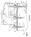
- FIG. 1 is a schematic view of a laparoscopic smoke evacuation system of the prior art depicting the arrangement of the smoke evacuation system during laparoscopic surgery.
- Smoke clearing device 10 includes housing 12.
- Housing 12 may be made out of a variety of materials, such as a metal or a plastic, as long as the material facilitates the device's use and is preferably disposable.
- the housing 12 preferably has a generally rectangular box shape or it may have a generally cylindrical hollow shape, preferably with rounded corners.
- the housing 12 contains an inlet port 14 at one end, i.e., on one side and an outlet port 16 at the other end, i.e., on the opposite side.
- One end of an inlet tube 18 is connected to the inlet port 14.
- outlet tube 20 is connected to the outlet port 16.
- This tubing is preferably conventional sterile flexible plastic tubing. It is envisioned that conventional Luer lock structures 22 will be used to connect the tubes 18 and 20 to the housing 12, but other locking structures could alternatively be used.
- the patient's tissue which is to be removed is shown as 26, with the surgical smoke shown and indicated as 26a, 26b, and 26c.
- Three trocars containing laparoscopic surgical instrument clusters 28, 30 and 32 extend through the patient's skin 25 into the cavity 24.
- Each instrument cluster includes a cannula/trocar for introducing the instrument into the patient's cavity and maintaining a seal to the cavity 24 to preclude gas escape from the cavity 24.
- Each cannula/trocar has a single channel or passage along its length that allows instruments to be inserted into the body while maintaining the intra-abdominal pressure created by insufflation.
- Instrument cluster 28 is a single channel instrument cluster which serves to house the laser instrument 34 and direct the laser beam to the operating site.
- An annular channel 36 around the instrument 34 within the trocar serves as an annular egress passage from near the operating site for gas to be drawn around the laser instrument 34 and out of the patient's cavity to the smoke clearing device 10 of the present invention.
- FIG. 2 is a top perspective view of a typical disposable laparoscopic smoke evacuation system 100 ("lapevac 100").
- housing 111 is shown with inlet means, in this case inlet tube 112 and outlet means, in this case outlet tube 120 attached to inlet attachment 112a and outlet attachment 120a, respectively.
- inlet tube 112 Inserted into the input end of inlet tube 112 is wick assembly 114.
- Attached to the outlet attachment 120a is the inlet of one embodiment of a multi-outlet relief valve, in this case a two-way bleed or relief valve, t-tap valve 150.
- two-way valve By two-way valve is meant a valve that has at least two outlets that allow material, such as a gas or liquid fluid, that enters the valve to be directed to one of two or more different outlet flow paths. Also seen is y-connector 124 ("connector 124") at the end of outlet tube 120. Persons of skill in the art will recognize that the two-way valves may be connected to outlet tube 120 in any convenient position within the length of outlet tube 120 and that valves having more than two outlets may also be used.
- FIG 3 is an exploded top perspective view of lapevac 100.
- Inlet hose 112 is seen attached to inlet attachment 112a.
- Inlet assembly 130 includes inlet 131 which covers the fan or pump assembly to include impeller cover 132, impeller 133, fan 134, and fan mount 134a which are all attached to motor 136.
- Battery cover 111a covers battery (ies) 138 used to power motor 136. Although a plurality of AA batteries are shown in Figure 3 , persons of skill in the art will recognize that a single battery, various appropriate battery assemblies with different capacities, or alternative ac power sources may be used to provide power to motor 136.
- Outlet 142 covers filter 140 positioned on the downstream side of fan assembly 130 .
- the filter 140 includes activated carbon media 141a as a prefilter plus ultra low particulate air (ULPA) filter 141b.
- Outlet attachment 120a extends from outlet 142 and is seen connected to t-tap valve 150.
- One end of outlet tube 120 is connected to t-tap valve 150, while the other end is connected to connector 124.
- a locking means 126 is positioned on at least one outlet of y-connector 124 to enable y-connector 124 to be securely attached to an additional component.
- the locking means 126 is a luer lock.
- Cap 127 is used to block an unused outlet of y-connector 124.
- the locking means 116 such as a luer lock, may be positioned at the input end of inlet tube 112 as shown in Figures 2 and 3 .
- Locking means utilized throughout the invention are defined as connections between two components that prevent the escape of vapor, liquid, or fumes from the connection itself. Examples of locking means are luer locks, tube connections in which one tube is inserted into another tube, interference fittings, Colder couplers and other connectors known t those skilled in the art that prevent the escape of fumes from a connection point.
- Y-connector 124 receives filtered gas from lapevac 100.
- One of the two outlets ofy-connector 124 can be connected to an insufflator while the second outlet can be connected to a second inlet into the abdominal cavity enabling gas filtered by lapevac 100 ("filtered gas") to be pumped into the abdominal cavity at two locations to help remove waste vapors generated by the laparoscopic surgical procedures.
- filtered gas gas filtered by lapevac 100
- Figure 3A depicts an enlarged view of wick assembly 114 incorporated into inlet tube 112 .
- Inlet tube 112 is cut way to more clearly show wick 115.
- Luer lock 116 is shown at the.inlet end of inlet tube 112.
- FIG 4 is a top perspective view depicting the components of wick assembly 114 joined together in an assembled condition.
- Luer lock 116 is shown at the inlet end of inlet tube 112.
- Interference fitting 117 (“fitting 117 ") is attached to luer lock 116 and wick 115.
- Wick assembly 114 is inserted into inlet tube 112 and held in place by the friction of interference fitting 117 against the inner wall of inlet tube 112.
- Wick 115 is in the form of a strand or filament that extends into inlet tube 112.
- wick 115 is fabricated from a hydrophilic material such as polyvinyl alcohol (PVA) or cotton.
- PVA polyvinyl alcohol
- Wick 115 is sized with a diameter small enough to allow sufficient space for airway 119 between wick 115 and inner wall of inlet tube 112 to form a passage to allow smoke, air and other fluids to be easily drawn into inlet tube 112 and pass through filter 140 of lapevac 100 to outlet tube 120 in the form of filtered gas.
- hydrophilic is meant the property of attracting and to at least some extent absorbing liquids and fluids.
- FIG 4A is a top perspective view of partially disassembled wick assembly 114.
- Fitting 117 is attached to luer lock 116 and inserted into inlet tube 112.
- Luer lock 116 or other locking means used should be hollow in order to allow the flow of fluid, including vapors and gases, into and through inlet tube 112.
- fitting 117 should also be hollow to allow for sufficient air flow to move incoming vapor and gas without taxing lapevac 100.
- Wick 115 is attached to fitting 117 and the luer lock-fitting-wick assembly is inserted into inlet tube 112.
- Figure 4B is a side view of wick assembly 114 showing more clearly fitting 117 and wick 115 within inlet tube 112 and airway 119.
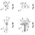
- Figure 5 is a side view of wick 115 fabricated from PVA.
- the wick 115 is about 50.8cm (20 inches) long.
- Figure 5A is an end view of wick 115 in which wick 115 possesses a rectangular cross section with a width of about 3.05mm (0.12 inches) and a height of about 2.03mm (0.08 inches).
- Figure 5B is an isometric view of wick 115.
- PVA is one of the preferred materials for fabricating wick 115. When dry it is rigid hydrophilic foam. In the presence of water or humidity it becomes soft and flexible with good chemical resistance and good water absorption properties.
- Lapevac 100 is used during laparoscopic surgery to keep the field of view while performing surgical procedures.
- the inflation creates space within the cavity thereby making it easier to perform surgery.
- a separate insufflator inflates the abdominal cavity (or other cavity) by pumping air or other gas (es) into the abdominal cavity.
- lapevac 10 removes smoke and other vaporous waste into inlet tube 112 through filter 140 and out outlet tube 120 as filtered gas.
- the second or downstream end of outlet tube 120 is attached to a hollow channel inserted into the abdominal cavity and to the insufflator by means of connector 124. Using this system, a recirculating stream of filtered gas or air enters the abdominal cavity as the smoke and waste filled vapors are removed to keep the abdominal cavity under a relatively constant inflation pressure.
- lapevac system 100 is effective in maintaining cavity inflation pressure, one problem that occurs during its operation is the clogging of inlet tube 112 and filter 140 by solid waste, water and humidity carried out of the abdominal cavity by the incoming waste stream. Because the cavity is moist and may be heated above normal temperature by some surgical procedures such as cauterization, surgical wastes can be driven off the cavity wall and internal organs in the form of particles, vapor, and liquids from broken cells and tissues. In addition, vapors within the cavity itself can be drawn into the waste stream.
- wick 115 attracts and retains the solid moist waste and the aqueous liquid waste that is drawn into inlet tube 112. Because it is sized to allow for a large airway 119 between the inner wall of inlet tube 112 and wick 115 , relative to the size of wick 115 , wick assembly 114 allows waste stream vapors and gases to move without substantial additional restriction to filter 140.
- a preferred length of wick 115 is about 50.8cm (20 inches) as this provides sufficient length for exposing the waste stream to the hydrophilic attraction of wick 115.
- the preferred rectangular shape provides more surface area to attract and hold waste particles and vapors than supplied by a round cylindrical shape.
- wick assembly 114 is also effective with passive laparoscopic filtration systems.
- a passive laparoscopic filtration system lacks the fan to actively pull waste vapors from the abdominal cavity, but instead relies on pressure supplied by the insufflator to push surgical waste through an inlet and wick assembly and filters.
- Another problem that may occur during laparoscopic surgery is the insufficient removal of waste vapor from the cavity and stratification of water vapor in the cavity which can lead to visualization problems for those observing the procedures within the abdominal cavity.
- This waste vapor can be purged by means of a two-way relief valve 150 placed in the filtered gas outlet path within outlet tube 120.
- Relief valve 150 provides the user with the ability to accelerate clearing and/or removal of stratified laparoscopic filtration waste vapor by opening a divert path while blocking the recirculating filtered gas through the normal outlet path back to the cavity. This diversion provides a sudden pressure change by supplying a rapid evacuation capability.
- Figures 6A-D show t-tap two way valve 150 (“valve 150") configured in the divert mode.
- Figure 6A is an isometric view of valve 150 showing valve inlet 151, divert 152, outlet 153, and barrel housing 155.
- Figure 6B is a top view of valve 150.
- Figure 6C is a side view of valve 150 taken from the side facing outlet 153. It can be seen that in the divert mode, outlet 153 is closed.
- FIG. 6D is a cross section of valve 150 taken along line H-H in Figure 6B .
- the arrow shows fluid flow along valve inlet 151 and through divert 152.
- Valve barrel 154 (“barrel 154") sits within divert 152 and extends past inlet 151 and outlet 153 into barrel housing 155.
- barrel passages 154a are positioned below and blocked from the fluid pathway shown by the arrows.
- the filtered gas from lapevac 100 is diverted through barrel channel 154b and out divert 152 thereby relieving the back pressure situation.
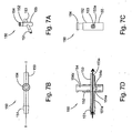
- Figures 7A-D depict t-tap two-way valve 150 configured in the flow through mode allowing filtered gas to return to the abdominal cavity.
- Figure 7A is an isometric view of valve 150 showing barrel 154 extending from the top of divert 152.
- Figure 7B shows a top view of valve 150 in the open position.
- Figure 7C is a side view facing the side of outlet 153 in which is seen the pass through channel open to outlet 153.
- Figure 7D is a cross section of valve 150 taken along line I-I in Figure 7B showing the channel configuration when valve 150 is in the open mode.
- Barrel 154 is shown extended above the top edge of divert 152. This places barrel passages 154a into channel 151a (simultaneous alignment with inlet 151 outlet 153) and blocks entrance into divert 152. Filtered gas then exits through outlet 153 into outlet tube 120 (not shown in Figure 7D ) and into the abdominal cavity.
- FIG 8A is a top view of a second embodiment of the two-way divert valve, namely stopcock valve 170 ("valve 170 "), in the closed or blocking mode. By blocking is meant that no fluid can enter valve 170.
- Figure 7B is a side view of valve 170.
- Rotor 172 is seen at the junction of inlet 171, divert 174, and outlet 173.
- rotor 172 comprises three fluid flow passages 175 within a housing (not shown) with two passages 175 on opposite sides of rotor 172 and the third passage 175 at right angles between the other two passages. In the closed (no flow) position, the blocked side, lacking a passage 175, faces inlet 171.
- valves 150 or 170 By positioning a two-way valve, such as valves 150 or 170, in outlet tube 120, the effects of back pressure from either the insufflator or unfiltered back flow from the abdominal cavity are reduced or eliminated. Filtered air can be diverted from the recirculating waste/filtered gas system until the visualization within the cavity is brought to acceptable conditions.
Landscapes
- Health & Medical Sciences (AREA)
- Chemical Kinetics & Catalysis (AREA)
- Chemical & Material Sciences (AREA)
- Surgery (AREA)
- Life Sciences & Earth Sciences (AREA)
- Engineering & Computer Science (AREA)
- Public Health (AREA)
- Heart & Thoracic Surgery (AREA)
- Medical Informatics (AREA)
- Molecular Biology (AREA)
- Animal Behavior & Ethology (AREA)
- General Health & Medical Sciences (AREA)
- Biomedical Technology (AREA)
- Veterinary Medicine (AREA)
- Otolaryngology (AREA)
- Nuclear Medicine, Radiotherapy & Molecular Imaging (AREA)
- Surgical Instruments (AREA)
- Endoscopes (AREA)
- Dental Tools And Instruments Or Auxiliary Dental Instruments (AREA)
- Respiratory Apparatuses And Protective Means (AREA)
Description
- This application claims the priority benefit of
U.S. Provisional Patent Application No. 60/904,270, filed March 1, 2007 - The invention relates to surgical procedures and, more specifically, to a device for more efficiently removing surgical waste and vapor smoke-free environment within the surgical field during laparoscopy.
- Laparoscopy is a fast growing surgical modality widely used in the treatment of certain prevalent physical ailments. Laparoscopy entails the introduction of an endoscope, light source, and surgical instruments through ports formed in the patient's abdomen. In order to facilitate the procedure, the patient's abdominal cavity is inflated with a suitable gas typically CO2 to give the surgeon additional working area and minimize obstruction. Generally, laparoscopy avoids the risks of laparotomy, which requires the surgeon to open the abdomen and carry out the required procedure by his or her direct viewing.
- However, when the laparoscopic procedure requires tissue removal by ablation, several channels through the abdominal wall are required. These include a channel for the laparoscopic camera needed for viewing the surgical field, a channel for the laser or electrosurgical instrument used to bum the target tissue, a channel for insufflation (introduction of CO2 gas into the patient's cavity to expand the patient's cavity) with CO2 gas, and a means for withdrawal of gas and smoke. Note that insufflation with a suitable gas is required during the laparoscopic procedure so as to provide both increased cavity volume and optimal visual conditions during the surgical procedure. A smoke clearing system is usually employed in order to maintain both the visual clarity and proper abdominal pressure within the expanded cavity during the procedure.
- A common procedure for positioning the laparoscopic assembly in the patient's abdominal cavity includes first making an incision into the patient's abdominal wall through which a large gauge needle is inserted. A suitable gas, typically CO2, is then introduced into the patient's abdominal cavity through the needle. The needle is then replaced with a trocar, which is then removed leaving behind a sleeve, or cannula, through which a laparoscope is introduced into the abdominal cavity. In order to perform laser or electrosurgery one or two additional small incisions are made in the abdominal wall over the surgical site and cannula/trocar assemblies positioned accordingly. These cannula/trocar assemblies may be used for the positioning of the insufflation tube as well as any other surgical instruments that may be required for the particular laparoscopic procedure.
- A laparoscopic procedure typically requires a surgeon to employ either electrosurgery or laser surgery within the confined space of the patient's abdominal cavity. This surgery typically involves tissue burning or ablation. This tissue burning leads to the creation of smoke. Surgical smoke within the confines of a patient's abdominal cavity reduces the surgeon's view of the surgical site, increases the patient's hematocrit levels, and causes delays in the surgery while the smoke is cleared from the laparoscopic field. Efficient removal of the smoke is thus a necessity for the surgical team during the laparoscopic procedure.
- Although a laparoscopic evacuation system ("lapevac system") is effective in maintaining cavity inflation pressure, one problem that occurs during its operation is the clogging of the inlet tube and filter by solid waste, water and humidity carried out of the abdominal cavity by the incoming waste stream. Because the cavity is moist and may be heated above normal temperature by some surgical procedures such as cauterization, surgical wastes can be driven off the cavity wall and internal organs in the form of particles, vapor, and liquids from broken cells and tissues. In addition, vapors within the cavity itself can be drawn into the waste stream. Another problem that may occur during laparoscopic surgery is the insufficient removal of waste vapor from the cavity, stratification of water vapor in the cavity as well as other visualization problems.
- Therefore, there is a need in the field for an improved laparoscopic surgical system that is designed to prevent clogging of the inlet and filter by surgical waste and that will reduce or eliminate stratification of smoke and water vapor in the abdominal cavity during laparoscopic surgery
-
US 6544210 discloses the preamble ofindependent claim 1 andUS 2005 000196 discloses a smoke removal system with a filter in the inlet means. - According to one aspect of the present invention, there is provided an inlet means as claimed in
claim 1.
A smoke removal apparatus may comprise the inlet means. The smoke removal apparatus may comprise a multi-outlet valve incorporated into an outlet means. - One object of the present invention is to reduce or eliminate blocking of the inlet means by surgical waste.
- A second object of the present invention is reduce or eliminate stratification of surgical smoke and water vapor in the abdominal cavity by supplying a venting valve on the outlet means of the surgical smoke removal device to effect quick removal of smoke and water vapor.
- The nature and mode of operation of the present invention will now be more fully described in the following detailed description of the invention taken with the accompanying drawing figures, in which:
-
Figure 1 is a schematic view of a laparoscopic smoke evacuation system of the prior art depicting the arrangement of the smoke evacuation system during laparoscopic surgery; -
Figure 2 is a top perspective view of a typical disposable laparoscopic smoke evacuation system according to an embodiment of the present invention; -
Figure 3 is an exploded top perspective view of the disposable laparoscopic smoke evacuation system shown inFigure 2 ; -
Figure 3A depicts an enlarged view of the wick assembly inserted into the inlet tube of the smoke evacuation system; -
Figure 4 is a top perspective view depicting the components of the wick assembly in an assembled condition; -
Figure 4A is a top perspective view of a partially disassembled wick assembly; -
Figure 4B is a side view of the assembled wick assembly ; -
Figure 5 is a side view of the wick component of the wick assembly ; -
Figure 5A is an end view showing the wick depicted inFigure 4 ; -
Figure 5B is an isometric view of the wick shown inFigure 4 ; -
Figure 6A is an isometric view of one embodiment of the two-way valve in the divert mode; -
Figure 6B is a top view of the two way outlet valve in the divert mode; -
Figure 6C is a side view of the two-way outlet valve from the side facing the outlet port in the divert mode; -
Figure 6D is a cross section of the two-way valve taken along line H-H inFigure 5B in the divert mode; -
Figure 7A is an isometric view of the two-way valve showing the valve barrel in the open (flow through) mode; -
Figure 7B shows a top view of the two-way valve in the open mode; -
Figure 7C is a side view of the two-way valve in the open mode facing the side of the outlet showing the open channel to the valve outlet; -
Figure 7D is a cross section of the two-way valve taken along line I-I inFigure 6B showing the channel configuration when the valve is in the open mode; -
Figure 8A is a top view of a second embodiment of the two-way outlet divert valve in the off mode; -
Figure 8B is a top view of the second embodiment of the two-way outlet valve in the open mode; and, -
Figure 8C is a top view of the second embodiment of the two-way outlet valve in the divert mode. - At the outset, it should be appreciated that like drawing numbers on different drawing views identify identical structural elements of the invention. While the present invention is described with respect to what is presently considered to be the preferred embodiments, it is understood that the invention is not limited to the disclosed embodiment.
- Furthermore, it is understood that this invention is not limited to the particular methodology, materials and modifications described and as such may, of course, vary. It is also understood that the terminology used herein is for the purpose of describing particular embodiments only, and is not intended to limit the scope of the present invention.
- Adverting now to the figures,
Figure 1 is a schematic view of a laparoscopic smoke evacuation system of the prior art depicting the arrangement of the smoke evacuation system during laparoscopic surgery.Smoke clearing device 10 includeshousing 12.Housing 12 may be made out of a variety of materials, such as a metal or a plastic, as long as the material facilitates the device's use and is preferably disposable. Thehousing 12 preferably has a generally rectangular box shape or it may have a generally cylindrical hollow shape, preferably with rounded corners. Thehousing 12 contains aninlet port 14 at one end, i.e., on one side and an outlet port 16 at the other end, i.e., on the opposite side. One end of aninlet tube 18 is connected to theinlet port 14. One end of anoutlet tube 20 is connected to the outlet port 16. This tubing is preferably conventional sterile flexible plastic tubing. It is envisioned that conventionalLuer lock structures 22 will be used to connect thetubes housing 12, but other locking structures could alternatively be used. - The patient's inner cavity, such as the abdominal cavity, is shown as 24 and the patient's skin is schematically shown as 25 in
Figure 1 . The patient's tissue which is to be removed is shown as 26, with the surgical smoke shown and indicated as 26a, 26b, and 26c. Three trocars containing laparoscopicsurgical instrument clusters skin 25 into thecavity 24. - These groups of instruments are representative of the type of instruments that are typically used in laparoscopic surgery. Each instrument cluster includes a cannula/trocar for introducing the instrument into the patient's cavity and maintaining a seal to the
cavity 24 to preclude gas escape from thecavity 24. Each cannula/trocar has a single channel or passage along its length that allows instruments to be inserted into the body while maintaining the intra-abdominal pressure created by insufflation.Instrument cluster 28 is a single channel instrument cluster which serves to house thelaser instrument 34 and direct the laser beam to the operating site. Anannular channel 36 around theinstrument 34 within the trocar serves as an annular egress passage from near the operating site for gas to be drawn around thelaser instrument 34 and out of the patient's cavity to thesmoke clearing device 10 of the present invention. -
Figure 2 is a top perspective view of a typical disposable laparoscopic smoke evacuation system 100 ("lapevac 100"). Such devices are described inU.S. Patent No. 6,544,210 to Trudel, et al.
Housing 111 is shown with inlet means, in thiscase inlet tube 112 and outlet means, in thiscase outlet tube 120 attached toinlet attachment 112a andoutlet attachment 120a, respectively. Inserted into the input end ofinlet tube 112 iswick assembly 114. Attached to theoutlet attachment 120a is the inlet of one embodiment of a multi-outlet relief valve, in this case a two-way bleed or relief valve, t-tap valve 150. By two-way valve is meant a valve that has at least two outlets that allow material, such as a gas or liquid fluid, that enters the valve to be directed to one of two or more different outlet flow paths. Also seen is y-connector 124 ("connector 124") at the end ofoutlet tube 120. Persons of skill in the art will recognize that the two-way valves may be connected tooutlet tube 120 in any convenient position within the length ofoutlet tube 120 and that valves having more than two outlets may also be used. -
Figure 3 is an exploded top perspective view oflapevac 100.Inlet hose 112 is seen attached toinlet attachment 112a.Inlet assembly 130 includesinlet 131 which covers the fan or pump assembly to includeimpeller cover 132,impeller 133,fan 134, andfan mount 134a which are all attached tomotor 136.Battery cover 111a covers battery (ies) 138 used topower motor 136. Although a plurality of AA batteries are shown inFigure 3 , persons of skill in the art will recognize that a single battery, various appropriate battery assemblies with different capacities, or alternative ac power sources may be used to provide power tomotor 136. -
Outlet 142 coversfilter 140 positioned on the downstream side offan assembly 130. Preferably thefilter 140 includes activatedcarbon media 141a as a prefilter plus ultra low particulate air (ULPA)filter 141b.Outlet attachment 120a extends fromoutlet 142 and is seen connected to t-tap valve 150. One end ofoutlet tube 120 is connected to t-tap valve 150, while the other end is connected toconnector 124. A locking means 126 is positioned on at least one outlet of y-connector 124 to enable y-connector 124 to be securely attached to an additional component. The locking means 126 is a luer lock.Cap 127 is used to block an unused outlet of y-connector 124. The locking means 116, such as a luer lock, may be positioned at the input end ofinlet tube 112 as shown inFigures 2 and3 . Locking means utilized throughout the invention are defined as connections between two components that prevent the escape of vapor, liquid, or fumes from the connection itself. Examples of locking means are luer locks, tube connections in which one tube is inserted into another tube, interference fittings, Colder couplers and other connectors known t those skilled in the art that prevent the escape of fumes from a connection point. - Y-
connector 124 receives filtered gas fromlapevac 100. One of the two outlets ofy-connector 124 can be connected to an insufflator while the second outlet can be connected to a second inlet into the abdominal cavity enabling gas filtered by lapevac 100 ("filtered gas") to be pumped into the abdominal cavity at two locations to help remove waste vapors generated by the laparoscopic surgical procedures. -
Figure 3A depicts an enlarged view ofwick assembly 114 incorporated intoinlet tube 112.Inlet tube 112 is cut way to more clearly showwick 115.Luer lock 116 is shown at the.inlet end ofinlet tube 112. -
Figure 4 is a top perspective view depicting the components ofwick assembly 114 joined together in an assembled condition.Luer lock 116 is shown at the inlet end ofinlet tube 112. Interference fitting 117 ("fitting 117") is attached toluer lock 116 andwick 115.Wick assembly 114 is inserted intoinlet tube 112 and held in place by the friction of interference fitting 117 against the inner wall ofinlet tube 112.Wick 115 is in the form of a strand or filament that extends intoinlet tube 112. Preferably,wick 115 is fabricated from a hydrophilic material such as polyvinyl alcohol (PVA) or cotton.Wick 115 is sized with a diameter small enough to allow sufficient space forairway 119 betweenwick 115 and inner wall ofinlet tube 112 to form a passage to allow smoke, air and other fluids to be easily drawn intoinlet tube 112 and pass throughfilter 140 oflapevac 100 tooutlet tube 120 in the form of filtered gas. By hydrophilic is meant the property of attracting and to at least some extent absorbing liquids and fluids. -
Figure 4A is a top perspective view of partially disassembledwick assembly 114. Fitting 117 is attached toluer lock 116 and inserted intoinlet tube 112.Luer lock 116 or other locking means used should be hollow in order to allow the flow of fluid, including vapors and gases, into and throughinlet tube 112. Similarly, fitting 117 should also be hollow to allow for sufficient air flow to move incoming vapor and gas without taxinglapevac 100.Wick 115 is attached to fitting 117 and the luer lock-fitting-wick assembly is inserted intoinlet tube 112.Figure 4B is a side view ofwick assembly 114 showing more clearly fitting 117 andwick 115 withininlet tube 112 andairway 119. -
Figure 5 is a side view ofwick 115 fabricated from PVA. Thewick 115 is about 50.8cm (20 inches) long.Figure 5A is an end view ofwick 115 in which wick 115 possesses a rectangular cross section with a width of about 3.05mm (0.12 inches) and a height of about 2.03mm (0.08 inches).Figure 5B is an isometric view ofwick 115. PVA is one of the preferred materials for fabricatingwick 115. When dry it is rigid hydrophilic foam. In the presence of water or humidity it becomes soft and flexible with good chemical resistance and good water absorption properties. -
Lapevac 100 is used during laparoscopic surgery to keep the field of view while performing surgical procedures. The inflation creates space within the cavity thereby making it easier to perform surgery. A separate insufflator inflates the abdominal cavity (or other cavity) by pumping air or other gas (es) into the abdominal cavity. To remove surgically generated smoke and other vapors,lapevac 10 removes smoke and other vaporous waste intoinlet tube 112 throughfilter 140 and outoutlet tube 120 as filtered gas. The second or downstream end ofoutlet tube 120 is attached to a hollow channel inserted into the abdominal cavity and to the insufflator by means ofconnector 124. Using this system, a recirculating stream of filtered gas or air enters the abdominal cavity as the smoke and waste filled vapors are removed to keep the abdominal cavity under a relatively constant inflation pressure. - Although
lapevac system 100 is effective in maintaining cavity inflation pressure, one problem that occurs during its operation is the clogging ofinlet tube 112 and filter 140 by solid waste, water and humidity carried out of the abdominal cavity by the incoming waste stream. Because the cavity is moist and may be heated above normal temperature by some surgical procedures such as cauterization, surgical wastes can be driven off the cavity wall and internal organs in the form of particles, vapor, and liquids from broken cells and tissues. In addition, vapors within the cavity itself can be drawn into the waste stream. - Because it is hydrophilic,
wick 115, attracts and retains the solid moist waste and the aqueous liquid waste that is drawn intoinlet tube 112. Because it is sized to allow for alarge airway 119 between the inner wall ofinlet tube 112 andwick 115, relative to the size ofwick 115,wick assembly 114 allows waste stream vapors and gases to move without substantial additional restriction to filter 140. A preferred length ofwick 115 is about 50.8cm (20 inches) as this provides sufficient length for exposing the waste stream to the hydrophilic attraction ofwick 115. In addition, the preferred rectangular shape provides more surface area to attract and hold waste particles and vapors than supplied by a round cylindrical shape. - It will be recognized that
wick assembly 114 is also effective with passive laparoscopic filtration systems. A passive laparoscopic filtration system lacks the fan to actively pull waste vapors from the abdominal cavity, but instead relies on pressure supplied by the insufflator to push surgical waste through an inlet and wick assembly and filters. - Another problem that may occur during laparoscopic surgery is the insufficient removal of waste vapor from the cavity and stratification of water vapor in the cavity which can lead to visualization problems for those observing the procedures within the abdominal cavity. This waste vapor can be purged by means of a two-
way relief valve 150 placed in the filtered gas outlet path withinoutlet tube 120.Relief valve 150 provides the user with the ability to accelerate clearing and/or removal of stratified laparoscopic filtration waste vapor by opening a divert path while blocking the recirculating filtered gas through the normal outlet path back to the cavity. This diversion provides a sudden pressure change by supplying a rapid evacuation capability. -
Figures 6A-D show t-tap two way valve 150 ("valve 150") configured in the divert mode.Figure 6A is an isometric view ofvalve 150 showingvalve inlet 151, divert 152,outlet 153, andbarrel housing 155.Figure 6B is a top view ofvalve 150.Figure 6C is a side view ofvalve 150 taken from theside facing outlet 153. It can be seen that in the divert mode,outlet 153 is closed. -
Figure 6D is a cross section ofvalve 150 taken along line H-H inFigure 6B . The arrow shows fluid flow alongvalve inlet 151 and through divert 152. Valve barrel 154 ("barrel 154") sits within divert 152 and extendspast inlet 151 andoutlet 153 intobarrel housing 155. In the divert mode shown,barrel passages 154a are positioned below and blocked from the fluid pathway shown by the arrows. Thus, the filtered gas fromlapevac 100 is diverted throughbarrel channel 154b and out divert 152 thereby relieving the back pressure situation. -
Figures 7A-D depict t-tap two-way valve 150 configured in the flow through mode allowing filtered gas to return to the abdominal cavity.Figure 7A is an isometric view ofvalve 150showing barrel 154 extending from the top of divert 152.Figure 7B shows a top view ofvalve 150 in the open position.Figure 7C is a side view facing the side ofoutlet 153 in which is seen the pass through channel open tooutlet 153. -
Figure 7D is a cross section ofvalve 150 taken along line I-I inFigure 7B showing the channel configuration whenvalve 150 is in the open mode.Barrel 154 is shown extended above the top edge of divert 152. This placesbarrel passages 154a intochannel 151a (simultaneous alignment withinlet 151 outlet 153) and blocks entrance into divert 152. Filtered gas then exits throughoutlet 153 into outlet tube 120 (not shown inFigure 7D ) and into the abdominal cavity. -
Figure 8A is a top view of a second embodiment of the two-way divert valve, namely stopcock valve 170 ("valve 170"), in the closed or blocking mode. By blocking is meant that no fluid can entervalve 170.Figure 7B is a side view ofvalve 170.Rotor 172 is seen at the junction ofinlet 171, divert 174, andoutlet 173. Persons of skill in the art will recognize thatrotor 172 comprises threefluid flow passages 175 within a housing (not shown) with twopassages 175 on opposite sides ofrotor 172 and thethird passage 175 at right angles between the other two passages. In the closed (no flow) position, the blocked side, lacking apassage 175, facesinlet 171. This configuration closes the passage of filtered gas in any direction through valve 70. In the divert position,Figure 8C , the blocked side is rotated to faceoutlet 173. In this configuration, filtered gas flows through divert 172. In the flow through mode,Figure 8B , the blocked side is rotated to face divert 172, forcing the filtered gas to flow through outlet 73. - It is apparent that by positioning a two-way valve, such as
valves outlet tube 120, the effects of back pressure from either the insufflator or unfiltered back flow from the abdominal cavity are reduced or eliminated. Filtered air can be diverted from the recirculating waste/filtered gas system until the visualization within the cavity is brought to acceptable conditions. - Thus, it is seen that the objects of the present invention are efficiently obtained, although modifications and changes to the invention should be readily apparent to those having ordinary skill in the art, which modifications are intended to be within the scope of the invention as defined by the claims.
Claims (14)
- An inlet means for a smoke removal apparatus comprising:an inlet tube (112) having a first end and a second end and a hollow locking means (116) at said second end to attach to an inlet of said smoke removal apparatus; and, a hydrophilic assembly (114), said hydrophilic assembly (114) comprising:a hydrophilic member (115);a friction fitting (117) attached to said hydrophilic member (115), said friction fitting (117) defining an orifice; and,said hollow locking means (116) attached to said friction fitting;characterised in that the hydrophilic member is a hydrophilic wick (115);wherein said friction fitting (117) is arranged to hold the hydrophilic wick (115) in the inlet tube (112) between the friction fitting (117) and an inner wall of the inlet tube (112) such that an airway (119) is provided alongside the hydrophilic wick (115), between the hydrophilic wick (115) and the inner wall of the inlet tube (112),the orifice of the friction fitting (117) provides access to the airway (119), and an interior of the hollow locking means (116) is also in fluid communication with the airway (119).
- The inlet means as recited in Claim 1 wherein said hydrophilic wick (115) is PVA.
- The inlet means (114) as recited in Claim 1 wherein said hydrophilic wick (115) is cotton.
- A smoke removal apparatus having a housing (111); inlet means (112) according to claim 1 for defining an inlet pathway for impure gas from a surgical cavity to said housing, said locking means being for connecting said surgical cavity to said inlet pathway; filter means (140) for filtering impurities from impure gas to form filtered gas; outlet means (120) for defining an outlet pathway for said filtered gas from said housing to said surgical cavity, and a fan (134) for drawing impure gas from said surgical cavity through said inlet means (112), and through said filter means (140) to form said filtered gas and for driving said filtered gas through said outlet means (120) into said surgical cavity, wherein said outlet means (120) are adapted to a laparoscopic surgical instrument assembly,
and said hydrophilic wick (115) is inserted into and attached to said locking means of said inlet means. - The smoke removal apparatus as recited in Claim 4 wherein said hydrophilic wick (115) is fabricated from polyvinyl alcohol (PVA).
- The smoke removal apparatus as recited in Claim 4 wherein said hydrophilic wick (115) is fabricated from cotton.
- The smoke removal apparatus as recited in Claim 4 wherein said hydrophilic wick (115) has a rectangular cross section.
- The smoke removal apparatus as recited in Claim 4 further comprising a multi-outlet valve (124) incorporated into said outlet means (120).
- The smoke removal apparatus as recited in Claim 8 wherein said multi-outlet (124) is a two-way outlet valve.
- The smoke removal apparatus as recited in Claim 9 wherein said two-way relief valve is a t-tap valve.
- The smoke removal apparatus as recited in Claim 9 wherein said two-way relief valve is a stop cock having two outlets.
- The smoke removal apparatus as recited in Claim 4 wherein said filter means (140) includes a pre-filter (141a).
- An inlet means according to any of claims 1 to 3, in which the hydrophilic wick (115) is in the form of a filament.
- A smoke removal apparatus according to any of claims 4 to 12, in which the hydrophilic wick (115) is in the form of a filament.
Applications Claiming Priority (2)
| Application Number | Priority Date | Filing Date | Title |
|---|---|---|---|
| US90427007P | 2007-03-01 | 2007-03-01 | |
| PCT/US2008/002759 WO2008109014A2 (en) | 2007-03-01 | 2008-02-29 | Wick and relief valve for disposable laparscopic smoke evacuation system |
Publications (3)
| Publication Number | Publication Date |
|---|---|
| EP2117621A2 EP2117621A2 (en) | 2009-11-18 |
| EP2117621A4 EP2117621A4 (en) | 2012-04-18 |
| EP2117621B1 true EP2117621B1 (en) | 2013-11-06 |
Family
ID=39738971
Family Applications (1)
| Application Number | Title | Priority Date | Filing Date |
|---|---|---|---|
| EP20080726317 Active EP2117621B1 (en) | 2007-03-01 | 2008-02-29 | Wick and relief valve for disposable laparscopic smoke evacuation system |
Country Status (7)
| Country | Link |
|---|---|
| US (1) | US9011366B2 (en) |
| EP (1) | EP2117621B1 (en) |
| AU (1) | AU2008223473B2 (en) |
| CA (1) | CA2679832C (en) |
| DK (1) | DK2117621T3 (en) |
| ES (1) | ES2441261T3 (en) |
| WO (1) | WO2008109014A2 (en) |
Cited By (1)
| Publication number | Priority date | Publication date | Assignee | Title |
|---|---|---|---|---|
| CN109171948A (en) * | 2018-10-26 | 2019-01-11 | 丽水市中心医院 | The system of cryoablation needle and application the cryoablation needle |
Families Citing this family (150)
| Publication number | Priority date | Publication date | Assignee | Title |
|---|---|---|---|---|
| US8585646B2 (en) * | 2008-03-03 | 2013-11-19 | Lexion Medical, Llc | System and method to vent gas from a body cavity |
| US8882768B2 (en) | 2009-04-24 | 2014-11-11 | Megadyne Medical Products, Inc. | Hand piece with adjustable utility conduit |
| US8882767B2 (en) | 2009-04-24 | 2014-11-11 | Megadyne Medical Products, Inc. | Electrosurgical instrument with adjustable utility conduit |
| US9656816B2 (en) * | 2011-08-12 | 2017-05-23 | Cyclone Catalyst Properties Llc | Systems and methods for converter bed unloading and loading |
| US8608816B2 (en) | 2012-01-10 | 2013-12-17 | Buffalo Filter Llc | Fluid filtration device and system |
| US9415160B2 (en) * | 2012-05-21 | 2016-08-16 | Buffalo Filter Llc | Fluid filtration device and system |
| US11871901B2 (en) | 2012-05-20 | 2024-01-16 | Cilag Gmbh International | Method for situational awareness for surgical network or surgical network connected device capable of adjusting function based on a sensed situation or usage |
| WO2014111083A1 (en) * | 2013-01-15 | 2014-07-24 | W.O.M. World Of Medicine Gmbh | Insufflation tube comprising a humidifying material and a heating element, for laparoscopy |
| US9375253B2 (en) | 2013-03-14 | 2016-06-28 | Megadyne Medical Products, Inc. | Electrosurgical instrument |
| US9259260B2 (en) | 2013-03-14 | 2016-02-16 | Megadyne Medical Products, Inc. | Fluid evacuation device |
| USD709196S1 (en) | 2013-03-15 | 2014-07-15 | Megadyne Medical Products, Inc. | Hand piece |
| US10198966B2 (en) * | 2013-07-24 | 2019-02-05 | Applied Medical Resources Corporation | Advanced first entry model for surgical simulation |
| US9161680B2 (en) | 2013-11-26 | 2015-10-20 | Bracco Diagnostics Inc. | Disposable air/water valve for an endoscopic device |
| US10422727B2 (en) | 2014-08-10 | 2019-09-24 | Harry Leon Pliskin | Contaminant monitoring and air filtration system |
| GB201414533D0 (en) * | 2014-08-15 | 2014-10-01 | Asalus Medical Instr Ltd | Laparoscopic access port |
| US9962520B2 (en) * | 2014-10-15 | 2018-05-08 | Surgiquest, Inc. | Branching multi-lumen tube set for laparoscopic surgical procedures involving smoke evacuation |
| US11504192B2 (en) | 2014-10-30 | 2022-11-22 | Cilag Gmbh International | Method of hub communication with surgical instrument systems |
| CA2990670C (en) | 2015-07-02 | 2022-08-16 | Northgate Technologies Inc. | Gas recirculation system |
| TWI552715B (en) * | 2015-10-12 | 2016-10-11 | 台灣先進手術醫療器材股份有限公司 | Valve mechanism for suction and irrigation instrument |
| US11564756B2 (en) | 2017-10-30 | 2023-01-31 | Cilag Gmbh International | Method of hub communication with surgical instrument systems |
| US11317919B2 (en) | 2017-10-30 | 2022-05-03 | Cilag Gmbh International | Clip applier comprising a clip crimping system |
| US11229436B2 (en) | 2017-10-30 | 2022-01-25 | Cilag Gmbh International | Surgical system comprising a surgical tool and a surgical hub |
| US11311342B2 (en) | 2017-10-30 | 2022-04-26 | Cilag Gmbh International | Method for communicating with surgical instrument systems |
| US10980560B2 (en) | 2017-10-30 | 2021-04-20 | Ethicon Llc | Surgical instrument systems comprising feedback mechanisms |
| US11911045B2 (en) | 2017-10-30 | 2024-02-27 | Cllag GmbH International | Method for operating a powered articulating multi-clip applier |
| US11801098B2 (en) | 2017-10-30 | 2023-10-31 | Cilag Gmbh International | Method of hub communication with surgical instrument systems |
| US11510741B2 (en) | 2017-10-30 | 2022-11-29 | Cilag Gmbh International | Method for producing a surgical instrument comprising a smart electrical system |
| US11026687B2 (en) | 2017-10-30 | 2021-06-08 | Cilag Gmbh International | Clip applier comprising clip advancing systems |
| US11291510B2 (en) | 2017-10-30 | 2022-04-05 | Cilag Gmbh International | Method of hub communication with surgical instrument systems |
| US10758293B2 (en) | 2017-11-29 | 2020-09-01 | Megadyne Medical Products, Inc. | Smoke evacuation device inlet and outlet manifolds |
| US11725664B2 (en) | 2017-11-29 | 2023-08-15 | Megadyne Medical Products, Inc. | Noise and vibration management for smoke evacuation system |
| USD886976S1 (en) | 2017-11-29 | 2020-06-09 | Megadyne Medical Products, Inc. | Filter cartridge |
| USD912762S1 (en) | 2017-11-29 | 2021-03-09 | Megadyne Medical Products, Inc. | Fluid trap |
| US11389225B2 (en) | 2017-11-29 | 2022-07-19 | Megadyne Medical Products, Inc. | Smoke evacuation device remote activation system |
| US11234754B2 (en) | 2017-11-29 | 2022-02-01 | Megadyne Medical Products, Inc. | Smoke evacuation device |
| US10631916B2 (en) | 2017-11-29 | 2020-04-28 | Megadyne Medical Products, Inc. | Filter connection for a smoke evacuation device |
| US10758855B2 (en) | 2017-11-29 | 2020-09-01 | Megadyne Medical Products, Inc. | Smoke evacuation system fluid trap |
| USD868236S1 (en) | 2017-11-29 | 2019-11-26 | Megadyne Medical Products, Inc. | Smoke evacuation device control panel |
| US10758856B2 (en) | 2017-11-29 | 2020-09-01 | Megadyne Medical Products, Inc. | Filter medium compression system for smoke evacuation |
| USD868287S1 (en) | 2017-11-29 | 2019-11-26 | Megadyne Medical Products, Inc. | Remote activation clip |
| US11160605B2 (en) | 2017-12-28 | 2021-11-02 | Cilag Gmbh International | Surgical evacuation sensing and motor control |
| US10758310B2 (en) | 2017-12-28 | 2020-09-01 | Ethicon Llc | Wireless pairing of a surgical device with another device within a sterile surgical field based on the usage and situational awareness of devices |
| US11903601B2 (en) | 2017-12-28 | 2024-02-20 | Cilag Gmbh International | Surgical instrument comprising a plurality of drive systems |
| US11571234B2 (en) | 2017-12-28 | 2023-02-07 | Cilag Gmbh International | Temperature control of ultrasonic end effector and control system therefor |
| US11234756B2 (en) | 2017-12-28 | 2022-02-01 | Cilag Gmbh International | Powered surgical tool with predefined adjustable control algorithm for controlling end effector parameter |
| US11069012B2 (en) | 2017-12-28 | 2021-07-20 | Cilag Gmbh International | Interactive surgical systems with condition handling of devices and data capabilities |
| US11364075B2 (en) | 2017-12-28 | 2022-06-21 | Cilag Gmbh International | Radio frequency energy device for delivering combined electrical signals |
| US11273001B2 (en) | 2017-12-28 | 2022-03-15 | Cilag Gmbh International | Surgical hub and modular device response adjustment based on situational awareness |
| US11969216B2 (en) | 2017-12-28 | 2024-04-30 | Cilag Gmbh International | Surgical network recommendations from real time analysis of procedure variables against a baseline highlighting differences from the optimal solution |
| US10943454B2 (en) | 2017-12-28 | 2021-03-09 | Ethicon Llc | Detection and escalation of security responses of surgical instruments to increasing severity threats |
| US11056244B2 (en) | 2017-12-28 | 2021-07-06 | Cilag Gmbh International | Automated data scaling, alignment, and organizing based on predefined parameters within surgical networks |
| US11844579B2 (en) | 2017-12-28 | 2023-12-19 | Cilag Gmbh International | Adjustments based on airborne particle properties |
| US11672605B2 (en) | 2017-12-28 | 2023-06-13 | Cilag Gmbh International | Sterile field interactive control displays |
| US11076921B2 (en) | 2017-12-28 | 2021-08-03 | Cilag Gmbh International | Adaptive control program updates for surgical hubs |
| US11109866B2 (en) | 2017-12-28 | 2021-09-07 | Cilag Gmbh International | Method for circular stapler control algorithm adjustment based on situational awareness |
| US11266468B2 (en) | 2017-12-28 | 2022-03-08 | Cilag Gmbh International | Cooperative utilization of data derived from secondary sources by intelligent surgical hubs |
| US11786251B2 (en) | 2017-12-28 | 2023-10-17 | Cilag Gmbh International | Method for adaptive control schemes for surgical network control and interaction |
| US11832899B2 (en) | 2017-12-28 | 2023-12-05 | Cilag Gmbh International | Surgical systems with autonomously adjustable control programs |
| US11419630B2 (en) | 2017-12-28 | 2022-08-23 | Cilag Gmbh International | Surgical system distributed processing |
| US10987178B2 (en) | 2017-12-28 | 2021-04-27 | Ethicon Llc | Surgical hub control arrangements |
| US11969142B2 (en) | 2017-12-28 | 2024-04-30 | Cilag Gmbh International | Method of compressing tissue within a stapling device and simultaneously displaying the location of the tissue within the jaws |
| US11376002B2 (en) | 2017-12-28 | 2022-07-05 | Cilag Gmbh International | Surgical instrument cartridge sensor assemblies |
| US11132462B2 (en) | 2017-12-28 | 2021-09-28 | Cilag Gmbh International | Data stripping method to interrogate patient records and create anonymized record |
| US11045591B2 (en) | 2017-12-28 | 2021-06-29 | Cilag Gmbh International | Dual in-series large and small droplet filters |
| US11896443B2 (en) | 2017-12-28 | 2024-02-13 | Cilag Gmbh International | Control of a surgical system through a surgical barrier |
| US11311306B2 (en) | 2017-12-28 | 2022-04-26 | Cilag Gmbh International | Surgical systems for detecting end effector tissue distribution irregularities |
| US20190201118A1 (en) | 2017-12-28 | 2019-07-04 | Ethicon Llc | Display arrangements for robot-assisted surgical platforms |
| US11308075B2 (en) | 2017-12-28 | 2022-04-19 | Cilag Gmbh International | Surgical network, instrument, and cloud responses based on validation of received dataset and authentication of its source and integrity |
| US11419667B2 (en) | 2017-12-28 | 2022-08-23 | Cilag Gmbh International | Ultrasonic energy device which varies pressure applied by clamp arm to provide threshold control pressure at a cut progression location |
| US11864728B2 (en) | 2017-12-28 | 2024-01-09 | Cilag Gmbh International | Characterization of tissue irregularities through the use of mono-chromatic light refractivity |
| US11464535B2 (en) | 2017-12-28 | 2022-10-11 | Cilag Gmbh International | Detection of end effector emersion in liquid |
| US10966791B2 (en) | 2017-12-28 | 2021-04-06 | Ethicon Llc | Cloud-based medical analytics for medical facility segmented individualization of instrument function |
| US11589888B2 (en) | 2017-12-28 | 2023-02-28 | Cilag Gmbh International | Method for controlling smart energy devices |
| US11324557B2 (en) | 2017-12-28 | 2022-05-10 | Cilag Gmbh International | Surgical instrument with a sensing array |
| US11202570B2 (en) | 2017-12-28 | 2021-12-21 | Cilag Gmbh International | Communication hub and storage device for storing parameters and status of a surgical device to be shared with cloud based analytics systems |
| US11013563B2 (en) | 2017-12-28 | 2021-05-25 | Ethicon Llc | Drive arrangements for robot-assisted surgical platforms |
| US11410259B2 (en) | 2017-12-28 | 2022-08-09 | Cilag Gmbh International | Adaptive control program updates for surgical devices |
| US11446052B2 (en) | 2017-12-28 | 2022-09-20 | Cilag Gmbh International | Variation of radio frequency and ultrasonic power level in cooperation with varying clamp arm pressure to achieve predefined heat flux or power applied to tissue |
| US11147607B2 (en) | 2017-12-28 | 2021-10-19 | Cilag Gmbh International | Bipolar combination device that automatically adjusts pressure based on energy modality |
| US11304763B2 (en) | 2017-12-28 | 2022-04-19 | Cilag Gmbh International | Image capturing of the areas outside the abdomen to improve placement and control of a surgical device in use |
| US11304699B2 (en) | 2017-12-28 | 2022-04-19 | Cilag Gmbh International | Method for adaptive control schemes for surgical network control and interaction |
| US11818052B2 (en) | 2017-12-28 | 2023-11-14 | Cilag Gmbh International | Surgical network determination of prioritization of communication, interaction, or processing based on system or device needs |
| US11291495B2 (en) | 2017-12-28 | 2022-04-05 | Cilag Gmbh International | Interruption of energy due to inadvertent capacitive coupling |
| US10932872B2 (en) | 2017-12-28 | 2021-03-02 | Ethicon Llc | Cloud-based medical analytics for linking of local usage trends with the resource acquisition behaviors of larger data set |
| US11096693B2 (en) | 2017-12-28 | 2021-08-24 | Cilag Gmbh International | Adjustment of staple height of at least one row of staples based on the sensed tissue thickness or force in closing |
| US11771487B2 (en) | 2017-12-28 | 2023-10-03 | Cilag Gmbh International | Mechanisms for controlling different electromechanical systems of an electrosurgical instrument |
| US11100631B2 (en) | 2017-12-28 | 2021-08-24 | Cilag Gmbh International | Use of laser light and red-green-blue coloration to determine properties of back scattered light |
| US11678881B2 (en) | 2017-12-28 | 2023-06-20 | Cilag Gmbh International | Spatial awareness of surgical hubs in operating rooms |
| US11253315B2 (en) | 2017-12-28 | 2022-02-22 | Cilag Gmbh International | Increasing radio frequency to create pad-less monopolar loop |
| US11432885B2 (en) | 2017-12-28 | 2022-09-06 | Cilag Gmbh International | Sensing arrangements for robot-assisted surgical platforms |
| US11602393B2 (en) | 2017-12-28 | 2023-03-14 | Cilag Gmbh International | Surgical evacuation sensing and generator control |
| US11423007B2 (en) | 2017-12-28 | 2022-08-23 | Cilag Gmbh International | Adjustment of device control programs based on stratified contextual data in addition to the data |
| US10892995B2 (en) | 2017-12-28 | 2021-01-12 | Ethicon Llc | Surgical network determination of prioritization of communication, interaction, or processing based on system or device needs |
| US11744604B2 (en) | 2017-12-28 | 2023-09-05 | Cilag Gmbh International | Surgical instrument with a hardware-only control circuit |
| US11540855B2 (en) | 2017-12-28 | 2023-01-03 | Cilag Gmbh International | Controlling activation of an ultrasonic surgical instrument according to the presence of tissue |
| US11659023B2 (en) | 2017-12-28 | 2023-05-23 | Cilag Gmbh International | Method of hub communication |
| US10755813B2 (en) | 2017-12-28 | 2020-08-25 | Ethicon Llc | Communication of smoke evacuation system parameters to hub or cloud in smoke evacuation module for interactive surgical platform |
| US11696760B2 (en) | 2017-12-28 | 2023-07-11 | Cilag Gmbh International | Safety systems for smart powered surgical stapling |
| US11896322B2 (en) | 2017-12-28 | 2024-02-13 | Cilag Gmbh International | Sensing the patient position and contact utilizing the mono-polar return pad electrode to provide situational awareness to the hub |
| US11832840B2 (en) | 2017-12-28 | 2023-12-05 | Cilag Gmbh International | Surgical instrument having a flexible circuit |
| US11166772B2 (en) | 2017-12-28 | 2021-11-09 | Cilag Gmbh International | Surgical hub coordination of control and communication of operating room devices |
| US11857152B2 (en) | 2017-12-28 | 2024-01-02 | Cilag Gmbh International | Surgical hub spatial awareness to determine devices in operating theater |
| US11576677B2 (en) | 2017-12-28 | 2023-02-14 | Cilag Gmbh International | Method of hub communication, processing, display, and cloud analytics |
| US10849697B2 (en) | 2017-12-28 | 2020-12-01 | Ethicon Llc | Cloud interface for coupled surgical devices |
| US11051876B2 (en) * | 2017-12-28 | 2021-07-06 | Cilag Gmbh International | Surgical evacuation flow paths |
| US11464559B2 (en) | 2017-12-28 | 2022-10-11 | Cilag Gmbh International | Estimating state of ultrasonic end effector and control system therefor |
| US11529187B2 (en) | 2017-12-28 | 2022-12-20 | Cilag Gmbh International | Surgical evacuation sensor arrangements |
| US11786245B2 (en) | 2017-12-28 | 2023-10-17 | Cilag Gmbh International | Surgical systems with prioritized data transmission capabilities |
| US11937769B2 (en) | 2017-12-28 | 2024-03-26 | Cilag Gmbh International | Method of hub communication, processing, storage and display |
| US11666331B2 (en) | 2017-12-28 | 2023-06-06 | Cilag Gmbh International | Systems for detecting proximity of surgical end effector to cancerous tissue |
| US11257589B2 (en) | 2017-12-28 | 2022-02-22 | Cilag Gmbh International | Real-time analysis of comprehensive cost of all instrumentation used in surgery utilizing data fluidity to track instruments through stocking and in-house processes |
| US11304720B2 (en) | 2017-12-28 | 2022-04-19 | Cilag Gmbh International | Activation of energy devices |
| US11284936B2 (en) | 2017-12-28 | 2022-03-29 | Cilag Gmbh International | Surgical instrument having a flexible electrode |
| US11633237B2 (en) | 2017-12-28 | 2023-04-25 | Cilag Gmbh International | Usage and technique analysis of surgeon / staff performance against a baseline to optimize device utilization and performance for both current and future procedures |
| US11278281B2 (en) | 2017-12-28 | 2022-03-22 | Cilag Gmbh International | Interactive surgical system |
| US10892899B2 (en) | 2017-12-28 | 2021-01-12 | Ethicon Llc | Self describing data packets generated at an issuing instrument |
| US11304745B2 (en) | 2017-12-28 | 2022-04-19 | Cilag Gmbh International | Surgical evacuation sensing and display |
| US11179208B2 (en) | 2017-12-28 | 2021-11-23 | Cilag Gmbh International | Cloud-based medical analytics for security and authentication trends and reactive measures |
| US11559308B2 (en) | 2017-12-28 | 2023-01-24 | Cilag Gmbh International | Method for smart energy device infrastructure |
| US11389164B2 (en) | 2017-12-28 | 2022-07-19 | Cilag Gmbh International | Method of using reinforced flexible circuits with multiple sensors to optimize performance of radio frequency devices |
| US11424027B2 (en) | 2017-12-28 | 2022-08-23 | Cilag Gmbh International | Method for operating surgical instrument systems |
| US11559307B2 (en) | 2017-12-28 | 2023-01-24 | Cilag Gmbh International | Method of robotic hub communication, detection, and control |
| US11317937B2 (en) | 2018-03-08 | 2022-05-03 | Cilag Gmbh International | Determining the state of an ultrasonic end effector |
| US11179175B2 (en) | 2017-12-28 | 2021-11-23 | Cilag Gmbh International | Controlling an ultrasonic surgical instrument according to tissue location |
| US10944728B2 (en) | 2017-12-28 | 2021-03-09 | Ethicon Llc | Interactive surgical systems with encrypted communication capabilities |
| US11399858B2 (en) | 2018-03-08 | 2022-08-02 | Cilag Gmbh International | Application of smart blade technology |
| US11259830B2 (en) | 2018-03-08 | 2022-03-01 | Cilag Gmbh International | Methods for controlling temperature in ultrasonic device |
| US11337746B2 (en) | 2018-03-08 | 2022-05-24 | Cilag Gmbh International | Smart blade and power pulsing |
| US11090047B2 (en) | 2018-03-28 | 2021-08-17 | Cilag Gmbh International | Surgical instrument comprising an adaptive control system |
| US11471156B2 (en) | 2018-03-28 | 2022-10-18 | Cilag Gmbh International | Surgical stapling devices with improved rotary driven closure systems |
| US11166716B2 (en) | 2018-03-28 | 2021-11-09 | Cilag Gmbh International | Stapling instrument comprising a deactivatable lockout |
| US11096688B2 (en) | 2018-03-28 | 2021-08-24 | Cilag Gmbh International | Rotary driven firing members with different anvil and channel engagement features |
| US11278280B2 (en) | 2018-03-28 | 2022-03-22 | Cilag Gmbh International | Surgical instrument comprising a jaw closure lockout |
| US11219453B2 (en) | 2018-03-28 | 2022-01-11 | Cilag Gmbh International | Surgical stapling devices with cartridge compatible closure and firing lockout arrangements |
| US11589865B2 (en) | 2018-03-28 | 2023-02-28 | Cilag Gmbh International | Methods for controlling a powered surgical stapler that has separate rotary closure and firing systems |
| US11207067B2 (en) | 2018-03-28 | 2021-12-28 | Cilag Gmbh International | Surgical stapling device with separate rotary driven closure and firing systems and firing member that engages both jaws while firing |
| US10973520B2 (en) | 2018-03-28 | 2021-04-13 | Ethicon Llc | Surgical staple cartridge with firing member driven camming assembly that has an onboard tissue cutting feature |
| US11065032B2 (en) | 2018-04-30 | 2021-07-20 | City Of Hope | Lighting and optics surgical system |
| WO2020101507A1 (en) * | 2018-11-16 | 2020-05-22 | Fisher & Paykel Healthcare Limited | A filter for a surgical procedure |
| US11357503B2 (en) | 2019-02-19 | 2022-06-14 | Cilag Gmbh International | Staple cartridge retainers with frangible retention features and methods of using same |
| US11751872B2 (en) | 2019-02-19 | 2023-09-12 | Cilag Gmbh International | Insertable deactivator element for surgical stapler lockouts |
| US11317915B2 (en) | 2019-02-19 | 2022-05-03 | Cilag Gmbh International | Universal cartridge based key feature that unlocks multiple lockout arrangements in different surgical staplers |
| US11298130B2 (en) | 2019-02-19 | 2022-04-12 | Cilag Gmbh International | Staple cartridge retainer with frangible authentication key |
| US11369377B2 (en) | 2019-02-19 | 2022-06-28 | Cilag Gmbh International | Surgical stapling assembly with cartridge based retainer configured to unlock a firing lockout |
| USD950728S1 (en) | 2019-06-25 | 2022-05-03 | Cilag Gmbh International | Surgical staple cartridge |
| USD964564S1 (en) | 2019-06-25 | 2022-09-20 | Cilag Gmbh International | Surgical staple cartridge retainer with a closure system authentication key |
| USD952144S1 (en) | 2019-06-25 | 2022-05-17 | Cilag Gmbh International | Surgical staple cartridge retainer with firing system authentication key |
| WO2022035979A1 (en) * | 2020-08-12 | 2022-02-17 | Patientpocket LLC | Self-contained surgical smoke detoxifier |
| US20230065731A1 (en) * | 2021-08-26 | 2023-03-02 | Covidien Lp | Closed loop smoke filtration system |
| CN114587632B (en) * | 2022-02-23 | 2023-06-02 | 山东大学 | Surgical smoke control method and device suitable for laparoscope |
Family Cites Families (6)
| Publication number | Priority date | Publication date | Assignee | Title |
|---|---|---|---|---|
| SE509602C2 (en) * | 1997-06-05 | 1999-02-15 | Gambro Med Tech Ab | Two-way valve |
| US6544210B1 (en) * | 1998-10-22 | 2003-04-08 | Gregory J. Trudel | Disposable laparoscopic smoke evacuation system |
| US6249569B1 (en) * | 1998-12-22 | 2001-06-19 | General Electric Company | X-ray tube having increased cooling capabilities |
| US20030024528A1 (en) * | 2001-08-04 | 2003-02-06 | Graham James E. | Moisture trap |
| US8246602B2 (en) * | 2002-12-23 | 2012-08-21 | Medtronic, Inc. | Catheters with tracking elements and permeable membranes |
| US20050000196A1 (en) * | 2003-07-03 | 2005-01-06 | Schultz Leonard S. | Smoke evacuation system |
-
2008
- 2008-02-29 AU AU2008223473A patent/AU2008223473B2/en active Active
- 2008-02-29 CA CA2679832A patent/CA2679832C/en active Active
- 2008-02-29 DK DK08726317T patent/DK2117621T3/en active
- 2008-02-29 US US12/529,503 patent/US9011366B2/en active Active
- 2008-02-29 EP EP20080726317 patent/EP2117621B1/en active Active
- 2008-02-29 WO PCT/US2008/002759 patent/WO2008109014A2/en active Application Filing
- 2008-02-29 ES ES08726317T patent/ES2441261T3/en active Active
Cited By (1)
| Publication number | Priority date | Publication date | Assignee | Title |
|---|---|---|---|---|
| CN109171948A (en) * | 2018-10-26 | 2019-01-11 | 丽水市中心医院 | The system of cryoablation needle and application the cryoablation needle |
Also Published As
| Publication number | Publication date |
|---|---|
| ES2441261T3 (en) | 2014-02-03 |
| AU2008223473B2 (en) | 2014-01-09 |
| WO2008109014A2 (en) | 2008-09-12 |
| US9011366B2 (en) | 2015-04-21 |
| CA2679832A1 (en) | 2008-09-12 |
| EP2117621A2 (en) | 2009-11-18 |
| WO2008109014A3 (en) | 2009-01-29 |
| EP2117621A4 (en) | 2012-04-18 |
| CA2679832C (en) | 2015-05-26 |
| US20100094200A1 (en) | 2010-04-15 |
| DK2117621T3 (en) | 2013-12-09 |
| AU2008223473A1 (en) | 2008-09-12 |
Similar Documents
| Publication | Publication Date | Title |
|---|---|---|
| EP2117621B1 (en) | Wick and relief valve for disposable laparscopic smoke evacuation system | |
| US11911070B2 (en) | Seal assembly with integral filter and evacuation port | |
| US6544210B1 (en) | Disposable laparoscopic smoke evacuation system | |
| AU2016285420B2 (en) | Multipath filter assembly with integrated gaseous seal for multimodal surgical gas delivery system | |
| JP7304923B2 (en) | Filter cartridge assembly | |
| AU2022202469B2 (en) | Filter cartridge assemblies for managing fluid and humidity in endoscopic surgery | |
| US20160089006A1 (en) | Systems and methods for optimizing and maintaining visualization of a surgical field during the use of surgical scopes | |
| EP3560536B1 (en) | Air purifier for laparoscopic surgery | |
| EP3513751A1 (en) | Surgical access device with integral filter and evacuation port | |
| US20220040419A1 (en) | Filter cartridge assemblies | |
| WO2023192053A1 (en) | Filtered tube sets | |
| AU2022377261A1 (en) | Filter cartridge assemblies |
Legal Events
| Date | Code | Title | Description |
|---|---|---|---|
| PUAI | Public reference made under article 153(3) epc to a published international application that has entered the european phase |
Free format text: ORIGINAL CODE: 0009012 |
|
| 17P | Request for examination filed |
Effective date: 20090918 |
|
| AK | Designated contracting states |
Kind code of ref document: A2 Designated state(s): AT BE BG CH CY CZ DE DK EE ES FI FR GB GR HR HU IE IS IT LI LT LU LV MC MT NL NO PL PT RO SE SI SK TR |
|
| A4 | Supplementary search report drawn up and despatched |
Effective date: 20120321 |
|
| RIC1 | Information provided on ipc code assigned before grant |
Ipc: B01D 46/00 20060101ALI20120315BHEP Ipc: A61B 18/00 20060101ALI20120315BHEP Ipc: A61M 1/00 20060101AFI20120315BHEP |
|
| DAX | Request for extension of the european patent (deleted) | ||
| 17Q | First examination report despatched |
Effective date: 20121203 |
|
| REG | Reference to a national code |
Ref country code: DE Ref legal event code: R079 Ref document number: 602008028553 Country of ref document: DE Free format text: PREVIOUS MAIN CLASS: A61M0001000000 Ipc: B01D0046100000 |
|
| GRAP | Despatch of communication of intention to grant a patent |
Free format text: ORIGINAL CODE: EPIDOSNIGR1 |
|
| RIC1 | Information provided on ipc code assigned before grant |
Ipc: B01D 46/00 20060101ALI20130507BHEP Ipc: A61B 18/00 20060101ALI20130507BHEP Ipc: B01D 46/10 20060101AFI20130507BHEP |
|
| INTG | Intention to grant announced |
Effective date: 20130528 |
|
| GRAS | Grant fee paid |
Free format text: ORIGINAL CODE: EPIDOSNIGR3 |
|
| GRAA | (expected) grant |
Free format text: ORIGINAL CODE: 0009210 |
|
| AK | Designated contracting states |
Kind code of ref document: B1 Designated state(s): AT BE BG CH CY CZ DE DK EE ES FI FR GB GR HR HU IE IS IT LI LT LU LV MC MT NL NO PL PT RO SE SI SK TR |
|
| REG | Reference to a national code |
Ref country code: GB Ref legal event code: FG4D |
|
| REG | Reference to a national code |
Ref country code: CH Ref legal event code: EP |
|
| REG | Reference to a national code |
Ref country code: DE Ref legal event code: R082 Ref document number: 602008028553 Country of ref document: DE Representative=s name: WAECHTERSHAEUSER UND KOLLEGEN, DE Ref country code: DE Ref legal event code: R082 Ref document number: 602008028553 Country of ref document: DE Representative=s name: WAECHTERSHAEUSER & HARTZ PATENTANWALTSPARTNERS, DE |
|
| RAP2 | Party data changed (patent owner data changed or rights of a patent transferred) |
Owner name: BUFFALO FILTER LLC |
|
| REG | Reference to a national code |
Ref country code: DK Ref legal event code: T3 Effective date: 20131205 |
|
| REG | Reference to a national code |
Ref country code: AT Ref legal event code: REF Ref document number: 639042 Country of ref document: AT Kind code of ref document: T Effective date: 20131215 |
|
| REG | Reference to a national code |
Ref country code: IE Ref legal event code: FG4D |
|
| REG | Reference to a national code |
Ref country code: DE Ref legal event code: R096 Ref document number: 602008028553 Country of ref document: DE Effective date: 20140102 |
|
| REG | Reference to a national code |
Ref country code: ES Ref legal event code: FG2A Ref document number: 2441261 Country of ref document: ES Kind code of ref document: T3 Effective date: 20140203 |
|
| REG | Reference to a national code |
Ref country code: NL Ref legal event code: VDEP Effective date: 20131106 |
|
| REG | Reference to a national code |
Ref country code: AT Ref legal event code: MK05 Ref document number: 639042 Country of ref document: AT Kind code of ref document: T Effective date: 20131106 |
|
| REG | Reference to a national code |
Ref country code: LT Ref legal event code: MG4D |
|
| PG25 | Lapsed in a contracting state [announced via postgrant information from national office to epo] |
Ref country code: HR Free format text: LAPSE BECAUSE OF FAILURE TO SUBMIT A TRANSLATION OF THE DESCRIPTION OR TO PAY THE FEE WITHIN THE PRESCRIBED TIME-LIMIT Effective date: 20131106 Ref country code: IS Free format text: LAPSE BECAUSE OF FAILURE TO SUBMIT A TRANSLATION OF THE DESCRIPTION OR TO PAY THE FEE WITHIN THE PRESCRIBED TIME-LIMIT Effective date: 20140306 Ref country code: FI Free format text: LAPSE BECAUSE OF FAILURE TO SUBMIT A TRANSLATION OF THE DESCRIPTION OR TO PAY THE FEE WITHIN THE PRESCRIBED TIME-LIMIT Effective date: 20131106 Ref country code: SE Free format text: LAPSE BECAUSE OF FAILURE TO SUBMIT A TRANSLATION OF THE DESCRIPTION OR TO PAY THE FEE WITHIN THE PRESCRIBED TIME-LIMIT Effective date: 20131106 Ref country code: LT Free format text: LAPSE BECAUSE OF FAILURE TO SUBMIT A TRANSLATION OF THE DESCRIPTION OR TO PAY THE FEE WITHIN THE PRESCRIBED TIME-LIMIT Effective date: 20131106 Ref country code: NL Free format text: LAPSE BECAUSE OF FAILURE TO SUBMIT A TRANSLATION OF THE DESCRIPTION OR TO PAY THE FEE WITHIN THE PRESCRIBED TIME-LIMIT Effective date: 20131106 Ref country code: NO Free format text: LAPSE BECAUSE OF FAILURE TO SUBMIT A TRANSLATION OF THE DESCRIPTION OR TO PAY THE FEE WITHIN THE PRESCRIBED TIME-LIMIT Effective date: 20140206 |
|
| PG25 | Lapsed in a contracting state [announced via postgrant information from national office to epo] |
Ref country code: LV Free format text: LAPSE BECAUSE OF FAILURE TO SUBMIT A TRANSLATION OF THE DESCRIPTION OR TO PAY THE FEE WITHIN THE PRESCRIBED TIME-LIMIT Effective date: 20131106 Ref country code: BE Free format text: LAPSE BECAUSE OF FAILURE TO SUBMIT A TRANSLATION OF THE DESCRIPTION OR TO PAY THE FEE WITHIN THE PRESCRIBED TIME-LIMIT Effective date: 20131106 Ref country code: AT Free format text: LAPSE BECAUSE OF FAILURE TO SUBMIT A TRANSLATION OF THE DESCRIPTION OR TO PAY THE FEE WITHIN THE PRESCRIBED TIME-LIMIT Effective date: 20131106 |
|
| PG25 | Lapsed in a contracting state [announced via postgrant information from national office to epo] |
Ref country code: PT Free format text: LAPSE BECAUSE OF FAILURE TO SUBMIT A TRANSLATION OF THE DESCRIPTION OR TO PAY THE FEE WITHIN THE PRESCRIBED TIME-LIMIT Effective date: 20140306 |
|
| PG25 | Lapsed in a contracting state [announced via postgrant information from national office to epo] |
Ref country code: EE Free format text: LAPSE BECAUSE OF FAILURE TO SUBMIT A TRANSLATION OF THE DESCRIPTION OR TO PAY THE FEE WITHIN THE PRESCRIBED TIME-LIMIT Effective date: 20131106 |
|
| REG | Reference to a national code |
Ref country code: DE Ref legal event code: R097 Ref document number: 602008028553 Country of ref document: DE |
|
| PG25 | Lapsed in a contracting state [announced via postgrant information from national office to epo] |
Ref country code: PL Free format text: LAPSE BECAUSE OF FAILURE TO SUBMIT A TRANSLATION OF THE DESCRIPTION OR TO PAY THE FEE WITHIN THE PRESCRIBED TIME-LIMIT Effective date: 20131106 Ref country code: RO Free format text: LAPSE BECAUSE OF FAILURE TO SUBMIT A TRANSLATION OF THE DESCRIPTION OR TO PAY THE FEE WITHIN THE PRESCRIBED TIME-LIMIT Effective date: 20131106 Ref country code: CZ Free format text: LAPSE BECAUSE OF FAILURE TO SUBMIT A TRANSLATION OF THE DESCRIPTION OR TO PAY THE FEE WITHIN THE PRESCRIBED TIME-LIMIT Effective date: 20131106 Ref country code: SK Free format text: LAPSE BECAUSE OF FAILURE TO SUBMIT A TRANSLATION OF THE DESCRIPTION OR TO PAY THE FEE WITHIN THE PRESCRIBED TIME-LIMIT Effective date: 20131106 |
|
| PLBE | No opposition filed within time limit |
Free format text: ORIGINAL CODE: 0009261 |
|
| STAA | Information on the status of an ep patent application or granted ep patent |
Free format text: STATUS: NO OPPOSITION FILED WITHIN TIME LIMIT |
|
| PG25 | Lapsed in a contracting state [announced via postgrant information from national office to epo] |
Ref country code: LU Free format text: LAPSE BECAUSE OF FAILURE TO SUBMIT A TRANSLATION OF THE DESCRIPTION OR TO PAY THE FEE WITHIN THE PRESCRIBED TIME-LIMIT Effective date: 20140228 Ref country code: MC Free format text: LAPSE BECAUSE OF FAILURE TO SUBMIT A TRANSLATION OF THE DESCRIPTION OR TO PAY THE FEE WITHIN THE PRESCRIBED TIME-LIMIT Effective date: 20131106 |
|
| REG | Reference to a national code |
Ref country code: CH Ref legal event code: PL |
|
| 26N | No opposition filed |
Effective date: 20140807 |
|
| PG25 | Lapsed in a contracting state [announced via postgrant information from national office to epo] |
Ref country code: CH Free format text: LAPSE BECAUSE OF NON-PAYMENT OF DUE FEES Effective date: 20140228 Ref country code: LI Free format text: LAPSE BECAUSE OF NON-PAYMENT OF DUE FEES Effective date: 20140228 |
|
| REG | Reference to a national code |
Ref country code: DE Ref legal event code: R097 Ref document number: 602008028553 Country of ref document: DE Effective date: 20140807 |
|
| REG | Reference to a national code |
Ref country code: IE Ref legal event code: MM4A |
|
| PG25 | Lapsed in a contracting state [announced via postgrant information from national office to epo] |
Ref country code: IE Free format text: LAPSE BECAUSE OF NON-PAYMENT OF DUE FEES Effective date: 20140228 |
|
| PG25 | Lapsed in a contracting state [announced via postgrant information from national office to epo] |
Ref country code: SI Free format text: LAPSE BECAUSE OF FAILURE TO SUBMIT A TRANSLATION OF THE DESCRIPTION OR TO PAY THE FEE WITHIN THE PRESCRIBED TIME-LIMIT Effective date: 20131106 |
|
| REG | Reference to a national code |
Ref country code: FR Ref legal event code: PLFP Year of fee payment: 9 |
|
| PG25 | Lapsed in a contracting state [announced via postgrant information from national office to epo] |
Ref country code: MT Free format text: LAPSE BECAUSE OF FAILURE TO SUBMIT A TRANSLATION OF THE DESCRIPTION OR TO PAY THE FEE WITHIN THE PRESCRIBED TIME-LIMIT Effective date: 20131106 |
|
| PG25 | Lapsed in a contracting state [announced via postgrant information from national office to epo] |
Ref country code: BG Free format text: LAPSE BECAUSE OF FAILURE TO SUBMIT A TRANSLATION OF THE DESCRIPTION OR TO PAY THE FEE WITHIN THE PRESCRIBED TIME-LIMIT Effective date: 20131106 |
|
| PG25 | Lapsed in a contracting state [announced via postgrant information from national office to epo] |
Ref country code: CY Free format text: LAPSE BECAUSE OF FAILURE TO SUBMIT A TRANSLATION OF THE DESCRIPTION OR TO PAY THE FEE WITHIN THE PRESCRIBED TIME-LIMIT Effective date: 20131106 Ref country code: GR Free format text: LAPSE BECAUSE OF FAILURE TO SUBMIT A TRANSLATION OF THE DESCRIPTION OR TO PAY THE FEE WITHIN THE PRESCRIBED TIME-LIMIT Effective date: 20140207 |
|
| PG25 | Lapsed in a contracting state [announced via postgrant information from national office to epo] |
Ref country code: HU Free format text: LAPSE BECAUSE OF FAILURE TO SUBMIT A TRANSLATION OF THE DESCRIPTION OR TO PAY THE FEE WITHIN THE PRESCRIBED TIME-LIMIT; INVALID AB INITIO Effective date: 20080229 Ref country code: TR Free format text: LAPSE BECAUSE OF FAILURE TO SUBMIT A TRANSLATION OF THE DESCRIPTION OR TO PAY THE FEE WITHIN THE PRESCRIBED TIME-LIMIT Effective date: 20131106 |
|
| REG | Reference to a national code |
Ref country code: FR Ref legal event code: PLFP Year of fee payment: 10 |
|
| REG | Reference to a national code |
Ref country code: FR Ref legal event code: PLFP Year of fee payment: 11 |
|
| PGFP | Annual fee paid to national office [announced via postgrant information from national office to epo] |
Ref country code: FR Payment date: 20230223 Year of fee payment: 16 Ref country code: ES Payment date: 20230301 Year of fee payment: 16 Ref country code: DK Payment date: 20230227 Year of fee payment: 16 |
|
| PGFP | Annual fee paid to national office [announced via postgrant information from national office to epo] |
Ref country code: IT Payment date: 20230221 Year of fee payment: 16 |
|
| PGFP | Annual fee paid to national office [announced via postgrant information from national office to epo] |
Ref country code: ES Payment date: 20240301 Year of fee payment: 17 |
|
| PGFP | Annual fee paid to national office [announced via postgrant information from national office to epo] |
Ref country code: DE Payment date: 20240228 Year of fee payment: 17 Ref country code: GB Payment date: 20240227 Year of fee payment: 17 |