EP2115741B1 - Advanced encoding / decoding of audio digital signals - Google Patents
Advanced encoding / decoding of audio digital signals Download PDFInfo
- Publication number
- EP2115741B1 EP2115741B1 EP08762010A EP08762010A EP2115741B1 EP 2115741 B1 EP2115741 B1 EP 2115741B1 EP 08762010 A EP08762010 A EP 08762010A EP 08762010 A EP08762010 A EP 08762010A EP 2115741 B1 EP2115741 B1 EP 2115741B1
- Authority
- EP
- European Patent Office
- Prior art keywords
- subband
- signal
- band
- coding
- masking threshold
- Prior art date
- Legal status (The legal status is an assumption and is not a legal conclusion. Google has not performed a legal analysis and makes no representation as to the accuracy of the status listed.)
- Active
Links
- 230000000873 masking effect Effects 0.000 claims abstract description 92
- 230000003595 spectral effect Effects 0.000 claims abstract description 55
- 238000000034 method Methods 0.000 claims abstract description 44
- 238000004364 calculation method Methods 0.000 claims abstract description 17
- 238000004590 computer program Methods 0.000 claims abstract description 12
- OVOUKWFJRHALDD-UHFFFAOYSA-N 2-[2-(2-acetyloxyethoxy)ethoxy]ethyl acetate Chemical compound CC(=O)OCCOCCOCCOC(C)=O OVOUKWFJRHALDD-UHFFFAOYSA-N 0.000 claims description 36
- 230000006870 function Effects 0.000 claims description 17
- 238000010606 normalization Methods 0.000 claims description 15
- 230000007480 spreading Effects 0.000 claims description 11
- 230000015572 biosynthetic process Effects 0.000 claims description 8
- 238000003786 synthesis reaction Methods 0.000 claims description 8
- 230000005236 sound signal Effects 0.000 claims description 5
- 238000001228 spectrum Methods 0.000 description 20
- 238000013139 quantization Methods 0.000 description 9
- 238000001914 filtration Methods 0.000 description 8
- 238000004458 analytical method Methods 0.000 description 5
- 230000008901 benefit Effects 0.000 description 4
- 230000005540 biological transmission Effects 0.000 description 3
- 238000001514 detection method Methods 0.000 description 3
- 230000007774 longterm Effects 0.000 description 3
- 238000012545 processing Methods 0.000 description 3
- 238000005070 sampling Methods 0.000 description 3
- 230000009466 transformation Effects 0.000 description 3
- 230000006835 compression Effects 0.000 description 2
- 238000007906 compression Methods 0.000 description 2
- 230000006872 improvement Effects 0.000 description 2
- 241001080024 Telles Species 0.000 description 1
- 230000006978 adaptation Effects 0.000 description 1
- 230000003044 adaptive effect Effects 0.000 description 1
- 238000004422 calculation algorithm Methods 0.000 description 1
- 238000006243 chemical reaction Methods 0.000 description 1
- 229940082150 encore Drugs 0.000 description 1
- 238000013213 extrapolation Methods 0.000 description 1
- 230000004907 flux Effects 0.000 description 1
- 230000004927 fusion Effects 0.000 description 1
- 230000004048 modification Effects 0.000 description 1
- 238000012986 modification Methods 0.000 description 1
- 238000007781 pre-processing Methods 0.000 description 1
- 238000011002 quantification Methods 0.000 description 1
- 238000009877 rendering Methods 0.000 description 1
- 230000035945 sensitivity Effects 0.000 description 1
- 238000012546 transfer Methods 0.000 description 1
- 210000001260 vocal cord Anatomy 0.000 description 1
- 230000001755 vocal effect Effects 0.000 description 1
Images


Classifications
-
- G—PHYSICS
- G10—MUSICAL INSTRUMENTS; ACOUSTICS
- G10L—SPEECH ANALYSIS TECHNIQUES OR SPEECH SYNTHESIS; SPEECH RECOGNITION; SPEECH OR VOICE PROCESSING TECHNIQUES; SPEECH OR AUDIO CODING OR DECODING
- G10L19/00—Speech or audio signals analysis-synthesis techniques for redundancy reduction, e.g. in vocoders; Coding or decoding of speech or audio signals, using source filter models or psychoacoustic analysis
- G10L19/04—Speech or audio signals analysis-synthesis techniques for redundancy reduction, e.g. in vocoders; Coding or decoding of speech or audio signals, using source filter models or psychoacoustic analysis using predictive techniques
- G10L19/08—Determination or coding of the excitation function; Determination or coding of the long-term prediction parameters
- G10L19/12—Determination or coding of the excitation function; Determination or coding of the long-term prediction parameters the excitation function being a code excitation, e.g. in code excited linear prediction [CELP] vocoders
-
- G—PHYSICS
- G10—MUSICAL INSTRUMENTS; ACOUSTICS
- G10L—SPEECH ANALYSIS TECHNIQUES OR SPEECH SYNTHESIS; SPEECH RECOGNITION; SPEECH OR VOICE PROCESSING TECHNIQUES; SPEECH OR AUDIO CODING OR DECODING
- G10L19/00—Speech or audio signals analysis-synthesis techniques for redundancy reduction, e.g. in vocoders; Coding or decoding of speech or audio signals, using source filter models or psychoacoustic analysis
- G10L19/02—Speech or audio signals analysis-synthesis techniques for redundancy reduction, e.g. in vocoders; Coding or decoding of speech or audio signals, using source filter models or psychoacoustic analysis using spectral analysis, e.g. transform vocoders or subband vocoders
- G10L19/0204—Speech or audio signals analysis-synthesis techniques for redundancy reduction, e.g. in vocoders; Coding or decoding of speech or audio signals, using source filter models or psychoacoustic analysis using spectral analysis, e.g. transform vocoders or subband vocoders using subband decomposition
-
- G—PHYSICS
- G10—MUSICAL INSTRUMENTS; ACOUSTICS
- G10L—SPEECH ANALYSIS TECHNIQUES OR SPEECH SYNTHESIS; SPEECH RECOGNITION; SPEECH OR VOICE PROCESSING TECHNIQUES; SPEECH OR AUDIO CODING OR DECODING
- G10L19/00—Speech or audio signals analysis-synthesis techniques for redundancy reduction, e.g. in vocoders; Coding or decoding of speech or audio signals, using source filter models or psychoacoustic analysis
- G10L19/02—Speech or audio signals analysis-synthesis techniques for redundancy reduction, e.g. in vocoders; Coding or decoding of speech or audio signals, using source filter models or psychoacoustic analysis using spectral analysis, e.g. transform vocoders or subband vocoders
-
- G—PHYSICS
- G10—MUSICAL INSTRUMENTS; ACOUSTICS
- G10L—SPEECH ANALYSIS TECHNIQUES OR SPEECH SYNTHESIS; SPEECH RECOGNITION; SPEECH OR VOICE PROCESSING TECHNIQUES; SPEECH OR AUDIO CODING OR DECODING
- G10L19/00—Speech or audio signals analysis-synthesis techniques for redundancy reduction, e.g. in vocoders; Coding or decoding of speech or audio signals, using source filter models or psychoacoustic analysis
- G10L19/002—Dynamic bit allocation
-
- G—PHYSICS
- G10—MUSICAL INSTRUMENTS; ACOUSTICS
- G10L—SPEECH ANALYSIS TECHNIQUES OR SPEECH SYNTHESIS; SPEECH RECOGNITION; SPEECH OR VOICE PROCESSING TECHNIQUES; SPEECH OR AUDIO CODING OR DECODING
- G10L19/00—Speech or audio signals analysis-synthesis techniques for redundancy reduction, e.g. in vocoders; Coding or decoding of speech or audio signals, using source filter models or psychoacoustic analysis
- G10L19/02—Speech or audio signals analysis-synthesis techniques for redundancy reduction, e.g. in vocoders; Coding or decoding of speech or audio signals, using source filter models or psychoacoustic analysis using spectral analysis, e.g. transform vocoders or subband vocoders
- G10L19/0212—Speech or audio signals analysis-synthesis techniques for redundancy reduction, e.g. in vocoders; Coding or decoding of speech or audio signals, using source filter models or psychoacoustic analysis using spectral analysis, e.g. transform vocoders or subband vocoders using orthogonal transformation
-
- G—PHYSICS
- G10—MUSICAL INSTRUMENTS; ACOUSTICS
- G10L—SPEECH ANALYSIS TECHNIQUES OR SPEECH SYNTHESIS; SPEECH RECOGNITION; SPEECH OR VOICE PROCESSING TECHNIQUES; SPEECH OR AUDIO CODING OR DECODING
- G10L19/00—Speech or audio signals analysis-synthesis techniques for redundancy reduction, e.g. in vocoders; Coding or decoding of speech or audio signals, using source filter models or psychoacoustic analysis
- G10L19/02—Speech or audio signals analysis-synthesis techniques for redundancy reduction, e.g. in vocoders; Coding or decoding of speech or audio signals, using source filter models or psychoacoustic analysis using spectral analysis, e.g. transform vocoders or subband vocoders
- G10L19/032—Quantisation or dequantisation of spectral components
- G10L19/038—Vector quantisation, e.g. TwinVQ audio
-
- G—PHYSICS
- G10—MUSICAL INSTRUMENTS; ACOUSTICS
- G10L—SPEECH ANALYSIS TECHNIQUES OR SPEECH SYNTHESIS; SPEECH RECOGNITION; SPEECH OR VOICE PROCESSING TECHNIQUES; SPEECH OR AUDIO CODING OR DECODING
- G10L19/00—Speech or audio signals analysis-synthesis techniques for redundancy reduction, e.g. in vocoders; Coding or decoding of speech or audio signals, using source filter models or psychoacoustic analysis
- G10L19/04—Speech or audio signals analysis-synthesis techniques for redundancy reduction, e.g. in vocoders; Coding or decoding of speech or audio signals, using source filter models or psychoacoustic analysis using predictive techniques
- G10L19/16—Vocoder architecture
- G10L19/18—Vocoders using multiple modes
- G10L19/24—Variable rate codecs, e.g. for generating different qualities using a scalable representation such as hierarchical encoding or layered encoding
Definitions
- the present invention relates to a sound data processing.
- This processing is adapted in particular to the transmission and / or storage of digital signals such as audio-frequency signals (speech, music, or other).
- the LTP long-term prediction parameters including the pitch period, represent the fundamental vibration of the speech signal (when it is voiced), while the LPC short-term prediction parameters represent the spectral envelope. of this signal.
- all of these LPC and LTP parameters thus resulting from a speech coding, can be transmitted in blocks to a peer decoder, via one or more telecommunication networks, to then restore the initial speech signal.
- the encoder In conventional speech coding, the encoder generates a fixed rate bit stream. This flow constraint simplifies the implementation and use of the encoder and the decoder. Examples of such systems are the ITU-T G.711 64 kbit / s standard coding, the 8 kbit / s ITU-T G.729 coding or the 12.2 kbit / s GSM-EFR coding.
- variable rate bit stream In some applications (such as mobile telephony or VoIP for "Internet Protocol"), it is best to generate a variable rate bit stream. Flow values are taken in a predefined set. Such a coding technique, called “multi-rate” is therefore more flexible than a fixed rate coding technique.
- Hierarchical coding having the capacity to provide varied bit rates, is described below by distributing the information relating to an audio signal to be coded in hierarchical subsets, so that this information can be used in order of importance. in terms of audio rendering quality.
- the criterion taken into account for determining the order is a criterion for optimizing (or rather reducing) the quality of the coded audio signal.
- Hierarchical coding is particularly suited to transmission over heterogeneous networks or having variable available rates over time, or to transmission to terminals with varying capacities.
- Hierarchical audio coding (or " scalable ) can be described as follows.
- the bit stream includes a base layer and one or more enhancement layers.
- the base layer is generated by a low-bandwidth codec (fixed), called a "codec heart", guaranteeing the minimum coding quality.
- This layer must be received by the decoder to maintain an acceptable level of quality. Improvement layers are used to improve quality. However, they may not all be received by the decoder.
- the main advantage of hierarchical coding is that it allows an adaptation of the bit rate simply by " truncation of the bit stream ".
- the number of layers i.e., the number of possible truncations of the bitstream
- the number of layers defines the granularity of the coding.
- scalable scalability and bandwidth encoding techniques with a CELP heart-coder, a telephone band, and one or more broadband enhancement layer (s).
- An example of such systems is given in the ITU-T G.729.1 8-32 kbit / s fine grain standard.
- the G.729.1 coding / decoding algorithm is summarized below.
- the G.729.1 encoder is an extension of the ITU-T G.729 coder. It is a modified G.729 heart-coded core encoder producing a bandwidth ranging from narrowband (50-4000 Hz) to wideband (50-7000 Hz) at a rate of 8 to 32 kbit / s for conversational services. This codec is compatible with existing VoIP devices (most of which are equipped according to G.729). Finally, it should be noted that G.729.1 was approved in May 2006.
- the G.729.1 coder is schematized on the figure 1 .
- the broadband input signal s wb sampled at 16 kHz, is first decomposed into two subbands by QMF (for "Quadrature Mirror Filter") filtering.
- the low band (0-4000 Hz) is obtained by LP low-pass filtering (block 100) and decimation (block 101), and the high band (4000-8000 Hz) by HP high-pass filtering (block 102) and decimation (block 103).
- the LP and HP filters are of length 64.
- the low band is pretreated with a high-pass filter eliminating the components below 50 Hz (block 104), to obtain the signal S LB , before CELP coding in narrow band (block 105) at 8 and 12 kbit / s.
- This high-pass filtering takes into account that the Useful band is defined as covering the range 50-7000 Hz.
- the narrow-band CELP coding is a cascaded CELP coding comprising as a first stage a modified G.729 coding without pre-processing filter and as a second stage an additional fixed CELP dictionary.
- the high band is first pretreated (block 106) to compensate for the folding due to the high-pass filter (block 102) combined with the decimation (block 103).
- the high band is then filtered by a low pass filter (block 107) eliminating the components between 3000 and 4000 Hz from the high band (that is, the components between 7000 and 8000 Hz in the original signal) to obtain the signal S HB .
- a band extension (block 108) is then performed.
- the error signal d LB of the low band is calculated (block 109) from the output of the CELP coder (block 105) and a predictive coding by transform (for example of the TDAC type for "Time Domain Aliasing Cancellation" in the G.729.1) is carried out at block 110.
- a predictive coding by transform for example of the TDAC type for "Time Domain Aliasing Cancellation" in the G.729.1
- Additional parameters can be transmitted by the block 111 to a homologous decoder, this block 111 performing a so-called “FEC” treatment for "Frame Erasure Concealment", in order to reconstitute possible erased frames.
- the different bitstreams generated by the coding blocks 105, 108, 110 and 111 are finally multiplexed and structured into a hierarchical bit stream in the multiplexing block 112.
- the coding is performed by 20 ms sample blocks (or frames). 320 samples per frame.
- the G.729.1 homologous decoder is illustrated on the figure 2 .
- the bits describing each frame of 20 ms are demultiplexed in block 200.
- the bit stream of the 8 and 12 kbit / s layers is used by the CELP decoder (block 201) to generate the narrow-band synthesis (0-4000 Hz).
- the portion of the bit stream associated with the 14 kbit / s layer is decoded by the tape extension module (block 202).
- the portion of the bit stream associated with data rates greater than 14 kbit / s is decoded by the TDAC module (block 203).
- Pre-echo and post-echo processing is performed by blocks 204 and 207 as well as enrichment (block 205) and aftertreatment of the low band (block 206).
- the broadband output signal ⁇ wb sampled at 16 kHz, is obtained via the QMF synthesis filter bank (blocks 209, 210, 211, 212 and 213) incorporating the inverse folding (block 208).
- the TDAC type transform coding in the G.729.1 encoder is illustrated on the figure 3 .
- This spectrum is divided into eighteen sub-bands, a sub-band j being assigned a number of coefficients noted nb_coef ( j ).
- the subband splitting is specified in Table 1 below.
- a subband j comprises the coefficients Y ( k ) with sb_bound ( j ) ⁇ k ⁇ sb_bound ( j + 1).
- Table 1 TDAC Encoding Boundary Limits and Size J sb_bound ( j ) nb_coef ( j ) 0 0 16 1 16 16 2 32 16 3 48 16 4 64 16 5 80 16 6 96 16 7 112 16 8 128 16 9 144 16 10 160 16 11 176 16 12 192 16 13 208 16 14 224 16 15 240 16 16 256 16 17 272 8 18 280 -
- the spectral envelope is coded at a variable rate in block 305.
- This quantized value rms _index ( j ) is transmitted to the bit allocation block 306.
- the number of bits allocated to each sub-band for its quantization is determined in block 306 from the quantized spectral envelope from block 305.
- the allocation of the bits performed minimizes the squared error while respecting the constraint of a number of integer bits allocated per subband and a maximum number of bits not to be exceeded.
- the spectral content of the subbands is then encoded by spherical vector quantization (block 307).
- the different bit streams generated by the blocks 305 and 307 are then multiplexed and structured into a hierarchical bit stream at the multiplexing block 308.
- the TDAC type transform decoding step in the G.729.1 decoder is illustrated on the figure 4 .
- the decoded spectral envelope (block 401) makes it possible to find the allocation of the bits (block 402).
- each of the subbands is found by inverse spherical vector quantization (block 403).
- the sub-bands not transmitted, due to a lack of "budget" of bits, are extrapolated (block 404) from the MDCT transform of the signal at the output of the band extension block (block 202 of FIG. figure 2 ).
- IMDCT inverse MDCT transform
- W LB inverse perceptual weighting
- the subbands bit allocation (block 306 of FIG. figure 3 or block 402 of the figure 4 ).
- nbit ( j ) arg min r ⁇ R nb_coef j ⁇ nb_coef j ⁇ ip j - ⁇ Opt - r where ⁇ opt is a parameter optimized by dichotomy.
- the TDAC coding uses the perceptual weighting W LB ( z ) filter in the low band (block 300), as indicated above.
- perceptual weighting filtering allows you to format the coding noise.
- the principle of this filtering is to exploit the fact that it is possible to inject more noise in the frequency zones where the original signal has a high energy.
- the most common perceptual weighting filters used in narrow-band CELP coding are of the form ⁇ (z / ⁇ 1) / ⁇ (z / ⁇ 2) where 0 ⁇ ⁇ 2 ⁇ ⁇ 1 ⁇ 1 and ⁇ (z) represents a prediction spectrum linear (LPC).
- LPC prediction spectrum linear
- the fac factor makes it possible to ensure at the junction of the low and high bands (4 kHz) a gain of the filter at 1 to 4 kHz. It is important to note that in the G.729.1 TDAC coding, the coding is based on an energetic criterion only.
- the joint coding of these two signals is carried out in the MDCT domain according to the criterion of the quadratic error.
- the high band is coded according to energy criteria, which is suboptimal (in the "perceptual" sense of the term).
- multi-band coding may be considered, a perceptual weighting filter being applied to the signal of at least one band in the time domain, and the set of subbands being coded together. by transform coding. If we want to apply the perceptual weighting in the frequency domain, then there is the problem of continuity and homogeneity of the spectra between subbands.
- the present invention improves the situation.
- the present invention therefore proposes to calculate a frequency perceptual weighting, using a masking threshold, on only a part of the frequency band (at least on the "second subband” mentioned above) and to ensure spectral continuity with at least another frequency band (at least the aforementioned "first sub-band”) by normalizing the masking threshold on the spectrum covering these two frequency bands.
- the allocation of the bits for the second sub-band at least is determined furthermore according to a standardized masking curve calculation, applied at least to the second sub-band.
- the application of the invention makes it possible to transmit the bits to the sub-bands that require the most bits according to a perceptual criterion.
- perceptual frequency weighting is then applied by masking a part of the audio band, so as to improve the audio quality by optimizing in particular the distribution of bits between subbands according to criteria. perceptual.
- the transformed signal in the second subband is weighted by a factor proportional to the square root of the normalized masking threshold for the second subband.
- the normalized masking threshold is not used for the allocation of the bits to the subbands as in the first application mode above, but it can advantageously be used to directly weight the signal of the second sub-band at least in the transformed domain.
- the present invention is advantageously, but not exclusively, applied to a TDAC-type transform coding in a global encoder according to the G.729.1 standard, the first subband being included in a low frequency band, whereas the second subband is included in a low frequency band, while the second subband is included in a low frequency band.
- -band is included in a high frequency band that can extend up to 7000 Hz, or even more (typically up to 14 kHz) in band extension.
- the application of the invention may then consist in providing a perceptual weighting for the high band while ensuring spectral continuity with the low band.
- the signal from the core coding can be perceptually weighted and the implementation of the invention is advantageous in the sense that the entire spectral band can finally be perceptually weighted.
- the signal from the core coding may be a signal representative of a difference between an original signal and a synthesis of this original signal (called “difference signal” or "error signal”).
- difference signal or "error signal”
- a first decoding application mode homologous to the first application mode of the coding defined above, aims at the allocation of bits to the decoding and a number of bits to be allocated to each subband is determined from a decoding spectral envelope.
- the bit allocation for the at least second subband is further determined according to a normalized masking curve calculation applied at least to the second subband.
- a second method of applying decoding within the meaning of the invention consists in weighting the transformed signal in the second subband by the square root of the normalized masking threshold. This embodiment will be described in detail with reference to the figure 10B .
- the invention provides an improvement to the perceptual weighting performed in the transform coder by exploiting the masking effect known as "simultaneous masking" or "frequency masking".
- This property corresponds to the modification of the hearing threshold in the presence of a so-called “masking” sound. This phenomenon is observed typically when, for example, one tries to hold a discussion with ambient noise, for example in the street and that the noise of a vehicle comes to "hide” the voice of a speaker.
- an approximate masking threshold is calculated for each spectrum line. This threshold is the one above which the line concerned is supposed to be audible.
- the masking threshold is calculated from the convolution of the signal spectrum with a spreading function B ( v ) modeling the masking effect of a sound (sinusoid or filtered white noise) by another sound (sinusoid or noise filtered white).
- the spreading function may be a function of the level of the line and / or the frequency of the masking line. A detection of "peaks" can also be implemented.
- An application of the invention described hereinafter makes it possible to improve the TDAC coding of the encoder according to the G.729.1 standard, in particular by applying a perceptual weighting of the high band (4 to 7 kHz) while ensuring the continuity spectral between low and high bands for a satisfactory and joint coding of these two bands.
- the input signal is sampled at 16 kHz, bandwidth 50 Hz to 7 kHz.
- the encoder always operates at the maximum rate of 32 kbit / s, while the decoder can receive the core (8 kbit / s), as well as one or more enhancement layers (12 to 32 kbit / s per step). 2 kbit / s), as in G.729.1. Coding and decoding have the same architecture as that presented to figures 1 and 2 .
- blocks 110 and 203 are modified as described in figures 6 and 7 .
- the modified TDAC coder is identical to that of the figure 3 , except that the allocation of the bits following the squared error (block 306) is now replaced by a masking curve calculation and a modified bit allocation (blocks 606 and 607), the invention forming part of the calculation of the masking curve (block 606) and its use in the allocation of bits (block 607).
- the modified TDAC decoder is presented on the figure 7 in this first embodiment.
- This decoder is identical to that of the figure 4 , except that the allocation of the bits following the squared error (block 402) is replaced by a masking curve calculation and a modified bit allocation (blocks 702 and 703).
- the invention relates to blocks 702 and 703.
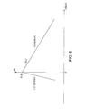
- An advantageous spreading function is that presented to the figure 5 . It is a triangular function whose first slope is + 27dB / Bark and -10dB / Bark for the second.
- ⁇ 1 ( j ) and ⁇ 2 ( j ) can be pre-calculated and stored.
- a first embodiment of the invention is described below for the allocation of bits in a hierarchical coder such as the G.729.1 encoder.
- bit allocation criterion is based here on the signal-to-mask ratio given by: 1 2 ⁇ log 2 ⁇ ⁇ 2 j M j
- the masking threshold is normalized by its value on the last subband of the low band.
- the definition of the term ip ( j ) , j 10, ..., 17, is changed.
- FIG 8 An illustration of the standardization of the masking threshold is given in figure 8 , showing the connection of the high band on which the masking (4-7 kHz) is applied to the low band (0-4 kHz).
- the standardization of the masking threshold can be rather carried out from the value of the band.
- these relations giving the normalization factor normfac or the masking threshold M ( j ) can be generalized to any number of sub-bands (different, in total, from eighteen) in high band (with a different number of eight), as in low band (with a different number of ten).
- the normalized masking threshold is not used to weight the energy in the definition of the perceptual importance, as in the first embodiment described above, but it serves to directly weight the high band signal before TDAC coding.
- This second embodiment is illustrated on the Figures 9A (for encoding) and 10A (for decoding).
- a variant of this second mode, which is the object of the present invention, in particular for the decoding performed, is illustrated on the Figures 9B (for encoding) and 10B (for decoding).
- the masking threshold is calculated (block 905 of the Figure 9A and block 906b of the Figure 9B ) from the unquantized spectral envelope.
- the peer decoder is shown in the figure 10A .
- the block 1002 is then performed as described in Ragot et al. supra.
- Block 1004 also performs a function similar to that of block 405 of the figure 4 .
- This second embodiment may be particularly advantageous, particularly in an implementation according to the 3GPP-AMR-WB + standard, which is the preferred context of the document Ragot et al. supra.
- the coded information remains the envelope of energy (rather than the masking threshold itself as on the Figures 9A and 10A ).
- the masking threshold is calculated and normalized (block 906b of the Figure 9B ) from the coded spectral envelope (block 905b).
- the masking threshold is calculated and standardized (block 1011b of the figure 10B ) from the decoded spectral envelope (block 1001b), the decoding of the envelope making it possible to perform a level adjustment (block 1010b of the figure 10B ) from the quantized values rms_q ( j ).
- a masking threshold is calculated for each sub-band, at least for the sub-bands of the high frequency band, this masking threshold being normalized to ensure spectral continuity between the subbands concerned.
- the calculation of the masking threshold is particularly advantageous when the signal to be coded is not tonal, in the first mode, as in the second embodiment, described above.
- the application of the spreading function B (v) results in a masking threshold very close to a tone a little more spread out in frequencies.
- the allocation criterion minimizing the masked coding noise ratio then gives a bit of bit allocation.
- the same is true for the direct weighting of the high band signal according to the second embodiment. It is therefore preferred, for a tonal signal, to use a bit allocation according to energy criteria.
- the invention is applied only if the signal to be encoded is not tonal.
- the bit relating to the mode of the coding of the spectral envelope indicates a "differential Huffman" mode or a "natural direct binary” mode.
- This mode bit can be interpreted as a tone detection, since, in general, a tonal signal leads to envelope coding by the "natural direct binary” mode, while most non-tonal signals, having a spectral dynamic more limited, lead to envelope coding by the "Differential Huffman" mode.
- the module 904 of the Figure 9A can, by calculating the spectral envelope, determine whether the signal is tonal or not and so Block 905 is bypassed if yes.
- the module 904 can make it possible to determine whether the signal is tonal or not and so bypass the block 907 in the affirmative.
- the figure 11 generalize the normalization of the masking curve (described in figure 8 ) in the case of super wide band coding.
- the signals in this embodiment are sampled at a frequency of 32 kHz (instead of 16 kHz) for a useful band of 50 Hz - 14 kHz.
- the masking curve log 2 [ M ( j )] is then defined at least for the sub-bands ranging from 7 to 14 kHz.
- the spectrum covering the band 50 Hz - 14 kHz is coded by subbands and the allocation of bits to each subband is made from the spectral envelope as in the G.729.1 encoder.
- a partial masking threshold can be calculated as previously described.
- the standardization of the masking threshold as illustrated on the figure 11 , so also generalizes to the case where the high band has more subbands or covers a wider frequency area than in G.729.1.
- a first T1 transform is applied to the time weighted difference signal.
- a second transform T2 is applied to the signal on the first high band between 4 and 7 kHz and a third transform T3 is applied to the signal on the second high band between 7 and 14 kHz.
- the invention is not limited to signals sampled at 16kHz. Its implementation is particularly advantageous also for signals sampled at higher frequencies, such as for the extension of the G.729.1 encoder to signals sampled not at 16 kHz but at 32 kHz, as described above. If the TDAC coding is generalized to such a frequency band (50 Hz - 14 kHz instead of 50 Hz - 7 kHz currently), the advantage provided by the invention will be really major.
- the invention also aims to improve the TDAC coding, in particular by applying a perceptual weighting of the high-bandwidth (4-14 kHz) while ensuring the spectral continuity between bands, this criterion being important for a joint coding of the band.
- first low band and the second high and extended band up to 14 kHz.
- the perceptual weighting in the low band is not necessary for the application of the invention.
- the present invention also relates to a first computer program, stored in a memory of an encoder of a telecommunication terminal and / or stored on a memory medium intended to cooperate with a reader of said encoder.
- This first program then comprises instructions for implementing the coding method defined above, when these instructions are executed by an encoder processor.
- the present invention also relates to an encoder comprising at least one memory storing this first computer program.
- FIGS. 6 , 9A and 9B may constitute flowcharts of this first computer program, or further illustrate the structure of such an encoder, according to different embodiments and variants.
- the present invention also relates to a second computer program, stored in a memory of a decoder of a telecommunication terminal and / or stored on a storage medium intended to cooperate with a reader of said decoder.
- This second program then comprises instructions for implementing the decoding method defined above, when these instructions are executed by a processor of the decoder.
- the present invention also relates to a decoder comprising at least one memory storing this second computer program.
- FIG. 7 , 10A , 10B may constitute flowcharts of this second computer program, or further illustrate the structure of such a decoder, according to different embodiments and variants.
Landscapes
- Engineering & Computer Science (AREA)
- Physics & Mathematics (AREA)
- Computational Linguistics (AREA)
- Signal Processing (AREA)
- Health & Medical Sciences (AREA)
- Audiology, Speech & Language Pathology (AREA)
- Human Computer Interaction (AREA)
- Acoustics & Sound (AREA)
- Multimedia (AREA)
- Spectroscopy & Molecular Physics (AREA)
- Compression, Expansion, Code Conversion, And Decoders (AREA)
Abstract
Description
La présente invention concerne un traitement de données sonores.The present invention relates to a sound data processing.
Ce traitement est adapté notamment à la transmission et/ou au stockage de signaux numériques tels que des signaux audiofréquences (parole, musique, ou autres).This processing is adapted in particular to the transmission and / or storage of digital signals such as audio-frequency signals (speech, music, or other).
Différentes techniques existent pour coder sous forme numérique un signal audiofréquences. Les techniques les plus courantes sont :
- les méthodes de codage de forme d'onde, telles que le codage MIC (pour "Modulation par Impulsions Codées") et MICDA (pour "Modulation par Impulsion et Codage Différentiel Adaptatif"), dits aussi "PCM" et "ADPCM" en anglais,
- les méthodes de codage paramétrique par analyse par synthèse comme le codage CELP (pour "Code Excited Linear Prediction"), et
- les méthodes de codage perceptuel en sous-bandes ou par transformée.
- waveform coding methods, such as MIC (for "Coded Pulse Modulation") and ADPCM (for "Pulse Modulation and Adaptive Differential Coding") coding, also known as "PCM" and "ADPCM" in English ,
- parametric coding methods using synthetic analysis such as Code Excited Linear Prediction (CELP), and
- perceptual encoding methods in subbands or by transform.
Ces techniques traitent le signal d'entrée de façon séquentielle échantillon par échantillon (MIC ou MICDA) ou par blocs d'échantillons dits "trames" (CELP et codage par transformée).These techniques treat the input signal sequentially sample by sample (MIC or ADPCM) or sample blocks called "frames" (CELP and transform coding).
On rappelle rapidement qu'un signal sonore tel qu'un signal de parole peut être prédit à partir de son passé récent (par exemple de 8 à 12 échantillons à 8 kHz) au moyen de paramètres évalués sur des fenêtres courtes (10 à 20 ms dans cet exemple). Ces paramètres de prédiction à court terme, représentatifs de la fonction de transfert du conduit vocal (par exemple pour prononcer des consonnes), sont obtenus par des méthodes d'analyse LPC (pour "Linear Prediction Coding"). On met en oeuvre aussi une corrélation à plus long terme pour déterminer des périodicités de sons voisés (par exemple les voyelles) dues à la vibration des cordes vocales. Il s'agit donc de déterminer au moins la fréquence fondamentale du signal voisé qui varie typiquement de 60 Hz (voix grave) à 600 Hz (voix aiguë) selon les locuteurs. On détermine alors, par une analyse LTP (pour "Long Term Prediction"), les paramètres LTP d'un prédicteur à long terme, et en particulier l'inverse de la fréquence fondamentale, appelée souvent "période de pitch". On définit alors le nombre d'échantillons dans une période de pitch par le rapport Fe/F0 (ou sa partie entière), où :
- Fe est la cadence d'échanlillonnage, et
- F0 est la fréquence fondamentale.
- F e is the sampling rate, and
- F 0 is the fundamental frequency.
On retiendra donc que les paramètres de prédiction à long terme LTP, dont la période de pitch, représentent la vibration fondamentale du signal de parole (lorsqu'il est voisé), tandis que les paramétres de prédiction à court terme LPC représentent l'enveloppe spectrale de ce signal.We therefore note that the LTP long-term prediction parameters, including the pitch period, represent the fundamental vibration of the speech signal (when it is voiced), while the LPC short-term prediction parameters represent the spectral envelope. of this signal.
Dans certains codeurs, l'ensemble de ces paramètres LPC et LTP, résultant donc d'un codage de parole, peuvent être transmis par blocs vers un décodeur homologue, via un ou plusieurs réseaux de télécommunication, pour restituer ensuite le signal de parole initial.In some coders, all of these LPC and LTP parameters, thus resulting from a speech coding, can be transmitted in blocks to a peer decoder, via one or more telecommunication networks, to then restore the initial speech signal.
En codage de parole conventionnel, le codeur génère un flux binaire à débit fixe. Cette contrainte de débit simplifie la mise en oeuvre et l'utilisation du codeur et du décodeur. Des exemples de tels systèmes sont le codage normalisé UIT-T G.711 à 64 kbit/s, le codage nomalisé UIT-T G.729 à 8 kbit/s ou le codage GSM-EFR à 12,2 kbit/s.In conventional speech coding, the encoder generates a fixed rate bit stream. This flow constraint simplifies the implementation and use of the encoder and the decoder. Examples of such systems are the ITU-T G.711 64 kbit / s standard coding, the 8 kbit / s ITU-T G.729 coding or the 12.2 kbit / s GSM-EFR coding.
Dans certaines applications (comme la téléphonie mobile ou la voix sur IP pour « Internet Protocol »), il est préférable de générer un flux binaire à débit variable. Les valeurs du débit sont prises dans un ensemble prédéfini. Une telle technique de codage, dite « multi-débits » s'avère donc plus flexible qu'une technique de codage à débit fixe.In some applications (such as mobile telephony or VoIP for "Internet Protocol"), it is best to generate a variable rate bit stream. Flow values are taken in a predefined set. Such a coding technique, called "multi-rate" is therefore more flexible than a fixed rate coding technique.
On peut distinguer plusieurs techniques de codage multi-débits :
- le codage multi-modes contrôlé par la source et/ou le canal, mis en oeuvre notamment dans les codeurs 3GPP AMR-NB, 3GPP AMR-WB, ou 3GPP2 VMR-WB,
- le codage hiérarchique (ou codage "scalable") qui génère un flux binaire dit « hiérarchique » car il comprend un débit coeur et une ou plusieurs couche(s) d'amélioration (le codage normalisé selon G.722 à 48, 56 et 64 kbit/s étant typiquement scalable en débit, tandis que les codecs UIT-T G.729.1 et MPEG-4 CELP sont scalables à la fois en débit et en largeur de bande),
- le codage à descriptions multiples, décrit notamment dans :
- "
A multiple description speech coder based on AMR-WB for mobile ad hoc networks", H. Dong, A. Gersho, J.D. Gibson, V. Cuperman, ICASSP, p. 277-280, vol.1 (Mai 2004
- "
- multi-mode coding controlled by the source and / or the channel, implemented in particular in 3GPP AMR-NB, 3GPP AMR-WB or 3GPP2 VMR-WB coders,
- the hierarchical coding (or "scalable " coding) that generates a so-called "hierarchical" bitstream because it comprises a core rate and one or more layer (s) The G.722 standardized coding at 48, 56 and 64 kbit / s is typically bitrate scalable, while the ITU-T G.729.1 and MPEG-4 CELP codecs are scalable in both bitrate and bitrate. bandwidth),
- multi-description coding, described in particular in:
- "
A multiple description speech coder based on AMR-WB for mobile ad hoc networks ", H. Dong, A. Gersho, JD Gibson, V. Cuperman, ICASSP, pp. 277-280, vol.1 (May 2004
- "
On détaille ci-après le codage hiérarchique, ayant la capacité de fournir des débits variés, en répartissant les informations relatives à un signal audio à coder dans des sous-ensembles hiérarchisés, de telle sorte que ces informations puissent être utilisées par ordre d'importance sur le plan de la qualité de rendu audio. Le critère pris en compte pour déterminer l'ordre est un critère d'optimisation (ou plutôt de moindre dégradation) de la qualité du signal audio codé. Le codage hiérarchique est particulièrement adapté à la transmission sur des réseaux hétérogènes ou présentant des débits disponibles variables au cours du temps, ou encore à la transmission à destination de terminaux présentant des capacités variables.Hierarchical coding, having the capacity to provide varied bit rates, is described below by distributing the information relating to an audio signal to be coded in hierarchical subsets, so that this information can be used in order of importance. in terms of audio rendering quality. The criterion taken into account for determining the order is a criterion for optimizing (or rather reducing) the quality of the coded audio signal. Hierarchical coding is particularly suited to transmission over heterogeneous networks or having variable available rates over time, or to transmission to terminals with varying capacities.
Le concept de base du codage audio hiérarchique (ou "scalable") peut être décrit comme suit.The basic concept of hierarchical audio coding (or " scalable ") can be described as follows.
Le flux binaire comprend une couche de base et une ou plusieurs couches d'amélioration. La couche de base est générée par un codec à bas débit (fixe), qualifié de « codec coeur », garantissant la qualité minimale du codage. Cette couche doit être reçue par le décodeur pour maintenir un niveau de qualité acceptable. Les couches d'amélioration servent à améliorer la qualité. Il peut arriver toutefois qu'elles ne soient pas toutes reçues par le décodeur.The bit stream includes a base layer and one or more enhancement layers. The base layer is generated by a low-bandwidth codec (fixed), called a "codec heart", guaranteeing the minimum coding quality. This layer must be received by the decoder to maintain an acceptable level of quality. Improvement layers are used to improve quality. However, they may not all be received by the decoder.
L'intérêt principal du codage hiérarchique est qu'il permet alors une adaptation du débit par simple « troncature du flux binaire ». Le nombre de couches (c'est-à-dire le nombre de troncatures possibles du flux binaire) définit la granularité du codage. On parle de codage à « granularité forte » si le flux binaire comprend peu de couches (de l'ordre de 2 à 4) et de codage à « granularité fine » permet par exemple un pas de l'ordre de 1 à 2 kbit/s.The main advantage of hierarchical coding is that it allows an adaptation of the bit rate simply by " truncation of the bit stream ". The number of layers (i.e., the number of possible truncations of the bitstream) defines the granularity of the coding. We speaks of coding " strong granularity " if the bitstream comprises few layers (of the order of 2 to 4) and coding " fine granularity " allows for example a step of the order of 1 to 2 kbit / s .
On décrit plus particulièrement ci-après les techniques de codage scalable en débit et en largeur de bande, avec un codeur coeur de type CELP, en bande téléphonique et une ou plusieurs couche(s) d'amélioration en bande élargie. Un exemple de tels systèmes est donné dans la norme UIT-T G.729.1 de 8 à 32 kbit/s à granularité fine. L'algorithme de codage/décodage G.729.1 est résumé ci-après.Specifically described below are scalable scalability and bandwidth encoding techniques, with a CELP heart-coder, a telephone band, and one or more broadband enhancement layer (s). An example of such systems is given in the ITU-T G.729.1 8-32 kbit / s fine grain standard. The G.729.1 coding / decoding algorithm is summarized below.
Le codeur G.729.1 est une extension du codeur UIT-T G.729. Il s'agit d'un codeur hiérarchique à coeur G.729, modifié, produisant un signal dont la bande va de la bande étroite (50-4000 Hz) à la bande élargie (50-7000 Hz) à un débit de 8 à 32 kbit/s pour les services conversationnels. Ce codec est compatible avec les équipements de voix sur IP existants (la plupart étant équipés selon la norme G.729). Il convient d'indiquer enfin que la norme G.729.1 a été approuvée en mai 2006.The G.729.1 encoder is an extension of the ITU-T G.729 coder. It is a modified G.729 heart-coded core encoder producing a bandwidth ranging from narrowband (50-4000 Hz) to wideband (50-7000 Hz) at a rate of 8 to 32 kbit / s for conversational services. This codec is compatible with existing VoIP devices (most of which are equipped according to G.729). Finally, it should be noted that G.729.1 was approved in May 2006.
Le codeur G.729.1 est schématisé sur la
La bande basse est prétraitée par un filtre passe-haut éliminant les composantes en dessous de 50 Hz (bloc 104), pour obtenir le signal SLB , avant codage CELP en bande étroite (bloc 105) à 8 et 12 kbit/s. Ce filtrage passe-haut tient compte du fait que la bande utile est définie comme couvrant l'intervalle 50-7000 Hz. Le codage CELP en bande étroite est un codage CELP en cascade comprenant comme premier étage un codage G.729 modifié sans filtre de prétraitement et comme deuxième étage un dictionnaire CELP fixe supplémentaire.The low band is pretreated with a high-pass filter eliminating the components below 50 Hz (block 104), to obtain the signal S LB , before CELP coding in narrow band (block 105) at 8 and 12 kbit / s. This high-pass filtering takes into account that the Useful band is defined as covering the range 50-7000 Hz. The narrow-band CELP coding is a cascaded CELP coding comprising as a first stage a modified G.729 coding without pre-processing filter and as a second stage an additional fixed CELP dictionary.
La bande haute est d'abord prétraitée (bloc 106) pour compenser le repliement dû au filtre passe-haut (bloc 102) combiné avec la décimation (bloc 103). La bande haute est ensuite fïltrée par un filtre passe-bas (bloc 107) éliminant les composantes entre 3000 et 4000 Hz de la bande haute (c'est-à-dire les composantes entre 7000 et 8000 Hz dans le signal original) pour obtenir le signal SHB . Une extension de bande (bloc 108) est ensuite réalisée.The high band is first pretreated (block 106) to compensate for the folding due to the high-pass filter (block 102) combined with the decimation (block 103). The high band is then filtered by a low pass filter (block 107) eliminating the components between 3000 and 4000 Hz from the high band (that is, the components between 7000 and 8000 Hz in the original signal) to obtain the signal S HB . A band extension (block 108) is then performed.
Une particularité importante de l'encodeur G.729.1 selon la
Des paramètres supplémentaires peuvent être transmis par le bloc 111 à un décodeur homologue, ce bloc 111 réalisant un traitement dit « FEC » pour « Frame Erasure Concealment », en vue de reconstituer d'éventuelles trames effacées.Additional parameters can be transmitted by the
Les différents flux binaires générés par les blocs de codage 105, 108, 110 et 111 sont enfin multiplexés et structurés en un train binaire hiérarchique dans le bloc de multiplexage 112. Le codage est réalisé par blocs d'échantillons (ou trames) de 20 ms, soit 320 échantillons par trame.The different bitstreams generated by the coding blocks 105, 108, 110 and 111 are finally multiplexed and structured into a hierarchical bit stream in the
Le codec G.729.1 a donc une architecture en trois étapes de codage comprenant :
- le codage CELP en cascade,
- l'extension de bande paramétrique
par le module 108, de type TDBWE (pour « Time Domain Bandwidth Extension »), et - un codage prédictif par transformée TDAC, appliqué après une transformation de type MDCT (pour « Modified Discrete Cosine Transform » ou « transformation en cosinus discrète modifiée »).
- cascading CELP coding,
- the parametric band extension by the
module 108, of the TDBWE (for "Time Domain Bandwidth Extension") type, and - a TDAC transform predictive coding, applied after an MDCT (Modified Discrete Cosine Transform) transformation.
Le décodeur homologue selon la norme G.729.1 est illustré sur la
Le flux binaire des couches à 8 et 12 kbit/s est utilisé par le décodeur CELP (bloc 201) pour générer la synthèse en bande étroite (0-4000 Hz). La portion du flux binaire associée à la couche à 14 kbit/s est décodée par le module d'extension de bande (bloc 202). La portion du flux binaire associée aux débits supérieurs à 14 kbit/s est décodée par le module TDAC (bloc 203). Un traitement des pré-échos et post-échos est réalisé par les blocs 204 et 207 ainsi qu'un enrichissement (bloc 205) et un post-traitement de la bande basse (bloc 206).The bit stream of the 8 and 12 kbit / s layers is used by the CELP decoder (block 201) to generate the narrow-band synthesis (0-4000 Hz). The portion of the bit stream associated with the 14 kbit / s layer is decoded by the tape extension module (block 202). The portion of the bit stream associated with data rates greater than 14 kbit / s is decoded by the TDAC module (block 203). Pre-echo and post-echo processing is performed by
Le signal de sortie en bande élargie ŝwb , échantillonné à 16 kHz, est obtenu par l'intermédiaire du banc de filtres QMF de synthèse (blocs 209, 210, 211, 212 et 213) intégrant le repliement inverse (bloc 208).The broadband output signal ŝ wb , sampled at 16 kHz, is obtained via the QMF synthesis filter bank (
La description de la couche de codage par transformée est détaillée ci-après.The description of the transform coding layer is detailed below.
Le codage par transformée de type TDAC dans le codeur G.729.1 est illustré sur la
Le filtre WLB (z) (bloc 300) est un filtre de pondération perceptuelle, avec compensation de gain, appliqué au signal d'erreur en bande basse dLB . Des transformées MDCT sont ensuite calculées (bloc 301 et 302) pour obtenir :
- le spectre MDCT

- le spectre MDCT SHB du signal original de la bande haute.
- the MDCT spectrum
- the MDCT spectrum S HB of the original signal to the high band.
Ces transformées MDCT (blocs 301 et 302) s'appliquent à 20 ms de signal échantillonné à 8 kHz (160 coefficients). Le spectre Y(k) issu du bloc 303 de fusion comprend ainsi 2 x 160, soit 320 coefficients. Il est défini comme suit : ![]()
![]()
Ce spectre est divisé en dix-huit sous-bandes, une sous-bande j étant affectée d'un nombre de coefficients noté nb_coef(j). Le découpage en sous-bandes est spécifié dans le tableau 1 ci-après.This spectrum is divided into eighteen sub-bands, a sub-band j being assigned a number of coefficients noted nb_coef ( j ). The subband splitting is specified in Table 1 below.
Ainsi, une sous-bande j comprend les coefficients Y(k) avec sb_bound(j) ≤ k < sb_bound(j + 1).
L'enveloppe spectrale {log_rms(j)} j=0,...,17 est calculée dans le bloc 304 suivant la formule : 
où εrms = 2-24.The spectral envelope {log_ rms (j)} j = 0, ..., 17 is calculated in
where ε rms = 2 -24 .
L'enveloppe spectrale est codée à débit variable dans le bloc 305. Ce bloc 305 produit des valeurs quantifiée, entières, notées rms_index(j) (avec j=0,..., 17), obtenues par simple quantification scalaire : ![]()
où la notation « round » désigne l'arrondi à l'entier le plus proche, et avec la contrainte : ![]()
Cette valeur quantifiée rms _index(j) est transmise au bloc d'allocation de bits 306.The spectral envelope is coded at a variable rate in ![]()
where the notation "round" designates the rounding to the nearest integer, and with the constraint: ![]()
This quantized value rms _index ( j ) is transmitted to the
Le codage de l'enveloppe spectrale, lui-même, est effectué encore par le bloc 305, séparément pour la bande basse (rms_index(j), avec j=0,...,9) et pour la bande haute (rms_index(j), avec j=10,...,17). Dans chaque bande, deux types de codage peuvent être choisis selon un critère donné, et, plus précisément, les valeurs rms_index(j) :
- peuvent être codées par codage dit « de Huffman différentiel »,
- ou peuvent être codées par codage binaire naturel.
- can be coded by "differential Huffman" coding,
- or can be encoded by natural binary coding.
Le nombre de bits alloués à chaque sous-bande pour sa quantification est déterminé au bloc 306 à partir de l'enveloppe spectrale quantifiée issue du bloc 305. L'allocation des bits effectuée minimise l'erreur quadratique tout en respectant la contrainte d'un nombre de bits entier alloué par sous-bande et d'un nombre de bits maximum à ne pas dépasser. Le contenu spectral des sous-bandes est ensuite codé par quantification vectorielle sphérique (bloc 307).The number of bits allocated to each sub-band for its quantization is determined in
Les différents flux binaires générés par les blocs 305 et 307 sont ensuite multiplexés et structurés en un train binaire hiérarchique au bloc de multiplexage 308.The different bit streams generated by the
L'étape de décodage par transformée de type TDAC dans le décodeur G.729.1 est illustrée sur la
De façon symétrique à l'encodeur (![]()
![]()
Le contenu spectral de chacune des sous-bandes est retrouvé par quantification vectorielle sphérique inverse (bloc 403). Les sous-bandes non transmises, faute de « budget » de bits suffisant, sont extrapolées (bloc 404) à partir de la transformée MDCT du signal en sortie du bloc d'extension de bande (bloc 202 de la
Après mise à niveau de ce spectre (bloc 405) en fonction de l'enveloppe spectrale et post-traitement (bloc 406), le spectre MDCT est séparé en deux (bloc 407) :
- avec 160 premiers coefficients correspondant au spectre

- et 160 coefficients suivants correspondant au spectre ŜHB du signal original décodé en bande haute.
- with 160 first coefficients corresponding to the spectrum
- and 160 subsequent coefficients corresponding to the spectrum Ŝ HB of the original decoded high band signal.
Ces deux spectres sont transformés en des signaux temporels par transformée MDCT inverse, notée IMDCT (blocs 408 et 410), et la pondération perceptuelle inverse (filtre noté WLB (z)-1) est appliquée au signal ![]()
![]()
On décrit plus particulièrement ci-après l'allocation de bits aux sous-bandes (bloc 306 de la
Les blocs 306 et 402 réalisent une opération identique à partir des valeurs rms_index(j),j=0,...,17. On se contente donc par la suite de décrire uniquement le fonctionnement du bloc 306.
Le but de l'allocation binaire est de répartir entre chacune des sous-bandes un certain budget de bits (variable) noté nbits_VQ, avec :![]()
![]()
Le résultat de l'allocation est le nombre entier de bits, noté nbit(j) (avec j=0,...,17), alloués à chacune des sous-bande avec comme contrainte globale : 
Dans la norme G.729.1, les valeurs nbit(j) (j=0,...,17), sont de plus contraintes par le fait que nbit(j) doit être choisi parmi un jeu de valeurs réduit spécifié au tableau 2 ci-après.
L'allocation dans la norme G.729.1 repose sur une "importance perceptuelle" par sous-bande liée à l'énergie de la sous-bande, notée ip(j) (j=0..17), définie comme suit : 
où offset = -2.The allocation in G.729.1 is based on a "perceptual importance" per subband related to the energy of the subband, denoted ip ( j ) ( j = 0..17), defined as follows:
where offset = -2.
Puisque les valeurs rms_q(j) = 2½ rms_index(j), cette formule se simplifie sous la forme : 
A partir de l'importance perceptuelle de chaque sous-bande, l'allocation nbit(j) est calculée comme suit : 
où λ opt est un paramètre optimisé par dichotomie.Since the rms values _ q ( j ) = 2 ½ rms _ index ( j ) , this formula is simplified as:
From the perceptual importance of each sub-band, the allocation nbit ( j ) is calculated as follows:
where λ opt is a parameter optimized by dichotomy.
On décrit plus en détail maintenant l'incidence de la pondération perceptuelle (filtrage du bloc 300) sur l'allocation de bits (bloc 306) du codeur par transformée TDAC.The incidence of perceptual weighting (filtering of block 300) on the bit allocation (block 306) of the TDAC transform coder is described in more detail below.
Dans la norme G.729.1, le codage TDAC utilise le filtre WLB (z) de pondération perceptuelle dans la bande basse (bloc 300), comme indiqué ci-avant. En substance, le filtrage de pondération perceptuelle permet de mettre en forme le bruit de codage. Le principe de ce filtrage est d'exploiter le fait qu'il est possible d'injecter plus de bruit dans les zones de fréquences où le signal original a une forte énergie.In the G.729.1 standard, the TDAC coding uses the perceptual weighting W LB ( z ) filter in the low band (block 300), as indicated above. In essence, perceptual weighting filtering allows you to format the coding noise. The principle of this filtering is to exploit the fact that it is possible to inject more noise in the frequency zones where the original signal has a high energy.
Les filtres de pondération perceptuelle les plus couramment utilisés en codage CELP en bande étroite sont de la forme Â(z/γ1)/Â(z/γ2) où 0 ≤ γ2 ≤ γ1 < 1 et Â(z) représente un spectre de prédiction linéaire (LPC). L'analyse par synthèse en codage CELP revient ainsi à minimiser l'erreur quadratique dans un domaine de signal pondéré perceptuellement par ce type de filtre.The most common perceptual weighting filters used in narrow-band CELP coding are of the form  (z / γ1) /  (z / γ2) where 0 ≤ γ2 ≤ γ1 <1 and  (z) represents a prediction spectrum linear (LPC). CELP coding synthesis analysis Thus, it amounts to minimizing the quadratic error in a perceptually weighted signal domain by this type of filter.
Cependant, pour assurer la continuité spectrale lorsque les spectres ![]()

avec γ1 = 0,96, γ2 = 0,6 et 
![]()
with γ 1 = 0.96, γ 2 = 0.6 and
Le facteur fac permet d'assurer à la jonction des bandes basse et haute (4 kHz) un gain du filtre à 1 à 4 kHz. Il est important de noter que, dans le codage TDAC selon la norme G.729.1, le codage ne repose que sur un critère énergétique.The fac factor makes it possible to ensure at the junction of the low and high bands (4 kHz) a gain of the filter at 1 to 4 kHz. It is important to note that in the G.729.1 TDAC coding, the coding is based on an energetic criterion only.
Dans la norme G.729.1, l'encodeur TDAC traite conjointement :
- le signal différence, entre la bande basse originale et la synthèse CELP, filtré perceptuellement par un filtre du type Â(z/γ1)/Â(z/γ2) compensé en gain (assurant une continuité spectrale), et
- la bande haute qui contient le signal bande haute original.
- the difference signal, between the original low band and the CELP synthesis, perceptually filtered by a gain-compensated λ (z / γ1) / λ (z / γ2) filter (ensuring spectral continuity), and
- the high band which contains the original high band signal.
Le codage conjoint de ces deux signaux est réalisé dans le domaine MDCT suivant le critère de l'erreur quadratique. Ainsi, la bande haute est codée suivant des critères énergétiques, ce qui est sous-optimal (au sens « perceptuel » du terme).The joint coding of these two signals is carried out in the MDCT domain according to the criterion of the quadratic error. Thus, the high band is coded according to energy criteria, which is suboptimal (in the "perceptual" sense of the term).
De façon plus générale encore, on pourra considérer le cas d'un codage dans plusieurs bandes, un filtre de pondération perceptuelle étant appliqué au signal d'au moins une bande dans le domaine temporel, et l'ensemble des sous-bandes étant codées conjointement par codage par transformée. Si l'on veut appliquer la pondération perceptuelle dans le domaine des fréquences, il se pose alors le problème de la continuité et de l'homogénéité des spectres entre sous-bandes.More generally, the case of multi-band coding may be considered, a perceptual weighting filter being applied to the signal of at least one band in the time domain, and the set of subbands being coded together. by transform coding. If we want to apply the perceptual weighting in the frequency domain, then there is the problem of continuity and homogeneity of the spectra between subbands.
La présente invention vient améliorer la situation.The present invention improves the situation.
Elle propose à cet effet un procédé de codage d'un signal en plusieurs sous-bandes, dans lequel au moins une première et une deuxième sous-bande, adjacentes, sont codées par transformée.It proposes for this purpose a method of coding a signal in several sub-bands, in which at least one first and one second sub-band, adjacent, are encoded by transform.
Au sens de l'invention, pour appliquer une pondération perceptuelle, dans le domaine transformée, au moins à la deuxième sous-bande, le procédé comporte :
- une détermination d'au moins un seuil de masquage fréquentiel à appliquer sur la deuxième sous-bande, et
- une normalisation dudit seuil de masquage pour assurer une continuité spectrale entre lesdites première et deuxième sous-bandes.
- a determination of at least one frequency masking threshold to be applied on the second subband, and
- normalizing said masking threshold to provide spectral continuity between said first and second subbands.
La présente invention propose donc de calculer une pondération perceptuelle fréquentielle, utilisant un seuil de masquage, sur une partie seulement de la bande de fréquences (au moins sur la « deuxième sous-bande » précitée) et d'assurer la continuité spectrale avec au moins une autre bande de fréquences (au moins la « première sous-bande » précitée) en normalisant le seuil de masquage sur le spectre couvrant ces deux bandes de fréquences.The present invention therefore proposes to calculate a frequency perceptual weighting, using a masking threshold, on only a part of the frequency band (at least on the "second subband" mentioned above) and to ensure spectral continuity with at least another frequency band (at least the aforementioned "first sub-band") by normalizing the masking threshold on the spectrum covering these two frequency bands.
Dans un premier mode d'application de l'invention, dans lequel un nombre de bits à allouer à chaque sous-bande est déterminé à partir d'une enveloppe spectrale, l'allocation des bits pour la deuxième sous-bande au moins est déterminée en outre en fonction d'un calcul de courbe de masquage normalisé, appliqué au moins à la deuxième sous-bande.In a first embodiment of the invention, in which a number of bits to be allocated to each sub-band is determined from a spectral envelope, the allocation of the bits for the second sub-band at least is determined furthermore according to a standardized masking curve calculation, applied at least to the second sub-band.
Ainsi, au lieu de prévoir, dans ce premier mode de réalisation, une allocation de bits basée sur des critères uniquement énergétiques, l'application de l'invention permet d'aflecter les bits aux sous-bandes qui nécessitent le plus de bits selon un critère perceptuel. On applique alors, au sens de ce premier mode de réalisation, une pondération perceptuelle fréquentielle par masquage d'une partie de la bande audio, de façon à améliorer la qualité audio en optimisant en particulier la répartition des bits entre sous-bandes suivant des critères perceptuels.Thus, instead of providing, in this first embodiment, a bit allocation based on purely energetic criteria, the application of the invention makes it possible to transmit the bits to the sub-bands that require the most bits according to a perceptual criterion. For the purposes of this first embodiment, perceptual frequency weighting is then applied by masking a part of the audio band, so as to improve the audio quality by optimizing in particular the distribution of bits between subbands according to criteria. perceptual.
Dans un deuxième mode d'application de l'invention, le signal transformé, dans la deuxième sous-bande, est pondéré par un facteur proportionnel à la racine carrée du seuil de masquage normalisé pour la deuxième sous-bande.In a second embodiment of the invention, the transformed signal in the second subband is weighted by a factor proportional to the square root of the normalized masking threshold for the second subband.
Dans ce second mode, le seuil de masquage normalisé n'est pas utilisé pour l'allocation des bits aux sous-bandes comme dans le premier mode d'application ci-avant, mais il peut servir avantageusement à pondérer directement le signal de la deuxième sous-bande au moins, dans le domaine transformé.In this second mode, the normalized masking threshold is not used for the allocation of the bits to the subbands as in the first application mode above, but it can advantageously be used to directly weight the signal of the second sub-band at least in the transformed domain.
La présente invention s'applique avantageusement, mais non limitativement, à un codage par transformée de type TDAC dans un codeur global selon la norme G.729.1, la première sous-bande étant incluse dans une bande de basses fréquences, tandis que la deuxième sous-bande est incluse dans une bande de hautes fréquences qui peut s'étendre jusqu'à 7000 Hz, voire plus (typiquement jusqu'à 14 kHz) en extension de bande. L'application de l'invention peut consister alors à prévoir une pondération perceptuelle pour la bande haute tout en assurant la continuité spectrale avec la bande basse.The present invention is advantageously, but not exclusively, applied to a TDAC-type transform coding in a global encoder according to the G.729.1 standard, the first subband being included in a low frequency band, whereas the second subband is included in a low frequency band, while the second subband is included in a low frequency band. -band is included in a high frequency band that can extend up to 7000 Hz, or even more (typically up to 14 kHz) in band extension. The application of the invention may then consist in providing a perceptual weighting for the high band while ensuring spectral continuity with the low band.
On rappelle que dans ce type de codeur global à structure hiérarchique, le codage par transformée intervient dans une couche supérieure d'un codeur hiérarchique global. Avantageusement :
- la première sous-bande comporte alors un signal issu d'un codage de coeur du codeur hiérarchique,
- et la deuxième sous-bande comporte un signal original.
- the first subband then comprises a signal resulting from a core coding of the hierarchical coder,
- and the second subband has an original signal.
Comme dans le codeur G.729.1, le signal issu du codage de coeur peut être pondéré perceptuellement et la mise en oeuvre de l'invention est avantageuse dans le sens où toute la bande spectrale peut finalement être pondérée perceptuellement.As in the G.729.1 coder, the signal from the core coding can be perceptually weighted and the implementation of the invention is advantageous in the sense that the entire spectral band can finally be perceptually weighted.
Comme dans le codeur G.729.1, le signal issu du codage de coeur peut être un signal représentatif d'une différence entre un signal original et une synthèse de ce signal original (appelé « signal différence » ou encore « signal d'erreur »). On verra en effet, en référence à la
La présente invention vise aussi un procédé de décodage, homologue du procédé de codage défini ci-avant, dans lequel au moins une première et une deuxième sous-bande, adjacentes, sont décodées par transformée. Pour appliquer une pondération perceptuelle, dans le domaine transformé, au moins à la deuxième sous-bande, le procédé de décodage comporte alors :
- une détermination d'au moins un seuil de masquage fréquentiel à appliquer sur la deuxième sous-bande, à partir d'une enveloppe spectrale décodée, et
- une normalisation dudit seuil de masquage pour assurer une continuité spectrale entre lesdites première et deuxième sous-bandes.
- a determination of at least one frequency masking threshold to be applied on the second subband, from a decoded spectral envelope, and
- normalizing said masking threshold to provide spectral continuity between said first and second subbands.
Un premier mode d'application du décodage, homologue du premier mode d'application du codage défini ci-avant, vise l'allocation de bits au décodage et un nombre de bits à allouer à chaque sous-bande est déterminé à partir d'un décodage d'enveloppe spectrale. Selon une mise en oeuvre de l'invention, l'allocation des bits pour la deuxième sous-bande au moins est déterminée en outre en fonction d'un calcul de courbe de masquage normalisé, appliqué au moins à la deuxième sous-bande.A first decoding application mode, homologous to the first application mode of the coding defined above, aims at the allocation of bits to the decoding and a number of bits to be allocated to each subband is determined from a decoding spectral envelope. According to one implementation of the invention, the bit allocation for the at least second subband is further determined according to a normalized masking curve calculation applied at least to the second subband.
Un deuxième mode d'application du décodage au sens de l'invention consiste à pondérer le signal transformé dans la deuxième sous-bande, par la racine carrée du seuil de masquage normalisé. Ce mode de réalisation sera décrit en détail en référence à la
D'ailleurs, d'autres avantages et caractéristiques de l'invention apparaîtront à l'examen de la description détaillée, donnée à titre d'exemple ci-après, et des dessins annexés sur lesquels, outre les
- la
figure 5 illustre une fonction d'étalement avantageuse pour le masquage au sens de l'invention, - la
figure 6 illustre, à titre de comparaison avec lafigure 3 , la structure d'un encodage TDAC utilisant un calcul de courbe de masquage 606 pour l'allocation de bits selon un premier mode d'application de l'invention, - la
figure 7 illustre, à titre de comparaison avec lafigure 4 , la structure d'un décodage TDAC homologue de lafigure 6 , utilisant un calcul de courbe de masquage 702 selon le premier mode d'application de l'invention, - la
figure 8 illustre une normalisation de la courbe de masquage, dans une première forme de réalisation où la fréquence d'échantillonnage est de 16 kHz et le masquage de l'invention appliqué pour la bande haute 4-7 kHz, - la
figure 9A illustre la structure d'un encodage TDAC modifiée, avec pondération directement du signal dans les hautes fréquences 4-7 kHz dans un deuxième mode d'application de l'invention, et codage du seuil de masquage normalisé, - la
figure 9B illustre la structure d'un encodage TDAC dans une variante du deuxième mode d'application illustré sur lafigure 9A , avec ici un codage de l'enveloppe spectrale, - la
figure 10A illustre la structure d'un décodage TDAC homologue de lafigure 9A , selon le deuxième mode d'application de l'invention, - la
figure 10B illustre la structure d'un décodage TDAC homologue de lafigure 9B , selon le deuxième mode d'application de l'invention, avec ici un calcul du seuil de masquage au décodage, - la
figure 11 illustre la normalisation de la courbe de masquage en bande super-élargie dans une deuxième forme de réalisation de l'invention où la fréquence d'échantillonnage est de 32 kHz et le masquage de l'invention appliqué pour la bande haute élargie de 4 à 14 kHz, et - la
figure 12 illustre la puissance spectrale, en sortie de codage CELP, du signal de différence DLB (en trait plein) et du signal original SLB (en traits pointillés).
- the
figure 5 illustrates an advantageous spreading function for masking within the meaning of the invention, - the
figure 6 illustrates, for comparison with thefigure 3 , the structure of a TDAC encoding using amasking curve calculation 606 for the allocation of bits according to a first embodiment of the invention, - the
figure 7 illustrates, for comparison with thefigure 4 , the structure of a TDAC decode homologous to thefigure 6 using amasking curve calculation 702 according to the first embodiment of the invention, - the
figure 8 illustrates a normalization of the masking curve, in a first embodiment where the sampling frequency is 16 kHz and the masking of the invention applied for the high band 4-7 kHz, - the
Figure 9A illustrates the structure of a modified TDAC encoding, with directly weighting of the signal in the high frequencies 4-7 kHz in a second embodiment of the invention, and coding of the standardized masking threshold, - the
Figure 9B illustrates the structure of a TDAC encoding in a variant of the second mode of application illustrated on theFigure 9A , here with a coding of the spectral envelope, - the
figure 10A illustrates the structure of a TDAC decoding peer of theFigure 9A according to the second embodiment of the invention, - the
figure 10B illustrates the structure of a TDAC decoding peer of theFigure 9B according to the second embodiment of the invention, with here a calculation of the decoding masking threshold, - the
figure 11 illustrates the normalization of the super-wideband masking curve in a second embodiment of the invention where the sampling frequency is 32 kHz and the masking of the invention applied for the broadband widened from 4 to 14 kHz, and - the
figure 12 illustrates the spectral power, at the output of the CELP coding, of the difference signal D LB (in solid lines) and of the original signal S LB (in dashed lines).
On décrit ci-après une application de l'invention qui s'avère avantageuse mais non limitative dans un encodeur/décodeur selon la norme G.729.1 décrit précédemment en référence aux
Auparavant toutefois, les notions de compensation de gain en filtrage perceptuel et de masquage fréquentiel sont présentées ci-après, pour mieux appréhender le principe de l'invention.Previously, however, the notions of gain compensation perceptual filtering and frequency masking are presented below, to better understand the principle of the invention.
L'invention apporte un perfectionnement à la pondération perceptuelle réalisée dans le codeur par transformée en exploitant l'effet de masquage connu sous le nom de « masquage simultané » ou « masquage fréquentiel ».The invention provides an improvement to the perceptual weighting performed in the transform coder by exploiting the masking effect known as "simultaneous masking" or "frequency masking".
Cette propriété correspond à la modification du seuil d'audition en présence d'un son dit « masquant ». Ce phénomène est observé typiquement lorsque, par exemple, on essaie de tenir une discussion avec du bruit ambiant, par exemple en pleine rue et que le bruit d'un véhicule vient « masquer » la voix d'un locuteur.This property corresponds to the modification of the hearing threshold in the presence of a so-called "masking" sound. This phenomenon is observed typically when, for example, one tries to hold a discussion with ambient noise, for example in the street and that the noise of a vehicle comes to "hide" the voice of a speaker.
Un exemple d'utilisation du masquage dans un codec audio peut être trouvé dans le document Mahieux et al. :
- "
High-quality audio transform coding at 64 kbps", Y. Mahieux, J.P. Petit, IEEE Transactions on Communications, Volume 42, no. 11, Pages: 3010 - 3019 (Novembre 1994
- "
High-quality audio transform coding at 64 kbps ", Mahieux Y., JP Petit, IEEE Transactions on Communications, Volume 42, No. 11, Pages: 3010-3019 (November 1994)
Dans ce document, un seuil de masquage approximatif est calculé pour chaque raie du spectre. Ce seuil est celui au-dessus duquel la raie concernée est supposée audible. Le seuil de masquage est calculé à partir de la convolution du spectre du signal avec une fonction d'étalement B(v) modélisant l'effet de masquage d'un son (sinusoïde ou bruit blanc filtré) par un autre son (sinusoïde ou bruit blanc filtré).In this document, an approximate masking threshold is calculated for each spectrum line. This threshold is the one above which the line concerned is supposed to be audible. The masking threshold is calculated from the convolution of the signal spectrum with a spreading function B ( v ) modeling the masking effect of a sound (sinusoid or filtered white noise) by another sound (sinusoid or noise filtered white).
Un exemple d'une telle fonction d'étalement est présenté sur la 
Dans ce document, le calcul du seuil de masquage est effectué par sous-bande plutôt que par raie. Le seuil ainsi obtenu est utilisé pour pondérer perceptuellement chacune des sous-bandes. L'allocation des bits est ainsi effectuée, non pas en minimisant l'erreur quadratique mais en minimisant le rapport « bruit de codage à masque », le but étant de mettre en forme le bruit de codage de tel sorte qu'il soit inaudible (en dessous du seuil de masquage).An example of such a spreading function is presented on the
In this document, the calculation of the masking threshold is performed by subband rather than by line. The threshold thus obtained is used to perceptually weight each of the subbands. The allocation of the bits is thus performed, not by minimizing the square error but by minimizing the "mask-to-mask noise" ratio, the aim being to shape the coding noise so that it is inaudible ( below the masking threshold).
Bien entendu, d'autres modèles de masquage ont été encore proposés. Typiquement, la fonction d'étalement peut être fonction du niveau de la raie et/ou de la fréquence de la raie masquante. Une détection des « pics » peut aussi être mise en oeuvre.Of course, other masking models have been proposed. Typically, the spreading function may be a function of the level of the line and / or the frequency of the masking line. A detection of "peaks" can also be implemented.
Il convient d'indiquer que pour réduire la sous-optimalité du codage selon la norme G.729.1, on pourrait penser à intégrer une technique de masquage fréquentiel dans l'allocation des bits, de façon similaire à celle présentée dans le document Mahieux et al. Néanmoins, la nature hétérogène des deux signaux bande basse et bande haute ne permet pas d'appliquer directement la technique de masquage pleine bande de ce document. D'une part, le seuil de masquage pleine bande ne peut pas vraiment être calculé dans le domaine MDCT, car le signal bande basse n'est pas homogène à un signal « original ». D'autre part, appliquer un seuil de masquage sur toute la bande de fréquences reviendrait à pondérer une nouvelle fois le signal en bande basse qui est déjà pondérée par le filtre de type Â(z/γ1)/Â(z/γ2), la pondération supplémentaire par un seuil n'ayant alors aucun sens pour ce signal de bande basse.It should be noted that to reduce the under-optimality of coding according to G.729.1, one might consider integrating a frequency masking bit allocation, similar to that presented in Mahieux et al. Nevertheless, the heterogeneous nature of the two low-band and high-band signals does not make it possible to directly apply the full-band masking technique of this document. On the one hand, the full-band masking threshold can not really be calculated in the MDCT domain because the low band signal is not homogeneous with an "original" signal. On the other hand, applying a masking threshold over the entire frequency band would again weight the low band signal that is already weighted by the λ (z / γ1) / λ (z / γ2) type filter, the additional weighting by a threshold then having no meaning for this low band signal.
Une application de l'invention décrite ci-après permet d'améliorer le codage TDAC de l'encodeur selon la norme G.729.1, en particulier en appliquant une pondération perceptuelle de la bande haute (4 à 7 kHz) tout en assurant la continuité spectrale entre bandes basse et haute pour un codage satisfaisant et conjoint de ces deux bandes.An application of the invention described hereinafter makes it possible to improve the TDAC coding of the encoder according to the G.729.1 standard, in particular by applying a perceptual weighting of the high band (4 to 7 kHz) while ensuring the continuity spectral between low and high bands for a satisfactory and joint coding of these two bands.
Dans un encodeur et/ou un décodeur selon la norme G.729.1, perfectionnés par la mise en oeuvre de l'invention, seuls les codeur et décodeur TDAC sont modifiés, dans l'exemple décrit ci-après.In an encoder and / or a decoder according to the G.729.1 standard, improved by the implementation of the invention, only the TDAC coder and decoder are modified, in the example described below.
Le signal d'entrée est échantillonné à 16 kHz, de bande utile 50 Hz à 7 kHz. En pratique le codeur fonctionne toujours au débit maximal de 32 kbit/s, tandis que le décodeur peut recevoir le coeur (8 kbit/s), ainsi qu'une ou plusieurs couches d'amélioration (12 à 32 kbit/s par pas de 2 kbit/s), comme dans la norme G.729.1. Les codage et décodage ont la même architecture que celle présentée aux
Dans un premier mode de réalisation décrit ci-après en référence à la
De même, le décodeur TDAC modifié est présenté sur la
Les blocs 606 et 702 réalisent une opération identique à partir des valeurs rms_index(j), j=0,...,17. De même, les blocs 607 et 703 réalisent une opération identique à partir des valeurs log_mask(j) et rms_index(j), j=0,...,17.
Dans ce qui suit, on ne décrit donc que le fonctionnement des blocs 606 et 607.In what follows, only the operation of
Le bloc 606 calcule une courbe de masquage à partir de l'enveloppe spectrale quantifiée rms_ q(j) où j=0,...,17 est le numéro de la sous-bande.
Le seuil de masquage M(j) de la sous-bande j est défini par la convolution de l'enveloppe d'énergie σ̂2 (j) = rms_q(j)2×nb_coef(j), par une fonction d'étalement B(v) . Dans l'exemple de réalisation donné ici du codage TDAC dans l'encodeur G.729.1, ce masquage n'est effectué que sur la bande haute du signal, avec : 
- où vk est la fréquence centrale de la sous-bande k en Bark,
- le signe « × » désignant « multiplié par », avec la fonction d'étalement décrite ci-après.
- where v k is the central frequency of the sub-band k in Bark,
- the sign "×" denoting "multiplied by", with the spreading function described below.
En termes plus génériques, le seuil de masquage M(j), pour une sous-bande j, est donc défini par une convolution entre :
- une expression de l'enveloppe spectrale, et
- une fonction d'étalement faisant intervenir une fréquence centrale de la sous-bande j.
- an expression of the spectral envelope, and
- a spreading function involving a central frequency of the sub-band j .
Une fonction d'étalement avantageuse est celle présentée à la 
où ![]()
![]()
et ![]()

or ![]()
![]()
and ![]()
Les valeurs de Δ1(j) et Δ2(j) peuvent être pré-calculées et stockées.The values of Δ 1 ( j ) and Δ 2 ( j ) can be pre-calculated and stored.
On décrit ci-après un premier mode d'application de l'invention à l'allocation de bits dans un codeur hiérarchique tel que l'encodeur G.729.1.A first embodiment of the invention is described below for the allocation of bits in a hierarchical coder such as the G.729.1 encoder.
Le critère d'allocation de bits se fonde ici sur le rapport signal-à-masque donné par : 
La bande basse étant déjà filtrée perceptuellement, l'application du seuil de masquage est limitée à la bande haute. De manière à assurer la continuité spectrale entre le spectre en bande basse et celui en bande haute pondéré par le seuil de masquage et pour éviter de biaiser l'allocation binaire, le seuil de masquage est normalisé par sa valeur sur la dernière sous-bande de la bande basse.The low band is already filtered perceptually, the application of the masking threshold is limited to the high band. In order to ensure the spectral continuity between the low and high band spectrum weighted by the masking threshold and to avoid biasing the bit allocation, the masking threshold is normalized by its value on the last subband of the low band.
L'importance perceptuelle est donc redéfinie comme suit : 
où offset = -2 et normfac est un facteur de normalisation calculé suivant la relation : 
On note que l'importance perceptuelle ip(j), j=0,...,9, est identique à celle définie dans la norme G.729.1. Par contre, la définition du terme ip(j) , j=10,...,17, est changée.The perceptual importance is redefined as follows:
where offset = -2 and normfac is a normalization factor calculated according to the relation:
We note that the perceptual importance ip ( j ) , j = 0, ..., 9, is identical to that defined in the G.729.1 standard. On the other hand, the definition of the term ip ( j ) , j = 10, ..., 17, is changed.
L'importance perceptuelle redéfinie ci-dessus s'écrit maintenant : 
où log_ mask(j) = log2(M (j)) - normfac.
On comprendra que la deuxième ligne de l'accolade pour le calcul de l'importance perceptuelle est une expression de la mise en oeuvre de l'invention selon cette première application à l'allocation de bits dans un codage par transformée en tant que couche supérieure d'un codeur hiérarchique.The perceptual importance redefined above is now written:
where log_ mask ( j ) = log 2 ( M ( j )) - normfac .
It will be understood that the second line of the brace for calculating the perceptual importance is an expression of the implementation of the invention according to this first application to the allocation of bits in a transform coding as an upper layer a hierarchical coder.
Une illustration de la normalisation du seuil de masquage est donnée en
Les blocs 607 et 703 effectuent alors les calculs d'allocation de bits : ![]()
où λ opt est obtenu par dichotomie comme dans la norme G.729.1.![]()
where λ opt is obtained by dichotomy as in the G.729.1 standard.
La seule différence par rapport aux blocs 307 et 402 de l'art antérieur est donc la définition de l'importance perceptuelle ip(j) pour les sous-bandes de la bande haute.The only difference with respect to
Dans une variante de ce mode de réalisation où la normalisation du seuil de masquage s'effectue par rapport à sa valeur sur la dernière sous-bande de la bande basse, la normalisation du seuil de masquage peut être plutôt réalisée à partir de la valeur du seuil de masquage dans la première sous-bande de la bande haute, comme suit : 
Dans une autre variante encore, le seuil de masquage peut être calculé sur l'ensemble de la bande de fréquences, avec : 
Le seuil de masquage est ensuite appliqué uniquement à la bande haute après normalisation du seuil de masquage par sa valeur sur la dernière sous-bande de la bande basse: 

The masking threshold is then applied only to the high band after normalization of the masking threshold by its value on the last subband of the low band:
Bien entendu, ces relations donnant le facteur de normalisation normfac ou le seuil de masquage M(j) sont généralisables à un nombre de sous-bandes quelconque (différents, au total, de dix-huit) en bande haute (avec un nombre différent de huit), comme en bande basse (avec un nombre différent de dix).Of course, these relations giving the normalization factor normfac or the masking threshold M ( j ) can be generalized to any number of sub-bands (different, in total, from eighteen) in high band (with a different number of eight), as in low band (with a different number of ten).
De manière générale, on relèvera aussi que l'on cherche une continuité en énergie entre la bande haute et la bande basse, alors que l'on utilise pour ce faire le signal différence, pondéré perceptuellement, en bande basse ![]()
![]()
Dans un deuxième mode de réalisation, le seuil de masquage normalisé n'est pas utilisé pour pondérer l'énergie dans la définition de l'importance perceptuelle, comme dans le premier mode de réalisation décrit ci-avant, mais il sert à pondérer directement le signal de bande haute avant codage TDAC.In a second embodiment, the normalized masking threshold is not used to weight the energy in the definition of the perceptual importance, as in the first embodiment described above, but it serves to directly weight the high band signal before TDAC coding.
Ce deuxième mode de réalisation est illustré sur les
Dans les
En revanche, le seuil de masquage est calculé (bloc 905 de la
Dans la réalisation de la
En effet, les facteurs d'échelle sont donnés par :
- sf(j) = 1, pour j = 0,...,9 , sur la bande basse,
- et par la racine carrée du seuil de masquage normalisé M(j), pour la bande haute, soit

- sf ( j ) = 1, for j = 0, ..., 9, on the low band,
- and by the square root of the normalized masking threshold M ( j ), for the high band, either
Ainsi, il n'est pas besoin de coder les facteurs d'échelle pour j = 0,...,9 et l'on ne code les facteurs d'échelle que pour j =10,...,17.Thus, it is not necessary to code the scale factors for j = 0, ..., 9 and scale factors are only coded for j = 10, ..., 17.
En référence à la
Le spectre Y(k) est ensuite divisé (bloc 907) par les facteurs d'échelle décodés, sf_q(j), j = 0,···,17 avant codage de type dit «gain-forme» (de l'anglais « gain-shape coding »). Ce codage est réalisé par quantification algébrique suivant l'erreur quadratique, tel que décrit dans le document Ragot et al :
- "
Low-complexity multi-rate lattice vector quantization with application to wideband TCX speech coding at 32 kbit/s", S. Ragot, B. Bessette, et R. Lefebvre, Proceedings ICASSP - Montreal (Canada), Pages: 501-504, vol.1 (2004
- "
Low-complexity multi-rate lattice vector quantization with application to wideband TCX speech coding at 32 kbps, S. Ragot, B. Bessette, and R. Lefebvre, Proceedings ICASSP - Montreal (Canada), Pages: 501-504, vol.1 (2004)
Le décodeur homologue est illustré à la
L'extrapolation des sous-bandes manquantes (bloc 1003 de la
Le bloc 1004 réalise également une fonction similaire à celle du bloc 405 de la
Ce deuxième mode de réalisation peut s'avérer particulièrement avantageux notamment dans une implémentation selon la norme 3GPP-AMR-WB+ qui se présente comme le contexte de prédilection du document Ragot et al. précité.This second embodiment may be particularly advantageous, particularly in an implementation according to the 3GPP-AMR-WB + standard, which is the preferred context of the document Ragot et al. supra.
Dans une variante de ce deuxième mode de réalisation, telle que représentée sur les
Au codage, le seuil de masquage est calculé et normalisé (bloc 906b de la
Ainsi, en cas de sous-bandes décodées nulles, il est avantageusement possible, dans cette variante, d'effectuer une extrapolation et de maintenir un niveau de signal décodé correct.Thus, in the case of zero decoded subbands, it is advantageously possible in this variant to extrapolate and maintain a decoded signal level that is correct.
De manière générale, dans le premier comme dans le deuxième mode de réalisation, on comprendra que l'on calcule un seuil de masquage pour chaque sous-bande, au moins pour les sous-bandes de la bande des hautes fréquences, ce seuil de masquage étant normalisé pour assurer une continuité spectrale entre les sous-bandes concernées.In general, in the first as in the second embodiment, it will be understood that a masking threshold is calculated for each sub-band, at least for the sub-bands of the high frequency band, this masking threshold being normalized to ensure spectral continuity between the subbands concerned.
On indique aussi que le calcul d'un masquage fréquentiel au sens de l'invention peut être effectué ou non selon le signal à coder (en particulier s'il est tonal ou non).It is also indicated that the calculation of frequency masking in the sense of the invention may or may not be carried out according to the signal to be encoded (in particular if it is tonal or not).
Il a pu être observé en effet que le calcul du seuil de masquage est particulièrement avantageux lorsque le signal à coder n'est pas tonal, dans le premier mode, comme dans le deuxième mode de réalisation, décrits ci-avant.It has indeed been observed that the calculation of the masking threshold is particularly advantageous when the signal to be coded is not tonal, in the first mode, as in the second embodiment, described above.
Si le signal est tonal, l'application de la fonction d'étalement B(v) résulte en un seuil de masquage très proche d'un ton un peu plus étalé en fréquences. Le critère d'allocation minimisant le rapport bruit de codage à masque donne alors une allocation des bits assez médiocre. Il en va de même pour la pondération directe du signal de bande haute selon le deuxième mode de réalisation. Il est donc préféré, pour un signal tonal, d'utiliser une allocation des bits suivant des critères énergétiques. Ainsi, de façon préférentielle, l'invention n'est appliquée que si le signal à coder n'est pas tonal.If the signal is tonal, the application of the spreading function B (v) results in a masking threshold very close to a tone a little more spread out in frequencies. The allocation criterion minimizing the masked coding noise ratio then gives a bit of bit allocation. The same is true for the direct weighting of the high band signal according to the second embodiment. It is therefore preferred, for a tonal signal, to use a bit allocation according to energy criteria. Thus, preferably, the invention is applied only if the signal to be encoded is not tonal.
En termes génériques, on obtient donc une information (du bloc 305) selon laquelle le signal à coder est tonal ou non tonal, et la pondération perceptuelle de la bande haute, avec la détermination du seuil de masquage et la normalisation, ne sont menées que si le signal est non tonal.In generic terms, we thus obtain information (from block 305) according to which the signal to be encoded is tonal or non-tonal, and the perceptual weighting of the high band, with the determination of the masking threshold and normalization, are conducted only if the signal is non-tonal.
On décrit maintenant la mise en oeuvre de cette observation dans un encodeur selon la norme G.729.1. Le bit relatif au mode du codage de l'enveloppe spectrale (bloc 305 de la
Ainsi, il peut être tiré un avantage de la « détection de tonalité du signal » pour mettre en oeuvre l'invention ou non. Plus particulièrement, l'invention est appliquée dans le cas où l'enveloppe spectrale a été codée en mode "Huffman différentiel" et l'importance perceptuelle est définie alors au sens de l'invention, comme suit : 
Par contre, si l'enveloppe a été codée en mode "binaire naturel direct", l'importance perceptuelle reste telle que définie dans la norme G.729.1 : 
On indique que dans le deuxième mode de réalisation, le module 904 de la
On décrit maintenant une application possible de l'invention à une extension de l'encodeur G.729.1, en particulier en bande super-élargie.A possible application of the invention to an extension of the G.729.1 encoder, in particular in super-wideband, is now described.
La
En effet, le spectre couvrant la bande 50Hz - 14 kHz est codé par sous-bandes et l'allocation des bits à chaque sous-bande est réalisée à partir de l'enveloppe spectrale comme dans l'encodeur G.729.1. Dans ce cas, un seuil de masquage partiel peut être calculé comme décrit précédemment.Indeed, the spectrum covering the
La normalisation du seuil de masquage, telle qu'illustrée sur la
En référence à la
On comprendra ainsi que l'invention ne se limite pas à des signaux échantillonnés à 16kHz. Sa mise en oeuvre est particulièrement avantageuse aussi pour des signaux échantillonnés à des fréquences supérieures, comme pour l'extension de l'encodeur selon la norme G.729.1 à des signaux échantillonnés non plus à 16 kHz mais à 32 kHz, comme décrit ci-avant. Si le codage TDAC est généralisé à une telle bande de fréquences (50 Hz - 14 kHz au lieu de 50 Hz - 7kHz actuellement), l'avantage procuré par l'invention sera réellement majeur.It will thus be understood that the invention is not limited to signals sampled at 16kHz. Its implementation is particularly advantageous also for signals sampled at higher frequencies, such as for the extension of the G.729.1 encoder to signals sampled not at 16 kHz but at 32 kHz, as described above. If the TDAC coding is generalized to such a frequency band (50 Hz - 14 kHz instead of 50 Hz - 7 kHz currently), the advantage provided by the invention will be really major.
En effet, dans la gamme de fréquences 4-14 kHz, les limites du critère d'erreur quadratique deviennent vraiment rédhibitoires et, pour que l'allocation des bits reste quasi-optimale, une pondération perceptuelle exploitant le masquage fréquentiel au sens de l'invention s'avère très avantageuse.Indeed, in the 4-14 kHz frequency range, the limits of the quadratic error criterion become really unacceptable and, for bit allocation to remain near optimal, a perceptual weighting exploiting the frequency masking in the sense of the invention is very advantageous.
Ainsi, l'invention vise également à améliorer le codage TDAC, en particulier en appliquant une pondération perceptuelle de la bande haute étendue (4-14 kHz) tout en assurant la continuité spectrale entre bandes, ce critère étant important pour un codage conjoint de la première bande basse et de la deuxième bande haute et étendue jusqu'à 14 kHz.Thus, the invention also aims to improve the TDAC coding, in particular by applying a perceptual weighting of the high-bandwidth (4-14 kHz) while ensuring the spectral continuity between bands, this criterion being important for a joint coding of the band. first low band and the second high and extended band up to 14 kHz.
On a décrit ci-avant une réalisation dans laquelle la bande basse était toujours pondérée perceptuellement. Cette réalisation n'est aucunement nécessaire pour la mise en oeuvre de l'invention. Dans une variante, le codeur hiérarchique est mis en oeuvre avec un codeur coeur dans une première bande de fréquences, et le signal d'erreur associé à ce codeur coeur est directement transformé, sans pondération perceptuelle dans cette première bande de fréquences, pour être codé conjointement avec le signal transformé d'une deuxième bande de fréquences. A titre d'exemple, le signal original peut être échantillonné à 16 kHz et décomposé en deux bandes de fréquences (de 0 à 4000 Hz et de 4000 à 8000 Hz) par un banc de filtres approprié, de type QMF. Le codeur peut être typiquement, dans une telle réalisation, un codeur selon la norme G.711 (avec compression PCM). Le codage par transformée est effectué alors sur :
- le signal différence entre le signal original et la synthèse G.711 dans la première bande de fréquences (0-4000 Hz), et
- le signal original, pondéré perceptuellement dans le domaine fréquentiel selon l'invention, dans une deuxième bande de fréquences (4000-8000 Hz).
- the difference signal between the original signal and the G.711 synthesis in the first frequency band (0-4000 Hz), and
- the original signal, perceptually weighted in the frequency domain according to the invention, in a second frequency band (4000-8000 Hz).
Ainsi, dans cette réalisation, la pondération perceptuelle dans la bande basse n'est pas nécessaire pour l'application de l'invention.Thus, in this embodiment, the perceptual weighting in the low band is not necessary for the application of the invention.
Dans une autre variante, le signal original est échantillonné à 32 kHz et décomposé en deux bandes de fréquences (de 0 à 8000 Hz et de 8000 à 16000 Hz) par un banc de filtres approprié, de type QMF. Le codeur peut être ici un codeur selon la norme G.722 (compression ADPCM en deux sous-bandes), et le codage par transformée est effectué sur :
- le signal différence entre le signal original et le signal de synthèse G.722 dans la première bande de fréquences (0-8000 Hz), et
- le signal original, lequel est encore pondéré perceptuellement selon l'invention dans un domaine fréquentiel restreint à la deuxième bande de fréquences (8000-16000 Hz).
- the difference signal between the original signal and the G.722 synthesis signal in the first frequency band (0-8000 Hz), and
- the original signal, which is still weighted perceptually according to the invention in a frequency domain restricted to the second frequency band (8000-16000 Hz).
On indique enfin que la présente invention vise aussi un premier programme informatique, stocké dans une mémoire d'un codeur d'un terminal de télécommunication et/ou stocké sur un support mémoire destiné à coopérer avec un lecteur dudit codeur. Ce premier programme comporte alors des instructions pour la mise en oeuvre du procédé de codage défini ci-avant, lorsque ces instructions sont exécutées par un processeur du codeur.Finally, it is pointed out that the present invention also relates to a first computer program, stored in a memory of an encoder of a telecommunication terminal and / or stored on a memory medium intended to cooperate with a reader of said encoder. This first program then comprises instructions for implementing the coding method defined above, when these instructions are executed by an encoder processor.
La présente invention vise aussi un codeur comportant au moins une mémoire stockant ce premier programme informatique.The present invention also relates to an encoder comprising at least one memory storing this first computer program.
On comprendra que les
La présente invention vise aussi un deuxième programme informatique, stocké dans une mémoire d'un décodeur d'un terminal de télécommunication ct/ou stocké sur un support mémoire destiné à coopérer avec un lecteur dudit décodeur. Ce deuxième programme comporte alors des instructions pour la mise en oeuvre du procédé de décodage défini ci-avant, lorsque ces instructions sont exécutées par un processeur du décodeur.The present invention also relates to a second computer program, stored in a memory of a decoder of a telecommunication terminal and / or stored on a storage medium intended to cooperate with a reader of said decoder. This second program then comprises instructions for implementing the decoding method defined above, when these instructions are executed by a processor of the decoder.
La présente invention vise aussi un décodeur comportant au moins une mémoire stockant ce deuxième programme informatique.The present invention also relates to a decoder comprising at least one memory storing this second computer program.
On comprendra aussi que les
Claims (19)
- Method of encoding an audio signal in a plurality of subbands, wherein at least one first and one second adjacent subband are encoded by transform (601, 602; 901, 902),
characterized in that, to apply a perceptual weighting, in the transformed domain, at least to the second subband, the method comprises:- a determination of at least one frequency masking threshold (606; 905; 906b) to be applied to the second subband, and- a normalization of said masking threshold to ensure a spectral continuity between said first and second subbands. - Method according to Claim 1, wherein a number of bits to be allocated to each subband is determined from a spectral envelope,
characterized in that the allocation of the bits (607) for at least the second subband is also determined according to a normalized masking curve calculation, applied to at least the second subband (606). - Method according to Claim 2, wherein the encoding is done on more than two subbands, the first subband being included in a first spectral band and the second subband being included in a second spectral band, characterized in that the number of bits per subband nbit(j) is given, for each subband of index j, according to a perceptual importance ip(j) calculated on the basis of a relation of the following type:- ip(j)=½rms_index(j), if j is a subband index within the first band, and- ip(j)=½[rms_index(j)-log_mask(j)], if j is a subband index within the second band with log_mask(j)=log2(M(j))-normfac in which:- rms_index(j) are quantized values deriving from the encoding of the envelope, for the subband j,- M(j) is the masking threshold for said subband of index j, and- normfac is a determined normalization factor to ensure the spectral continuity between said first and second subbands.
- Method according to Claim 1, characterized in that the transformed signal, in the second subband, is weighted (905) by a factor proportional to the square root of the normalized masking threshold for the second subband.
- Method according to Claim 4, wherein encoding is done over more than two subbands, the first subband being included in a first spectral band and the second subband being included in a second spectral band, characterized in that weighting values of

- Method according to one of the preceding claims, characterized in that the encoding by transform takes place in an upper layer (110) of a hierarchical encoder,- the first subband including a signal
 - and the second subband including an original signal (SHB).
 - Method according to Claim 6, characterized in that the signal

- Method according to one of Claims 6 and 7, characterized in that the signal

- Method according to one of Claims 6 to 8, characterized in that the encoding by transform is of TDAC type in a global encoder according to the standard G.729.1, and in that the first subband is included in a low frequency band (T1), whereas the second subband is included in a high frequency band.
- Method according to Claim 9, characterized in that the high frequency band extends to 7000 Hz (T2), at least (T3).
- Method according to one of the preceding claims, wherein a spectral envelope is calculated (604; 904), characterized in that the masking threshold, for a subband, is defined by a convolution between:- an expression of the spectral envelope, and- a spreading function involving a central frequency of said subband.
- Method according to one of the preceding claims, wherein information (305) is obtained according to which the signal to be encoded is tonal or non-tonal, characterized in that the perceptual weighting of the second subband, with the determination of the masking threshold and the normalization, are conducted only if the signal is non-tonal.
- Method of decoding an audio signal in a plurality of subbands, wherein at least one first and one second adjacent subband are decoded by transform (709, 711; 1007, 1009),
characterized in that, to apply a perceptual weighting, in the transformed domain, at least to the second subband, the method comprises:- a determination of at least one frequency masking threshold (702; 1001; 1011b) to be applied to the second subband, based on a decoded spectral envelope, and- a normalization of said masking threshold to ensure a spectral continuity between said first and second subbands. - Method according to Claim 13, wherein a number of bits to be allocated to each subband (703) is determined from a spectral envelope decoding (701),
characterized in that the allocation of the bits (703) for at least the second subband is furthermore determined according to a normalized masking curve calculation (702) applied at least to the second subband. - Method according to Claim 13, characterized in that the transformed signal, in the second subband, is weighted (1004) by a factor proportional to the square root of the normalized masking threshold for the second subband.
- Computer program, stored in a memory of an encoder of a telecommunication terminal and/or stored on a memory medium intended to cooperate with a reader of said encoder,
characterized in that it comprises instructions for implementing the encoding method according to one of Claims 1 to 12 when said instructions are executed by a processor of the encoder. - Encoder, characterized in that it comprises at least one memory storing a computer program according to Claim 16.
- Computer program, stored in a memory of a decoder of a telecommunication terminal and/or stored on a memory medium intended to cooperate with a reader of said decoder,
characterized in that it comprises instructions for implementing the decoding method according to one of Claims 13 to 15 when said instructions are executed by a processor of the decoder. - Decoder, characterized in that it comprises at least one memory storing a computer program according to Claim 18.
Applications Claiming Priority (2)
| Application Number | Priority Date | Filing Date | Title |
|---|---|---|---|
| FR0700747A FR2912249A1 (en) | 2007-02-02 | 2007-02-02 | Time domain aliasing cancellation type transform coding method for e.g. audio signal of speech, involves determining frequency masking threshold to apply to sub band, and normalizing threshold to permit spectral continuity between sub bands |
| PCT/FR2008/050150 WO2008104663A1 (en) | 2007-02-02 | 2008-01-30 | Advanced encoding / decoding of audio digital signals |
Publications (2)
| Publication Number | Publication Date |
|---|---|
| EP2115741A1 EP2115741A1 (en) | 2009-11-11 |
| EP2115741B1 true EP2115741B1 (en) | 2010-07-07 |
Family
ID=38477199
Family Applications (1)
| Application Number | Title | Priority Date | Filing Date |
|---|---|---|---|
| EP08762010A Active EP2115741B1 (en) | 2007-02-02 | 2008-01-30 | Advanced encoding / decoding of audio digital signals |
Country Status (10)
| Country | Link |
|---|---|
| US (1) | US8543389B2 (en) |
| EP (1) | EP2115741B1 (en) |
| JP (1) | JP5357055B2 (en) |
| KR (1) | KR101425944B1 (en) |
| CN (1) | CN101622661B (en) |
| AT (1) | ATE473504T1 (en) |
| DE (1) | DE602008001718D1 (en) |
| ES (1) | ES2347850T3 (en) |
| FR (1) | FR2912249A1 (en) |
| WO (1) | WO2008104663A1 (en) |
Families Citing this family (46)
| Publication number | Priority date | Publication date | Assignee | Title |
|---|---|---|---|---|
| EP2054878B1 (en) * | 2006-08-15 | 2012-03-28 | Broadcom Corporation | Constrained and controlled decoding after packet loss |
| AU2009267530A1 (en) * | 2008-07-11 | 2010-01-14 | Fraunhofer-Gesellschaft Zur Foerderung Der Angewandten Forschung E.V. | An apparatus and a method for generating bandwidth extension output data |
| PL2304723T3 (en) * | 2008-07-11 | 2013-03-29 | Fraunhofer Ges Forschung | An apparatus and a method for decoding an encoded audio signal |
| WO2010028292A1 (en) * | 2008-09-06 | 2010-03-11 | Huawei Technologies Co., Ltd. | Adaptive frequency prediction |
| WO2010028297A1 (en) * | 2008-09-06 | 2010-03-11 | GH Innovation, Inc. | Selective bandwidth extension |
| WO2010028301A1 (en) * | 2008-09-06 | 2010-03-11 | GH Innovation, Inc. | Spectrum harmonic/noise sharpness control |
| WO2010031049A1 (en) * | 2008-09-15 | 2010-03-18 | GH Innovation, Inc. | Improving celp post-processing for music signals |
| WO2010031003A1 (en) * | 2008-09-15 | 2010-03-18 | Huawei Technologies Co., Ltd. | Adding second enhancement layer to celp based core layer |
| EP2645367B1 (en) * | 2009-02-16 | 2019-11-20 | Electronics and Telecommunications Research Institute | Encoding/decoding method for audio signals using adaptive sinusoidal coding and apparatus thereof |
| FR2947944A1 (en) * | 2009-07-07 | 2011-01-14 | France Telecom | PERFECTED CODING / DECODING OF AUDIONUMERIC SIGNALS |
| ES2441069T3 (en) * | 2009-10-08 | 2014-01-31 | Fraunhofer-Gesellschaft zur Förderung der angewandten Forschung e.V. | Multimode decoder for audio signal, multimode encoder for audio signal, procedure and computer program using noise modeling based on linearity-prediction-coding |
| US8898057B2 (en) * | 2009-10-23 | 2014-11-25 | Panasonic Intellectual Property Corporation Of America | Encoding apparatus, decoding apparatus and methods thereof |
| EP2555188B1 (en) * | 2010-03-31 | 2014-05-14 | Fujitsu Limited | Bandwidth extension apparatuses and methods |
| US9443534B2 (en) * | 2010-04-14 | 2016-09-13 | Huawei Technologies Co., Ltd. | Bandwidth extension system and approach |
| EP2562750B1 (en) * | 2010-04-19 | 2020-06-10 | Panasonic Intellectual Property Corporation of America | Encoding device, decoding device, encoding method and decoding method |
| US8600737B2 (en) | 2010-06-01 | 2013-12-03 | Qualcomm Incorporated | Systems, methods, apparatus, and computer program products for wideband speech coding |
| EP3079153B1 (en) | 2010-07-02 | 2018-08-01 | Dolby International AB | Audio decoding with selective post filtering |
| US8831933B2 (en) | 2010-07-30 | 2014-09-09 | Qualcomm Incorporated | Systems, methods, apparatus, and computer-readable media for multi-stage shape vector quantization |
| US9208792B2 (en) | 2010-08-17 | 2015-12-08 | Qualcomm Incorporated | Systems, methods, apparatus, and computer-readable media for noise injection |
| KR101826331B1 (en) * | 2010-09-15 | 2018-03-22 | 삼성전자주식회사 | Apparatus and method for encoding and decoding for high frequency bandwidth extension |
| CA2929800C (en) * | 2010-12-29 | 2017-12-19 | Samsung Electronics Co., Ltd. | Apparatus and method for encoding/decoding for high-frequency bandwidth extension |
| US9536534B2 (en) * | 2011-04-20 | 2017-01-03 | Panasonic Intellectual Property Corporation Of America | Speech/audio encoding apparatus, speech/audio decoding apparatus, and methods thereof |
| US9173025B2 (en) | 2012-02-08 | 2015-10-27 | Dolby Laboratories Licensing Corporation | Combined suppression of noise, echo, and out-of-location signals |
| US8712076B2 (en) | 2012-02-08 | 2014-04-29 | Dolby Laboratories Licensing Corporation | Post-processing including median filtering of noise suppression gains |
| CN103548080B (en) * | 2012-05-11 | 2017-03-08 | 松下电器产业株式会社 | Hybrid audio signal encoder, voice signal hybrid decoder, sound signal encoding method and voice signal coding/decoding method |
| CA2897321C (en) | 2013-01-08 | 2018-09-04 | Dolby International Ab | Model based prediction in a critically sampled filterbank |
| CA3029037C (en) * | 2013-04-05 | 2021-12-28 | Dolby International Ab | Audio encoder and decoder |
| CN104217727B (en) | 2013-05-31 | 2017-07-21 | 华为技术有限公司 | Signal decoding method and equipment |
| US9418671B2 (en) * | 2013-08-15 | 2016-08-16 | Huawei Technologies Co., Ltd. | Adaptive high-pass post-filter |
| EP3062535B1 (en) * | 2013-10-22 | 2019-07-03 | Industry-Academic Cooperation Foundation, Yonsei University | Method and apparatus for processing audio signal |
| KR101498113B1 (en) * | 2013-10-23 | 2015-03-04 | 광주과학기술원 | A apparatus and method extending bandwidth of sound signal |
| CN111105806B (en) | 2014-03-24 | 2024-04-26 | 三星电子株式会社 | High-frequency band encoding method and apparatus, and high-frequency band decoding method and apparatus |
| CN110875047B (en) * | 2014-05-01 | 2023-06-09 | 日本电信电话株式会社 | Decoding device, method thereof, and recording medium |
| KR20230066137A (en) | 2014-07-28 | 2023-05-12 | 삼성전자주식회사 | Signal encoding method and apparatus and signal decoding method and apparatus |
| WO2017033113A1 (en) | 2015-08-21 | 2017-03-02 | Acerta Pharma B.V. | Therapeutic combinations of a mek inhibitor and a btk inhibitor |
| US10628165B2 (en) * | 2017-08-17 | 2020-04-21 | Agora Lab, Inc. | Gain control for multiple description coding |
| EP3483880A1 (en) | 2017-11-10 | 2019-05-15 | Fraunhofer-Gesellschaft zur Förderung der angewandten Forschung e.V. | Temporal noise shaping |
| EP3483884A1 (en) | 2017-11-10 | 2019-05-15 | Fraunhofer-Gesellschaft zur Förderung der angewandten Forschung e.V. | Signal filtering |
| EP3483878A1 (en) | 2017-11-10 | 2019-05-15 | Fraunhofer-Gesellschaft zur Förderung der angewandten Forschung e.V. | Audio decoder supporting a set of different loss concealment tools |
| EP3483886A1 (en) | 2017-11-10 | 2019-05-15 | Fraunhofer-Gesellschaft zur Förderung der angewandten Forschung e.V. | Selecting pitch lag |
| WO2019091576A1 (en) | 2017-11-10 | 2019-05-16 | Fraunhofer-Gesellschaft zur Förderung der angewandten Forschung e.V. | Audio encoders, audio decoders, methods and computer programs adapting an encoding and decoding of least significant bits |
| EP3483883A1 (en) | 2017-11-10 | 2019-05-15 | Fraunhofer-Gesellschaft zur Förderung der angewandten Forschung e.V. | Audio coding and decoding with selective postfiltering |
| EP3483879A1 (en) | 2017-11-10 | 2019-05-15 | Fraunhofer-Gesellschaft zur Förderung der angewandten Forschung e.V. | Analysis/synthesis windowing function for modulated lapped transformation |
| EP3483882A1 (en) | 2017-11-10 | 2019-05-15 | Fraunhofer-Gesellschaft zur Förderung der angewandten Forschung e.V. | Controlling bandwidth in encoders and/or decoders |
| KR102189733B1 (en) * | 2019-06-12 | 2020-12-11 | 주식회사 에이치알지 | Electronic device for measuring large animal intake and method for operation thereof |
| WO2024034389A1 (en) * | 2022-08-09 | 2024-02-15 | ソニーグループ株式会社 | Signal processing device, signal processing method, and program |
Family Cites Families (16)
| Publication number | Priority date | Publication date | Assignee | Title |
|---|---|---|---|---|
| JPH0695700A (en) * | 1992-09-09 | 1994-04-08 | Toshiba Corp | Method and device for speech coding |
| US5623577A (en) * | 1993-07-16 | 1997-04-22 | Dolby Laboratories Licensing Corporation | Computationally efficient adaptive bit allocation for encoding method and apparatus with allowance for decoder spectral distortions |
| US5632003A (en) * | 1993-07-16 | 1997-05-20 | Dolby Laboratories Licensing Corporation | Computationally efficient adaptive bit allocation for coding method and apparatus |
| US5625743A (en) * | 1994-10-07 | 1997-04-29 | Motorola, Inc. | Determining a masking level for a subband in a subband audio encoder |
| US5790759A (en) * | 1995-09-19 | 1998-08-04 | Lucent Technologies Inc. | Perceptual noise masking measure based on synthesis filter frequency response |
| CA2185745C (en) * | 1995-09-19 | 2001-02-13 | Juin-Hwey Chen | Synthesis of speech signals in the absence of coded parameters |
| CN1183685C (en) * | 1998-05-27 | 2005-01-05 | 微软公司 | System and method for entropy ercoding quantized transform coefficients of a sigral |
| JP3515903B2 (en) * | 1998-06-16 | 2004-04-05 | 松下電器産業株式会社 | Dynamic bit allocation method and apparatus for audio coding |
| US6363338B1 (en) * | 1999-04-12 | 2002-03-26 | Dolby Laboratories Licensing Corporation | Quantization in perceptual audio coders with compensation for synthesis filter noise spreading |
| JP2003280697A (en) * | 2002-03-22 | 2003-10-02 | Sanyo Electric Co Ltd | Method and apparatus for compressing audio |
| AU2003234763A1 (en) * | 2002-04-26 | 2003-11-10 | Matsushita Electric Industrial Co., Ltd. | Coding device, decoding device, coding method, and decoding method |
| FR2850781B1 (en) * | 2003-01-30 | 2005-05-06 | Jean Luc Crebouw | METHOD FOR DIFFERENTIATED DIGITAL VOICE AND MUSIC PROCESSING, NOISE FILTERING, CREATION OF SPECIAL EFFECTS AND DEVICE FOR IMPLEMENTING SAID METHOD |
| US7333930B2 (en) * | 2003-03-14 | 2008-02-19 | Agere Systems Inc. | Tonal analysis for perceptual audio coding using a compressed spectral representation |
| BRPI0517780A2 (en) * | 2004-11-05 | 2011-04-19 | Matsushita Electric Ind Co Ltd | scalable decoding device and scalable coding device |
| US7562021B2 (en) * | 2005-07-15 | 2009-07-14 | Microsoft Corporation | Modification of codewords in dictionary used for efficient coding of digital media spectral data |
| ATE518224T1 (en) * | 2008-01-04 | 2011-08-15 | Dolby Int Ab | AUDIO ENCODERS AND DECODERS |
-
2007
- 2007-02-02 FR FR0700747A patent/FR2912249A1/en not_active Withdrawn
-
2008
- 2008-01-30 EP EP08762010A patent/EP2115741B1/en active Active
- 2008-01-30 JP JP2009547737A patent/JP5357055B2/en active Active
- 2008-01-30 WO PCT/FR2008/050150 patent/WO2008104663A1/en active Application Filing
- 2008-01-30 ES ES08762010T patent/ES2347850T3/en active Active
- 2008-01-30 CN CN2008800066533A patent/CN101622661B/en active Active
- 2008-01-30 KR KR1020097016113A patent/KR101425944B1/en active IP Right Grant
- 2008-01-30 US US12/524,774 patent/US8543389B2/en active Active
- 2008-01-30 DE DE602008001718T patent/DE602008001718D1/en active Active
- 2008-01-30 AT AT08762010T patent/ATE473504T1/en not_active IP Right Cessation
Also Published As
| Publication number | Publication date |
|---|---|
| KR20090104846A (en) | 2009-10-06 |
| DE602008001718D1 (en) | 2010-08-19 |
| CN101622661B (en) | 2012-05-23 |
| US20100121646A1 (en) | 2010-05-13 |
| FR2912249A1 (en) | 2008-08-08 |
| ES2347850T3 (en) | 2010-11-04 |
| US8543389B2 (en) | 2013-09-24 |
| JP2010518422A (en) | 2010-05-27 |
| WO2008104663A1 (en) | 2008-09-04 |
| EP2115741A1 (en) | 2009-11-11 |
| ATE473504T1 (en) | 2010-07-15 |
| KR101425944B1 (en) | 2014-08-06 |
| CN101622661A (en) | 2010-01-06 |
| JP5357055B2 (en) | 2013-12-04 |
Similar Documents
| Publication | Publication Date | Title |
|---|---|---|
| EP2115741B1 (en) | Advanced encoding / decoding of audio digital signals | |
| EP2452337B1 (en) | Allocation of bits in an enhancement coding/decoding for improving a hierarchical coding/decoding of digital audio signals | |
| EP2452336B1 (en) | Improved coding /decoding of digital audio signals | |
| JP5161069B2 (en) | System, method and apparatus for wideband speech coding | |
| EP1905010B1 (en) | Hierarchical audio encoding/decoding | |
| WO2007093726A2 (en) | Device for perceptual weighting in audio encoding/decoding | |
| EP1692689B1 (en) | Optimized multiple coding method | |
| KR102105305B1 (en) | Method and apparatus for encoding and decoding audio signal using layered sinusoidal pulse coding | |
| US9047877B2 (en) | Method and device for an silence insertion descriptor frame decision based upon variations in sub-band characteristic information | |
| WO2007107670A2 (en) | Method for post-processing a signal in an audio decoder |
Legal Events
| Date | Code | Title | Description |
|---|---|---|---|
| PUAI | Public reference made under article 153(3) epc to a published international application that has entered the european phase |
Free format text: ORIGINAL CODE: 0009012 |
|
| 17P | Request for examination filed |
Effective date: 20090728 |
|
| AK | Designated contracting states |
Kind code of ref document: A1 Designated state(s): AT BE BG CH CY CZ DE DK EE ES FI FR GB GR HR HU IE IS IT LI LT LU LV MC MT NL NO PL PT RO SE SI SK TR |
|
| GRAP | Despatch of communication of intention to grant a patent |
Free format text: ORIGINAL CODE: EPIDOSNIGR1 |
|
| GRAS | Grant fee paid |
Free format text: ORIGINAL CODE: EPIDOSNIGR3 |
|
| DAX | Request for extension of the european patent (deleted) | ||
| GRAA | (expected) grant |
Free format text: ORIGINAL CODE: 0009210 |
|
| RIN1 | Information on inventor provided before grant (corrected) |
Inventor name: GUILLAUME, CYRIL Inventor name: RAGOT, STEPHANE |
|
| AK | Designated contracting states |
Kind code of ref document: B1 Designated state(s): AT BE BG CH CY CZ DE DK EE ES FI FR GB GR HR HU IE IS IT LI LT LU LV MC MT NL NO PL PT RO SE SI SK TR |
|
| REG | Reference to a national code |
Ref country code: GB Ref legal event code: FG4D Free format text: NOT ENGLISH |
|
| REG | Reference to a national code |
Ref country code: CH Ref legal event code: EP |
|
| REG | Reference to a national code |
Ref country code: IE Ref legal event code: FG4D |
|
| REF | Corresponds to: |
Ref document number: 602008001718 Country of ref document: DE Date of ref document: 20100819 Kind code of ref document: P |
|
| REG | Reference to a national code |
Ref country code: NL Ref legal event code: VDEP Effective date: 20100707 |
|
| REG | Reference to a national code |
Ref country code: ES Ref legal event code: FG2A Ref document number: 2347850 Country of ref document: ES Kind code of ref document: T3 |
|
| PG25 | Lapsed in a contracting state [announced via postgrant information from national office to epo] |
Ref country code: SI Free format text: LAPSE BECAUSE OF FAILURE TO SUBMIT A TRANSLATION OF THE DESCRIPTION OR TO PAY THE FEE WITHIN THE PRESCRIBED TIME-LIMIT Effective date: 20100707 |
|
| LTIE | Lt: invalidation of european patent or patent extension |
Effective date: 20100707 |
|
| PG25 | Lapsed in a contracting state [announced via postgrant information from national office to epo] |
Ref country code: NO Free format text: LAPSE BECAUSE OF FAILURE TO SUBMIT A TRANSLATION OF THE DESCRIPTION OR TO PAY THE FEE WITHIN THE PRESCRIBED TIME-LIMIT Effective date: 20101007 Ref country code: FI Free format text: LAPSE BECAUSE OF FAILURE TO SUBMIT A TRANSLATION OF THE DESCRIPTION OR TO PAY THE FEE WITHIN THE PRESCRIBED TIME-LIMIT Effective date: 20100707 Ref country code: AT Free format text: LAPSE BECAUSE OF FAILURE TO SUBMIT A TRANSLATION OF THE DESCRIPTION OR TO PAY THE FEE WITHIN THE PRESCRIBED TIME-LIMIT Effective date: 20100707 Ref country code: LT Free format text: LAPSE BECAUSE OF FAILURE TO SUBMIT A TRANSLATION OF THE DESCRIPTION OR TO PAY THE FEE WITHIN THE PRESCRIBED TIME-LIMIT Effective date: 20100707 Ref country code: NL Free format text: LAPSE BECAUSE OF FAILURE TO SUBMIT A TRANSLATION OF THE DESCRIPTION OR TO PAY THE FEE WITHIN THE PRESCRIBED TIME-LIMIT Effective date: 20100707 |
|
| REG | Reference to a national code |
Ref country code: IE Ref legal event code: FD4D |
|
| PG25 | Lapsed in a contracting state [announced via postgrant information from national office to epo] |
Ref country code: PL Free format text: LAPSE BECAUSE OF FAILURE TO SUBMIT A TRANSLATION OF THE DESCRIPTION OR TO PAY THE FEE WITHIN THE PRESCRIBED TIME-LIMIT Effective date: 20100707 Ref country code: HR Free format text: LAPSE BECAUSE OF FAILURE TO SUBMIT A TRANSLATION OF THE DESCRIPTION OR TO PAY THE FEE WITHIN THE PRESCRIBED TIME-LIMIT Effective date: 20100707 Ref country code: BG Free format text: LAPSE BECAUSE OF FAILURE TO SUBMIT A TRANSLATION OF THE DESCRIPTION OR TO PAY THE FEE WITHIN THE PRESCRIBED TIME-LIMIT Effective date: 20101007 Ref country code: CY Free format text: LAPSE BECAUSE OF FAILURE TO SUBMIT A TRANSLATION OF THE DESCRIPTION OR TO PAY THE FEE WITHIN THE PRESCRIBED TIME-LIMIT Effective date: 20100707 Ref country code: IS Free format text: LAPSE BECAUSE OF FAILURE TO SUBMIT A TRANSLATION OF THE DESCRIPTION OR TO PAY THE FEE WITHIN THE PRESCRIBED TIME-LIMIT Effective date: 20101107 |
|
| PG25 | Lapsed in a contracting state [announced via postgrant information from national office to epo] |
Ref country code: SE Free format text: LAPSE BECAUSE OF FAILURE TO SUBMIT A TRANSLATION OF THE DESCRIPTION OR TO PAY THE FEE WITHIN THE PRESCRIBED TIME-LIMIT Effective date: 20100707 Ref country code: LV Free format text: LAPSE BECAUSE OF FAILURE TO SUBMIT A TRANSLATION OF THE DESCRIPTION OR TO PAY THE FEE WITHIN THE PRESCRIBED TIME-LIMIT Effective date: 20100707 Ref country code: GR Free format text: LAPSE BECAUSE OF FAILURE TO SUBMIT A TRANSLATION OF THE DESCRIPTION OR TO PAY THE FEE WITHIN THE PRESCRIBED TIME-LIMIT Effective date: 20101008 |
|
| PG25 | Lapsed in a contracting state [announced via postgrant information from national office to epo] |
Ref country code: DK Free format text: LAPSE BECAUSE OF FAILURE TO SUBMIT A TRANSLATION OF THE DESCRIPTION OR TO PAY THE FEE WITHIN THE PRESCRIBED TIME-LIMIT Effective date: 20100707 Ref country code: IE Free format text: LAPSE BECAUSE OF FAILURE TO SUBMIT A TRANSLATION OF THE DESCRIPTION OR TO PAY THE FEE WITHIN THE PRESCRIBED TIME-LIMIT Effective date: 20100707 |
|
| PLBE | No opposition filed within time limit |
Free format text: ORIGINAL CODE: 0009261 |
|
| STAA | Information on the status of an ep patent application or granted ep patent |
Free format text: STATUS: NO OPPOSITION FILED WITHIN TIME LIMIT |
|
| PG25 | Lapsed in a contracting state [announced via postgrant information from national office to epo] |
Ref country code: EE Free format text: LAPSE BECAUSE OF FAILURE TO SUBMIT A TRANSLATION OF THE DESCRIPTION OR TO PAY THE FEE WITHIN THE PRESCRIBED TIME-LIMIT Effective date: 20100707 Ref country code: CZ Free format text: LAPSE BECAUSE OF FAILURE TO SUBMIT A TRANSLATION OF THE DESCRIPTION OR TO PAY THE FEE WITHIN THE PRESCRIBED TIME-LIMIT Effective date: 20100707 Ref country code: RO Free format text: LAPSE BECAUSE OF FAILURE TO SUBMIT A TRANSLATION OF THE DESCRIPTION OR TO PAY THE FEE WITHIN THE PRESCRIBED TIME-LIMIT Effective date: 20100707 Ref country code: SK Free format text: LAPSE BECAUSE OF FAILURE TO SUBMIT A TRANSLATION OF THE DESCRIPTION OR TO PAY THE FEE WITHIN THE PRESCRIBED TIME-LIMIT Effective date: 20100707 |
|
| 26N | No opposition filed |
Effective date: 20110408 |
|
| REG | Reference to a national code |
Ref country code: DE Ref legal event code: R097 Ref document number: 602008001718 Country of ref document: DE Effective date: 20110408 |
|
| BERE | Be: lapsed |
Owner name: FRANCE TELECOM Effective date: 20110131 |
|
| PG25 | Lapsed in a contracting state [announced via postgrant information from national office to epo] |
Ref country code: MC Free format text: LAPSE BECAUSE OF NON-PAYMENT OF DUE FEES Effective date: 20110131 |
|
| PG25 | Lapsed in a contracting state [announced via postgrant information from national office to epo] |
Ref country code: BE Free format text: LAPSE BECAUSE OF NON-PAYMENT OF DUE FEES Effective date: 20110131 |
|
| PG25 | Lapsed in a contracting state [announced via postgrant information from national office to epo] |
Ref country code: MT Free format text: LAPSE BECAUSE OF FAILURE TO SUBMIT A TRANSLATION OF THE DESCRIPTION OR TO PAY THE FEE WITHIN THE PRESCRIBED TIME-LIMIT Effective date: 20100707 |
|
| REG | Reference to a national code |
Ref country code: CH Ref legal event code: PL |
|
| PG25 | Lapsed in a contracting state [announced via postgrant information from national office to epo] |
Ref country code: CH Free format text: LAPSE BECAUSE OF NON-PAYMENT OF DUE FEES Effective date: 20120131 Ref country code: LI Free format text: LAPSE BECAUSE OF NON-PAYMENT OF DUE FEES Effective date: 20120131 |
|
| PG25 | Lapsed in a contracting state [announced via postgrant information from national office to epo] |
Ref country code: LU Free format text: LAPSE BECAUSE OF NON-PAYMENT OF DUE FEES Effective date: 20110130 |
|
| PG25 | Lapsed in a contracting state [announced via postgrant information from national office to epo] |
Ref country code: PT Free format text: LAPSE BECAUSE OF NON-PAYMENT OF DUE FEES Effective date: 20100707 |
|
| PG25 | Lapsed in a contracting state [announced via postgrant information from national office to epo] |
Ref country code: TR Free format text: LAPSE BECAUSE OF FAILURE TO SUBMIT A TRANSLATION OF THE DESCRIPTION OR TO PAY THE FEE WITHIN THE PRESCRIBED TIME-LIMIT Effective date: 20100707 |
|
| PG25 | Lapsed in a contracting state [announced via postgrant information from national office to epo] |
Ref country code: HU Free format text: LAPSE BECAUSE OF FAILURE TO SUBMIT A TRANSLATION OF THE DESCRIPTION OR TO PAY THE FEE WITHIN THE PRESCRIBED TIME-LIMIT Effective date: 20100707 |
|
| REG | Reference to a national code |
Ref country code: FR Ref legal event code: PLFP Year of fee payment: 8 |
|
| REG | Reference to a national code |
Ref country code: FR Ref legal event code: PLFP Year of fee payment: 9 |
|
| REG | Reference to a national code |
Ref country code: FR Ref legal event code: PLFP Year of fee payment: 10 |
|
| REG | Reference to a national code |
Ref country code: FR Ref legal event code: PLFP Year of fee payment: 11 |
|
| PGFP | Annual fee paid to national office [announced via postgrant information from national office to epo] |
Ref country code: IT Payment date: 20230103 Year of fee payment: 16 |
|
| PGFP | Annual fee paid to national office [announced via postgrant information from national office to epo] |
Ref country code: GB Payment date: 20231219 Year of fee payment: 17 |
|
| PGFP | Annual fee paid to national office [announced via postgrant information from national office to epo] |
Ref country code: FR Payment date: 20231219 Year of fee payment: 17 |
|
| PGFP | Annual fee paid to national office [announced via postgrant information from national office to epo] |
Ref country code: ES Payment date: 20240202 Year of fee payment: 17 |
|
| PGFP | Annual fee paid to national office [announced via postgrant information from national office to epo] |
Ref country code: DE Payment date: 20231219 Year of fee payment: 17 |