EP2114273B1 - Taper-locking fixation system - Google Patents
Taper-locking fixation system Download PDFInfo
- Publication number
- EP2114273B1 EP2114273B1 EP08705833.5A EP08705833A EP2114273B1 EP 2114273 B1 EP2114273 B1 EP 2114273B1 EP 08705833 A EP08705833 A EP 08705833A EP 2114273 B1 EP2114273 B1 EP 2114273B1
- Authority
- EP
- European Patent Office
- Prior art keywords
- collet
- implant
- housing
- rod
- taper
- Prior art date
- Legal status (The legal status is an assumption and is not a legal conclusion. Google has not performed a legal analysis and makes no representation as to the accuracy of the status listed.)
- Not-in-force
Links
Images


Classifications
-
- A—HUMAN NECESSITIES
- A61—MEDICAL OR VETERINARY SCIENCE; HYGIENE
- A61B—DIAGNOSIS; SURGERY; IDENTIFICATION
- A61B17/00—Surgical instruments, devices or methods, e.g. tourniquets
- A61B17/56—Surgical instruments or methods for treatment of bones or joints; Devices specially adapted therefor
- A61B17/58—Surgical instruments or methods for treatment of bones or joints; Devices specially adapted therefor for osteosynthesis, e.g. bone plates, screws, setting implements or the like
- A61B17/68—Internal fixation devices, including fasteners and spinal fixators, even if a part thereof projects from the skin
- A61B17/70—Spinal positioners or stabilisers ; Bone stabilisers comprising fluid filler in an implant
- A61B17/7001—Screws or hooks combined with longitudinal elements which do not contact vertebrae
- A61B17/7035—Screws or hooks, wherein a rod-clamping part and a bone-anchoring part can pivot relative to each other
- A61B17/704—Screws or hooks, wherein a rod-clamping part and a bone-anchoring part can pivot relative to each other the longitudinal element passing through a ball-joint in the screw head
-
- A—HUMAN NECESSITIES
- A61—MEDICAL OR VETERINARY SCIENCE; HYGIENE
- A61B—DIAGNOSIS; SURGERY; IDENTIFICATION
- A61B17/00—Surgical instruments, devices or methods, e.g. tourniquets
- A61B17/56—Surgical instruments or methods for treatment of bones or joints; Devices specially adapted therefor
- A61B17/58—Surgical instruments or methods for treatment of bones or joints; Devices specially adapted therefor for osteosynthesis, e.g. bone plates, screws, setting implements or the like
- A61B17/68—Internal fixation devices, including fasteners and spinal fixators, even if a part thereof projects from the skin
- A61B17/70—Spinal positioners or stabilisers ; Bone stabilisers comprising fluid filler in an implant
- A61B17/7001—Screws or hooks combined with longitudinal elements which do not contact vertebrae
- A61B17/7035—Screws or hooks, wherein a rod-clamping part and a bone-anchoring part can pivot relative to each other
-
- A—HUMAN NECESSITIES
- A61—MEDICAL OR VETERINARY SCIENCE; HYGIENE
- A61B—DIAGNOSIS; SURGERY; IDENTIFICATION
- A61B17/00—Surgical instruments, devices or methods, e.g. tourniquets
- A61B17/56—Surgical instruments or methods for treatment of bones or joints; Devices specially adapted therefor
- A61B17/58—Surgical instruments or methods for treatment of bones or joints; Devices specially adapted therefor for osteosynthesis, e.g. bone plates, screws, setting implements or the like
- A61B17/68—Internal fixation devices, including fasteners and spinal fixators, even if a part thereof projects from the skin
- A61B17/70—Spinal positioners or stabilisers ; Bone stabilisers comprising fluid filler in an implant
- A61B17/7001—Screws or hooks combined with longitudinal elements which do not contact vertebrae
- A61B17/7041—Screws or hooks combined with longitudinal elements which do not contact vertebrae with single longitudinal rod offset laterally from single row of screws or hooks
-
- A—HUMAN NECESSITIES
- A61—MEDICAL OR VETERINARY SCIENCE; HYGIENE
- A61B—DIAGNOSIS; SURGERY; IDENTIFICATION
- A61B17/00—Surgical instruments, devices or methods, e.g. tourniquets
- A61B17/56—Surgical instruments or methods for treatment of bones or joints; Devices specially adapted therefor
- A61B17/58—Surgical instruments or methods for treatment of bones or joints; Devices specially adapted therefor for osteosynthesis, e.g. bone plates, screws, setting implements or the like
- A61B17/68—Internal fixation devices, including fasteners and spinal fixators, even if a part thereof projects from the skin
- A61B17/70—Spinal positioners or stabilisers ; Bone stabilisers comprising fluid filler in an implant
- A61B17/7001—Screws or hooks combined with longitudinal elements which do not contact vertebrae
- A61B17/7002—Longitudinal elements, e.g. rods
- A61B17/7011—Longitudinal element being non-straight, e.g. curved, angled or branched
Definitions
- the present invention generally describes a mechanism by which a rod or rod-like device is secured within a second member via a taper-lock.
- FR 2786088 describes devices for spinal osteosynthesis comprising a ferrule, which may be similar to a collet, for securing a rod to a receiver.
- the ferrule has at least one groove formed in its inner or outer face, which improves the ability of the ferrule to deform while tightening to provide a friction lock between the rod and receiver.
- the receiver may comprise an anchoring member.
- US 2005/0119748 discloses cephalad and caudal vertebral facet joint prostheses.
- a pair of fixation elements are adapted to be secured within a vertebra in an orientation that best assures a secure and durable attachment to cortical and/or cancellous bone.
- Artificial facet joint surfaces are mounted on the fixation elements.
- the artificial facet joint structure is adapted for articulation with a complementary natural or artificial facet joint structure.
- US 2006/0217718 describes a crosslink for securing orthopaedic implants, such as facet joint replacement implants, together.
- the crosslink has a pair of implant coupling components, a pair of rod coupling components, a rod, and a pair of fasteners.
- Each facet joint implant may include a semicylindrical interface received in a resilient member of the corresponding implant coupling component to permit relative cephalad/caudal adjustment between the crosslink and the implants.
- the resilient members grip the semicylindrical interface of the implant to enable at least temporary attachment of the implant coupling components to the implants independently of the rod.
- Clocking features on the semicylindrical interfaces and on the interfacing areas of the implant coupling components and rod coupling components may limit assembly of the crosslink to discrete relative orientations and prevent play after assembly.
- the fasteners secure the rod coupling components to the rod at the desired positions along the rod.
- US 2005/0070899 describes an adjustable spinal fixation system composed of a collection of anchoring assemblies attached, via a variety of connectors, to spine-stabilizing rods.
- the anchoring assemblies include a linking member attached in a ball-and-socket fashion to a bone-engaging member that is adapted to engage a spinal bone of a patient.
- the linking member joins one of the included connectors to an associated bone-engaging member.
- the connectors are selectively attached to one of the stabilizing rods.
- the anchoring assemblies each include a support collar and a split retention ring that cooperate to allow adjustment of the bone-engaging member and corresponding connector during surgery. When surgery is complete, a linear engaging fastener cooperates with the support collar and split retention ring to maintain the relative position of the entire fixation system, preventing unwanted movement between the system components.
- US 2005/0192572 describes a pedicle screw assembly and method of assembly.
- the assembly comprises a longitudinal member; a bendable ball ring adapted to receive the longitudinal member; a poly stem comprising a bendable male bulbous end; and a connector comprising a pair of first apertures adapted to receive the poly stem; and a second aperture adapted to receive the ball ring and the longitudinal member, wherein the second aperture is transverse to the first aperture.
- the assembly further comprises a bone fixator component comprising a female socket adapted to receive the poly stem; and a blocker pin adapted to engage the poly stem and to secure the longitudinal member.
- Figure 1 is a perspective view of a rod fixation system consisting of an implant member, a spherical collet, a tapered wedge, and a cylindrical rod;
- Figure 2 shows an example of a cylindrical rod
- Figure 3 is a side view of a tapered wedge
- Figure 4 is a top view of the tapered wedge of Figure 3 ;
- Figure 5 is a perspective view of one embodiment of a spherical collet
- Figure 6 is a perspective view of another embodiment of a spherical collet
- Figure 7 is a perspective view of an implant member which may use a taper lock system for rod fixation
- Figure 8 is a perspective view showing a rod fixation system consisting of the implant member of Figure 7 , the spherical collet of Figure 5 , the tapered wedge of Figure 3 , and the cylindrical rod of Figure 2 ;
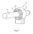
- Figure 9 is a perspective view showing a rod fixation system consisting of the implant member of Figure 7 , the spherical collet of Figure 6 , the tapered wedge of Figure 3 , and the cylindrical rod of Figure 2 ;
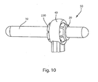
- Figure 10 is perspective view showing the side of the rod fixation system of Figure 9 ;
- Figure 11 is a cross-sectional view of the rod fixation system of Figure 9 in lock-out;
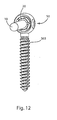
- Figure 12 is a perspective view of the taper lock feature used by a monolithic eyelet pedicle screw
- Figure 13 is a perspective view of an alternative embodiment of the taper lock feature utilizing the monolithic pedicle screw of Figure 12 and a taper integrally formed on the rod;
- Figure 14 is an exploded view of the assembly of Figure 13 ;
- Figure 15 is a perspective view of an alternative embodiment of the taper lock feature used by an open eyelet screw
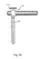
- Figure 16 is a lateral view of an alternative embodiment, not claimed, of the taper lock feature used by an open eyelet screw with a retainer;
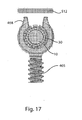
- Figure 17 is a wireframe view of the assembly of Figure 16 ;
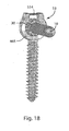
- Figure 18 is a perspective view of an alternative embodiment, not claimed, of the taper lock feature used by an open eyelet screw with a dogbone retainer;
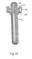
- Figure 19 is a top view of the assembly of Figure 18 ;
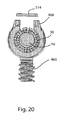
- Figure 20 is a wireframe view of the assembly of Figure 18 ;
- Figure 21 is a perspective view of the taper lock feature applied to a stackable implant member
- Figure 22 is a perspective view of the taper lock feature applied to a spinal hook
- Figure 23 is a perspective view of the taper lock feature applied to facet joint arthroplasty
- Figure 24 is a perspective view of the taper lock feature used in a spinal rod fixation system
- Figure 25 is a side view of the taper lock feature used with eyelet screws as a pedicle fixation device
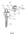
- Figure 26 is a perspective view of the taper lock feature used in a multi-level superior facet implant
- Figure 27 is an exploded view of the assembly of Figure 26 ;
- Figure 28 is a posterior view of the taper lock feature used in a single level facet replacement.
- the present invention relates to a device as claimed hereafter. Preferred embodiments of the invention are set forth in the dependent claims.
- the present invention advances the state of the art by providing systems that can be used to anchor orthopedic implants to bone in a manner that provides a high degree of implant adjustability, simplicity, and ease of use. Also disclosed, but not forming part of the invention, are methods that use such systems.
- the self-locking taper mechanism herein described is designed to secure a cylindrical rod within a receiving member or other device. In the case of spinal fixation, this taper lock would secure fixation between two or more vertebrae.
- the primary embodiment of the present invention concerns a system for securing a spinal fixation rod to a fixation member such as a pedicle screw or intermediate attachment to the pedicle.
- the present invention can be used in any orthopedic procedure, but may have particular utility in the field of facet joint replacement to alleviate back pain resulting from traumatic, inflammatory, metabolic, synovial, neoplastic and degenerative spinal disorders.
- elements of the implant beyond the rod fixation member can vary to be used for spinal fixation, facet arthroplasty, multi-level facet arthroplasty, combination of facet arthroplasty and spinal fixation, cross-linking between spinal implants, or other applications.
- polyaxial rotation is rotation that can occur about at least two axes that are not parallel to each other.
- Lock-out between two or more component parts refers to a state in which movement of any component part is prevented by frictional, compression, expansion, or other forces.
- a “taper-lock connector” refers to any locking mechanism that uses a taper to effect locking.
- Uniform radial expansion refers to radial expansion in which the radius increases substantially the same distance at each location on the circumference, that is, one portion does not increase significantly more or less.
- Figure 1 illustrates the main components needed for the preferred embodiment of the taper-lock fixation system herein described.
- the self-locking taper mechanism is shown to secure a cylindrical rod 10 within an implant member 40.
- Rod 10 is passed through tapered wedge 20, which in turn sits within spherical collet 30.
- the entire assembly of rod 10, wedge 20 and collet 30 is contained within implant member 40, which has a spherical inner surface, allowing the rod-taper lock assembly to have polyaxial motion prior to lock-out.
- the cone 14 of polyaxial motion which is allowed prior to lock-out is shown in Figure 1 along the axis 12 through the opening of the implant member 40..
- Rod 10 is designed to initially pass through wedge 20 freely allowing the position of rod 10 relative to the wedge 20 and collet 30 to be completely adjustable prior to lock-out. Additionally, the orientation of rod 10 can be adjusted in a polyaxial or conical manner due to the spherical articulation between collet 30 and implant 40. Once the desired position and orientation of rod 10 is determined, the system is locked out.
- cylindrical rod 10 is illustrated further in Figure 2 .
- cylindrical rod 10 may encompass any elongated member of varying length 15 and diameter 18.
- elongated members of other lengths, diameters and configurations may be used.
- the elongated member may be entirely straight, curved along a segment, bent, tapered, or otherwise configured.
- the elongated member may be a discrete element as depicted in Figure 2 , or may be joined to or monolithically formed with other components.
- Wedge 20 is illustrated further in Figures 3 and 4 .
- tapered wedge 20 describes any wedge piece comprised of cylindrical inner diameter 28 and tapered outer diameter 29. Inner diameter 28 is configured to receive cylindrical rod 10.
- the tapered wedge 20 shown in Figures 3 and 4 also contains at least one opening or slot 25 down one side, to allow for contraction of wedge 20. It is understood within the scope of the present invention that wedge 20 may have varying degrees of taper and/or varying lengths. It is also understood that the length, width, number of and/or orientation of slots 25 can be varied.
- the spherical collet 30 shown in Figure 1 and described above may include various embodiments.
- Figure 5 shows one embodiment of a spherical collet.
- Spherical collet 130 of Figure 5 consists of a spherical body 133, which has flat top 131 and bottom 139.
- a hollow, conical channel 135 runs through the center of collet 130 for receiving tapered wedge 20.
- Channel 135 may taper from top 131 to bottom 139, and the degree of the taper may be the same as the taper of the wedge piece 20.
- An outer convex wall 134 of collet 130 may be roughened to provide friction when locked-out, and the outer convex wall 134 includes a plurality of slots 138 to allow the sphere to expand and contract.
- the multiple slots 138 create between them multiple outer surface sections on the collet, allowing for more points of contact with the inner surface of the implant 40 when the taper-lock is assembled.
- the multiple slots additionally allow substantially uniform radial expansion and compression of the collet, since each section of the collet between the slots can expand or contract the same distance.
- the top surface of the sphere may be varied in its geometry.
- Collet 230 of Figure 6 is similar to collet 130 of Figure 5 .
- Collet 230 includes channel 235 through its center as well as slots 238 along an outer convex wall 234 to allow for expansion and contraction.
- collet 230 includes flange 237 on the top surface 231 of the collet.
- Flange 237 may be helpful in creating a surface for the application of force by instrumentation.
- Other embodiments may include a flange which is not curved but straight, or a rim which projects longitudinally from the top of the sphere but does not extend outward.
- a flange or rim portion on the collet may limit over-rotation or other undesired movement of the sphere during assembly of the taper-locking mechanism, so that the channel into which the wedge and rod are positioned is always visible and accessible.
- the implant portion of the spinal rod fixation system consists of implant member 40 containing a concave spherical inner surface 42, as shown in Figure 7 .
- the radius of inner surface 42 is equal to the outer radius of spherical collet 30, so that implant member 40 provides a housing which can easily receive collet 30.
- Inner surface 42 may be roughened to help generate the frictional forces necessary for the polyaxial lock-out.
- Outer surface 44 of the implant member is shown as circular in Figure 7 , but may conceivably consist of any other geometry.
- the portion of implant 40 shaped to receive the collet 30, wedge 20, and rod 10 may also be referred to as a housing. Elements of the implant member 40 beyond its use in rod fixation may be used for spinal fixation, facet arthroplasty, or other applications.
- Implant member 40 may also be mounted to screws, hooks, artificial joints, crossbar and cross members, or other applications.
- FIG. 8 shows assembly 50 which uses spherical collet 130
- Figures 9 and 10 depict assembly 50 with flanged spherical collet 230.
- Lock-out occurs by pressing tapered wedge 20 into the spherical collet along the longitudinal axis of rod 10, as shown in Figure 11 .
- Forces 1 and 2 are applied on wedge 20 and the opposite side of flanged spherical collet 230 to achieve insertion of tapered wedge 20.
- Forces 1 and 2 may be applied manually, or a separate tool (not shown) may be used to apply the forces.
- tapered wedge 20 is pressed into spherical collet 230, the contact forces between wedge 20 and spherical collet 230 cause tapered wedge 20 to compress around cylindrical rod 10. This compression force, shown by arrows 3, locks rod 10 in position along its length.
- Figures 12-20 show multiple embodiments of the taper lock rod fixation system. All systems incorporate the core concept of the present invention, using a tapered interface to increase contact force around spherical collet 30 as a lock-out mechanism to secure rod 10 and collet 30 within the implant member.
- Figure 12 is a perspective view of a monolithic member comprised of eyelet pedicle screw 365 and the taper lock feature 50 securing rod 10.
- Taper lock assembly 50 includes wedge 20 and spherical collet 30 contained within a housing 367 of eyelet pedicle screw 365.
- FIGs 13 and 14 show an alternative embodiment 51 of the taper lock feature.
- Taper lock 51 is shown to hold rod 11 within eyelet pedicle screw 365.
- Taper lock 51 does not include tapered wedge 20, however. Instead, rod 11 has a tapered section built into the rod.
- the tapered section 16 is integrally formed as part of rod 11, which fits in spherical collet 30 and housing 367 of eyelet screw 365. Similar to the tapered wedge 20 of taper lock assembly 50, tapered section 16 may have a degree of taper substantially equal to the degree of taper of the channel of the collet.
- the tapered section 16 engages with the channel of the collet 30, eventually causing the collet 30 to radially expand, and engage with the housing 367.
- the outer surface of the collet 30 and inner surface of the housing 367 may be roughened to provide increased friction.
- Figure 15 is a perspective view of an implant member comprised of open eyelet screw 465 and an alternative embodiment 52 of the taper lock feature with opening 405 on the top surface of implant member 465 to facilitate top loading of rod 10 and tapered wedge 20.
- a split collet 330 enables drop-in placement of the rod and wedge.
- FIG 16 and 17 depict another open eyelet screw 465 with alternative taper lock 53, not claimed, which does not require a tapered wedge 20.
- eyelet screw 465 includes retainer 512.
- retainer 512 is tapered as well as top flanges 468 of eyelet screw 465.
- Spherical collet 230 is placed inside concave housing 467, and rod 10 is inserted into the collet 230.
- Retainer 512 is pushed down over flanges 468 of eyelet screw 465, squeezing them together to engage and compress spherical collet 230 and grip rod 10. After assembly, flanges 468 are retained in the compressed position by the retainer 512.
- FIG. 18 shows taper lock 53 which is composed of rod 10, spherical collet 230, open eyelet screw 465, and dogbone retainer 514.
- dogbone retainer 514 and flanges 468 on eyelet screw 465 have tapered surfaces so that flanges 468 are pulled together as retainer 514 is inserted into flanges 468.
- Housing 467 is consequently closed around spherical collet 230, engaging and compressing spherical collet 30 and gripping rod 10.
- Figure 21 is a perspective view of taper lock feature 50 applied to join rod 610 to stackable implant member 640, to be used in conjunction with a screw, post, or similar member.
- Figure 22 is a perspective view of taper lock feature 50 applied to fix rod 710 in spinal hook 740.
- FIG 23 is a perspective view of the taper lock system of the present invention applied to facet joint arthroplasty.
- Implantable superior facet member 842 comprises a housing 844, a fastener port 846 and a superior articulation surface 848.
- the housing 844 is shaped to secure a taper lock assembly 50.
- the fastener port 846 is shaped to receive a pedicle screw or other fastener or anchor, to secure the superior facet member 842 to a vertebra.
- the superior articulation surface 848 is shaped to articulate with an inferior facet member or natural inferior facet.
- a taper lock assembly 50 secures the cephalad end of cylindrical rod 810 to the superior member 842 within the housing 844.
- an inferior facet member 852 is secured by a second taper lock assembly 50, or another polyaxial connection, to the caudal end of the rod 810.
- Inferior facet member 852 has an inferior articulation surface 854 which articulates with a second superior facet articulation surface 864 on a second superior facet member 862.
- Superior facet member 862 is similar to superior facet member 842 except that it does not have a housing for a taper lock connection.
- superior facet member 862 may be replaced with a superior facet member 842, which may connect, via a second taper lock connection, with a second rod and inferior facet member.
- Figure 24 is a perspective view of a spinal rod fixation system which utilizes the taper lock system of the present invention to provide rigid support between two vertebrae. Fixation to the bone is achieved through pedicle screws 965 shown.
- Taper lock assembly 50 may be used to secure spinal rod 910 to spinal implant members 940. Taper lock assembly 50 may also be used to secure pedicle screws 965 within spinal implant members 940. Using taper lock assemblies allows individualized positioning and orientation of the rod 910 relative to the two pedicle screws 965. A longer rod may be used with additional pedicle screws 965 and taper lock assemblies 50 to provide rigid support across additional vertebral levels.
- Fig 25 depicts a first eyelet screw 1065 with taper lock assembly 50 connected to a second eyelet screw 1065 with taper lock assembly 50 for pedicle-to-pedicle fixation.
- Figures 26 and 27 show multiple embodiments of the taper lock used on a multilevel facet implant with a crossbar.
- Figure 26 is a perspective view of the assembled implant, which includes a pedicle screw 1165, a superior member 1120, a linking rod 1140, an inferior member 1160 and a crossbar 1180.
- Three different taper locks are shown: taper lock 1190 locks superior member 1120 to the pedicle screw 1165, taper lock 1192 locks a split housing 1114 to the linking rod 1140, and taper lock 1196 locks the linking rod 1140 to the inferior member 1160.
- a polyaxial crosslink clamp 1199 links the linking rod 1140 to the crossbar 1180.
- FIG 27 is an exploded view of the assembly of Figure 26 .
- Taper lock 1190 comprises implantable pedicle screw 1165, wedge portion 1110, collet 130, and nut 1112. During assembly, wedge portion 1110 is slid onto implanted pedicle screw 1165. Spherical collet 130 is pre-assembled in an internal concave housing 1122 in the superior member 1120, and these are placed together over the wedge portion 1110. At this point, the superior member 1120 may be polyaxially rotated to attain its preferred orientation.
- a tool (not shown) is used to apply force to the collet 130 and the housing 1122, and the collet radially expands to engage the housing 1122 as it moves down the wedge portion 1110, and the orientation is locked.
- the wedge portion may compress around the pedicle screw 1165, locking the wedge portion 1110 to the pedicle screw, or it may not compress around the screw and remain free to slide up and down the screw.
- Nut 1112 is placed in the collet 130 and screwed to the end of the pedicle screw 1165.
- the linking rod 1140 is locked to the inferior member 1160 with a taper lock 1196.
- taper lock 1196 the positions of the spherical member (the collet in other embodiments) and the wedge are reversed from their positions in other embodiments.
- the inferior member 1160 includes an inferior articulation surface 1161, and a sphere 1162, which is sized to fit into a spherical housing 1164 within a slotted tapered wedge 1166. During pre-assembly, the sphere 1162 is fitted into the spherical housing 1164 and together they are fitted into a ring 1142 on the inferior end of the linking rod 1140.
- the orientation of the inferior member 1160, and thus the inferior articulation surface 1161, may be set by rotating the sphere 1162.
- a nut 1144 is placed over the end of the slotted tapered wedge 1166, and as the nut is tightened, the slotted tapered wedge 1166 tightens around the sphere 1162, locking the orientation of the inferior member 1160.
- Crossbar 1180 and collet 1182 are locked to the linking rod 1140 with the polyaxial crosslink clamp 1199.
- a split housing 1114 connects the linking rod 1140 with the pedicle screw assembly.
- Collet 130 is placed inside the split housing 114, and the housing is pinched and snapped into the top of the concave housing 1122 in the superior member 1120.
- a tapered rim 1116 on the flanges of the housing engages with a tapered rim 1126 on the housing 1122, and the split housing 1114 is snapped into place.
- the split housing 1114 may be rotatable, thus allowing rotation of the position of the inferior member 1160 and the crossbar 1180.
- Taper lock 1192 comprises the linking rod 1140, the split housing 1114, and collet 130, and a slotted tapered wedge 1130.
- the slotted tapered wedge 1130 is positioned within the channel of collet 130, and linking rod 1140 (with the inferior member 1160 and crossbar 1180 now attached) is inserted into the slotted tapered wedge 1130.
- a tool such as pliers or a similar tool, compression forces are applied to the opposite ends of the slotted wedge and the collet, in the same manner as illustrated in Figure 11 .
- the split housing 1114 is also locked in position relative to the housing 1122, because as the collet 130 expands and engages the split housing 1114, the split housing 1114 consequently expands and engages the housing 1122.
- Figure 28 shows a bilateral single level facet replacement 1200 using taper lock technology to fasten the inferior facet members to the pedicles.
- Left and right sides show two different embodiments of taper lock assembly 50 and attachment to pedicles 5 and 6.
- a taper lock assembly 50 is used to lock an inferior facet member 1220 directly to an eyelet pedicle screw 1205 which is implanted in the pedicle.
- a taper lock assembly 50 locks an inferior facet member 1222 to a first end of a linking member 1210.
- a polyaxial connection which may be a taper lock affixes a second end of the linking member 1210 to a pedicle screw 1215.
- the present invention includes variances of the system herein described.
- Alternative embodiments may include different geometries, intermediate parts, etc.
- Additional parts may include locking nuts or other fasteners to secure the position of the wedge, collet and rod. Changes in the geometry, especially on the ends of wedge 20 or collet 30, could be made to facilitate instrumentation or overall function.
- Applications of the present invention may include spinal fixation using screws or hooks or similar interfaces.
- the taper lock system may also be used by cross bars or cross linking systems to connect spinal implants and/or rods, as well as single- or multi-level facet joint replacement, or other iterations in which a rod or rod-like member is fixed to a second member.
- wedge or collet configuration features can vary, as can the type of implant retaining the taper-lock fixation system.
- the described embodiments are to be considered in all respects only as illustrative and not restrictive.
Landscapes
- Health & Medical Sciences (AREA)
- Orthopedic Medicine & Surgery (AREA)
- Life Sciences & Earth Sciences (AREA)
- Neurology (AREA)
- Surgery (AREA)
- Heart & Thoracic Surgery (AREA)
- Engineering & Computer Science (AREA)
- Biomedical Technology (AREA)
- Nuclear Medicine, Radiotherapy & Molecular Imaging (AREA)
- Medical Informatics (AREA)
- Molecular Biology (AREA)
- Animal Behavior & Ethology (AREA)
- General Health & Medical Sciences (AREA)
- Public Health (AREA)
- Veterinary Medicine (AREA)
- Surgical Instruments (AREA)
- Prostheses (AREA)
Description
- The present invention generally describes a mechanism by which a rod or rod-like device is secured within a second member via a taper-lock.
-
FR 2786088 -
US 2005/0119748 discloses cephalad and caudal vertebral facet joint prostheses. In these devices a pair of fixation elements are adapted to be secured within a vertebra in an orientation that best assures a secure and durable attachment to cortical and/or cancellous bone. Artificial facet joint surfaces are mounted on the fixation elements. The artificial facet joint structure is adapted for articulation with a complementary natural or artificial facet joint structure. -
US 2006/0217718 describes a crosslink for securing orthopaedic implants, such as facet joint replacement implants, together. The crosslink has a pair of implant coupling components, a pair of rod coupling components, a rod, and a pair of fasteners. Each facet joint implant may include a semicylindrical interface received in a resilient member of the corresponding implant coupling component to permit relative cephalad/caudal adjustment between the crosslink and the implants. The resilient members grip the semicylindrical interface of the implant to enable at least temporary attachment of the implant coupling components to the implants independently of the rod. Clocking features on the semicylindrical interfaces and on the interfacing areas of the implant coupling components and rod coupling components may limit assembly of the crosslink to discrete relative orientations and prevent play after assembly. The fasteners secure the rod coupling components to the rod at the desired positions along the rod. -
US 2005/0070899 describes an adjustable spinal fixation system composed of a collection of anchoring assemblies attached, via a variety of connectors, to spine-stabilizing rods. The anchoring assemblies include a linking member attached in a ball-and-socket fashion to a bone-engaging member that is adapted to engage a spinal bone of a patient. The linking member joins one of the included connectors to an associated bone-engaging member. The connectors are selectively attached to one of the stabilizing rods. The anchoring assemblies each include a support collar and a split retention ring that cooperate to allow adjustment of the bone-engaging member and corresponding connector during surgery. When surgery is complete, a linear engaging fastener cooperates with the support collar and split retention ring to maintain the relative position of the entire fixation system, preventing unwanted movement between the system components. -
US 2005/0192572 describes a pedicle screw assembly and method of assembly. The assembly comprises a longitudinal member; a bendable ball ring adapted to receive the longitudinal member; a poly stem comprising a bendable male bulbous end; and a connector comprising a pair of first apertures adapted to receive the poly stem; and a second aperture adapted to receive the ball ring and the longitudinal member, wherein the second aperture is transverse to the first aperture. The assembly further comprises a bone fixator component comprising a female socket adapted to receive the poly stem; and a blocker pin adapted to engage the poly stem and to secure the longitudinal member. - Various embodiments of the present invention will now be discussed with reference to the appended drawings. It is appreciated that these drawings, except in
figures 16-20 , depict only typical embodiments of the invention and are therefore not to be considered limiting of its scope. -
Figure 1 is a perspective view of a rod fixation system consisting of an implant member, a spherical collet, a tapered wedge, and a cylindrical rod; -
Figure 2 shows an example of a cylindrical rod; -
Figure 3 is a side view of a tapered wedge; -
Figure 4 is a top view of the tapered wedge ofFigure 3 ; -
Figure 5 is a perspective view of one embodiment of a spherical collet; -
Figure 6 is a perspective view of another embodiment of a spherical collet; -
Figure 7 is a perspective view of an implant member which may use a taper lock system for rod fixation; -
Figure 8 is a perspective view showing a rod fixation system consisting of the implant member ofFigure 7 , the spherical collet ofFigure 5 , the tapered wedge ofFigure 3 , and the cylindrical rod ofFigure 2 ; -
Figure 9 is a perspective view showing a rod fixation system consisting of the implant member ofFigure 7 , the spherical collet ofFigure 6 , the tapered wedge ofFigure 3 , and the cylindrical rod ofFigure 2 ; -
Figure 10 is perspective view showing the side of the rod fixation system ofFigure 9 ; -
Figure 11 is a cross-sectional view of the rod fixation system ofFigure 9 in lock-out; -
Figure 12 is a perspective view of the taper lock feature used by a monolithic eyelet pedicle screw; -
Figure 13 is a perspective view of an alternative embodiment of the taper lock feature utilizing the monolithic pedicle screw ofFigure 12 and a taper integrally formed on the rod; -
Figure 14 is an exploded view of the assembly ofFigure 13 ; -
Figure 15 is a perspective view of an alternative embodiment of the taper lock feature used by an open eyelet screw; -
Figure 16 is a lateral view of an alternative embodiment, not claimed, of the taper lock feature used by an open eyelet screw with a retainer; -
Figure 17 is a wireframe view of the assembly ofFigure 16 ; -
Figure 18 is a perspective view of an alternative embodiment, not claimed, of the taper lock feature used by an open eyelet screw with a dogbone retainer; -
Figure 19 is a top view of the assembly ofFigure 18 ; -
Figure 20 is a wireframe view of the assembly ofFigure 18 ; -
Figure 21 is a perspective view of the taper lock feature applied to a stackable implant member; -
Figure 22 is a perspective view of the taper lock feature applied to a spinal hook; -
Figure 23 is a perspective view of the taper lock feature applied to facet joint arthroplasty; -
Figure 24 is a perspective view of the taper lock feature used in a spinal rod fixation system; -
Figure 25 is a side view of the taper lock feature used with eyelet screws as a pedicle fixation device; -
Figure 26 is a perspective view of the taper lock feature used in a multi-level superior facet implant; -
Figure 27 is an exploded view of the assembly ofFigure 26 ; and -
Figure 28 is a posterior view of the taper lock feature used in a single level facet replacement. - The present invention relates to a device as claimed hereafter. Preferred embodiments of the invention are set forth in the dependent claims. The present invention advances the state of the art by providing systems that can be used to anchor orthopedic implants to bone in a manner that provides a high degree of implant adjustability, simplicity, and ease of use. Also disclosed, but not forming part of the invention, are methods that use such systems. The self-locking taper mechanism herein described is designed to secure a cylindrical rod within a receiving member or other device. In the case of spinal fixation, this taper lock would secure fixation between two or more vertebrae. The primary embodiment of the present invention concerns a system for securing a spinal fixation rod to a fixation member such as a pedicle screw or intermediate attachment to the pedicle. The present invention can be used in any orthopedic procedure, but may have particular utility in the field of facet joint replacement to alleviate back pain resulting from traumatic, inflammatory, metabolic, synovial, neoplastic and degenerative spinal disorders. However, it is understood within the scope of the invention that elements of the implant beyond the rod fixation member can vary to be used for spinal fixation, facet arthroplasty, multi-level facet arthroplasty, combination of facet arthroplasty and spinal fixation, cross-linking between spinal implants, or other applications.
- In this application, "polyaxial" rotation is rotation that can occur about at least two axes that are not parallel to each other. "Lock-out" between two or more component parts refers to a state in which movement of any component part is prevented by frictional, compression, expansion, or other forces. A "taper-lock connector" refers to any locking mechanism that uses a taper to effect locking. "Uniform radial expansion" refers to radial expansion in which the radius increases substantially the same distance at each location on the circumference, that is, one portion does not increase significantly more or less.
-
Figure 1 illustrates the main components needed for the preferred embodiment of the taper-lock fixation system herein described. The self-locking taper mechanism is shown to secure acylindrical rod 10 within animplant member 40.Rod 10 is passed through taperedwedge 20, which in turn sits withinspherical collet 30. The entire assembly ofrod 10,wedge 20 andcollet 30 is contained withinimplant member 40, which has a spherical inner surface, allowing the rod-taper lock assembly to have polyaxial motion prior to lock-out. Thecone 14 of polyaxial motion which is allowed prior to lock-out is shown inFigure 1 along theaxis 12 through the opening of theimplant member 40..Rod 10 is designed to initially pass throughwedge 20 freely allowing the position ofrod 10 relative to thewedge 20 andcollet 30 to be completely adjustable prior to lock-out. Additionally, the orientation ofrod 10 can be adjusted in a polyaxial or conical manner due to the spherical articulation betweencollet 30 andimplant 40. Once the desired position and orientation ofrod 10 is determined, the system is locked out. - The
cylindrical rod 10 is illustrated further inFigure 2 . In the present embodiment,cylindrical rod 10 may encompass any elongated member of varyinglength 15 anddiameter 18. However, it can be appreciated by one skilled in the art that elongated members of other lengths, diameters and configurations may be used. The elongated member may be entirely straight, curved along a segment, bent, tapered, or otherwise configured. In addition, the elongated member may be a discrete element as depicted inFigure 2 , or may be joined to or monolithically formed with other components. -
Wedge 20 is illustrated further inFigures 3 and4 . In the present invention, taperedwedge 20 describes any wedge piece comprised of cylindricalinner diameter 28 and taperedouter diameter 29.Inner diameter 28 is configured to receivecylindrical rod 10. The taperedwedge 20 shown inFigures 3 and4 also contains at least one opening orslot 25 down one side, to allow for contraction ofwedge 20. It is understood within the scope of the present invention thatwedge 20 may have varying degrees of taper and/or varying lengths. It is also understood that the length, width, number of and/or orientation ofslots 25 can be varied. - The
spherical collet 30 shown inFigure 1 and described above may include various embodiments.Figure 5 shows one embodiment of a spherical collet.Spherical collet 130 ofFigure 5 consists of aspherical body 133, which hasflat top 131 andbottom 139. A hollow,conical channel 135 runs through the center ofcollet 130 for receiving taperedwedge 20.Channel 135 may taper from top 131 tobottom 139, and the degree of the taper may be the same as the taper of thewedge piece 20. An outer convex wall 134 ofcollet 130 may be roughened to provide friction when locked-out, and the outer convex wall 134 includes a plurality ofslots 138 to allow the sphere to expand and contract. Themultiple slots 138 create between them multiple outer surface sections on the collet, allowing for more points of contact with the inner surface of theimplant 40 when the taper-lock is assembled. The multiple slots additionally allow substantially uniform radial expansion and compression of the collet, since each section of the collet between the slots can expand or contract the same distance. - In alternative embodiments of
spherical collet 30, the top surface of the sphere may be varied in its geometry. One such embodiment is shown inFigure 6 .Collet 230 ofFigure 6 is similar tocollet 130 ofFigure 5 .Collet 230 includeschannel 235 through its center as well asslots 238 along an outer convex wall 234 to allow for expansion and contraction. However,collet 230 includesflange 237 on thetop surface 231 of the collet.Flange 237 may be helpful in creating a surface for the application of force by instrumentation. Other embodiments may include a flange which is not curved but straight, or a rim which projects longitudinally from the top of the sphere but does not extend outward. A flange or rim portion on the collet may limit over-rotation or other undesired movement of the sphere during assembly of the taper-locking mechanism, so that the channel into which the wedge and rod are positioned is always visible and accessible. - The implant portion of the spinal rod fixation system consists of
implant member 40 containing a concave sphericalinner surface 42, as shown inFigure 7 . The radius ofinner surface 42 is equal to the outer radius ofspherical collet 30, so thatimplant member 40 provides a housing which can easily receivecollet 30.Inner surface 42 may be roughened to help generate the frictional forces necessary for the polyaxial lock-out.Outer surface 44 of the implant member is shown as circular inFigure 7 , but may conceivably consist of any other geometry. The portion ofimplant 40 shaped to receive thecollet 30,wedge 20, androd 10 may also be referred to as a housing. Elements of theimplant member 40 beyond its use in rod fixation may be used for spinal fixation, facet arthroplasty, or other applications.Implant member 40 may also be mounted to screws, hooks, artificial joints, crossbar and cross members, or other applications. - The
assembly 50 of the taper lock mechanism herein described is depicted inFigures 8 ,9 and10 .Cylindrical rod 10 passes through taperedwedge 20.Wedge portion 20 articulates concentrically within a spherical collet, which is positioned within the spherical inner radius housing ofimplant member 40.Figure 8 showsassembly 50 which usesspherical collet 130, whileFigures 9 and10 depictassembly 50 with flangedspherical collet 230. - Lock-out occurs by pressing tapered
wedge 20 into the spherical collet along the longitudinal axis ofrod 10, as shown inFigure 11 .Forces wedge 20 and the opposite side of flangedspherical collet 230 to achieve insertion of taperedwedge 20.Forces wedge 20 is pressed intospherical collet 230, the contact forces betweenwedge 20 andspherical collet 230 cause taperedwedge 20 to compress aroundcylindrical rod 10. This compression force, shown byarrows 3, locksrod 10 in position along its length. The insertion ofwedge 20 intocollet 30 also simultaneously expandsspherical collet 230, causing its outer surface to press againstinner surface 42 ofimplant 40. This expansion, denoted byarrows 4, locksspherical collet 230 and thereby wedge 20 androd 10 within theimplant 40, eliminating polyaxial motion and maintaining the desired orientation ofrod 10 relative to theimplant 40. Lock-out of a taper lock rod fixation system using a non-flanged spherical collet, such as the system depicted inFigure 8 includingcollet 130, is accomplished in the same manner. -
Figures 12-20 show multiple embodiments of the taper lock rod fixation system. All systems incorporate the core concept of the present invention, using a tapered interface to increase contact force aroundspherical collet 30 as a lock-out mechanism to securerod 10 andcollet 30 within the implant member.Figure 12 is a perspective view of a monolithic member comprised ofeyelet pedicle screw 365 and thetaper lock feature 50 securingrod 10.Taper lock assembly 50 includeswedge 20 andspherical collet 30 contained within ahousing 367 ofeyelet pedicle screw 365. -
Figures 13 and14 show analternative embodiment 51 of the taper lock feature. Taper lock 51 is shown to holdrod 11 withineyelet pedicle screw 365. Taper lock 51 does not include taperedwedge 20, however. Instead,rod 11 has a tapered section built into the rod. As seen inFigure 14 , the taperedsection 16 is integrally formed as part ofrod 11, which fits inspherical collet 30 andhousing 367 ofeyelet screw 365. Similar to the taperedwedge 20 oftaper lock assembly 50, taperedsection 16 may have a degree of taper substantially equal to the degree of taper of the channel of the collet. Whenrod 11 is pressed intocollet 30 and the housing of theeyelet screw 365, the taperedsection 16 engages with the channel of thecollet 30, eventually causing thecollet 30 to radially expand, and engage with thehousing 367. The outer surface of thecollet 30 and inner surface of thehousing 367 may be roughened to provide increased friction. -
Figure 15 is a perspective view of an implant member comprised ofopen eyelet screw 465 and analternative embodiment 52 of the taper lock feature with opening 405 on the top surface ofimplant member 465 to facilitate top loading ofrod 10 and taperedwedge 20. Asplit collet 330 enables drop-in placement of the rod and wedge. -
Figure 16 and17 depict anotheropen eyelet screw 465 withalternative taper lock 53, not claimed, which does not require a taperedwedge 20. Instead,eyelet screw 465 includesretainer 512. As shown inFigure 17 ,retainer 512 is tapered as well astop flanges 468 ofeyelet screw 465.Spherical collet 230 is placed inside concave housing 467, androd 10 is inserted into thecollet 230.Retainer 512 is pushed down overflanges 468 ofeyelet screw 465, squeezing them together to engage and compressspherical collet 230 andgrip rod 10. After assembly,flanges 468 are retained in the compressed position by theretainer 512. - An alternative embodiment not claimed, of
taper lock 53 is shown inFigures 18-20 .Figure 18 showstaper lock 53 which is composed ofrod 10,spherical collet 230,open eyelet screw 465, anddogbone retainer 514. As seen inFigures 19 and20 ,dogbone retainer 514 andflanges 468 oneyelet screw 465 have tapered surfaces so thatflanges 468 are pulled together asretainer 514 is inserted intoflanges 468. Housing 467 is consequently closed aroundspherical collet 230, engaging and compressingspherical collet 30 andgripping rod 10. - Applications of the present invention may include spinal fixation using screws or hooks or similar interfaces, as depicted in
Figures 21-28 .Figure 21 is a perspective view oftaper lock feature 50 applied to joinrod 610 tostackable implant member 640, to be used in conjunction with a screw, post, or similar member.Figure 22 is a perspective view oftaper lock feature 50 applied to fixrod 710 inspinal hook 740. -
Figure 23 is a perspective view of the taper lock system of the present invention applied to facet joint arthroplasty. Implantablesuperior facet member 842 comprises ahousing 844, afastener port 846 and asuperior articulation surface 848. Thehousing 844 is shaped to secure ataper lock assembly 50. Thefastener port 846 is shaped to receive a pedicle screw or other fastener or anchor, to secure thesuperior facet member 842 to a vertebra. Thesuperior articulation surface 848 is shaped to articulate with an inferior facet member or natural inferior facet. Ataper lock assembly 50 secures the cephalad end ofcylindrical rod 810 to thesuperior member 842 within thehousing 844. - Caudal to the
superior facet member 842, aninferior facet member 852 is secured by a secondtaper lock assembly 50, or another polyaxial connection, to the caudal end of therod 810.Inferior facet member 852 has aninferior articulation surface 854 which articulates with a second superiorfacet articulation surface 864 on a secondsuperior facet member 862.Superior facet member 862 is similar tosuperior facet member 842 except that it does not have a housing for a taper lock connection. For multi-level facet arthroplasty,superior facet member 862 may be replaced with asuperior facet member 842, which may connect, via a second taper lock connection, with a second rod and inferior facet member. -
Figure 24 is a perspective view of a spinal rod fixation system which utilizes the taper lock system of the present invention to provide rigid support between two vertebrae. Fixation to the bone is achieved throughpedicle screws 965 shown.Taper lock assembly 50 may be used to securespinal rod 910 tospinal implant members 940.Taper lock assembly 50 may also be used to secure pedicle screws 965 withinspinal implant members 940. Using taper lock assemblies allows individualized positioning and orientation of therod 910 relative to the two pedicle screws 965. A longer rod may be used withadditional pedicle screws 965 and taperlock assemblies 50 to provide rigid support across additional vertebral levels. -
Fig 25 depicts afirst eyelet screw 1065 withtaper lock assembly 50 connected to asecond eyelet screw 1065 withtaper lock assembly 50 for pedicle-to-pedicle fixation. -
Figures 26 and27 show multiple embodiments of the taper lock used on a multilevel facet implant with a crossbar.Figure 26 is a perspective view of the assembled implant, which includes apedicle screw 1165, asuperior member 1120, a linkingrod 1140, aninferior member 1160 and acrossbar 1180. Three different taper locks are shown:taper lock 1190 lockssuperior member 1120 to thepedicle screw 1165,taper lock 1192 locks a split housing 1114 to the linkingrod 1140, andtaper lock 1196 locks the linkingrod 1140 to theinferior member 1160. Apolyaxial crosslink clamp 1199 links the linkingrod 1140 to thecrossbar 1180. -
Figure 27 is an exploded view of the assembly ofFigure 26 .Taper lock 1190 comprisesimplantable pedicle screw 1165, wedge portion 1110,collet 130, andnut 1112. During assembly, wedge portion 1110 is slid onto implantedpedicle screw 1165.Spherical collet 130 is pre-assembled in an internalconcave housing 1122 in thesuperior member 1120, and these are placed together over the wedge portion 1110. At this point, thesuperior member 1120 may be polyaxially rotated to attain its preferred orientation. Once the proper orientation is attained, a tool (not shown) is used to apply force to thecollet 130 and thehousing 1122, and the collet radially expands to engage thehousing 1122 as it moves down the wedge portion 1110, and the orientation is locked. Simultaneously, the wedge portion may compress around thepedicle screw 1165, locking the wedge portion 1110 to the pedicle screw, or it may not compress around the screw and remain free to slide up and down the screw.Nut 1112 is placed in thecollet 130 and screwed to the end of thepedicle screw 1165. - The linking
rod 1140 is locked to theinferior member 1160 with ataper lock 1196. Intaper lock 1196, the positions of the spherical member (the collet in other embodiments) and the wedge are reversed from their positions in other embodiments. Theinferior member 1160 includes an inferior articulation surface 1161, and asphere 1162, which is sized to fit into aspherical housing 1164 within a slottedtapered wedge 1166. During pre-assembly, thesphere 1162 is fitted into thespherical housing 1164 and together they are fitted into a ring 1142 on the inferior end of the linkingrod 1140. The orientation of theinferior member 1160, and thus the inferior articulation surface 1161, may be set by rotating thesphere 1162. Anut 1144 is placed over the end of the slottedtapered wedge 1166, and as the nut is tightened, the slottedtapered wedge 1166 tightens around thesphere 1162, locking the orientation of theinferior member 1160.Crossbar 1180 andcollet 1182 are locked to the linkingrod 1140 with thepolyaxial crosslink clamp 1199. - A split housing 1114 connects the linking
rod 1140 with the pedicle screw assembly.Collet 130 is placed inside the split housing 114, and the housing is pinched and snapped into the top of theconcave housing 1122 in thesuperior member 1120. When the split housing 1114 is pushed down sufficiently, atapered rim 1116 on the flanges of the housing engages with atapered rim 1126 on thehousing 1122, and the split housing 1114 is snapped into place. Once snapped in and prior to lock-out, the split housing 1114 may be rotatable, thus allowing rotation of the position of theinferior member 1160 and thecrossbar 1180. -
Taper lock 1192 comprises the linkingrod 1140, the split housing 1114, andcollet 130, and a slottedtapered wedge 1130. The slottedtapered wedge 1130 is positioned within the channel ofcollet 130, and linking rod 1140 (with theinferior member 1160 andcrossbar 1180 now attached) is inserted into the slottedtapered wedge 1130. Using a tool such as pliers or a similar tool, compression forces are applied to the opposite ends of the slotted wedge and the collet, in the same manner as illustrated inFigure 11 . The interaction between the tapered channel in thecollet 130 and the slottedtapered wedge 1130 cause the wedge to compress around the linkingrod 1140 while thecollet 130 radially expands and engages the split housing 1114, thus locking the position and orientation of the linkingrod 1140. The split housing 1114 is also locked in position relative to thehousing 1122, because as thecollet 130 expands and engages the split housing 1114, the split housing 1114 consequently expands and engages thehousing 1122. -
Figure 28 shows a bilateral single level facet replacement 1200 using taper lock technology to fasten the inferior facet members to the pedicles. Left and right sides show two different embodiments oftaper lock assembly 50 and attachment topedicles pedicle 6, ataper lock assembly 50 is used to lock aninferior facet member 1220 directly to aneyelet pedicle screw 1205 which is implanted in the pedicle. Onpedicle 5, ataper lock assembly 50 locks aninferior facet member 1222 to a first end of a linkingmember 1210. A polyaxial connection which may be a taper lock affixes a second end of the linkingmember 1210 to apedicle screw 1215. - The present invention includes variances of the system herein described. Alternative embodiments may include different geometries, intermediate parts, etc. Additional parts may include locking nuts or other fasteners to secure the position of the wedge, collet and rod. Changes in the geometry, especially on the ends of
wedge 20 orcollet 30, could be made to facilitate instrumentation or overall function. Applications of the present invention may include spinal fixation using screws or hooks or similar interfaces. The taper lock system may also be used by cross bars or cross linking systems to connect spinal implants and/or rods, as well as single- or multi-level facet joint replacement, or other iterations in which a rod or rod-like member is fixed to a second member. - It is appreciated that various features of the above-described examples can be mixed and matched to form a variety of other alternatives. For example, wedge or collet configuration features can vary, as can the type of implant retaining the taper-lock fixation system. As such, the described embodiments are to be considered in all respects only as illustrative and not restrictive.
Claims (9)
- A system, comprising:an implant shaped to replace a first portion of a first natural facet joint, the implant comprising a first facet articular surface (848, 854, 1120, 1161);an elongated member (10, 810, 1140); anda locking connector coupled to the implant, the locking connector comprising:a housing (844, 1114); anda collet (30, 130, 230) receivable within the housing (844, 1114), the collet (30, 130, 230) comprising a channel shaped to receive the elongated member (10, 810, 1140); anda wedge portion (20, 1110, 1130) comprising a bore shaped to receive the elongated member, wherein the wedge portion comprises an outer tapered wall configured to induce expansion of the collet in response to urging of the wedge portion into the channel;wherein the collet (30, 130, 230) is radially expandable, wherein the locking connector is configured to lock an orientation and/or position of the housing (844, 1114) relative to the elongated member (10, 810, 1140) in response to radial expansion of the collet (30, 130, 230) to engage the housing (844, 1114),wherein the locking connector is configured to lock an orientation and/or a position of the implant relative to the elongated member (10, 810, 1140), such that lock-out occurs by pressing the wedge portion (20, 1110, 1130) into the collet (30, 130, 230) along a longitudinal axis of the elongated member (10, 810, 1140).
- The system of claim 1, further comprising a pedicle screw (1165) secured to a vertebra comprising the first portion of the first natural facet joint, wherein one of the elongated member (1140) and the housing (1114) is secured to the pedicle screw (1165).
- The system of claim 1, wherein the elongated member (1140) comprises a pedicle screw (1165) secured to a vertebra comprising the first portion of the first natural facet joint.
- The system of claim 1, wherein the channel comprises an inner tapered wall, and wherein the degree of taper of the outer tapered wall of the wedge portion (20, 1110, 1130) is substantially equal to the degree of taper of the inner tapered wall of the channel.
- The system of claim 1, wherein the collet (30, 130, 230) comprises a monolithic outer convex wall comprising a plurality of slots radially distributed about the outer convex wall to enable substantially uniform radial expansion of the collet (30, 130, 230).
- The system of claim 1, wherein the housing and the first facet articular surface are formed as a single piece with each other.
- The system of claim 1, wherein the housing (844, 1114) comprises an inner concave wall and the collet (30, 130, 230) comprises an outer convex wall, wherein at least one of the inner concave wall and the outer convex wall comprises a roughened surface.
- The system of claim 1, further comprising:a second implant configured to replace a second portion of the first natural facet joint, the second implant comprising a second facet articular surface, wherein the second facet articular surface is configured to articulate with the first facet articular surface.
- The system of claim 8, further comprising:a third implant configured to replace a first portion of a second natural facet joint; anda fourth implant configured to replace a second portion of the second natural facet joint;wherein the second natural facet joint is either one motion segment caudal or one motion segment cephalad to the first natural motion segment.
Applications Claiming Priority (22)
| Application Number | Priority Date | Filing Date | Title |
|---|---|---|---|
| US88423307P | 2007-01-10 | 2007-01-10 | |
| US91232307P | 2007-04-17 | 2007-04-17 | |
| US95003107P | 2007-07-16 | 2007-07-16 | |
| US95003807P | 2007-07-16 | 2007-07-16 | |
| US95001207P | 2007-07-16 | 2007-07-16 | |
| US95002107P | 2007-07-16 | 2007-07-16 | |
| US95750507P | 2007-08-23 | 2007-08-23 | |
| US96832407P | 2007-08-28 | 2007-08-28 | |
| US96892507P | 2007-08-30 | 2007-08-30 | |
| US97573107P | 2007-09-27 | 2007-09-27 | |
| US98442807P | 2007-11-01 | 2007-11-01 | |
| US98459407P | 2007-11-01 | 2007-11-01 | |
| US98443407P | 2007-11-01 | 2007-11-01 | |
| US98481407P | 2007-11-02 | 2007-11-02 | |
| US98498307P | 2007-11-02 | 2007-11-02 | |
| US98479807P | 2007-11-02 | 2007-11-02 | |
| US1434407P | 2007-12-17 | 2007-12-17 | |
| US1587607P | 2007-12-21 | 2007-12-21 | |
| US1588607P | 2007-12-21 | 2007-12-21 | |
| US1586607P | 2007-12-21 | 2007-12-21 | |
| US1584007P | 2007-12-21 | 2007-12-21 | |
| PCT/US2008/050739 WO2008086467A2 (en) | 2007-01-10 | 2008-01-10 | Taper-locking fixation system |
Publications (3)
| Publication Number | Publication Date |
|---|---|
| EP2114273A2 EP2114273A2 (en) | 2009-11-11 |
| EP2114273A4 EP2114273A4 (en) | 2012-07-25 |
| EP2114273B1 true EP2114273B1 (en) | 2013-11-06 |
Family
ID=39609370
Family Applications (1)
| Application Number | Title | Priority Date | Filing Date |
|---|---|---|---|
| EP08705833.5A Not-in-force EP2114273B1 (en) | 2007-01-10 | 2008-01-10 | Taper-locking fixation system |
Country Status (6)
| Country | Link |
|---|---|
| US (1) | US8900273B2 (en) |
| EP (1) | EP2114273B1 (en) |
| JP (1) | JP2010515543A (en) |
| AU (1) | AU2008204784A1 (en) |
| CA (1) | CA2675037A1 (en) |
| WO (1) | WO2008086467A2 (en) |
Families Citing this family (49)
| Publication number | Priority date | Publication date | Assignee | Title |
|---|---|---|---|---|
| US8926700B2 (en) | 2003-12-10 | 2015-01-06 | Gmedelware 2 LLC | Spinal facet joint implant |
| US8333789B2 (en) | 2007-01-10 | 2012-12-18 | Gmedelaware 2 Llc | Facet joint replacement |
| US8562649B2 (en) | 2004-02-17 | 2013-10-22 | Gmedelaware 2 Llc | System and method for multiple level facet joint arthroplasty and fusion |
| US9492203B2 (en) * | 2004-02-17 | 2016-11-15 | Globus Medical, Inc. | Facet joint replacement instruments and methods |
| US7588578B2 (en) | 2004-06-02 | 2009-09-15 | Facet Solutions, Inc | Surgical measurement systems and methods |
| US8114158B2 (en) | 2004-08-03 | 2012-02-14 | Kspine, Inc. | Facet device and method |
| AU2007238129A1 (en) | 2006-04-11 | 2007-10-25 | Synthes Gmbh | Minimally invasive fixation system |
| US9867640B2 (en) * | 2006-12-07 | 2018-01-16 | Nexus Spine, LLC | Press-on pedicle screw assembly |
| CA2689965A1 (en) | 2007-06-06 | 2008-12-18 | Kspine, Inc. | Medical device and method to correct deformity |
| BRPI0814609A2 (en) * | 2007-07-19 | 2015-01-27 | Synthes Gmbh | CLAMP TO FIX A BONE ANCHOR TO A ROD, AND A HOLDER TO MOUNT ON A VERTEB. |
| US20170143377A9 (en) * | 2011-04-25 | 2017-05-25 | Nexus Spine, L.L.C. | Surgical construct coupling system |
| US8864798B2 (en) * | 2008-01-18 | 2014-10-21 | Globus Medical, Inc. | Transverse connector |
| US8328806B2 (en) * | 2008-06-24 | 2012-12-11 | Extremity Medical, Llc | Fixation system, an intramedullary fixation assembly and method of use |
| US8313487B2 (en) * | 2008-06-24 | 2012-11-20 | Extremity Medical Llc | Fixation system, an intramedullary fixation assembly and method of use |
| US8828058B2 (en) | 2008-11-11 | 2014-09-09 | Kspine, Inc. | Growth directed vertebral fixation system with distractible connector(s) and apical control |
| EP2408389B1 (en) * | 2009-02-23 | 2021-04-14 | Crocker Spinal, L.L.C. | Press-on link for surgical screws |
| US20100249846A1 (en) * | 2009-03-25 | 2010-09-30 | Simonson Peter M | Variable height, multi-axial bone screw assembly |
| AU2015230721B2 (en) * | 2009-03-26 | 2017-11-16 | K2M, Inc. | Semi - constrained anchoring system for correcting a spinal deformity |
| US8357182B2 (en) * | 2009-03-26 | 2013-01-22 | Kspine, Inc. | Alignment system with longitudinal support features |
| WO2010135537A2 (en) | 2009-05-20 | 2010-11-25 | Synthes Usa, Llc | Patient-mounted retraction |
| US9168071B2 (en) | 2009-09-15 | 2015-10-27 | K2M, Inc. | Growth modulation system |
| US8535318B2 (en) | 2010-04-23 | 2013-09-17 | DePuy Synthes Products, LLC | Minimally invasive instrument set, devices and related methods |
| EP2397088A1 (en) * | 2010-06-18 | 2011-12-21 | Abasan S.r.l. | Device for producing a struction which can be implanted in at least one part of the spinal column of a subject suffering from scoliosis and/or from another vertebral pathology in order to stabilise and/or correct this pathology |
| EP2460482A1 (en) * | 2010-12-03 | 2012-06-06 | Zimmer Spine | Rod holding device |
| US9247964B1 (en) | 2011-03-01 | 2016-02-02 | Nuasive, Inc. | Spinal Cross-connector |
| US9387013B1 (en) * | 2011-03-01 | 2016-07-12 | Nuvasive, Inc. | Posterior cervical fixation system |
| EP2517660B1 (en) * | 2011-04-25 | 2018-03-07 | Nexus Spine, L.L.C. | Coupling system to connect two or more surgical screws |
| JP6072012B2 (en) | 2011-05-27 | 2017-02-01 | シンセス・ゲーエムベーハーSynthes GmbH | Minimally invasive spinal fixation system including vertebra alignment features |
| AU2012261983B2 (en) | 2011-06-03 | 2015-10-08 | K2M, Inc. | Spinal correction system actuators |
| US9451987B2 (en) | 2011-11-16 | 2016-09-27 | K2M, Inc. | System and method for spinal correction |
| US9468469B2 (en) | 2011-11-16 | 2016-10-18 | K2M, Inc. | Transverse coupler adjuster spinal correction systems and methods |
| US8920472B2 (en) | 2011-11-16 | 2014-12-30 | Kspine, Inc. | Spinal correction and secondary stabilization |
| WO2014172632A2 (en) | 2011-11-16 | 2014-10-23 | Kspine, Inc. | Spinal correction and secondary stabilization |
| US9468468B2 (en) | 2011-11-16 | 2016-10-18 | K2M, Inc. | Transverse connector for spinal stabilization system |
| ES2671883T3 (en) * | 2012-06-21 | 2018-06-11 | Aesculap Ag | Low Profile Bone Stabilization Systems |
| US20140074169A1 (en) * | 2012-09-13 | 2014-03-13 | Warsaw Orthopedic, Inc. | Spinal correction system and method |
| US9427272B2 (en) * | 2013-03-14 | 2016-08-30 | Kyphon SÀRL | Device for performing a surgical procedure and method |
| US9370380B2 (en) | 2013-03-15 | 2016-06-21 | Dne, Llc | External bone fixation system |
| US10258378B2 (en) * | 2013-03-15 | 2019-04-16 | Dne, Llc | External bone fixation system |
| US9517091B2 (en) | 2013-03-15 | 2016-12-13 | Warsaw Orthopediac, Inc. | Locking mechanism |
| US9468471B2 (en) | 2013-09-17 | 2016-10-18 | K2M, Inc. | Transverse coupler adjuster spinal correction systems and methods |
| US9044273B2 (en) * | 2013-10-07 | 2015-06-02 | Intelligent Implant Systems, Llc | Polyaxial plate rod system and surgical procedure |
| DE102015010741A1 (en) | 2015-03-19 | 2016-09-22 | Ngmedical Gmbh | Polyaxial pedicle screw with spherical segment-shaped head |
| US9757165B2 (en) | 2015-10-23 | 2017-09-12 | Warsaw Orthopedic, Inc. | Spinal implant system and method |
| WO2017143110A1 (en) * | 2016-02-16 | 2017-08-24 | Nexus Spine, LLC | Revision system for spinal implants |
| US11291476B2 (en) | 2016-06-10 | 2022-04-05 | Dne, Llc | External bone fixation system |
| USD809041S1 (en) * | 2016-09-15 | 2018-01-30 | Globus Medical, Inc. | Surgical robot end effector |
| US11191582B2 (en) * | 2018-05-09 | 2021-12-07 | Warsaw Orthopedic, Inc. | Bone screw and method of manufacture |
| US11534207B2 (en) | 2019-02-11 | 2022-12-27 | Next Orthosurgical, Inc. | Corrective angle pedicle screw technology |
Family Cites Families (338)
| Publication number | Priority date | Publication date | Assignee | Title |
|---|---|---|---|---|
| US2677369A (en) | 1952-03-26 | 1954-05-04 | Fred L Knowles | Apparatus for treatment of the spinal column |
| US3247000A (en) * | 1961-10-16 | 1966-04-19 | Carborundum Co | Refractory bodies and method of making same |
| US3298372A (en) * | 1963-12-17 | 1967-01-17 | Feinberg Maurice | Surgical hydrocephalus shunt sleeve for placement in a vertebra |
| US3426364A (en) * | 1966-08-25 | 1969-02-11 | Colorado State Univ Research F | Prosthetic appliance for replacing one or more natural vertebrae |
| US3486505A (en) | 1967-05-22 | 1969-12-30 | Gordon M Morrison | Orthopedic surgical instrument |
| US3508954A (en) * | 1967-10-05 | 1970-04-28 | Texaco Inc | Silicon carbide structures |
| US3534989A (en) * | 1968-05-29 | 1970-10-20 | Joslyn Mfg & Supply Co | End fitting |
| US3648691A (en) * | 1970-02-24 | 1972-03-14 | Univ Colorado State Res Found | Method of applying vertebral appliance |
| SE391122B (en) * | 1971-01-25 | 1977-02-07 | Cutter Lab | PROTESTS IN THE FORM OF A SPINE BONIC DISC AND PROCEDURES FOR MANUFACTURE THEREOF |
| US3857642A (en) | 1973-02-26 | 1974-12-31 | Ingersoll Rand Co | Flexible or universal coupling means |
| US3875595A (en) * | 1974-04-15 | 1975-04-08 | Edward C Froning | Intervertebral disc prosthesis and instruments for locating same |
| US4003376A (en) * | 1975-08-25 | 1977-01-18 | Bio-Dynamics, Inc. | Apparatus for straightening the spinal column |
| DE2655353A1 (en) | 1976-12-07 | 1978-06-08 | Lemfoerder Metallwaren Ag | ELASTIC CONNECTION OF AN AXIAL JOINT WITH THE CONNECTING ROD OF A MOTOR VEHICLE STEERING SYSTEM |
| US4289123A (en) | 1980-03-31 | 1981-09-15 | Dunn Harold K | Orthopedic appliance |
| US4369769A (en) * | 1980-06-13 | 1983-01-25 | Edwards Charles C | Spinal fixation device and method |
| CA1146301A (en) | 1980-06-13 | 1983-05-17 | J. David Kuntz | Intervertebral disc prosthesis |
| US4501269A (en) * | 1981-12-11 | 1985-02-26 | Washington State University Research Foundation, Inc. | Process for fusing bone joints |
| US4479491A (en) | 1982-07-26 | 1984-10-30 | Martin Felix M | Intervertebral stabilization implant |
| US4483334A (en) | 1983-04-11 | 1984-11-20 | Murray William M | External fixation device |
| FR2545350B1 (en) * | 1983-05-04 | 1985-08-23 | Cotrel Yves | DEVICE FOR SHRINKAGE OF THE RACHIS |
| US4554914A (en) | 1983-10-04 | 1985-11-26 | Kapp John P | Prosthetic vertebral body |
| US4611581A (en) | 1983-12-16 | 1986-09-16 | Acromed Corporation | Apparatus for straightening spinal columns |
| US4696290A (en) | 1983-12-16 | 1987-09-29 | Acromed Corporation | Apparatus for straightening spinal columns |
| US4604995A (en) | 1984-03-30 | 1986-08-12 | Stephens David C | Spinal stabilizer |
| FR2575059B1 (en) * | 1984-12-21 | 1988-11-10 | Daher Youssef | SHORING DEVICE FOR USE IN A VERTEBRAL PROSTHESIS |
| US4599086A (en) | 1985-06-07 | 1986-07-08 | Doty James R | Spine stabilization device and method |
| US4743260A (en) * | 1985-06-10 | 1988-05-10 | Burton Charles V | Method for a flexible stabilization system for a vertebral column |
| US4653481A (en) * | 1985-07-24 | 1987-03-31 | Howland Robert S | Advanced spine fixation system and method |
| SE458417B (en) | 1985-08-15 | 1989-04-03 | Sven Olerud | FIXING INSTRUMENTS PROVIDED FOR USE IN SPINE OPERATIONS |
| DE3614101C1 (en) | 1986-04-25 | 1987-10-22 | Juergen Prof Dr Med Harms | Pedicle screw |
| DE3620549A1 (en) | 1986-06-19 | 1987-12-23 | S & G Implants Gmbh | IMPLANT FOR FIXING NEXT SPINE BONES OF THE SPINE |
| AT387711B (en) * | 1986-07-15 | 1989-03-10 | David Thomas | BONE FIXATION PLATE |
| GB8620937D0 (en) | 1986-08-29 | 1986-10-08 | Shepperd J A N | Spinal implant |
| US4805602A (en) * | 1986-11-03 | 1989-02-21 | Danninger Medical Technology | Transpedicular screw and rod system |
| CA1283501C (en) | 1987-02-12 | 1991-04-30 | Thomas P. Hedman | Artificial spinal disc |
| US4790303A (en) | 1987-03-11 | 1988-12-13 | Acromed Corporation | Apparatus and method for securing bone graft |
| SU1468543A1 (en) | 1987-04-09 | 1989-03-30 | Харьковский Научно-Исследовательский Институт Ортопедии И Травматологии Им.Проф.М.И.Ситенко | Method of treatment of patients having arthrosis of arc-process vertebrae of the spine |
| US4863477A (en) | 1987-05-12 | 1989-09-05 | Monson Gary L | Synthetic intervertebral disc prosthesis |
| CH672588A5 (en) | 1987-07-09 | 1989-12-15 | Sulzer Ag | |
| US4772287A (en) * | 1987-08-20 | 1988-09-20 | Cedar Surgical, Inc. | Prosthetic disc and method of implanting |
| SU1517953A1 (en) | 1987-11-16 | 1989-10-30 | Запорожский Областной Отдел Здравоохранения | Apparatus for perosseous osteosynthesis |
| FR2623085B1 (en) * | 1987-11-16 | 1992-08-14 | Breard Francis | SURGICAL IMPLANT TO LIMIT THE RELATIVE MOVEMENT OF VERTEBRES |
| US5147404A (en) | 1987-12-07 | 1992-09-15 | Downey Ernest L | Vertebra prosthesis |
| FR2625097B1 (en) | 1987-12-23 | 1990-05-18 | Cote Sarl | INTER-SPINOUS PROSTHESIS COMPOSED OF SEMI-ELASTIC MATERIAL COMPRISING A TRANSFILING EYE AT ITS END AND INTER-SPINOUS PADS |
| US4911718A (en) * | 1988-06-10 | 1990-03-27 | University Of Medicine & Dentistry Of N.J. | Functional and biocompatible intervertebral disc spacer |
| CN1128944A (en) | 1988-06-13 | 1996-08-14 | 卡林技术公司 | Apparatus and method of inserting spinal implants |
| US5772661A (en) | 1988-06-13 | 1998-06-30 | Michelson; Gary Karlin | Methods and instrumentation for the surgical correction of human thoracic and lumbar spinal disease from the antero-lateral aspect of the spine |
| CA1333209C (en) | 1988-06-28 | 1994-11-29 | Gary Karlin Michelson | Artificial spinal fusion implants |
| DE3823737A1 (en) * | 1988-07-13 | 1990-01-18 | Lutz Biedermann | CORRECTION AND HOLDING DEVICE, ESPECIALLY FOR THE SPINE |
| US4892545A (en) * | 1988-07-14 | 1990-01-09 | Ohio Medical Instrument Company, Inc. | Vertebral lock |
| US5545229A (en) | 1988-08-18 | 1996-08-13 | University Of Medicine And Dentistry Of Nj | Functional and biocompatible intervertebral disc spacer containing elastomeric material of varying hardness |
| GB8825909D0 (en) | 1988-11-04 | 1988-12-07 | Showell A W Sugicraft Ltd | Pedicle engaging means |
| USRE36221E (en) | 1989-02-03 | 1999-06-01 | Breard; Francis Henri | Flexible inter-vertebral stabilizer as well as process and apparatus for determining or verifying its tension before installation on the spinal column |
| FR2642645B1 (en) * | 1989-02-03 | 1992-08-14 | Breard Francis | FLEXIBLE INTERVERTEBRAL STABILIZER AND METHOD AND APPARATUS FOR CONTROLLING ITS VOLTAGE BEFORE PLACEMENT ON THE RACHIS |
| CA1318469C (en) | 1989-02-15 | 1993-06-01 | Acromed Corporation | Artificial disc |
| SE8901315L (en) | 1989-04-11 | 1990-10-12 | Bjoern Albrektsson | Joint prosthesis |
| US5062845A (en) | 1989-05-10 | 1991-11-05 | Spine-Tech, Inc. | Method of making an intervertebral reamer |
| US5458638A (en) * | 1989-07-06 | 1995-10-17 | Spine-Tech, Inc. | Non-threaded spinal implant |
| CH678803A5 (en) | 1989-07-12 | 1991-11-15 | Sulzer Ag | |
| DE8912648U1 (en) * | 1989-10-23 | 1990-11-22 | Mecron Medizinische Produkte Gmbh, 1000 Berlin, De | |
| JPH066810Y2 (en) | 1989-11-29 | 1994-02-23 | 旭光学工業株式会社 | Vertebral body fixation plate |
| US5236460A (en) | 1990-02-12 | 1993-08-17 | Midas Rex Pneumatic Tools, Inc. | Vertebral body prosthesis |
| DE59100448D1 (en) | 1990-04-20 | 1993-11-11 | Sulzer Ag | Implant, in particular intervertebral prosthesis. |
| US5129900B1 (en) | 1990-07-24 | 1998-12-29 | Acromed Corp | Spinal column retaining method and apparatus |
| US5092893A (en) * | 1990-09-04 | 1992-03-03 | Smith Thomas E | Human orthopedic vertebra implant |
| FR2666981B1 (en) * | 1990-09-21 | 1993-06-25 | Commarmond Jacques | SYNTHETIC LIGAMENT VERTEBRAL. |
| US5127912A (en) | 1990-10-05 | 1992-07-07 | R. Charles Ray | Sacral implant system |
| ES2076467T3 (en) | 1990-10-31 | 1995-11-01 | El Gendler | FLEXIBLE MEMBRANES PRODUCED WITH ORGANIC BONE MATTER FOR THE REPAIR AND RECONSTRUCTION OF PARTS OF THE SKELETON. |
| US5192326A (en) * | 1990-12-21 | 1993-03-09 | Pfizer Hospital Products Group, Inc. | Hydrogel bead intervertebral disc nucleus |
| US5047055A (en) | 1990-12-21 | 1991-09-10 | Pfizer Hospital Products Group, Inc. | Hydrogel intervertebral disc nucleus |
| FR2672202B1 (en) * | 1991-02-05 | 1993-07-30 | Safir | BONE SURGICAL IMPLANT, ESPECIALLY FOR INTERVERTEBRAL STABILIZER. |
| JP3007903B2 (en) | 1991-03-29 | 2000-02-14 | 京セラ株式会社 | Artificial disc |
| FR2676911B1 (en) | 1991-05-30 | 1998-03-06 | Psi Ste Civile Particuliere | INTERVERTEBRAL STABILIZATION DEVICE WITH SHOCK ABSORBERS. |
| US5318567A (en) | 1991-07-02 | 1994-06-07 | Olivier Vichard | Screw-on plate for treatment of fractures of the odontoid apophysis |
| US5603713A (en) * | 1991-09-24 | 1997-02-18 | Aust; Gilbert M. | Anterior lumbar/cervical bicortical compression plate |
| US5313962A (en) | 1991-10-18 | 1994-05-24 | Obenchain Theodore G | Method of performing laparoscopic lumbar discectomy |
| US5263953A (en) | 1991-12-31 | 1993-11-23 | Spine-Tech, Inc. | Apparatus and system for fusing bone joints |
| US5258031A (en) | 1992-01-06 | 1993-11-02 | Danek Medical | Intervertebral disk arthroplasty |
| US5534031A (en) | 1992-01-28 | 1996-07-09 | Asahi Kogaku Kogyo Kabushiki Kaisha | Prosthesis for spanning a space formed upon removal of an intervertebral disk |
| US5261910A (en) | 1992-02-19 | 1993-11-16 | Acromed Corporation | Apparatus for maintaining spinal elements in a desired spatial relationship |
| DE4208116C2 (en) * | 1992-03-13 | 1995-08-03 | Link Waldemar Gmbh Co | Intervertebral disc prosthesis |
| DE4208115A1 (en) | 1992-03-13 | 1993-09-16 | Link Waldemar Gmbh Co | DISC ENDOPROTHESIS |
| US5171279A (en) | 1992-03-17 | 1992-12-15 | Danek Medical | Method for subcutaneous suprafascial pedicular internal fixation |
| NL9200612A (en) * | 1992-04-01 | 1993-11-01 | Acromed Bv | Device for correcting the shape and / or fixing the vertebral column of man. |
| FR2689750B1 (en) * | 1992-04-10 | 1997-01-31 | Eurosurgical | BONE ANCHORING ELEMENT AND SPINAL OSTEOSYNTHESIS DEVICE INCORPORATING SUCH ELEMENTS. |
| ATE141149T1 (en) | 1992-04-21 | 1996-08-15 | Sulzer Medizinaltechnik Ag | ARTIFICIAL DISC BODY |
| US5306309A (en) * | 1992-05-04 | 1994-04-26 | Calcitek, Inc. | Spinal disk implant and implantation kit |
| US5304178A (en) * | 1992-05-29 | 1994-04-19 | Acromed Corporation | Sublaminar wire |
| JP3308271B2 (en) * | 1992-06-25 | 2002-07-29 | ジンテーズ アクチエンゲゼルシャフト,クール | Osteosynthesis fixation device |
| FR2692952B1 (en) | 1992-06-25 | 1996-04-05 | Psi | IMPROVED SHOCK ABSORBER WITH MOVEMENT LIMIT. |
| FR2693364B1 (en) * | 1992-07-07 | 1995-06-30 | Erpios Snc | INTERVERTEBRAL PROSTHESIS FOR STABILIZING ROTATORY AND FLEXIBLE-EXTENSION CONSTRAINTS. |
| GB9217578D0 (en) | 1992-08-19 | 1992-09-30 | Surgicarft Ltd | Surgical implants,etc |
| US5246458A (en) | 1992-10-07 | 1993-09-21 | Graham Donald V | Artificial disk |
| US5562735A (en) | 1992-11-09 | 1996-10-08 | Hospital For Joint Diseases | Spinal stabilization system and improved method |
| US5611354A (en) * | 1992-11-12 | 1997-03-18 | Alleyne; Neville | Cardiac protection device |
| EP1149560A3 (en) | 1992-11-12 | 2002-03-06 | ALLEYNE, Neville | Spinal protection device |
| US5814046A (en) | 1992-11-13 | 1998-09-29 | Sofamor S.N.C. | Pedicular screw and posterior spinal instrumentation |
| US5306275A (en) * | 1992-12-31 | 1994-04-26 | Bryan Donald W | Lumbar spine fixation apparatus and method |
| US5456722A (en) | 1993-01-06 | 1995-10-10 | Smith & Nephew Richards Inc. | Load bearing polymeric cable |
| US5496318A (en) * | 1993-01-08 | 1996-03-05 | Advanced Spine Fixation Systems, Inc. | Interspinous segmental spine fixation device |
| US5676701A (en) | 1993-01-14 | 1997-10-14 | Smith & Nephew, Inc. | Low wear artificial spinal disc |
| ES2161725T3 (en) | 1993-02-09 | 2001-12-16 | Depuy Acromed Inc | INTERVERTEBRAL DISC. |
| FR2701650B1 (en) * | 1993-02-17 | 1995-05-24 | Psi | Double shock absorber for intervertebral stabilization. |
| US5549607A (en) | 1993-02-19 | 1996-08-27 | Alphatec Manufacturing, Inc, | Apparatus for spinal fixation system |
| US5439464A (en) | 1993-03-09 | 1995-08-08 | Shapiro Partners Limited | Method and instruments for performing arthroscopic spinal surgery |
| US5470333A (en) | 1993-03-11 | 1995-11-28 | Danek Medical, Inc. | System for stabilizing the cervical and the lumbar region of the spine |
| US5531745A (en) | 1993-03-11 | 1996-07-02 | Danek Medical, Inc. | System for stabilizing the spine and reducing spondylolisthesis |
| JP2559098B2 (en) | 1993-03-15 | 1996-11-27 | ジンテーズ アクチエンゲゼルシャフト,クール | Hook with screw for spinal deformity treatment |
| DE4308750A1 (en) | 1993-03-19 | 1994-09-22 | Esselte Meto Int Gmbh | Article security element |
| US5415661A (en) | 1993-03-24 | 1995-05-16 | University Of Miami | Implantable spinal assist device |
| US5534028A (en) | 1993-04-20 | 1996-07-09 | Howmedica, Inc. | Hydrogel intervertebral disc nucleus with diminished lateral bulging |
| FR2707480B1 (en) | 1993-06-28 | 1995-10-20 | Bisserie Michel | Intervertebral disc prosthesis. |
| US5360430A (en) | 1993-07-29 | 1994-11-01 | Lin Chih I | Intervertebral locking device |
| US5437669A (en) | 1993-08-12 | 1995-08-01 | Amei Technologies Inc. | Spinal fixation systems with bifurcated connectors |
| FR2722393B1 (en) | 1993-08-27 | 1996-08-23 | Martin Jean Raymond | ANCILLARY MATERIAL FOR CORRECTING A VERTEBRAL DEFORMATION |
| FR2709247B1 (en) | 1993-08-27 | 1995-09-29 | Martin Jean Raymond | Device for anchoring spinal instrumentation on a vertebra. |
| FR2709246B1 (en) | 1993-08-27 | 1995-09-29 | Martin Jean Raymond | Dynamic implanted spinal orthosis. |
| FR2709248B1 (en) | 1993-08-27 | 1995-09-29 | Martin Jean Raymond | Ancillary equipment for placing a spinal instrumentation. |
| US5458641A (en) | 1993-09-08 | 1995-10-17 | Ramirez Jimenez; Juan J. | Vertebral body prosthesis |
| CN1156255C (en) * | 1993-10-01 | 2004-07-07 | 美商-艾克罗米德公司 | Spinal implant |
| FR2712481B1 (en) | 1993-11-18 | 1996-01-12 | Graf Henry | Improvements to flexible inter-vertebral stabilizers. |
| US5466237A (en) | 1993-11-19 | 1995-11-14 | Cross Medical Products, Inc. | Variable locking stabilizer anchor seat and screw |
| DE4340398C2 (en) | 1993-11-26 | 1997-06-19 | Jeffrey D Dr Fairley | Device for the passive connection of two bones in one plane, movable in one plane |
| US5507813A (en) * | 1993-12-09 | 1996-04-16 | Osteotech, Inc. | Shaped materials derived from elongate bone particles |
| US5476463A (en) | 1994-01-12 | 1995-12-19 | Acromed Corporation | Spinal column retaining apparatus |
| US5514180A (en) | 1994-01-14 | 1996-05-07 | Heggeness; Michael H. | Prosthetic intervertebral devices |
| US5458642A (en) | 1994-01-18 | 1995-10-17 | Beer; John C. | Synthetic intervertebral disc |
| US6716216B1 (en) | 1998-08-14 | 2004-04-06 | Kyphon Inc. | Systems and methods for treating vertebral bodies |
| NL9400210A (en) | 1994-02-10 | 1995-09-01 | Acromed Bv | Implantation device for limiting movements between two vertebrae. |
| US5507745A (en) * | 1994-02-18 | 1996-04-16 | Sofamor, S.N.C. | Occipito-cervical osteosynthesis instrumentation |
| ES2133517T3 (en) | 1994-02-28 | 1999-09-16 | Sulzer Orthopadie Ag | STABILIZER FOR ADJACENT VERTEBRAS. |
| US5653762A (en) | 1994-03-18 | 1997-08-05 | Pisharodi; Madhavan | Method of stabilizing adjacent vertebrae with rotating, lockable, middle-expanded intervertebral disk stabilizer |
| US5571189A (en) | 1994-05-20 | 1996-11-05 | Kuslich; Stephen D. | Expandable fabric implant for stabilizing the spinal motion segment |
| FR2721501B1 (en) | 1994-06-24 | 1996-08-23 | Fairant Paulette | Prostheses of the vertebral articular facets. |
| US5545166A (en) | 1994-07-14 | 1996-08-13 | Advanced Spine Fixation Systems, Incorporated | Spinal segmental reduction derotational fixation system |
| US5681310A (en) | 1994-07-20 | 1997-10-28 | Yuan; Hansen A. | Vertebral auxiliary fixation device having holding capability |
| FR2722980B1 (en) | 1994-07-26 | 1996-09-27 | Samani Jacques | INTERTEPINOUS VERTEBRAL IMPLANT |
| US5527312A (en) | 1994-08-19 | 1996-06-18 | Salut, Ltd. | Facet screw anchor |
| US5556687A (en) | 1994-10-14 | 1996-09-17 | Acromed Corporation | Composite structure suitable for use as a bone plate and method for making said structure |
| US5824093A (en) | 1994-10-17 | 1998-10-20 | Raymedica, Inc. | Prosthetic spinal disc nucleus |
| US5562736A (en) | 1994-10-17 | 1996-10-08 | Raymedica, Inc. | Method for surgical implantation of a prosthetic spinal disc nucleus |
| DE69532856T2 (en) | 1994-10-17 | 2005-04-21 | Raymedica Inc | Spinal disc-GRAFT |
| US6004322A (en) | 1994-10-25 | 1999-12-21 | Sdgi Holdings, Inc. | Modular pedicle screw system |
| US6176861B1 (en) * | 1994-10-25 | 2001-01-23 | Sdgi Holdings, Inc. | Modular spinal system |
| US5674296A (en) * | 1994-11-14 | 1997-10-07 | Spinal Dynamics Corporation | Human spinal disc prosthesis |
| AU4853596A (en) * | 1994-12-08 | 1996-07-03 | Vanderbilt University | Low profile intraosseous anterior spinal fusion system and method |
| ATE324846T1 (en) | 1994-12-09 | 2006-06-15 | Sdgi Holdings Inc | ADJUSTABLE VERTEBRATE REPLACEMENT |
| US5620443A (en) | 1995-01-25 | 1997-04-15 | Danek Medical, Inc. | Anterior screw-rod connector |
| US5571191A (en) | 1995-03-16 | 1996-11-05 | Fitz; William R. | Artificial facet joint |
| US6206922B1 (en) * | 1995-03-27 | 2001-03-27 | Sdgi Holdings, Inc. | Methods and instruments for interbody fusion |
| US5688272A (en) | 1995-03-30 | 1997-11-18 | Danek Medical, Inc. | Top-tightening transverse connector for a spinal fixation system |
| US5582612A (en) | 1995-05-01 | 1996-12-10 | Lin; Chih-I | Vertebral fixing and retrieving device having centrally two fixation |
| US5984969A (en) * | 1995-06-01 | 1999-11-16 | Johnson & Johnson Professional, Inc. | Joint prosthesis augmentation system |
| US6264655B1 (en) | 1995-06-07 | 2001-07-24 | Madhavan Pisharodi | Cervical disk and spinal stabilizer |
| NZ272994A (en) | 1995-09-12 | 2001-06-29 | C G Surgical Ltd | Spinal prosthesis device which stabilises lamina after laminoplasty |
| US5702392A (en) | 1995-09-25 | 1997-12-30 | Wu; Shing-Sheng | Coupling plate for spinal correction and a correction device of using the same |
| CA2242645A1 (en) * | 1995-12-08 | 1997-06-12 | Robert S. Bray, Jr. | Anterior stabilization device |
| US5645597A (en) | 1995-12-29 | 1997-07-08 | Krapiva; Pavel I. | Disc replacement method and apparatus |
| US5683465A (en) | 1996-03-18 | 1997-11-04 | Shinn; Gary Lee | Artificial intervertebral disk prosthesis |
| US5951555A (en) | 1996-03-27 | 1999-09-14 | Rehak; Lubos | Device for the correction of spinal deformities |
| US5690629A (en) | 1996-04-24 | 1997-11-25 | Acromed Corporation | Apparatus for maintaining vertebrae of a spinal column in a desired spatial relationship |
| US5713900A (en) * | 1996-05-31 | 1998-02-03 | Acromed Corporation | Apparatus for retaining bone portions in a desired spatial relationship |
| US5755796A (en) | 1996-06-06 | 1998-05-26 | Ibo; Ivo | Prosthesis of the cervical intervertebralis disk |
| US6835207B2 (en) | 1996-07-22 | 2004-12-28 | Fred Zacouto | Skeletal implant |
| US6019759A (en) * | 1996-07-29 | 2000-02-01 | Rogozinski; Chaim | Multi-Directional fasteners or attachment devices for spinal implant elements |
| FR2751864B1 (en) | 1996-08-01 | 1999-04-30 | Graf Henry | DEVICE FOR MECHANICALLY CONNECTING AND ASSISTING VERTEBRES BETWEEN THEM |
| US6066325A (en) | 1996-08-27 | 2000-05-23 | Fusion Medical Technologies, Inc. | Fragmented polymeric compositions and methods for their use |
| US5666243A (en) | 1996-09-03 | 1997-09-09 | Seagate Technology, Inc. | Spring loaded stacked actuator assembly |
| US5879350A (en) * | 1996-09-24 | 1999-03-09 | Sdgi Holdings, Inc. | Multi-axial bone screw assembly |
| US6063088A (en) | 1997-03-24 | 2000-05-16 | United States Surgical Corporation | Method and instrumentation for implant insertion |
| US6190414B1 (en) * | 1996-10-31 | 2001-02-20 | Surgical Dynamics Inc. | Apparatus for fusion of adjacent bone structures |
| FR2755844B1 (en) | 1996-11-15 | 1999-01-29 | Stryker France Sa | OSTEOSYNTHESIS SYSTEM WITH ELASTIC DEFORMATION FOR SPINE |
| JPH10179622A (en) | 1996-12-20 | 1998-07-07 | Mizuho Ika Kogyo Kk | Vertebral implant |
| US7306628B2 (en) | 2002-10-29 | 2007-12-11 | St. Francis Medical Technologies | Interspinous process apparatus and method with a selectably expandable spacer |
| US6514256B2 (en) * | 1997-01-02 | 2003-02-04 | St. Francis Medical Technologies, Inc. | Spine distraction implant and method |
| US5836948A (en) | 1997-01-02 | 1998-11-17 | Saint Francis Medical Technologies, Llc | Spine distraction implant and method |
| US5860977A (en) * | 1997-01-02 | 1999-01-19 | Saint Francis Medical Technologies, Llc | Spine distraction implant and method |
| US6068630A (en) | 1997-01-02 | 2000-05-30 | St. Francis Medical Technologies, Inc. | Spine distraction implant |
| US7201751B2 (en) | 1997-01-02 | 2007-04-10 | St. Francis Medical Technologies, Inc. | Supplemental spine fixation device |
| US6796983B1 (en) | 1997-01-02 | 2004-09-28 | St. Francis Medical Technologies, Inc. | Spine distraction implant and method |
| US6695842B2 (en) * | 1997-10-27 | 2004-02-24 | St. Francis Medical Technologies, Inc. | Interspinous process distraction system and method with positionable wing and method |
| US6451019B1 (en) | 1998-10-20 | 2002-09-17 | St. Francis Medical Technologies, Inc. | Supplemental spine fixation device and method |
| US7101375B2 (en) | 1997-01-02 | 2006-09-05 | St. Francis Medical Technologies, Inc. | Spine distraction implant |
| US6156038A (en) | 1997-01-02 | 2000-12-05 | St. Francis Medical Technologies, Inc. | Spine distraction implant and method |
| US20020143331A1 (en) | 1998-10-20 | 2002-10-03 | Zucherman James F. | Inter-spinous process implant and method with deformable spacer |
| US6039761A (en) * | 1997-02-12 | 2000-03-21 | Li Medical Technologies, Inc. | Intervertebral spacer and tool and method for emplacement thereof |
| US5916267A (en) | 1997-04-07 | 1999-06-29 | Arthit Sitiso | Anterior spinal implant system for vertebral body prosthesis |
| JP2992878B2 (en) | 1997-04-09 | 1999-12-20 | 茂夫 佐野 | Artificial facet joint |
| ATE226416T1 (en) | 1997-04-25 | 2002-11-15 | Sulzer Orthopaedie Ag | DEVICE FOR PRODUCING ENDOCHONDRAL OR OSTEOCHONDRAL HOLES |
| IES970323A2 (en) | 1997-04-30 | 1998-06-03 | Eskina Developments Limited | Spinal osteosynthesis device for mechanically interconnecting two adjacent vertebrae, in particular lumbar vertebrae |
| JP3722845B2 (en) | 1997-06-09 | 2005-11-30 | カイフォン インコーポレイテッド | System for treating broken or diseased bone using an inflatable body |
| US5893889A (en) * | 1997-06-20 | 1999-04-13 | Harrington; Michael | Artificial disc |
| GB9713330D0 (en) | 1997-06-25 | 1997-08-27 | Bridport Gundry Plc | Surgical implant |
| JP2001511388A (en) | 1997-07-31 | 2001-08-14 | プルス エンドプロシェティク アーゲー | Device for reinforcing and / or correcting the spine, etc. |
| KR20010022695A (en) | 1997-08-04 | 2001-03-26 | 고든 마야 로버츠 앤드 토마스 넘버 1 엘엘씨 | Multiple axis intervertebral prosthesis |
| US6146421A (en) | 1997-08-04 | 2000-11-14 | Gordon, Maya, Roberts And Thomas, Number 1, Llc | Multiple axis intervertebral prosthesis |
| US5824094A (en) | 1997-10-17 | 1998-10-20 | Acromed Corporation | Spinal disc |
| KR100779258B1 (en) | 1997-10-27 | 2007-11-27 | 세인트 프랜시스 메디컬 테크놀로지스, 인코포레이티드 | Spine distraction implant |
| FR2770767B1 (en) | 1997-11-10 | 2000-03-10 | Dimso Sa | IMPLANT FOR VERTEBRA |
| FR2771280B1 (en) | 1997-11-26 | 2001-01-26 | Albert P Alby | RESILIENT VERTEBRAL CONNECTION DEVICE |
| US5986169A (en) | 1997-12-31 | 1999-11-16 | Biorthex Inc. | Porous nickel-titanium alloy article |
| FR2774581B1 (en) | 1998-02-10 | 2000-08-11 | Dimso Sa | INTEREPINOUS STABILIZER TO BE ATTACHED TO SPINOUS APOPHYSIS OF TWO VERTEBRES |
| FR2775183B1 (en) | 1998-02-20 | 2000-08-04 | Jean Taylor | INTER-SPINOUS PROSTHESIS |
| US6179838B1 (en) * | 1998-02-24 | 2001-01-30 | Daniel Fiz | Bone fixation arrangements and method |
| US6014588A (en) * | 1998-04-07 | 2000-01-11 | Fitz; William R. | Facet joint pain relief method and apparatus |
| US6314325B1 (en) | 1998-04-07 | 2001-11-06 | William R. Fitz | Nerve hyperpolarization method and apparatus for pain relief |
| US6019792A (en) * | 1998-04-23 | 2000-02-01 | Cauthen Research Group, Inc. | Articulating spinal implant |
| WO1999060957A1 (en) | 1998-05-27 | 1999-12-02 | Nuvasive, Inc. | Methods and apparatus for separating and stabilizing adjacent vertebrae |
| US6132465A (en) | 1998-06-04 | 2000-10-17 | Raymedica, Inc. | Tapered prosthetic spinal disc nucleus |
| WO1999065412A1 (en) | 1998-06-18 | 1999-12-23 | Pioneer Laboratories, Inc. | Spinal fixation system |
| DE19832303C2 (en) | 1998-07-17 | 2000-05-18 | Storz Karl Gmbh & Co Kg | screwdriver |
| US6063121A (en) | 1998-07-29 | 2000-05-16 | Xavier; Ravi | Vertebral body prosthesis |
| CA2343327C (en) * | 1998-09-11 | 2003-02-11 | Synthes (U.S.A.) | Variable angle spinal fixation system |
| US5910142A (en) * | 1998-10-19 | 1999-06-08 | Bones Consulting, Llc | Polyaxial pedicle screw having a rod clamping split ferrule coupling element |
| US6652534B2 (en) | 1998-10-20 | 2003-11-25 | St. Francis Medical Technologies, Inc. | Apparatus and method for determining implant size |
| US6652527B2 (en) | 1998-10-20 | 2003-11-25 | St. Francis Medical Technologies, Inc. | Supplemental spine fixation device and method |
| US7029473B2 (en) | 1998-10-20 | 2006-04-18 | St. Francis Medical Technologies, Inc. | Deflectable spacer for use as an interspinous process implant and method |
| US6113637A (en) | 1998-10-22 | 2000-09-05 | Sofamor Danek Holdings, Inc. | Artificial intervertebral joint permitting translational and rotational motion |
| US6151934A (en) | 1998-10-23 | 2000-11-28 | Emhart Inc. | Lock assembly with over-torque defense system |
| US6039763A (en) * | 1998-10-27 | 2000-03-21 | Disc Replacement Technologies, Inc. | Articulating spinal disc prosthesis |
| FR2786088B1 (en) * | 1998-11-24 | 2001-04-06 | Dimso Sa | SPINAL OSTEOSYNTHESIS DEVICE WITH TIGHTENING RING |
| US6280447B1 (en) | 1998-12-23 | 2001-08-28 | Nuvasive, Inc. | Bony tissue resector |
| US6113639A (en) | 1999-03-23 | 2000-09-05 | Raymedica, Inc. | Trial implant and trial implant kit for evaluating an intradiscal space |
| US6206882B1 (en) * | 1999-03-30 | 2001-03-27 | Surgical Dynamics Inc. | Plating system for the spine |
| US6585769B1 (en) | 1999-04-05 | 2003-07-01 | Howmedica Osteonics Corp. | Artificial spinal ligament |
| US6478805B1 (en) | 1999-04-16 | 2002-11-12 | Nuvasive, Inc. | System for removing cut tissue from the inner bore of a surgical instrument |
| AU4246000A (en) | 1999-04-16 | 2000-11-02 | Nuvasive, Inc. | Articulation systems for positioning minimally invasive surgical tools |
| US6299613B1 (en) | 1999-04-23 | 2001-10-09 | Sdgi Holdings, Inc. | Method for the correction of spinal deformities through vertebral body tethering without fusion |
| US6419704B1 (en) | 1999-10-08 | 2002-07-16 | Bret Ferree | Artificial intervertebral disc replacement methods and apparatus |
| US6312469B1 (en) | 1999-09-13 | 2001-11-06 | Medtronic Inc. | Lamina prosthesis for delivery of medical treatment |
| FR2799640B1 (en) | 1999-10-15 | 2002-01-25 | Spine Next Sa | IMPLANT INTERVETEBRAL |
| ES2298675T3 (en) | 1999-10-22 | 2008-05-16 | Archus Orthopedics Inc. | DEVICES OF FACETARY ARTROPLASTY. |
| US8187303B2 (en) | 2004-04-22 | 2012-05-29 | Gmedelaware 2 Llc | Anti-rotation fixation element for spinal prostheses |
| US6811567B2 (en) | 1999-10-22 | 2004-11-02 | Archus Orthopedics Inc. | Facet arthroplasty devices and methods |
| US20050027361A1 (en) * | 1999-10-22 | 2005-02-03 | Reiley Mark A. | Facet arthroplasty devices and methods |
| US7691145B2 (en) * | 1999-10-22 | 2010-04-06 | Facet Solutions, Inc. | Prostheses, systems and methods for replacement of natural facet joints with artificial facet joint surfaces |
| US6974478B2 (en) * | 1999-10-22 | 2005-12-13 | Archus Orthopedics, Inc. | Prostheses, systems and methods for replacement of natural facet joints with artificial facet joint surfaces |
| US6461359B1 (en) | 1999-11-10 | 2002-10-08 | Clifford Tribus | Spine stabilization device |
| FR2803188A1 (en) | 1999-12-29 | 2001-07-06 | Henry Graf | DEVICE AND INTERVERTEBRAL STABILIZATION ASSEMBLY |
| AU778410B2 (en) * | 1999-12-01 | 2004-12-02 | Henry Graf | Intervertebral stabilising device |
| AU2726701A (en) | 1999-12-10 | 2001-06-18 | Nuvasive, Inc. | Facet screw and bone allograft intervertebral support and fusion system |
| DE69919912T2 (en) | 1999-12-20 | 2005-09-15 | Synthes Ag Chur, Chur | Arrangement for stabilizing two adjacent vertebrae of the spine |
| US7066957B2 (en) * | 1999-12-29 | 2006-06-27 | Sdgi Holdings, Inc. | Device and assembly for intervertebral stabilization |
| US6331179B1 (en) * | 2000-01-06 | 2001-12-18 | Spinal Concepts, Inc. | System and method for stabilizing the human spine with a bone plate |
| DE10004712C1 (en) | 2000-02-03 | 2001-08-09 | Aesculap Ag & Co Kg | Bone plate for bone fracture or fixing adjacent vertebrae has intermediate section between plate-shaped regions secured to fracture sections or vertebrae provided with transverse slits |
| CA2394663A1 (en) | 2000-02-28 | 2001-09-07 | Sdgi Holdings, Inc. | Articulating spinal implant |
| US6293949B1 (en) | 2000-03-01 | 2001-09-25 | Sdgi Holdings, Inc. | Superelastic spinal stabilization system and method |
| US6402750B1 (en) | 2000-04-04 | 2002-06-11 | Spinlabs, Llc | Devices and methods for the treatment of spinal disorders |
| US6964667B2 (en) | 2000-06-23 | 2005-11-15 | Sdgi Holdings, Inc. | Formed in place fixation system with thermal acceleration |
| US6875212B2 (en) * | 2000-06-23 | 2005-04-05 | Vertelink Corporation | Curable media for implantable medical device |
| US6821277B2 (en) | 2000-06-23 | 2004-11-23 | University Of Southern California Patent And Copyright Administration | Percutaneous vertebral fusion system |
| CA2413474A1 (en) | 2000-06-30 | 2002-01-03 | Henry Graf | Intervertebral connecting device |
| FR2811540B1 (en) | 2000-07-12 | 2003-04-25 | Spine Next Sa | IMPORTING INTERVERTEBRAL IMPLANT |
| KR20030029621A (en) | 2000-07-14 | 2003-04-14 | 카이폰 인코포레이티드 | Systems and methods for treating vertebral bodies |
| FR2812185B1 (en) | 2000-07-25 | 2003-02-28 | Spine Next Sa | SEMI-RIGID CONNECTION PIECE FOR RACHIS STABILIZATION |
| FR2812186B1 (en) | 2000-07-25 | 2003-02-28 | Spine Next Sa | FLEXIBLE CONNECTION PIECE FOR SPINAL STABILIZATION |
| US7056321B2 (en) | 2000-08-01 | 2006-06-06 | Endius, Incorporated | Method of securing vertebrae |
| US6458131B1 (en) | 2000-08-07 | 2002-10-01 | Salut, Ltd. | Apparatus and method for reducing spinal deformity |
| US6447546B1 (en) | 2000-08-11 | 2002-09-10 | Dale G. Bramlet | Apparatus and method for fusing opposing spinal vertebrae |
| CA2323252C (en) | 2000-10-12 | 2007-12-11 | Biorthex Inc. | Artificial disc |
| WO2002034120A2 (en) | 2000-10-27 | 2002-05-02 | Blackstone Medical, Inc. | Facet fixation devices |
| US6579319B2 (en) | 2000-11-29 | 2003-06-17 | Medicinelodge, Inc. | Facet joint replacement |
| FR2817461B1 (en) | 2000-12-01 | 2003-08-15 | Henry Graf | INTERVERTEBRAL STABILIZATION DEVICE |
| US6565605B2 (en) | 2000-12-13 | 2003-05-20 | Medicinelodge, Inc. | Multiple facet joint replacement |
| US6419703B1 (en) * | 2001-03-01 | 2002-07-16 | T. Wade Fallin | Prosthesis for the replacement of a posterior element of a vertebra |
| US6413259B1 (en) | 2000-12-14 | 2002-07-02 | Blackstone Medical, Inc | Bone plate assembly including a screw retaining member |
| FR2818530B1 (en) | 2000-12-22 | 2003-10-31 | Spine Next Sa | INTERVERTEBRAL IMPLANT WITH DEFORMABLE SHIM |
| JP4471491B2 (en) | 2000-12-27 | 2010-06-02 | 京セラ株式会社 | Spine correction and fixation device |
| WO2002065954A1 (en) | 2001-02-16 | 2002-08-29 | Queen's University At Kingston | Method and device for treating scoliosis |
| US7229441B2 (en) | 2001-02-28 | 2007-06-12 | Warsaw Orthopedic, Inc. | Flexible systems for spinal stabilization and fixation |
| US6652585B2 (en) | 2001-02-28 | 2003-11-25 | Sdgi Holdings, Inc. | Flexible spine stabilization system |
| US7090698B2 (en) * | 2001-03-02 | 2006-08-15 | Facet Solutions | Method and apparatus for spine joint replacement |
| FR2822051B1 (en) | 2001-03-13 | 2004-02-27 | Spine Next Sa | INTERVERTEBRAL IMPLANT WITH SELF-LOCKING ATTACHMENT |
| US6582433B2 (en) | 2001-04-09 | 2003-06-24 | St. Francis Medical Technologies, Inc. | Spine fixation device and method |
| US6475219B1 (en) | 2001-06-07 | 2002-11-05 | Alexis P. Shelokov | Anterior vertebral protection method and device |
| GB0114783D0 (en) | 2001-06-16 | 2001-08-08 | Sengupta Dilip K | A assembly for the stabilisation of vertebral bodies of the spine |
| US6527806B2 (en) * | 2001-07-16 | 2003-03-04 | Third Millennium Engineering, Llc | Intervertebral spacer device having a spiral wave washer force restoring element |
| FR2827499B1 (en) | 2001-07-20 | 2004-05-07 | Henry Graf | INTERVERTEBRAL LINK DEVICE |
| US20030028251A1 (en) | 2001-07-30 | 2003-02-06 | Mathews Hallett H. | Methods and devices for interbody spinal stabilization |
| JP4755781B2 (en) | 2001-08-01 | 2011-08-24 | 昭和医科工業株式会社 | Jointing member for osteosynthesis |
| FR2828398B1 (en) | 2001-08-08 | 2003-09-19 | Jean Taylor | VERTEBRA STABILIZATION ASSEMBLY |
| US6783527B2 (en) | 2001-10-30 | 2004-08-31 | Sdgi Holdings, Inc. | Flexible spinal stabilization system and method |
| FR2832917B1 (en) | 2001-11-30 | 2004-09-24 | Spine Next Sa | ELASTICALLY DEFORMABLE INTERVERTEBRAL IMPLANT |
| US7485134B2 (en) | 2001-12-07 | 2009-02-03 | Simonson Rush E | Vertebral implants adapted for posterior insertion |
| US6733534B2 (en) | 2002-01-29 | 2004-05-11 | Sdgi Holdings, Inc. | System and method for spine spacing |
| US7335201B2 (en) * | 2003-09-26 | 2008-02-26 | Zimmer Spine, Inc. | Polyaxial bone screw with torqueless fastening |
| US6626909B2 (en) | 2002-02-27 | 2003-09-30 | Kingsley Richard Chin | Apparatus and method for spine fixation |
| US6669729B2 (en) | 2002-03-08 | 2003-12-30 | Kingsley Richard Chin | Apparatus and method for the replacement of posterior vertebral elements |
| FR2837094B1 (en) | 2002-03-15 | 2004-11-26 | Fixano | INTERVERTEBRAL IMPLANT |
| US6966910B2 (en) | 2002-04-05 | 2005-11-22 | Stephen Ritland | Dynamic fixation device and method of use |
| US6740086B2 (en) * | 2002-04-18 | 2004-05-25 | Spinal Innovations, Llc | Screw and rod fixation assembly and device |
| US6699248B2 (en) * | 2002-05-09 | 2004-03-02 | Roger P. Jackson | Multiple diameter tangential set screw |
| DE50300788D1 (en) | 2002-05-21 | 2005-08-25 | Spinelab Gmbh Wabern | Elastic stabilization system for spinal columns |
| US20030220643A1 (en) | 2002-05-24 | 2003-11-27 | Ferree Bret A. | Devices to prevent spinal extension |
| DE10236691B4 (en) * | 2002-08-09 | 2005-12-01 | Biedermann Motech Gmbh | Dynamic stabilization device for bones, in particular for vertebrae |
| WO2004017817A2 (en) | 2002-08-23 | 2004-03-04 | Mcafee Paul C | Metal-backed uhmpe rod sleeve system preserving spinal motion |
| FR2844179B1 (en) | 2002-09-10 | 2004-12-03 | Jean Taylor | POSTERIOR VERTEBRAL SUPPORT KIT |
| WO2004032794A2 (en) | 2002-10-10 | 2004-04-22 | Mekanika, Inc. | Apparatus and method for restoring biomechanical function to a motion segment unit of the spine |
| FR2845587B1 (en) | 2002-10-14 | 2005-01-21 | Scient X | DYNAMIC DEVICE FOR INTERVERTEBRAL CONNECTION WITH MULTIDIRECTIONALLY CONTROLLED DEBATMENT |
| US20050075634A1 (en) | 2002-10-29 | 2005-04-07 | Zucherman James F. | Interspinous process implant with radiolucent spacer and lead-in tissue expander |
| US7549999B2 (en) | 2003-05-22 | 2009-06-23 | Kyphon Sarl | Interspinous process distraction implant and method of implantation |
| US20040147928A1 (en) | 2002-10-30 | 2004-07-29 | Landry Michael E. | Spinal stabilization system using flexible members |
| US7153281B2 (en) | 2002-10-30 | 2006-12-26 | Mekanika, Inc | Apparatus and method for measuring instability of a motion segment unit of a spine |
| US7101398B2 (en) | 2002-12-31 | 2006-09-05 | Depuy Acromed, Inc. | Prosthetic facet joint ligament |
| US20050055096A1 (en) * | 2002-12-31 | 2005-03-10 | Depuy Spine, Inc. | Functional spinal unit prosthetic |
| US7282064B2 (en) | 2003-02-11 | 2007-10-16 | Spinefrontier Lls | Apparatus and method for connecting spinal vertebrae |
| FR2851154B1 (en) | 2003-02-19 | 2006-07-07 | Sdgi Holding Inc | INTER-SPINOUS DEVICE FOR BRAKING THE MOVEMENTS OF TWO SUCCESSIVE VERTEBRATES, AND METHOD FOR MANUFACTURING THE SAME THEREOF |
| US7588589B2 (en) | 2003-03-20 | 2009-09-15 | Medical Designs Llc | Posterior spinal reconstruction system |
| US7615068B2 (en) * | 2003-05-02 | 2009-11-10 | Applied Spine Technologies, Inc. | Mounting mechanisms for pedicle screws and related assemblies |
| WO2006002333A2 (en) * | 2003-05-02 | 2006-01-05 | Applied Spine Technologies, Inc. | Systems and methods for spine stabilization |
| JP2006525098A (en) | 2003-05-02 | 2006-11-09 | イェール・ユニバーシティ | Dynamic spine stabilizer |
| DE10320417A1 (en) | 2003-05-07 | 2004-12-02 | Biedermann Motech Gmbh | Dynamic anchoring device and dynamic stabilization device for bones, in particular for vertebrae, with such an anchoring device |
| US20040230304A1 (en) | 2003-05-14 | 2004-11-18 | Archus Orthopedics Inc. | Prostheses, tools and methods for replacement of natural facet joints with artifical facet joint surfaces |
| US20040230201A1 (en) | 2003-05-14 | 2004-11-18 | Archus Orthopedics Inc. | Prostheses, tools and methods for replacement of natural facet joints with artifical facet joint surfaces |
| US7608104B2 (en) * | 2003-05-14 | 2009-10-27 | Archus Orthopedics, Inc. | Prostheses, tools and methods for replacement of natural facet joints with artifical facet joint surfaces |
| US6986771B2 (en) | 2003-05-23 | 2006-01-17 | Globus Medical, Inc. | Spine stabilization system |
| WO2004105577A2 (en) | 2003-05-23 | 2004-12-09 | Globus Medical, Inc. | Spine stabilization system |
| US7074238B2 (en) * | 2003-07-08 | 2006-07-11 | Archus Orthopedics, Inc. | Prostheses, tools and methods for replacement of natural facet joints with artificial facet joint surfaces |
| EP1646340A4 (en) * | 2003-07-17 | 2008-12-31 | Casey K Lee | Facet joint prosthesis |
| US7377942B2 (en) | 2003-08-06 | 2008-05-27 | Warsaw Orthopedic, Inc. | Posterior elements motion restoring device |
| AU2003250708B2 (en) * | 2003-08-08 | 2008-09-11 | Synthes Gmbh | Clamping device |
| FR2859095B1 (en) | 2003-09-01 | 2006-05-12 | Ldr Medical | BONE ANCHORING IMPLANT WITH A POLYAXIAL HEAD AND METHOD OF PLACING THE IMPLANT |
| AU2003285751A1 (en) | 2003-10-20 | 2005-05-05 | Impliant Ltd. | Facet prosthesis |
| DE602004006709T2 (en) | 2003-11-07 | 2008-02-07 | Impliant Ltd. | SPINE GRAFT |
| US20050131406A1 (en) | 2003-12-15 | 2005-06-16 | Archus Orthopedics, Inc. | Polyaxial adjustment of facet joint prostheses |
| US20050154467A1 (en) | 2004-01-09 | 2005-07-14 | Sdgi Holdings, Inc. | Interconnected spinal device and method |
| US7819902B2 (en) * | 2004-02-27 | 2010-10-26 | Custom Spine, Inc. | Medialised rod pedicle screw assembly |
| US7226453B2 (en) | 2004-03-31 | 2007-06-05 | Depuy Spine, Inc. | Instrument for inserting, adjusting and removing pedicle screws and other orthopedic implants |
| US8764801B2 (en) * | 2005-03-28 | 2014-07-01 | Gmedelaware 2 Llc | Facet joint implant crosslinking apparatus and method |
| KR20070065329A (en) * | 2004-08-18 | 2007-06-22 | 아추스 오토페딕스, 인코포레이티드 | Adjacent level facet arthroplasty devices, spine stabilization systems, and methods |
| US20060079903A1 (en) | 2004-10-08 | 2006-04-13 | Wong David A | Minimally invasive pedicle screw and guide support |
| US7678112B2 (en) * | 2005-04-26 | 2010-03-16 | Warsaw Orthopedic, Inc. | Open dorsal adjusting connector |
| KR101147452B1 (en) * | 2005-07-08 | 2012-05-21 | 비이더만 모테크 게엠베하 & 코. 카게 | Bone anchoring device |
| US8343165B2 (en) | 2005-09-26 | 2013-01-01 | Pioneer Surgical Technology, Inc. | Apparatus and method for implantation of surgical devices |
| US7803174B2 (en) * | 2005-11-04 | 2010-09-28 | Warsaw Orthopedic, Inc. | Dorsal adjusting multi-rod connector |
| US20080021454A1 (en) * | 2006-07-21 | 2008-01-24 | Depuy Spine, Inc. | Sacral or iliac connector |
| US20080200918A1 (en) | 2007-02-12 | 2008-08-21 | James Spitler | Pedicle screw driver |
| WO2008143874A1 (en) | 2007-05-16 | 2008-11-27 | Stryker Spine | Speed multiply screwdriver handle |
-
2008
- 2008-01-10 AU AU2008204784A patent/AU2008204784A1/en not_active Abandoned
- 2008-01-10 EP EP08705833.5A patent/EP2114273B1/en not_active Not-in-force
- 2008-01-10 CA CA002675037A patent/CA2675037A1/en not_active Abandoned
- 2008-01-10 JP JP2009545681A patent/JP2010515543A/en active Pending
- 2008-01-10 US US11/972,158 patent/US8900273B2/en active Active
- 2008-01-10 WO PCT/US2008/050739 patent/WO2008086467A2/en active Application Filing
Also Published As
| Publication number | Publication date |
|---|---|
| WO2008086467A2 (en) | 2008-07-17 |
| US8900273B2 (en) | 2014-12-02 |
| EP2114273A4 (en) | 2012-07-25 |
| AU2008204784A1 (en) | 2008-07-17 |
| US20080167688A1 (en) | 2008-07-10 |
| CA2675037A1 (en) | 2008-07-17 |
| EP2114273A2 (en) | 2009-11-11 |
| JP2010515543A (en) | 2010-05-13 |
| WO2008086467A3 (en) | 2008-11-20 |
| WO2008086467A8 (en) | 2008-09-12 |
Similar Documents
| Publication | Publication Date | Title |
|---|---|---|
| EP2114273B1 (en) | Taper-locking fixation system | |
| US10869695B2 (en) | Tandem rod connectors and related methods | |
| US10245076B2 (en) | Method of installing a spinal implant assembly | |
| EP1850807B1 (en) | Polyaxial orthopedic fastening apparatus | |
| US8663290B2 (en) | Top loading polyaxial ball and socket fastener with saddle | |
| US9060814B2 (en) | Spring clip bottom loading polyaxial ball and socket fastener | |
| EP1663033B1 (en) | Bone fixation assembly and method | |
| US8353933B2 (en) | Facet joint replacement | |
| CA2268152C (en) | A modular polyaxial locking pedicle screw | |
| EP1737364B1 (en) | Medialised rod pedicle screw assembly | |
| US20080015597A1 (en) | Large diameter bone anchor assembly | |
| US20100063545A1 (en) | Polyaxial screw assembly | |
| US8663291B2 (en) | Top loading polyaxial ball and socket fastener | |
| EP3021771A1 (en) | Spring clip bottom loading polyaxial ball and socket fastener |
Legal Events
| Date | Code | Title | Description |
|---|---|---|---|
| PUAI | Public reference made under article 153(3) epc to a published international application that has entered the european phase |
Free format text: ORIGINAL CODE: 0009012 |
|
| 17P | Request for examination filed |
Effective date: 20090727 |
|
| AK | Designated contracting states |
Kind code of ref document: A2 Designated state(s): AT BE BG CH CY CZ DE DK EE ES FI FR GB GR HR HU IE IS IT LI LT LU LV MC MT NL NO PL PT RO SE SI SK TR |
|
| A4 | Supplementary search report drawn up and despatched |
Effective date: 20120627 |
|
| RIC1 | Information provided on ipc code assigned before grant |
Ipc: A61B 17/70 20060101AFI20120621BHEP |
|
| DAX | Request for extension of the european patent (deleted) | ||
| GRAP | Despatch of communication of intention to grant a patent |
Free format text: ORIGINAL CODE: EPIDOSNIGR1 |
|
| GRAP | Despatch of communication of intention to grant a patent |
Free format text: ORIGINAL CODE: EPIDOSNIGR1 |
|
| INTG | Intention to grant announced |
Effective date: 20130701 |
|
| GRAS | Grant fee paid |
Free format text: ORIGINAL CODE: EPIDOSNIGR3 |
|
| GRAA | (expected) grant |
Free format text: ORIGINAL CODE: 0009210 |
|
| RAP1 | Party data changed (applicant data changed or rights of an application transferred) |
Owner name: FACET SOLUTIONS, INC. |
|
| AK | Designated contracting states |
Kind code of ref document: B1 Designated state(s): AT BE BG CH CY CZ DE DK EE ES FI FR GB GR HR HU IE IS IT LI LT LU LV MC MT NL NO PL PT RO SE SI SK TR |
|
| REG | Reference to a national code |
Ref country code: GB Ref legal event code: FG4D |
|
| REG | Reference to a national code |
Ref country code: CH Ref legal event code: EP |
|
| REG | Reference to a national code |
Ref country code: AT Ref legal event code: REF Ref document number: 638873 Country of ref document: AT Kind code of ref document: T Effective date: 20131215 |
|
| REG | Reference to a national code |
Ref country code: IE Ref legal event code: FG4D |
|
| REG | Reference to a national code |
Ref country code: CH Ref legal event code: NV Representative=s name: MEYER AND KOLLEGEN, CH |
|
| REG | Reference to a national code |
Ref country code: DE Ref legal event code: R096 Ref document number: 602008028536 Country of ref document: DE Effective date: 20140102 |
|
| REG | Reference to a national code |
Ref country code: NL Ref legal event code: VDEP Effective date: 20131106 |
|
| REG | Reference to a national code |
Ref country code: AT Ref legal event code: MK05 Ref document number: 638873 Country of ref document: AT Kind code of ref document: T Effective date: 20131106 |
|
| REG | Reference to a national code |
Ref country code: LT Ref legal event code: MG4D |
|
| PG25 | Lapsed in a contracting state [announced via postgrant information from national office to epo] |
Ref country code: SE Free format text: LAPSE BECAUSE OF FAILURE TO SUBMIT A TRANSLATION OF THE DESCRIPTION OR TO PAY THE FEE WITHIN THE PRESCRIBED TIME-LIMIT Effective date: 20131106 Ref country code: LT Free format text: LAPSE BECAUSE OF FAILURE TO SUBMIT A TRANSLATION OF THE DESCRIPTION OR TO PAY THE FEE WITHIN THE PRESCRIBED TIME-LIMIT Effective date: 20131106 Ref country code: HR Free format text: LAPSE BECAUSE OF FAILURE TO SUBMIT A TRANSLATION OF THE DESCRIPTION OR TO PAY THE FEE WITHIN THE PRESCRIBED TIME-LIMIT Effective date: 20131106 Ref country code: FI Free format text: LAPSE BECAUSE OF FAILURE TO SUBMIT A TRANSLATION OF THE DESCRIPTION OR TO PAY THE FEE WITHIN THE PRESCRIBED TIME-LIMIT Effective date: 20131106 Ref country code: NO Free format text: LAPSE BECAUSE OF FAILURE TO SUBMIT A TRANSLATION OF THE DESCRIPTION OR TO PAY THE FEE WITHIN THE PRESCRIBED TIME-LIMIT Effective date: 20140206 Ref country code: NL Free format text: LAPSE BECAUSE OF FAILURE TO SUBMIT A TRANSLATION OF THE DESCRIPTION OR TO PAY THE FEE WITHIN THE PRESCRIBED TIME-LIMIT Effective date: 20131106 Ref country code: IS Free format text: LAPSE BECAUSE OF FAILURE TO SUBMIT A TRANSLATION OF THE DESCRIPTION OR TO PAY THE FEE WITHIN THE PRESCRIBED TIME-LIMIT Effective date: 20140306 |
|
| PGFP | Annual fee paid to national office [announced via postgrant information from national office to epo] |
Ref country code: CH Payment date: 20140129 Year of fee payment: 7 |
|
| PG25 | Lapsed in a contracting state [announced via postgrant information from national office to epo] |
Ref country code: ES Free format text: LAPSE BECAUSE OF FAILURE TO SUBMIT A TRANSLATION OF THE DESCRIPTION OR TO PAY THE FEE WITHIN THE PRESCRIBED TIME-LIMIT Effective date: 20131106 Ref country code: LV Free format text: LAPSE BECAUSE OF FAILURE TO SUBMIT A TRANSLATION OF THE DESCRIPTION OR TO PAY THE FEE WITHIN THE PRESCRIBED TIME-LIMIT Effective date: 20131106 Ref country code: AT Free format text: LAPSE BECAUSE OF FAILURE TO SUBMIT A TRANSLATION OF THE DESCRIPTION OR TO PAY THE FEE WITHIN THE PRESCRIBED TIME-LIMIT Effective date: 20131106 |
|
| PGFP | Annual fee paid to national office [announced via postgrant information from national office to epo] |
Ref country code: FR Payment date: 20140117 Year of fee payment: 7 |
|
| PG25 | Lapsed in a contracting state [announced via postgrant information from national office to epo] |
Ref country code: PT Free format text: LAPSE BECAUSE OF FAILURE TO SUBMIT A TRANSLATION OF THE DESCRIPTION OR TO PAY THE FEE WITHIN THE PRESCRIBED TIME-LIMIT Effective date: 20140306 |
|
| PG25 | Lapsed in a contracting state [announced via postgrant information from national office to epo] |
Ref country code: EE Free format text: LAPSE BECAUSE OF FAILURE TO SUBMIT A TRANSLATION OF THE DESCRIPTION OR TO PAY THE FEE WITHIN THE PRESCRIBED TIME-LIMIT Effective date: 20131106 |
|
| REG | Reference to a national code |
Ref country code: DE Ref legal event code: R097 Ref document number: 602008028536 Country of ref document: DE |
|
| PG25 | Lapsed in a contracting state [announced via postgrant information from national office to epo] |
Ref country code: IT Free format text: LAPSE BECAUSE OF FAILURE TO SUBMIT A TRANSLATION OF THE DESCRIPTION OR TO PAY THE FEE WITHIN THE PRESCRIBED TIME-LIMIT Effective date: 20131106 Ref country code: LU Free format text: LAPSE BECAUSE OF FAILURE TO SUBMIT A TRANSLATION OF THE DESCRIPTION OR TO PAY THE FEE WITHIN THE PRESCRIBED TIME-LIMIT Effective date: 20140110 Ref country code: RO Free format text: LAPSE BECAUSE OF FAILURE TO SUBMIT A TRANSLATION OF THE DESCRIPTION OR TO PAY THE FEE WITHIN THE PRESCRIBED TIME-LIMIT Effective date: 20131106 Ref country code: PL Free format text: LAPSE BECAUSE OF FAILURE TO SUBMIT A TRANSLATION OF THE DESCRIPTION OR TO PAY THE FEE WITHIN THE PRESCRIBED TIME-LIMIT Effective date: 20131106 Ref country code: MC Free format text: LAPSE BECAUSE OF FAILURE TO SUBMIT A TRANSLATION OF THE DESCRIPTION OR TO PAY THE FEE WITHIN THE PRESCRIBED TIME-LIMIT Effective date: 20131106 Ref country code: SK Free format text: LAPSE BECAUSE OF FAILURE TO SUBMIT A TRANSLATION OF THE DESCRIPTION OR TO PAY THE FEE WITHIN THE PRESCRIBED TIME-LIMIT Effective date: 20131106 Ref country code: CZ Free format text: LAPSE BECAUSE OF FAILURE TO SUBMIT A TRANSLATION OF THE DESCRIPTION OR TO PAY THE FEE WITHIN THE PRESCRIBED TIME-LIMIT Effective date: 20131106 |
|
| PLBE | No opposition filed within time limit |
Free format text: ORIGINAL CODE: 0009261 |
|
| STAA | Information on the status of an ep patent application or granted ep patent |
Free format text: STATUS: NO OPPOSITION FILED WITHIN TIME LIMIT |
|
| PG25 | Lapsed in a contracting state [announced via postgrant information from national office to epo] |
Ref country code: DK Free format text: LAPSE BECAUSE OF FAILURE TO SUBMIT A TRANSLATION OF THE DESCRIPTION OR TO PAY THE FEE WITHIN THE PRESCRIBED TIME-LIMIT Effective date: 20131106 |
|
| 26N | No opposition filed |
Effective date: 20140807 |
|
| REG | Reference to a national code |
Ref country code: IE Ref legal event code: MM4A |
|
| REG | Reference to a national code |
Ref country code: DE Ref legal event code: R097 Ref document number: 602008028536 Country of ref document: DE Effective date: 20140807 |
|
| PG25 | Lapsed in a contracting state [announced via postgrant information from national office to epo] |
Ref country code: IE Free format text: LAPSE BECAUSE OF NON-PAYMENT OF DUE FEES Effective date: 20140110 |
|
| PG25 | Lapsed in a contracting state [announced via postgrant information from national office to epo] |
Ref country code: SI Free format text: LAPSE BECAUSE OF FAILURE TO SUBMIT A TRANSLATION OF THE DESCRIPTION OR TO PAY THE FEE WITHIN THE PRESCRIBED TIME-LIMIT Effective date: 20131106 |
|
| REG | Reference to a national code |
Ref country code: CH Ref legal event code: PL |
|
| PG25 | Lapsed in a contracting state [announced via postgrant information from national office to epo] |
Ref country code: CH Free format text: LAPSE BECAUSE OF NON-PAYMENT OF DUE FEES Effective date: 20150131 Ref country code: LI Free format text: LAPSE BECAUSE OF NON-PAYMENT OF DUE FEES Effective date: 20150131 |
|
| REG | Reference to a national code |
Ref country code: FR Ref legal event code: ST Effective date: 20150930 |
|
| PG25 | Lapsed in a contracting state [announced via postgrant information from national office to epo] |
Ref country code: FR Free format text: LAPSE BECAUSE OF NON-PAYMENT OF DUE FEES Effective date: 20150202 |
|
| PG25 | Lapsed in a contracting state [announced via postgrant information from national office to epo] |
Ref country code: MT Free format text: LAPSE BECAUSE OF FAILURE TO SUBMIT A TRANSLATION OF THE DESCRIPTION OR TO PAY THE FEE WITHIN THE PRESCRIBED TIME-LIMIT Effective date: 20131106 |
|
| PG25 | Lapsed in a contracting state [announced via postgrant information from national office to epo] |
Ref country code: BG Free format text: LAPSE BECAUSE OF FAILURE TO SUBMIT A TRANSLATION OF THE DESCRIPTION OR TO PAY THE FEE WITHIN THE PRESCRIBED TIME-LIMIT Effective date: 20131106 |
|
| PGFP | Annual fee paid to national office [announced via postgrant information from national office to epo] |
Ref country code: BE Payment date: 20160127 Year of fee payment: 9 |
|
| PG25 | Lapsed in a contracting state [announced via postgrant information from national office to epo] |
Ref country code: GR Free format text: LAPSE BECAUSE OF FAILURE TO SUBMIT A TRANSLATION OF THE DESCRIPTION OR TO PAY THE FEE WITHIN THE PRESCRIBED TIME-LIMIT Effective date: 20140207 Ref country code: CY Free format text: LAPSE BECAUSE OF FAILURE TO SUBMIT A TRANSLATION OF THE DESCRIPTION OR TO PAY THE FEE WITHIN THE PRESCRIBED TIME-LIMIT Effective date: 20131106 |
|
| PG25 | Lapsed in a contracting state [announced via postgrant information from national office to epo] |
Ref country code: HU Free format text: LAPSE BECAUSE OF FAILURE TO SUBMIT A TRANSLATION OF THE DESCRIPTION OR TO PAY THE FEE WITHIN THE PRESCRIBED TIME-LIMIT; INVALID AB INITIO Effective date: 20080110 Ref country code: TR Free format text: LAPSE BECAUSE OF FAILURE TO SUBMIT A TRANSLATION OF THE DESCRIPTION OR TO PAY THE FEE WITHIN THE PRESCRIBED TIME-LIMIT Effective date: 20131106 |
|
| PG25 | Lapsed in a contracting state [announced via postgrant information from national office to epo] |
Ref country code: BE Free format text: LAPSE BECAUSE OF NON-PAYMENT OF DUE FEES Effective date: 20170131 |
|
| REG | Reference to a national code |
Ref country code: BE Ref legal event code: MM Effective date: 20170131 |
|
| REG | Reference to a national code |
Ref country code: GB Ref legal event code: 732E Free format text: REGISTERED BETWEEN 20180510 AND 20180516 |
|
| REG | Reference to a national code |
Ref country code: DE Ref legal event code: R082 Ref document number: 602008028536 Country of ref document: DE Representative=s name: PATENTANWALTSKANZLEI MEYER, DE Ref country code: DE Ref legal event code: R081 Ref document number: 602008028536 Country of ref document: DE Owner name: GLOBUS MEDICAL, INC., AUDUBON, US Free format text: FORMER OWNER: FACET SOLUTIONS, INC., LOGAN, UTAH, US |
|
| REG | Reference to a national code |
Ref country code: DE Ref legal event code: R082 Ref document number: 602008028536 Country of ref document: DE Representative=s name: PATENTANWALTSKANZLEI MEYER, DE Ref country code: DE Ref legal event code: R081 Ref document number: 602008028536 Country of ref document: DE Owner name: GLOBUS MEDICAL, INC., AUDUBON, US Free format text: FORMER OWNER: GMEDELAWARE 2 LLC, AUDUBON, PA, US |
|
| PGFP | Annual fee paid to national office [announced via postgrant information from national office to epo] |
Ref country code: GB Payment date: 20200127 Year of fee payment: 13 Ref country code: DE Payment date: 20200129 Year of fee payment: 13 |
|
| REG | Reference to a national code |
Ref country code: DE Ref legal event code: R119 Ref document number: 602008028536 Country of ref document: DE |
|
| GBPC | Gb: european patent ceased through non-payment of renewal fee |
Effective date: 20210110 |
|
| PG25 | Lapsed in a contracting state [announced via postgrant information from national office to epo] |
Ref country code: DE Free format text: LAPSE BECAUSE OF NON-PAYMENT OF DUE FEES Effective date: 20210803 Ref country code: GB Free format text: LAPSE BECAUSE OF NON-PAYMENT OF DUE FEES Effective date: 20210110 |