EP2113821A2 - Dust eliminator for computer and control method thereof - Google Patents
Dust eliminator for computer and control method thereof Download PDFInfo
- Publication number
- EP2113821A2 EP2113821A2 EP08166773A EP08166773A EP2113821A2 EP 2113821 A2 EP2113821 A2 EP 2113821A2 EP 08166773 A EP08166773 A EP 08166773A EP 08166773 A EP08166773 A EP 08166773A EP 2113821 A2 EP2113821 A2 EP 2113821A2
- Authority
- EP
- European Patent Office
- Prior art keywords
- vibration
- generating element
- cooling fin
- heat
- main body
- Prior art date
- Legal status (The legal status is an assumption and is not a legal conclusion. Google has not performed a legal analysis and makes no representation as to the accuracy of the status listed.)
- Granted
Links
Images

Classifications
-
- G—PHYSICS
- G06—COMPUTING; CALCULATING OR COUNTING
- G06F—ELECTRIC DIGITAL DATA PROCESSING
- G06F1/00—Details not covered by groups G06F3/00 - G06F13/00 and G06F21/00
- G06F1/16—Constructional details or arrangements
- G06F1/20—Cooling means
- G06F1/203—Cooling means for portable computers, e.g. for laptops
-
- F—MECHANICAL ENGINEERING; LIGHTING; HEATING; WEAPONS; BLASTING
- F28—HEAT EXCHANGE IN GENERAL
- F28G—CLEANING OF INTERNAL OR EXTERNAL SURFACES OF HEAT-EXCHANGE OR HEAT-TRANSFER CONDUITS, e.g. WATER TUBES OR BOILERS
- F28G7/00—Cleaning by vibration or pressure waves
-
- G—PHYSICS
- G06—COMPUTING; CALCULATING OR COUNTING
- G06F—ELECTRIC DIGITAL DATA PROCESSING
- G06F1/00—Details not covered by groups G06F3/00 - G06F13/00 and G06F21/00
-
- G—PHYSICS
- G06—COMPUTING; CALCULATING OR COUNTING
- G06F—ELECTRIC DIGITAL DATA PROCESSING
- G06F1/00—Details not covered by groups G06F3/00 - G06F13/00 and G06F21/00
- G06F1/16—Constructional details or arrangements
- G06F1/1601—Constructional details related to the housing of computer displays, e.g. of CRT monitors, of flat displays
-
- G—PHYSICS
- G06—COMPUTING; CALCULATING OR COUNTING
- G06F—ELECTRIC DIGITAL DATA PROCESSING
- G06F1/00—Details not covered by groups G06F3/00 - G06F13/00 and G06F21/00
- G06F1/16—Constructional details or arrangements
- G06F1/20—Cooling means
-
- H—ELECTRICITY
- H05—ELECTRIC TECHNIQUES NOT OTHERWISE PROVIDED FOR
- H05K—PRINTED CIRCUITS; CASINGS OR CONSTRUCTIONAL DETAILS OF ELECTRIC APPARATUS; MANUFACTURE OF ASSEMBLAGES OF ELECTRICAL COMPONENTS
- H05K7/00—Constructional details common to different types of electric apparatus
- H05K7/20—Modifications to facilitate cooling, ventilating, or heating
- H05K7/20009—Modifications to facilitate cooling, ventilating, or heating using a gaseous coolant in electronic enclosures
- H05K7/20136—Forced ventilation, e.g. by fans
- H05K7/20181—Filters; Louvers
Definitions
- the present invention relates to a computer, and more particularly, to a dust eliminator for eliminating dust and foreign substance adhering to a cooling fin, and a control method thereof.
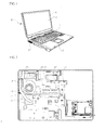
- FIG. 1 is a perspective view showing an external appearance of a general computer
- FIG. 2 is a plan view showing the internal configuration of the computer.
- a computer 1 generally comprises a main body 3 and a display unit 5.
- the display unit 5 is provided with a display screen 6 having a liquid crystal panel, and is connected to a rear portion of the main body 3 to be brought into contact with an upper surface of the man body 3 or unfolded with respect thereto.
- the display unit 5 is formed in the shape of a generally flat hexahedral plate.
- the main body 3 is in the shape of a generally flat hexahedral plate, a key board section 7 is provided on the upper surface of the main body.
- a ventilating hole 9 is formed on one side of an outer surface of the main body 3 to exhaust heat generated in the main body to the outside. Air stream containing heat generated in the main body 3 passes through the ventilating hole 3.
- a main board 10 is installed in the main body 3.
- a plurality of heat-generating elements 11 are mounted on the main board 10.
- the heat-generating elements 11 include, for example, a microprocessor, a chipset, a graphic chip and the like.
- a heat-radiating fan 20 is provided in the main body 3 to exhaust heat generated from the heat-generating components 11 to the outside.
- the heat-radiating fan 20 serves to form air stream directed toward the ventilating hole 9 in the main body 3.
- a cooling fin 23 is provided between the ventilating hole 9 and the heat-radiating fan 20.
- a plurality of fin gaps through which air stream can pass are formed on the cooling fin 23.
- One ends of heat pipes 25 are in thermal contact with an upper surface of the cooling fin 23.
- the other ends of the hat pipes 25 are in thermal contact with the heat-generating components 11.
- the heat pipes 25 serve to transfer heat of the heat-generating components 11 to the cooling fin 23.
- Air stream to be exhausted to the outside via the ventilating hole 9 is formed by the driving of the heat-radiating fan 20. At this time, the air stream, which contains the heat transferred from the cooling fin 23 to the air stream while the air stream passes through the cooling fin 23, is exhausted to the outside.
- a filter is installed at a location adjacent to the cooling fin 23 for filtering dust.
- a user should replace or wash the filter used.
- the present invention is conceived to solve the aforementioned problems in a related art.
- An object of the present invention is to automatically eliminate dust accumulated on a cooling fine of a computer to keep the cooling fin clean.
- Another object of the present invention is to easily clean a cooling fin of a computer.
- a dust eliminator for a computer which comprises a main body having an internal space and a ventilating hole; a heat-radiating fan provided in the internal space of the main body to form an air stream for exhausting heat in the main body to the outside; a cooling fin provided between the ventilating hole and the heat-radiating fan, the cooling fin exchanging heat with the air stream passing therethrough; and a vibration-generating element transmitting vibration to the cooling fin to shake off dust accumulated on the cooing fin.
- the dust eliminator may further comprise a power supplying unit for supplying the main body with power; and a switch for selectively supplying power from the power supplying unit to the vibration-generating element according to a signal of the control unit, wherein a driving duration of the vibration-generating element and the number of times the vibration-generating element is driven are controlled by the control unit.
- the switch is configured to be operated by a user, whereby the user can drive the vibration-generating element if necessary.
- the vibration-generating element is a piezoelectric element provided at one side of the cooling fin.
- a method of controlling a dust eliminator which comprises shaking off dust accumulated on a cooling fin by transmitting vibration to the cooling fin caused by a vibration-generating element provided at one side of the cooling fin; and forming an air stream with a heat-radiating fan provided in a main body; performing heat exchange between the air stream and the cooling fin while the air stream passes through the cooling fin; and exhausting the air stream to the outside of the main body along with the dust separated from the cooling fin, wherein driving of the vibration-generating element cooperates with the driving of the heat-radiating fan.
- the vibration-generating element may be driven for a predetermined time from an initial time at which the main body is required to be powered on.
- the vibration-generating element may be driven for a predetermined time from an initial time at which the main body is required to be powered off.
- the vibration-generating element may be driven for a predetermined time whenever the main body is required to be powered on and powered off.
- a dust eliminator for a computer and a control method thereof according to the present invention as described above in detail can obtain the following effects.
- vibration of the vibration-generating element attached to the cooling fin causes dust accumulated on the cooling fin to be shaken off, and the dust separated from the cooling fin is then exhausted out of the main body along with air stream formed by the heat-radiating fan.
- the driving of the vibration-generating element is controlled by the control unit of the main body. Accordingly, there are advantageous effects in that the cooling fin is always kept clean and heat exchange is well performed by the cooling fin to thereby enhance the cooling efficient of the main body.
- the cooling fin is easily cleaned to thereby increase the convenience in use.
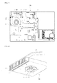
- FIG. 3 is a plan view showing the internal configuration of a computer according to the present invention
- FIG. 4 is a perspective view showing the configuration of a dust eliminator for the computer according to the present invention
- FIG. 5 is a block diagram illustrating the operation of the dust eliminator for the computer according to the present invention.
- a ventilating hole 32 is formed on one side of a main body 30 of the computer.
- the ventilating hole 32 causes interior and exterior of the main body 30 to communicate with each other.
- a plurality of heat-generating components 33 are provided inside of the main body 30.
- the above heat-generating components 33 include a chipset, a control unit 40 to be described below, and the like.
- the control unit 40 is provided in the main body 30.
- the control unit 40 is also called as a central processing unit (CPU).
- the control unit 40 processes all kinds of signals to control various components of the main body 30.
- the control unit 40 controls driving of a heat-radiating fan 50, which will be described later.
- the control unit 40 detects a temperature in the main body 30, or detects the active operation of the main body 30, to thereby drive the heat-radiating fan 50. It will be apparent that the control unit 40 can periodically drive the heat-radiating fan 50.
- control unit 40 serves to control driving of a vibration-generating element 70 to be described later. This will be illustrated in more detail later.
- the heat-radiating fan 50 is provided at a location adjacent to the ventilating hole 32.
- the heat-radiating fan 50 serves to form a certain air stream inside of the main body 30.
- the heat-radiating fan 50 comprises a fan housing 51 and rotating blades 52, wherein a suction hole 53 is formed on one surface of the fan housing 51.
- a discharging hole (not shown) is formed on a side surface of the fan housing 51, that is, on a portion opposite to the ventilating hole 32, so that air sucked through the suction hole 53 is exhausted through the discharging hole by rotation of the rotating blades 52.
- a cooling fin 60 is provided between the ventilating hole 32 and the heat-radiating fan 50.
- the cooling fin 60 is configured such that air can pass through the cooling fin. In other words, a plurality of micro gaps are formed in the cooling fin 60.
- the cooling fin 60 is placed between the discharging hole of the fan housing 51 and the ventilating hole 32, thereby allowing heat-exchange to be performed while air discharged from the discharging hole flows to the ventilating hole 32.
- the vibration-generating element 70 is provided at one side of the cooling fin 60.
- the vibration-generating element 70 serves to transmit vibration to the cooling fin 60 to thereby shake off fine dusts accumulated on the cooling fin 60.
- the vibration-generating element 70 includes a piezoelectric element, a vibration motor and the like.
- the piezoelectric element is changed in shape according to an electrical signal to generate vibration when electric power is applied to the piezoelectric element.
- the vibration motor is a motor for converting an electrical energy into a mechanical vibration energy using a principle of generating electromagnetic force.
- the vibration-generating element 70 is attached to a lower surface of the cooling fin 60. More specifically, the vibration-generating element 70 is attached to the surface of the cooling fin 60 that is opposite to a surface thereof contacting with a heat pipe 80 to be described later. However, since the vibration-generating element 70 sufficiently functions in it can transmit vibration to the cooling fin 60, there is no necessarily need to attach the vibration-generating element to the lower surface of the cooling fin 60. It is only preferable that the vibration-generating element 70 be provided at a position such that the gaps through which air stream can pass are not blocked and an interference with the heat pipe 80 is not generated.
- the heat pipe 80 serves to transfer heat generated in the heat-generating components 33 to the cooling fin 60. To this end, both ends of the heat pipe 80 are in thermal contact with the heat-generating components 33 and the cooling fin 60, respectively,
- a power supplying unit 90 serves to supply power to the main body 30.
- a switch 92 is provided between the power supplying unit 90 and the vibration-generating element 70, and the switch 92 is operated according to the signal of the control unit 40. That is, the switch 92 is operated according to the signal of the control unit 40 and thus the power of the power supplying unit 90 is selectively transmitted to the vibration-generating element 70, so that the driving of the vibration-generating element 70 is controlled.
- the information for determining the number of times the vibration-generating member 70 is driven, a driving timing of the vibration-generating member 70, or a duration for each driving of the vibration-generating member 70 may be inputted into the control unit 40 in advance.
- the information is stored in the control unit 40 so that the vibration-generating element 70 can be driven for a certain time from an initial time at which electric power is supplied to the main body 30.
- the vibration-generating element 70 may be driven several times periodically at regular intervals, may be driven in cooperation with the driving of the heat-radiating fan 50 and may be operated according to the temperature of the heat-generating components 33.
- a user can operate the switch 92 manually. That is, in order to eliminate dust on the cooling fin 60, the user can operate the switch 92 to drive the vibration-generating element 70, if necessary.
- the vibration-generating element 70 is driven by residual power in the main body 30 to transmit vibration to the cooling fin 60. This is to minimize vibration transmitted to the cooling fin 60 while the user substantially operates the computer, thereby not preventing the user from using the computer.
- An AC/DC converter 94 serves to convert the power supplied from the power supplying unit 90 into power suitable for the vibration-generating element 70.
- the heat-radiating fan 50 In order to radiate the heat generated in a process of operating the computer, the heat-radiating fan 50 is driven. Air sucked through the suction hole 53 by the driving of the heat-radiating fan 50 passes through the cooling fin 60 and then exhausted to the outside through the ventilating hole 32a, wherein while the air passes through the cooling fin 60, heat is exchanged therebetween.
- the heat generated in the heat-generating components 33 is transferred to the cooling fin 60 through the heat pipe 80. Then, the cooling fin 60, whose temperature has been raised by the heat pipe 80, is cooled through a heat transferring process between the cooling fin 60 and the air passing therethrough.
- the cooling fin 60 is covered with foreign substance or dust contained in the air passing through the cooling fin 60. If the dust is accumulated on the cooling fin 60, the air stream generated by the heat-radiating fan 50 cannot smoothly pass through the cooling fin 60, so that the heat exchange does not occur sufficiently.
- the vibration-generating element 70 attached to the lower surface of the cooling fin 60 vibrates the cooling fin 60, thereby causing dust accumulated on the cooling fin 60 to be separated therefrom. Then, the air stream generated by the heat-radiating fan 50 is exhausted to the outside together with the dust separated from the cooling fin 50.
- the driving of the vibration-generating element 70 is controlled by the control unit 40. More specifically, the control unit 40 operates the switch 92, so that the power supplied from the power supplying unit 90 to the vibration-generating element 70 is adjusted to thereby control the driving of the vibration-generating element 70. In addition, the driving of the vibration-generating element 70 may be in cooperation with the driving of the heat-radiating fan 50.
- the information for operating the switch 92 is stored in the control unit 40 in advance.
- the vibration-generating element 70 is driven for a certain time when the main body 30 is required to be powered on or the main body 30 is required to be powered off.
- the vibration-generating element 70 can be driven for a certain time whenever the main body 30 is required to be powered on and powered off.
- the rotating blades 52 provided in the heat-radiating fan 50 are rotated at the highest rotating speed while the vibration-generating element 70 is supplied with power. This is to eliminate the dust, which is separated from the cooling fin 60 by the vibration of the vibration-generating element 70, by stronger air stream.
- a rotating speed of the rotating blades 52 provided in the heat-radiating fan 50 may be varied while the vibration-generating element 70 is supplied with power. This is to eliminate the dust, which is separated from the cooling fin 60, by air stream with a varied strength.
- the user may operate directly the switch 92 to drive the vibration-generating element 70.
- the switch 92 may be operated by pushing a function key provided on a key board (not shown) that is a separate input device.
- the vibration-generating element 70 is supplied with power for a certain time when the detected temperature of the heat-generating element 33 provided in the main body 30, particularly, the detected temperature of the CPU according to use of the CPU exceeds the allowable temperature. Allowable temperature ranges of the CPU according to use of the CPU are listed at the following table. Referring to the table, since an allowable temperature range of the CPU is 30 ⁇ 50 °C when the use of the CPU is 20%, the vibration-generating element 70 is supplied with power while the detected temperature exceeds 50 °C. Table 1.
- Allowable temperature range of CPU according to use of CPU Use of CPU (%) Allowable temperature range of CPU(°C) 0 ⁇ 20% 30 ⁇ 50 °C 20 ⁇ 50% 40 ⁇ 65 °C 50 ⁇ 90% 55 ⁇ 75 °C 90 ⁇ 100% 65 ⁇ 85 °C
- the vibration-generating element 70 is periodically supplied with power. That is, the vibration-generating element 70 may be supplied with power once a week or once a month.
- a rotating speed of the rotating blades 52 provided in the heat-radiating fan 50 is detected, and then, the vibration-generating element 70 is supplied with power for a certain time when the rotating speed of the rotating blades is a maximum value.
- the dust eliminator of the present invention can be applied to all kinds of electronic appliances provided with a cooling fin and requiring elimination of dust accumulated on the cooling fin as well as the computer.
- the dust eliminator of the present invention can be applied for eliminating dust accumulated on micro components requiring elimination of dust in addition to the cooling fin.
Abstract
Description
- The present invention relates to a computer, and more particularly, to a dust eliminator for eliminating dust and foreign substance adhering to a cooling fin, and a control method thereof.
-
FIG. 1 is a perspective view showing an external appearance of a general computer, andFIG. 2 is a plan view showing the internal configuration of the computer. As shown in the figures, acomputer 1 generally comprises amain body 3 and adisplay unit 5. In general, thedisplay unit 5 is provided with adisplay screen 6 having a liquid crystal panel, and is connected to a rear portion of themain body 3 to be brought into contact with an upper surface of theman body 3 or unfolded with respect thereto. Like themain body 3, thedisplay unit 5 is formed in the shape of a generally flat hexahedral plate. - The
main body 3 is in the shape of a generally flat hexahedral plate, akey board section 7 is provided on the upper surface of the main body. Aventilating hole 9 is formed on one side of an outer surface of themain body 3 to exhaust heat generated in the main body to the outside. Air stream containing heat generated in themain body 3 passes through theventilating hole 3. - As shown in
Fig. 2 , a main board 10 is installed in themain body 3. A plurality of heat-generatingelements 11 are mounted on the main board 10. The heat-generatingelements 11 include, for example, a microprocessor, a chipset, a graphic chip and the like. - In the meantime, a heat-radiating
fan 20 is provided in themain body 3 to exhaust heat generated from the heat-generatingcomponents 11 to the outside. The heat-radiatingfan 20 serves to form air stream directed toward theventilating hole 9 in themain body 3. - A
cooling fin 23 is provided between theventilating hole 9 and the heat-radiatingfan 20. A plurality of fin gaps through which air stream can pass are formed on thecooling fin 23. One ends ofheat pipes 25 are in thermal contact with an upper surface of thecooling fin 23. The other ends of thehat pipes 25 are in thermal contact with the heat-generatingcomponents 11. Theheat pipes 25 serve to transfer heat of the heat-generatingcomponents 11 to thecooling fin 23. - A process of cooling the computer constructed as described above will be described. Air stream to be exhausted to the outside via the
ventilating hole 9 is formed by the driving of the heat-radiatingfan 20. At this time, the air stream, which contains the heat transferred from thecooling fin 23 to the air stream while the air stream passes through thecooling fin 23, is exhausted to the outside. - However, the above related art has the following problems.
- Due to the driving of the heat-radiating
fan 20, fine dust and foreign substance are accumulated in the gaps of thecooling fin 23 that is passages of the air stream. In particular, the gaps of thecooling fin 23 are clogged with the fine dust accumulated for a long time, so that the air stream formed by the heat-radiatingfan 20 cannot pass through the gaps. Consequently, it is impossible to radiate the heat generated in the computer. - In order to solve the problem, a filter is installed at a location adjacent to the
cooling fin 23 for filtering dust. However, there is inconvenience in that a user should replace or wash the filter used. - The present invention is conceived to solve the aforementioned problems in a related art. An object of the present invention is to automatically eliminate dust accumulated on a cooling fine of a computer to keep the cooling fin clean.
- Another object of the present invention is to easily clean a cooling fin of a computer.
- According to an aspect of the present invention for achieving the objects, there is provided a dust eliminator for a computer, which comprises a main body having an internal space and a ventilating hole; a heat-radiating fan provided in the internal space of the main body to form an air stream for exhausting heat in the main body to the outside; a cooling fin provided between the ventilating hole and the heat-radiating fan, the cooling fin exchanging heat with the air stream passing therethrough; and a vibration-generating element transmitting vibration to the cooling fin to shake off dust accumulated on the cooing fin.
- The dust eliminator may further comprise a power supplying unit for supplying the main body with power; and a switch for selectively supplying power from the power supplying unit to the vibration-generating element according to a signal of the control unit,
wherein a driving duration of the vibration-generating element and the number of times the vibration-generating element is driven are controlled by the control unit. - The switch is configured to be operated by a user, whereby the user can drive the vibration-generating element if necessary.
- The vibration-generating element is a piezoelectric element provided at one side of the cooling fin.
- According to another aspect of the present invention, there is provided a method of controlling a dust eliminator, which comprises shaking off dust accumulated on a cooling fin by transmitting vibration to the cooling fin caused by a vibration-generating element provided at one side of the cooling fin; and forming an air stream with a heat-radiating fan provided in a main body; performing heat exchange between the air stream and the cooling fin while the air stream passes through the cooling fin; and exhausting the air stream to the outside of the main body along with the dust separated from the cooling fin, wherein driving of the vibration-generating element cooperates with the driving of the heat-radiating fan.
- The vibration-generating element may be driven for a predetermined time from an initial time at which the main body is required to be powered on.
- The vibration-generating element may be driven for a predetermined time from an initial time at which the main body is required to be powered off.
- The vibration-generating element may be driven for a predetermined time whenever the main body is required to be powered on and powered off.
- Rotating a blade provided in the heat-radiating fan at the blade's highest rotating speed while the vibration-generating element is driven.
- Yarying a speed of a rotating blade provided in the heat-radiating fan while the vibration-generating element is driven.
- A dust eliminator for a computer and a control method thereof according to the present invention as described above in detail can obtain the following effects.
- In the present invention, vibration of the vibration-generating element attached to the cooling fin causes dust accumulated on the cooling fin to be shaken off, and the dust separated from the cooling fin is then exhausted out of the main body along with air stream formed by the heat-radiating fan. Also, the driving of the vibration-generating element is controlled by the control unit of the main body. Accordingly, there are advantageous effects in that the cooling fin is always kept clean and heat exchange is well performed by the cooling fin to thereby enhance the cooling efficient of the main body.
- Further, in the present invention, there is no need to disassemble the main body or separate the cooling fin from the main body for cleaning the cooling fin. Therefore, the cooling fin is easily cleaned to thereby increase the convenience in use.
-
FIG. 1 is a perspective view showing an external appearance of a general computer; -
FIG. 2 is a plan view showing the internal configuration of the general computer; -
FIG. 3 is a plan view showing the internal configuration of a computer according to the present invention; -
FIG. 4 is a perspective view showing the configuration of a dust eliminator for the computer according to the present invention; and -
FIG. 5 is a block diagram illustrating the operation of the dust eliminator for the computer according to the present invention. - Hereinafter, a preferred embodiment of a dust eliminator for a computer and a control method thereof according to the present invention will be described in more detail with reference to the accompanying drawings.
-
FIG. 3 is a plan view showing the internal configuration of a computer according to the present invention,FIG. 4 is a perspective view showing the configuration of a dust eliminator for the computer according to the present invention, andFIG. 5 is a block diagram illustrating the operation of the dust eliminator for the computer according to the present invention. - As shown in the figures, a
ventilating hole 32 is formed on one side of amain body 30 of the computer. The ventilatinghole 32 causes interior and exterior of themain body 30 to communicate with each other. A plurality of heat-generatingcomponents 33 are provided inside of themain body 30. The above heat-generatingcomponents 33 include a chipset, acontrol unit 40 to be described below, and the like. - The
control unit 40 is provided in themain body 30. Thecontrol unit 40 is also called as a central processing unit (CPU). - The
control unit 40 processes all kinds of signals to control various components of themain body 30. For example, thecontrol unit 40 controls driving of a heat-radiatingfan 50, which will be described later. Thecontrol unit 40 detects a temperature in themain body 30, or detects the active operation of themain body 30, to thereby drive the heat-radiatingfan 50. It will be apparent that thecontrol unit 40 can periodically drive the heat-radiatingfan 50. - In this embodiment, the
control unit 40 serves to control driving of a vibration-generatingelement 70 to be described later. This will be illustrated in more detail later. - In the meantime, the heat-radiating
fan 50 is provided at a location adjacent to theventilating hole 32. The heat-radiatingfan 50 serves to form a certain air stream inside of themain body 30. To this end, the heat-radiatingfan 50 comprises afan housing 51 androtating blades 52, wherein asuction hole 53 is formed on one surface of thefan housing 51. Although not shown, a discharging hole (not shown) is formed on a side surface of thefan housing 51, that is, on a portion opposite to theventilating hole 32, so that air sucked through thesuction hole 53 is exhausted through the discharging hole by rotation of therotating blades 52. - A cooling
fin 60 is provided between the ventilatinghole 32 and the heat-radiatingfan 50. The coolingfin 60 is configured such that air can pass through the cooling fin. In other words, a plurality of micro gaps are formed in the coolingfin 60. The coolingfin 60 is placed between the discharging hole of thefan housing 51 and theventilating hole 32, thereby allowing heat-exchange to be performed while air discharged from the discharging hole flows to theventilating hole 32. - In addition, the vibration-generating
element 70 is provided at one side of the coolingfin 60. The vibration-generatingelement 70 serves to transmit vibration to the coolingfin 60 to thereby shake off fine dusts accumulated on the coolingfin 60. The vibration-generatingelement 70 includes a piezoelectric element, a vibration motor and the like. The piezoelectric element is changed in shape according to an electrical signal to generate vibration when electric power is applied to the piezoelectric element. Also, the vibration motor is a motor for converting an electrical energy into a mechanical vibration energy using a principle of generating electromagnetic force. - In this embodiment, the vibration-generating
element 70 is attached to a lower surface of the coolingfin 60. More specifically, the vibration-generatingelement 70 is attached to the surface of the coolingfin 60 that is opposite to a surface thereof contacting with aheat pipe 80 to be described later. However, since the vibration-generatingelement 70 sufficiently functions in it can transmit vibration to the coolingfin 60, there is no necessarily need to attach the vibration-generating element to the lower surface of the coolingfin 60. It is only preferable that the vibration-generatingelement 70 be provided at a position such that the gaps through which air stream can pass are not blocked and an interference with theheat pipe 80 is not generated. - The
heat pipe 80 serves to transfer heat generated in the heat-generatingcomponents 33 to the coolingfin 60. To this end, both ends of theheat pipe 80 are in thermal contact with the heat-generatingcomponents 33 and the coolingfin 60, respectively, - In the meantime, a
power supplying unit 90 serves to supply power to themain body 30. In addition, aswitch 92 is provided between thepower supplying unit 90 and the vibration-generatingelement 70, and theswitch 92 is operated according to the signal of thecontrol unit 40. That is, theswitch 92 is operated according to the signal of thecontrol unit 40 and thus the power of thepower supplying unit 90 is selectively transmitted to the vibration-generatingelement 70, so that the driving of the vibration-generatingelement 70 is controlled. - The information for determining the number of times the vibration-generating
member 70 is driven, a driving timing of the vibration-generatingmember 70, or a duration for each driving of the vibration-generatingmember 70 may be inputted into thecontrol unit 40 in advance. In this embodiment, for example, the information is stored in thecontrol unit 40 so that the vibration-generatingelement 70 can be driven for a certain time from an initial time at which electric power is supplied to themain body 30. However, the present invention is not necessarily limited thereto, but the vibration-generatingelement 70 may be driven several times periodically at regular intervals, may be driven in cooperation with the driving of the heat-radiatingfan 50 and may be operated according to the temperature of the heat-generatingcomponents 33. - In addition, a user can operate the
switch 92 manually. That is, in order to eliminate dust on the coolingfin 60, the user can operate theswitch 92 to drive the vibration-generatingelement 70, if necessary. - In addition, when the user finishes using the computer and then turns-off it, it is possible to shake off dust accumulated on the cooling
fin 60. For example, when the supply of power to themain body 30 is interrupted, the vibration-generatingelement 70 is driven by residual power in themain body 30 to transmit vibration to the coolingfin 60. This is to minimize vibration transmitted to the coolingfin 60 while the user substantially operates the computer, thereby not preventing the user from using the computer. - An AC/
DC converter 94 serves to convert the power supplied from thepower supplying unit 90 into power suitable for the vibration-generatingelement 70. - Hereinafter, a function of the dust eliminator for a computer according to this embodiment having the structure as described above will be illustrated in detail. In
Fig. 4 , air stream in this embodiment is indicated by arrows. - In order to radiate the heat generated in a process of operating the computer, the heat-radiating
fan 50 is driven. Air sucked through thesuction hole 53 by the driving of the heat-radiatingfan 50 passes through the coolingfin 60 and then exhausted to the outside through the ventilating hole 32a, wherein while the air passes through the coolingfin 60, heat is exchanged therebetween. - In the meantime, the heat generated in the heat-generating
components 33 is transferred to the coolingfin 60 through theheat pipe 80. Then, the coolingfin 60, whose temperature has been raised by theheat pipe 80, is cooled through a heat transferring process between the coolingfin 60 and the air passing therethrough. - At this time, the cooling
fin 60 is covered with foreign substance or dust contained in the air passing through the coolingfin 60. If the dust is accumulated on the coolingfin 60, the air stream generated by the heat-radiatingfan 50 cannot smoothly pass through the coolingfin 60, so that the heat exchange does not occur sufficiently. In this embodiment, the vibration-generatingelement 70 attached to the lower surface of the coolingfin 60 vibrates the coolingfin 60, thereby causing dust accumulated on the coolingfin 60 to be separated therefrom. Then, the air stream generated by the heat-radiatingfan 50 is exhausted to the outside together with the dust separated from the coolingfin 50. - The driving of the vibration-generating
element 70 is controlled by thecontrol unit 40. More specifically, thecontrol unit 40 operates theswitch 92, so that the power supplied from thepower supplying unit 90 to the vibration-generatingelement 70 is adjusted to thereby control the driving of the vibration-generatingelement 70. In addition, the driving of the vibration-generatingelement 70 may be in cooperation with the driving of the heat-radiatingfan 50. - Hereinafter, various embodiments of the method of controlling the dust eliminator will be described.
- The information for operating the
switch 92 is stored in thecontrol unit 40 in advance. Preferably, the vibration-generatingelement 70 is driven for a certain time when themain body 30 is required to be powered on or themain body 30 is required to be powered off. Of course, it will be apparent that the vibration-generatingelement 70 can be driven for a certain time whenever themain body 30 is required to be powered on and powered off. - This is to shake off dust of the cooling
fin 60 before the heat-radiatingfan 50 is driven. Also, this is to prevent the vibration from being transmitted to themain body 30 when a user utilizes themain body 30. - According to this embodiment having the aforementioned configuration, when the
main body 30 is turned on and off, the dust is separated from the coolingfin 60 by the vibration of the vibration-generatingelement 70. In addition, the air stream formed by the heat-radiatingfan 50 driven during the operation of themain body 30 is exhausted to the outside through the ventilatinghole 32 together with the dust separated from the coolingfin 60. As a result, dust accumulated on the coolingfin 60 is not remained in themain body 30, but exhausted to the outside. - At this time, the
rotating blades 52 provided in the heat-radiatingfan 50 are rotated at the highest rotating speed while the vibration-generatingelement 70 is supplied with power. This is to eliminate the dust, which is separated from the coolingfin 60 by the vibration of the vibration-generatingelement 70, by stronger air stream. - In addition, a rotating speed of the
rotating blades 52 provided in the heat-radiatingfan 50 may be varied while the vibration-generatingelement 70 is supplied with power. This is to eliminate the dust, which is separated from the coolingfin 60, by air stream with a varied strength. - According to this embodiment, since dust of the cooling
fin 60 is eliminated by the vibration-generatingelement 70, there is no need to clean the coolingfin 60. In addition, there is no need to disassemble themain body 30 or to separate the coolingfin 60 from themain body 30 for cleaning the coolingfin 60. - When the driving of the vibration-generating
element 70 caused by an instruction of thecontrol unit 40 is insufficient, the user may operate directly theswitch 92 to drive the vibration-generatingelement 70. Theswitch 92 may be operated by pushing a function key provided on a key board (not shown) that is a separate input device. - The vibration-generating
element 70 is supplied with power for a certain time when the detected temperature of the heat-generatingelement 33 provided in themain body 30, particularly, the detected temperature of the CPU according to use of the CPU exceeds the allowable temperature. Allowable temperature ranges of the CPU according to use of the CPU are listed at the following table. Referring to the table, since an allowable temperature range of the CPU is 30∼50 °C when the use of the CPU is 20%, the vibration-generatingelement 70 is supplied with power while the detected temperature exceeds 50 °C.Table 1. Allowable temperature range of CPU according to use of CPU Use of CPU (%) Allowable temperature range of CPU(°C) 0 ∼ 20% 30 ∼ 50 ° C 20 ∼ 50% 40 ∼ 65 ° C 50 ∼ 90% 55 ∼ 75 ° C 90 ∼ 100% 65 ∼ 85 °C - The vibration-generating
element 70 is periodically supplied with power. That is, the vibration-generatingelement 70 may be supplied with power once a week or once a month. - A rotating speed of the
rotating blades 52 provided in the heat-radiatingfan 50 is detected, and then, the vibration-generatingelement 70 is supplied with power for a certain time when the rotating speed of the rotating blades is a maximum value. - The scope of the present invention is not limited to the embodiment described above but is defined by the appended claims. It will be apparent that those skilled in the art can make various modifications and changes thereto within the scope of the invention defined by the claims.
- For example, the dust eliminator of the present invention can be applied to all kinds of electronic appliances provided with a cooling fin and requiring elimination of dust accumulated on the cooling fin as well as the computer.
- Also, the dust eliminator of the present invention can be applied for eliminating dust accumulated on micro components requiring elimination of dust in addition to the cooling fin.
Claims (15)
- A dust eliminator for a computer, comprising:a main body having an internal space and a ventilating hole;a heat-radiating fan provided in the internal space of the main body to form an air stream for exhausting heat in the main body to the outside:a cooling fin provided between the ventilating hole and the heat-radiating fan, the cooling fin exchanging heat with the air stream passing therethrough; anda vibration-generating element transmitting vibration to the cooling fin to shake off dust accumulated on the cooing fin.
- The dust eliminator as claimed in claim 1, further comprising a control unit in the main body; a power supplying unit for supplying the main body with power; and a switch for selectively supplying power from the power supplying unit to the vibration-generating element according to a signal of the control unit,
wherein a driving duration of the vibration-generating element and the number of times the vibration-generating element is driven are controlled by the control unit. - The dust eliminator as claimed in claim 2, wherein the switch is configured to be operated by a user, whereby the user can drive the vibration-generating element.
- The dust eliminator as claimed in any one of claims 1 to 3, wherein the vibration-generating element is a piezoelectric element provided at one side of the cooling fin.
- The dust eliminator as claimed in any one of claims 1 to 3, wherein the vibration-generating element is a vibration motor provided at one side of the cooling fin.
- The dust eliminator as claimed in any one of claims 1 to 3, further comprising a heat pipe contacting one surface of the cooling fin for transferring heat generated in a heat-generating component provided in the main body to the cooling fin, wherein the vibration-generating element is in contact with one surface of the cooling fin opposite to a surface thereof contacting with the heat pipe.
- A method of controlling a dust eliminator, comprising:shaking off dust accumulated on a cooling fin by transmitting vibration to the cooling fin caused by a vibration-generating element provided at one side of the cooling fin; andforming an air stream with a heat-radiating fan provided in a main body;performing heat exchange between the air stream and the cooling fin while the air stream passes through the cooling fin; andexhausting the air stream to the outside of the main body along with the dust separated from the cooling fin,wherein driving of the vibration-generating element cooperates with the driving of the heat-radiating fan.
- The method as claimed in claim 7, wherein the vibration-generating element is driven for a predetermined time from an initial time at which the main body is required to be powered on.
- The method as claimed in claim 7, wherein the vibration-generating element is driven for a predetermined time from an initial time at which the main body is required to be powered off.
- The method as claimed in claim 7, wherein the vibration-generating element is driven for a predetermined time whenever the main body is required to be powered on and powered off.
- The method as claimed in any one of claims 7 to 10, further comprising rotating a blade provided in the heat-radiating fan at the blade's highest rotating speed while the vibration-generating element is driven.
- The method as claimed in any one of claims 7 to 10, further comprising varying a speed of a rotating blade provided in the heat-radiating fan while the vibration-generating element is driven.
- The method as claimed in claim 7, further comprising driving the vibration-generating element for a predetermined time when the temperature of a heat-generating element provided at one side of the main body is detected and exceeds an allowable temperature.
- The method as claimed in claim 7, further comprising periodically driving the vibration-generating element.
- The method as claimed in claim 7, further comprising driving the vibration-generating element for a predetermined time when a rotating blade provided in the heat-radiating fan is rotated at the blade's highest rotating speed.
Applications Claiming Priority (1)
| Application Number | Priority Date | Filing Date | Title |
|---|---|---|---|
| KR20080041492A KR101494007B1 (en) | 2008-05-02 | 2008-05-02 | A dust eliminator for computer and control method thereof |
Publications (3)
| Publication Number | Publication Date |
|---|---|
| EP2113821A2 true EP2113821A2 (en) | 2009-11-04 |
| EP2113821A3 EP2113821A3 (en) | 2009-11-25 |
| EP2113821B1 EP2113821B1 (en) | 2017-05-03 |
Family
ID=40905114
Family Applications (1)
| Application Number | Title | Priority Date | Filing Date |
|---|---|---|---|
| EP08166773.5A Not-in-force EP2113821B1 (en) | 2008-05-02 | 2008-10-16 | Dust eliminator for computer and control method thereof |
Country Status (4)
| Country | Link |
|---|---|
| US (1) | US8400766B2 (en) |
| EP (1) | EP2113821B1 (en) |
| KR (1) | KR101494007B1 (en) |
| CN (1) | CN101571732B (en) |
Cited By (2)
| Publication number | Priority date | Publication date | Assignee | Title |
|---|---|---|---|---|
| WO2018013668A1 (en) | 2016-07-12 | 2018-01-18 | Alexander Poltorak | System and method for maintaining efficiency of a heat sink |
| EP3539671A1 (en) * | 2018-03-14 | 2019-09-18 | Nokia Technologies Oy | Charging of an electrically conductive object |
Families Citing this family (23)
| Publication number | Priority date | Publication date | Assignee | Title |
|---|---|---|---|---|
| US9228785B2 (en) | 2010-05-04 | 2016-01-05 | Alexander Poltorak | Fractal heat transfer device |
| US10852069B2 (en) | 2010-05-04 | 2020-12-01 | Fractal Heatsink Technologies, LLC | System and method for maintaining efficiency of a fractal heat sink |
| TW201144982A (en) * | 2010-06-09 | 2011-12-16 | Hon Hai Prec Ind Co Ltd | Computer capable of automatically cleaning dust |
| CN102279620A (en) * | 2010-06-10 | 2011-12-14 | 鸿富锦精密工业(深圳)有限公司 | Computer device provided with automatic dedusting function |
| WO2012014640A1 (en) * | 2010-07-26 | 2012-02-02 | Canon Kabushiki Kaisha | Vibration wave motor |
| US8709140B2 (en) | 2011-03-29 | 2014-04-29 | Hewlett-Packard Development Company, L.P. | Particulate removal |
| CN103157626B (en) * | 2011-12-13 | 2016-10-05 | 技嘉科技股份有限公司 | Dust arrester |
| CN103433247B (en) * | 2013-08-07 | 2016-03-30 | 华为数字技术(苏州)有限公司 | Electronic equipment dust collection method, device and electronic equipment |
| US9459669B2 (en) * | 2014-01-28 | 2016-10-04 | Dell Products L.P. | Multi-component shared cooling system |
| US20170059263A1 (en) * | 2014-03-31 | 2017-03-02 | Intel Corporation | Sonic dust remediation |
| JP6323175B2 (en) * | 2014-05-29 | 2018-05-16 | 富士通株式会社 | Electronic device and filter device |
| CN105222105A (en) * | 2014-06-12 | 2016-01-06 | 奇鋐科技股份有限公司 | LED lamp dedusting cooling system |
| CN104438223A (en) * | 2014-12-01 | 2015-03-25 | 广西大学 | Computer dust remover |
| CN112196812B (en) * | 2015-05-20 | 2022-06-07 | 菲舍尔和佩克尔应用有限公司 | Fan or pump arrangement and method of operation |
| TWI536152B (en) * | 2015-05-26 | 2016-06-01 | 鴻海精密工業股份有限公司 | Dedusting structure and electronic system using same |
| JP6227610B2 (en) * | 2015-10-02 | 2017-11-08 | ファナック株式会社 | Cooling device having a function of detecting clogging of radiating fins |
| CN111433549A (en) | 2017-07-17 | 2020-07-17 | 分形散热器技术有限责任公司 | Multi-fractal heat sink system and method |
| CN110948140A (en) * | 2018-09-26 | 2020-04-03 | 天津龙净环保科技有限公司 | Railing welding auxiliary robot |
| CN111054668B (en) * | 2019-11-20 | 2020-11-24 | 浙江无极互联科技有限公司 | Dust cleaning device for computer mainframe box |
| CN111799928B (en) * | 2020-07-15 | 2021-10-12 | 重庆新登奇机电技术有限公司 | Industrial robot motor box with heat dissipation function |
| US11924994B2 (en) * | 2021-07-16 | 2024-03-05 | Dell Products L.P. | Managing a heatsink of an information handling system |
| CN114629399B (en) * | 2022-03-22 | 2023-01-31 | 江苏久祥汽车电器集团有限公司 | Environment-friendly automobile generator regulator support |
| CN117251342B (en) * | 2023-11-17 | 2024-02-06 | 合肥天帷信息安全技术有限公司 | Big data-based network monitoring equipment |
Citations (2)
| Publication number | Priority date | Publication date | Assignee | Title |
|---|---|---|---|---|
| JP2006332377A (en) | 2005-05-26 | 2006-12-07 | Fujitsu Ltd | Cooling structure |
| US20070058346A1 (en) | 2005-09-15 | 2007-03-15 | Asustek Computer Inc. | Thermal module capable of removing dust from heat sink fins by vibration and electronic device thereof |
Family Cites Families (12)
| Publication number | Priority date | Publication date | Assignee | Title |
|---|---|---|---|---|
| US6100654A (en) * | 1998-01-29 | 2000-08-08 | Canon Kabushiki Kaisha | Driving device for a vibration type motor |
| DE19916595B4 (en) * | 1999-04-13 | 2005-03-31 | Siemens Ag | Arrangement for cooling an electrical assembly and for cooling an electrically operated technical device |
| KR100465793B1 (en) * | 2002-06-20 | 2005-01-13 | 삼성전자주식회사 | Computer |
| JP2004219852A (en) | 2003-01-17 | 2004-08-05 | Hitachi Ltd | Projection type video display device and polarizing plate device used for the same |
| EP1531384A3 (en) | 2003-11-14 | 2006-12-06 | LG Electronics Inc. | Cooling apparatus for portable computer |
| JP2007266020A (en) | 2004-03-26 | 2007-10-11 | Nec Corp | Method and device for air-cooling electronic equipment |
| TWM270405U (en) * | 2004-08-19 | 2005-07-11 | Compal Electronics Inc | Heat sink device with dust-collection mechanism |
| TWI247190B (en) * | 2004-11-09 | 2006-01-11 | Coretronic Corp | Self dust-off apparatus and method thereof |
| JP4493611B2 (en) * | 2005-12-13 | 2010-06-30 | 富士通株式会社 | Electronics |
| TWI309748B (en) * | 2006-03-01 | 2009-05-11 | Chien Holdings Llc | Electronic device and filter unit |
| TW200823637A (en) * | 2006-11-23 | 2008-06-01 | Inventec Corp | Heat-dissipation device having dust-disposal mechanism |
| TW200823636A (en) * | 2006-11-23 | 2008-06-01 | Inventec Corp | Heat-dissipation device with dust-disposal function |
-
2008
- 2008-05-02 KR KR20080041492A patent/KR101494007B1/en active IP Right Grant
- 2008-09-29 US US12/240,941 patent/US8400766B2/en not_active Expired - Fee Related
- 2008-10-16 EP EP08166773.5A patent/EP2113821B1/en not_active Not-in-force
- 2008-11-14 CN CN2008101782068A patent/CN101571732B/en not_active Expired - Fee Related
Patent Citations (2)
| Publication number | Priority date | Publication date | Assignee | Title |
|---|---|---|---|---|
| JP2006332377A (en) | 2005-05-26 | 2006-12-07 | Fujitsu Ltd | Cooling structure |
| US20070058346A1 (en) | 2005-09-15 | 2007-03-15 | Asustek Computer Inc. | Thermal module capable of removing dust from heat sink fins by vibration and electronic device thereof |
Cited By (3)
| Publication number | Priority date | Publication date | Assignee | Title |
|---|---|---|---|---|
| WO2018013668A1 (en) | 2016-07-12 | 2018-01-18 | Alexander Poltorak | System and method for maintaining efficiency of a heat sink |
| EP3485215A4 (en) * | 2016-07-12 | 2020-07-29 | Alexander Poltorak | System and method for maintaining efficiency of a heat sink |
| EP3539671A1 (en) * | 2018-03-14 | 2019-09-18 | Nokia Technologies Oy | Charging of an electrically conductive object |
Also Published As
| Publication number | Publication date |
|---|---|
| US20090272404A1 (en) | 2009-11-05 |
| KR20090115571A (en) | 2009-11-05 |
| KR101494007B1 (en) | 2015-02-16 |
| CN101571732A (en) | 2009-11-04 |
| EP2113821A3 (en) | 2009-11-25 |
| US8400766B2 (en) | 2013-03-19 |
| EP2113821B1 (en) | 2017-05-03 |
| CN101571732B (en) | 2013-02-27 |
Similar Documents
| Publication | Publication Date | Title |
|---|---|---|
| US8400766B2 (en) | Dust eliminator for computer and control method thereof | |
| US20080121373A1 (en) | Heat-dissipation device with dust-disposal function | |
| JP4675666B2 (en) | Electronics | |
| JP4745206B2 (en) | Electronics | |
| US8203840B2 (en) | Self-cleaning computer | |
| US20120275115A1 (en) | Electronic device | |
| EP2306265B1 (en) | Computer with cooling device | |
| JP2015179687A (en) | Cooler, electronic apparatus, and cooling method | |
| JP2008306001A (en) | Refrigerator and electronic apparatus | |
| CN101193539A (en) | Heat radiator with dust-removing function | |
| CN100495293C (en) | Radiating module and electronic device for collecting dust on radiating fin by vibration | |
| JP2008140943A (en) | Information processing device | |
| TW201226718A (en) | A fan having a dust exhaust structure and a dust exhaust method of an electronic equipment | |
| KR20120136257A (en) | Dust cleaner | |
| JP2004283704A (en) | Filter system for air conditioner | |
| JP2010161196A (en) | Cooling apparatus, electronic apparatus, and blower apparatus | |
| CN103419162A (en) | Power tool | |
| JP2008311276A (en) | Electronic device | |
| JP2003179341A (en) | Cooling device for reflow and reflow device | |
| CN218071966U (en) | Chip mounter with heat sink | |
| CN212686581U (en) | Conveying device for electronic component processing | |
| JPH0444297A (en) | Usage of ventilating fan | |
| TWI297906B (en) | Methods and apparatus for reducing an electronic device manufacturing tool footprint | |
| CN2311795Y (en) | Microcomputer box | |
| JP2000244164A (en) | Dust-proofing device for plasma display |
Legal Events
| Date | Code | Title | Description |
|---|---|---|---|
| PUAI | Public reference made under article 153(3) epc to a published international application that has entered the european phase |
Free format text: ORIGINAL CODE: 0009012 |
|
| PUAL | Search report despatched |
Free format text: ORIGINAL CODE: 0009013 |
|
| AK | Designated contracting states |
Kind code of ref document: A2 Designated state(s): AT BE BG CH CY CZ DE DK EE ES FI FR GB GR HR HU IE IS IT LI LT LU LV MC MT NL NO PL PT RO SE SI SK TR |
|
| AX | Request for extension of the european patent |
Extension state: AL BA MK RS |
|
| AK | Designated contracting states |
Kind code of ref document: A3 Designated state(s): AT BE BG CH CY CZ DE DK EE ES FI FR GB GR HR HU IE IS IT LI LT LU LV MC MT NL NO PL PT RO SE SI SK TR |
|
| AX | Request for extension of the european patent |
Extension state: AL BA MK RS |
|
| 17P | Request for examination filed |
Effective date: 20100413 |
|
| 17Q | First examination report despatched |
Effective date: 20100616 |
|
| AKX | Designation fees paid |
Designated state(s): AT BE BG CH CY CZ DE DK EE ES FI FR GB GR HR HU IE IS IT LI LT LU LV MC MT NL NO PL PT RO SE SI SK TR |
|
| APBK | Appeal reference recorded |
Free format text: ORIGINAL CODE: EPIDOSNREFNE |
|
| APBN | Date of receipt of notice of appeal recorded |
Free format text: ORIGINAL CODE: EPIDOSNNOA2E |
|
| APBR | Date of receipt of statement of grounds of appeal recorded |
Free format text: ORIGINAL CODE: EPIDOSNNOA3E |
|
| APAF | Appeal reference modified |
Free format text: ORIGINAL CODE: EPIDOSCREFNE |
|
| APBT | Appeal procedure closed |
Free format text: ORIGINAL CODE: EPIDOSNNOA9E |
|
| GRAP | Despatch of communication of intention to grant a patent |
Free format text: ORIGINAL CODE: EPIDOSNIGR1 |
|
| INTG | Intention to grant announced |
Effective date: 20161221 |
|
| GRAS | Grant fee paid |
Free format text: ORIGINAL CODE: EPIDOSNIGR3 |
|
| GRAA | (expected) grant |
Free format text: ORIGINAL CODE: 0009210 |
|
| AK | Designated contracting states |
Kind code of ref document: B1 Designated state(s): AT BE BG CH CY CZ DE DK EE ES FI FR GB GR HR HU IE IS IT LI LT LU LV MC MT NL NO PL PT RO SE SI SK TR |
|
| REG | Reference to a national code |
Ref country code: GB Ref legal event code: FG4D |
|
| REG | Reference to a national code |
Ref country code: AT Ref legal event code: REF Ref document number: 890657 Country of ref document: AT Kind code of ref document: T Effective date: 20170515 Ref country code: CH Ref legal event code: EP |
|
| REG | Reference to a national code |
Ref country code: IE Ref legal event code: FG4D |
|
| REG | Reference to a national code |
Ref country code: DE Ref legal event code: R096 Ref document number: 602008050027 Country of ref document: DE |
|
| REG | Reference to a national code |
Ref country code: NL Ref legal event code: MP Effective date: 20170503 |
|
| REG | Reference to a national code |
Ref country code: FR Ref legal event code: PLFP Year of fee payment: 10 |
|
| REG | Reference to a national code |
Ref country code: AT Ref legal event code: MK05 Ref document number: 890657 Country of ref document: AT Kind code of ref document: T Effective date: 20170503 |
|
| REG | Reference to a national code |
Ref country code: LT Ref legal event code: MG4D |
|
| PG25 | Lapsed in a contracting state [announced via postgrant information from national office to epo] |
Ref country code: GR Free format text: LAPSE BECAUSE OF FAILURE TO SUBMIT A TRANSLATION OF THE DESCRIPTION OR TO PAY THE FEE WITHIN THE PRESCRIBED TIME-LIMIT Effective date: 20170804 Ref country code: HR Free format text: LAPSE BECAUSE OF FAILURE TO SUBMIT A TRANSLATION OF THE DESCRIPTION OR TO PAY THE FEE WITHIN THE PRESCRIBED TIME-LIMIT Effective date: 20170503 Ref country code: ES Free format text: LAPSE BECAUSE OF FAILURE TO SUBMIT A TRANSLATION OF THE DESCRIPTION OR TO PAY THE FEE WITHIN THE PRESCRIBED TIME-LIMIT Effective date: 20170503 Ref country code: NO Free format text: LAPSE BECAUSE OF FAILURE TO SUBMIT A TRANSLATION OF THE DESCRIPTION OR TO PAY THE FEE WITHIN THE PRESCRIBED TIME-LIMIT Effective date: 20170803 Ref country code: AT Free format text: LAPSE BECAUSE OF FAILURE TO SUBMIT A TRANSLATION OF THE DESCRIPTION OR TO PAY THE FEE WITHIN THE PRESCRIBED TIME-LIMIT Effective date: 20170503 Ref country code: LT Free format text: LAPSE BECAUSE OF FAILURE TO SUBMIT A TRANSLATION OF THE DESCRIPTION OR TO PAY THE FEE WITHIN THE PRESCRIBED TIME-LIMIT Effective date: 20170503 Ref country code: FI Free format text: LAPSE BECAUSE OF FAILURE TO SUBMIT A TRANSLATION OF THE DESCRIPTION OR TO PAY THE FEE WITHIN THE PRESCRIBED TIME-LIMIT Effective date: 20170503 |
|
| PG25 | Lapsed in a contracting state [announced via postgrant information from national office to epo] |
Ref country code: PL Free format text: LAPSE BECAUSE OF FAILURE TO SUBMIT A TRANSLATION OF THE DESCRIPTION OR TO PAY THE FEE WITHIN THE PRESCRIBED TIME-LIMIT Effective date: 20170503 Ref country code: IS Free format text: LAPSE BECAUSE OF FAILURE TO SUBMIT A TRANSLATION OF THE DESCRIPTION OR TO PAY THE FEE WITHIN THE PRESCRIBED TIME-LIMIT Effective date: 20170903 Ref country code: LV Free format text: LAPSE BECAUSE OF FAILURE TO SUBMIT A TRANSLATION OF THE DESCRIPTION OR TO PAY THE FEE WITHIN THE PRESCRIBED TIME-LIMIT Effective date: 20170503 Ref country code: SE Free format text: LAPSE BECAUSE OF FAILURE TO SUBMIT A TRANSLATION OF THE DESCRIPTION OR TO PAY THE FEE WITHIN THE PRESCRIBED TIME-LIMIT Effective date: 20170503 Ref country code: BG Free format text: LAPSE BECAUSE OF FAILURE TO SUBMIT A TRANSLATION OF THE DESCRIPTION OR TO PAY THE FEE WITHIN THE PRESCRIBED TIME-LIMIT Effective date: 20170803 Ref country code: NL Free format text: LAPSE BECAUSE OF FAILURE TO SUBMIT A TRANSLATION OF THE DESCRIPTION OR TO PAY THE FEE WITHIN THE PRESCRIBED TIME-LIMIT Effective date: 20170503 |
|
| PG25 | Lapsed in a contracting state [announced via postgrant information from national office to epo] |
Ref country code: DK Free format text: LAPSE BECAUSE OF FAILURE TO SUBMIT A TRANSLATION OF THE DESCRIPTION OR TO PAY THE FEE WITHIN THE PRESCRIBED TIME-LIMIT Effective date: 20170503 Ref country code: EE Free format text: LAPSE BECAUSE OF FAILURE TO SUBMIT A TRANSLATION OF THE DESCRIPTION OR TO PAY THE FEE WITHIN THE PRESCRIBED TIME-LIMIT Effective date: 20170503 Ref country code: CZ Free format text: LAPSE BECAUSE OF FAILURE TO SUBMIT A TRANSLATION OF THE DESCRIPTION OR TO PAY THE FEE WITHIN THE PRESCRIBED TIME-LIMIT Effective date: 20170503 Ref country code: RO Free format text: LAPSE BECAUSE OF FAILURE TO SUBMIT A TRANSLATION OF THE DESCRIPTION OR TO PAY THE FEE WITHIN THE PRESCRIBED TIME-LIMIT Effective date: 20170503 Ref country code: SK Free format text: LAPSE BECAUSE OF FAILURE TO SUBMIT A TRANSLATION OF THE DESCRIPTION OR TO PAY THE FEE WITHIN THE PRESCRIBED TIME-LIMIT Effective date: 20170503 |
|
| REG | Reference to a national code |
Ref country code: DE Ref legal event code: R097 Ref document number: 602008050027 Country of ref document: DE |
|
| PG25 | Lapsed in a contracting state [announced via postgrant information from national office to epo] |
Ref country code: IT Free format text: LAPSE BECAUSE OF FAILURE TO SUBMIT A TRANSLATION OF THE DESCRIPTION OR TO PAY THE FEE WITHIN THE PRESCRIBED TIME-LIMIT Effective date: 20170503 |
|
| PLBE | No opposition filed within time limit |
Free format text: ORIGINAL CODE: 0009261 |
|
| STAA | Information on the status of an ep patent application or granted ep patent |
Free format text: STATUS: NO OPPOSITION FILED WITHIN TIME LIMIT |
|
| 26N | No opposition filed |
Effective date: 20180206 |
|
| PG25 | Lapsed in a contracting state [announced via postgrant information from national office to epo] |
Ref country code: SI Free format text: LAPSE BECAUSE OF FAILURE TO SUBMIT A TRANSLATION OF THE DESCRIPTION OR TO PAY THE FEE WITHIN THE PRESCRIBED TIME-LIMIT Effective date: 20170503 Ref country code: MC Free format text: LAPSE BECAUSE OF FAILURE TO SUBMIT A TRANSLATION OF THE DESCRIPTION OR TO PAY THE FEE WITHIN THE PRESCRIBED TIME-LIMIT Effective date: 20170503 |
|
| REG | Reference to a national code |
Ref country code: CH Ref legal event code: PL |
|
| REG | Reference to a national code |
Ref country code: IE Ref legal event code: MM4A |
|
| PG25 | Lapsed in a contracting state [announced via postgrant information from national office to epo] |
Ref country code: LI Free format text: LAPSE BECAUSE OF NON-PAYMENT OF DUE FEES Effective date: 20171031 Ref country code: CH Free format text: LAPSE BECAUSE OF NON-PAYMENT OF DUE FEES Effective date: 20171031 Ref country code: LU Free format text: LAPSE BECAUSE OF NON-PAYMENT OF DUE FEES Effective date: 20171016 |
|
| REG | Reference to a national code |
Ref country code: BE Ref legal event code: MM Effective date: 20171031 |
|
| PG25 | Lapsed in a contracting state [announced via postgrant information from national office to epo] |
Ref country code: BE Free format text: LAPSE BECAUSE OF NON-PAYMENT OF DUE FEES Effective date: 20171031 |
|
| REG | Reference to a national code |
Ref country code: FR Ref legal event code: PLFP Year of fee payment: 11 |
|
| PG25 | Lapsed in a contracting state [announced via postgrant information from national office to epo] |
Ref country code: MT Free format text: LAPSE BECAUSE OF NON-PAYMENT OF DUE FEES Effective date: 20171016 |
|
| PG25 | Lapsed in a contracting state [announced via postgrant information from national office to epo] |
Ref country code: IE Free format text: LAPSE BECAUSE OF NON-PAYMENT OF DUE FEES Effective date: 20171016 |
|
| PGFP | Annual fee paid to national office [announced via postgrant information from national office to epo] |
Ref country code: FR Payment date: 20180910 Year of fee payment: 11 |
|
| PGFP | Annual fee paid to national office [announced via postgrant information from national office to epo] |
Ref country code: GB Payment date: 20180906 Year of fee payment: 11 |
|
| PGFP | Annual fee paid to national office [announced via postgrant information from national office to epo] |
Ref country code: DE Payment date: 20180905 Year of fee payment: 11 |
|
| PG25 | Lapsed in a contracting state [announced via postgrant information from national office to epo] |
Ref country code: HU Free format text: LAPSE BECAUSE OF FAILURE TO SUBMIT A TRANSLATION OF THE DESCRIPTION OR TO PAY THE FEE WITHIN THE PRESCRIBED TIME-LIMIT; INVALID AB INITIO Effective date: 20081016 |
|
| PG25 | Lapsed in a contracting state [announced via postgrant information from national office to epo] |
Ref country code: CY Free format text: LAPSE BECAUSE OF NON-PAYMENT OF DUE FEES Effective date: 20170503 |
|
| PG25 | Lapsed in a contracting state [announced via postgrant information from national office to epo] |
Ref country code: TR Free format text: LAPSE BECAUSE OF FAILURE TO SUBMIT A TRANSLATION OF THE DESCRIPTION OR TO PAY THE FEE WITHIN THE PRESCRIBED TIME-LIMIT Effective date: 20170503 |
|
| REG | Reference to a national code |
Ref country code: DE Ref legal event code: R119 Ref document number: 602008050027 Country of ref document: DE |
|
| PG25 | Lapsed in a contracting state [announced via postgrant information from national office to epo] |
Ref country code: PT Free format text: LAPSE BECAUSE OF FAILURE TO SUBMIT A TRANSLATION OF THE DESCRIPTION OR TO PAY THE FEE WITHIN THE PRESCRIBED TIME-LIMIT Effective date: 20170503 |
|
| PG25 | Lapsed in a contracting state [announced via postgrant information from national office to epo] |
Ref country code: DE Free format text: LAPSE BECAUSE OF NON-PAYMENT OF DUE FEES Effective date: 20200501 |
|
| GBPC | Gb: european patent ceased through non-payment of renewal fee |
Effective date: 20191016 |
|
| PG25 | Lapsed in a contracting state [announced via postgrant information from national office to epo] |
Ref country code: FR Free format text: LAPSE BECAUSE OF NON-PAYMENT OF DUE FEES Effective date: 20191031 Ref country code: GB Free format text: LAPSE BECAUSE OF NON-PAYMENT OF DUE FEES Effective date: 20191016 |