EP2112902B1 - Pad for measuring systolic blood pressure in the ankle using ppg - Google Patents
Pad for measuring systolic blood pressure in the ankle using ppg Download PDFInfo
- Publication number
- EP2112902B1 EP2112902B1 EP05798789.3A EP05798789A EP2112902B1 EP 2112902 B1 EP2112902 B1 EP 2112902B1 EP 05798789 A EP05798789 A EP 05798789A EP 2112902 B1 EP2112902 B1 EP 2112902B1
- Authority
- EP
- European Patent Office
- Prior art keywords
- pad
- cuff
- ankle
- light emitting
- brachial
- Prior art date
- Legal status (The legal status is an assumption and is not a legal conclusion. Google has not performed a legal analysis and makes no representation as to the accuracy of the status listed.)
- Not-in-force
Links
- DWXGKDKABQENOE-NOUJRTOJSA-N C=C/C=C/CCC=N Chemical compound C=C/C=C/CCC=N DWXGKDKABQENOE-NOUJRTOJSA-N 0.000 description 1
- 0 CC(CC1)CC*1=CC Chemical compound CC(CC1)CC*1=CC 0.000 description 1
Images


Classifications
-
- A—HUMAN NECESSITIES
- A61—MEDICAL OR VETERINARY SCIENCE; HYGIENE
- A61B—DIAGNOSIS; SURGERY; IDENTIFICATION
- A61B5/00—Measuring for diagnostic purposes; Identification of persons
- A61B5/02—Detecting, measuring or recording pulse, heart rate, blood pressure or blood flow; Combined pulse/heart-rate/blood pressure determination; Evaluating a cardiovascular condition not otherwise provided for, e.g. using combinations of techniques provided for in this group with electrocardiography or electroauscultation; Heart catheters for measuring blood pressure
- A61B5/021—Measuring pressure in heart or blood vessels
- A61B5/022—Measuring pressure in heart or blood vessels by applying pressure to close blood vessels, e.g. against the skin; Ophthalmodynamometers
- A61B5/0225—Measuring pressure in heart or blood vessels by applying pressure to close blood vessels, e.g. against the skin; Ophthalmodynamometers the pressure being controlled by electric signals, e.g. derived from Korotkoff sounds
- A61B5/02255—Measuring pressure in heart or blood vessels by applying pressure to close blood vessels, e.g. against the skin; Ophthalmodynamometers the pressure being controlled by electric signals, e.g. derived from Korotkoff sounds the pressure being controlled by plethysmographic signals, e.g. derived from optical sensors
-
- A—HUMAN NECESSITIES
- A61—MEDICAL OR VETERINARY SCIENCE; HYGIENE
- A61B—DIAGNOSIS; SURGERY; IDENTIFICATION
- A61B5/00—Measuring for diagnostic purposes; Identification of persons
- A61B5/02—Detecting, measuring or recording pulse, heart rate, blood pressure or blood flow; Combined pulse/heart-rate/blood pressure determination; Evaluating a cardiovascular condition not otherwise provided for, e.g. using combinations of techniques provided for in this group with electrocardiography or electroauscultation; Heart catheters for measuring blood pressure
- A61B5/021—Measuring pressure in heart or blood vessels
- A61B5/02108—Measuring pressure in heart or blood vessels from analysis of pulse wave characteristics
-
- A—HUMAN NECESSITIES
- A61—MEDICAL OR VETERINARY SCIENCE; HYGIENE
- A61B—DIAGNOSIS; SURGERY; IDENTIFICATION
- A61B5/00—Measuring for diagnostic purposes; Identification of persons
- A61B5/68—Arrangements of detecting, measuring or recording means, e.g. sensors, in relation to patient
- A61B5/6801—Arrangements of detecting, measuring or recording means, e.g. sensors, in relation to patient specially adapted to be attached to or worn on the body surface
- A61B5/6813—Specially adapted to be attached to a specific body part
- A61B5/6828—Leg
-
- G—PHYSICS
- G01—MEASURING; TESTING
- G01L—MEASURING FORCE, STRESS, TORQUE, WORK, MECHANICAL POWER, MECHANICAL EFFICIENCY, OR FLUID PRESSURE
- G01L11/00—Measuring steady or quasi-steady pressure of a fluid or a fluent solid material by means not provided for in group G01L7/00 or G01L9/00
- G01L11/02—Measuring steady or quasi-steady pressure of a fluid or a fluent solid material by means not provided for in group G01L7/00 or G01L9/00 by optical means
-
- G—PHYSICS
- G01—MEASURING; TESTING
- G01L—MEASURING FORCE, STRESS, TORQUE, WORK, MECHANICAL POWER, MECHANICAL EFFICIENCY, OR FLUID PRESSURE
- G01L17/00—Devices or apparatus for measuring tyre pressure or the pressure in other inflated bodies
- G01L17/005—Devices or apparatus for measuring tyre pressure or the pressure in other inflated bodies using a sensor contacting the exterior surface, e.g. for measuring deformation
Definitions
- the present invention relates to a means for measuring systolic blood pressure in the ankle.
- SBP systolic blood pressure
- SBP corresponds to the manometrically measured pressure in the cuff at which the pulsating sounds can be first heard while the diastolic blood pressure (DBP) corresponds to the lower pressure in the cuff at which the they disappear.
- DBP diastolic blood pressure
- the Doppler effect of an ultrasound beach backscattered from moving red blood cells can be used for the measurement and monitoring of SBP.
- An ultrasound transceiver is placed over the artery distally of the cuff. The onset of arterial blood flow during deflation of the cuff corresponds to SBP, and the Doppler effect generated by the moving red blood cells gives rise to a sound signal in the audible range.
- Appropriate sites for measuring SBP by the Doppler method are the brachial and radial arteries of the arms and the tibial arteries of the legs. During monitoring the probe must be kept at a correct angle and a sufficient pressure against the skin.
- a third method for measuring SBP known in the art is the oscillometric method.
- the oscillating signal emanates from the small, pulse-dependent component in the cuff pneumatic pressure during standard (that is, auscultatory) blood pressure monitoring.
- the oscillating signal is caused by the mechanical coupling of the blood pressure in the artery which oscillates between SBP and consecutively lower pressure due to ongoing deflation of the cuff.
- the oscillometric signal is considered to have its maximum amplitude at a mean arterial blood pressure (MAP).
- ASP systolic blood pressure in the ankle
- ABPI ankle-brachial blood pressure index
- Photopletysmography is a further technique by which SBP can be measured.
- a small area of the skin is illuminated by a light source directly or indirectly, such as via an optical fibre.
- the radiation in particular red or infrared radiation, is diffusely scattered in the tissue and blood. A portion is scattered back and can be detected by a photo detector placed adjacent to the illuminated area (reflection mode).
- a photo detector placed adjacent to the illuminated area (reflection mode).
- PPG is used for non-invasively monitoring pulse rate, respiratory rate, tissue blood perfusion, arterial oxygen saturation, and blood pressure ( K Yamakoshi et al., Med. Biol. Eng. Comput.
- the cuff includes a PPG sensor comprising two pairs of light emitting diodes and photo detectors, said pairs being disposed in parallel, the detectors being adapted for detecting light emitted by the respective diode into tissue and reflected from there, the cuff further comprising conductor means for providing power to the light emitting diodes from a power source and conducting means for putting the detectors in communication with electronic equipment for detector signal analysis.
- US 6 533 729 B1 discloses a device for measuring SBP based on PPG.
- the sensor is mounted on a flexible band for application to the wrist, and comprises a plurality of light emitting diodes and photo detectors.
- the invention relates to a PPG pad as detailed in claim 1.
- the PPG pad of the present invention is useful in a method for measuring systolic blood pressure in the ankle of a subject, comprising
- a flexible pad for measuring systolic ankle blood pressure comprising at least two pairs of light emitting diodes and photo detectors disposed in parallel, the detectors being adapted for detecting light emitted by the respective diode into tissue and reflected from there, the pad further comprising conductor means, preferably shielded, for providing power to the light emitting diodes from a power source and conducting means for putting the detectors in communication with electronic equipment for detector signal analysis.
- the pad may comprise a means for detector signal amplification, such as an AMP board.
- the pad is also preferred for the pad to be about rectangular in shape, its short sides extending in a proximal/distal direction when mounted.
- the pad is of a size that allows it to be wrapped around at least half of the circumference of the ankle of an adult person. It is also preferred for the SPMP to be divided into two sections of about rectangular shape, the line of division being parallel to the short sides, the sections being termed anterior tibial artery section and posterior tibial artery section. It is though within the ambit of the invention to position the light emitting diodes and/or the photo detectors elsewhere in/on the pad or separate of the pad while providing for light and/or optical signal communication by optical fibers extending from the positions at which the LED's and PD's are intended to be disposed according to the invention to the actual disposition of the LED's and PD's.
- the light emitting diodes and the photo detectors of the pairs are disposed in a rectangular pattern or in a rectangular network pattern in the pad.
- the at least two pairs of light emitting diodes and photodetectors are disposed in separate sections of the pad, each section comprising at least one such pair.
- the distance between the light emitting diode and the photodetector in each pair it is preferred for the distance between the light emitting diode and the photodetector in each pair to be smaller than the distance between the light emitting diodes and the photodetectors.
- the distance between the light emitting diode and the photodetector in each pair is preferred for the distance between the light emitting diode and the photodetector in each pair to be smaller than the distance between the light emitting diodes and the photodetectors of the two adjacent pairs that pertain to separate sections.
- the pad or the combination of pair and cuff is provided with a mark indicating its correct position in regard of the anterior margo tibiae.
- each light emitting diode and photodetector pair comprises an additional light emitting diode, preferably disposed in a linear manner on the cuff and with the photodetector positioned in-between the light emitting diodes.
- At least three pairs are arranged in each section of the pad.
- a combination of the pad of the invention and an inflatable ankle cuff is provided.
- the pad is fixed to the cuff, either permanently or, more preferred, releasingly, such as by Velcro® means.
- a system for measuring systolic blood pressure in the ankle of a subject comprising the measuring pad of the invention, an ankle cuff that may be fixed to the pad or be separate, pump means for inflating and deflating the cuff, gauge means for recording the pressure in the cuff, electronic means for amplification of photodetector signals, computing means for analysing the amplified signal, and power supply means.
- FIG. 1 illustrates schematically a transverse section through a right leg at its plane of smallest circumference at which the PPG pad is mounted, with tibia T, fibula F, anterior tibial artery A, posterior tibial artery PTA, peroneal artery PA, and skin S shown.
- Leg circumference at its most narrow ankle section was measured in 84 individuals (Table 1; age 18-85 years, median 67 years; 52 men, 32 women; 66 patients, 18 healthy volunteers; both legs).
- d ATA for the anterior tibial artery
- d PTA for the posterior tibial artery
- d PA for the peroneal artery
- d cf between the cutaneous (skin designated S in Fig. 1 ) projections of the anterior ATA and posterior PTA tibial arteries in the cross sectional plane was measured in the right leg of 34 other subjects of the study group (19 patients, 15 healthy volunteers) by 8 MHz or 10 MHz hand-held Doppler ultrasound probes (Table 1).
- the width of the tibial bone in the same plane measured as the distance d MM-MA , between the margo anterior MA, the easily palpable frontal edge of the tibia, and the margo medialis MM, the lateral (inward) edge of the tibia, as calculated from nuclear magnetic resonance tomography (MR) images of one leg in seven healthy volunteers (26-52 years; five men, two women). A mean of 25 mm (SD 2, range 23-28 mm was obtained for d MM-MA .
- MR nuclear magnetic resonance tomography
- EXAMPLE 2 PPG pad design. Based on the anatomical findings, the features of a probe for measuring systolic blood pressure at the ankle were set to allow a variation of more than two standard deviations from the mean values in ankle circumference and in the distance between the arteries. The thickness of the tibial bone and its relation to the arteries, based on the MR scans, were also taken into account in setting the distance between the two channels. By the design of the probe, the considerably deeper located peroneal artery was assumed to be essentially beyond the detection range.
- the positioning of the probe pays regard to the asymmetry of the arteries relative to the easily palpable frontal edge of the tibia.
- a marker on the probe (or one outside the cuff if a fixed probe/cuff combination is used) is positioned in line with this anatomical landmark. Since the anatomy of the right ankle is a reflection of the left and the probe prototype is asymmetrical, it has to be rotated 180° when right and left legs are examined, respectively.
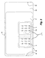
- the about rectangular flexible PPG pad 1 according to a preferred embodiment of the invention illustrated in Figs. 2 and 3 is shown in a disposition for application to the left ankle of a person.
- the hatched line 5 indicates how the pad 1 is aligned with the margo anterior tibiae; a corresponding mark is provided at the rear (outer, when applied to the ankle) face of the pad 1 or the cuff, if a fixed combination of pad 1 and a cuff 50 ( Fig 4 ) is used.
- the pad 1 is applied to the left ankle, the hatched line 5 will abut the skin at the front of the left leg in close proximity of the tibia, with which it is aligned.
- the pad 1 comprises a sheet of soft, flexible silicone material 2, 3, 4, 6 in which a number of first 10, 11, 12, 13, 14, 15 and second 30, 31, 32, 33, 34, 35 light emitting diodes (LED) and photo detectors (PD) 20, 21, 22, 23, 24, 25 are embedded in three rows perpendicular to the hatched line 5, two LED rows and one PD row. Additionally embedded is an AMP board 102 for photodetector signal amplification.
- LED light emitting diodes
- PD photo detectors
- Half of the LEDs in the first or proximal LED row 10, 11, 12, 13, 14, 15 and the LEDs in the second or distal LED row 30, 31, 32, 33, 34, 35 are disposed on either side of line 5.
- LEDs 10, 11, 12 of the first, proximal LED row and LEDs 30, 31, 32 of the second, distal LED row become disposed in proximity of the anterior tibial artery ATA; they are termed ATA LEDs.
- the other half of the LEDs (first or proximal LED row: 13, 14, 15; second or distal LED row: 33, 34, 35) become disposed in proximity of the posterior tibial artery PTA) they are termed PTA LEDs.
- PTA PDs 23, 24, 25 are arranged to the left of line 5, in which disposition they will primarily detect light reflected from the anterior tibial artery area; consequently they are termed ATA PDs 20, 21, 22.
- the other half of photo detectors 20, 21, 22, 23, 24, 25 are arranged to the right of line 5, in which disposition they will primarily detect light reflected from the posterior tibial artery area; consequently they are termed PTA PDs 23, 24, 25.
- the left and right (in relation to line 5) PPDs and photo detectors define left (anterior) and right (posterior) pad sections 2 and 3, respectively, which are separated by an intermediate section 4 that may be of a thinner flexible material such as, for instance, a textile material.
- Sections 2, 3, 4 are surrounded by a narrow circumferential border 6.
- the LEDs and PDs in the left and right portions of a row are disposed in an equidistant manner, the distance between them being about 15 mm.
- the distance of the innermost members (those closest to line 5) in a row is about 50 mm but the distance of the innermost member of a left row from line 5 is substantially shorter (about 15 mm) that the corresponding distance of the innermost member of a left row (about 35 mm); this reflects about the disposition of the corresponding arteries in relation to the front edge (or line 5) of the tibia.
- the distance between rows in a proximal/distal direction is about 20 mm.
- the flexible PPG pad of Figs. 2 and 3 is manufactured in the following way.
- a cast form for the pad body is made from wood.
- the cast material a two-component silicon rubber, Rhodorsil RTV 1556 A and B (Sikema, Sweden; hardness upon curing: 28 ⁇ 3 Shore A) and black pigment, Intensive Black 886,(Uterm, Sweden) is mixed at room temperature in a plastic container, and the mixture is poured into the form. Incorporating black or other pigment light reduces interference by light from outside. Air bubbles are removed by placing the form in a steel container, which is evacuated. The polymer is hardened in an oven.
- the pad body 60 thus produced comprises windows that mirror the LED/PD pattern of the pad 1.
- the LED's and the PD's are accordingly put into the respective windows and fixed by gluing with transparent silicone glue, Glass Silicone Transparent (Dana, Denmark).
- the probe AMP board 102 is placed and fixed by gluing.
- the photo diodes are connected to the probe AMP board 102 by electrical leads disposed on the rear side of the body 60.
- the output lead 8 from the AMP board 102 and the LED power supply lead 7 are inserted into a shielded cable 63, STC-36T-12 (Vishay Measurement Group, Germany).
- a cable connector, HR10A (ELFA, Sweden) is connected to free end of the shielded cable for connection to a PPG board 106 ( Fig. 6 ).
- a sheet of silicone rubber 59 is glued to the rear side of the body 60 to protect the components (PDs, LEDs, probe AMP board, electrical conductors).
- a thin sheet of transparent silicone rubber 58 is glued to the front side of the pad so as to cover it completely.
- the flexible PPG pad 1 thus manufactured is about 15 mm thick. In Fig. 3 its thickness is greatly exaggerated for reasons of clarity. The same is true for the inflatable cuff 57, the lumen of which is indicated by reference number 57. If desired, the flexible PPD pad 1 may be glued or otherwise fixed to the cuff 51 at the inside thereof.
- Suitable LEDs are, for instance, Siemens (Germany) SFH 420 (880 nm).
- Suitable photodetectors are, for instance, Siemens (Germany) BPW34.
- a suitable cuff for blood pressure measurements can be obtained from OMRON Healthcare UK (Henfield, West Wales, UK).
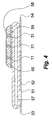
- Fig. 4 illustrates the disposition of the flexible PPG pad of Figs. 2 and 3 in relation to an inflatable cuff 51 of about rectangular shape having a proximal (top) edge 53, a distal (bottom) edge 54, and left 56 and right 55 edges.
- the cuff 51 may be a state-of-the-art cuff used for blood pressure measurements with an inflatable portion 51 and a non-inflatable flap portion 52 provided with a fixation means (not shown) such as Velcro® tape.
- the PPG pad 1 of the invention is disposed close to the distal edge 54 of the cuff. When inflated, the cuff 51 thus restricts arterial blood flow proximally (upstream) of the flexible PPG pad 1 but may additionally restrict blood flow at the application area of the pad.
- EXAMPLE 3 System for measuring systolic ankle blood pressure.
- FIG. 5 An embodiment of the system for determining systolic ankle blood pressure of the invention is schematically illustrated in Fig. 5 .
- the system comprises a flexible PPG pad 1 of the invention and an inflatable cuff 51; both are shown mounted to the ankle of a right leg 8 in which the front edge 9 of the tibia is indicated.
- the flexible PPG pad 1 is positioned between the cuff 51 and the ankle and thus covered by the cuff 50.
- a shielded cable 63 which extends from the PPG pad 1, and a tube 67 for pressurised air, which extends from the cuff 51, are connected with a PPG/cuff pressure control unit 70, which comprises a panel 72 with a screen and operator input means. Power is supplied to the control unit 70 by a power source 108.
- the control unit 70 is in wireless communication with a personal computer 80 in which photodetector signal amplitude and cuff pressure data are analysed and stored.
- Circuitry for assembly for measuring ankle systolic pressure for measuring ankle systolic pressure.
- the circuitry of the system of Fig. 5 for measuring systolic ankle blood pressure measurement is shown in greater detail in Fig. 6 . It comprises at least one light source 100 and at least one photo detector 101 in a flexible PPG pad which is combined with a inflatable cuff C.
- the photo detector 101 is electrically connected to an AMP board 102 in the pad for amplification of the weak detector signal from which it is sent to a PPG board 106 that hierarchically controls the system.
- the PPG board comprises an analog to digital converter.
- the converted LED signal is sent to a PC in which it is analysed and stored.
- Via a pump board 103 the PPG board 106 controls a pump/valve assembly for inflating and deflating the cuff.
- the pump board 103 comprises pressure sensors the signals of which are fed to the PPG board.
- a safety circuit opens a magnetic valve at a selected pressure, which can be adjusted by a potentiometer. Typically the safety limit will be set at about 400 mm Hg.
- the PPG board 106 also controls the light source 101 via an LED driver board 105.
- a bedside operator panel OP comprising a display 110 and a control panel 111 connected to the PPG board 106 allows the operator to carry out the measurement.
- the control panel 111 comprises input means for start/reset of measurement, start/reset of cuff pressure, LED gain, etc.
- the LED signal and other data is presented on a display 110.
- the signal from the PPG board 103 fed to the display is converted in a display board 109 that also comprises latch and driver means for the display. Power from an external power supply 107 is filtered and distributed via a power board 108.
- EXAMPLE 4 PD signal analysis algorithm. Determination of true first systolic peak . The signal analysis used to extract the local PPG peak that corresponds to the pressure in the occlusion cuff just below the systolic pressure (when arterial blood starts to pass the cuff) is performed in three steps:
- Peak selection step Selects the peak that corresponds to the systolic pressure.
- the PPG peak is selected that exhibits the greatest difference in amplitude compared to the peak next in line, and which is followed by a predetermined number of peaks, typically 15-20, depending on sampling time.
- Another method for identifying the first true peak in a PD/cuff pressure diagram is by gating.
- the peak with the largest or second largest amplitude (reference peak) is identified. Peaks smaller than a set fraction of the reference peak are disregarded from. The first peak having an amplitude equal or higher than said fraction is considered to be the first true peak. Gating can be used as such or in combination with other methods.
- EXAMPLE 5 Ankle systolic blood pressure measurement procedure .
- the PPG pad 1 of the invention is positioned at the ankle with the marker corresponding to line 5 in line with the palpable front edge MA of the tibia.
- the cuff 51 is then applied on the pad in a manner that the lower edge of the cuff 51 superimposes the lower edge of the pad 1.
- the person on which the measurement is performed is placed in a supine position on a bed.
- the measurement is started by inflating the cuff 51 while monitoring the PD signals.
- the cuff is inflated above the pressure range at which the PD signals become essentially flat, that is, at which blood ceases to flow in the anterior ATA and posterior PTA tibial arteries.
- the raw PD amplitude signals from the anterior and posterior tibial arteries, respectively, are shown in Fig. 7 in relation to cuff pressure during deflation.
- the corresponding PC-analysed signals are shown in Fig. 8 , in which also the peak corresponding to the first true pulse (heart beat) is identified in each trace.
- the cuff pressure for this peak corresponds to the ankle systolic pressure for the anterior and posterior tibial artery, respectively.
- EXAMPLE 6 PPD pad systolic ankle blood pressure measurement evaluation - Non-invasive measurements. For comparison with the standard Doppler technique, 20 healthy volunteers (24 - 55 of age, 15 men) were examined. All subjects were placed supine on a bed at room temperature. The measurements were performed at the right ankle after five minutes of rest. Along with the PPG recordings, CW Doppler pressure measurements in the arteria dorsalis pedis and posterior tibial arteries were performed simultaneously using an 8-MHz handheld Doppler (MD-8, Sonotech GMBH, Schwaben, Germany). The systolic pressure was read on the aneroid sphygmomanometer at the closest 2mm Hg. Four consecutive measurements were performed, two in each ankle artery.
- MD-8 8-MHz handheld Doppler
- the PPG signals were stored on the PC hard disc for later analysis. During the procedure, the PPG-derived pressures were not available to the examiner. The influence of incorrect probe positioning was tested in 18 of the subjects. Measurements were made with the cuff and pad rotated 2 cm medially and laterally from the correct position, respectively. Two measurements were performed in each position, one in each ankle artery, using the same procedure as above. A PPD pad with the LED/photo detector configuration of Figs. 2 and 3 was used.
- the simultaneous CW Doppler measurements were carried out with an aneroid sphygmomanometer (Maxi-Stabil 3, Welch Allyn, New York, USA) connected to the pressure regulator unit.
- EXAMPLE 7 PPG pad ankle systolic pressure measurement evaluation - invasive measurements. Ten neurosurgical or thoracic patients at the intensive care unit (40 - 75 years old, three males) with an arterial line put in for clinical monitoring purposes were included. None had a diagnosis of peripheral arterial disease; all had palpable foot pulses. A 1.1 x 45 mm cannula (BD, UK) was inserted in the arteria dorsalis pedis on the dorsum pedis. The cannula was fixed and connected to tubings that included devices for calibration against heart level, and a damping device. The line was connected to a pressure-monitoring device (HP M 1006A/B pressure module and HP Viridia monitor, Hewlett Packard, USA).
- EXAMPLE 8 Simultanous measurement of ankle and arm systolic blood pressure.
- Ankle systolic pressure measurements with the pad of the invention were carried out in combination with the simultaneous measurement of systolic blood pressure in the arm to obtain the so-called Ankle Brachial Index (ABI).
- An ABI of >0.95 indicates a healthy state.
- Ankle pad measurements of the invention substituted the standard Doppler ultrasound technique.
- a pad of a design similar to that of the ankle pad of the invention but simplified, there being no need to discern between pressures in various brachial arteries, can be used for brachial systolic blood pressure measurement.
- the measurement of ABI can be accomplished with both pads connected to a single control unit corresponding to control unit 70 of Fig. 5 .
- the computer 80 compares the measured ankle and brachial pressures for calculation of ABI.
Description
- The present invention relates to a means for measuring systolic blood pressure in the ankle.
- The determination or monitoring of systolic blood pressure (SBP) is important for the appropriate control of patients with unstable haemodynamics. Invasive measurement by arterial catheters provides correct results but should be avoided, if possible, due to the risk thrombotic events and septicaemia, the formation of haematomae, and cost. Non-invasive methods for measuring or monitoring SBP utilise inflatable (pneumatic) cuffs by which the arterial blood flow in an arm, leg, or finger can be stopped. In the auscultatory or auditory method of Korotkov the pneumatic cuff is wrapped around an upper arm. By inflating the cuff the blood flow in the brachial artery is stopped. A stethoscope is placed over this artery distally off the cuff. On progressive deflation pulsating sounds are detected. SBP corresponds to the manometrically measured pressure in the cuff at which the pulsating sounds can be first heard while the diastolic blood pressure (DBP) corresponds to the lower pressure in the cuff at which the they disappear. Instead of the auscultatory method the Doppler effect of an ultrasound beach backscattered from moving red blood cells can be used for the measurement and monitoring of SBP. An ultrasound transceiver is placed over the artery distally of the cuff. The onset of arterial blood flow during deflation of the cuff corresponds to SBP, and the Doppler effect generated by the moving red blood cells gives rise to a sound signal in the audible range. Appropriate sites for measuring SBP by the Doppler method are the brachial and radial arteries of the arms and the tibial arteries of the legs. During monitoring the probe must be kept at a correct angle and a sufficient pressure against the skin. A third method for measuring SBP known in the art is the oscillometric method. The oscillating signal emanates from the small, pulse-dependent component in the cuff pneumatic pressure during standard (that is, auscultatory) blood pressure monitoring. The oscillating signal is caused by the mechanical coupling of the blood pressure in the artery which oscillates between SBP and consecutively lower pressure due to ongoing deflation of the cuff. The oscillometric signal is considered to have its maximum amplitude at a mean arterial blood pressure (MAP). From this signal oscillometric devices on the market calculate SBP and DBP using different algorithms most often kept secret by the respective manufacturer. SBP determined by oscillatory techniques is in good agreement with invasively obtained SPB (E O'Brien et al., Brit. Med. J. 322:531-536).
- Determination of the systolic blood pressure in the ankle (ASP), and the calculation of the ankle-brachial blood pressure index (ABPI) are important elements in the investigation of leg ischemia. There is increasing interest in these parameters due to the association between a reduced ABPI and generalised arteriosclerotic disease.
- Various methods for determining ASP are known in the art. In a standard method, a hand-held continuous-wave pen Doppler device of a frequency of about 8 to 10 MHz and a standard pneumatic cuff for temporarily restricting blood flow are used. Studies of this method (J Stoffers et al., Scand. J. Prim. Health Care 1991;9:109-114; K W Johnston et al., J. Vasc. Surg. 1987;6:147-151; F G R Fowkes et al., J. Epidem. Comm. Health 1988;42:128-133) indicated a variability in ABPI of 10% to 22% in a laboratory setting (95% confidence limitis for single measurement vs. mean of repeated measurements). In clinical practice the variability can be expected to be even higher due to intrinsic problems associated with this technique (S A Ray et al., Br. J. Surg. 1994;81:188-190; C M Fisher et al., J. Vasc. Surg. 1996;24:871-875). The examiner has to localise individual ankle arteries with the probe and keep it in the same position and angle during cuff inflation and deflation. Other devices for ASP measurement, such as automatic oscillometric pressure recorders (M Adiseshiah et al., Ann. Royal Coll. Surg. Engl. 1987;69:271-273; B Y Lee et al., J Vasc. Surg. 1996;23:116-122) are potentially less examiner-dependent. While giving comparable results to the Doppler method in healthy individuals, the oscillometric method is considered unreliable in arterial occlusive disease (B Jönsson et al., Clin. Physiol. 2001;21(2):155-163).
- Photopletysmography (PPG) is a further technique by which SBP can be measured. A small area of the skin is illuminated by a light source directly or indirectly, such as via an optical fibre. The radiation, in particular red or infrared radiation, is diffusely scattered in the tissue and blood. A portion is scattered back and can be detected by a photo detector placed adjacent to the illuminated area (reflection mode). With thin tissues, such as on fingertips, it is also possible to detect the scatted light on a skin surface opposite to the illuminated area (transmission mode). PPG is used for non-invasively monitoring pulse rate, respiratory rate, tissue blood perfusion, arterial oxygen saturation, and blood pressure (K Yamakoshi et al., Med. Biol. Eng. Comput. 1982;20:307-313; R Chawla et al., Anesth. Analg. 1992; 74: 196-200; M Langbaum et al, J. Pediatr. 1994;125:591-595;
U.S. Patent No. 6,120,459 ; The article by S. Tanaka and K. Yamakoshi, Med. & Biol. Eng. & Comput., 1996, vol. 34, p. 441-447, describes a disc-type cuff that may be attached to a user's head using a belt, for measuring blood pressure in the superficial temporal artery. The cuff includes a PPG sensor comprising two pairs of light emitting diodes and photo detectors, said pairs being disposed in parallel, the detectors being adapted for detecting light emitted by the respective diode into tissue and reflected from there, the cuff further comprising conductor means for providing power to the light emitting diodes from a power source and conducting means for putting the detectors in communication with electronic equipment for detector signal analysis. -
US 6 533 729 B1 discloses a device for measuring SBP based on PPG. The sensor is mounted on a flexible band for application to the wrist, and comprises a plurality of light emitting diodes and photo detectors. - >
- It is an object of the invention to provide a device for a non-invasive method for measuring systolic blood pressure in the ankle, which is simpler than methods known in the art.
- It is another object of the invention to provide a device for a non-invasive method for measuring systolic blood pressure in the ankle, which is more reliable than methods known in the art.
- Still further objects of the invention will become apparent from the following short description of the invention and a number of preferred embodiments thereof illustrated in a drawing, and the appended claims.
- The invention relates to a PPG pad as detailed in
claim 1. - The PPG pad of the present invention is useful in a method for measuring systolic blood pressure in the ankle of a subject, comprising
- providing an assembly including an ankle cuff, a flexible measuring pad ("PPG pad") comprising at least two pairs of light emitting diodes and photo detectors, and an electronic control unit in communication with the pad, the pad being optionally fixed at the cuff;
- positioning the pad or, if the pad is fixed at the cuff, the combination of pad and cuff in contact with the skin of the ankle region of the subject so as to dispose one pair in proximity of the anterior tibial artery and substantially parallel with it and the other pair in proximity of the posterior tibial artery and substantially parallel with it and, if the pad and cuff are separate, positioning the cuff around the pad that is in contact with the skin of the ankle region;
- inflating the cuff to a pressure sufficient for stopping blood flow through the anterior and posterior tibial arteries;
- deflating the cuff while making the diodes emit light;
- recording the light reflected from the tissue by the photo detectors during deflation;
- recording the cuff pressure during deflation;
- analysing the recorded light signal to identify the cuff pressure at which of blood flow in the anterior and/or posterior tibial arteries is resumed.
- It is preferred to position the pad or the combination of pad and cuff on the ankle in a manner so as to dispose the photo detectors downstream of the light emitting diodes in respect of the blood flow in said arteries.
- It is also preferred to position the pad in respect of the cuff so as to avoid compression of ankle tissue distally of the pad.
- According to the present invention there is provided a flexible pad for measuring systolic ankle blood pressure (also termed "PPG pad"), comprising at least two pairs of light emitting diodes and photo detectors disposed in parallel, the detectors being adapted for detecting light emitted by the respective diode into tissue and reflected from there, the pad further comprising conductor means, preferably shielded, for providing power to the light emitting diodes from a power source and conducting means for putting the detectors in communication with electronic equipment for detector signal analysis. It is preferred for the pad to comprise a means for detector signal amplification, such as an AMP board. It is also preferred for the pad to be about rectangular in shape, its short sides extending in a proximal/distal direction when mounted. The pad is of a size that allows it to be wrapped around at least half of the circumference of the ankle of an adult person. It is also preferred for the SPMP to be divided into two sections of about rectangular shape, the line of division being parallel to the short sides, the sections being termed anterior tibial artery section and posterior tibial artery section. It is though within the ambit of the invention to position the light emitting diodes and/or the photo detectors elsewhere in/on the pad or separate of the pad while providing for light and/or optical signal communication by optical fibers extending from the positions at which the LED's and PD's are intended to be disposed according to the invention to the actual disposition of the LED's and PD's.
- According to one preferred aspect of the invention, the light emitting diodes and the photo detectors of the pairs are disposed in a rectangular pattern or in a rectangular network pattern in the pad.
- According to a second preferred aspect of the invention the at least two pairs of light emitting diodes and photodetectors are disposed in separate sections of the pad, each section comprising at least one such pair. In a pad with two such pairs, it is preferred for the distance between the light emitting diode and the photodetector in each pair to be smaller than the distance between the light emitting diodes and the photodetectors. In a pad with at least three such pairs, it is preferred for the distance between the light emitting diode and the photodetector in each pair to be smaller than the distance between the light emitting diodes and the photodetectors of the two adjacent pairs that pertain to separate sections.
- According to a third preferred aspect of the invention, the pad or the combination of pair and cuff is provided with a mark indicating its correct position in regard of the anterior margo tibiae.
- According to a fourth preferred aspect of the invention each light emitting diode and photodetector pair comprises an additional light emitting diode, preferably disposed in a linear manner on the cuff and with the photodetector positioned in-between the light emitting diodes.
- According to a fifth preferred aspect, at least three pairs, each preferably comprising an additional photodetector disposed in the manner of the fourth preferred aspect, are arranged in each section of the pad.
- According to a sixth preferred aspect a combination of the pad of the invention and an inflatable ankle cuff is provided. Preferably, the pad is fixed to the cuff, either permanently or, more preferred, releasingly, such as by Velcro® means.
- According to the present invention is also provided a system for measuring systolic blood pressure in the ankle of a subject, comprising the measuring pad of the invention, an ankle cuff that may be fixed to the pad or be separate, pump means for inflating and deflating the cuff, gauge means for recording the pressure in the cuff, electronic means for amplification of photodetector signals, computing means for analysing the amplified signal, and power supply means.
- The invention will now be explained in greater detail by reference to the drawings.
-
-
Fig. 1 is a rough sketch of a transverse section through a leg at its plane of smallest circumference at which the PPG pad is mounted; -
Fig. 2 is a preferred embodiment of the PPG pad of the invention, in a top view of its application face; -
Fig. 3 is a transverse section along line A-A through the PPG pad ofFig. 2 in combination with a inflatable cuff; -
Fig. 4 is the PPG pad ofFig. 2 , disposed on the cuff, in the same view as inFig. 2 ; -
Fig. 5 is a schematic view of a preferred embodiment of the system of the invention for measuring ankle systolic blood pressure; -
Fig. 6 is a scheme illustrating the circuitry of the embodiment ofFig. 5 ; -
Fig. 7 is a diagram showing raw PPG pad sensor signal amplitude v. cuff pressure traces for the anterior tibial artery and the posterior tibial artery during deflation obtained with the system ofFig. 5 ; -
Fig. 8 is a diagram showing the amplitude v. cuff pressure traces refined by computer analysis of the corresponding traces ofFig. 7 , the identification of the first true pulsatile signal in the anterior tibial artery (ATA 1) and the posterior tibial artery (PTA 1), and the corresponding cuff pressure; -
Fig. 9 is a graph comparing systolic ankle pressure data obtained by the method disclosed herein and from state-of-the-art CW Doppler measurements; -
Fig. 10 is a graph illustrating the effect of incorrect positioning of the PPG pad of the invention on PPG measurements of systolic blood pressure in the ankle; and -
Fig. 11 is a graph comparing systolic blood pressure in the ankle obtained by the method disclosed herein and by an invasive method. - EXAMPLE 1. Anatomic considerations.
Fig. 1 illustrates schematically a transverse section through a right leg at its plane of smallest circumference at which the PPG pad is mounted, with tibia T, fibula F, anterior tibial artery A, posterior tibial artery PTA, peroneal artery PA, and skin S shown. - Leg circumference at its most narrow ankle section was measured in 84 individuals (Table 1; age 18-85 years, median 67 years; 52 men, 32 women; 66 patients, 18 healthy volunteers; both legs).
Table 1. Leg circumference and distance of arteries and their cutaneous projections in an ankle cross sectional plane Range Mean SD Leg circumference (161 legs in 84 subjects*) , mm Distance artery/cutaneous proj. 170 - 265 218 20 (both legs in 20 subjects), mm - Anterior tibial a. 9 - 26 15 4 - Posterior tibial a. 8 - 24 15 4 - Peroneal a. 13 - 36 22 5 *) Legs with ankle edema (n=7) excluded - In 20 of the legs the distance between the skin surface and the major ankle arteries, dATA for the anterior tibial artery, dPTA for the posterior tibial artery, dPA for the peroneal artery, was measured by colour-coded Duplex ultrasound (Table 1; ATL HDI5000 with an L 7-4 linear probe, Philips, Netherlands). In addition, the distance dcf between the cutaneous (skin designated S in
Fig. 1 ) projections of the anterior ATA and posterior PTA tibial arteries in the cross sectional plane was measured in the right leg of 34 other subjects of the study group (19 patients, 15 healthy volunteers) by 8 MHz or 10 MHz hand-held Doppler ultrasound probes (Table 1). The width of the tibial bone in the same plane, measured as the distance d MM-MA , between the margo anterior MA, the easily palpable frontal edge of the tibia, and the margo medialis MM, the lateral (inward) edge of the tibia, as calculated from nuclear magnetic resonance tomography (MR) images of one leg in seven healthy volunteers (26-52 years; five men, two women). A mean of 25 mm (SD 2, range 23-28 mm was obtained for d MM-MA . - EXAMPLE 2. PPG pad design. Based on the anatomical findings, the features of a probe for measuring systolic blood pressure at the ankle were set to allow a variation of more than two standard deviations from the mean values in ankle circumference and in the distance between the arteries. The thickness of the tibial bone and its relation to the arteries, based on the MR scans, were also taken into account in setting the distance between the two channels. By the design of the probe, the considerably deeper located peroneal artery was assumed to be essentially beyond the detection range.
- The positioning of the probe pays regard to the asymmetry of the arteries relative to the easily palpable frontal edge of the tibia. A marker on the probe (or one outside the cuff if a fixed probe/cuff combination is used) is positioned in line with this anatomical landmark. Since the anatomy of the right ankle is a reflection of the left and the probe prototype is asymmetrical, it has to be rotated 180° when right and left legs are examined, respectively.
- The about rectangular
flexible PPG pad 1 according to a preferred embodiment of the invention illustrated inFigs. 2 and3 is shown in a disposition for application to the left ankle of a person. The hatchedline 5 indicates how thepad 1 is aligned with the margo anterior tibiae; a corresponding mark is provided at the rear (outer, when applied to the ankle) face of thepad 1 or the cuff, if a fixed combination ofpad 1 and a cuff 50 (Fig 4 ) is used. When thepad 1 is applied to the left ankle, the hatchedline 5 will abut the skin at the front of the left leg in close proximity of the tibia, with which it is aligned. Thepad 1 comprises a sheet of soft,flexible silicone material line 5, two LED rows and one PD row. Additionally embedded is anAMP board 102 for photodetector signal amplification. When applied to the subject the portion of thepad 1 on the top ofFig. 2 becomes the proximal portion; correspondingly the portion at the bottom becomes the distal portion. Half of the LEDs in the first orproximal LED row distal LED row line 5. ThusLEDs LEDs photo detectors line 5, in which disposition they will primarily detect light reflected from the anterior tibial artery area; consequently they are termedATA PDs photo detectors line 5, in which disposition they will primarily detect light reflected from the posterior tibial artery area; consequently they are termedPTA PDs pad sections Sections circumferential border 6. The LEDs and PDs in the left and right portions of a row are disposed in an equidistant manner, the distance between them being about 15 mm. The distance of the innermost members (those closest to line 5) in a row is about 50 mm but the distance of the innermost member of a left row fromline 5 is substantially shorter (about 15 mm) that the corresponding distance of the innermost member of a left row (about 35 mm); this reflects about the disposition of the corresponding arteries in relation to the front edge (or line 5) of the tibia. The distance between rows in a proximal/distal direction is about 20 mm. - The flexible PPG pad of
Figs. 2 and3 is manufactured in the following way. A cast form for the pad body is made from wood. The cast material, a two-component silicon rubber, Rhodorsil RTV 1556 A and B (Sikema, Sweden; hardness upon curing: 28±3 Shore A) and black pigment, Intensive Black 886,(Uterm, Sweden) is mixed at room temperature in a plastic container, and the mixture is poured into the form. Incorporating black or other pigment light reduces interference by light from outside. Air bubbles are removed by placing the form in a steel container, which is evacuated. The polymer is hardened in an oven. Thepad body 60 thus produced comprises windows that mirror the LED/PD pattern of thepad 1. The LED's and the PD's are accordingly put into the respective windows and fixed by gluing with transparent silicone glue, Glass Silicone Transparent (Dana, Denmark). In an additional window theprobe AMP board 102 is placed and fixed by gluing. The photo diodes are connected to theprobe AMP board 102 by electrical leads disposed on the rear side of thebody 60. The output lead 8 from theAMP board 102 and the LEDpower supply lead 7 are inserted into a shieldedcable 63, STC-36T-12 (Vishay Measurement Group, Germany). A cable connector, HR10A (ELFA, Sweden) is connected to free end of the shielded cable for connection to a PPG board 106 (Fig. 6 ). After control of optical and electrical functions, a sheet ofsilicone rubber 59 is glued to the rear side of thebody 60 to protect the components (PDs, LEDs, probe AMP board, electrical conductors). A thin sheet oftransparent silicone rubber 58 is glued to the front side of the pad so as to cover it completely. Theflexible PPG pad 1 thus manufactured is about 15 mm thick. InFig. 3 its thickness is greatly exaggerated for reasons of clarity. The same is true for theinflatable cuff 57, the lumen of which is indicated byreference number 57. If desired, theflexible PPD pad 1 may be glued or otherwise fixed to thecuff 51 at the inside thereof. Suitable LEDs are, for instance, Siemens (Germany) SFH 420 (880 nm). Suitable photodetectors are, for instance, Siemens (Germany) BPW34. A suitable cuff for blood pressure measurements can be obtained from OMRON Healthcare UK (Henfield, West Sussex, UK). -
Fig. 4 illustrates the disposition of the flexible PPG pad ofFigs. 2 and3 in relation to aninflatable cuff 51 of about rectangular shape having a proximal (top)edge 53, a distal (bottom)edge 54, and left 56 and right 55 edges. Thecuff 51 may be a state-of-the-art cuff used for blood pressure measurements with aninflatable portion 51 and anon-inflatable flap portion 52 provided with a fixation means (not shown) such as Velcro® tape. ThePPG pad 1 of the invention is disposed close to thedistal edge 54 of the cuff. When inflated, thecuff 51 thus restricts arterial blood flow proximally (upstream) of theflexible PPG pad 1 but may additionally restrict blood flow at the application area of the pad. - An embodiment of the system for determining systolic ankle blood pressure of the invention is schematically illustrated in
Fig. 5 . The system comprises aflexible PPG pad 1 of the invention and aninflatable cuff 51; both are shown mounted to the ankle of aright leg 8 in which thefront edge 9 of the tibia is indicated. Theflexible PPG pad 1 is positioned between thecuff 51 and the ankle and thus covered by the cuff 50. A shieldedcable 63, which extends from thePPG pad 1, and atube 67 for pressurised air, which extends from thecuff 51, are connected with a PPG/cuffpressure control unit 70, which comprises apanel 72 with a screen and operator input means. Power is supplied to thecontrol unit 70 by apower source 108. Thecontrol unit 70 is in wireless communication with apersonal computer 80 in which photodetector signal amplitude and cuff pressure data are analysed and stored. - The circuitry of the system of
Fig. 5 for measuring systolic ankle blood pressure measurement is shown in greater detail inFig. 6 . It comprises at least onelight source 100 and at least onephoto detector 101 in a flexible PPG pad which is combined with a inflatable cuff C. Thephoto detector 101 is electrically connected to anAMP board 102 in the pad for amplification of the weak detector signal from which it is sent to aPPG board 106 that hierarchically controls the system. The PPG board comprises an analog to digital converter. The converted LED signal is sent to a PC in which it is analysed and stored. Via apump board 103 thePPG board 106 controls a pump/valve assembly for inflating and deflating the cuff. Thepump board 103 comprises pressure sensors the signals of which are fed to the PPG board. A safety circuit opens a magnetic valve at a selected pressure, which can be adjusted by a potentiometer. Typically the safety limit will be set at about 400 mm Hg. ThePPG board 106 also controls thelight source 101 via anLED driver board 105. A bedside operator panel OP comprising adisplay 110 and acontrol panel 111 connected to thePPG board 106 allows the operator to carry out the measurement. Thecontrol panel 111 comprises input means for start/reset of measurement, start/reset of cuff pressure, LED gain, etc. The LED signal and other data is presented on adisplay 110. The signal from thePPG board 103 fed to the display is converted in adisplay board 109 that also comprises latch and driver means for the display. Power from anexternal power supply 107 is filtered and distributed via apower board 108. - EXAMPLE 4. PD signal analysis algorithm. Determination of true first systolic peak. The signal analysis used to extract the local PPG peak that corresponds to the pressure in the occlusion cuff just below the systolic pressure (when arterial blood starts to pass the cuff) is performed in three steps:
- a) The information reduction step is constituted by a differentiating filter (a simple first order differentiating convolution kernel), followed by a 10th order band pass Butterworth filter with cut frequencies at 4Hz and 9Hz applied to the signal in order to retain only the pulsatile features of the signal.
- b) Peak extraction step. Extracts PPG signals corresponding to true heart beats. PPG peaks that correspond to true beats are determined by analysis of the amplitude of the signal appearing within intervals determined by, in part, the assumption that a reasonable heart rate at rest does not exceed 100 beats per min and, in part, by the most frequently occurring amplitude peak distance, i.e., the heart rate. The amplitude of the signal is determined by using a 16th order Hilpert transformer filter.
- The Hilbert transformer is a filter that approximates the discrete Hilbert transform

of a signal
which is an integral part of the analytic signal - The analytical signal is in turn used to derive the amplitude of the signal

as the instantaneous amplitude of
- c) Peak selection step. Selects the peak that corresponds to the systolic pressure. The PPG peak is selected that exhibits the greatest difference in amplitude compared to the peak next in line, and which is followed by a predetermined number of peaks, typically 15-20, depending on sampling time.
- It is, of course, also possible to visually determine the ankle systolic pressure by identifying in the PD v. cuff pressure trace the first peak in a row of peaks of increasing amplitude and about equal spacing.
- Another method for identifying the first true peak in a PD/cuff pressure diagram is by gating. The peak with the largest or second largest amplitude (reference peak) is identified. Peaks smaller than a set fraction of the reference peak are disregarded from. The first peak having an amplitude equal or higher than said fraction is considered to be the first true peak. Gating can be used as such or in combination with other methods.
- EXAMPLE 5. Ankle systolic blood pressure measurement procedure. The
PPG pad 1 of the invention is positioned at the ankle with the marker corresponding toline 5 in line with the palpable front edge MA of the tibia. Thecuff 51 is then applied on the pad in a manner that the lower edge of thecuff 51 superimposes the lower edge of thepad 1. The person on which the measurement is performed is placed in a supine position on a bed. The measurement is started by inflating thecuff 51 while monitoring the PD signals. The cuff is inflated above the pressure range at which the PD signals become essentially flat, that is, at which blood ceases to flow in the anterior ATA and posterior PTA tibial arteries. Monitoring is continued during the entire procedure of inflation and deflation of thecuff 51, which lasts about 120 seconds (cuff deflation rate approx. 3 mm Hg/s). On release of the pressure in the cuff the signals from the anterior and posterior tibial arteries, respectively, appear consecutively (Fig. 8 ) or about at the same time, depending on the condition of the particular patient. - The raw PD amplitude signals from the anterior and posterior tibial arteries, respectively, are shown in
Fig. 7 in relation to cuff pressure during deflation. The corresponding PC-analysed signals are shown inFig. 8 , in which also the peak corresponding to the first true pulse (heart beat) is identified in each trace. The cuff pressure for this peak corresponds to the ankle systolic pressure for the anterior and posterior tibial artery, respectively. - EXAMPLE 6. PPD pad systolic ankle blood pressure measurement evaluation - Non-invasive measurements. For comparison with the standard Doppler technique, 20 healthy volunteers (24 - 55 of age, 15 men) were examined. All subjects were placed supine on a bed at room temperature. The measurements were performed at the right ankle after five minutes of rest. Along with the PPG recordings, CW Doppler pressure measurements in the arteria dorsalis pedis and posterior tibial arteries were performed simultaneously using an 8-MHz handheld Doppler (MD-8, Sonotech GMBH, Schwaben, Germany). The systolic pressure was read on the aneroid sphygmomanometer at the closest 2mm Hg. Four consecutive measurements were performed, two in each ankle artery. The PPG signals were stored on the PC hard disc for later analysis. During the procedure, the PPG-derived pressures were not available to the examiner. The influence of incorrect probe positioning was tested in 18 of the subjects. Measurements were made with the cuff and pad rotated 2 cm medially and laterally from the correct position, respectively. Two measurements were performed in each position, one in each ankle artery, using the same procedure as above. A PPD pad with the LED/photo detector configuration of
Figs. 2 and3 was used. - The simultaneous CW Doppler measurements were carried out with an aneroid sphygmomanometer (Maxi-
Stabil 3, Welch Allyn, New York, USA) connected to the pressure regulator unit. - Visual analysis of the reappearance of PPG pulsations during cuff exsufflation was possible in all 80 measurements, despite numerous movement artefacts and/or noise. The results are shown in
Fig. 9 (mean of two measurements in each position). Rotating the combination of cuff and pad two cm laterally from the central, predetermined "correct" position produced a mean difference between CW Doppler and PPG results in the anterior tibial artery of 10.1 mm Hg (SD 11.5). This compared to -4.9 mm Hg (SD 8.4) with the "correct" position (n=17 (one measurement excluded due to technical errors), p<0.001). In the posterior tibial artery, the mean differences were 13.6 mm Hg (SD 13.1) and 0.2 mm Hg (SD 7.6) respectively (n=18, p<0.001). A 2 cm medial rotation did not alter the mean error significantly, but the standard deviations increased (mean differences CW Doppler - PPG -3.6 (SD 13.3) and 3.4 (SD 11.1) mm Hg for the anterior and posterior arteries, respectively) (Fig. 10 ). - EXAMPLE 7. PPG pad ankle systolic pressure measurement evaluation - invasive measurements. Ten neurosurgical or thoracic patients at the intensive care unit (40 - 75 years old, three males) with an arterial line put in for clinical monitoring purposes were included. None had a diagnosis of peripheral arterial disease; all had palpable foot pulses. A 1.1 x 45 mm cannula (BD, UK) was inserted in the arteria dorsalis pedis on the dorsum pedis. The cannula was fixed and connected to tubings that included devices for calibration against heart level, and a damping device. The line was connected to a pressure-monitoring device (HP M 1006A/B pressure module and HP Viridia monitor, Hewlett Packard, USA). The pressure curves were carefully checked for artefacts (flushing technique), and a damping device was used when necessary to avoid under-damping ("ringing"). For practical reasons, PPG recordings were performed in the contralateral leg. Doppler systolic pressures in the arteria dorsalis pedis arteries of right and left leg were examined. Only subjects with a pressure difference not exceeding 5 mm Hg between legs were accepted. The intra-arterial systolic pressure from the arterial line was recorded during exsufflaton of the cuff. A minimum of six measurements were performed in each patient. In comparison with systolic ankle pressure measured intra-arterially in the arteria dorsalis pedis, PPG (by visual examination) underestimated systolic pressure in the contralateral anterior tibial artery by 4.5 mm Hg (SD 11.2), (
Fig. 11 ). - Statistics. Continuous data are presented as their means and standard deviations (SD). 95% confidence intervals were calculated for mean differences. Pearson correlation coefficient (r) were calculated where appropriate. Comparisons were performed using Student's t-test for paired samples. P-values of less than 5% were considered statistically significant. All calculations were performed using SPSS for Windows version 11.0 (SPSS Inc., USA).
- EXAMPLE 8. Simultanous measurement of ankle and arm systolic blood pressure. Ankle systolic pressure measurements with the pad of the invention were carried out in combination with the simultaneous measurement of systolic blood pressure in the arm to obtain the so-called Ankle Brachial Index (ABI). An ABI of >0.95 indicates a healthy state. Ankle pad measurements of the invention substituted the standard Doppler ultrasound technique. A pad of a design similar to that of the ankle pad of the invention but simplified, there being no need to discern between pressures in various brachial arteries, can be used for brachial systolic blood pressure measurement. The measurement of ABI can be accomplished with both pads connected to a single control unit corresponding to control
unit 70 ofFig. 5 . Thecomputer 80 compares the measured ankle and brachial pressures for calculation of ABI.
Claims (16)
- A photoplethysmographic flexible pad (1) for measuring systolic ankle blood pressure wherein the pad is attachable to the ankle by means of an inflatable cuff, and the pad comprises two or more pairs of light emitting diodes and photo detectors, said pairs being disposed in parallel, the detectors being adapted for detecting light emitted by the respective diode into tissue and reflected from there, the pad further comprising conductor means (63) for providing power to the light emitting diodes from a power source and for putting the detectors in communication with electronic equipment for detector signal analysis, wherein the pad is of a length allowing it to extend around at least half of the circumference of the ankle of an adult person, and wherein the disposition of the light emitting diodes and the photodetectors allows separate detection of light reflected from the anterior tibial artery and from the posterior tibial artery.
- The pad of claim 1 comprising a means for detector signal amplification.
- The pad of claim 2, wherein the detector signal amplification means comprises an AMP board (102).
- The pad of any of claims 1 to 3 of about rectangular shape, its short sides being designed to extend in a proximal/distal direction when mounted on the leg of a patient.
- The pad of any of claims 1 or 4 comprising two sections of about rectangular shape, the line of division (5) being parallel to the short sides and configured for disposition along the margo anterior tibiae in a mounted position.
- The pad of claim 5, wherein each section comprises one or more pairs of light emitting diodes and one or more pairs of photodetectors.
- The pad of claim 1, wherein the distance between the light emitting diode and the photodetector in a pair is smaller than the distance between light emitting diodes and photodetectors in different pairs.
- The pad of claim 1 or 6, wherein said disposition includes that of the free ends of optical fibers extending from said light emitting diodes and/or photodetectors.
- The pad of any of claims 1 to 8, wherein the light emitting diodes and the photo detectors and/or the corresponding free ends of the optical fibers are disposed in rectangular pattern or a rectangular network pattern.
- The pad of any of claims 1 to 9, comprising six pairs of light emitting diodes and photodetectors.
- The combination of the pad of any of claims 1 to 10 and an inflatable ankle cuff (51).
- The combination of claim 11, wherein the pad is fixed to the cuff.
- The combination of claim 12, wherein the pad is releasingly fixed to the cuff.
- A system for measuring systolic blood pressure in the ankle of a subject, comprising the measuring pad of any of claims 1 to 10, an ankle cuff fixed to the pad or separate of it, pump means for inflating and deflating the cuff, gauge means for recording the pressure in the cuff, electronic means for amplification of photodetector signals, computing means for analysing the amplified signal, and power supply means.
- A system for determining the Ankle Brachial Index (ABI) of a subject, comprising the system of claim 14, means configured for determining brachial systolic blood pressure, and means configured for calculating ABI.
- The system of claim 15, wherein the means for determining brachial systolic pressure include a brachial measuring pad comprising at least one pair of light emitting diode and photodetector, a brachial cuff, pump means for inflating and deflating the brachial cuff, gauge means for recording the pressure in the brachial cuff, electronic means for amplification of photodetector signals from the brachial measuring pad, and computing means configured for analysing the amplified signal from the brachial cuff.
Applications Claiming Priority (2)
| Application Number | Priority Date | Filing Date | Title |
|---|---|---|---|
| SE0402673A SE0402673D0 (en) | 2004-11-04 | 2004-11-04 | Methods and means for measuring systolic blood pressure in the ankle |
| PCT/SE2005/001657 WO2006049571A1 (en) | 2004-11-04 | 2005-11-04 | Method and means for measuring systolic blood pressure in the ankle |
Publications (3)
| Publication Number | Publication Date |
|---|---|
| EP2112902A1 EP2112902A1 (en) | 2009-11-04 |
| EP2112902A4 EP2112902A4 (en) | 2011-01-05 |
| EP2112902B1 true EP2112902B1 (en) | 2014-05-21 |
Family
ID=33488151
Family Applications (1)
| Application Number | Title | Priority Date | Filing Date |
|---|---|---|---|
| EP05798789.3A Not-in-force EP2112902B1 (en) | 2004-11-04 | 2005-11-04 | Pad for measuring systolic blood pressure in the ankle using ppg |
Country Status (5)
| Country | Link |
|---|---|
| US (1) | US20080269619A1 (en) |
| EP (1) | EP2112902B1 (en) |
| ES (1) | ES2492916T3 (en) |
| SE (1) | SE0402673D0 (en) |
| WO (1) | WO2006049571A1 (en) |
Families Citing this family (13)
| Publication number | Priority date | Publication date | Assignee | Title |
|---|---|---|---|---|
| GB0603564D0 (en) | 2006-02-23 | 2006-04-05 | Huntleigh Technology Plc | Automatic ankle brachial pressure index system |
| WO2010003134A2 (en) | 2008-07-03 | 2010-01-07 | Masimo Laboratories, Inc. | Protrusion, heat sink, and shielding for improving spectroscopic measurement of blood constituents |
| US8630691B2 (en) | 2008-08-04 | 2014-01-14 | Cercacor Laboratories, Inc. | Multi-stream sensor front ends for noninvasive measurement of blood constituents |
| JP5228750B2 (en) * | 2008-09-26 | 2013-07-03 | オムロンヘルスケア株式会社 | Blood pressure information measuring device |
| US20100292586A1 (en) * | 2009-05-13 | 2010-11-18 | Rooke Thom W | Wireless automatic ankle-brachial index (AABI) measurement system |
| FI20105335A0 (en) * | 2010-03-31 | 2010-03-31 | Polar Electro Oy | Heart rate detection |
| CN101828908A (en) * | 2010-05-10 | 2010-09-15 | 上海理工大学 | Cuff-free portable device for monitoring human physiological parameters and method |
| US20130303923A1 (en) * | 2012-05-11 | 2013-11-14 | Biomedix, Inc. | System and method for vascular testing |
| EP2939593A1 (en) | 2014-05-02 | 2015-11-04 | Lindberg, Lars-Göran | Device and system for determining physiological parameters from the sternum bone |
| US20160007862A1 (en) * | 2014-07-14 | 2016-01-14 | Mediatek Inc. | Method for collecting personal health data and personal health device utilizing the same |
| CN104783771B (en) * | 2015-05-08 | 2017-10-27 | 青岛大学附属医院 | The postoperative strong and weak monitoring device of artery of lower extremity beating of femoral artery puncture |
| WO2017199174A1 (en) * | 2016-05-20 | 2017-11-23 | Christian Medical College | Non-invasive system and method for measuring blood pressure variability |
| WO2021258049A1 (en) * | 2020-06-19 | 2021-12-23 | Mgi, Llc | Optical ankle-brachial index and blood pressure measurement system and method |
Family Cites Families (13)
| Publication number | Priority date | Publication date | Assignee | Title |
|---|---|---|---|---|
| US4726382A (en) * | 1986-09-17 | 1988-02-23 | The Boc Group, Inc. | Inflatable finger cuff |
| US4821734A (en) * | 1987-04-21 | 1989-04-18 | Nihon Seimitsu Sokki Co., Ltd. | Sphygmomanometer |
| US4825872A (en) * | 1988-08-05 | 1989-05-02 | Critikon, Inc. | Finger sensor for pulse oximetry system |
| US5873821A (en) * | 1992-05-18 | 1999-02-23 | Non-Invasive Technology, Inc. | Lateralization spectrophotometer |
| JP3529886B2 (en) * | 1995-04-19 | 2004-05-24 | 株式会社エー・アンド・デイ | Blood pressure cuff |
| WO2000017615A2 (en) * | 1998-09-23 | 2000-03-30 | Keith Bridger | Physiological sensing device |
| US20030195774A1 (en) * | 1999-08-30 | 2003-10-16 | Abbo Fred E. | Medical practice management system |
| JP3363847B2 (en) * | 1999-09-06 | 2003-01-08 | 日本コーリン株式会社 | Blood pressure measurement device |
| AU2001221391A1 (en) * | 2000-01-26 | 2001-08-07 | Vsm Medtech Ltd. | Continuous blood pressure monitoring method and apparatus |
| US6816266B2 (en) * | 2000-02-08 | 2004-11-09 | Deepak Varshneya | Fiber optic interferometric vital sign monitor for use in magnetic resonance imaging, confined care facilities and in-hospital |
| US6533729B1 (en) * | 2000-05-10 | 2003-03-18 | Motorola Inc. | Optical noninvasive blood pressure sensor and method |
| JP3563364B2 (en) * | 2001-04-11 | 2004-09-08 | コーリンメディカルテクノロジー株式会社 | Venous thromboembolism prevention device |
| US20050010121A1 (en) * | 2003-07-09 | 2005-01-13 | Ross William Payne | System and method for detecting and analyzing electrocardiological signals of a laboratory animal |
-
2004
- 2004-11-04 SE SE0402673A patent/SE0402673D0/en unknown
-
2005
- 2005-11-04 WO PCT/SE2005/001657 patent/WO2006049571A1/en active Application Filing
- 2005-11-04 EP EP05798789.3A patent/EP2112902B1/en not_active Not-in-force
- 2005-11-04 ES ES05798789.3T patent/ES2492916T3/en active Active
- 2005-11-04 US US11/719,061 patent/US20080269619A1/en not_active Abandoned
Also Published As
| Publication number | Publication date |
|---|---|
| SE0402673D0 (en) | 2004-11-04 |
| EP2112902A4 (en) | 2011-01-05 |
| US20080269619A1 (en) | 2008-10-30 |
| WO2006049571A1 (en) | 2006-05-11 |
| ES2492916T3 (en) | 2014-09-10 |
| EP2112902A1 (en) | 2009-11-04 |
Similar Documents
| Publication | Publication Date | Title |
|---|---|---|
| EP2112902B1 (en) | Pad for measuring systolic blood pressure in the ankle using ppg | |
| CA2492027C (en) | Body surface probe, apparatus and method for non-invasively detecting medical conditions | |
| EP0723417B1 (en) | Finger cot oximetric probe | |
| US20170311824A1 (en) | Non-invasively monitoring blood parameters | |
| US7544168B2 (en) | Measuring systolic blood pressure by photoplethysmography | |
| US4494550A (en) | Measuring apparatus for the non-invasive detection of venous and arterial blood flow and drainage disorders | |
| US20210030372A1 (en) | Methods to estimate the blood pressure and the arterial stiffness based on photoplethysmographic (ppg) signals | |
| JP4903980B2 (en) | Pulse oximeter and operation method thereof | |
| JP3940150B2 (en) | Caffres electronic blood pressure monitor | |
| US5337744A (en) | Low noise finger cot probe | |
| US20140142434A1 (en) | System and method of measurement of systolic blood pressure | |
| US9700217B2 (en) | Method and apparatus for noninvasive blood pressure measurement using pulse oximetry | |
| JP2008532680A (en) | Improved in vivo blood spectroscopy | |
| WO1991011137A1 (en) | Enhanced arterial oxygen saturation determination and arterial blood pressure monitoring | |
| US11504014B2 (en) | Apparatus and methods for measuring blood pressure and other vital signs via a finger | |
| Wallace et al. | Comparison of blood pressure measurement by Doppler and by pulse oximetry techniques | |
| Jönsson et al. | A new probe for ankle systolic pressure measurement using photoplethysmography (PPG) | |
| Mohler et al. | Use of a pulse oximeter for determination of systolic blood pressure in a helicopter air ambulance | |
| JP2022539462A (en) | Apparatus, system and method for evaluating internal organs | |
| Magee | Physiological monitoring: principles and non-invasive monitoring |
Legal Events
| Date | Code | Title | Description |
|---|---|---|---|
| PUAI | Public reference made under article 153(3) epc to a published international application that has entered the european phase |
Free format text: ORIGINAL CODE: 0009012 |
|
| 17P | Request for examination filed |
Effective date: 20070602 |
|
| AK | Designated contracting states |
Kind code of ref document: A1 Designated state(s): AT BE BG CH CY CZ DE DK EE ES FI FR GB GR HU IE IS IT LI LT LU LV MC NL PL PT RO SE SI SK TR |
|
| A4 | Supplementary search report drawn up and despatched |
Effective date: 20101202 |
|
| REG | Reference to a national code |
Ref country code: DE Ref legal event code: R079 Ref document number: 602005043731 Country of ref document: DE Free format text: PREVIOUS MAIN CLASS: A61B0005022000 Ipc: A61B0005022500 |
|
| GRAP | Despatch of communication of intention to grant a patent |
Free format text: ORIGINAL CODE: EPIDOSNIGR1 |
|
| RIC1 | Information provided on ipc code assigned before grant |
Ipc: A61B 5/021 20060101ALI20131128BHEP Ipc: A61B 5/0225 20060101AFI20131128BHEP Ipc: G01L 17/00 20060101ALI20131128BHEP Ipc: G01L 11/02 20060101ALI20131128BHEP |
|
| INTG | Intention to grant announced |
Effective date: 20131218 |
|
| GRAS | Grant fee paid |
Free format text: ORIGINAL CODE: EPIDOSNIGR3 |
|
| GRAA | (expected) grant |
Free format text: ORIGINAL CODE: 0009210 |
|
| AK | Designated contracting states |
Kind code of ref document: B1 Designated state(s): AT BE BG CH CY CZ DE DK EE ES FI FR GB GR HU IE IS IT LI LT LU LV MC NL PL PT RO SE SI SK TR |
|
| REG | Reference to a national code |
Ref country code: GB Ref legal event code: FG4D |
|
| REG | Reference to a national code |
Ref country code: CH Ref legal event code: EP |
|
| REG | Reference to a national code |
Ref country code: AT Ref legal event code: REF Ref document number: 669172 Country of ref document: AT Kind code of ref document: T Effective date: 20140615 |
|
| REG | Reference to a national code |
Ref country code: IE Ref legal event code: FG4D |
|
| REG | Reference to a national code |
Ref country code: DE Ref legal event code: R096 Ref document number: 602005043731 Country of ref document: DE Effective date: 20140710 |
|
| REG | Reference to a national code |
Ref country code: SE Ref legal event code: TRGR |
|
| REG | Reference to a national code |
Ref country code: NL Ref legal event code: T3 |
|
| REG | Reference to a national code |
Ref country code: LT Ref legal event code: MG4D |
|
| PG25 | Lapsed in a contracting state [announced via postgrant information from national office to epo] |
Ref country code: FI Free format text: LAPSE BECAUSE OF FAILURE TO SUBMIT A TRANSLATION OF THE DESCRIPTION OR TO PAY THE FEE WITHIN THE PRESCRIBED TIME-LIMIT Effective date: 20140521 Ref country code: LT Free format text: LAPSE BECAUSE OF FAILURE TO SUBMIT A TRANSLATION OF THE DESCRIPTION OR TO PAY THE FEE WITHIN THE PRESCRIBED TIME-LIMIT Effective date: 20140521 Ref country code: GR Free format text: LAPSE BECAUSE OF FAILURE TO SUBMIT A TRANSLATION OF THE DESCRIPTION OR TO PAY THE FEE WITHIN THE PRESCRIBED TIME-LIMIT Effective date: 20140822 Ref country code: IS Free format text: LAPSE BECAUSE OF FAILURE TO SUBMIT A TRANSLATION OF THE DESCRIPTION OR TO PAY THE FEE WITHIN THE PRESCRIBED TIME-LIMIT Effective date: 20140921 |
|
| PG25 | Lapsed in a contracting state [announced via postgrant information from national office to epo] |
Ref country code: LV Free format text: LAPSE BECAUSE OF FAILURE TO SUBMIT A TRANSLATION OF THE DESCRIPTION OR TO PAY THE FEE WITHIN THE PRESCRIBED TIME-LIMIT Effective date: 20140521 Ref country code: PL Free format text: LAPSE BECAUSE OF FAILURE TO SUBMIT A TRANSLATION OF THE DESCRIPTION OR TO PAY THE FEE WITHIN THE PRESCRIBED TIME-LIMIT Effective date: 20140521 |
|
| PG25 | Lapsed in a contracting state [announced via postgrant information from national office to epo] |
Ref country code: PT Free format text: LAPSE BECAUSE OF FAILURE TO SUBMIT A TRANSLATION OF THE DESCRIPTION OR TO PAY THE FEE WITHIN THE PRESCRIBED TIME-LIMIT Effective date: 20140922 |
|
| PG25 | Lapsed in a contracting state [announced via postgrant information from national office to epo] |
Ref country code: EE Free format text: LAPSE BECAUSE OF FAILURE TO SUBMIT A TRANSLATION OF THE DESCRIPTION OR TO PAY THE FEE WITHIN THE PRESCRIBED TIME-LIMIT Effective date: 20140521 Ref country code: BE Free format text: LAPSE BECAUSE OF FAILURE TO SUBMIT A TRANSLATION OF THE DESCRIPTION OR TO PAY THE FEE WITHIN THE PRESCRIBED TIME-LIMIT Effective date: 20140521 Ref country code: RO Free format text: LAPSE BECAUSE OF FAILURE TO SUBMIT A TRANSLATION OF THE DESCRIPTION OR TO PAY THE FEE WITHIN THE PRESCRIBED TIME-LIMIT Effective date: 20140521 Ref country code: DK Free format text: LAPSE BECAUSE OF FAILURE TO SUBMIT A TRANSLATION OF THE DESCRIPTION OR TO PAY THE FEE WITHIN THE PRESCRIBED TIME-LIMIT Effective date: 20140521 Ref country code: CZ Free format text: LAPSE BECAUSE OF FAILURE TO SUBMIT A TRANSLATION OF THE DESCRIPTION OR TO PAY THE FEE WITHIN THE PRESCRIBED TIME-LIMIT Effective date: 20140521 Ref country code: SK Free format text: LAPSE BECAUSE OF FAILURE TO SUBMIT A TRANSLATION OF THE DESCRIPTION OR TO PAY THE FEE WITHIN THE PRESCRIBED TIME-LIMIT Effective date: 20140521 |
|
| REG | Reference to a national code |
Ref country code: DE Ref legal event code: R097 Ref document number: 602005043731 Country of ref document: DE |
|
| PLBE | No opposition filed within time limit |
Free format text: ORIGINAL CODE: 0009261 |
|
| STAA | Information on the status of an ep patent application or granted ep patent |
Free format text: STATUS: NO OPPOSITION FILED WITHIN TIME LIMIT |
|
| 26N | No opposition filed |
Effective date: 20150224 |
|
| PG25 | Lapsed in a contracting state [announced via postgrant information from national office to epo] |
Ref country code: IT Free format text: LAPSE BECAUSE OF FAILURE TO SUBMIT A TRANSLATION OF THE DESCRIPTION OR TO PAY THE FEE WITHIN THE PRESCRIBED TIME-LIMIT Effective date: 20140521 |
|
| REG | Reference to a national code |
Ref country code: DE Ref legal event code: R097 Ref document number: 602005043731 Country of ref document: DE Effective date: 20150224 |
|
| PG25 | Lapsed in a contracting state [announced via postgrant information from national office to epo] |
Ref country code: LU Free format text: LAPSE BECAUSE OF FAILURE TO SUBMIT A TRANSLATION OF THE DESCRIPTION OR TO PAY THE FEE WITHIN THE PRESCRIBED TIME-LIMIT Effective date: 20141104 Ref country code: MC Free format text: LAPSE BECAUSE OF FAILURE TO SUBMIT A TRANSLATION OF THE DESCRIPTION OR TO PAY THE FEE WITHIN THE PRESCRIBED TIME-LIMIT Effective date: 20140521 |
|
| REG | Reference to a national code |
Ref country code: CH Ref legal event code: PL |
|
| PG25 | Lapsed in a contracting state [announced via postgrant information from national office to epo] |
Ref country code: CH Free format text: LAPSE BECAUSE OF NON-PAYMENT OF DUE FEES Effective date: 20141130 Ref country code: SI Free format text: LAPSE BECAUSE OF FAILURE TO SUBMIT A TRANSLATION OF THE DESCRIPTION OR TO PAY THE FEE WITHIN THE PRESCRIBED TIME-LIMIT Effective date: 20140521 Ref country code: LI Free format text: LAPSE BECAUSE OF NON-PAYMENT OF DUE FEES Effective date: 20141130 |
|
| REG | Reference to a national code |
Ref country code: IE Ref legal event code: MM4A |
|
| PG25 | Lapsed in a contracting state [announced via postgrant information from national office to epo] |
Ref country code: IE Free format text: LAPSE BECAUSE OF NON-PAYMENT OF DUE FEES Effective date: 20141104 |
|
| REG | Reference to a national code |
Ref country code: FR Ref legal event code: PLFP Year of fee payment: 11 |
|
| PG25 | Lapsed in a contracting state [announced via postgrant information from national office to epo] |
Ref country code: BG Free format text: LAPSE BECAUSE OF FAILURE TO SUBMIT A TRANSLATION OF THE DESCRIPTION OR TO PAY THE FEE WITHIN THE PRESCRIBED TIME-LIMIT Effective date: 20140521 |
|
| PG25 | Lapsed in a contracting state [announced via postgrant information from national office to epo] |
Ref country code: CY Free format text: LAPSE BECAUSE OF FAILURE TO SUBMIT A TRANSLATION OF THE DESCRIPTION OR TO PAY THE FEE WITHIN THE PRESCRIBED TIME-LIMIT Effective date: 20140521 |
|
| PG25 | Lapsed in a contracting state [announced via postgrant information from national office to epo] |
Ref country code: TR Free format text: LAPSE BECAUSE OF FAILURE TO SUBMIT A TRANSLATION OF THE DESCRIPTION OR TO PAY THE FEE WITHIN THE PRESCRIBED TIME-LIMIT Effective date: 20140521 Ref country code: HU Free format text: LAPSE BECAUSE OF FAILURE TO SUBMIT A TRANSLATION OF THE DESCRIPTION OR TO PAY THE FEE WITHIN THE PRESCRIBED TIME-LIMIT; INVALID AB INITIO Effective date: 20051104 |
|
| REG | Reference to a national code |
Ref country code: FR Ref legal event code: PLFP Year of fee payment: 12 |
|
| PGFP | Annual fee paid to national office [announced via postgrant information from national office to epo] |
Ref country code: NL Payment date: 20161013 Year of fee payment: 12 Ref country code: GB Payment date: 20161121 Year of fee payment: 12 Ref country code: FR Payment date: 20161130 Year of fee payment: 12 Ref country code: DE Payment date: 20161115 Year of fee payment: 12 |
|
| PGFP | Annual fee paid to national office [announced via postgrant information from national office to epo] |
Ref country code: ES Payment date: 20161130 Year of fee payment: 12 Ref country code: AT Payment date: 20161020 Year of fee payment: 12 Ref country code: BE Payment date: 20161125 Year of fee payment: 12 Ref country code: SE Payment date: 20161118 Year of fee payment: 12 |
|
| REG | Reference to a national code |
Ref country code: DE Ref legal event code: R119 Ref document number: 602005043731 Country of ref document: DE |
|
| REG | Reference to a national code |
Ref country code: SE Ref legal event code: EUG |
|
| REG | Reference to a national code |
Ref country code: NL Ref legal event code: MM Effective date: 20171201 |
|
| REG | Reference to a national code |
Ref country code: AT Ref legal event code: MM01 Ref document number: 669172 Country of ref document: AT Kind code of ref document: T Effective date: 20171104 |
|
| GBPC | Gb: european patent ceased through non-payment of renewal fee |
Effective date: 20171104 |
|
| PG25 | Lapsed in a contracting state [announced via postgrant information from national office to epo] |
Ref country code: SE Free format text: LAPSE BECAUSE OF NON-PAYMENT OF DUE FEES Effective date: 20171105 Ref country code: AT Free format text: LAPSE BECAUSE OF NON-PAYMENT OF DUE FEES Effective date: 20171104 |
|
| REG | Reference to a national code |
Ref country code: FR Ref legal event code: ST Effective date: 20180731 Ref country code: BE Ref legal event code: FP Effective date: 20140818 Ref country code: BE Ref legal event code: MM Effective date: 20171130 |
|
| PG25 | Lapsed in a contracting state [announced via postgrant information from national office to epo] |
Ref country code: FR Free format text: LAPSE BECAUSE OF NON-PAYMENT OF DUE FEES Effective date: 20171130 Ref country code: DE Free format text: LAPSE BECAUSE OF NON-PAYMENT OF DUE FEES Effective date: 20180602 Ref country code: NL Free format text: LAPSE BECAUSE OF NON-PAYMENT OF DUE FEES Effective date: 20171201 |
|
| PG25 | Lapsed in a contracting state [announced via postgrant information from national office to epo] |
Ref country code: BE Free format text: LAPSE BECAUSE OF NON-PAYMENT OF DUE FEES Effective date: 20171130 Ref country code: GB Free format text: LAPSE BECAUSE OF NON-PAYMENT OF DUE FEES Effective date: 20171104 |
|
| REG | Reference to a national code |
Ref country code: ES Ref legal event code: FD2A Effective date: 20181226 |
|
| PG25 | Lapsed in a contracting state [announced via postgrant information from national office to epo] |
Ref country code: ES Free format text: LAPSE BECAUSE OF NON-PAYMENT OF DUE FEES Effective date: 20171105 |