EP2104008A1 - Single-body regulating organ and method for manufacturing same - Google Patents
Single-body regulating organ and method for manufacturing same Download PDFInfo
- Publication number
- EP2104008A1 EP2104008A1 EP08153101A EP08153101A EP2104008A1 EP 2104008 A1 EP2104008 A1 EP 2104008A1 EP 08153101 A EP08153101 A EP 08153101A EP 08153101 A EP08153101 A EP 08153101A EP 2104008 A1 EP2104008 A1 EP 2104008A1
- Authority
- EP
- European Patent Office
- Prior art keywords
- balance
- silicon
- layer
- regulating member
- pattern
- Prior art date
- Legal status (The legal status is an assumption and is not a legal conclusion. Google has not performed a legal analysis and makes no representation as to the accuracy of the status listed.)
- Withdrawn
Links
Images


Classifications
-
- G—PHYSICS
- G04—HOROLOGY
- G04D—APPARATUS OR TOOLS SPECIALLY DESIGNED FOR MAKING OR MAINTAINING CLOCKS OR WATCHES
- G04D3/00—Watchmakers' or watch-repairers' machines or tools for working materials
- G04D3/0002—Watchmakers' or watch-repairers' machines or tools for working materials for mechanical working other than with a lathe
- G04D3/0035—Watchmakers' or watch-repairers' machines or tools for working materials for mechanical working other than with a lathe for components of the regulating mechanism
- G04D3/0038—Watchmakers' or watch-repairers' machines or tools for working materials for mechanical working other than with a lathe for components of the regulating mechanism for balances
-
- G—PHYSICS
- G04—HOROLOGY
- G04B—MECHANICALLY-DRIVEN CLOCKS OR WATCHES; MECHANICAL PARTS OF CLOCKS OR WATCHES IN GENERAL; TIME PIECES USING THE POSITION OF THE SUN, MOON OR STARS
- G04B17/00—Mechanisms for stabilising frequency
- G04B17/04—Oscillators acting by spring tension
- G04B17/06—Oscillators with hairsprings, e.g. balance
- G04B17/063—Balance construction
-
- G—PHYSICS
- G04—HOROLOGY
- G04B—MECHANICALLY-DRIVEN CLOCKS OR WATCHES; MECHANICAL PARTS OF CLOCKS OR WATCHES IN GENERAL; TIME PIECES USING THE POSITION OF THE SUN, MOON OR STARS
- G04B17/00—Mechanisms for stabilising frequency
- G04B17/04—Oscillators acting by spring tension
- G04B17/06—Oscillators with hairsprings, e.g. balance
- G04B17/066—Manufacture of the spiral spring
Definitions
- the invention relates to a regulating member and its method of manufacture and, more particularly, to a regulating member of the spring-balance type.
- the regulating member of a timepiece generally comprises an inertia flywheel called a balance wheel and a resonator called a spiral. These pieces are decisive for the running quality of the timepiece. Indeed, they regulate the movement, that is to say that they control the frequency of the movement.
- the balance and the spiral are different in nature which makes the focus of the regulating organ, which includes the own fabrications pendulum and spiral and their assembly substantially resonance, extremely complex.
- the balance and the hairspring have each been manufactured in various materials, in particular in order to limit the influence of a change in temperature without the resonance assembly difficulties disappearing.
- the object of the present invention is to overcome all or part of the aforementioned drawbacks by proposing a monobloc regulator which remains insensitive to temperature changes and which is obtained by means of a manufacturing process which minimizes the difficulties of assembly.
- the invention relates to a monobloc regulating member comprising a balance cooperating with a spiral made in a layer of silicon-based material and comprising a spiral spring coaxially mounted on a ferrule, the ferrule comprising an extension part. protruding from said spiral spring and which is made in a second layer of silicon-based material characterized in that the extension portion of the shell of the spiral is fixed on the balance.
- the invention also relates to a timepiece characterized in that it comprises a one-piece regulating member according to one of the preceding variants.
- the invention relates to a generally annotated method 1 for manufacturing a regulating member 41, 41 ', 41 "for a timepiece movement.
- Figures 1 to 9 process 1 comprises successive steps for forming at least one type of monobloc member (51 ", 41) which can be integrally formed of silicon-based materials.
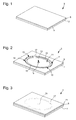
- the first step 100 is to provide a substrate 3 of the type silicon on insulator (also known by the acronym SOI).
- the substrate 3 comprises an upper layer 5 and a lower layer 7 each composed of silicon. Between the upper 5 and lower 7 layers, may extend an intermediate layer 9 composed of silicon dioxide (SiO 2 ).
- the substrate 3 is chosen so that the height of the lower layer 7 corresponds to the height of a portion of the final regulator member 41, 41 ', 41 ". have a thickness sufficient to withstand the forces induced by the method 1.
- a thickness may be for example between 300 and 400 microns.
- the upper layer 5 is used as spacing means with respect to the lower layer 7. Therefore, the height of the upper layer 5 will be adapted according to the configuration of the regulating member 41, 41 ', 41 " According to said configuration, the thickness of the upper layer 5 can thus oscillate, for example, between 10 and 200 ⁇ m.
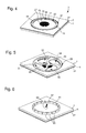
- cavities 10, 11, 12, 13, 14 and 15 are selectively etched, for example by a deep reactive ion etching process (also known as DRIE), in the upper layer 5 of silicon-based material .
- these cavities 10, 11, 12, 13, 14 and 15 form two patterns 17, 19 defining the inner and outer contours of silicon parts of the regulating member 41, 41 ', 41 ".
- the patterns 17 and 19 are substantially in the form of coaxial cylinders with circular section, the pattern 17 having a larger diameter than that of the pattern 19.
- the etching on the upper layer 5 leaves all freedom on the geometry of the patterns 17 and 19.
- the patterns 17 and 19 are not necessarily circular but, for example, elliptical or have a non-circular inner diameter.
- bridges of material 18 are left in order to maintain the substrate 3 the regulator member 41, 41 ', 41 "during its manufacturing.
- a third step 102 as visible in figure 3 an additional layer 21 of silicon-based material is added to the substrate 3.
- the additional layer 21 is fixed on the upper layer 5 by means of a fusion welding of silicon (also known by the acronym SFB) .
- Step 102 advantageously allows the upper layer 5 to be covered by bonding with a very strong adhesion, in particular the upper faces of the patterns 17 and 19 on the lower face of the additional layer 21.
- the additional layer 21 may, for example, comprise a thickness between 100 and 150 ⁇ m.
- cavities 20, 22 and 24 are selectively etched, for example, by a method of the DRIE type similar to that of step 101, into the additional layer 21 of silicon-based material. These cavities 20, 22 and 24 make it possible to form three patterns 23, 25 and 27 defining the inner and outer contours of silicon parts of the regulating member 41, 41 ', 41 ".
- the patterns 23 and 25 are substantially in the form of coaxial cylinders with a circular section and, the pattern 27, substantially in the form of a spiral.
- the etching on the additional layer 21 leaves complete freedom on the geometry of the patterns 23, 25 and 27.
- the patterns 23 and 25 are not necessarily circular but, for example, elliptical or have a non-circular inner diameter. It is the same, in particular, for the inner diameters 10 and 24 which are not necessarily circular but, for example, polygonal which could make it possible to improve the transmission of rotational force with an axis 49 of corresponding form.
- each diameter 10, 24 may not be of identical shape.
- the pattern 23 made in the additional layer 21 is of similar shape and substantially perpendicular to the pattern 19 made in the upper layer 5.
- the cavities 10 and 24 respectively forming the inside diameter of the patterns 19 and 23 communicate together and are substantially one above the other.
- the units 23 and 19 form the shell 55, 55 ', 55 "of the regulating member 41, 41', 41" which extends in height on the layers 5 and 21.
- the pattern 25 made in the additional layer 21 is of similar shape and substantially perpendicular to the pattern 17 made in the upper layer 5.
- the patterns 25 and 17 form part of the serge 47, 47 ', 47 "of the balance 43, 43', 43" of the regulating member 41, 41 ', 41 "which extends in height in particular on the layers 5 and 21.
- the material bridges 18 are not reproduced and that the cavity 22 in the additional layer 21 forms a continuous ring unlike the cavities 12, 13, 14 and 15 which open out under it to the figure 4 .
- the patterns 23 and 27 are etched at the same time and form a single piece in the additional layer 21.
- the units 23 and 27 form the spiral spring 53, 53 ', 53 "and the upper part of the shell 55, 55', 55" of the regulating member 41, 41 ', 41 ".
- external curve of the pattern 27 shown in FIG. figure 4 is open. This last characteristic associated with the spacing with respect to the lower layer 7 produced by the pattern 19 makes it possible to embellish said external curve by means of a raquet.
- the etching on the additional layer 21 leaves all freedom on the geometry of the pattern 27.
- the pattern 27 may not include an external curve open but, for example, have on the end of the outer curve a bead adapted to serve as a fixed attachment point, that is to say without the need for raquetry.
- the pattern 27 may also comprise an internal turn comprising a Grossmann type curve to improve its concentricity of development as explained in the document EP 1 612 627 incorporated by reference into the present description
- the patterns 23 and 27 etched in the additional layer 21 are only connected by the underside of the pattern 23, with a very strong adhesion, above the etched pattern 19 of the upper layer. 5 (the pattern 19 is itself connected, with a very strong adhesion, to the lower layer 7).
- the patterns 23 and 27 are therefore no longer in direct contact with the additional layer 21.
- the pattern 25 is no longer in direct contact with the additional layer 21 but only connected, with a very strong adhesion, to the pattern 17 etched of the upper layer 5.
- the method 1 may comprise a fifth step 104 which consists in oxidizing at least the pattern 27, that is to say the spiral spring 53, 53 ', 53 “of the regulating member 41, 41', 41 “in order to adjust its thermo-elastic coefficient but also to make it mechanically more resistant.
- a fifth step 104 which consists in oxidizing at least the pattern 27, that is to say the spiral spring 53, 53 ', 53 “of the regulating member 41, 41', 41 "in order to adjust its thermo-elastic coefficient but also to make it mechanically more resistant.
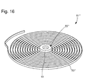
- the method 1 advantageously allows to produce only the spiral 51 "'as visible in FIG. figure 16 .
- one of the advantages of the method 1 is to be able to adapt the height of the pattern 19 of the shell 55, 55 ', 55 “, 55”' protruding spiral spring 53, 53 ', 53 “, 53”' directly by choosing the thickness of the upper layer 5.
- step 103 or 104 it is sufficient to stop the process 1 at step 103 or 104 by providing the intermediate step of forming bridges of material.
- Such bridges of matter may in particular be formed either on the pattern 19 during step 101 or on the pattern 27 at the end, for example, of the last turn in step 103.
- the penultimate step of method 1 could then consist of removing the lower layer 7, for example, by etching and / or mechanical.
- step 106 the hairspring 51 "'thus obtained would be released.
- the method 1 may comprise three embodiments A, B and C as illustrated in FIG. the figure 9 .
- each of the three embodiments A, B and C ends with the same final step 106 of freeing the substrate 3 the regulating member 41, 41 ', 41 "manufactured.
- the release step 106 can then be simply performed by providing a force to the regulating member 41, 41 ', 41 "capable of breaking its material bridges 18.
- This effort can, for example, be generated manually by a operator or by machining.
- cavities 26, 28, 29, 30, 31 and 32 are selectively etched, for example, by a method of the DRIE type similar to that of steps 101 and 103, in the lower layer 7 of silicon-based material. These cavities 26, 28, 29, 30, 31 and 32 make it possible to form a pattern 34 defining the inner and outer contours of a silicon part of the regulating member 41.
- the pattern 34 is substantially in the form of four-armed rim.
- the etching on the lower layer 7 leaves all freedom on the geometry of the pattern 34.
- the number and the geometry of the arms can be different just as the rim is not necessarily circular but for example, elliptical.
- the arms may be slender to allow their axial deformation and / or radial in case of shock transmitted to the regulating member.
- part of the pattern 34 made in the lower layer 7 is of similar shape and substantially perpendicular to the patterns 17 and 25 made respectively in the upper and additional layers 5 and 21.
- the pattern 34 forms, with the patterns 17 and 25, the balance 43 of the regulating member 41, the serge 47 therefore extends in height over all of the layers 5, 7 and 21.
- the cavity 26 of the pattern 34 is substantially in extension of the cavities 10 and 24 forming the inner diameter of the patterns 19 and 23.
- the successive cavities 24, 10 and 26 thus form a suitable internal diameter. receiving the balance shaft 49 of the regulating member 41.
- a monoblock regulator 41 integrally formed of silicon-based materials is obtained, as visible in FIGS. Figures 10 and 11 . It is therefore clear that there is no longer any problem of assembly because it is directly achieved during the manufacture of the regulating member 41.
- the latter comprises a rocker 43 whose hub 45 is connected firstly radially to the serge 47 by four arms 40, 42, 44 and 46 and, on the other hand, axially to the hairspring 51, the hairspring 51 comprises a hairspring 53 and a shell 55.
- the serge 47 is formed by the peripheral ring of the pattern 34 of the lower layer 7 but also by the patterns 17 and 25 of the respective upper and additional layers 21.
- the ferrule 55 is formed by the pattern 23 of the additional layer 21 and the pattern 19 of the upper layer 5.
- this pattern 19 is used as spacing means between the spiral 51 and the balance 43 to be able to for example, punctuating the spiral spring 53 with a raquet.
- the pattern 19 is also useful as a guide means of the hairspring 51 by increasing the height of the shell 55.
- the etching on the additional layer 21 leaves complete freedom on the geometry of the spiral spring 53.
- the spiral spring 53 may not have an open external curve but, for example, comprise on the end of the outer curve a bead adapted to serve as a fixed attachment point, that is to say without the need for raquetry.
- the regulating member 41 is adapted to receive a balance shaft 49 through the cavities 24, 10 and 26.
- the regulating member 41 being in one piece, it is not necessary to fix the axis balance 49 to the ferrule 55 and balance 43 but only to one of them.
- the balance shaft 49 is fixed on the inner diameter 26 of the balance 43, for example by means of elastic means 48 etched in the hub 45 of silicon.
- elastic means 48 may, for example, take the form of those disclosed in the Figures 10A to 10E patent EP 1 655 642 or those disclosed in the Figures 1, 3 and 5 patent EP 1 584 994 which patents are incorporated by reference in the present description.
- the cavities 24 and 10 have sections of larger dimensions than that of the cavity 26 to prevent the balance shaft 49 is in bold contact with the ferrule 55.
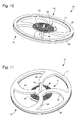
- the method 1 comprises, after the step 103 or 104, a sixth step 107, as visible in FIG. figure 6 , consisting in implementing a process of the LIGA type (well-known acronym from the German "Röntgenlithographie, Galvanoformung &Abformung").
- LIGA well-known acronym from the German "Röntgenlithographie, Galvanoformung &Abformung”
- Such a process comprises a succession of steps making it possible to electrodeposit in a particular form a metal on the lower layer 7 of the substrate 3 with the aid of a photostructured resin.
- the deposited metal may be, for example, gold or nickel or one of their alloys.
- step 107 may consist of depositing a castellated ring 61 and / or a cylinder 63.
- the ring 61 comprises a series of pads 65 substantially in a circular arc and is intended to advantageously increase the mass of the future balance 43 '.
- a first characteristic of the invention therefore consists in increasing the mass of the rocker arm 43 'with the aid of metal obtained by electroplating in order to increase the inertia of the future rocker arm 43'.
- the metal deposited on the lower layer 7 has a spacing between each pad 65 able to compensate for the thermal expansions of the ring 23.
- the cylinder 63 is intended to receive, advantageously, by driving a balance shaft 49.
- another disadvantage of silicon lies in its very weak areas of elastic and plastic which makes it very brittle.
- Another feature of the invention is thus to achieve the clamping of the balance shaft 49 not against the silicon-based material of the balance 43 'but on the inner diameter 67 of the metal cylinder 63 electrodeposited during step 107
- the cylinder 63 obtained by electroplating leaves full freedom as to its geometry. So, in particular, the internal diameter 67 is not necessarily circular but, for example, polygonal which could improve the transmission of rotational force with an axis 49 of corresponding shape.
- a seventh step 108 similar to the step 105 visible at the figure 5 cavities are selectively etched, for example, by a method of the DRIE type, in the lower layer 7 of silicon-based material. These cavities make it possible to form a balance pattern similar to the pattern 34 of embodiment A.
- the pattern obtained can be substantially in the form of four-armed rim.
- the etching on the lower layer 7 leaves all freedom on the geometry of the pattern 34.
- the number and the geometry of the arms can be different just as the rim is not necessarily circular but for example, elliptical.
- the arms may be slender to allow their axial deformation and / or radial in case of shock transmitted to the regulating member.
- a rocker pattern portion made in the lower layer 7 is of similar shape and substantially vertically above the patterns 17 and 25 made respectively during the steps 101 and 103 in the upper and additional layers 5 and 21.
- the balance pattern forms, with the patterns 17 and 25 and the metal parts 61 and / or 63, the balance 43 'of the regulating member 41' whose serge 47 'therefore extends in height over all the layers 5, 7 and 21 and metal parts 61 and / or 63.
- the successive cavities thus form an inside diameter adapted to receive the balance shaft 49 of the regulating member 41 '.
- this seventh step 108 it is understood that the rocker pattern engraved in the lower layer 7 is only connected, with a very strong adhesion to the patterns 17 and 19 of the upper layer 5 etched in step 101.
- the pendulum pattern is no longer in direct contact with the lower layer 7.
- a one-piece regulator 41 'formed of silicon-based materials with one or two parts 61, 63 is obtained.
- metal as visible to Figures 12 and 13 . It is therefore understood that there is no longer a problem of assembly because it is directly achieved during the manufacture of the regulating member 41 '.
- the latter comprises a rocker 43 'whose hub 45' is connected on the one hand radially to the serge 47 'by four arms 40', 42 ', 44' and 46 'and, on the other hand, axially to the spiral 51' , the spiral 51 'comprises a spiral spring 53' and a ferrule 55 '.
- the serge 47 ' is formed by the peripheral ring of the balance pattern of the lower layer 7 but also by the patterns 25 and 17 of the respective upper and additional layers 21 and, optionally, the metal part 61.
- the shell 55 ' is formed by the pattern 23 of the additional layer 21 and the pattern 19 of the upper layer 5.
- this pattern 19 is used as spacing means between the spiral 51' and the balance 43 'so as to pit the spiral spring 53' with a raquetetterie.
- the pattern 19 is also useful as a guiding means of the hairspring 51 'by increasing the height of the shell 55'.
- the etching on the additional layer 21 leaves complete freedom on the geometry of the spiral spring 53 '.
- the spiral spring 53 ' may not have an open external curve but, for example, have on the end of the outer curve a bead suitable for serving as a fixed attachment point, that is to say say without the need for snowshoeing.
- the regulating member 41 ' is able to receive a balance shaft 49 in its inside diameter.
- the regulating member 41 ' being integral, it is not necessary to fix the balance shaft 49 to the shell 55 'and the balance 43' but only to one of the two.
- the balance shaft 49 is preferably fixed to the inner diameter 67 of the metal part 63, for example by driving.
- the cavities 24 and 10 have sections of larger dimensions than the inner diameter 67 of the metal portion 63 to prevent the balance shaft 49 is in bold contact with the ferrule 55 '.
- the balance shaft 49 thus receives force from the regulating member 41 'only, preferably, via the metal portion 63 of the hub 45' of the balance 43 '.
- the inertia of the balance 43 ' is advantageously amplified. Indeed, the density of a metal being much greater than that of silicon, the mass of the balance 43 'is increased and, incidentally, also its inertia.
- the method 1 comprises, after the step 103 or 104, in a sixth step 109, as visible at the figure 7 , selectively etching cavities 60 and / or 62, for example, by a DRIE-type method, to a limited depth in the lower layer 7 of silicon-based material.
- These cavities 60, 62 make it possible to form recesses able to serve as containers for at least one metal part.
- the cavities 60 and 62 obtained can be respectively ring-shaped and disk.
- the etching on the lower layer 7 leaves complete freedom on the geometry of the cavities 60 and 62.
- the method 1 comprises the implementation of a growth-type process galvanic or LIGA type to fill cavities 60 and / or 62 in a particular metal form.
- the deposited metal may be, for example, gold or nickel or one of their alloys.
- step 110 may consist in depositing a crenellated ring 64 in the cavity 60 and / or a cylinder 66 in the cavity 62.
- the ring 64 comprises a series of pads 69 substantially in a circular arc and is intended to advantageously increase the mass of the future beam 43.
- a disadvantage of silicon lies in its low
- a characteristic of the invention therefore consists in increasing the weight of the rocker arm 43 "with the aid of metal obtained by electroplating in order to increase the inertia of the future rocker arm 43".
- the metal deposited on the lower layer 7 has a spacing between each stud 69 able to compensate for the thermal expansions of the ring 64.
- the cylinder 66 is intended to receive, advantageously, by driving a balance shaft 49.
- an advantageous characteristic according to the invention is to achieve the clamping of the balance shaft 49 not against the silicon-based material but on the inside diameter 70 of the metal cylinder 66 electrodeposited during step 110.
- the cylinder 66 obtained by electroplating leaves full freedom as to its geometry.
- the inner diameter 70 is not necessarily circular but, for example, polygonal which could improve the transmission of rotational force with an axis 49 of corresponding shape.
- the method 1 may comprise, in an eighth step 111, polishing the metal deposit or deposits 64, 66 made during step 110 in order to make them planar.
- a ninth step 112 similar to steps 105 or 108, in particular visible in FIG. figure 5 cavities are selectively etched, for example, by a method of the DRIE type, in the lower layer 7 of silicon-based material. These cavities make it possible to form a balance pattern similar to the pattern 34 of embodiment A.
- the pattern obtained can be substantially in the form of four-armed rim.
- the etching on the lower layer 7 leaves all freedom on the geometry of the pattern 34.
- the number and the geometry of the arms can be different just as the rim is not necessarily circular but for example, elliptical.
- the arms may be slender to allow their axial deformation and / or radial in case of shock transmitted to the regulating member.
- the rocker pattern produced in the lower layer 7 is of similar shape and substantially perpendicular to the patterns 17 and 25 made respectively during the steps 101 and 103 in the upper and additional layers 5 and 21.
- the pendulum pattern forms, with the patterns 17 and 25 and the metal parts 64 and / or 66, the balance 43 "of the regulating member 41" whose serge 47 "therefore extends in height over all the layers 5 , 7 and 21.
- the successive cavities thus form an inside diameter capable of receiving the balance shaft 49 of the regulating member 41. It is finally noted that the material bridges 18 are not no longer reproduced in the lower layer 7.
- a one-piece regulator 41 formed of silicon-based materials with one or two metal parts 64, 66 as visible at Figures 14 and 15 . It is thus understood that there is no longer any problem of assembly because it is directly carried out during the manufacture of the regulating member 41 "which comprises a rocker arm 43" whose hub 45 “is connected on the one hand radially to the serge 47 “by four arms 40", 42 “, 44” and 46 “and, on the other hand, axially to the hairspring 51", the hairspring 51 "comprising a hairspring 53" and a shell 55 ".
- the serge 47 is formed by the peripheral ring of the pendent pattern of the lower layer 7, but also by the patterns 25 and 17 of the respective upper and additional layers 21 and, optionally, of the metallic part. 64.
- the shell 55 is formed by the pattern 23 of the additional layer 21 and the pattern 19 of the upper layer 5.
- this pattern 19 is used as spacing means between the spiral 51" and the balance 43 "in order to be able, for example, to pit the spiral spring 53" by means of a racket.
- the pattern 19 is also useful as a guide means of the spiral 51 "by increasing the height of the ferrule 55".
- the etching on the additional layer 21 leaves all freedom on the geometry of the spiral spring 53 "Thus, in particular, the spiral spring 53" may not have an open external curve but, for example , comprise on the end of the outer curve a bead adapted to serve as a fixed attachment point, that is to say without the need for raquetry.
- the regulating member 41 is adapted to receive a balance pin 49 in its inside diameter
- the regulating member 41 being in one piece, it is not necessary to fix the balance shaft 49 to the 55 "ferrule and the 43" balance but only to one of the two.
- the balance shaft 49 is fixed on the inner diameter 70 of the metal part 66, for example by driving.
- the cavities 24 and 10 have sections of larger dimensions than the inner diameter 70 of the metal portion 66 to prevent the balance shaft 49 is in bold contact with the ferrule 55 " .
- the balance axis 49 therefore receives effort from the regulating member 41 "that, preferably, via the metal portion 66 of the hub 45" of the balance 43 ".
- the inertia of the balance 43 is advantageously amplified, since the density of a metal being much greater than that of silicon, the mass of the balance 43" is increased and, incidentally, also its inertia.
- the final regulating member 41, 41 'and 41 is thus assembled before being structured, that is to say before being etched and This advantageously makes it possible to minimize the dispersions generated by the current assemblies of a balance with a spiral.
- the present invention is not limited to the illustrated example but is susceptible of various variations and modifications that will occur to those skilled in the art.
- the patterns 17 and 25 etched in steps 101 and 103 in the layers 5 and 21 may not be limited to a plane surface state but may incorporate at least one ornament in said steps for decorating at least one of the faces.
- serge 47, 47 ', 47 which can be useful especially in the case of timepieces of the skeleton type.
- metal parts 63, 66 electrodeposited according to the embodiments B and C are interchanged, that is to say that the projecting portion 63 of the mode B is replaced by the integrated part 66 of the mode C or conversely (which requires only a slight adaptation of the method 1) or even that the portion 66 integrated in the hub protrudes from the lower layer 7.
- the method 1 can furthermore provide, a posteriori of the release step 106, a step of adapting the frequency of the regulating member 41, 41 ', 41 ". for engraving, for example by laser, recesses 68 able to modify the operating frequency of said regulator member, such recesses 68, as illustrated in the example of FIGS. Figures 10 and 11 , could, for example, be made on one of the peripheral walls of the pattern 34 belonging to the serge 47, 47 ', 47 "and / or on one of the electroplated metal parts 61, 64.
- regulating structures of the flyweight type can also be considered to increase the inertia and adjust the frequency.
- a conductive layer is deposited on at least a portion of the regulator member 41, 41 ', 41 "in order to avoid isochronism problems, Such a layer may be of the type disclosed in the document EP 1 837 722 incorporated by reference in the present description.
- a polishing step of the type of step 111 can also be carried out between step 107 and step 108. It can also be envisaged that a step of producing a metal deposit 63, 66, of the type obtained by the embodiments B or C, is carried out not on the balance but, in the case of the manufacture of the single spiral 51 "', on the additional layer 21 so as to be able to drive an axis not against the material to silicon base of the inner diameter of the ferrule 55 "'but against said metal deposit.
Landscapes
- Physics & Mathematics (AREA)
- General Physics & Mathematics (AREA)
- Engineering & Computer Science (AREA)
- Manufacturing & Machinery (AREA)
- Micromachines (AREA)
Abstract
Description
L'invention se rapporte à un organe régulateur et son procédé de fabrication et, plus particulièrement, à un organe régulateur du type balancier-spiral.The invention relates to a regulating member and its method of manufacture and, more particularly, to a regulating member of the spring-balance type.
L'organe régulateur d'une pièce d'horlogerie comporte généralement un volant d'inertie appelé balancier et un résonateur appelé spiral. Ces pièces sont déterminantes pour la qualité de marche de la pièce d'horlogerie. En effet, ils régulent le mouvement, c'est-à-dire qu'ils contrôlent la fréquence du mouvement.The regulating member of a timepiece generally comprises an inertia flywheel called a balance wheel and a resonator called a spiral. These pieces are decisive for the running quality of the timepiece. Indeed, they regulate the movement, that is to say that they control the frequency of the movement.
Le balancier et le spiral sont de nature différente ce qui rend la mise au point de l'organe régulateur, qui comprend les fabrications propres du balancier et du spiral ainsi que leur assemblage sensiblement en résonance, extrêmement complexe.The balance and the spiral are different in nature which makes the focus of the regulating organ, which includes the own fabrications pendulum and spiral and their assembly substantially resonance, extremely complex.
Le balancier et le spiral ont ainsi été fabriqués chacun dans divers matériaux notamment afin de limiter l'influence d'un changement de température sans que les difficultés d'assemblage en résonance ne disparaissent.The balance and the hairspring have each been manufactured in various materials, in particular in order to limit the influence of a change in temperature without the resonance assembly difficulties disappearing.
Le but de la présente invention est de pallier tout ou partie les inconvénients cités précédemment en proposant un organe régulateur monobloc qui reste peu sensible aux changements de température et qui est obtenu à l'aide d'un procédé de fabrication qui minimise les difficultés d'assemblage.The object of the present invention is to overcome all or part of the aforementioned drawbacks by proposing a monobloc regulator which remains insensitive to temperature changes and which is obtained by means of a manufacturing process which minimizes the difficulties of assembly.
A cet effet, l'invention se rapporte à un organe régulateur monobloc comportant un balancier coopérant avec un spiral réalisé dans une couche de matériau à base de silicium et comprenant un ressort-spiral monté coaxialement sur une virole, la virole comportant une partie en prolongement faisant saillie dudit ressort-spiral et qui est réalisée dans une deuxième couche de matériau à base de silicium caractérisé en ce que la partie en prolongement de la virole du spiral est fixée sur le balancier.For this purpose, the invention relates to a monobloc regulating member comprising a balance cooperating with a spiral made in a layer of silicon-based material and comprising a spiral spring coaxially mounted on a ferrule, the ferrule comprising an extension part. protruding from said spiral spring and which is made in a second layer of silicon-based material characterized in that the extension portion of the shell of the spiral is fixed on the balance.
Conformément à d'autres caractéristiques avantageuses de l'invention :
- le balancier comporte un trou prolongeant le diamètre intérieur de la virole afin d'y recevoir un axe de balancier ;
- l'axe de balancier est fixé sur le balancier ;
- l'axe de balancier est fixé sur le balancier par chassage contre un revêtement métallique réalisé au niveau dudit trou ;
- la section du diamètre intérieur de la virole est plus grande que celle du trou du balancier afin d'éviter les contacts gras entre l'axe de balancier et le diamètre intérieur de la virole ;
- la serge du balancier est continue et comporte un dispositif d'adaptation apte à modifier le moment d'inertie du balancier ;
- la serge est reliée au moyeu du balancier par au moins un bras qui est élancé afin d'autoriser sa déformation axiale et/ou radiale en cas de choc transmis sur le balancier ;
- le dispositif d'adaptation comporte des évidements réalisés sur la serge du balancier afin de pouvoir ajuster l'inertie dudit balancier ;
- les évidements comportent un matériau de plus grande densité que celui de la serge du balancier afin d'augmenter l'inertie dudit balancier ;
- le dispositif d'adaptation comporte des bossages réalisés sur la serge du balancier et comportant un matériau de plus grande densité que la serge afin d'augmenter l'inertie dudit balancier ;
- ledit matériau de plus grande densité est distribué au niveau de la serge sous forme d'un anneau crénelé comportant une succession de plots écartés à intervalle régulier pour compenser la dilatation thermique dudit matériau ;
- le balancier est réalisé dans une troisième couche de matériau à base de silicium ;
- la spire interne du ressort-spiral comporte une courbe du type Grossmann afin d'améliorer la concentricité du développement dudit spiral ;
- le ressort-spiral comporte au moins une partie à base de dioxyde de silicium afin de le rendre plus résistant mécaniquement et d'ajuster son coefficient thermo-élastique.
- the balance has a hole extending the inner diameter of the ferrule to receive a balance shaft;
- the balance shaft is fixed on the balance;
- the balance shaft is fixed on the balance by driving against a metal coating made at said hole;
- the diameter of the inside diameter of the ferrule is greater than that of the balance beam hole in order to avoid greasy contact between the balance shaft and the inside diameter of the ferrule;
- the beam serge is continuous and comprises a device adapted to change the moment of inertia of the balance;
- the serge is connected to the hub of the balance by at least one arm which is slender in order to allow its axial and / or radial deformation in the event of shock transmitted on the balance;
- the adaptation device comprises recesses made on the balance rod so as to adjust the inertia of said balance;
- the recesses comprise a material of greater density than that of the strut of the balance to increase the inertia of said balance;
- the adaptation device comprises bosses made on the balance rod and comprising a material of greater density than the serge to increase the inertia of said balance;
- said higher density material is distributed at the serge as a crenellated ring having a succession studs spaced at regular intervals to compensate for the thermal expansion of said material;
- the balance is made in a third layer of silicon-based material;
- the inner coil of the spiral spring comprises a Grossmann type curve in order to improve the concentricity of the development of said spiral;
- the spiral spring comprises at least one portion based on silicon dioxide in order to make it more mechanically strong and to adjust its thermo-elastic coefficient.
Plus généralement, l'invention se rapporte également à une pièce d'horlogerie caractérisée en ce qu'elle comporte un organe régulateur monobloc conforme à l'une des variantes précédentes.More generally, the invention also relates to a timepiece characterized in that it comprises a one-piece regulating member according to one of the preceding variants.
Enfin l'invention se rapporte à un procédé de fabrication d'un organe régulateur comportant les étapes suivantes :
- a) se munir d'un substrat comportant une couche supérieure et une couche inférieure en matériaux à base de silicium ;
- b) graver sélectivement au moins une cavité dans la couche supérieure pour définir le motif d'une première partie d'une virole et d'une première partie d'un balancier en matériau à base de silicium dudit organe ;
- c) solidariser, sur la couche supérieure gravée du substrat, une couche supplémentaire de matériau à base de silicium ;
- d) graver sélectivement au moins une cavité dans la couche supplémentaire pour continuer le motif desdites premières parties de la virole et du balancier, et définir le motif d'un ressort-spiral en matériau à base de silicium dudit organe ;
caractérisé en ce qu'il comporte en outre les étapes suivantes : - e) graver sélectivement au moins une cavité dans la couche inférieure pour définir la dernière partie du balancier en matériau à base de silicium dudit organe ;
- f) libérer l'organe régulateur du substrat ce qui permet d'obtenir un organe sur trois niveaux de matériaux à base de silicium.
- a) providing a substrate comprising an upper layer and a lower layer of silicon-based materials;
- b) selectively etching at least one cavity in the upper layer to define the pattern of a first portion of a shell and a first portion of a rocker made of silicon-based material of said member;
- c) attaching, on the etched upper layer of the substrate, an additional layer of silicon-based material;
- d) selectively etching at least one cavity in the additional layer to continue the pattern of said first parts of the ferrule and the balance, and define the pattern of a spiral spring made of silicon-based material of said member;
characterized in that it further comprises the following steps: - e) selectively etching at least one cavity in the lower layer to define the last portion of the rocker made of silicon-based material of said member;
- f) release the regulator member of the substrate which provides a member on three levels of silicon-based materials.
Conformément à d'autres caractéristiques avantageuses de l'invention :
- après l'étape d) on réalise l'étape g) : oxyder la deuxième partie en matériau à base de silicium dudit organe afin d'ajuster son coefficient thermo-élastique mais également de la rendre mécaniquement plus résistant ;
- avant l'étape e), on réalise l'étape h) : déposer sélectivement au moins une couche de métal sur la couche inférieure pour définir le motif d'au moins une partie en métal dudit organe et/ou une deuxième partie métallique destinée à recevoir par chassage un axe ;
- l'étape h) comporte l'étape i) : faire croître ledit dépôt par couches successives métalliques au moins partiellement sur la surface de la couche inférieure afin de former une partie métallique destinée à augmenter la masse du balancier en matériau à base de silicium et/ou une deuxième partie métallique destinée à recevoir par chassage un axe ;
- l'étape h) comporte les étapes j) : graver sélectivement au moins une cavité dans la couche inférieure destinée à recevoir ladite au moins une partie en métal et k) : faire croître ledit dépôt par couches successives métalliques au moins partiellement dans ladite au moins une cavité afin de former une partie métallique destinée à augmenter la masse du balancier en matériau à base de silicium et/ou une deuxième partie métallique destinée à recevoir par chassage un axe ;
- que l'étape h) comporte la dernière étape I) : polir le dépôt métallique ;
- plusieurs organes sont réalisés sur un même substrat ce qui permet une production en série.
- after step d) step g) is carried out: oxidizing the second portion of silicon-based material of said member to adjust its thermo-elastic coefficient but also to make it mechanically more resistant;
- before step e), step h) is carried out: selectively depositing at least one metal layer on the lower layer to define the pattern of at least one metal part of said member and / or a second metal part intended to to receive by driving an axis;
- step h) comprises step i): growing said deposition by successive metal layers at least partially on the surface of the lower layer to form a metal part intended to increase the mass of the rocker made of silicon-based material and / or a second metal part intended to receive by driving an axis;
- step h) comprises steps j): selectively etching at least one cavity in the lower layer for receiving said at least one metal part and k): growing said deposition by successive metal layers at least partially in said at least one a cavity for forming a metal part intended to increase the mass of the rocker made of silicon-based material and / or a second metal part intended to receive by driving an axis;
- that step h) comprises the last step I): polishing the metallic deposit;
- several members are made on the same substrate which allows a series production.
D'autres particularités et avantages ressortiront clairement de la description qui en est faite ci-après, à titre indicatif et nullement limitatif, en référence aux dessins annexés, dans lesquels :
- les
figures 1 à 5 représentent des vues successives du procédé de fabrication selon l'invention ; - les
figures 6 à 8 représentent des vues des étapes successives de modes de réalisation alternatifs ; - la
figure 9 représente un schéma fonctionnel du procédé selon l'invention. - les
figures 10 et 11 sont des représentations en perspective d'un organe régulateur monobloc selon un premier mode de réalisation ; - les
figures 12 et 13 sont des représentations en perspective d'un organe régulateur monobloc selon un deuxième mode de réalisation ; - les
figures 14 et 15 sont des représentations en perspective d'un organe régulateur monobloc selon un troisième mode de réalisation ; - la
figure 16 est une représentation en perspective d'un spiral monobloc selon l'invention.
- the
Figures 1 to 5 represent successive views of the manufacturing method according to the invention; - the
Figures 6 to 8 represent views of the successive steps of alternative embodiments; - the
figure 9 represents a block diagram of the process according to the invention. - the
Figures 10 and 11 are perspective representations of a one-piece regulator member according to a first embodiment; - the
Figures 12 and 13 are perspective representations of a one-piece regulator member according to a second embodiment; - the
Figures 14 and 15 are perspective representations of a one-piece regulator member according to a third embodiment; - the
figure 16 is a perspective representation of a monobloc spiral according to the invention.
L'invention se rapporte à un procédé généralement annoté 1 destiné à fabriquer un organe régulateur 41, 41', 41" pour un mouvement de pièce d'horlogerie. Comme illustré aux
En référence aux
Préférentiellement dans cette étape 100, le substrat 3 est choisi afin que la hauteur de la couche inférieure 7 corresponde à la hauteur d'une partie de l'organe régulateur final 41, 41', 41". De plus, la couche inférieure 7 doit comporter une épaisseur suffisante afin de supporter les efforts induits par le procédé 1. Une telle épaisseur peut être par exemple comprise entre 300 et 400 µm.Preferably in this
Préférentiellement, la couche supérieure 5 est utilisée comme moyen d'espacement par rapport à la couche inférieure 7. Par conséquent, la hauteur de la couche supérieure 5 sera adaptée en fonction de la configuration de l'organe régulateur 41, 41', 41 ". Selon ladite configuration, l'épaisseur de la couche supérieure 5 peut ainsi osciller, par exemple, entre 10 et 200 µm.Preferably, the
Dans une deuxième étape 101, comme visible à la
Dans l'exemple illustré à la
Préférentiellement, des ponts de matière 18 sont laissés afin de maintenir au substrat 3 l'organe régulateur 41, 41', 41" lors de sa fabrication. Dans l'exemple illustré à la
Dans une troisième étape 102, comme visible à la
Dans une quatrième étape 103, comme visible à la
Dans l'exemple illustré à la
Préférentiellement, le motif 23 réalisé dans la couche supplémentaire 21 est de forme similaire et sensiblement à l'aplomb du motif 19 réalisé dans la couche supérieure 5. Cela signifie que les cavités 10 et 24 formant respectivement le diamètre intérieur des motifs 19 et 23 communiquent ensemble et sont sensiblement l'un au-dessus de l'autre. Dans l'exemple illustré aux
Préférentiellement, le motif 25 réalisé dans la couche supplémentaire 21 est de forme similaire et sensiblement à l'aplomb du motif 17 réalisé dans la couche supérieure 5. Dans l'exemple illustré, les motifs 25 et 17 forment une partie de la serge 47, 47', 47" du balancier 43, 43', 43" de l'organe régulateur 41, 41', 41" qui s'étend en hauteur notamment sur les couches 5 et 21. On note cependant que, dans l'exemple illustré à la
Préférentiellement, les motifs 23 et 27 sont gravés en même temps et forment une pièce monobloc dans la couche supplémentaire 21. Dans l'exemple illustré aux
Cependant, avantageusement selon le procédé 1, la gravure sur la couche supplémentaire 21 laisse toute liberté sur la géométrie du motif 27. Ainsi, notamment, le motif 27 peut ne pas comporter de courbe externe ouverte mais, par exemple, comporter sur l'extrémité de la courbe externe un bourrelet apte à servir de point d'attache fixe, c'est-à-dire sans nécessité de raquetterie. Le motif 27 peut également comprendre une spire interne comportant une courbe du type Grossmann permettant d'améliorer sa concentricité de développement comme expliqué dans le document
A la suite de cette quatrième étape 103, on comprend que les motifs 23 et 27 gravés dans la couche supplémentaire 21 sont uniquement reliés par le dessous du motif 23, avec une très forte adhérence, au-dessus du motif 19 gravé de la couche supérieure 5 (le motif 19 étant lui-même relié, avec une très forte adhérence, à la couche inférieure 7). Les motifs 23 et 27 ne sont donc plus en contact direct avec la couche supplémentaire 21. De même, le motif 25 n'est plus en contact direct avec la couche supplémentaire 21 mais uniquement relié, avec une très forte adhérence, au motif 17 gravé de la couche supérieure 5.Following this
Préférentiellement comme représenté en traits interrompus à la
A ce stade, c'est-à-dire après l'étape 103 ou 104, on comprend que le procédé 1 permet avantageusement de pourvoir produire uniquement le spiral 51 "' comme visible à la
Lorsqu'un tel produit 51 "', visible à la
Avantageusement selon l'invention, si un organe régulateur 41, 41', 41" est préféré, après la quatrième étape 103 ou préférentiellement après la cinquième étape 104, le procédé 1 peut comporter trois modes de réalisations A, B et C comme illustré à la
Avantageusement, l'étape 106 de libération peut alors être simplement réalisée en fournissant un effort à l'organe régulateur 41, 41', 41" apte à casser ses ponts de matière 18. Cet effort peut, par exemple, être généré manuellement par un opérateur ou par usinage.Advantageously, the
Selon le mode de réalisation A, dans une sixième étape 105, comme visible à la
Dans l'exemple illustré à la
Préférentiellement, une partie du motif 34 réalisé dans la couche inférieure 7 est de forme similaire et sensiblement à l'aplomb des motifs 17 et 25 réalisés respectivement dans les couches supérieure 5 et supplémentaire 21. Dans l'exemple illustré à la
De plus, préférentiellement, la cavité 26 du motif 34 est sensiblement en prolongement des cavités 10 et 24 formant le diamètre intérieur des motifs 19 et 23. Dans l'exemple illustré, les cavités successives 24, 10 et 26 forment ainsi un diamètre intérieur apte à recevoir l'axe de balancier 49 de l'organe régulateur 41. On note enfin que, dans l'exemple illustré à la
A la suite de cette sixième étape 105, on comprend que le motif 34 gravé dans la couche inférieure 7 est uniquement relié, avec une très forte adhérence, aux motifs 17 et 19 gravés de la couche supérieure 5. Le motif 34 n'est donc plus en contact direct avec la couche inférieure 7.As a result of this
A la suite de l'étape finale 106 expliquée ci-dessus, on obtient donc, à l'aide du premier mode de réalisation A, un organe régulateur 41 monobloc formé intégralement en matériaux à base de silicium, comme visible aux
Comme expliqué ci-dessus, la serge 47 est formée par l'anneau périphérique du motif 34 de la couche inférieure 7 mais également par les motifs 17 et 25 des couches respectives supérieure 5 et supplémentaire 21. De plus, la virole 55 est formée par le motif 23 de la couche supplémentaire 21 et du motif 19 de la couche supérieure 5. Préférentiellement, ce motif 19 est utilisé comme moyen d'espacement entre le spiral 51 et le balancier 43 afin de pouvoir, par exemple, pitonner le ressort-spiral 53 à l'aide d'une raquetterie. Le motif 19 est également utile comme moyen de guidage du spiral 51 en augmentant la hauteur de la virole 55.As explained above, the
Cependant, avantageusement selon le procédé 1, la gravure sur la couche supplémentaire 21 laisse toute liberté sur la géométrie du ressort-spiral 53. Ainsi, notamment, le ressort-spiral 53 peut ne pas comporter de courbe externe ouverte mais, par exemple, comporter sur l'extrémité de la courbe externe un bourrelet apte à servir de point d'attache fixe, c'est-à-dire sans nécessité de raquetterie.However, advantageously according to the
Préférentiellement, l'organe régulateur 41 est apte à recevoir un axe de balancier 49 par les cavités 24, 10 et 26. Avantageusement selon l'invention, l'organe régulateur 41 étant monobloc, il n'est pas nécessaire de fixer l'axe de balancier 49 à la virole 55 et au balancier 43 mais uniquement à l'un des deux.Preferably, the regulating
Préférentiellement, l'axe de balancier 49 est fixé sur le diamètre intérieur 26 du balancier 43 par exemple à l'aide de moyens élastiques 48 gravés dans le moyeu 45 en silicium. De tels moyens élastiques 48 peuvent, par exemple, prendre la forme de ceux divulgués dans les
On comprend donc que l'effort du spiral 51 est soumis au balancier 43 uniquement par la virole 55 et inversement car ils sont tous trois formés de manière monobloc. L'axe de balancier 49 ne reçoit donc d'effort de l'organe régulateur 41 que par l'intermédiaire du moyeu 45 du balancier 43.It is therefore understood that the force of the spiral 51 is subjected to the
Selon un second mode de réalisation B, le procédé 1 comporte, après l'étape 103 ou 104, une sixième étape 107, comme visible à la
Dans l'exemple illustré à la
Dans l'exemple illustré à la
Dans une septième étape 108, similaire à l'étape 105 visible à la
Préférentiellement, une partie motif de balancier réalisé dans la couche inférieure 7 est de forme similaire et sensiblement à l'aplomb des motifs 17 et 25 réalisés respectivement lors des étapes 101 et 103 dans les couches supérieure 5 et supplémentaire 21. Dans l'exemple illustré aux
De plus, préférentiellement, comme dans le mode de réalisation A, les cavités successives forment ainsi un diamètre intérieur apte à recevoir l'axe de balancier 49 de l'organe régulateur 41'. On note enfin que les ponts de matières 18 peuvent ne pas être non plus reproduits dans la couche inférieure 7.In addition, preferentially, as in embodiment A, the successive cavities thus form an inside diameter adapted to receive the
A la suite de cette septième étape 108, on comprend que le motif de balancier gravé dans la couche inférieure 7 est uniquement relié, avec une très forte adhérence, aux motifs 17 et 19 de la couche supérieure 5 gravés lors de l'étape 101. Le motif de balancier n'est donc plus en contact direct avec la couche inférieure 7.As a result of this
A la suite de l'étape finale 106 expliquée ci-dessus, on obtient donc, à l'aide du second mode de réalisation B, un organe régulateur 41' monobloc formé en matériaux à base de silicium avec une ou deux parties 61, 63 en métal comme visible aux
Comme expliqué ci-dessus, la serge 47' est formée par l'anneau périphérique du motif de balancier de la couche inférieure 7 mais également par les motifs 25 et 17 des couches respectives supérieure 5 et supplémentaire 21 et, éventuellement, de la partie métallique 61. De plus, la virole 55' est formée par le motif 23 de la couche supplémentaire 21 et du motif 19 de la couche supérieure 5. Préférentiellement, ce motif 19 est utilisé comme moyen d'espacement entre le spiral 51' et le balancier 43' afin de pouvoir pitonner le ressort-spiral 53' à l'aide d'une raquetterie. Le motif 19 est également utile comme moyen de guidage du spiral 51' en augmentant la hauteur de la virole 55'.As explained above, the serge 47 'is formed by the peripheral ring of the balance pattern of the
Cependant, avantageusement selon le procédé 1, la gravure sur la couche supplémentaire 21 laisse toute liberté sur la géométrie du ressort-spiral 53'. Ainsi, notamment, le ressort-spiral 53' peut ne pas comporter de courbe externe ouverte mais, par exemple, comporter sur l'extrémité de la courbe externe un bourrelet apte à servir de point d'attache fixe, c'est-à-dire sans nécessité de raquetterie.However, advantageously according to the
Préférentiellement, l'organe régulateur 41' est apte à recevoir un axe de balancier 49 dans son diamètre intérieur. Avantageusement selon l'invention, l'organe régulateur 41' étant monobloc, il n'est pas nécessaire de fixer l'axe de balancier 49 à la virole 55' et au balancier 43' mais uniquement à l'un des deux.Preferably, the regulating member 41 'is able to receive a
Dans l'exemple illustré aux figures, l'axe de balancier 49 est fixé, de manière préférée, sur le diamètre intérieur 67 de la partie métallique 63 par exemple par chassage. De plus, préférentiellement, les cavités 24 et 10 comportent des sections de plus grandes dimensions que celle du diamètre intérieur 67 de la partie métallique 63 afin d'éviter que l'axe de balancier 49 soit en contact gras avec la virole 55'.In the example illustrated in the figures, the
On comprend donc que l'effort du spiral 51' est soumis au balancier 43' uniquement par la virole 55' et inversement car ils sont tous trois formés de manière monobloc. L'axe de balancier 49 ne reçoit donc d'effort de l'organe régulateur 41' que, préférentiellement, par l'intermédiaire de la partie métallique 63 du moyeu 45' du balancier 43'.It is therefore understood that the force of the spiral 51 'is subjected to the balance 43' only by the ferrule 55 'and vice versa because they are all three integrally formed. The
De plus, dans la mesure où une partie métallique 61 a été déposée, l'inertie du balancier 43' est avantageusement amplifiée. En effet, la densité d'un métal étant beaucoup plus grande que celle du silicium, la masse du balancier 43' est augmentée et, incidemment, également son inertie.In addition, insofar as a
Selon un troisième mode de réalisation C, le procédé 1 comporte, après l'étape 103 ou 104, dans une sixième étape 109, comme visible à la
Dans une septième étape 110, comme illustré à la
Dans l'exemple illustré à la
Dans l'exemple illustré à la
Préférentiellement, le procédé 1 peut comporter, dans une huitième étape 111, consistant à polir le ou les dépôts métalliques 64, 66 réalisés lors de l'étape 110 afin de les rendre plans.Preferably, the
Dans une neuvième étape 112, similaire aux étapes 105 ou 108 notamment visible à la
Préférentiellement, le motif de balancier réalisé dans la couche inférieure 7 est de forme similaire et sensiblement à l'aplomb des motifs 17 et 25 réalisés respectivement lors des étapes 101 et 103 dans les couches supérieure 5 et supplémentaire 21. Dans l'exemple illustré, le motif de balancier forme, avec les motifs 17 et 25 et les parties métalliques 64 et/ou 66, le balancier 43" de l'organe régulateur 41" dont la serge 47" s'étend donc en hauteur sur la totalité des couches 5, 7 et 21.Preferably, the rocker pattern produced in the
De plus, préférentiellement, comme dans le mode de réalisation A, les cavités successives forment ainsi un diamètre intérieur apte à recevoir l'axe de balancier 49 de l'organe régulateur 41 ". On note enfin que les ponts de matières 18 ne sont pas non plus reproduits dans la couche inférieure 7.In addition, preferentially, as in embodiment A, the successive cavities thus form an inside diameter capable of receiving the
A la suite de cette neuvième étape 112, on comprend que le motif de balancier gravé dans la couche inférieure 7 est uniquement relié, avec une très forte adhérence, aux motifs 17 et 19 de la couche supérieure 5 gravés lors de l'étape 101. Le motif de balancier n'est donc plus en contact direct avec la couche inférieure 7.As a result of this
A la suite de l'étape finale 106 expliquée ci-dessus, on obtient donc un organe régulateur 41" monobloc formé en matériaux à base de silicium avec une ou deux parties 64, 66 en métal comme visible aux
Comme expliqué ci-dessus, la serge 47" est formée par l'anneau périphérique du motif de balancier de la couche inférieure 7 mais également par les motifs 25 et 17 des couches respectives supérieure 5 et supplémentaire 21 et, éventuellement, de la partie métallique 64. De plus, la virole 55" est formée par le motif 23 de la couche supplémentaire 21 et du motif 19 de la couche supérieure 5. Préférentiellement, ce motif 19 est utilisé comme moyen d'espacement entre le spiral 51" et le balancier 43" afin de pouvoir, par exemple, pitonner le ressort-spiral 53" à l'aide d'une raquetterie. Le motif 19 est également utile comme moyen de guidage du spiral 51" en augmentant la hauteur de la virole 55".As explained above, the
Cependant, avantageusement selon le procédé 1, la gravure sur la couche supplémentaire 21 laisse toute liberté sur la géométrie du ressort-spiral 53". Ainsi, notamment, le ressort-spiral 53" peut ne pas comporter de courbe externe ouverte mais, par exemple, comporter sur l'extrémité de la courbe externe un bourrelet apte à servir de point d'attache fixe, c'est-à-dire sans nécessité de raquetterie.However, advantageously according to the
Préférentiellement, l'organe régulateur 41" est apte à recevoir un axe de balancier 49 dans son diamètre intérieur. Avantageusement selon l'invention, l'organe régulateur 41" étant monobloc, il n'est pas nécessaire de fixer l'axe de balancier 49 à la virole 55" et au balancier 43" mais uniquement à l'un des deux.Preferably, the regulating
Préférentiellement, dans l'exemple illustré aux
On comprend donc que l'effort du spiral 51" est soumis au balancier 43" uniquement par la virole 55" et inversement car ils sont tous trois formés de manière monobloc. L'axe de balancier 49 ne reçoit donc d'effort de l'organe régulateur 41" que, préférentiellement, par l'intermédiaire de la partie métallique 66 du moyeu 45" du balancier 43".It is therefore understood that the force of the spiral 51 "is subjected to the
De plus, dans la mesure où une partie métallique 64 a été déposée, l'inertie du balancier 43" est avantageusement amplifiée. En effet, la densité d'un métal étant beaucoup plus grande que celle du silicium, la masse du balancier 43" est augmentée et, incidemment, également son inertie.In addition, insofar as a
Selon les trois modes de réalisation A, B et C, il faut comprendre que l'organe régulateur final 41, 41' et 41" est ainsi assemblé avant d'être structuré, c'est-à-dire avant d'être gravé et/ou modifié par électrodéposition. Cela permet avantageusement de minimiser les dispersions engendrées par les assemblages actuels d'un balancier avec un spiral.According to the three embodiments A, B and C, it should be understood that the
II faut également noter que la très bonne précision structurelle d'une gravure ionique réactive profonde permet de diminuer le rayon de départ de chacun du ressort-spiraux 53, 53', 53", 53"', c'est-à-dire que le diamètre extérieur de leur virole 55, 55', 55", 55"', ce qui autorise la miniaturisation des diamètres intérieurs et extérieurs de la virole 55, 55', 55", 55"'.It should also be noted that the very good structural accuracy of a deep reactive ion etching makes it possible to reduce the starting radius of each of the
Avantageusement selon l'invention, on comprend également qu'il est possible que plusieurs organes régulateur 41, 41' et 41" puissent être réalisés sur le même substrat 3 ce qui autorise une production en série.Advantageously according to the invention, it is also understood that it is possible for several regulating
Bien entendu, la présente invention ne se limite pas à l'exemple illustré mais est susceptible de diverses variantes et modifications qui apparaîtront à l'homme de l'art. En particulier, les motifs 17 et 25 gravés lors de étapes 101 et 103 dans les couches 5 et 21 peuvent ne pas se limiter à un état de surface plan mais peuvent intégrer lors desdites étapes au moins un ornement permettant de décorer au moins une des faces de la serge 47, 47', 47" ce qui peut être utile notamment dans le cas des pièces d'horlogerie du type squelette.Of course, the present invention is not limited to the illustrated example but is susceptible of various variations and modifications that will occur to those skilled in the art. In particular, the
II est également possible que les parties métalliques 63, 66 électrodéposées selon les modes de réalisation B et C soient interverties, c'est-à-dire que la partie en saillie 63 du mode B soit remplacée par la partie intégrée 66 du mode C ou inversement (ce qui ne nécessite qu'une adaptation minime du procédé 1) ou même que la partie 66 intégrée dans le moyeu fasse saillie de la couche inférieure 7.It is also possible that the
Selon un raisonnement similaire, II est également possible que les parties métalliques 61, 64 électrodéposées dans les modes de réalisation B et C soient interverties, c'est-à-dire que la partie en saillie 61 du mode B soit remplacée par la partie intégrée 64 du mode C ou inversement ou même que la partie 64 intégrée dans la serge fasse saillie de la couche inférieure 7.According to similar reasoning, it is also possible that the
De plus, avantageusement, le procédé 1 peut prévoir en outre, a posteriori de l'étape de libération 106, une étape d'adaptation de la fréquence de l'organe régulateur 41, 41', 41". Une telle étape pourrait alors consister à graver, par exemple par laser, des évidements 68 aptes à modifier la fréquence de fonctionnement dudit organe régulateur. De tels évidements 68, comme illustrés dans l'exemple des
II peut également être prévu qu'une couche conductrice soit déposée sur au moins une partie de l'organe régulateur 41, 41', 41" afin d'éviter des problèmes d'isochronisme. Une telle couche peut être du type divulgué dans le document
Enfin, une étape de polissage du type de l'étape 111 peut également être réalisée entre l'étape 107 et l'étape 108. II peut également être envisagé qu'une étape de réalisation d'un dépôt métallique 63, 66, du type obtenu par les modes de réalisation B ou C, soit réalisée non pas sur le balancier mais, dans le cas de la fabrication seule du spiral 51 "', sur la couche supplémentaire 21 de sorte à pourvoir chasser un axe non pas contre le matériau à base de silicium du diamètre intérieure de la virole 55"' mais contre ledit dépôt métallique.Finally, a polishing step of the type of
Claims (24)
caractérisé en ce qu'il comporte en outre les étapes suivantes :
characterized in that it further comprises the following steps:
Priority Applications (10)
| Application Number | Priority Date | Filing Date | Title |
|---|---|---|---|
| EP08153101A EP2104008A1 (en) | 2008-03-20 | 2008-03-20 | Single-body regulating organ and method for manufacturing same |
| PCT/EP2009/053000 WO2009115463A1 (en) | 2008-03-20 | 2009-03-13 | Integral adjusting member and method for making same |
| JP2011500162A JP5134137B2 (en) | 2008-03-20 | 2009-03-13 | Integrated adjustment member and manufacturing method thereof |
| RU2010142920/28A RU2473947C2 (en) | 2008-03-20 | 2009-03-13 | One-piece balancer and method of its fabrication |
| US12/933,528 US8523426B2 (en) | 2008-03-20 | 2009-03-13 | One-piece regulating member and method of manufacturing the same |
| EP09722049.5A EP2257856B1 (en) | 2008-03-20 | 2009-03-13 | Integral adjusting member and method for making same |
| CN2009801100038A CN101978326B (en) | 2008-03-20 | 2009-03-13 | Single-body regulating organ and method for manufacturing same |
| KR1020107019732A KR20100135735A (en) | 2008-03-20 | 2009-03-13 | Integral adjusting member and method for making same |
| TW98109208A TWI474138B (en) | 2008-03-20 | 2009-03-20 | One-piece regulating member and method of manufacturing the same |
| HK11108314.9A HK1154086A1 (en) | 2008-03-20 | 2011-08-09 | Intergal adjusting member and method for making same |
Applications Claiming Priority (1)
| Application Number | Priority Date | Filing Date | Title |
|---|---|---|---|
| EP08153101A EP2104008A1 (en) | 2008-03-20 | 2008-03-20 | Single-body regulating organ and method for manufacturing same |
Publications (1)
| Publication Number | Publication Date |
|---|---|
| EP2104008A1 true EP2104008A1 (en) | 2009-09-23 |
Family
ID=39898029
Family Applications (2)
| Application Number | Title | Priority Date | Filing Date |
|---|---|---|---|
| EP08153101A Withdrawn EP2104008A1 (en) | 2008-03-20 | 2008-03-20 | Single-body regulating organ and method for manufacturing same |
| EP09722049.5A Active EP2257856B1 (en) | 2008-03-20 | 2009-03-13 | Integral adjusting member and method for making same |
Family Applications After (1)
| Application Number | Title | Priority Date | Filing Date |
|---|---|---|---|
| EP09722049.5A Active EP2257856B1 (en) | 2008-03-20 | 2009-03-13 | Integral adjusting member and method for making same |
Country Status (9)
| Country | Link |
|---|---|
| US (1) | US8523426B2 (en) |
| EP (2) | EP2104008A1 (en) |
| JP (1) | JP5134137B2 (en) |
| KR (1) | KR20100135735A (en) |
| CN (1) | CN101978326B (en) |
| HK (1) | HK1154086A1 (en) |
| RU (1) | RU2473947C2 (en) |
| TW (1) | TWI474138B (en) |
| WO (1) | WO2009115463A1 (en) |
Cited By (8)
| Publication number | Priority date | Publication date | Assignee | Title |
|---|---|---|---|---|
| EP2410387A1 (en) * | 2010-07-19 | 2012-01-25 | Nivarox-FAR S.A. | Balance wheel with inertia adjustment without insert |
| EP2450755A1 (en) | 2010-11-04 | 2012-05-09 | Nivarox-FAR S.A. | Synchronous escapement for clockwork |
| EP2450756A1 (en) | 2010-11-04 | 2012-05-09 | Nivarox-FAR S.A. | Anti-tripping device for escapement mechanism |
| EP2450757A1 (en) | 2010-11-04 | 2012-05-09 | Nivarox-FAR S.A. | Anti-tripping device for escapement mechanism |
| EP2579105A2 (en) | 2011-10-07 | 2013-04-10 | CSEM Centre Suisse d'Electronique et de Microtechnique SA - Recherche et Développement | Method for manufacturing a timepiece |
| EP2894520A3 (en) * | 2010-07-19 | 2016-06-22 | Nivarox-FAR S.A. | Oscillating mechanism with mobile, resilient pivot for energy transmission |
| EP3059641A1 (en) * | 2015-02-20 | 2016-08-24 | Nivarox-FAR S.A. | Oscillator with a detent escapement |
| EP3346343A1 (en) * | 2017-01-09 | 2018-07-11 | Richemont International S.A. | Trim element for a timepiece |
Families Citing this family (17)
| Publication number | Priority date | Publication date | Assignee | Title |
|---|---|---|---|---|
| CH704016B1 (en) | 2010-10-15 | 2019-01-31 | Eta Sa Mft Horlogere Suisse | Assembly of a part not having a plastic field. |
| CH704256A2 (en) | 2010-12-22 | 2012-06-29 | Eta Sa Mft Horlogere Suisse | Assembly for assembling e.g. pivoting staff in opening of mobile of timepiece, has intermediate part that is deformed to radially clamp component and to stress deformation units to join together assembly for piece |
| CH704258A2 (en) | 2010-12-22 | 2012-06-29 | Nivarox Sa | Assembly for assembling pivoting axle in opening of piece e.g. pallet, of timepiece, has intermediate portion that clamps element and radially forces piece elastically so as to secure assembly in non-destructive manner for piece |
| EP2469353A1 (en) | 2010-12-22 | 2012-06-27 | ETA SA Manufacture Horlogère Suisse | Assembly of a part not comprising a plastic range |
| EP2469352A1 (en) | 2010-12-22 | 2012-06-27 | Nivarox-FAR S.A. | Assembly of a part not comprising a plastic range |
| EP2551732B1 (en) * | 2011-07-29 | 2020-05-06 | Rolex S.A. | Balance with optimised pivotal movement |
| EP2605080B1 (en) * | 2011-12-16 | 2014-09-10 | ETA SA Manufacture Horlogère Suisse | Overmoulded timepiece wheel |
| JP5840043B2 (en) * | 2012-03-22 | 2016-01-06 | セイコーインスツル株式会社 | Balance, watch movement, and watch |
| CN104007650B (en) * | 2013-02-25 | 2017-09-05 | 精工电子有限公司 | Temperature compensating type escapement and its manufacture method, clock machine core, mechanical clock |
| CH708827A2 (en) * | 2013-11-08 | 2015-05-15 | Nivarox Sa | micromechanical part hollow, several functional levels and a one-piece based on a synthetic allotrope of carbon material. |
| EP2952972B1 (en) * | 2014-06-03 | 2017-01-25 | The Swatch Group Research and Development Ltd. | Method for manufacturing a composite compensator spiral |
| TWD177746S (en) * | 2015-01-13 | 2016-08-21 | 奧米茄公司 | Oscillating mass |
| CN104808471B (en) * | 2015-05-20 | 2016-03-16 | 天王电子(深圳)有限公司 | Abnormity swing wheel structure, clock and watch |
| CN105974776A (en) * | 2016-07-04 | 2016-09-28 | 上海靖和实业有限公司 | Double exposed pendulum movement swing stopping device |
| EP3502787B1 (en) * | 2017-12-22 | 2020-11-18 | The Swatch Group Research and Development Ltd | Method for manufacturing a balance for a timepiece |
| EP3502786A1 (en) | 2017-12-22 | 2019-06-26 | The Swatch Group Research and Development Ltd | Balance for timepiece and method for manufacturing such a balance |
| EP3540528B1 (en) * | 2018-03-16 | 2020-08-05 | The Swatch Group Research and Development Ltd | Timepiece comprising a mechanical movement the oscillating rate of which is controlled by an electronic device |
Citations (7)
| Publication number | Priority date | Publication date | Assignee | Title |
|---|---|---|---|---|
| EP0732635A1 (en) * | 1995-03-17 | 1996-09-18 | C.S.E.M. Centre Suisse D'electronique Et De Microtechnique Sa | Micromechanical element and process for its manufacture |
| EP1422436A1 (en) | 2002-11-25 | 2004-05-26 | CSEM Centre Suisse d'Electronique et de Microtechnique SA | Spiral watch spring and its method of production |
| EP1431844A1 (en) * | 2002-12-19 | 2004-06-23 | SFT Services SA | Assembly for the regulating organ of a watch movement |
| EP1584994A1 (en) | 2004-04-06 | 2005-10-12 | Nivarox-FAR S.A. | Collet without deformation of the spiral fixing radius and fabrication method of such a collet |
| EP1612627A1 (en) | 2004-07-02 | 2006-01-04 | Nivarox-FAR S.A. | Bi-material autocompensating hairspring |
| EP1655642A2 (en) | 2003-02-06 | 2006-05-10 | ETA SA Manufacture Horlogère Suisse | Balance-spring resonator spiral and its method of fabrication |
| EP1837722A2 (en) | 2006-03-24 | 2007-09-26 | ETA SA Manufacture Horlogère Suisse | Micro-mechanical piece in thermal material and method of manufacture |
Family Cites Families (18)
| Publication number | Priority date | Publication date | Assignee | Title |
|---|---|---|---|---|
| US322093A (en) * | 1885-07-14 | Balance-wheel for watches | ||
| CH60577A (en) | 1912-06-21 | 1913-08-01 | P Moire | Timepiece balance |
| US1859866A (en) * | 1926-02-06 | 1932-05-24 | Solvil Des Montres Paul Ditish | Regulating device for clockworks |
| CH332885A (en) | 1957-03-15 | 1958-09-30 | Manuf Des Montres Rolex | Clockwork balance and process for its manufacture |
| FR1301938A (en) | 1961-07-11 | 1962-08-24 | Lip Sa | Balance wheel for a clockwork mechanism and its manufacturing process |
| CH385751A (en) * | 1962-08-22 | 1964-08-31 | Ebauches Sa | Motor balance for electric timepiece |
| CH430591A (en) | 1965-01-04 | 1966-10-31 | Tissot Horlogerie | Balance for clockwork movement |
| CH692532A5 (en) * | 1997-10-21 | 2002-07-15 | Ebauchesfabrik Eta Ag | A method of making a balance spring for a horological movement. |
| DE69811338T2 (en) * | 1998-05-07 | 2003-12-11 | Janvier S A | Inertia for self-winding clocks and clocks equipped with them |
| EP1351103B1 (en) * | 2002-03-21 | 2008-07-30 | Chopard Manufacture SA | Balance wheel with adjusting mechanism |
| DE60333076D1 (en) * | 2003-04-29 | 2010-08-05 | Patek Philippe Sa | Balance and surface spiral spring regulator for movement |
| GB0324439D0 (en) * | 2003-10-20 | 2003-11-19 | Levingston Gideon R | Minimal thermal variation and temperature compensating non-magnetic balance wheels and methods of production of these and their associated balance springs |
| GB2416408B (en) | 2003-10-20 | 2006-06-07 | Gideon Levingston | Balance wheel, balance spring and other components and assemblies for a mechanical oscillator system and method of manufacture |
| EP1722281A1 (en) * | 2005-05-12 | 2006-11-15 | ETA SA Manufacture Horlogère Suisse | Analogue indicating organ in crystalline material, timepiece provided with such an indicating organ, and manufacturing method thereof |
| EP1837721A1 (en) * | 2006-03-24 | 2007-09-26 | ETA SA Manufacture Horlogère Suisse | Micro-mechanical piece made from insulating material and method of manufacture therefor |
| KR20070096834A (en) * | 2006-03-24 | 2007-10-02 | 에타 쏘시에떼 아노님 마누팍투레 홀로게레 스위세 | Micro-mechanical part made of insulating material and method of manufacturing the same |
| EP2102717B1 (en) * | 2006-12-21 | 2013-06-26 | CompliTime S.A. | Mechanical oscillator for timepiece |
| EP2105807B1 (en) * | 2008-03-28 | 2015-12-02 | Montres Breguet SA | Monobloc elevated curve spiral and method for manufacturing same |
-
2008
- 2008-03-20 EP EP08153101A patent/EP2104008A1/en not_active Withdrawn
-
2009
- 2009-03-13 EP EP09722049.5A patent/EP2257856B1/en active Active
- 2009-03-13 KR KR1020107019732A patent/KR20100135735A/en not_active Application Discontinuation
- 2009-03-13 RU RU2010142920/28A patent/RU2473947C2/en active
- 2009-03-13 WO PCT/EP2009/053000 patent/WO2009115463A1/en active Application Filing
- 2009-03-13 CN CN2009801100038A patent/CN101978326B/en active Active
- 2009-03-13 US US12/933,528 patent/US8523426B2/en active Active
- 2009-03-13 JP JP2011500162A patent/JP5134137B2/en active Active
- 2009-03-20 TW TW98109208A patent/TWI474138B/en active
-
2011
- 2011-08-09 HK HK11108314.9A patent/HK1154086A1/en unknown
Patent Citations (7)
| Publication number | Priority date | Publication date | Assignee | Title |
|---|---|---|---|---|
| EP0732635A1 (en) * | 1995-03-17 | 1996-09-18 | C.S.E.M. Centre Suisse D'electronique Et De Microtechnique Sa | Micromechanical element and process for its manufacture |
| EP1422436A1 (en) | 2002-11-25 | 2004-05-26 | CSEM Centre Suisse d'Electronique et de Microtechnique SA | Spiral watch spring and its method of production |
| EP1431844A1 (en) * | 2002-12-19 | 2004-06-23 | SFT Services SA | Assembly for the regulating organ of a watch movement |
| EP1655642A2 (en) | 2003-02-06 | 2006-05-10 | ETA SA Manufacture Horlogère Suisse | Balance-spring resonator spiral and its method of fabrication |
| EP1584994A1 (en) | 2004-04-06 | 2005-10-12 | Nivarox-FAR S.A. | Collet without deformation of the spiral fixing radius and fabrication method of such a collet |
| EP1612627A1 (en) | 2004-07-02 | 2006-01-04 | Nivarox-FAR S.A. | Bi-material autocompensating hairspring |
| EP1837722A2 (en) | 2006-03-24 | 2007-09-26 | ETA SA Manufacture Horlogère Suisse | Micro-mechanical piece in thermal material and method of manufacture |
Cited By (14)
| Publication number | Priority date | Publication date | Assignee | Title |
|---|---|---|---|---|
| EP2410387A1 (en) * | 2010-07-19 | 2012-01-25 | Nivarox-FAR S.A. | Balance wheel with inertia adjustment without insert |
| EP2894520A3 (en) * | 2010-07-19 | 2016-06-22 | Nivarox-FAR S.A. | Oscillating mechanism with mobile, resilient pivot for energy transmission |
| US8414184B2 (en) | 2010-07-19 | 2013-04-09 | Nivarox-Far | Balance with inertia adjustment with no inserts |
| EP2450757A1 (en) | 2010-11-04 | 2012-05-09 | Nivarox-FAR S.A. | Anti-tripping device for escapement mechanism |
| JP2012098290A (en) * | 2010-11-04 | 2012-05-24 | Nivarox-Far Sa | Anti-trip device for escape mechanism |
| JP2012098289A (en) * | 2010-11-04 | 2012-05-24 | Nivarox-Far Sa | Anti-tripping device for escapement mechanism |
| JP2012098288A (en) * | 2010-11-04 | 2012-05-24 | Nivarox-Far Sa | Synchronous escapement for timepiece mechanism |
| EP2450756A1 (en) | 2010-11-04 | 2012-05-09 | Nivarox-FAR S.A. | Anti-tripping device for escapement mechanism |
| EP2450755A1 (en) | 2010-11-04 | 2012-05-09 | Nivarox-FAR S.A. | Synchronous escapement for clockwork |
| EP2579105A2 (en) | 2011-10-07 | 2013-04-10 | CSEM Centre Suisse d'Electronique et de Microtechnique SA - Recherche et Développement | Method for manufacturing a timepiece |
| EP3059641A1 (en) * | 2015-02-20 | 2016-08-24 | Nivarox-FAR S.A. | Oscillator with a detent escapement |
| US9465362B2 (en) | 2015-02-20 | 2016-10-11 | Nivarox-Far S.A. | Oscillator with a detent escapement |
| EP3346343A1 (en) * | 2017-01-09 | 2018-07-11 | Richemont International S.A. | Trim element for a timepiece |
| CH713227A1 (en) * | 2017-01-09 | 2018-07-13 | Richemont Int Sa | Cladding element for a timepiece. |
Also Published As
| Publication number | Publication date |
|---|---|
| CN101978326A (en) | 2011-02-16 |
| US8523426B2 (en) | 2013-09-03 |
| EP2257856A1 (en) | 2010-12-08 |
| RU2010142920A (en) | 2012-04-27 |
| RU2473947C2 (en) | 2013-01-27 |
| WO2009115463A1 (en) | 2009-09-24 |
| JP5134137B2 (en) | 2013-01-30 |
| TW201001106A (en) | 2010-01-01 |
| JP2011526676A (en) | 2011-10-13 |
| TWI474138B (en) | 2015-02-21 |
| CN101978326B (en) | 2013-01-02 |
| KR20100135735A (en) | 2010-12-27 |
| US20110103197A1 (en) | 2011-05-05 |
| EP2257856B1 (en) | 2016-11-23 |
| HK1154086A1 (en) | 2012-04-20 |
Similar Documents
| Publication | Publication Date | Title |
|---|---|---|
| EP2257856B1 (en) | Integral adjusting member and method for making same | |
| EP2485095B1 (en) | Composite balance | |
| EP2105807B1 (en) | Monobloc elevated curve spiral and method for manufacturing same | |
| EP2104006B1 (en) | Single-body double spiral and method for manufacturing same | |
| EP2104007A1 (en) | Single-body spiral made from a silicon-based material and manufacturing method | |
| EP2259997B1 (en) | Silicon-metal composite micromechanical part and method for producing same | |
| EP2196868B1 (en) | Hairspring with curve elevation made from a silicon-based material | |
| EP1593004B1 (en) | Balance-spring resonator spiral and its method of fabrication | |
| EP2145237B1 (en) | Timepiece component and method for making same | |
| EP1612627A1 (en) | Bi-material autocompensating hairspring | |
| EP2154582A1 (en) | Gear method for a clock piece | |
| EP3759554A1 (en) | Method for manufacturing a hairspring | |
| CH700260A2 (en) | Regulating member for mechanical watch, has balance and hairspring forming balance-spiral assembly, where balance is machined using micro-fabrication process to allow machining dimensional tolerance in order of micron | |
| EP2309341B1 (en) | Manufacturing method of a loose-mounted wheel made from a micro-machinable material | |
| EP3202708A1 (en) | Method for manufacturing a hybrid clock component | |
| CH705433B1 (en) | Manufacturing micromechanics composite silicon-metal part useful in clock element, comprises manufacturing substrate with upper and lower layers, and selectively etching cavity in upper layer to define pattern in portion of silicon part | |
| CH706252B1 (en) | Method for manufacturing integral single-piece spiral of clock element, involves selectively engraving cavity in additional layer to define portion for spiral spring made of material containing silicon, and releasing spiral of substrate | |
| CH707297B1 (en) | Single-piece regulating element for timepiece, has balancer cooperating with spiral having hairspring mounted coaxially on ferrule, where axial extension portion of ferrule is connected to balancer as single-piece | |
| EP3412625A1 (en) | Method for manufacturing a micromechanical part | |
| WO2021170473A1 (en) | Silicon timepiece component for a timepiece |
Legal Events
| Date | Code | Title | Description |
|---|---|---|---|
| PUAI | Public reference made under article 153(3) epc to a published international application that has entered the european phase |
Free format text: ORIGINAL CODE: 0009012 |
|
| AK | Designated contracting states |
Kind code of ref document: A1 Designated state(s): AT BE BG CH CY CZ DE DK EE ES FI FR GB GR HR HU IE IS IT LI LT LU LV MC MT NL NO PL PT RO SE SI SK TR |
|
| AX | Request for extension of the european patent |
Extension state: AL BA MK RS |
|
| AKX | Designation fees paid | ||
| REG | Reference to a national code |
Ref country code: DE Ref legal event code: 8566 |
|
| STAA | Information on the status of an ep patent application or granted ep patent |
Free format text: STATUS: THE APPLICATION IS DEEMED TO BE WITHDRAWN |
|
| 18D | Application deemed to be withdrawn |
Effective date: 20100324 |