EP2099236B1 - Simulated surround sound hearing aid fitting system - Google Patents
Simulated surround sound hearing aid fitting system Download PDFInfo
- Publication number
- EP2099236B1 EP2099236B1 EP08253607.9A EP08253607A EP2099236B1 EP 2099236 B1 EP2099236 B1 EP 2099236B1 EP 08253607 A EP08253607 A EP 08253607A EP 2099236 B1 EP2099236 B1 EP 2099236B1
- Authority
- EP
- European Patent Office
- Prior art keywords
- signals
- hearing aid
- head
- related transfer
- sound
- Prior art date
- Legal status (The legal status is an assumption and is not a legal conclusion. Google has not performed a legal analysis and makes no representation as to the accuracy of the status listed.)
- Revoked
Links
Images


Classifications
-
- H—ELECTRICITY
- H04—ELECTRIC COMMUNICATION TECHNIQUE
- H04R—LOUDSPEAKERS, MICROPHONES, GRAMOPHONE PICK-UPS OR LIKE ACOUSTIC ELECTROMECHANICAL TRANSDUCERS; DEAF-AID SETS; PUBLIC ADDRESS SYSTEMS
- H04R25/00—Deaf-aid sets, i.e. electro-acoustic or electro-mechanical hearing aids; Electric tinnitus maskers providing an auditory perception
- H04R25/55—Deaf-aid sets, i.e. electro-acoustic or electro-mechanical hearing aids; Electric tinnitus maskers providing an auditory perception using an external connection, either wireless or wired
- H04R25/552—Binaural
-
- H—ELECTRICITY
- H04—ELECTRIC COMMUNICATION TECHNIQUE
- H04R—LOUDSPEAKERS, MICROPHONES, GRAMOPHONE PICK-UPS OR LIKE ACOUSTIC ELECTROMECHANICAL TRANSDUCERS; DEAF-AID SETS; PUBLIC ADDRESS SYSTEMS
- H04R25/00—Deaf-aid sets, i.e. electro-acoustic or electro-mechanical hearing aids; Electric tinnitus maskers providing an auditory perception
- H04R25/70—Adaptation of deaf aid to hearing loss, e.g. initial electronic fitting
-
- H—ELECTRICITY
- H04—ELECTRIC COMMUNICATION TECHNIQUE
- H04R—LOUDSPEAKERS, MICROPHONES, GRAMOPHONE PICK-UPS OR LIKE ACOUSTIC ELECTROMECHANICAL TRANSDUCERS; DEAF-AID SETS; PUBLIC ADDRESS SYSTEMS
- H04R25/00—Deaf-aid sets, i.e. electro-acoustic or electro-mechanical hearing aids; Electric tinnitus maskers providing an auditory perception
- H04R25/55—Deaf-aid sets, i.e. electro-acoustic or electro-mechanical hearing aids; Electric tinnitus maskers providing an auditory perception using an external connection, either wireless or wired
- H04R25/554—Deaf-aid sets, i.e. electro-acoustic or electro-mechanical hearing aids; Electric tinnitus maskers providing an auditory perception using an external connection, either wireless or wired using a wireless connection, e.g. between microphone and amplifier or using Tcoils
-
- H—ELECTRICITY
- H04—ELECTRIC COMMUNICATION TECHNIQUE
- H04S—STEREOPHONIC SYSTEMS
- H04S1/00—Two-channel systems
- H04S1/002—Non-adaptive circuits, e.g. manually adjustable or static, for enhancing the sound image or the spatial distribution
- H04S1/005—For headphones
-
- H—ELECTRICITY
- H04—ELECTRIC COMMUNICATION TECHNIQUE
- H04S—STEREOPHONIC SYSTEMS
- H04S2420/00—Techniques used stereophonic systems covered by H04S but not provided for in its groups
- H04S2420/01—Enhancing the perception of the sound image or of the spatial distribution using head related transfer functions [HRTF's] or equivalents thereof, e.g. interaural time difference [ITD] or interaural level difference [ILD]
Definitions
- This patent application pertains to devices and methods for treating hearing disorders and, in particular, to a simulated surround sound hearing aid fitting system for electronic hearing aids.
- Hearing aids are electronic instruments worn in or around the ear that compensate for hearing losses by amplifying and processing sound.
- the electronic circuitry of the device is contained within a housing that is commonly either placed in the external ear canal or behind the ear.
- Transducers for converting sound to an electrical signal and vice-versa may be integrated into the housing or external to it.
- Hearing aids may be designed to compensate for such hearing deficits by amplifying received sound in a frequency-specific manner, thus acting as a kind of acoustic equalizer that compensates for the abnormal frequency response of the impaired ear. Adjusting a hearing aid's frequency specific amplification characteristics to achieve a desired level of compensation for an individual patient is referred to as fitting the hearing aid.
- One common way of fitting a hearing aid is to measure hearing loss, apply a fitting algorithm, and fine-tune the hearing aid parameters.
- Hearing loss is measured by testing the patient with a series of audio tones at different frequencies.
- the level of each tone is adjusted to a threshold level at which it is barely perceived by the patient, and the audiogram or hearing deficit at each tested frequency is quantified as the elevation of the patient's threshold above the level defined as normal by ANSI standards. For example, if the normal hearing threshold for a particular frequency is 4 dB SPL, and the patient's hearing threshold is 47 dB SPL, the patient is said to have 43 dB of hearing loss at that frequency.
- a fitting algorithm This is a formula which takes the patient's audiogram data as input to the formula and calculates gain and compression ratio at each frequency.
- a commonly used fitting algorithm is the NAL_NL1 fitting formula derived by the National Acoustic Laboratories in Australia and the DSL-i/o fitting formula derived at the University of Western Ontario.
- the audiogram provides only a simple characterization of the impairment to someone's ear and does not differentiate between different physiological mechanisms of loss such as inner ear cell damage, as opposed to, outer ear cell damage. Patients with the same audiogram often show considerable individual differences, with differences in their speech understanding ability, loudness perception, and hearing aid preference. Because of this, the initial fit based on the audiogram is not usually the best or final fit of the hearing aid parameters to the patient. In order to address individual differences, fine-tuning of the hearing aid parameters is conducted by the audiologists.
- the patient will wear a hearing aid for one-to-three weeks and return to the audiologist's office, whereupon the audiologist will make modifications to the hearing aid parameters based on the experience that the patient had with real-world sound in different environments, such as in a restaurant, in their kitchen or on a bus.
- a patient may say that they like to listen to the radio while washing dishes, but with the hearing aid loud enough to hear the radio, the sound of the silverware hitting the dishes is sharp and unpleasant.
- the audiologist might make adjustments to the hearing aid by reducing the gain and adjusting the compression ratio in the high frequency region to preserve the listening experience of the radio while making the silverware sound more pleasant.
- This process could be improved if the audiologist were able to create a real-world experience so that the patient could instantly tell the audiologist if the adjustments that are made are successful or not.
- the audiologist could present the real-world sounds of a radio and a fork on a plate while washing dishes to the patient, the audiologist could make as many adjustments as necessary to optimize the hearing aid setting for that sound during a single office visit, rather than having to make an adjustment, have the patient go back home and experience the new setting, then come back to the office if the experience wasn't optimal.
- some hearing aid manufacturers have provided realistic sounds in their fitting software that use a 5.1 surround speaker setup.
- the surround sound is important because the spatial location can affect the sound quality and speech intelligibility of what they hear. Without it, the fine-tuning adjustments made in the audiologist's office may not be optimal for the real world in which the patient experiences problems. Also, natural reverberation, a problem sound for hearing aid wearers, is better reproduced with surround speakers than with a typical stereo front-placement speaker setup.
- most audiologists' offices do not have 5.1 surround speaker setups, either due to cost, space, lack of supportive driving hardware, unfamiliarity with setup and calibration, or multiples of the above.
- Spatial hearing is an important ability in normal hearing individuals, with echo suppression, localization, and spatial release from masking being some of the benefits provided. Audiologists would like to be able to demonstrate that hearing aids provide these benefits to their patients, and this can be done with a surround speaker setup but not the typical two-speaker stereo setup that exists in most clinics. Any hearing aid algorithms that were developed for these spatial percepts will be difficult to demonstrate in the audiologist's office.
- a hearing aid fitting system for electronic hearing aids comprising: a memory adapted to store at least one head-related transfer function; and a plurality of inputs including a stereo right, SR, input and a stereo left, SL, input; a processor connected to the memory and to the plurality of inputs, the processor adapted to process the plurality of input signals by application of selected head-related transfer functions; the processor adapted to mix the processed version of the plurality of input signals to produce a right output signal, RO, and a left output signal, LO, for a first hearing aid and a second hearing aid, wherein the system is adapted to provide the RO and LO signals directly to the first and second hearing aids via direct acoustic coupling.
- the present invention is a method as defined in Claim 1 and a system as defined in Claim 11.
- This application provides methods and apparatus for fitting and fine-tuning a hearing aid by presenting to the hearing aid patient a spatial sound field having one or more localized sound sources without the need for a surround speaker setup.
- the parameters of the hearing aid may be adjusted in a manner that allows the patient to properly perceive the sound field, localize the sound source(s), and gain any available benefit from spatial perception.
- a signal processing system employing head-related transfer functions ("HRTFs") is used to produce audio signals that simulate a three-dimensional sound field when a sound source producing such audio signals is coupled directly to one or both ears.
- HRTFs head-related transfer functions
- audiologists often present real-world types of sounds to the listener to determine if the settings are appropriate for such sounds and to adjust hearing aid parameters in accordance with the subjective preferences expressed by the user.
- Real-world types of sounds also allow the audiologist to demonstrate particular features of the hearing aid and to set realistic expectations for the hearing aid wearer.
- equipment for presenting such sounds consists only of two speakers attached to a computer.
- Multi-channel surround sound systems exist to play sounds from an array of speakers that number more than two (e.g., so-called 5.1 and 6.1 systems with speakers located in front of , to the sides of, and behind the listener).
- Such surround sound systems are capable of producing complex sound fields that incorporate information relating to the spatial location of different sound sources around the listener.
- Audio signals can be transmitted to the hearing aid by a wire connected to the direct audio input (DAI) of the hearing aid or can be transmitted wirelessly to a receiver attached to the hearing aid DAI or to a receiver embedded in the hearing aid. Only a stereo (2-channel) signal is presented to the listener. In the case where the user wears two hearing aids, each hearing aid may receive one of the stereo signals. For a user who only wears one hearing aid, one stereo signal may be fed to the hearing aid, and the other stereo signal may be fed to a headphone or other device that acoustically couples directly to the ear. As described below, the stereo signals may be generated using signal processing algorithms in order to simulate a complex sound field such as may be produced by one or more sound sources located at different points around the listener.
- the means by which the human auditory system localizes sound sources in the environment is not completely understood, a number of different physical and physiological phenomena are known to be involved.
- the fact that humans have two ears on opposite sides of the head may cause binaural hearing differences that can be used by the brain to laterally locate a sound source. For example, if a sound source is located to the right of a listener's forward direction, the left ear is in the acoustic shadow cast by the listener's head. This causes the signal in the right ear to be more intense than the signal in the left ear which may serve as a clue that the sound source is located on the right.
- the difference between intensities in the left and right ears is known as the interaural level difference (ILD).
- ILD interaural level difference
- the ILD is small for frequencies below about 3000 Hz. At higher frequencies, however, the ILD is a significant source of information for sound localization.
- Another binaural hearing difference is the difference in the time it takes for sound waves emanating from a single source to reach the two ears. This time difference, referred to as the interaural time difference (ITD) and equivalent to a phase difference in the frequency domain, can be used by the auditory system to laterally locate a sound source if the wavelength of the sound wave is long compared with the difference in distance from each ear to the sound source. It has been found that the auditory system can most effectively use the ITD to locate pure tone sound sources at frequencies below about 1500 Hz.
- ITD interaural time difference
- the use of the ILD and ITD by the auditory system to localize sound sources is limited to particular frequency ranges. Furthermore, binaural hearing differences provide no information that would allow the auditory system to localize a sound source in the mid-sagittal plane (i.e., where the source is equidistant from each ear and located above, below, behind, or in front of the listener).
- Another acoustic phenomena utilized by the auditory system to overcome these limitations relates to the fact that sound waves coming from different directions in space are differently scattered by the listener's outer ears and head. This scattering causes an acoustical filtering of the signals eventually reaching the left and right ears, which filtering modifies the phases and amplitudes of the frequency components of the sound waves.
- the filtering thus constitutes a kind of spectral shaping that can be described by a directionally-dependent transfer function, referred to as the head-related transfer function (HRTF).
- HRTF head-related transfer function
- the HRTF produces characteristic spectra for broad-band sounds emanating from different points in space that the brain learns to recognize and thus localize the source of the sound.
- Such HRTFs which incorporate frequency-dependent amplitude and phase changes, also help in externalization and spatialization in general. If proper HRTFs are applied to both ears, proper ITD and ILD cues are also generated.
- surround sound systems use multiple speakers surrounding a listener to generate more complex sound fields than can be obtained from systems having only one or two speakers.
- Surround sound recordings have separate surround sound output signals for driving each speaker of a surround sound system in order to generate the desired sound field.
- Technologies also exist for processing conventional two-channel stereo signals in order to synthesize separate surround sound output signals for driving each speaker of a surround sound system in a manner that approximates a specially made surround sound recording.
- the Dolby Pro Logic II system is a commercially available example of this type of technology.
- surround sound output signals can be further processed using synthesized HRTFs to generate audio that can be directly coupled to the ear (e.g., by headphones) and give the impression to the listener that different sounds are coming from different locations.
- HRTFs synthesized HRTFs
- a commercially available example of this technology is Dolby Headphone.
- a surround sound output signal intended to drive a left rear speaker can be filtered with an HRTF that is synthesized to represent the actual HRTF of a listener for sounds coming from the left rear direction. The result is a signal that can be used to drive a headphone or other device directly acoustically coupled to the ear and produce sound that seems to the listener to be coming from the left rear direction.
- Separate signals for each ear can be generated using an HRTF specific for either the right or left ear.
- Multiple surround sound output signals can be similarly filtered with separate HRTFs for each ear and for each direction associated with a particular surround sound output signal.
- the multiple filtered signals can then be summed together to form simulated surround signals that can be used to drive a pair of headphones and generate a complex sound field containing all of the spatial information of the original surround sound output signals.
- a hearing aid fitting system as described herein employs simulated surround sound signals generated using HRTFs as described above to generate complex sound fields that can be used as part of the fitting process. Due to problems with feedback and background noise, hearing aid wearers cannot usually use headphones worn over their hearing aids. Audio signals intended to drive headphones, however, can be used to drive any type of device directly acoustically coupled to the ear including hearing aids with similar results. As described above, the simulated surround sound signals are transmitted via a wired or wireless connection to drive the speaker of a hearing aid. If the patient wears two hearing aids, both hearing aids are driven in this manner. If only one hearing aid is worn by the patient, that hearing aid may be driven by one simulated surround signal, with the other simulated surround sound signal used to drive another device such as a headphone or another hearing aid.
- the use of complex sounds as generated from simulated surround sound signals applied to the hearing aids enables the user to experience a variety of sonic environments.
- the parameters of the hearing aid may then be adjusted in accordance with the subjective preferences of the hearing aid wearer.
- Hearing aid testing with sounds encoded with spatial information also permits an objective determination of whether the hearing aid wearer properly perceives the direction of a sound source. As described above, such perception depends upon being able to recognize an audio spectrum that has been filtered by an HRTF.
- the interpretation of acoustic spectra produced by the HRTF is thus dependent upon the ear properly responding to the different frequency components of the spectra. That, in turn, is dependent upon the hearing aid providing adequate compensation for the patient's hearing loss over the range of frequencies represented by the filtered spectrum. This provides another way of testing the frequency response of the hearing aid.
- Hearing aid parameters may be adjusted in a manner that allows the patient to correctly perceive sound sources located at different locations from the simulated surround signals applied to the hearing aids.
- the sounds presented to the patient in the form of simulated surround sound may be derived from various sources such as music CDs or specially recorded or synthesized sounds. Audio samples may also be used that have been encoded such that when they are processed to generate simulated surround sound signals, a realistic surround audio environment is heard (e.g., a home environment or public place such as a restaurant).
- the hearing aid fitting system may also incorporate a 3D graphic system to create a more immersive environment for the hearing aid wearer being fitted. When such graphics are displayed in conjunction with the simulated surround sound, audiologists may find it easier to fit the hearing aids, better demonstrate features, and allow more realistic expectations to be set.
- sounds presented to the patient include sounds pre-recorded using the hearing assistance device.
- the pre-recorded sound includes sounds recorded using a microphone positioned inside a user's ear canal.
- the pre-recorded sound includes sounds recorded using a microphone positioned outside a user's ear canal.
- the pre-recorded sound includes sounds recorded using a combination of microphones positioned both inside and outside the user's ear canal. Other sounds and sound sources may be used without departing from the scope of the present subject matter.
- the pre-recorded sounds, or statistics thereof, are subsequently downloaded to a fitting system according to the present subject matter and used to assist in fitting a user's hearing assistance system when played backed in simulated surround sound format.
- Figs. 1 through 5 depict examples of signal processing systems that can be used to generate the simulated surround sound signals as described above.
- five surround sound signals are generated and used to create the simulated surround sound signals for driving the hearing aids.
- Such systems could implemented in a personal computer (PC), where the audiologist selects any stereo sources and the software system creates simulated surround sound signals that will create a virtual surround sound environment when listened to through hearing aids.
- PC personal computer
- a small hardware processor can be attached to the PC sound card output that creates multiple surround sound channels, applies the HRTFs in real-time, and then transmits the simulated surround sound signals to the hearing aids via a wired or wireless connection.
- the HRTFs used in virtualizing the five surround sound channels may be generic ones, such as measured on a KEMAR. HRTFs may also be estimated by using a small number of measurements of the person's pinna. HRTFs could also be selected from a small set of HRTFs subjectively, where the subject listens to sounds through several HRTF sets and selects the one that sounds most realistic.
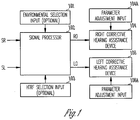
- Fig. 1 illustrates a basic system that includes a signal processor 102 for processing left and right stereo signals SL and SR in order to produce left and right simulated surround sound output signals LO and RO that can be used to drive left and right corrective hearing assistance devices 104 and 106.
- a corrective hearing assist device is any device that provides compensation for hearing loss by means of frequency selective amplification. Such devices would include, for example, behind-the-ear, in-the-ear, in-the-canal, and completely-in-the-canal hearing aids.
- the output signals LO and RO may be transferred to the direct audio input of a hearing assistance device by means of a wired or wireless connection.
- the hearing assistance device is equipped with a wireless receiver for receiving radiofrequency signals.
- the frequency selective amplification of the corrective hearing assistance devices, as well as well other parameters, may be adjusted by means of parameter adjustment inputs 104a and 106a for each of the devices 104 and 106, respectively.
- the signal processor 102 optionally has an environment selection input 101 for selecting particular acoustic environments. Some examples of acoustic environments include, but are not limited to, a classroom with moderate reverberation and a living room with low reverberation, a restaurant with high reverberation.
- the signal processor 102 also has an HRTF selection input 103 for selecting particular sets of HRTFs used to generate the simulated surround sound output signals. Some examples of HRTFs to select include, but are not limited to, those measured on a KEMAR manakin, those specific to and measured on the patient and those measured on a set of people whose HRTFs collectively span the expected HRTFs measured on any individual.
- Fig. 2 shows a particular example useful for understanding the present invention which is an example of the signal processor 102 that includes a surround sound synthesizer 206 for synthesizing the surround sound signals LS, L, C, R, and RS from the left and right stereo signals SL and SR.
- these signals are provided using techniques known to those in the art (e.g., Dolby Pro-Logic Decoder).
- the signal may also be generated using other sound process methods.
- the surround sound signals LS, L, C, R, and RS thus produced would create a surround sound environment by driving speakers located at the left rear, left front, center front, right front, and right rear of the listener, respectively.
- the surround sound signals are further processed by banks of head-related transfer functions to generate output signals RO and LO that can be used to drive devices providing a single acoustic output to each ear (i.e., corrective hearing assistance devices) and still generate the surround sound effect.
- Fig. 2 shows two filter banks 208R and 208L that process the surround sound signals for the right and left ears, respectively, with head-related transfer functions.
- the filter bank 208R processes the surround sound signals LS, L, C, R, and RS with head-related transfer functions HRTF 1 (R) through HRTF 5 (R), respectively, for the right ear.
- the filter bank 208L similarly processes the surround sound signals LS, L, C, R, and RS with head-related transfer functions HRTF 1 (L) through HRTF 5 (L), respectively, for the left ear.
- Each of the head-related transfer functions is a function of head anatomy (either the patient's individual anatomy or that of a model), the type of hearing assistance device to which to output signals RO and LO are to be input (e.g., behind-the-ear, in-the-ear, in-the-canal, and completely-in-the-canal hearing aids), and the azimuthal direction of the sound source to be simulated by it (i.e., the particular surround sound signal).
- the head-related transfer functions HRTF 1 (R) through HRTF 5 (R) and the functions HRTF 1 (L) through HRTF 5 (L) will be symmetrical but in certain instances may be asymmetrical.
- the outputs of each of the filter banks 208R and 208L are summed by summers 210 to produce the output signals RO and LO, respectively, used to drive the right and left hearing assistance devices.
- the surround sound synthesizer and filter banks are implemented by means of a memory adapted to store at least one head-related transfer function for each angle of reception to be synthesized and a processor connected to the memory and to a plurality of inputs including a stereo right (SR) input and a stereo left (SL) input.
- the processor is adapted to convert the SR and SL inputs into left surround (LS), left (L), center (C), right (R) and right surround (RS) signals, and further adapted to generate processed versions for each of the LS, L, C, R, and RS signals by application of a head-related transfer function at an individual angle of reception for each of the LS, L, C, R, and RS signals.
- the processor is further adapted to mix the processed versions of the LS, L, C, R, and RS signals to produce a right output signal (RO) and a left output signal (LO) for a first hearing assistance device and a second hearing assistance device, respectively.
- the output signals RO and LO may be immediately transferred to the hearing assistance devices as they are generated or may be stored in memory for later transfer to the hearing assistance devices.
- Fig. 3 shows another embodiment of the system shown in Fig. 2 to which has been added an HRTF selection input 312 for each of the filter banks 208R and 208L.
- This added functionality allows a user to select between different sets of head-related transfer functions for each ear. For example, the user may select between individualized or actual HRTFs and generic HRTFs or may adjust the individualized HRTFs in accordance with the subjective sensations reported by the patient.
- different sets of head-related transfer functions may be used during the hearing aid fitting process to produce different effects and further test the frequency response of the hearing aid. For example, sets of HRTFs that simulate sound direction that varies with elevation angle in addition to azimuth angle may be employed.
- Fig. 4 shows another example useful for understanding the present invention which is an example of the system shown in Fig. 2 to which has been added a sound environment selection input 411 to the surround sound synthesizer for selecting between different acoustic environments used to synthesize the surround sound signals from the stereo signals SL and SR.
- a sound environment selection input 411 to the surround sound synthesizer for selecting between different acoustic environments used to synthesize the surround sound signals from the stereo signals SL and SR.
- Employing different simulated acoustic environments with different reverberation characteristics adds complexity to the sound field produced by the output signals RO and LO that can be useful for testing the frequency response of the hearing aid.
- Presenting different acoustic environments to the patient also allows finer adjustment of hearing aid parameters in accordance with individual patient preferences.
- an input is provided to the surround sound synthesizer 206 that allows a user to adjust the spatial locations simulated by the surround sound signals.
- Fig. 5 shows an example of a system that includes a spatial location input 614 for the surround sound synthesizer 206 in addition to an HRTF selection input 312 for each of the filter banks and a sound environment selection input 411.
- the spatial location input 614 allows the surround sound signals generated by the surround sound synthesizer to be adjusted in a manner that varies the locations of the surround sound signals that are subsequently processed with the HRTFs to produce the output signals RO and LO.
- Spatial locations of the surround sound signals may be varied in discrete steps or varied dynamically to produce a panning effect. Varying the spatial location of sound sources in the simulated sound field allows further testing and adjustment of the hearing assistance device's frequency response in accordance with objective criteria and/or individual patient preferences.
Landscapes
- Engineering & Computer Science (AREA)
- Health & Medical Sciences (AREA)
- General Health & Medical Sciences (AREA)
- Neurosurgery (AREA)
- Otolaryngology (AREA)
- Physics & Mathematics (AREA)
- Acoustics & Sound (AREA)
- Signal Processing (AREA)
- Computer Networks & Wireless Communication (AREA)
- Stereophonic System (AREA)
Description
- This patent application pertains to devices and methods for treating hearing disorders and, in particular, to a simulated surround sound hearing aid fitting system for electronic hearing aids.
- Hearing aids are electronic instruments worn in or around the ear that compensate for hearing losses by amplifying and processing sound. The electronic circuitry of the device is contained within a housing that is commonly either placed in the external ear canal or behind the ear. Transducers for converting sound to an electrical signal and vice-versa may be integrated into the housing or external to it.
- Whether due to a conduction deficit or sensorineural damage, hearing loss in most patients occurs non-uniformly over the audio frequency range, most commonly at high frequencies. Hearing aids may be designed to compensate for such hearing deficits by amplifying received sound in a frequency-specific manner, thus acting as a kind of acoustic equalizer that compensates for the abnormal frequency response of the impaired ear. Adjusting a hearing aid's frequency specific amplification characteristics to achieve a desired level of compensation for an individual patient is referred to as fitting the hearing aid. One common way of fitting a hearing aid is to measure hearing loss, apply a fitting algorithm, and fine-tune the hearing aid parameters.
- Hearing loss is measured by testing the patient with a series of audio tones at different frequencies. The level of each tone is adjusted to a threshold level at which it is barely perceived by the patient, and the audiogram or hearing deficit at each tested frequency is quantified as the elevation of the patient's threshold above the level defined as normal by ANSI standards. For example, if the normal hearing threshold for a particular frequency is 4 dB SPL, and the patient's hearing threshold is 47 dB SPL, the patient is said to have 43 dB of hearing loss at that frequency.
- Compensation is then initially provided through a fitting algorithm. This is a formula which takes the patient's audiogram data as input to the formula and calculates gain and compression ratio at each frequency. A commonly used fitting algorithm is the NAL_NL1 fitting formula derived by the National Acoustic Laboratories in Australia and the DSL-i/o fitting formula derived at the University of Western Ontario. The audiogram provides only a simple characterization of the impairment to someone's ear and does not differentiate between different physiological mechanisms of loss such as inner ear cell damage, as opposed to, outer ear cell damage. Patients with the same audiogram often show considerable individual differences, with differences in their speech understanding ability, loudness perception, and hearing aid preference. Because of this, the initial fit based on the audiogram is not usually the best or final fit of the hearing aid parameters to the patient. In order to address individual differences, fine-tuning of the hearing aid parameters is conducted by the audiologists.
- Typically, the patient will wear a hearing aid for one-to-three weeks and return to the audiologist's office, whereupon the audiologist will make modifications to the hearing aid parameters based on the experience that the patient had with real-world sound in different environments, such as in a restaurant, in their kitchen or on a bus. For example, a patient may say that they like to listen to the radio while washing dishes, but with the hearing aid loud enough to hear the radio, the sound of the silverware hitting the dishes is sharp and unpleasant. The audiologist might make adjustments to the hearing aid by reducing the gain and adjusting the compression ratio in the high frequency region to preserve the listening experience of the radio while making the silverware sound more pleasant. Whether these adjustments solve the problem for the patient, however, will only be determined later when the patient experiences those problem sounds in those problem environments again. The patient may have to return to the audiologist's office several times for adjustments to their hearing aid until all sounds are set appropriately for their impairment and preference.
- This process could be improved if the audiologist were able to create a real-world experience so that the patient could instantly tell the audiologist if the adjustments that are made are successful or not. In the above example, if the audiologist could present the real-world sounds of a radio and a fork on a plate while washing dishes to the patient, the audiologist could make as many adjustments as necessary to optimize the hearing aid setting for that sound during a single office visit, rather than having to make an adjustment, have the patient go back home and experience the new setting, then come back to the office if the experience wasn't optimal.
- To address this problem, some hearing aid manufacturers have provided realistic sounds in their fitting software that use a 5.1 surround speaker setup. The surround sound is important because the spatial location can affect the sound quality and speech intelligibility of what they hear. Without it, the fine-tuning adjustments made in the audiologist's office may not be optimal for the real world in which the patient experiences problems. Also, natural reverberation, a problem sound for hearing aid wearers, is better reproduced with surround speakers than with a typical stereo front-placement speaker setup. Unfortunately, most audiologists' offices do not have 5.1 surround speaker setups, either due to cost, space, lack of supportive driving hardware, unfamiliarity with setup and calibration, or multiples of the above.
- Spatial hearing is an important ability in normal hearing individuals, with echo suppression, localization, and spatial release from masking being some of the benefits provided. Audiologists would like to be able to demonstrate that hearing aids provide these benefits to their patients, and this can be done with a surround speaker setup but not the typical two-speaker stereo setup that exists in most clinics. Any hearing aid algorithms that were developed for these spatial percepts will be difficult to demonstrate in the audiologist's office.
-
US Patent 5785661 discloses. A hearing aid fitting system for electronic hearing aids, comprising: a memory adapted to store at least one head-related transfer function; and a plurality of inputs including a stereo right, SR, input and a stereo left, SL, input; a processor connected to the memory and to the plurality of inputs, the processor adapted to process the plurality of input signals by application of selected head-related transfer functions; the processor adapted to mix the processed version of the plurality of input signals to produce a right output signal, RO, and a left output signal, LO, for a first hearing aid and a second hearing aid, wherein the system is adapted to provide the RO and LO signals directly to the first and second hearing aids via direct acoustic coupling. The present invention is a method as defined inClaim 1 and a system as defined in Claim 11. - This application provides methods and apparatus for fitting and fine-tuning a hearing aid by presenting to the hearing aid patient a spatial sound field having one or more localized sound sources without the need for a surround speaker setup. The parameters of the hearing aid may be adjusted in a manner that allows the patient to properly perceive the sound field, localize the sound source(s), and gain any available benefit from spatial perception. In one embodiment, a signal processing system employing head-related transfer functions ("HRTFs") is used to produce audio signals that simulate a three-dimensional sound field when a sound source producing such audio signals is coupled directly to one or both ears. By transmitting the audio signals produced by the signal processing system to the hearing aid, the hearing aid itself may be used as the sound source without requiring any surround speaker setup.
- This Summary is an overview of some of the teachings of the present application and is not intended to be an exclusive or exhaustive treatment of the present subject matter. Further details about the present subject matter are found in the detailed description and the appended claims. The scope of the present invention is defined by the appended claims and their legal equivalents.
-
-
Fig. 1 illustrates a basic system that includes a signal processor for processing left and right stereo signals in order to produce left and right simulated surround sound output signals that can be used to drive left and right corrective hearing assistance devices according to one embodiment of the present subject matter. -
Fig. 2 shows an example useful for understanding the present invention of the signal processor that includes a surround sound synthesizer for synthesizing the surround sound signals from the left and right stereo signals according to the present subject matter. -
Fig. 3 shows one embodiment of the system shown inFig. 2 to which has been added an HRTF selection input for each of the filter bank according to the present subject matter. -
Fig. 4 shows one example useful for understanding the present invention which is an example of the system shown inFig. 2 to which has been added a sound environment selection input to the surround sound synthesizer for selecting between different acoustic environments used to synthesize the surround sound signals from the stereo signals according to the present subject matter. -
Fig. 5 shows one embodiment of a system that includes a spatial location input for the surround sound synthesizer in addition to an HRTF selection input for each of the filter banks and a sound environment selection input according to the present subject matter. - The following detailed description of the present invention refers to subject matter in the accompanying drawings which show, by way of illustration, specific aspects and embodiments in which the present subject matter may be practiced. These embodiments are described in sufficient detail to enable those skilled in the art to practice the present subject matter. References to "an", "one", or "various" embodiments in this disclosure are not necessarily to the same embodiment, and such references contemplate more than one embodiment. The following detailed description is, therefore, not to be taken in a limiting sense, and the scope is defined only by the appended claims, along with the full scope of legal equivalents to which such claims are entitled.
- As part of the hearing aid fitting process, audiologists often present real-world types of sounds to the listener to determine if the settings are appropriate for such sounds and to adjust hearing aid parameters in accordance with the subjective preferences expressed by the user. Real-world types of sounds also allow the audiologist to demonstrate particular features of the hearing aid and to set realistic expectations for the hearing aid wearer. Typically, however, equipment for presenting such sounds consists only of two speakers attached to a computer. Multi-channel surround sound systems exist to play sounds from an array of speakers that number more than two (e.g., so-called 5.1 and 6.1 systems with speakers located in front of , to the sides of, and behind the listener). Such surround sound systems are capable of producing complex sound fields that incorporate information relating to the spatial location of different sound sources around the listener. Most audiologists, however, do not have this kind of hardware in their clinic or office. Audiologists are also often limited in the space that they have to locate speakers and often only have a desktop for the speakers. Also, the realistic quality of sound produced by a surround sound system with multiple speakers is highly dependent upon the acoustic environment in which the speakers are placed.
- Described herein is a hearing aid fitting system in which audio is transmitted directly into hearing aid rather than having the hearing aid pick up sound produced by external speakers. Audio signals can be transmitted to the hearing aid by a wire connected to the direct audio input (DAI) of the hearing aid or can be transmitted wirelessly to a receiver attached to the hearing aid DAI or to a receiver embedded in the hearing aid. Only a stereo (2-channel) signal is presented to the listener. In the case where the user wears two hearing aids, each hearing aid may receive one of the stereo signals. For a user who only wears one hearing aid, one stereo signal may be fed to the hearing aid, and the other stereo signal may be fed to a headphone or other device that acoustically couples directly to the ear. As described below, the stereo signals may be generated using signal processing algorithms in order to simulate a complex sound field such as may be produced by one or more sound sources located at different points around the listener.
- Although the means by which the human auditory system localizes sound sources in the environment is not completely understood, a number of different physical and physiological phenomena are known to be involved. The fact that humans have two ears on opposite sides of the head may cause binaural hearing differences that can be used by the brain to laterally locate a sound source. For example, if a sound source is located to the right of a listener's forward direction, the left ear is in the acoustic shadow cast by the listener's head. This causes the signal in the right ear to be more intense than the signal in the left ear which may serve as a clue that the sound source is located on the right. The difference between intensities in the left and right ears is known as the interaural level difference (ILD). Due to diffraction effects that reduce the acoustic shadow of the head, the ILD is small for frequencies below about 3000 Hz. At higher frequencies, however, the ILD is a significant source of information for sound localization. Another binaural hearing difference is the difference in the time it takes for sound waves emanating from a single source to reach the two ears. This time difference, referred to as the interaural time difference (ITD) and equivalent to a phase difference in the frequency domain, can be used by the auditory system to laterally locate a sound source if the wavelength of the sound wave is long compared with the difference in distance from each ear to the sound source. It has been found that the auditory system can most effectively use the ITD to locate pure tone sound sources at frequencies below about 1500 Hz.
- As noted above, the use of the ILD and ITD by the auditory system to localize sound sources is limited to particular frequency ranges. Furthermore, binaural hearing differences provide no information that would allow the auditory system to localize a sound source in the mid-sagittal plane (i.e., where the source is equidistant from each ear and located above, below, behind, or in front of the listener). Another acoustic phenomena utilized by the auditory system to overcome these limitations relates to the fact that sound waves coming from different directions in space are differently scattered by the listener's outer ears and head. This scattering causes an acoustical filtering of the signals eventually reaching the left and right ears, which filtering modifies the phases and amplitudes of the frequency components of the sound waves. The filtering thus constitutes a kind of spectral shaping that can be described by a directionally-dependent transfer function, referred to as the head-related transfer function (HRTF). The HRTF produces characteristic spectra for broad-band sounds emanating from different points in space that the brain learns to recognize and thus localize the source of the sound. Such HRTFs, which incorporate frequency-dependent amplitude and phase changes, also help in externalization and spatialization in general. If proper HRTFs are applied to both ears, proper ITD and ILD cues are also generated.
- As noted above, commercially available surround sound systems use multiple speakers surrounding a listener to generate more complex sound fields than can be obtained from systems having only one or two speakers. Surround sound recordings have separate surround sound output signals for driving each speaker of a surround sound system in order to generate the desired sound field. Technologies also exist for processing conventional two-channel stereo signals in order to synthesize separate surround sound output signals for driving each speaker of a surround sound system in a manner that approximates a specially made surround sound recording The Dolby Pro Logic II system is a commercially available example of this type of technology.
- Whether derived from a surround sound recording or synthesized from stereo signals, surround sound output signals can be further processed using synthesized HRTFs to generate audio that can be directly coupled to the ear (e.g., by headphones) and give the impression to the listener that different sounds are coming from different locations. A commercially available example of this technology is Dolby Headphone. For example, a surround sound output signal intended to drive a left rear speaker can be filtered with an HRTF that is synthesized to represent the actual HRTF of a listener for sounds coming from the left rear direction. The result is a signal that can be used to drive a headphone or other device directly acoustically coupled to the ear and produce sound that seems to the listener to be coming from the left rear direction. Separate signals for each ear can be generated using an HRTF specific for either the right or left ear. Multiple surround sound output signals can be similarly filtered with separate HRTFs for each ear and for each direction associated with a particular surround sound output signal. The multiple filtered signals can then be summed together to form simulated surround signals that can be used to drive a pair of headphones and generate a complex sound field containing all of the spatial information of the original surround sound output signals.
- A hearing aid fitting system as described herein employs simulated surround sound signals generated using HRTFs as described above to generate complex sound fields that can be used as part of the fitting process. Due to problems with feedback and background noise, hearing aid wearers cannot usually use headphones worn over their hearing aids. Audio signals intended to drive headphones, however, can be used to drive any type of device directly acoustically coupled to the ear including hearing aids with similar results. As described above, the simulated surround sound signals are transmitted via a wired or wireless connection to drive the speaker of a hearing aid. If the patient wears two hearing aids, both hearing aids are driven in this manner. If only one hearing aid is worn by the patient, that hearing aid may be driven by one simulated surround signal, with the other simulated surround sound signal used to drive another device such as a headphone or another hearing aid.
- The use of complex sounds as generated from simulated surround sound signals applied to the hearing aids enables the user to experience a variety of sonic environments. The parameters of the hearing aid may then be adjusted in accordance with the subjective preferences of the hearing aid wearer. Hearing aid testing with sounds encoded with spatial information also permits an objective determination of whether the hearing aid wearer properly perceives the direction of a sound source. As described above, such perception depends upon being able to recognize an audio spectrum that has been filtered by an HRTF. The interpretation of acoustic spectra produced by the HRTF is thus dependent upon the ear properly responding to the different frequency components of the spectra. That, in turn, is dependent upon the hearing aid providing adequate compensation for the patient's hearing loss over the range of frequencies represented by the filtered spectrum. This provides another way of testing the frequency response of the hearing aid. Hearing aid parameters may be adjusted in a manner that allows the patient to correctly perceive sound sources located at different locations from the simulated surround signals applied to the hearing aids.
- The sounds presented to the patient in the form of simulated surround sound may be derived from various sources such as music CDs or specially recorded or synthesized sounds. Audio samples may also be used that have been encoded such that when they are processed to generate simulated surround sound signals, a realistic surround audio environment is heard (e.g., a home environment or public place such as a restaurant). The hearing aid fitting system may also incorporate a 3D graphic system to create a more immersive environment for the hearing aid wearer being fitted. When such graphics are displayed in conjunction with the simulated surround sound, audiologists may find it easier to fit the hearing aids, better demonstrate features, and allow more realistic expectations to be set.
- Additionally, in various embodiments, sounds presented to the patient include sounds pre-recorded using the hearing assistance device. In various embodiments, the pre-recorded sound includes sounds recorded using a microphone positioned inside a user's ear canal. In various embodiments, the pre-recorded sound includes sounds recorded using a microphone positioned outside a user's ear canal. In various embodiments, the pre-recorded sound includes sounds recorded using a combination of microphones positioned both inside and outside the user's ear canal. Other sounds and sound sources may be used without departing from the scope of the present subject matter. The pre-recorded sounds, or statistics thereof, are subsequently downloaded to a fitting system according to the present subject matter and used to assist in fitting a user's hearing assistance system when played backed in simulated surround sound format.
-
Figs. 1 through 5 depict examples of signal processing systems that can be used to generate the simulated surround sound signals as described above. In these examples, five surround sound signals are generated and used to create the simulated surround sound signals for driving the hearing aids. Such systems could implemented in a personal computer (PC), where the audiologist selects any stereo sources and the software system creates simulated surround sound signals that will create a virtual surround sound environment when listened to through hearing aids. Alternatively, a small hardware processor can be attached to the PC sound card output that creates multiple surround sound channels, applies the HRTFs in real-time, and then transmits the simulated surround sound signals to the hearing aids via a wired or wireless connection. The HRTFs used in virtualizing the five surround sound channels may be generic ones, such as measured on a KEMAR. HRTFs may also be estimated by using a small number of measurements of the person's pinna. HRTFs could also be selected from a small set of HRTFs subjectively, where the subject listens to sounds through several HRTF sets and selects the one that sounds most realistic. -
Fig. 1 illustrates a basic system that includes asignal processor 102 for processing left and right stereo signals SL and SR in order to produce left and right simulated surround sound output signals LO and RO that can be used to drive left and right correctivehearing assistance devices devices signal processor 102 optionally has anenvironment selection input 101 for selecting particular acoustic environments. Some examples of acoustic environments include, but are not limited to, a classroom with moderate reverberation and a living room with low reverberation, a restaurant with high reverberation. Thesignal processor 102 also has anHRTF selection input 103 for selecting particular sets of HRTFs used to generate the simulated surround sound output signals. Some examples of HRTFs to select include, but are not limited to, those measured on a KEMAR manakin, those specific to and measured on the patient and those measured on a set of people whose HRTFs collectively span the expected HRTFs measured on any individual. -
Fig. 2 shows a particular example useful for understanding the present invention which is an example of thesignal processor 102 that includes asurround sound synthesizer 206 for synthesizing the surround sound signals LS, L, C, R, and RS from the left and right stereo signals SL and SR. In one embodiment, these signals are provided using techniques known to those in the art (e.g., Dolby Pro-Logic Decoder). The signal may also be generated using other sound process methods. The surround sound signals LS, L, C, R, and RS thus produced would create a surround sound environment by driving speakers located at the left rear, left front, center front, right front, and right rear of the listener, respectively. Rather than driving such speakers, however, the surround sound signals are further processed by banks of head-related transfer functions to generate output signals RO and LO that can be used to drive devices providing a single acoustic output to each ear (i.e., corrective hearing assistance devices) and still generate the surround sound effect.Fig. 2 shows twofilter banks filter bank 208R processes the surround sound signals LS, L, C, R, and RS with head-related transfer functions HRTF1(R) through HRTF5(R), respectively, for the right ear. Thefilter bank 208L similarly processes the surround sound signals LS, L, C, R, and RS with head-related transfer functions HRTF1(L) through HRTF5(L), respectively, for the left ear. Each of the head-related transfer functions is a function of head anatomy (either the patient's individual anatomy or that of a model), the type of hearing assistance device to which to output signals RO and LO are to be input (e.g., behind-the-ear, in-the-ear, in-the-canal, and completely-in-the-canal hearing aids), and the azimuthal direction of the sound source to be simulated by it (i.e., the particular surround sound signal). In most cases, the head-related transfer functions HRTF1(R) through HRTF5(R) and the functions HRTF1(L) through HRTF5(L) will be symmetrical but in certain instances may be asymmetrical. The outputs of each of thefilter banks summers 210 to produce the output signals RO and LO, respectively, used to drive the right and left hearing assistance devices. - In an exemplary embodiment, the surround sound synthesizer and filter banks are implemented by means of a memory adapted to store at least one head-related transfer function for each angle of reception to be synthesized and a processor connected to the memory and to a plurality of inputs including a stereo right (SR) input and a stereo left (SL) input. The processor is adapted to convert the SR and SL inputs into left surround (LS), left (L), center (C), right (R) and right surround (RS) signals, and further adapted to generate processed versions for each of the LS, L, C, R, and RS signals by application of a head-related transfer function at an individual angle of reception for each of the LS, L, C, R, and RS signals. The processor is further adapted to mix the processed versions of the LS, L, C, R, and RS signals to produce a right output signal (RO) and a left output signal (LO) for a first hearing assistance device and a second hearing assistance device, respectively. The output signals RO and LO may be immediately transferred to the hearing assistance devices as they are generated or may be stored in memory for later transfer to the hearing assistance devices.
-
Fig. 3 shows another embodiment of the system shown inFig. 2 to which has been added anHRTF selection input 312 for each of thefilter banks -
Fig. 4 shows another example useful for understanding the present invention which is an example of the system shown inFig. 2 to which has been added a soundenvironment selection input 411 to the surround sound synthesizer for selecting between different acoustic environments used to synthesize the surround sound signals from the stereo signals SL and SR. Employing different simulated acoustic environments with different reverberation characteristics adds complexity to the sound field produced by the output signals RO and LO that can be useful for testing the frequency response of the hearing aid. Presenting different acoustic environments to the patient also allows finer adjustment of hearing aid parameters in accordance with individual patient preferences. - In another embodiment of the system shown in
Fig. 2 , an input is provided to thesurround sound synthesizer 206 that allows a user to adjust the spatial locations simulated by the surround sound signals.Fig. 5 shows an example of a system that includes aspatial location input 614 for thesurround sound synthesizer 206 in addition to anHRTF selection input 312 for each of the filter banks and a soundenvironment selection input 411. Thespatial location input 614 allows the surround sound signals generated by the surround sound synthesizer to be adjusted in a manner that varies the locations of the surround sound signals that are subsequently processed with the HRTFs
to produce the output signals RO and LO. Spatial locations of the surround sound signals may be varied in discrete steps or varied dynamically to produce a panning effect. Varying the spatial location of sound sources in the simulated sound field allows further testing and adjustment of the hearing assistance device's frequency response in accordance with objective criteria and/or individual patient preferences.
Claims (14)
- A method for operating a hearing aid fitting system for electronic hearing aids, comprising:selecting between different sets of head-related transfer functions (208R, 208L) for each ear of a wearer of a right hearing aid (104) and a left hearing aid (106);receiving signals from a sound environment having a stereo right, SR, and a stereo left, SL, sound signal;processing the SR and SL signals to produce left surround, LS, left, L, center, C, right, R, and right surround, RS, signals;generating a processed version for each of the LS, L, C, R, and RS signals by application of a head-related transfer function at an individual angle of reception for each of the LS, L, C, R, and RS signals, the head-related transfer functions being head-related transfer functions of the set of head-related transfer functions selected for the each ear;mixing the processed version of the LS, L, C, R, and RS signals to produce a right output signal, RO, and a left output signal, LO;transferring directly, via wired or wireless radio connection, the RO signal to the right hearing aid and the LO signal to the left hearing aid; andadjusting parameters of the right hearing aid and the left hearing aid in a manner that allows the wearer to correctly perceive sound sources located at different locations from the RO signal applied to the right hearing aid and the LO signal applied to the left hearing aid.
- The method of claim 1, comprising using direct audio inputs of one or both of the right hearing aid and the left hearing aid.
- The method of any of the preceding claims, wherein the processing further comprises using generic head-related transfer functions.
- The method of any of the preceding claims, wherein the processing further comprises:measuring at least a portion of actual head-related transfer functions; andapplying the actual head-related transfer functions to generate the processed version for each of the LS, L, C, R, and RS signals.
- The method of any of the preceding claims, wherein the processing further comprises using a Dolby Pro-Logic 2 process.
- The method of any of the preceding claims, further comprising:generating a plurality of pre-recorded RO and LO signals; andstoring the plurality of pre-recorded RO and LO signals.
- The method of any of the preceding claims, wherein the head-related transfer function is processed for a wearer of completely-in-the-canal hearing assistance devices.
- The method of any of claims 1 to 6, wherein the head-related transfer function is processed for a wearer of in-the-canal hearing assistance devices.
- The method of any of claims 1 to 6, wherein the head-related transfer function is processed for a wearer of behind-the-ear hearing assistance devices.
- The method of any of claims 1 to 9, further comprising:selecting (411) an acoustic environment from different acoustic environments; andadjusting (614) the LS, L, C, R, and RS signals in a manner that varies locations of the LS, L, C, R, and RS signals prior to the generating the processed version for each of the LS, L, C, R, and RS signals.
- A hearing aid fitting system for electronic hearing aids, comprising:a memory adapted to store at least one head-related transfer function;a head-related transfer function selection input (103, 312) allowing a user to select between different sets of head-related transfer functions for each ear of the user; anda plurality of inputs including a stereo right, SR, input and a stereo left, SL, input;a processor (102) connected to the memory and to the plurality of inputs, the processor adapted to convert the SR and SL inputs into left surround, LS, left, L, center, C, right, R and right surround, RS, signals, the processor further adapted to generate a processed version for each of the LS, L, C, R, and RS signals by application of a head-related transfer function at an individual angle of reception for each of the LS, L, C, R, and RS signals,the head-related transfer functions being head-related transfer functions of the set of head-related transfer functions selected for the each ear;the processor adapted to mix the processed version of the LS, L, C, R, and RS signals to produce a right output signal, RO, and a left output signal, LO, for a first hearing aid (104) and a second hearing aid (106), wherein the system is adapted to transfer the RO and LO signals directly to the first and second hearing aids via wired or wireless radio connection; andmeans adapted to adjust parameters of the right hearing aid and the left hearing aid in a manner that allows the wearer to correctly perceive sound sources located at different locations from the RO signal applied to the right hearing aid and the LO signal applied to the left hearing aid.
- The system of claim 11, further comprising a plurality of pre-recorded RO and LO signals for different sound environments or different head related transfer functions or both.
- The system of either of claims 11 and 12, further comprising a sound environment selection input (411) for selection of one of a plurality of sound environments;
and
further comprising a spatial location input (614) adapted to allow the LS, L, C, R, and RS signals to be adjusted in a manner that varies locations of the LS, L, C, R, and RS signals before the generation of the processed version for each of the LS, L, C, R, and RS signals. - The system of any of claims 11 to 13, wherein the head-related transfer function is processed for a wearer of a particular type of hearing aid.
Applications Claiming Priority (1)
| Application Number | Priority Date | Filing Date | Title |
|---|---|---|---|
| US11/935,935 US9031242B2 (en) | 2007-11-06 | 2007-11-06 | Simulated surround sound hearing aid fitting system |
Publications (2)
| Publication Number | Publication Date |
|---|---|
| EP2099236A1 EP2099236A1 (en) | 2009-09-09 |
| EP2099236B1 true EP2099236B1 (en) | 2017-05-24 |
Family
ID=40588110
Family Applications (1)
| Application Number | Title | Priority Date | Filing Date |
|---|---|---|---|
| EP08253607.9A Revoked EP2099236B1 (en) | 2007-11-06 | 2008-11-05 | Simulated surround sound hearing aid fitting system |
Country Status (4)
| Country | Link |
|---|---|
| US (1) | US9031242B2 (en) |
| EP (1) | EP2099236B1 (en) |
| CA (1) | CA2642993A1 (en) |
| DK (1) | DK2099236T3 (en) |
Families Citing this family (32)
| Publication number | Priority date | Publication date | Assignee | Title |
|---|---|---|---|---|
| GB0724366D0 (en) * | 2007-12-14 | 2008-01-23 | Univ York | Environment modelling |
| KR100954385B1 (en) * | 2007-12-18 | 2010-04-26 | 한국전자통신연구원 | Apparatus and method for processing three dimensional audio signal using individualized hrtf, and high realistic multimedia playing system using it |
| US8705751B2 (en) * | 2008-06-02 | 2014-04-22 | Starkey Laboratories, Inc. | Compression and mixing for hearing assistance devices |
| US9185500B2 (en) | 2008-06-02 | 2015-11-10 | Starkey Laboratories, Inc. | Compression of spaced sources for hearing assistance devices |
| US9485589B2 (en) | 2008-06-02 | 2016-11-01 | Starkey Laboratories, Inc. | Enhanced dynamics processing of streaming audio by source separation and remixing |
| US9037468B2 (en) * | 2008-10-27 | 2015-05-19 | Sony Computer Entertainment Inc. | Sound localization for user in motion |
| US8553897B2 (en) * | 2009-06-09 | 2013-10-08 | Dean Robert Gary Anderson | Method and apparatus for directional acoustic fitting of hearing aids |
| US9101299B2 (en) * | 2009-07-23 | 2015-08-11 | Dean Robert Gary Anderson As Trustee Of The D/L Anderson Family Trust | Hearing aids configured for directional acoustic fitting |
| US8879745B2 (en) * | 2009-07-23 | 2014-11-04 | Dean Robert Gary Anderson As Trustee Of The D/L Anderson Family Trust | Method of deriving individualized gain compensation curves for hearing aid fitting |
| US9161131B2 (en) * | 2010-03-25 | 2015-10-13 | K&E Holdings, LLC | Stereo audio headphone apparatus for a user having a hearing loss and related methods |
| DK2643983T3 (en) | 2010-11-24 | 2015-01-26 | Phonak Ag | Hearing assistance system and method |
| US8942397B2 (en) | 2011-11-16 | 2015-01-27 | Dean Robert Gary Anderson | Method and apparatus for adding audible noise with time varying volume to audio devices |
| US9420386B2 (en) * | 2012-04-05 | 2016-08-16 | Sivantos Pte. Ltd. | Method for adjusting a hearing device apparatus and hearing device apparatus |
| DK2870779T3 (en) * | 2012-07-03 | 2017-12-04 | Sonova Ag | METHOD AND SYSTEM FOR THE ASSEMBLY OF HEARING AID, FOR SELECTING INDIVIDUALS IN CONSULTATION WITH HEARING AID AND / OR FOR DIAGNOSTIC HEARING TESTS OF HEARING AID |
| WO2014085510A1 (en) | 2012-11-30 | 2014-06-05 | Dts, Inc. | Method and apparatus for personalized audio virtualization |
| US9191755B2 (en) | 2012-12-14 | 2015-11-17 | Starkey Laboratories, Inc. | Spatial enhancement mode for hearing aids |
| WO2014164361A1 (en) | 2013-03-13 | 2014-10-09 | Dts Llc | System and methods for processing stereo audio content |
| DK2822301T3 (en) * | 2013-07-04 | 2019-07-01 | Gn Hearing As | Determination of individual HRTF |
| KR20150020810A (en) * | 2013-08-19 | 2015-02-27 | 삼성전자주식회사 | Method for fitting a hearing aid using binaural hearing model and hearing aid enabling the method |
| CN107996028A (en) * | 2015-03-10 | 2018-05-04 | Ossic公司 | Calibrate hearing prosthesis |
| WO2017097324A1 (en) * | 2015-12-07 | 2017-06-15 | Huawei Technologies Co., Ltd. | An audio signal processing apparatus and method |
| US10142743B2 (en) | 2016-01-01 | 2018-11-27 | Dean Robert Gary Anderson | Parametrically formulated noise and audio systems, devices, and methods thereof |
| CN108778410B (en) * | 2016-03-11 | 2022-05-27 | 梅约医学教育与研究基金会 | Cochlear stimulation system with surround sound and noise cancellation |
| US9955279B2 (en) | 2016-05-11 | 2018-04-24 | Ossic Corporation | Systems and methods of calibrating earphones |
| US10492018B1 (en) | 2016-10-11 | 2019-11-26 | Google Llc | Symmetric binaural rendering for high-order ambisonics |
| US9992602B1 (en) | 2017-01-12 | 2018-06-05 | Google Llc | Decoupled binaural rendering |
| US10158963B2 (en) | 2017-01-30 | 2018-12-18 | Google Llc | Ambisonic audio with non-head tracked stereo based on head position and time |
| US10009704B1 (en) * | 2017-01-30 | 2018-06-26 | Google Llc | Symmetric spherical harmonic HRTF rendering |
| US11924612B2 (en) | 2017-10-05 | 2024-03-05 | Cochlear Limited | Distraction remediation at a hearing device |
| US10681475B2 (en) * | 2018-02-17 | 2020-06-09 | The United States Of America As Represented By The Secretary Of The Defense | System and method for evaluating speech perception in complex listening environments |
| DE102018210053A1 (en) * | 2018-06-20 | 2019-12-24 | Sivantos Pte. Ltd. | Process for audio playback in a hearing aid |
| CN113556660B (en) * | 2021-08-01 | 2022-07-19 | 武汉左点科技有限公司 | Hearing-aid method and device based on virtual surround sound technology |
Citations (8)
| Publication number | Priority date | Publication date | Assignee | Title |
|---|---|---|---|---|
| US5785661A (en) | 1994-08-17 | 1998-07-28 | Decibel Instruments, Inc. | Highly configurable hearing aid |
| US20030044002A1 (en) | 2001-08-28 | 2003-03-06 | Yeager David M. | Three dimensional audio telephony |
| US6614910B1 (en) | 1996-11-01 | 2003-09-02 | Central Research Laboratories Limited | Stereo sound expander |
| US20040218771A1 (en) | 2003-04-22 | 2004-11-04 | Siemens Audiologische Technik Gmbh | Method for production of an approximated partial transfer function |
| EP1531650A2 (en) | 2003-11-12 | 2005-05-18 | Gennum Corporation | Hearing instrument having a wireless base unit |
| US20050271212A1 (en) | 2002-07-02 | 2005-12-08 | Thales | Sound source spatialization system |
| EP1796427A1 (en) | 2005-12-07 | 2007-06-13 | Phonak AG | Hearing device with virtual sound source |
| WO2007106553A1 (en) | 2006-03-15 | 2007-09-20 | Dolby Laboratories Licensing Corporation | Binaural rendering using subband filters |
Family Cites Families (25)
| Publication number | Priority date | Publication date | Assignee | Title |
|---|---|---|---|---|
| US4406001A (en) | 1980-08-18 | 1983-09-20 | The Variable Speech Control Company ("Vsc") | Time compression/expansion with synchronized individual pitch correction of separate components |
| GB2192511B (en) | 1986-07-11 | 1990-02-21 | Roger Frederick Laurence | Hearing aid |
| US6885752B1 (en) | 1994-07-08 | 2005-04-26 | Brigham Young University | Hearing aid device incorporating signal processing techniques |
| US5825894A (en) * | 1994-08-17 | 1998-10-20 | Decibel Instruments, Inc. | Spatialization for hearing evaluation |
| US6405163B1 (en) | 1999-09-27 | 2002-06-11 | Creative Technology Ltd. | Process for removing voice from stereo recordings |
| US7340062B2 (en) | 2000-03-14 | 2008-03-04 | Revit Lawrence J | Sound reproduction method and apparatus for assessing real-world performance of hearing and hearing aids |
| AU2001246395A1 (en) | 2000-04-04 | 2001-10-15 | Gn Resound A/S | A hearing prosthesis with automatic classification of the listening environment |
| ATE546018T1 (en) * | 2000-08-31 | 2012-03-15 | Dolby Lab Licensing Corp | METHOD AND ARRANGEMENT FOR AUDIO MATRIX DECODING |
| US7630507B2 (en) | 2002-01-28 | 2009-12-08 | Gn Resound A/S | Binaural compression system |
| US7409068B2 (en) | 2002-03-08 | 2008-08-05 | Sound Design Technologies, Ltd. | Low-noise directional microphone system |
| US7330556B2 (en) | 2003-04-03 | 2008-02-12 | Gn Resound A/S | Binaural signal enhancement system |
| KR20050060789A (en) * | 2003-12-17 | 2005-06-22 | 삼성전자주식회사 | Apparatus and method for controlling virtual sound |
| KR100647286B1 (en) | 2004-08-14 | 2006-11-23 | 삼성전자주식회사 | Postprocessing apparatus and method for removing cross-channel interference and apparatus and method for separating multi-channel sources employing the same |
| KR20060022968A (en) * | 2004-09-08 | 2006-03-13 | 삼성전자주식회사 | Sound reproducing apparatus and sound reproducing method |
| US7634092B2 (en) * | 2004-10-14 | 2009-12-15 | Dolby Laboratories Licensing Corporation | Head related transfer functions for panned stereo audio content |
| DE102004053790A1 (en) | 2004-11-08 | 2006-05-18 | Siemens Audiologische Technik Gmbh | Method for generating stereo signals for separate sources and corresponding acoustic system |
| US7912232B2 (en) | 2005-09-30 | 2011-03-22 | Aaron Master | Method and apparatus for removing or isolating voice or instruments on stereo recordings |
| JP5081838B2 (en) * | 2006-02-21 | 2012-11-28 | コーニンクレッカ フィリップス エレクトロニクス エヌ ヴィ | Audio encoding and decoding |
| JP4672611B2 (en) | 2006-07-28 | 2011-04-20 | 株式会社神戸製鋼所 | Sound source separation apparatus, sound source separation method, and sound source separation program |
| US20100040135A1 (en) * | 2006-09-29 | 2010-02-18 | Lg Electronics Inc. | Apparatus for processing mix signal and method thereof |
| DE102006047983A1 (en) | 2006-10-10 | 2008-04-24 | Siemens Audiologische Technik Gmbh | Processing an input signal in a hearing aid |
| DE102006047986B4 (en) | 2006-10-10 | 2012-06-14 | Siemens Audiologische Technik Gmbh | Processing an input signal in a hearing aid |
| US9485589B2 (en) | 2008-06-02 | 2016-11-01 | Starkey Laboratories, Inc. | Enhanced dynamics processing of streaming audio by source separation and remixing |
| US9185500B2 (en) | 2008-06-02 | 2015-11-10 | Starkey Laboratories, Inc. | Compression of spaced sources for hearing assistance devices |
| US9084893B2 (en) | 2009-02-03 | 2015-07-21 | Hearworks Pty Ltd | Enhanced envelope encoded tone, sound processor and system |
-
2007
- 2007-11-06 US US11/935,935 patent/US9031242B2/en active Active
-
2008
- 2008-11-05 DK DK08253607.9T patent/DK2099236T3/en active
- 2008-11-05 EP EP08253607.9A patent/EP2099236B1/en not_active Revoked
- 2008-11-05 CA CA 2642993 patent/CA2642993A1/en not_active Abandoned
Patent Citations (8)
| Publication number | Priority date | Publication date | Assignee | Title |
|---|---|---|---|---|
| US5785661A (en) | 1994-08-17 | 1998-07-28 | Decibel Instruments, Inc. | Highly configurable hearing aid |
| US6614910B1 (en) | 1996-11-01 | 2003-09-02 | Central Research Laboratories Limited | Stereo sound expander |
| US20030044002A1 (en) | 2001-08-28 | 2003-03-06 | Yeager David M. | Three dimensional audio telephony |
| US20050271212A1 (en) | 2002-07-02 | 2005-12-08 | Thales | Sound source spatialization system |
| US20040218771A1 (en) | 2003-04-22 | 2004-11-04 | Siemens Audiologische Technik Gmbh | Method for production of an approximated partial transfer function |
| EP1531650A2 (en) | 2003-11-12 | 2005-05-18 | Gennum Corporation | Hearing instrument having a wireless base unit |
| EP1796427A1 (en) | 2005-12-07 | 2007-06-13 | Phonak AG | Hearing device with virtual sound source |
| WO2007106553A1 (en) | 2006-03-15 | 2007-09-20 | Dolby Laboratories Licensing Corporation | Binaural rendering using subband filters |
Non-Patent Citations (3)
| Title |
|---|
| FORTSCHRITTE DER AKUSTIK : PLENARVORTRAGE UND FACHBEITRAGE DER 27. DEUTSCHEN JAHRESTAGUNG FUR AKUSTIK DAGA 2001, Hamburg |
| GARDNER ET AL.: "HRTF Measurements of a KEMAR Dummy-Head Microphone", MIT MEDIA LAB PERCEPTUAL COMPUTING TR #280, May 1994 (1994-05-01), XP055467350, Retrieved from the Internet <URL:http://sound.media.mit.edu/resources/KEMAR/hrtfdoc.txt> |
| SEEBER ET AL.: "Effiziente Auswahl der individuell-optimalen aus fremden Außenohrübertragungsfunktionen", TAGUNGSBAND DAGA 2001 , DT. GESELLSCHAFT FUR AKUSTIK, 2001, Oldenburg, XP055467346 |
Also Published As
| Publication number | Publication date |
|---|---|
| US9031242B2 (en) | 2015-05-12 |
| US20090116657A1 (en) | 2009-05-07 |
| CA2642993A1 (en) | 2009-05-06 |
| DK2099236T3 (en) | 2017-09-11 |
| EP2099236A1 (en) | 2009-09-09 |
Similar Documents
| Publication | Publication Date | Title |
|---|---|---|
| EP2099236B1 (en) | Simulated surround sound hearing aid fitting system | |
| US10431239B2 (en) | Hearing system | |
| JP5894634B2 (en) | Determination of HRTF for each individual | |
| US9930456B2 (en) | Method and apparatus for localization of streaming sources in hearing assistance system | |
| Pralong et al. | The role of individualized headphone calibration for the generation of high fidelity virtual auditory space | |
| JP5325988B2 (en) | Method for rendering binaural stereo in a hearing aid system and hearing aid system | |
| Ricketts et al. | Evaluation of an adaptive, directional-microphone hearing aid: Evaluación de un auxiliar auditivo de micrófono direccional adaptable | |
| EP2993919B1 (en) | Binaural hearing system and method | |
| Denk et al. | On the limitations of sound localization with hearing devices | |
| Stenfelt et al. | Binaural hearing ability with mastoid applied bilateral bone conduction stimulation in normal hearing subjects | |
| Kates et al. | Externalization of remote microphone signals using a structural binaural model of the head and pinna | |
| Dieudonné et al. | Head shadow enhancement with low-frequency beamforming improves sound localization and speech perception for simulated bimodal listeners | |
| Zheng et al. | Sound localization of listeners with normal hearing, impaired hearing, hearing aids, bone-anchored hearing instruments, and cochlear implants: a review | |
| US8666080B2 (en) | Method for processing a multi-channel audio signal for a binaural hearing apparatus and a corresponding hearing apparatus | |
| EP2822301A1 (en) | Determination of individual HRTFs | |
| US9532146B2 (en) | Method and apparatus for testing binaural hearing aid function | |
| Flanagan et al. | Discrimination of group delay in clicklike signals presented via headphones and loudspeakers | |
| EP4094685B1 (en) | Spectro-temporal modulation detection test unit | |
| Pausch | Spatial audio reproduction for hearing aid research: System design, evaluation and application | |
| Koski | Parametric Spatial Audio in Hearing Performance Evaluation of Hearing-Impaired and Aided Listeners | |
| Kates et al. | Improving auditory externalization for hearing-aid remote microphones | |
| Lennox et al. | The body as instrument: tissue conducted multimodal audio-tactile spatial music. | |
| McKenzie et al. | Tissue-conducted spatial sound fields | |
| Lennox et al. | The body as instrument: tissue | |
| Fernandez | Localisation of Virtual Sound Sources by Bilateral Cochlear Implant Users |
Legal Events
| Date | Code | Title | Description |
|---|---|---|---|
| PUAI | Public reference made under article 153(3) epc to a published international application that has entered the european phase |
Free format text: ORIGINAL CODE: 0009012 |
|
| 17P | Request for examination filed |
Effective date: 20081112 |
|
| AK | Designated contracting states |
Kind code of ref document: A1 Designated state(s): AT BE BG CH CY CZ DE DK EE ES FI FR GB GR HR HU IE IS IT LI LT LU LV MC MT NL NO PL PT RO SE SI SK TR |
|
| AX | Request for extension of the european patent |
Extension state: AL BA MK RS |
|
| 17Q | First examination report despatched |
Effective date: 20100319 |
|
| AKX | Designation fees paid |
Designated state(s): AT BE BG CH CY CZ DE DK EE ES FI FR GB GR HR HU IE IS IT LI LT LU LV MC MT NL NO PL PT RO SE SI SK TR |
|
| GRAP | Despatch of communication of intention to grant a patent |
Free format text: ORIGINAL CODE: EPIDOSNIGR1 |
|
| STAA | Information on the status of an ep patent application or granted ep patent |
Free format text: STATUS: GRANT OF PATENT IS INTENDED |
|
| INTG | Intention to grant announced |
Effective date: 20161121 |
|
| GRAS | Grant fee paid |
Free format text: ORIGINAL CODE: EPIDOSNIGR3 |
|
| GRAJ | Information related to disapproval of communication of intention to grant by the applicant or resumption of examination proceedings by the epo deleted |
Free format text: ORIGINAL CODE: EPIDOSDIGR1 |
|
| GRAL | Information related to payment of fee for publishing/printing deleted |
Free format text: ORIGINAL CODE: EPIDOSDIGR3 |
|
| STAA | Information on the status of an ep patent application or granted ep patent |
Free format text: STATUS: EXAMINATION IS IN PROGRESS |
|
| GRAR | Information related to intention to grant a patent recorded |
Free format text: ORIGINAL CODE: EPIDOSNIGR71 |
|
| STAA | Information on the status of an ep patent application or granted ep patent |
Free format text: STATUS: GRANT OF PATENT IS INTENDED |
|
| GRAA | (expected) grant |
Free format text: ORIGINAL CODE: 0009210 |
|
| STAA | Information on the status of an ep patent application or granted ep patent |
Free format text: STATUS: THE PATENT HAS BEEN GRANTED |
|
| INTC | Intention to grant announced (deleted) | ||
| AK | Designated contracting states |
Kind code of ref document: B1 Designated state(s): AT BE BG CH CY CZ DE DK EE ES FI FR GB GR HR HU IE IS IT LI LT LU LV MC MT NL NO PL PT RO SE SI SK TR |
|
| INTG | Intention to grant announced |
Effective date: 20170418 |
|
| REG | Reference to a national code |
Ref country code: GB Ref legal event code: FG4D |
|
| REG | Reference to a national code |
Ref country code: CH Ref legal event code: EP Ref country code: CH Ref legal event code: NV Representative=s name: SERVOPATENT GMBH, CH |
|
| REG | Reference to a national code |
Ref country code: IE Ref legal event code: FG4D |
|
| REG | Reference to a national code |
Ref country code: AT Ref legal event code: REF Ref document number: 896543 Country of ref document: AT Kind code of ref document: T Effective date: 20170615 |
|
| REG | Reference to a national code |
Ref country code: DE Ref legal event code: R096 Ref document number: 602008050387 Country of ref document: DE |
|
| REG | Reference to a national code |
Ref country code: DK Ref legal event code: T3 Effective date: 20170905 |
|
| REG | Reference to a national code |
Ref country code: NL Ref legal event code: MP Effective date: 20170524 |
|
| REG | Reference to a national code |
Ref country code: LT Ref legal event code: MG4D |
|
| REG | Reference to a national code |
Ref country code: FR Ref legal event code: PLFP Year of fee payment: 10 |
|
| REG | Reference to a national code |
Ref country code: AT Ref legal event code: MK05 Ref document number: 896543 Country of ref document: AT Kind code of ref document: T Effective date: 20170524 |
|
| PG25 | Lapsed in a contracting state [announced via postgrant information from national office to epo] |
Ref country code: ES Free format text: LAPSE BECAUSE OF FAILURE TO SUBMIT A TRANSLATION OF THE DESCRIPTION OR TO PAY THE FEE WITHIN THE PRESCRIBED TIME-LIMIT Effective date: 20170524 Ref country code: LT Free format text: LAPSE BECAUSE OF FAILURE TO SUBMIT A TRANSLATION OF THE DESCRIPTION OR TO PAY THE FEE WITHIN THE PRESCRIBED TIME-LIMIT Effective date: 20170524 Ref country code: NO Free format text: LAPSE BECAUSE OF FAILURE TO SUBMIT A TRANSLATION OF THE DESCRIPTION OR TO PAY THE FEE WITHIN THE PRESCRIBED TIME-LIMIT Effective date: 20170824 Ref country code: HR Free format text: LAPSE BECAUSE OF FAILURE TO SUBMIT A TRANSLATION OF THE DESCRIPTION OR TO PAY THE FEE WITHIN THE PRESCRIBED TIME-LIMIT Effective date: 20170524 Ref country code: FI Free format text: LAPSE BECAUSE OF FAILURE TO SUBMIT A TRANSLATION OF THE DESCRIPTION OR TO PAY THE FEE WITHIN THE PRESCRIBED TIME-LIMIT Effective date: 20170524 Ref country code: GR Free format text: LAPSE BECAUSE OF FAILURE TO SUBMIT A TRANSLATION OF THE DESCRIPTION OR TO PAY THE FEE WITHIN THE PRESCRIBED TIME-LIMIT Effective date: 20170825 Ref country code: AT Free format text: LAPSE BECAUSE OF FAILURE TO SUBMIT A TRANSLATION OF THE DESCRIPTION OR TO PAY THE FEE WITHIN THE PRESCRIBED TIME-LIMIT Effective date: 20170524 |
|
| PG25 | Lapsed in a contracting state [announced via postgrant information from national office to epo] |
Ref country code: NL Free format text: LAPSE BECAUSE OF FAILURE TO SUBMIT A TRANSLATION OF THE DESCRIPTION OR TO PAY THE FEE WITHIN THE PRESCRIBED TIME-LIMIT Effective date: 20170524 Ref country code: SE Free format text: LAPSE BECAUSE OF FAILURE TO SUBMIT A TRANSLATION OF THE DESCRIPTION OR TO PAY THE FEE WITHIN THE PRESCRIBED TIME-LIMIT Effective date: 20170524 Ref country code: BG Free format text: LAPSE BECAUSE OF FAILURE TO SUBMIT A TRANSLATION OF THE DESCRIPTION OR TO PAY THE FEE WITHIN THE PRESCRIBED TIME-LIMIT Effective date: 20170824 Ref country code: IS Free format text: LAPSE BECAUSE OF FAILURE TO SUBMIT A TRANSLATION OF THE DESCRIPTION OR TO PAY THE FEE WITHIN THE PRESCRIBED TIME-LIMIT Effective date: 20170924 Ref country code: LV Free format text: LAPSE BECAUSE OF FAILURE TO SUBMIT A TRANSLATION OF THE DESCRIPTION OR TO PAY THE FEE WITHIN THE PRESCRIBED TIME-LIMIT Effective date: 20170524 |
|
| PG25 | Lapsed in a contracting state [announced via postgrant information from national office to epo] |
Ref country code: CZ Free format text: LAPSE BECAUSE OF FAILURE TO SUBMIT A TRANSLATION OF THE DESCRIPTION OR TO PAY THE FEE WITHIN THE PRESCRIBED TIME-LIMIT Effective date: 20170524 Ref country code: EE Free format text: LAPSE BECAUSE OF FAILURE TO SUBMIT A TRANSLATION OF THE DESCRIPTION OR TO PAY THE FEE WITHIN THE PRESCRIBED TIME-LIMIT Effective date: 20170524 Ref country code: SK Free format text: LAPSE BECAUSE OF FAILURE TO SUBMIT A TRANSLATION OF THE DESCRIPTION OR TO PAY THE FEE WITHIN THE PRESCRIBED TIME-LIMIT Effective date: 20170524 Ref country code: RO Free format text: LAPSE BECAUSE OF FAILURE TO SUBMIT A TRANSLATION OF THE DESCRIPTION OR TO PAY THE FEE WITHIN THE PRESCRIBED TIME-LIMIT Effective date: 20170524 |
|
| REG | Reference to a national code |
Ref country code: DE Ref legal event code: R026 Ref document number: 602008050387 Country of ref document: DE |
|
| PG25 | Lapsed in a contracting state [announced via postgrant information from national office to epo] |
Ref country code: PL Free format text: LAPSE BECAUSE OF FAILURE TO SUBMIT A TRANSLATION OF THE DESCRIPTION OR TO PAY THE FEE WITHIN THE PRESCRIBED TIME-LIMIT Effective date: 20170524 Ref country code: IT Free format text: LAPSE BECAUSE OF FAILURE TO SUBMIT A TRANSLATION OF THE DESCRIPTION OR TO PAY THE FEE WITHIN THE PRESCRIBED TIME-LIMIT Effective date: 20170524 |
|
| PLBI | Opposition filed |
Free format text: ORIGINAL CODE: 0009260 |
|
| PLAX | Notice of opposition and request to file observation + time limit sent |
Free format text: ORIGINAL CODE: EPIDOSNOBS2 |
|
| 26 | Opposition filed |
Opponent name: OTICON A/S / GN RESOUND A/S / WIDEX A/S Effective date: 20180226 |
|
| PG25 | Lapsed in a contracting state [announced via postgrant information from national office to epo] |
Ref country code: SI Free format text: LAPSE BECAUSE OF FAILURE TO SUBMIT A TRANSLATION OF THE DESCRIPTION OR TO PAY THE FEE WITHIN THE PRESCRIBED TIME-LIMIT Effective date: 20170524 |
|
| PG25 | Lapsed in a contracting state [announced via postgrant information from national office to epo] |
Ref country code: MC Free format text: LAPSE BECAUSE OF FAILURE TO SUBMIT A TRANSLATION OF THE DESCRIPTION OR TO PAY THE FEE WITHIN THE PRESCRIBED TIME-LIMIT Effective date: 20170524 |
|
| GBPC | Gb: european patent ceased through non-payment of renewal fee |
Effective date: 20171105 |
|
| PG25 | Lapsed in a contracting state [announced via postgrant information from national office to epo] |
Ref country code: LU Free format text: LAPSE BECAUSE OF NON-PAYMENT OF DUE FEES Effective date: 20171105 |
|
| REG | Reference to a national code |
Ref country code: BE Ref legal event code: MM Effective date: 20171130 |
|
| REG | Reference to a national code |
Ref country code: IE Ref legal event code: MM4A |
|
| PLBB | Reply of patent proprietor to notice(s) of opposition received |
Free format text: ORIGINAL CODE: EPIDOSNOBS3 |
|
| PG25 | Lapsed in a contracting state [announced via postgrant information from national office to epo] |
Ref country code: MT Free format text: LAPSE BECAUSE OF NON-PAYMENT OF DUE FEES Effective date: 20171105 |
|
| REG | Reference to a national code |
Ref country code: FR Ref legal event code: PLFP Year of fee payment: 11 |
|
| PG25 | Lapsed in a contracting state [announced via postgrant information from national office to epo] |
Ref country code: IE Free format text: LAPSE BECAUSE OF NON-PAYMENT OF DUE FEES Effective date: 20171105 |
|
| PG25 | Lapsed in a contracting state [announced via postgrant information from national office to epo] |
Ref country code: GB Free format text: LAPSE BECAUSE OF NON-PAYMENT OF DUE FEES Effective date: 20171105 Ref country code: BE Free format text: LAPSE BECAUSE OF NON-PAYMENT OF DUE FEES Effective date: 20171130 |
|
| REG | Reference to a national code |
Ref country code: DE Ref legal event code: R100 Ref document number: 602008050387 Country of ref document: DE |
|
| PG25 | Lapsed in a contracting state [announced via postgrant information from national office to epo] |
Ref country code: HU Free format text: LAPSE BECAUSE OF FAILURE TO SUBMIT A TRANSLATION OF THE DESCRIPTION OR TO PAY THE FEE WITHIN THE PRESCRIBED TIME-LIMIT; INVALID AB INITIO Effective date: 20081105 |
|
| PLCK | Communication despatched that opposition was rejected |
Free format text: ORIGINAL CODE: EPIDOSNREJ1 |
|
| APBM | Appeal reference recorded |
Free format text: ORIGINAL CODE: EPIDOSNREFNO |
|
| APBP | Date of receipt of notice of appeal recorded |
Free format text: ORIGINAL CODE: EPIDOSNNOA2O |
|
| APAH | Appeal reference modified |
Free format text: ORIGINAL CODE: EPIDOSCREFNO |
|
| APAJ | Date of receipt of notice of appeal modified |
Free format text: ORIGINAL CODE: EPIDOSCNOA2O |
|
| PG25 | Lapsed in a contracting state [announced via postgrant information from national office to epo] |
Ref country code: CY Free format text: LAPSE BECAUSE OF NON-PAYMENT OF DUE FEES Effective date: 20170524 |
|
| APBQ | Date of receipt of statement of grounds of appeal recorded |
Free format text: ORIGINAL CODE: EPIDOSNNOA3O |
|
| PG25 | Lapsed in a contracting state [announced via postgrant information from national office to epo] |
Ref country code: TR Free format text: LAPSE BECAUSE OF FAILURE TO SUBMIT A TRANSLATION OF THE DESCRIPTION OR TO PAY THE FEE WITHIN THE PRESCRIBED TIME-LIMIT Effective date: 20170524 |
|
| PG25 | Lapsed in a contracting state [announced via postgrant information from national office to epo] |
Ref country code: PT Free format text: LAPSE BECAUSE OF FAILURE TO SUBMIT A TRANSLATION OF THE DESCRIPTION OR TO PAY THE FEE WITHIN THE PRESCRIBED TIME-LIMIT Effective date: 20170524 |
|
| REG | Reference to a national code |
Ref country code: CH Ref legal event code: PCAR Free format text: NEW ADDRESS: WANNERSTRASSE 9/1, 8045 ZUERICH (CH) |
|
| PGFP | Annual fee paid to national office [announced via postgrant information from national office to epo] |
Ref country code: CH Payment date: 20201125 Year of fee payment: 13 |
|
| PGFP | Annual fee paid to national office [announced via postgrant information from national office to epo] |
Ref country code: DE Payment date: 20211013 Year of fee payment: 14 Ref country code: DK Payment date: 20211011 Year of fee payment: 14 |
|
| PGFP | Annual fee paid to national office [announced via postgrant information from national office to epo] |
Ref country code: FR Payment date: 20211012 Year of fee payment: 14 |
|
| APBU | Appeal procedure closed |
Free format text: ORIGINAL CODE: EPIDOSNNOA9O |
|
| RDAF | Communication despatched that patent is revoked |
Free format text: ORIGINAL CODE: EPIDOSNREV1 |
|
| REG | Reference to a national code |
Ref country code: DE Ref legal event code: R103 Ref document number: 602008050387 Country of ref document: DE Ref country code: DE Ref legal event code: R064 Ref document number: 602008050387 Country of ref document: DE |
|
| RDAG | Patent revoked |
Free format text: ORIGINAL CODE: 0009271 |
|
| STAA | Information on the status of an ep patent application or granted ep patent |
Free format text: STATUS: PATENT REVOKED |
|
| REG | Reference to a national code |
Ref country code: CH Ref legal event code: PL |
|
| REG | Reference to a national code |
Ref country code: FI Ref legal event code: MGE |
|
| 27W | Patent revoked |
Effective date: 20220408 |
|
| P01 | Opt-out of the competence of the unified patent court (upc) registered |
Effective date: 20230610 |