EP2098876A1 - The method for determining the minimum measurement distance of antenna - Google Patents
The method for determining the minimum measurement distance of antenna Download PDFInfo
- Publication number
- EP2098876A1 EP2098876A1 EP07721176A EP07721176A EP2098876A1 EP 2098876 A1 EP2098876 A1 EP 2098876A1 EP 07721176 A EP07721176 A EP 07721176A EP 07721176 A EP07721176 A EP 07721176A EP 2098876 A1 EP2098876 A1 EP 2098876A1
- Authority
- EP
- European Patent Office
- Prior art keywords
- antenna
- mobile terminal
- electromagnetic scattering
- distance
- wireless mobile
- Prior art date
- Legal status (The legal status is an assumption and is not a legal conclusion. Google has not performed a legal analysis and makes no representation as to the accuracy of the status listed.)
- Granted
Links
Images


Classifications
-
- G—PHYSICS
- G01—MEASURING; TESTING
- G01R—MEASURING ELECTRIC VARIABLES; MEASURING MAGNETIC VARIABLES
- G01R29/00—Arrangements for measuring or indicating electric quantities not covered by groups G01R19/00 - G01R27/00
- G01R29/08—Measuring electromagnetic field characteristics
- G01R29/10—Radiation diagrams of antennas
Definitions
- the mobile phone to be tested and the antenna thereof are processed according to the Black-box, that is, detailed process of the mobile phone to be tested and the antenna thereof will be not involved.
- Preferred embodiments of the present invention will be illustrated in combination with the accompanying drawings in details as follows. If not conflict, the embodiments and the technical features of the embodiments can be combined with each other.
- the electromagnetic scattering dimension is the minimum diameter of a spherical surface encircling the wireless mobile terminal to be tested and the electromagnetic scattering body in the predetermined spatial area.
- the electromagnetic scattering body in the predetermined spatial area is a human body and the electromagnetic scattering body comprises the head of the user of the wireless mobile terminal and further comprises the shoulder of the user of the wireless mobile terminal.
- a computer program and a computer program product thereof are provided.
- the computer program product comprises instructions for causing a processor to perform the processes illustrated above with refer to figures 1-5 .
Landscapes
- Physics & Mathematics (AREA)
- Electromagnetism (AREA)
- General Physics & Mathematics (AREA)
- Monitoring And Testing Of Transmission In General (AREA)
- Mobile Radio Communication Systems (AREA)
Abstract
Description
- The present invention relates to a method for determining the antenna minimum measurement distance of a wireless mobile terminal, more specifically relates to a method for determining the antenna minimum measurement distance of a cellular mobile phone (referred to as mobile phone hereinafter).
- The development of mobile telephone technology raises a higher requirement on the performance test technology of mobile phone antenna. The present performance test technology of the mobile phone antenna do not consider how to test the performance of a mobile phone antenna in a real talking condition of a mobile phone, i.e. in a condition where "human" factors, for example, a mobile phone gets close to a human head or the head, neck, shoulder and etc. of a human body, are involved. The first step to solve the problem is to determine the performance test condition of the mobile phone antenna in the real talking condition, wherein the first condition is to determine the minimum measurement distance of a mobile phone antenna.
- Considering the problem existed in the present antenna performance test technology, the present invention aims to provide a method for determining the antenna minimum measurement distance of a wireless mobile terminal.
- According to one aspect of the invention, a method for determining the minimum measurement distance of an antenna of a wireless mobile terminal is provided, which comprises the following steps: step 102, establishing an antenna testing environment of a wireless mobile terminal to be tested; step 104, determining electromagnetic scattering dimension of the antenna of the mobile terminal to be tested and an electromagnetic scattering body in a predetermined spatial area in the test environment; and
step 106, calculating the minimum measurement distance of the antenna of the wireless mobile terminal according to the determined electromagnetic scattering dimension. - Preferably, the electromagnetic scattering dimension is the minimum diameter of a spherical surface encircling both the wireless mobile terminal under tested and the electromagnetic scattering body in the predetermined spatial area. The predetermined spatial area refers to a spherical surface spatial area determined with a diameter from 0.01λ to 0.1λ, wherein λ is the wavelength of carrier wave.
- Preferably, the step 102 comprises the following steps: putting the wireless mobile terminal under tested and the antenna thereof and a model of the electromagnetic scattering body on a test platform in a microwave anechoic chamber and connecting with a simulator through cables; connecting the radio frequency port of a standard antenna with the simulator through a radio frequency cable; configuring parameters of the simulator; and setting the back light of the wireless mobile terminal to be tested to the closed state or the darkest state and setting the wireless mobile terminal to be tested to the standby state.
- Preferably, the cables are low-loss cables; the radio frequency cable is a low-power radio frequency cable; and the simulator is a network simulator.
- Preferably, the
step 106 comprises the following steps: calculating a first distance r 1, , a second distance r 2 and a third distance r 3 according to the electromagnetic scattering dimension; taking the maximum of the first distance, the second distance and the third distance as the minimum measurement distance of the antenna of the wireless mobile terminal, wherein r 1=2l 2/λ, r 2 =3λ, r 3 =3l, l is the electromagnetic scattering dimension, and λ is the wavelength of carrier wave. - The
step 106 can also comprise the following steps: calculating a first distance r 1 and a second distance r 2 according to the electromagnetic scattering dimension; taking the maximum of the first distance and the second distance as the minimum measurement distance of the antenna of the wireless mobile terminal, wherein r 1 =2l 2/λ, r 2 = 3λ, l is the electromagnetic scattering dimension, and λ is the wavelength of carrier wave. - In addition, the electromagnetic scattering body in the predetermined spatial area according to the present invention is a human body and the electromagnetic scattering body comprises the head of the user of the wireless mobile terminal and further comprises the shoulder of the user of the wireless mobile terminal.
- With the universal method for determining the minimum measurement distance of a mobile phone antenna of the present invention, electromagnetic scattering dimension of the mobile phone antenna and the electromagnetic scattering body in the predetermined spatial area is determined and measured in a simulated network environment in an electric wave anechoic chamber, and parameters of the minimum measurement distance of the mobile phone antenna can be calculated and obtained. The method has low requirement on environment and is easy to be tested and convenient to be carried out.
- Other characteristics and advantages of the present invention will be described in the following specification, and will be apparent partly from the specification and embodiments of the present invention. The objects and other advantages can be realized and obtained through the structure of the specification, claims, and the drawings.
- The drawings herein are used to provide further understanding of this invention and constitute a part of this application. Exemplary embodiments of this invention and the description thereof are used to describe this invention and shall not be construed as improper limitations on the same. In the accompanying drawings:
-
Figure 1 is a flowchart of the method for determining the minimum measurement distance of a mobile phone antenna according to the embodiments of the invention; -
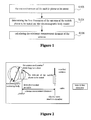
Figure 2 is a schematic diagram of the definition of the antenna measurement radio communication link and the minimum measurement distance of a mobile phone antenna; -
Figure 3 is a schematic diagram of determining electromagnetic scattering dimension of a mobile phone antenna to be tested and an electromagnetic scattering body in a predetermined spatial area; -
Figure 4 is a schematic diagram of the result of the antenna measurement distance determined (electromagnetic body model 1: model of human head); -
Figure 5 is a schematic diagram of the result of the antenna measurement distance determined (electromagnetic body model 2: model of human head and shoulder). - In the present invention, the mobile phone to be tested and the antenna thereof are processed according to the Black-box, that is, detailed process of the mobile phone to be tested and the antenna thereof will be not involved. Preferred embodiments of the present invention will be illustrated in combination with the accompanying drawings in details as follows. If not conflict, the embodiments and the technical features of the embodiments can be combined with each other.
-
Figure 1 is a flowchart of the method for determining the minimum measurement distance of a mobile phone antenna according to the embodiments of the invention;Figure 2 is a schematic diagram of the definition of the antenna measurement radio communication link and the minimum measurement distance of a mobile phone antenna; andFigure 3 is a schematic diagram of determining electromagnetic scattering dimension of a mobile phone antenna to be tested and an electromagnetic scattering body in a predetermined spatial area. The procedure ofFigure 3 will be described in details in combination withfigures 1 and 2 . - As shown in
figure 1 , the method for determining the antenna minimum measurement distance of a wireless mobile terminal comprises the following steps: - Step 102, establishing an antenna testing environment of a wireless mobile terminal to be tested. Preferably, the following steps are included: putting the wireless mobile terminal under tested and the antenna thereof and a model of the electromagnetic scattering body on a test platform in a microwave anechoic chamber, and connecting with a simulator through cable; connecting the radio frequency port of a standard antenna with the simulator through radio frequency cable; configuring parameters of the simulator; setting the back light of the wireless mobile terminal to be tested to the closed state or the darkest state, and setting the wireless mobile terminal to be tested to the standby state.
- Wherein, preferably, the electromagnetic scattering dimension is the minimum diameter of a virtual spherical surface encircling both the wireless mobile terminal under tested and the electromagnetic scattering body in the predetermined spatial area; preferably, the cable is low-loss cables; and the radio frequency cable is low-power radio frequency cable; and the simulator is preferably a network simulator. The step of configuring parameters of the simulator can be achieved by configuring the voice service to be a fixed voice service with a decided voice traffic. The model mensioned above comprises the mobile phone to be tested and the antenna thereof and an electromagnetic body model.
- Preferably, the predetermined spatial area refers to a spatial area of a spherical surface determined with a diameter from 0.01λ to 0.1λ, wherein λ is the wavelength of carrier wave.
- The above process will be described in details as follows, comprising:
- Step 1: putting the mobile phone under tested and the antenna thereof and the model of a human head in a microwave anechoic chamber, which is electromagnetically shielded from external electromagnetic waves, and connecting with the network simulator via low-loss cables;
-
Step 2, putting the mobile phone to be tested (including its antenna) on a test platform. Since the test platform here should be a rotary platform providing support for measurement of the mobile phone to be tested, it should not affect the measurement of the mobile phone to be tested. Therefore, the test platform should be a test platform made of materials of low electromagnetic loss; -
Step 3, connecting the radio frequency port of a standard antenna with one end of the low-power radio frequency cable whose loss is known, and connecting the other end of the low-power radio frequency cable with the network simulator as shown infigure 2 . A high frequency choke exterior to the low-power radio frequency cable is set to avoid loss of electromagnetic signals in internal transmission; - Step 4, configuring parameters of the network simulator and configuring the voice service to be a fixed voice service with a decided voice traffic;
- Step 5, setting the back light of the mobile phone to be tested to the closed state or the darkest state; and
- Step 6, setting the mobile phone to be tested to the standby state. In case of a clamshell phone, opening the upper cover to the upmost extend.
- Step 104, determining electromagnetic scattering dimension of the antenna of the mobile terminal to be tested and the electromagnetic scattering body in a predetermined spatial area in the test environment, comprising:
- A, the electromagnetic model refers to the electromagnetic characteristic of the model. Moreover, the spatial geometrical characteristic and dimensional characteristic are consistent with the model object.
- B, the antenna of the mobile phone to be tested and the electromagnetic body model comprise the mobile phone to be tested and the antenna thereof and also the electromagnetic body model (including a human head electromagnetic model, a combined electromagnetic model of a human head electromagnetic model and a neck and shoulder electromagnetic model, or an integral electromagnetic model);
- C, the electromagnetic scattering dimension l refers to the minimum diameter of a spherical surface encircling the mobile phone to be tested and the antenna thereof and the electromagnetic body model.
-
Step 106, calculating the minimum measurement distance of the antenna of the wireless mobile terminal according to the determined electromagnetic scattering dimension, comprising the following steps: calculating a first distance r 1, a second distance r 2 and a third distance r 3 according to electromagnetic scattering dimension; taking the maximum of the first distance, the second distance and the third distance as the minimum measurement distance of the antenna of the wireless mobile terminal, wherein r 1=2l 2/λ, r 2 =3λ, r 3 = 3l, l is the electromagnetic scattering dimension. The above electromagnetic scattering body in the predetermined spatial area is a human body. - The
step 106 is carried out as follows: - a. calculating the measurement distance r 1 (refer to the real lines in
figures 4 and 5 ), r 2 (refer to the dashdotted lines infigures 4 and 5 ), and r 3 according to theparameter 1 obtained, wherein r 1=2l 2/λ, r 2 = 3λ, r 3 = 3l; and - b. alculating the minimum measurement distance r of the antenna, wherein r = max (r 1 , r 2, r 3) , i.e. r is the maximum of r 1, r 2 and r 3.
- Step 106 can also be carried out in another way, comprising the following steps:
- a. calculating the measurement distance r 1 (see the real lines in
figures 4 and 5 ) and r 2 (see the dashdotted lines infigures 4 and 5 ) according to the parameter l obtained, wherein r 1=2l 2/λ , r 2 = 3λ ; and - b. calculating the minimum measurement distance r of the antenna, wherein r is the maximum of r 1 and r 2.
- The measurement results are as shown in
figures 4 and 5 , whereinfigure 4 is a schematic diagram of the result of antenna measurement distance determined (electromagnetic body model 1: model of human head) andfigure 5 is a schematic diagram of the result of antenna measurement distance determined (electromagnetic body model 2: model of human head and shoulder). - As shown in
figure 4 , the broken line shows the measurement result which is obtained without taking the existence of a human head into consideration. The real line shows the measurement result which is obtained when take the existence a human head into consideration. It can be seen from the figure that the dashdotted lines (the bigger one) should be taken as the result in the circs of theelectromagnetic body model 1. - Additionally, in the circs of the electromagnetic model 2 (i.e. an electromagnetic model consisting of human head and shoulder), as shown in
figure 5 , as to the frequency area in the left side of the junction of the upper and lower curves, the value shown by the dashdotted lines should be taken, while as to the frequency area in the right side, the value shown by the real lines should be taken. Wherein the electromagnetic scattering dimension is the minimum diameter of a spherical surface encircling the wireless mobile terminal to be tested and the electromagnetic scattering body in the predetermined spatial area. - According to the present invention, the predetermined spatial area refers to a spherical surface spatial area determined with a diameter from 0.01λ to 0.1λ, wherein λ is the wavelength of carrier wave; cables are low-loss cables; the radio frequency cable is a low-power radio frequency cable; and the simulator is a network simulator.
- In addition, the electromagnetic scattering body in the predetermined spatial area according to the present invention is a human body and the electromagnetic scattering body comprises the head of the user of the wireless mobile terminal and further comprises the shoulder of the user of the wireless mobile terminal.
- It can be seen from above, with the universal method for determining the minimum measurement distance of a mobile phone antenna of the present invention, electromagnetic scattering dimension of the mobile phone antenna and the electromagnetic scattering body in the predetermined spatial area is determined and measured in a simulated network environment in an electric wave anechoic chamber, and parameters of the minimum measurement distance of the mobile phone antenna can be calculated and obtained. The method has low requirement on environment and is easy to be tested and convenient to be carried out.
- According to another embodiment of the present invention, a computer program and a computer program product thereof are provided. Wherein the computer program product comprises instructions for causing a processor to perform the processes illustrated above with refer to
figures 1-5 . - Obviously, one skilled in the art shall understand that various modules and steps above can be realized with general computing devices and can be integrated into one single computing device or distributed within a network consisting of multiple computing devices, and alternatively, the various modules and steps above can be realized with the program codes executable by the computing devices, and thus these program codes can be stored in memory devices so as to be executed by the computing devices, or the various modules and steps above can be formed into individual integrated circuit modules, or a plurality of the modules or steps can be formed into a single integrated circuit module so as to be realized. Therefore, the present invention is not limited to any particular hardware or software combination. It should be understood that alterations of the embodiments are apparent to one skilled in the art and do not depart from the scope and spirit of the present invention.
- The present invention has been shown with reference to the above-described embodiments, and it is not to be limited by the above embodiments. It is understood by those skilled in the art various alterations and changes may be made within the spirit and scope of the invention. All modifications, substitute equivalents or improvements made therein are intended to be embraced in the claims of this invention.
Claims (13)
- A method for determining the antenna minimum measurement distance of a wireless mobile terminal, characterized in, comprising the following steps:step 102, establishing an antenna testing environment of a wireless mobile terminal to be tested;step 104, determining electromagnetic scattering dimension of the antenna of the mobile terminal to be tested and an electromagnetic scattering body in a predetermined spatial area in the test environment; andstep 106, calculating the minimum measurement distance of the antenna of the wireless mobile terminal according to the determined electromagnetic scattering dimension.
- The method according to claim 1, characterized in, the electromagnetic scattering dimension is the minimum diameter of a spherical surface encircling both the wireless mobile terminal under tested and the electromagnetic scattering body in the predetermined spatial area.
- The method according to claim 2, characterized in, the predetermined spatial area refers to a spherical surface spatial area determined with a diameter from 0.01λ to 0.1λ, wherein λ is the wavelength of carrier wave.
- The method according to claim 1, characterized in, the step 102 comprises the following steps:putting the wireless mobile terminal under tested and the antenna thereof, and a model of the electromagnetic scattering body on a test platform in a microwave anechoic chamber and connecting with a simulator through cables;connecting the radio frequency port of a standard antenna with the simulator through a radio frequency cable;configuring parameters of the simulator; andsetting the back light of the wireless mobile terminal to be tested to the closed state or the darkest state, and setting the wireless mobile terminal to be tested to the standby state.
- The method according to claim 4, characterized in, the cables are low-loss cables.
- The method according to claim 4, characterized in, the radio frequency cable is a low-power radio frequency cable.
- The method according to claim 4, characterized in, the simulator is a network simulator.
- The method according to claim 4, characterized in, the step of configuring parameters of the simulator comprises: configuring the voice service to be a fixed voice service with a decided voice traffic.
- The method according to claim 1, characterized in, the step 106 comprises the following steps:calculating a first distance r 1 , a second distance r 2 and a third distance r 3 according to the electromagnetic scattering dimension;taking the maximum of the first distance, the second distance and the third distance as the minimum measurement distance of the antenna of the wireless mobile terminal, wherein r 1 =2l 2/λ, r 2 = 3λ, r 3 = 3l, l is the electromagnetic scattering dimension, and λ is the wavelength of carrier wave.
- The method according to claim 1, characterized in, the step 106 comprises the following steps:calculating a first distance r 1 and a second distance r 2 according to the electromagnetic scattering dimension;taking the maximum of the first distance and the second distance as the minimum measurement distance of the antenna of the wireless mobile terminal, wherein r 1 =2l 2/λ, r 2 = 3λ , l is the electromagnetic scattering dimension, and λ is the wavelength of carrier wave.
- The method according to claim 1, 9 or 10, characterized in, the electromagnetic scattering body in the predetermined spatial area is a human body.
- The method according to claim 11, characterized in, the electromagnetic scattering body comprises the head of the user of the wireless mobile terminal.
- The method according to claim 12, characterized in, the electromagnetic scattering body further comprises the shoulder of the user of the wireless mobile terminal.
Applications Claiming Priority (2)
| Application Number | Priority Date | Filing Date | Title |
|---|---|---|---|
| CNA2006101608753A CN1964547A (en) | 2006-11-30 | 2006-11-30 | A method to determine minimum test distance of antenna |
| PCT/CN2007/001603 WO2008064544A1 (en) | 2006-11-30 | 2007-05-17 | The method for determining the minimum measurement distance of antenna |
Publications (3)
| Publication Number | Publication Date |
|---|---|
| EP2098876A1 true EP2098876A1 (en) | 2009-09-09 |
| EP2098876A4 EP2098876A4 (en) | 2013-10-09 |
| EP2098876B1 EP2098876B1 (en) | 2019-09-04 |
Family
ID=38083376
Family Applications (1)
| Application Number | Title | Priority Date | Filing Date |
|---|---|---|---|
| EP07721176.1A Active EP2098876B1 (en) | 2006-11-30 | 2007-05-17 | The method for determining the minimum measurement distance of antenna |
Country Status (4)
| Country | Link |
|---|---|
| US (1) | US8395556B2 (en) |
| EP (1) | EP2098876B1 (en) |
| CN (2) | CN1964547A (en) |
| WO (1) | WO2008064544A1 (en) |
Families Citing this family (11)
| Publication number | Priority date | Publication date | Assignee | Title |
|---|---|---|---|---|
| CN101819237B (en) * | 2010-04-08 | 2011-12-14 | 中国舰船研究设计中心 | Method for discriminating cavity structure periphery electromagnetic environment strength |
| FR2965931B1 (en) * | 2010-10-08 | 2013-05-03 | Satimo Ind | METHOD AND DEVICE FOR ELECTRONIC TESTING OF AN OBJECT |
| CN102508049A (en) * | 2011-11-22 | 2012-06-20 | 西北工业大学 | Method for testing midfield of antenna on basis of Hankel function extrapolation |
| CN103293393B (en) * | 2012-02-29 | 2017-04-12 | 深圳光启创新技术有限公司 | Compact range generating device |
| CN103293395B (en) * | 2012-02-29 | 2017-04-12 | 深圳光启创新技术有限公司 | Compact range generating device |
| CN103293394B (en) * | 2012-02-29 | 2017-04-05 | 深圳光启创新技术有限公司 | A kind of Compact range generation device |
| CN103293392B (en) * | 2012-02-29 | 2017-04-05 | 深圳光启创新技术有限公司 | A kind of Compact range generation device |
| CN102788908B (en) * | 2012-07-24 | 2014-12-10 | 中国舰船研究设计中心 | Method for predicting horizontal electromagnetic scattering mean of ship loaded with cylindrical whip antenna |
| CN103245841B (en) * | 2013-04-28 | 2015-07-01 | 西北工业大学 | Antenna directional pattern testing method based on spherical surface near-field scanning extrapolation |
| CN107966616B (en) * | 2016-10-19 | 2021-06-11 | 郑州宇通客车股份有限公司 | Electric vehicle electromagnetic field emission intensity testing method based on vehicle body three-dimensional model |
| US11698401B1 (en) * | 2022-02-04 | 2023-07-11 | Rohde & Schwarz Gmbh & Co. Kg | Method of simulating an effect of interactions between a device under test and a scattering object and hybrid OTA test system |
Citations (1)
| Publication number | Priority date | Publication date | Assignee | Title |
|---|---|---|---|---|
| EP1598966A2 (en) * | 2004-05-12 | 2005-11-23 | NTT DoCoMo, Inc. | Radiation power measurement and antenna weights determination based on a test wave |
Family Cites Families (14)
| Publication number | Priority date | Publication date | Assignee | Title |
|---|---|---|---|---|
| FR2797327B1 (en) * | 1999-08-03 | 2001-11-09 | France Telecom | METHOD AND APPARATUS FOR MEASURING NEAR FIELD RADIOELECTRIC RADIATION |
| US6329953B1 (en) * | 2000-09-29 | 2001-12-11 | Rangestar Wireless | Method and system for rating antenna performance |
| GB2373374B (en) * | 2001-03-15 | 2004-03-17 | Agilent Technologies Inc | Novel fiber optic transceiver module |
| US7035594B2 (en) * | 2001-07-02 | 2006-04-25 | Qualcomm Inc. | Method and apparatus for testing and evaluating wireless communication devices |
| EP1326070B1 (en) * | 2001-08-08 | 2013-07-10 | NTT DoCoMo, Inc. | Absorption power measuring device |
| US6540414B1 (en) * | 2001-10-05 | 2003-04-01 | International Business Machines Corporation | Integrated optical coupler and housing arrangement |
| KR100449436B1 (en) * | 2001-10-31 | 2004-09-21 | 주식회사 어필텔레콤 | Antenna device of wireless phone |
| CN1209635C (en) * | 2002-12-03 | 2005-07-06 | 智邦科技股份有限公司 | Antenna testing system |
| TWI246614B (en) * | 2003-06-20 | 2006-01-01 | Ind Tech Res Inst | Low-density wavelength division multiplexing light transmission module |
| FR2859023B1 (en) * | 2003-08-18 | 2005-12-23 | Satimo Sa | ANECHOIC CHAMBER WITH DIRECT OBSERVATION OF THE ELECTROMAGNETIC BEHAVIOR OF A TOOL TO BE INVESTIGATED |
| CN1308696C (en) * | 2003-11-29 | 2007-04-04 | 富士康(昆山)电脑接插件有限公司 | Antenna testing method |
| US7477877B2 (en) * | 2004-02-11 | 2009-01-13 | Sony Ericsson Mobile Communications Ab | GSM radiated sensitivity measurement technique |
| US7102562B2 (en) * | 2004-03-22 | 2006-09-05 | Motorola, Inc. | Radio frequency anechoic chamber with improved test stand |
| US7178996B2 (en) * | 2004-04-09 | 2007-02-20 | Jds Uniphase Corporation | High density optical transceiver |
-
2006
- 2006-11-30 CN CNA2006101608753A patent/CN1964547A/en active Pending
-
2007
- 2007-05-17 WO PCT/CN2007/001603 patent/WO2008064544A1/en active Application Filing
- 2007-05-17 US US12/516,345 patent/US8395556B2/en active Active
- 2007-05-17 EP EP07721176.1A patent/EP2098876B1/en active Active
- 2007-11-16 CN CN2007101697569A patent/CN101231316B/en active Active
Patent Citations (1)
| Publication number | Priority date | Publication date | Assignee | Title |
|---|---|---|---|---|
| EP1598966A2 (en) * | 2004-05-12 | 2005-11-23 | NTT DoCoMo, Inc. | Radiation power measurement and antenna weights determination based on a test wave |
Non-Patent Citations (5)
| Title |
|---|
| "3rd Generation Partnership Project; Technical Specification Group Radio Access Network; Measurements of radio performances for UMTS terminals in speech mode (Release 7)", 3GPP STANDARD; 3GPP TR 25.914, 3RD GENERATION PARTNERSHIP PROJECT (3GPP), MOBILE COMPETENCE CENTRE ; 650, ROUTE DES LUCIOLES ; F-06921 SOPHIA-ANTIPOLIS CEDEX ; FRANCE, no. V7.0.0, 1 June 2006 (2006-06-01), pages 1-67, XP050369346, * |
| "prEN50xyyBTSBasicvUAPUK300401", ETSI DRAFT; PREN_50XYY_BTS_BASIC_VUAP_UK300401, EUROPEAN TELECOMMUNICATIONS STANDARDS INSTITUTE (ETSI), 650, ROUTE DES LUCIOLES ; F-06921 SOPHIA-ANTIPOLIS ; FRANCE, vol. Safety, 14 June 2001 (2001-06-14), pages 1-102, XP014103269, [retrieved on 2001-06-14] * |
| BENOT DERAT ET AL: "Various Optimization Problems of Electromagnetic Power Absorption in Homogeneous and Heterogeneous Phantoms", IEEE TRANSACTIONS ON ELECTROMAGNETIC COMPATIBILITY, IEEE SERVICE CENTER, NEW YORK, NY, US, vol. 48, no. 4, 1 November 2006 (2006-11-01), pages 641-647, XP011150749, ISSN: 0018-9375, DOI: 10.1109/TEMC.2006.884619 * |
| N/A: "Traceable Ota Performance Testing Proposal ; 11-06-0131-00-000t-traceable-ota-performan ce-testing-proposal", IEEE DRAFT; 11-06-0131-00-000T-TRACEABLE-OTA-PERFORMAN CE-TESTING-PROPOSAL, IEEE-SA MENTOR, PISCATAWAY, NJ USA, vol. 802.11T, 19 January 2006 (2006-01-19) , pages 1-20, XP017687852, [retrieved on 2006-01-19] * |
| See also references of WO2008064544A1 * |
Also Published As
| Publication number | Publication date |
|---|---|
| EP2098876B1 (en) | 2019-09-04 |
| CN1964547A (en) | 2007-05-16 |
| US8395556B2 (en) | 2013-03-12 |
| CN101231316B (en) | 2012-12-05 |
| US20100109956A1 (en) | 2010-05-06 |
| EP2098876A4 (en) | 2013-10-09 |
| WO2008064544A1 (en) | 2008-06-05 |
| CN101231316A (en) | 2008-07-30 |
Similar Documents
| Publication | Publication Date | Title |
|---|---|---|
| EP2098876B1 (en) | The method for determining the minimum measurement distance of antenna | |
| US8513963B2 (en) | Radio frequency testing apparatus | |
| US20150226777A1 (en) | Antenna testing device and method | |
| Quijano et al. | Optimization of a compact frequency-and environment-reconfigurable antenna | |
| JP2022506002A (en) | Near-field antenna for remote radio control of antenna array | |
| Kurup et al. | Path loss model for in-body communication in homogeneous human muscle tissue | |
| CN110514907B (en) | Air transmission measuring system for wireless communication device | |
| CN109041096B (en) | Radio frequency circuit simulation method and related device | |
| CN101106792A (en) | Parameter measurement method for wireless video terminal | |
| CN207543102U (en) | Mobile terminal | |
| KR20210020667A (en) | Printed circuit board and apparatus for comprising printed circuit board embedded filter with via group pattern | |
| CN113824613B (en) | Network reliability test method, test system and storage medium | |
| CN111505395B (en) | Processing method for giving consideration to OTA and SAR tests | |
| CN109005555B (en) | Method for testing radio frequency performance under LTE network system | |
| Amin-Zadeh et al. | Inspecting safety level of bluetooth headset radiation in the vicinity of human head: A numerical study | |
| CN218727657U (en) | Transverse electric wave cell | |
| Laghari et al. | Modeling and analysis of 5G antenna radiation effect on human head by calculating specific absorption rate (SAR) using adult brain model | |
| JP3608287B2 (en) | Shielding box with built-in directional antenna | |
| Collins | Practical application of small antennas in hardware platforms | |
| Visvesvaran et al. | Design and Implementation of Various Antenna for Smart Watch Applications | |
| Son | Feeding point determination for PIFA type mobile phone handset internal antenna | |
| CN112019281B (en) | Audio breakthrough performance testing method, device, equipment and storage medium | |
| Rodriguez-Duarte et al. | Antenna for In-Band Full-Duplex Wireless Communications | |
| Helmius | Method for evaluating vehicular antennas in reverberation chambers | |
| Chen et al. | A Novel Approach for Mobile Device Design: GA-Based Distributed Optimization to Comply with OTA, SAR, and HAC Standards |
Legal Events
| Date | Code | Title | Description |
|---|---|---|---|
| PUAI | Public reference made under article 153(3) epc to a published international application that has entered the european phase |
Free format text: ORIGINAL CODE: 0009012 |
|
| 17P | Request for examination filed |
Effective date: 20090529 |
|
| AK | Designated contracting states |
Kind code of ref document: A1 Designated state(s): AT BE BG CH CY CZ DE DK EE ES FI FR GB GR HU IE IS IT LI LT LU LV MC MT NL PL PT RO SE SI SK TR |
|
| DAX | Request for extension of the european patent (deleted) | ||
| A4 | Supplementary search report drawn up and despatched |
Effective date: 20130910 |
|
| RIC1 | Information provided on ipc code assigned before grant |
Ipc: G01R 29/10 20060101AFI20130904BHEP Ipc: G01R 29/08 20060101ALI20130904BHEP |
|
| STAA | Information on the status of an ep patent application or granted ep patent |
Free format text: STATUS: EXAMINATION IS IN PROGRESS |
|
| 17Q | First examination report despatched |
Effective date: 20180130 |
|
| GRAP | Despatch of communication of intention to grant a patent |
Free format text: ORIGINAL CODE: EPIDOSNIGR1 |
|
| STAA | Information on the status of an ep patent application or granted ep patent |
Free format text: STATUS: GRANT OF PATENT IS INTENDED |
|
| INTG | Intention to grant announced |
Effective date: 20190327 |
|
| GRAS | Grant fee paid |
Free format text: ORIGINAL CODE: EPIDOSNIGR3 |
|
| GRAA | (expected) grant |
Free format text: ORIGINAL CODE: 0009210 |
|
| STAA | Information on the status of an ep patent application or granted ep patent |
Free format text: STATUS: THE PATENT HAS BEEN GRANTED |
|
| AK | Designated contracting states |
Kind code of ref document: B1 Designated state(s): AT BE BG CH CY CZ DE DK EE ES FI FR GB GR HU IE IS IT LI LT LU LV MC MT NL PL PT RO SE SI SK TR |
|
| REG | Reference to a national code |
Ref country code: GB Ref legal event code: FG4D |
|
| REG | Reference to a national code |
Ref country code: CH Ref legal event code: EP |
|
| REG | Reference to a national code |
Ref country code: AT Ref legal event code: REF Ref document number: 1176110 Country of ref document: AT Kind code of ref document: T Effective date: 20190915 |
|
| REG | Reference to a national code |
Ref country code: DE Ref legal event code: R096 Ref document number: 602007059154 Country of ref document: DE |
|
| REG | Reference to a national code |
Ref country code: IE Ref legal event code: FG4D |
|
| REG | Reference to a national code |
Ref country code: NL Ref legal event code: MP Effective date: 20190904 |
|
| REG | Reference to a national code |
Ref country code: LT Ref legal event code: MG4D |
|
| PG25 | Lapsed in a contracting state [announced via postgrant information from national office to epo] |
Ref country code: LT Free format text: LAPSE BECAUSE OF FAILURE TO SUBMIT A TRANSLATION OF THE DESCRIPTION OR TO PAY THE FEE WITHIN THE PRESCRIBED TIME-LIMIT Effective date: 20190904 Ref country code: FI Free format text: LAPSE BECAUSE OF FAILURE TO SUBMIT A TRANSLATION OF THE DESCRIPTION OR TO PAY THE FEE WITHIN THE PRESCRIBED TIME-LIMIT Effective date: 20190904 Ref country code: BG Free format text: LAPSE BECAUSE OF FAILURE TO SUBMIT A TRANSLATION OF THE DESCRIPTION OR TO PAY THE FEE WITHIN THE PRESCRIBED TIME-LIMIT Effective date: 20191204 Ref country code: SE Free format text: LAPSE BECAUSE OF FAILURE TO SUBMIT A TRANSLATION OF THE DESCRIPTION OR TO PAY THE FEE WITHIN THE PRESCRIBED TIME-LIMIT Effective date: 20190904 |
|
| PG25 | Lapsed in a contracting state [announced via postgrant information from national office to epo] |
Ref country code: LV Free format text: LAPSE BECAUSE OF FAILURE TO SUBMIT A TRANSLATION OF THE DESCRIPTION OR TO PAY THE FEE WITHIN THE PRESCRIBED TIME-LIMIT Effective date: 20190904 Ref country code: GR Free format text: LAPSE BECAUSE OF FAILURE TO SUBMIT A TRANSLATION OF THE DESCRIPTION OR TO PAY THE FEE WITHIN THE PRESCRIBED TIME-LIMIT Effective date: 20191205 Ref country code: ES Free format text: LAPSE BECAUSE OF FAILURE TO SUBMIT A TRANSLATION OF THE DESCRIPTION OR TO PAY THE FEE WITHIN THE PRESCRIBED TIME-LIMIT Effective date: 20190904 |
|
| REG | Reference to a national code |
Ref country code: AT Ref legal event code: MK05 Ref document number: 1176110 Country of ref document: AT Kind code of ref document: T Effective date: 20190904 |
|
| PG25 | Lapsed in a contracting state [announced via postgrant information from national office to epo] |
Ref country code: PL Free format text: LAPSE BECAUSE OF FAILURE TO SUBMIT A TRANSLATION OF THE DESCRIPTION OR TO PAY THE FEE WITHIN THE PRESCRIBED TIME-LIMIT Effective date: 20190904 Ref country code: NL Free format text: LAPSE BECAUSE OF FAILURE TO SUBMIT A TRANSLATION OF THE DESCRIPTION OR TO PAY THE FEE WITHIN THE PRESCRIBED TIME-LIMIT Effective date: 20190904 Ref country code: EE Free format text: LAPSE BECAUSE OF FAILURE TO SUBMIT A TRANSLATION OF THE DESCRIPTION OR TO PAY THE FEE WITHIN THE PRESCRIBED TIME-LIMIT Effective date: 20190904 Ref country code: AT Free format text: LAPSE BECAUSE OF FAILURE TO SUBMIT A TRANSLATION OF THE DESCRIPTION OR TO PAY THE FEE WITHIN THE PRESCRIBED TIME-LIMIT Effective date: 20190904 Ref country code: IT Free format text: LAPSE BECAUSE OF FAILURE TO SUBMIT A TRANSLATION OF THE DESCRIPTION OR TO PAY THE FEE WITHIN THE PRESCRIBED TIME-LIMIT Effective date: 20190904 Ref country code: PT Free format text: LAPSE BECAUSE OF FAILURE TO SUBMIT A TRANSLATION OF THE DESCRIPTION OR TO PAY THE FEE WITHIN THE PRESCRIBED TIME-LIMIT Effective date: 20200106 Ref country code: RO Free format text: LAPSE BECAUSE OF FAILURE TO SUBMIT A TRANSLATION OF THE DESCRIPTION OR TO PAY THE FEE WITHIN THE PRESCRIBED TIME-LIMIT Effective date: 20190904 |
|
| PG25 | Lapsed in a contracting state [announced via postgrant information from national office to epo] |
Ref country code: CZ Free format text: LAPSE BECAUSE OF FAILURE TO SUBMIT A TRANSLATION OF THE DESCRIPTION OR TO PAY THE FEE WITHIN THE PRESCRIBED TIME-LIMIT Effective date: 20190904 Ref country code: SK Free format text: LAPSE BECAUSE OF FAILURE TO SUBMIT A TRANSLATION OF THE DESCRIPTION OR TO PAY THE FEE WITHIN THE PRESCRIBED TIME-LIMIT Effective date: 20190904 Ref country code: IS Free format text: LAPSE BECAUSE OF FAILURE TO SUBMIT A TRANSLATION OF THE DESCRIPTION OR TO PAY THE FEE WITHIN THE PRESCRIBED TIME-LIMIT Effective date: 20200224 |
|
| REG | Reference to a national code |
Ref country code: DE Ref legal event code: R097 Ref document number: 602007059154 Country of ref document: DE |
|
| PLBE | No opposition filed within time limit |
Free format text: ORIGINAL CODE: 0009261 |
|
| STAA | Information on the status of an ep patent application or granted ep patent |
Free format text: STATUS: NO OPPOSITION FILED WITHIN TIME LIMIT |
|
| PG2D | Information on lapse in contracting state deleted |
Ref country code: IS |
|
| PG25 | Lapsed in a contracting state [announced via postgrant information from national office to epo] |
Ref country code: DK Free format text: LAPSE BECAUSE OF FAILURE TO SUBMIT A TRANSLATION OF THE DESCRIPTION OR TO PAY THE FEE WITHIN THE PRESCRIBED TIME-LIMIT Effective date: 20190904 Ref country code: IS Free format text: LAPSE BECAUSE OF FAILURE TO SUBMIT A TRANSLATION OF THE DESCRIPTION OR TO PAY THE FEE WITHIN THE PRESCRIBED TIME-LIMIT Effective date: 20200105 |
|
| 26N | No opposition filed |
Effective date: 20200605 |
|
| PG25 | Lapsed in a contracting state [announced via postgrant information from national office to epo] |
Ref country code: SI Free format text: LAPSE BECAUSE OF FAILURE TO SUBMIT A TRANSLATION OF THE DESCRIPTION OR TO PAY THE FEE WITHIN THE PRESCRIBED TIME-LIMIT Effective date: 20190904 |
|
| PG25 | Lapsed in a contracting state [announced via postgrant information from national office to epo] |
Ref country code: CH Free format text: LAPSE BECAUSE OF NON-PAYMENT OF DUE FEES Effective date: 20200531 Ref country code: LI Free format text: LAPSE BECAUSE OF NON-PAYMENT OF DUE FEES Effective date: 20200531 Ref country code: MC Free format text: LAPSE BECAUSE OF FAILURE TO SUBMIT A TRANSLATION OF THE DESCRIPTION OR TO PAY THE FEE WITHIN THE PRESCRIBED TIME-LIMIT Effective date: 20190904 |
|
| REG | Reference to a national code |
Ref country code: BE Ref legal event code: MM Effective date: 20200531 |
|
| PG25 | Lapsed in a contracting state [announced via postgrant information from national office to epo] |
Ref country code: LU Free format text: LAPSE BECAUSE OF NON-PAYMENT OF DUE FEES Effective date: 20200517 |
|
| PG25 | Lapsed in a contracting state [announced via postgrant information from national office to epo] |
Ref country code: IE Free format text: LAPSE BECAUSE OF NON-PAYMENT OF DUE FEES Effective date: 20200517 |
|
| PG25 | Lapsed in a contracting state [announced via postgrant information from national office to epo] |
Ref country code: BE Free format text: LAPSE BECAUSE OF NON-PAYMENT OF DUE FEES Effective date: 20200531 |
|
| PG25 | Lapsed in a contracting state [announced via postgrant information from national office to epo] |
Ref country code: TR Free format text: LAPSE BECAUSE OF FAILURE TO SUBMIT A TRANSLATION OF THE DESCRIPTION OR TO PAY THE FEE WITHIN THE PRESCRIBED TIME-LIMIT Effective date: 20190904 Ref country code: MT Free format text: LAPSE BECAUSE OF FAILURE TO SUBMIT A TRANSLATION OF THE DESCRIPTION OR TO PAY THE FEE WITHIN THE PRESCRIBED TIME-LIMIT Effective date: 20190904 Ref country code: CY Free format text: LAPSE BECAUSE OF FAILURE TO SUBMIT A TRANSLATION OF THE DESCRIPTION OR TO PAY THE FEE WITHIN THE PRESCRIBED TIME-LIMIT Effective date: 20190904 |
|
| PGFP | Annual fee paid to national office [announced via postgrant information from national office to epo] |
Ref country code: FR Payment date: 20230309 Year of fee payment: 17 |
|
| PGFP | Annual fee paid to national office [announced via postgrant information from national office to epo] |
Ref country code: GB Payment date: 20230323 Year of fee payment: 17 |
|
| P01 | Opt-out of the competence of the unified patent court (upc) registered |
Effective date: 20230530 |
|
| PGFP | Annual fee paid to national office [announced via postgrant information from national office to epo] |
Ref country code: DE Payment date: 20230321 Year of fee payment: 17 |