EP2098677A1 - Method of controlling a device for closing and opening a door with wired control - Google Patents
Method of controlling a device for closing and opening a door with wired control Download PDFInfo
- Publication number
- EP2098677A1 EP2098677A1 EP09370004A EP09370004A EP2098677A1 EP 2098677 A1 EP2098677 A1 EP 2098677A1 EP 09370004 A EP09370004 A EP 09370004A EP 09370004 A EP09370004 A EP 09370004A EP 2098677 A1 EP2098677 A1 EP 2098677A1
- Authority
- EP
- European Patent Office
- Prior art keywords
- limit switches
- movable member
- mode
- switch
- electronic circuit
- Prior art date
- Legal status (The legal status is an assumption and is not a legal conclusion. Google has not performed a legal analysis and makes no representation as to the accuracy of the status listed.)
- Granted
Links
Images


Classifications
-
- E—FIXED CONSTRUCTIONS
- E06—DOORS, WINDOWS, SHUTTERS, OR ROLLER BLINDS IN GENERAL; LADDERS
- E06B—FIXED OR MOVABLE CLOSURES FOR OPENINGS IN BUILDINGS, VEHICLES, FENCES OR LIKE ENCLOSURES IN GENERAL, e.g. DOORS, WINDOWS, BLINDS, GATES
- E06B9/00—Screening or protective devices for wall or similar openings, with or without operating or securing mechanisms; Closures of similar construction
- E06B9/56—Operating, guiding or securing devices or arrangements for roll-type closures; Spring drums; Tape drums; Counterweighting arrangements therefor
- E06B9/68—Operating devices or mechanisms, e.g. with electric drive
-
- G—PHYSICS
- G05—CONTROLLING; REGULATING
- G05B—CONTROL OR REGULATING SYSTEMS IN GENERAL; FUNCTIONAL ELEMENTS OF SUCH SYSTEMS; MONITORING OR TESTING ARRANGEMENTS FOR SUCH SYSTEMS OR ELEMENTS
- G05B19/00—Programme-control systems
- G05B19/02—Programme-control systems electric
- G05B19/42—Recording and playback systems, i.e. in which the programme is recorded from a cycle of operations, e.g. the cycle of operations being manually controlled, after which this record is played back on the same machine
-
- E—FIXED CONSTRUCTIONS
- E05—LOCKS; KEYS; WINDOW OR DOOR FITTINGS; SAFES
- E05Y—INDEXING SCHEME RELATING TO HINGES OR OTHER SUSPENSION DEVICES FOR DOORS, WINDOWS OR WINGS AND DEVICES FOR MOVING WINGS INTO OPEN OR CLOSED POSITION, CHECKS FOR WINGS AND WING FITTINGS NOT OTHERWISE PROVIDED FOR, CONCERNED WITH THE FUNCTIONING OF THE WING
- E05Y2400/00—Electronic control; Power supply; Power or signal transmission; User interfaces
- E05Y2400/10—Electronic control
- E05Y2400/30—Electronic control of motors
- E05Y2400/32—Position control, detection or monitoring
- E05Y2400/334—Position control, detection or monitoring by using pulse generators
- E05Y2400/34—Pulse count limit setting
-
- E—FIXED CONSTRUCTIONS
- E05—LOCKS; KEYS; WINDOW OR DOOR FITTINGS; SAFES
- E05Y—INDEXING SCHEME RELATING TO HINGES OR OTHER SUSPENSION DEVICES FOR DOORS, WINDOWS OR WINGS AND DEVICES FOR MOVING WINGS INTO OPEN OR CLOSED POSITION, CHECKS FOR WINGS AND WING FITTINGS NOT OTHERWISE PROVIDED FOR, CONCERNED WITH THE FUNCTIONING OF THE WING
- E05Y2800/00—Details, accessories and auxiliary operations not otherwise provided for
-
- E—FIXED CONSTRUCTIONS
- E06—DOORS, WINDOWS, SHUTTERS, OR ROLLER BLINDS IN GENERAL; LADDERS
- E06B—FIXED OR MOVABLE CLOSURES FOR OPENINGS IN BUILDINGS, VEHICLES, FENCES OR LIKE ENCLOSURES IN GENERAL, e.g. DOORS, WINDOWS, BLINDS, GATES
- E06B9/00—Screening or protective devices for wall or similar openings, with or without operating or securing mechanisms; Closures of similar construction
- E06B9/56—Operating, guiding or securing devices or arrangements for roll-type closures; Spring drums; Tape drums; Counterweighting arrangements therefor
- E06B9/68—Operating devices or mechanisms, e.g. with electric drive
- E06B2009/6809—Control
- E06B2009/6818—Control using sensors
- E06B2009/6836—Control using sensors sensing obstacle
-
- E—FIXED CONSTRUCTIONS
- E06—DOORS, WINDOWS, SHUTTERS, OR ROLLER BLINDS IN GENERAL; LADDERS
- E06B—FIXED OR MOVABLE CLOSURES FOR OPENINGS IN BUILDINGS, VEHICLES, FENCES OR LIKE ENCLOSURES IN GENERAL, e.g. DOORS, WINDOWS, BLINDS, GATES
- E06B9/00—Screening or protective devices for wall or similar openings, with or without operating or securing mechanisms; Closures of similar construction
- E06B9/56—Operating, guiding or securing devices or arrangements for roll-type closures; Spring drums; Tape drums; Counterweighting arrangements therefor
- E06B9/68—Operating devices or mechanisms, e.g. with electric drive
- E06B2009/6809—Control
- E06B2009/6818—Control using sensors
- E06B2009/6845—Control using sensors sensing position
-
- G—PHYSICS
- G05—CONTROLLING; REGULATING
- G05B—CONTROL OR REGULATING SYSTEMS IN GENERAL; FUNCTIONAL ELEMENTS OF SUCH SYSTEMS; MONITORING OR TESTING ARRANGEMENTS FOR SUCH SYSTEMS OR ELEMENTS
- G05B2219/00—Program-control systems
- G05B2219/30—Nc systems
- G05B2219/36—Nc in input of data, input key till input tape
- G05B2219/36463—Manual switch to drive motor to wanted position, store, memorize position
-
- G—PHYSICS
- G05—CONTROLLING; REGULATING
- G05B—CONTROL OR REGULATING SYSTEMS IN GENERAL; FUNCTIONAL ELEMENTS OF SUCH SYSTEMS; MONITORING OR TESTING ARRANGEMENTS FOR SUCH SYSTEMS OR ELEMENTS
- G05B2219/00—Program-control systems
- G05B2219/30—Nc systems
- G05B2219/36—Nc in input of data, input key till input tape
- G05B2219/36464—Position, teach, store extreme, full open, closed positions
-
- G—PHYSICS
- G05—CONTROLLING; REGULATING
- G05B—CONTROL OR REGULATING SYSTEMS IN GENERAL; FUNCTIONAL ELEMENTS OF SUCH SYSTEMS; MONITORING OR TESTING ARRANGEMENTS FOR SUCH SYSTEMS OR ELEMENTS
- G05B2219/00—Program-control systems
- G05B2219/30—Nc systems
- G05B2219/45—Nc applications
- G05B2219/45015—Roller blind, shutter
Landscapes
- Engineering & Computer Science (AREA)
- Structural Engineering (AREA)
- Architecture (AREA)
- Civil Engineering (AREA)
- Physics & Mathematics (AREA)
- General Physics & Mathematics (AREA)
- Automation & Control Theory (AREA)
- Operating, Guiding And Securing Of Roll- Type Closing Members (AREA)
- Power-Operated Mechanisms For Wings (AREA)
Abstract
Description
L'invention concerne un procédé de commande d'un dispositif de fermeture et d'ouverture d'un ouvrant à commande filaire. L'invention concerne également un dispositif d'ouverture et de fermeture à commande filaire, tel que notamment un volet roulant, ainsi qu'un moteur polyvalent à commande filaire en tant que tel.The invention relates to a method of controlling a device for closing and opening a wired opening. The invention also relates to a wired control opening and closing device, such as in particular a roller shutter, and a wired control multi-purpose motor as such.
Dans le domaine des volets roulants, il est connu des moteurs à gestion électronique des fins de course. On entend ici par moteur à gestion électronique, un moteur au sens large, comprenant une partie mécanique avec d'une part le moteur en soi, notamment le stator et le rotor, voire un réducteur, et d'autre part l'électronique de commande avec une carte électronique et un codeur angulaire, par exemple du type magnétique ou optique, pour la détection du déplacement angulaire du rotor.In the field of roller shutters, it is known engines with electronic management of the limit switches. Here is meant by electronically controlled motor, a motor in the broad sense, comprising a mechanical part with on the one hand the motor itself, including the stator and the rotor, or a gearbox, and secondly the control electronics with an electronic card and an angular encoder, for example of the magnetic or optical type, for detecting the angular displacement of the rotor.
Ce type de moteur présente un mode de programmation des fins de course au cours duquel les fins de course peuvent être enregistrées et un mode normal d'actionnement au cours duquel la carte électronique coupe l'alimentation des bobinages du moteur lorsque les fins de course sont approchées, voire atteintes, par l'organe mobile.This type of motor has a mode of programming of the limit switches during which the limit switches can be recorded and a normal mode of operation during which the electronic card cuts the power supply of the motor windings when the limit switches are approached or even reached by the movable member.
Actuellement, trois familles de moteur à gestion électronique des fins de course existent sur le marché, à savoir des moteurs à fins de course automatiques, les moteurs à fins de course réglables et des moteurs polyvalents.Currently, three electronically controlled engine families of end positions exist on the market, namely, automatic stroke motors, adjustable stroke motors and multipurpose engines.
Les moteurs à fins de course automatiques permettent un apprentissage automatique des fins de course au cours duquel les fins de course sont repérées par la détection et la reconnaissance automatique de butées physiques, haute et basse. Pour ce faire, la variation d'un paramètre du moteur, telle que par exemple la vitesse du rotor peut être interprétée par l'électronique de commande comme la présence d'un obstacle.The automatic stroke motors allow automatic learning of the limit switches during which the limit switches are identified by the detection and automatic recognition of physical stops, high and low. To do this, the variation of a parameter of the motor, such as for example the speed of the rotor can be interpreted by the control electronics as the presence of an obstacle.
Pour permettre ce mode d'apprentissage automatique des fins de course, le volet roulant doit toutefois nécessairement être équipé de deux butées physiques, haute et basse. Le domaine d'application de ce type de moteur à fins de course automatiques est ainsi concentré sur les applications coffre/PVC dont l'assemblage et la pose sont mieux maîtrisés.To allow this automatic learning mode of the limit switches, the shutter must necessarily be equipped with two physical stops, high and low. The field of application of this type of automatic stroke engine is thus focused on the applications chest / PVC whose assembly and installation are better controlled.
Généralement, les butées mécaniques ou physiques sont constituées, d'une part, pour la butée haute, par deux arrêts du tablier de volet roulant, aptes à engager avec la sous face du coffre de volet roulant, en fin de course haute, et d'autre part, pour la butée basse, par la maçonnerie inférieure de l'ouverture.Generally, the mechanical or physical stops are constituted, on the one hand, for the upper stop, by two stops of the rolling shutter apron, able to engage with the underside of the roller shutter box, at the end of high stroke, and on the other hand, for the lower stop, by the lower masonry of the opening.
De plus, afin de pouvoir mettre en oeuvre la technique de repérage des fins de course, le volet roulant doit être équipé d'un dispositif de verrouillage entre la dernière lame supérieure du tablier et le tambour d'enroulement. Ce type de dispositif existe sous plusieurs formes et permet généralement d'interdire tout relevage frauduleux du tablier en butée basse en créant une liaison rigide entre le tambour et le tablier dans une zone où le tablier n'est pas guidé par les coulisses de volet roulant.In addition, in order to be able to implement the technique of marking the limit switches, the shutter must be equipped with a locking device between the last upper blade of the deck and the winding drum. This type of device exists in several forms and generally allows to prohibit any fraudulent lifting of the abutment abutment by creating a rigid connection between the drum and the deck in an area where the deck is not guided by the rolling shutter slides .
Aussi, si le volet roulant ne dispose pas de butées ou si elles sont trop légères (déformations excessives de la surface du coffre), si des frottements sont trop importants, s'il y a des points durs, des lames en trop, ou encore un tassement insuffisant du tablier, le moteur à fins de course automatiques devient presque inutilisable et les solutions de dépannage peu nombreuses.Also, if the shutter does not have stops or if they are too light (excessive deformations of the surface of the box), if friction is too important, if there are hard points, blades too, or Insufficient settlement of the deck, the automatic stroke engine becomes almost unusable and troubleshooting solutions are few.
Les moteurs à fins de course réglables, contrairement aux moteurs à fins de course automatiques, ne permettent pas un apprentissage automatique des fins de course. En revanche, ils sont plus universels et tolérant avec le produit porteur notamment le volet roulant. Ces moteurs possèdent ainsi un domaine d'application plus large et peuvent être utilisés pour tout type de volet roulant, y compris les portes de garage ainsi que dans le domaine des stores. Ils sont particulièrement sûrs mais sont toutefois pénalisés par l'obligation d'utiliser préalablement un outil d'apprentissage pour la programmation des fins de course. Lors de cette programmation, l'utilisateur doit notamment déplacer l'organe mobile jusqu'à la position de fin de course désirée, pour permettre l'enregistrement de la position des fins de course.Adjustable stroke motors, unlike automatic limit switches, do not allow automatic learning of end positions. On the other hand, they are more universal and tolerant with the carrier product including the shutter. These motors thus have a wider application area and can be used for all types of shutters, including garage doors as well as in the area of blinds. They are particularly safe but are penalized by the obligation to use a learning tool beforehand for the programming of the limit switches. During this programming, the user must in particular move the movable member to the desired end position, to allow the recording of the position of the limit switches.
Enfin, les moteurs dits polyvalents sont des moteurs à gestion électronique des fins de course qui peuvent être configurés, soit en mode de fins de course automatiques, soit en mode de fins de course réglables, voire même en mode mixte (par exemple la butée haute est repérée automatiquement par l'électronique de commande, et l'utilisateur déterminant la position de la butée basse manuellement). Toutefois, un outil d'apprentissage est, là aussi, indispensable pour le fonctionnement de ce type de moteur, quelle que soit la configuration choisie.Finally, so-called multi-purpose engines are engines with management limit switches that can be configured either in automatic limit switch mode, in adjustable limit switch mode, or even in mixed mode (for example, the high stop is automatically indicated by the control electronics, and the user determines the position of the lower stop manually). However, a learning tool is, again, essential for the operation of this type of engine, regardless of the configuration chosen.
Aussi, le premier problème auquel se propose de répondre l'invention est de permettre une programmation des fins de course sans la nécessité d'un outil d'apprentissage.Also, the first problem to which the invention proposes to respond is to allow programming of the end positions without the need for a learning tool.
Cela étant, la présente invention permet de résoudre un autre problème développé.However, the present invention solves another problem developed.
Une fois basculé en mode normal d'actionnement du moteur à gestion électronique de fins de course, l'utilisateur peut commander le volet roulant à la montée ou à la descente, notamment via une commande filaire et plus particulièrement un interrupteur inverseur. L'électronique de commande coupe automatiquement l'alimentation des bobinages du moteur lorsque les fins de course sont atteintes, notamment dans le cas d'un moteur à fins de course réglables, ou encore coupe l'alimentation des bobinages du moteur une fraction de rotation avant d'atteindre les fins de course mémorisées, notamment dans le cas d'un moteur à gestion automatique de fins de course, afin de ne pas buter trop fortement sur les butées physiques. A cet instant, bien souvent; l'arrêt du moteur n'est pas net, le rotor poursuivant sa rotation sur une fraction de tour ou plus, après la coupure d'alimentation, sous l'effet de l'inertie.Once switched to the normal operating mode of the engine with electronic end-limit management, the user can control the roller shutter on ascent or descent, including via a wired control and more particularly an inverter switch. The control electronics automatically switch off the power supply to the motor windings when the limit switches are reached, especially in the case of an adjustable stroke motor, or switch off the power supply of the motor windings a fraction of rotation before reaching the memorized limit switches, in particular in the case of a motor with automatic limit switch management, so as not to abut too much on the physical stops. At this moment, very often; the stopping of the engine is not clear, the rotor continuing its rotation on a fraction of a turn or more, after the power failure, under the effect of inertia.
Aujourd'hui, lorsque la commande du moteur est filaire, l'interrupteur inverseur commande non seulement l'actionnement du rotor du moteur, dans un sens ou dans l'autre, mais également ferme ou ouvre l'alimentation du moteur, et notamment l'alimentation de l'électronique de commande. Le moteur, au sens large, comprenant la carte électronique et le codeur angulaire, est donc alimenté uniquement lorsque le moteur est actionné.Today, when the motor control is wired, the inverter switch not only controls the actuation of the motor rotor, in one direction or the other, but also closes or opens the motor supply, and in particular the power supply of the control electronics. The motor, in the broad sense, including the electronic card and the angular encoder, is therefore powered only when the engine is actuated.
Dans le cas d'une coupure d'alimentation simultanée avec l'arrêt des fins de course, l'organe mobile peut ainsi poursuivre son déplacement sur une fraction de tour, voire plus, sans que celui-ci ne soit pris en compte par l'électronique de commande. La position réelle de l'organe manoeuvré ne correspond plus à celle observée par l'électronique du moteur. La répétition et l'accumulation de ces petites dérives peuvent provoquer avec la durée un disfonctionnement de l'organe manoeuvré.In the case of a simultaneous power failure with the end stops, the movable member can continue to move a fraction of a turn, or more, without it being taken into account by the control electronics. The actual position of the maneuvered organ no longer corresponds to that observed by the engine electronics. The repetition and the accumulation of these small drifts can cause with the duration a malfunction of the organ operated.
On connaît du document
On connaît du document
Aussi, le but de la présente invention est de pallier tout ou partie des inconvénients précités, notamment en proposant un procédé de commande et un dispositif de fermeture et d'ouverture, permettant notamment la programmation des fins de course sans l'utilisation préalable d'un outil d'apprentissage.Also, the object of the present invention is to overcome all or part of the aforementioned drawbacks, in particular by proposing a control method and a closing and opening device, allowing in particular the programming of the limit switches without the prior use of a learning tool.
Un autre but de l'invention est de proposer un tel procédé de commande comportant un mode d'apprentissage des fins de course, permettant le passage des points durs.Another object of the invention is to propose such a control method comprising a learning mode of the limit switches, allowing the passage of hard points.
Un autre but de la présente invention est de proposer un procédé assurant l'intégrité du mécanisme du dispositif d'ouverture et de fermeture lors de son actionnement, plus particulièrement lorsque l'organe mobile rencontre un obstacle intermédiaire en mode normal d'actionnement.Another object of the present invention is to provide a method ensuring the integrity of the mechanism of the opening and closing device during its actuation, more particularly when the movable member encounters an intermediate obstacle in normal operation mode.
Un autre but de la présente invention est de proposer un dispositif de fermeture et d'ouverture à commande filaire, ainsi qu'un moteur à gestion de fins de cours électroniques, notamment du type polyvalent.Another object of the present invention is to propose a device for closing and opening with wire control, as well as a motor with management of electronic course endings, in particular of the polyvalent type.
Un autre but de l'invention est de proposer un dispositif d'ouverture et de fermeture ainsi qu'un moteur à gestion électronique de fins de couse à commande filaire, assurant la fiabilité des fins de cours dans le temps.Another object of the invention is to provide an opening and closing device as well as an engine with electronic management of wired control purposes, ensuring the reliability of course purposes over time.
D'autres buts et avantages de la présente invention apparaîtront au cours de la description qui va suivre, qui n'est donnée qu'à titre indicatif et qui n'a pas pour but de la limiter.Other objects and advantages of the present invention will become apparent from the description which follows, which is given for information only and which is not intended to limit it.
L'invention concerne tout d'abord un procédé de commande d'un dispositif de fermeture et d'ouverture comportant un organe mobile, ledit organe mobile se déplaçant entre deux positions extrêmes matérialisées par un ou des dispositifs de fin de course, ledit dispositif à commander comportant des moyens d'actionnement de l'organe mobile constitués par un moteur électrique, des moyens filaires de commande de l'organe mobile comportant au moins un interrupteur inverseur, des moyens pour détecter le déplacement de l'organe mobile, ainsi que des moyens logiques de traitement constitués par un circuit électronique pour l'actionnement de l'organe mobile et la gestion des fins de course, ledit procédé comportant, d'une part, au moins un mode de programmation des fins de course, et d'autre part, un mode normal d'actionnement de l'organe mobile au cours duquel les moyens logiques de traitement provoquent l'arrêt de l'organe mobile lorsque les fins de course mémorisées sont approchées, voire atteintes, ledit dispositif présentant, en outre, des moyens de déclenchement dudit au moins un mode de programmation des fins de course.The invention relates first of all to a method of controlling a closing and opening device comprising a movable member, said movable member moving between two extreme positions embodied by one or more end-of-stroke devices, said device being control comprising means for actuating the movable member constituted by an electric motor, wired control means of the movable member comprising at least one inverter switch, means for detecting the displacement of the movable member, as well as logic processing means constituted by an electronic circuit for the actuation of the movable member and management of the limit switches, said method comprising, on the one hand, at least one programming mode of the limit switches, and other on the other hand, a normal mode of actuation of the movable member in the course of which the logic processing means causes the mobile member to stop when the memorized limit switches are These devices have, in addition, means for triggering said at least one programming mode of the limit switches.
Selon l'invention, d'une part, le procédé consiste à alimenter de manière continue le circuit électronique des moyens logiques de traitement, ainsi que lesdits moyens pour détecter le déplacement de l'organe mobile, lesdits moyens de déclenchement dudit au moins un mode de programmation des fins de course étant constitués par le circuit électronique et plus particulièrement par des moyens de détection et de changement d'état de l'interrupteur inverseur, et dans lequel procédé, d'autre part, on déclenche le ou chaque mode de programmation des fins de course désirées par des appuis fugitifs rapprochés sur l'interrupteur inverseur, du type impulsions, d'un nombre déterminé supérieur à un, et le cas échéant distinct dans le cas d'une pluralité de modes de programmation, le procédé comportant au moins deux modes de programmation des fins de course avec d'une part, un mode d'apprentissage des fins de course automatique au cours duquel les fins de course sont repérées par la détection et la reconnaissance de butées physiques, et d'autre part, un mode d'apprentissage des fins de course réglables au cours duquel les fins de course sont repérées et inscrites par des opérations de commande de l'utilisateur, ledit mode d'apprentissage des fins de course automatique et ledit mode d'apprentissage des fins de course réglables étant respectivement déclenchés par un nombre N1 et un nombre N2 d'appuis fugitifs rappelés avec N1#N2.According to the invention, on the one hand, the method consists in continuously feeding the electronic circuit of the logic processing means, as well as said means for detecting the displacement of the movable member, said means for triggering said at least one mode. programming of the limit switches being constituted by the electronic circuit and more particularly by means of detection and change of state of the inverter switch, and in which method, on the other hand, is triggered the or each programming mode of the desired end positions by close fugitive supports on the reversing switch, of the pulse type, of a determined number greater than one, and if necessary distinct in the case of a plurality of programming modes the method comprising at least two programming modes of the limit switches with, on the one hand, a learning mode of the automatic limit switches in which the limit switches are identified by the detection and recognition of physical stops, and on the other hand, a learning mode of the adjustable limit switches during which the limit switches are identified and recorded by user control operations, said learning mode of the automatic limit switches and said mode of operation. learning of the adjustable limit switches being respectively triggered by a number N 1 and a number N 2 of fugitive supports recalled with N1 # N2.
L'invention concernera également un dispositif de fermeture et d'ouverture pour la mise en oeuvre du procédé.The invention will also relate to a closing and opening device for implementing the method.
L'invention sera mieux comprise à la lecture de la description suivante, accompagnée des dessins en annexe parmi lesquels :
- les
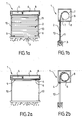
figures 1 a et 1 b sont respectivement des vues de face et de côté, selon une coupe verticale, d'un dispositif d'ouverture et de fermeture conforme selon un mode de réalisation, plus particulièrement d'un volet roulant, l'organe mobile manoeuvré en butée basse, - les
figures 2a et 2b sont respectivement des vues de face et de côté, selon une coupe verticale du volet roulant tel qu'illustré auxfigures 1a et 1b , l'organe mobile manoeuvré en butée haute, - la
figure 3 est un diagramme schématique illustrant un procédé de commande conforme à l'invention, et plus particulièrement le déclenchement d'un mode d'apprentissage automatique des fins de course conforme à l'invention selon un mode de réalisation, - la
figure 4 est un diagramme schématique d'un procédé de commande conforme à l'invention, et plus particulièrement d'un mode d'apprentissage des fins de course selon un second mode de réalisation conforme à l'invention, - la
figure 5 est un diagramme schématique d'un procédé de commande conforme à l'invention, et plus particulièrement du déclenchement d'un mode d'apprentissage à fins de course réglables conforme à l'invention selon un mode de réalisation, - les
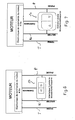
figures 6 et 7 sont respectivement deux exemples d'un moteur à gestion électronique de fins de course, à commande filaire, conforme à l'invention selon un mode de réalisation avec notamment un fil de commande, - les
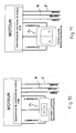
figures 8 et 9 sont respectivement deux exemples du câblage d'un moteur conforme à l'invention selon un mode de réalisation, avec notamment deux fils de commande, - les
figures 10 et 11 sont respectivement deux exemples du câblage d'un moteur conforme à l'invention, selon un troisième mode de réalisation, avec trois fils de commande, - les
figures 12 et 13 sont respectivement une vue schématique du câblage d'un moteur de l'état de la technique et son schéma électrique.
- the
figures 1 a and 1b are respectively front and side views, in a vertical section, of an opening and closing device according to an embodiment, more particularly of a roller shutter, the movable member operated in low stop, - the
Figures 2a and 2b are respectively front and side views, in a vertical section of the shutter as shown in FIGS.Figures 1a and 1b , the movable member maneuvered in high abutment, - the
figure 3 is a schematic diagram illustrating a control method according to the invention, and more particularly the triggering of an automatic learning mode of the limit switches according to the invention according to one embodiment, - the
figure 4 is a schematic diagram of a control method according to the invention, and more particularly of a learning mode of the limit switches according to a second embodiment according to the invention, - the
figure 5 is a schematic diagram of a control method according to the invention, and more particularly the triggering of a learning mode with adjustable travel according to the invention according to one embodiment, - the
Figures 6 and 7 are respectively two examples of an electronically controlled end-of-stroke motor, according to the invention according to one embodiment, in particular with a control wire, - the
Figures 8 and 9 are respectively two examples of the wiring of an engine according to the invention according to one embodiment, with in particular two control wires, - the
Figures 10 and 11 are respectively two examples of the wiring of an engine according to the invention, according to a third embodiment, with three control wires, - the
Figures 12 and 13 are respectively a schematic view of the wiring of a motor of the state of the art and its wiring diagram.
Nous décrivons par la suite le procédé de commande d'un dispositif d'ouverture et de fermeture conforme à l'invention.We next describe the control method of an opening and closing device according to the invention.
Dans la description, le dispositif d'ouverture et de fermeture se réfèrera selon les exemples illustrés à un volet roulant. Toutefois, l'invention n'est pas limitée à cette application particulière.In the description, the opening and closing device will refer, according to the examples illustrated, to a shutter. However, the invention is not limited to this particular application.
L'invention concerne un procédé de commande d'un dispositif 1 de fermeture et d'ouverture, tel qu'un volet roulant, comportant un organe mobile 2, tel qu'un tablier.The invention relates to a control method of a
L'organe mobile 2 se déplace entre deux positions extrêmes matérialisées par un ou des dispositifs de fins de course.The
Le dispositif d'ouverture et de fermeture 1 comprend des moyens d'actionnement de l'organe mobile constitué par un moteur électrique, notamment avec un réducteur, par exemple du type tubulaire et présente des moyens filaires de commande de l'organe mobile comportant au moins un interrupteur inverseur 20. Aussi, il s'agit d'une commande filaire, par exemple du type interrupteur mural. Le câblage au moteur est notamment à quatre fils (phase, neutre, commande, terre).The opening and
Le dispositif d'ouverture et de fermeture 1 présente des moyens pour détecter le déplacement de l'organe mobile constitués, par exemple, par un codeur angulaire, qui permet de suivre le déplacement du rotor du moteur. Le codeur angulaire peut être du type optique, comprenant notamment une roue codée par une alternance de segments réfléchissants ou non et associée à une cellule de détection optique, ou encore du type magnétique avec un capteur à effet hall associé à une roue codée magnétiquement par une alternance de pôles aimantés nord/sud.The opening and
Le dispositif comprend des moyens logiques de traitement constitués par un circuit électronique comprenant notamment un contrôleur, le procédé comportant, d'une part au moins un mode de programmation des fins de course, et d'autre part, un mode normal d'actionnement de l'organe mobile au cours duquel les moyens logiques de traitement provoquent l'arrêt de l'organe mobile lorsque les fins de course mémorisées sont approchées, voire atteintes par l'organe mobile.The device comprises logic processing means constituted by an electronic circuit including in particular a controller, the method comprising, on the one hand at least one programming mode of the limit switches, and on the other hand, a normal mode of actuation of the movable member during which the logic processing means cause the stopping of the movable member when the stored limit switches are approached or even reached by the movable member.
Plus particulièrement, les moyens pour détecter le déplacement de l'organe mobile, notamment le codeur angulaire, émettent des impulsions qui permettent au circuit électronique, notamment à un contrôleur, de connaître la position de l'organe mobile en incrémentant ou décrémentant un registre.More particularly, the means for detecting the displacement of the movable member, in particular the angular encoder, emit pulses which enable the electronic circuit, in particular a controller, to know the position of the mobile member by incrementing or decrementing a register.
Selon un exemple, lors de la programmation des fins de course, ce registre peut être notamment mis à zéro lors de la programmation de la première fin de course. Le tablier est ensuite actionné en direction de la deuxième butée physique, le registre s'incrémentant avec le déplacement de l'organe mobile jusqu'à la position de la deuxième position de fin de course. La valeur du registre est alors enregistrée dans une deuxième mémoire au registre.In one example, when programming the limit switches, this register can be set to zero when programming the first limit switch. The apron is then actuated towards the second physical stop, the register being incremented with the displacement of the movable member to the position of the second end position. The value of the register is then stored in a second memory in the register.
Lors du fonctionnement en mode normal de l'organe mobile, le premier registre, dénommé compteur de position en temps réel, suit le déplacement de l'organe mobile et s'incrémente ou se décrémente en fonction de ses déplacements, et peut être continuellement comparé à la valeur du deuxième registre.During operation in normal mode of the movable member, the first register, called real-time position counter, follows the displacement of the movable member and increments or decrements according to its movements, and can be continuously compared to the value of the second register.
Plus particulièrement, les moyens logiques de traitement coupent l'alimentation du moteur lorsque la fin de course basse est atteinte, ou encore à une fraction de tour avant la fin de la course basse, c'est-à-dire à quelques unités avant que le registre n'atteigne la valeur zéro, dans le cas de la descente du volet roulant. Dans le cas de la montée du volet roulant, lesdits moyens logiques de traitement coupent l'alimentation du moteur lorsque le compteur atteint la valeur de la fin de course haute, ou encore, à quelques unités de cette valeur, une fraction de tour avant que l'organe mobile n'atteigne la fin de course haute.More particularly, the logic processing means cut the power supply of the motor when the low end of stroke is reached, or a fraction of a turn before the end of the low stroke, that is to say a few units before the register reaches the value zero, in the case of the descent of the shutter. In the case of the rise of the shutter, said logic processing means cut off the power supply of the motor when the counter reaches the value of the high limit switch, or, a few units of this value, a fraction of a turn before the movable member reaches the upper limit of travel.
Selon l'invention, d'une part, le procédé consiste à alimenter de manière continue le circuit électronique des moyens logiques de traitement ainsi que lesdits moyens pour détecter la période de déplacement de l'organe mobile, lesdits moyens de déclenchement dudit au moins un mode de programmation des fins de course étant constitués par la carte électronique et plus particulièrement par des moyens de détection de changement d'état de l'interrupteur inverseur.According to the invention, on the one hand, the method consists in continuously feeding the electronic circuit of the logic processing means as well as said means for detecting the period of displacement of the movable member, said triggering means of said at least one programming mode of the limit switches being constituted by the electronic card and more particularly by means of detecting change of state of the inverter switch.
Selon le procédé de l'invention, d'autre part, on déclenche le ou chaque mode de programmation des fins de course désirées par des appuis fugitifs rapprochés sur l'interrupteur inverseur, du type impulsions, d'un nombre déterminé supérieur à un, et le cas échéant, distinct dans le cas d'une pluralité de modes de programmation.According to the method of the invention, on the other hand, the or each programming mode of the desired end positions is triggered by close fugitive supports on the reversing switch, of the pulse type, by a determined number greater than one, and where appropriate, distinct in the case of a plurality of programming modes.
Avantageusement, le procédé conforme à l'invention utilise l'interrupteur inverseur en place, quels que soient sa marque notamment et son mode de fonctionnement, pour transmettre un code qui sera compris et interprété par l'électronique de commande du dispositif. On remarque ainsi par ailleurs que la mise en oeuvre de cette technique nécessite l'alimentation continue de l'électronique de commande et donc du circuit électronique notamment pendant la salve d'appuis rapprochés.Advantageously, the method according to the invention uses the inverter switch in place, regardless of its particular brand and its mode of operation, to transmit a code that will be understood and interpreted by the control electronics of the device. It is also noted that the implementation of this technique requires feeding continuous control electronics and therefore the electronic circuit especially during the burst of close supports.
A cet effet, le câblage du dispositif d'ouverture et de fermeture doit, contrairement au câblage à commande filaire de l'état de l'art, illustré aux
Par exemple, quatre appuis fugitifs rapprochés peuvent permettre de déclencher le mode de programmation des fins de course. Un appui unique ou plusieurs appuis prolongés sur l'interrupteur provoquent quant à eux l'actionnement de l'organe mobile dans un sens ou dans l'autre. Le fonctionnement de ce procédé sera mieux compris à la lecture des exemples de fonctionnement.For example, four close fugitive supports can trigger the programming mode of the limit switches. A single support or several prolonged presses on the switch cause them to actuate the movable member in one direction or the other. The operation of this method will be better understood on reading the examples of operation.
Selon un mode de réalisation notamment, le dispositif peut comporter le cas échéant deux butées physiques 3, 4 pour l'organe mobile 2, le procédé comportant au moins deux modes de programmation des fins de course, avec d'une part, un mode d'apprentissage des fins de course automatiques au cours duquel les fins de course sont repérées par la détection et la reconnaissance automatique des positions des butées physiques, et d'autre part, un mode d'apprentissage des fins de course réglables au cours duquel les fins de course sont repérées et inscrites par des opérations de commande de l'utilisateur, le mode d'apprentissage des fins de course automatiques et le mode d'apprentissage des fins de course réglables étant respectivement déclenchés par un nombre N1 et un nombre N2 d'appuis fugitifs rapprochés avec N1 différent de N2.According to one particular embodiment, the device may comprise, where appropriate, two
Par exemple, pour N1 = 4, quatre impulsions font entrer le procédé dans le mode d'apprentissage des fins de course automatiques au cours duquel les positions des fins de course sont enregistrées dès la détection des butées physiques, puis à l'expiration d'une temporisation, ou encore dès que les deux fins de course sont enregistrées, le procédé passe en mode normal d'actionnement de l'organe mobile.For example, for N 1 = 4, four pulses bring the process into the learning mode of the automatic limit switches. during which the positions of the limit switches are recorded as soon as the physical stops are detected, then at the end of a time delay, or as soon as the two limit switches are recorded, the process switches to the normal operating mode of the mobile organ.
Par exemple pour, N2 = 6, six impulsions font entrer dans le mode de programmation des fins de course réglables. L'opérateur va donc commander l'organe mobile jusqu'à son point haut désiré par un seul ou plusieurs appuis sur la commande, puis la position de fin de course est enregistrée dans une mémoire du circuit électronique, notamment à l'expiration d'une première temporisation d'inaction du moteur. Ensuite, l'utilisateur descend jusqu'à son point bas désiré. La mémoire enregistre la position de cette deuxième fin de course, notamment à l'expiration d'une deuxième temporisation d'inaction du moteur. Une temporisation de sortie peut permettre ensuite le retour du procédé en mode normal d'actionnement.For example, for N 2 = 6, six pulses enter the programming mode of the adjustable limit switches. The operator will therefore control the movable member to its desired high point by one or more presses on the control, then the end position is stored in a memory of the electronic circuit, especially at the expiration of a first delay of inaction of the motor. Then the user goes down to his desired low point. The memory stores the position of this second limit switch, in particular when a second motor inaction timeout expires. An exit delay can then allow the return of the method in normal operation mode.
Il est à noter par ailleurs que l'alimentation en continu d'une part, des moyens logiques de traitement, particulièrement du circuit électronique et d'autre part, des moyens pour détecter la période de déplacement de l'organe mobile tel que notamment le codeur angulaire permet également de suivre sans discontinuité dans le temps la position réelle de l'organe mobile.It should also be noted that the continuous supply on the one hand, logic processing means, particularly the electronic circuit and, on the other hand, means for detecting the period of displacement of the movable member such as in particular the angular encoder also allows to follow without discontinuity in time the actual position of the movable member.
Dans le cas d'un glissement de l'organe mobile (moteur non actionné), les moteurs logiques de traitement via le codeur angulaire notamment peuvent continuer à prendre en compte l'information de déplacement. Lors du prochain actionnement de l'organe mobile, le circuit électronique provoque la coupure d'alimentation des bobinages du moteur aux fins de course, sans dérive.In the case of sliding of the movable member (motor not actuated), the logic processing engines via the angular encoder in particular can continue to take into account the displacement information. During the next actuation of the movable member, the electronic circuit causes the power cut of the motor windings for travel without drift.
En mode normal d'actionnement, selon un mode avantageux de réalisation, les moyens logiques de traitement peuvent provoquer l'arrêt de l'organe mobile, à savoir la coupure d'alimentation des bobinages du moteur dès la détection d'un obstacle, notamment intermédiaire. Toutefois, cette position n'est pas enregistrée comme fin de course.In normal operation mode, according to an advantageous embodiment, the logic processing means may cause the stop of the movable member, namely the power failure of the motor windings upon detection of an obstacle, in particular intermediate. However, this position is not recorded as a limit switch.
Selon ce mode de réalisation et dans le cas d'un apprentissage automatique des fins de course, la sensibilité de la détection au blocage en mode normal d'actionnement peut être différent de la sensibilité de détection en mode d'apprentissage des fins de course automatiques. Par exemple la sensibilité de la détection au blocage en mode normal d'actionnement peut être supérieure à la sensibilité de détection en mode d'apprentissage des fins de course automatiques, permettant à l'organe mobile de passer un point dur important dans la phase d'apprentissage alors qu'un point dur de même intensité provoquerait, selon cet exemple, l'arrêt de l'organe mobile dans le mode normal d'actionnement. Selon cet exemple, on part sur le postulat que des contraintes importantes sur le mécanisme peuvent être tolérées lors du mode d'apprentissage des fins de course automatiques, celles-ci ne l'étant plus lorsqu'à répétition, l'organe mobile subit ces contraintes lors du mode normal d'actionnement, le mécanisme du dispositif pouvant subir le phénomène de fatigue et finir par s'altérer.According to this embodiment and in the case of automatic learning of the limit switches, the sensitivity of the detection to the blocking in normal operation mode may be different from the detection sensitivity in the learning mode of the automatic limit switches. . For example, the sensitivity of the detection to the blocking in the normal operating mode may be greater than the detection sensitivity in learning mode of the automatic limit switches, allowing the mobile member to pass a significant hard point in the phase of activation. learning while a hard point of the same intensity would cause, according to this example, the stopping of the movable member in the normal mode of actuation. According to this example, it is postulated that important constraints on the mechanism can be tolerated in the learning mode of the automatic limit switches, these being no longer when the repetitive member, the mobile body undergoes these constraints in the normal mode of actuation, the mechanism of the device can undergo the phenomenon of fatigue and eventually deteriorate.
Nous décrivons maintenant en détails quelques exemples de modes d'apprentissage de fins de course plus particulièrement illustrés aux
Par exemple, à la
Plus particulièrement, tel qu'illustré à la
- départ d'une temporisation,
- actionnement de l'organe mobile dans un premier sens par l'opérateur,
- détection de la première butée physique, l'organe mobile étant arrêté par le circuit électronique (coupure, alimentation, bobinage, moteur), la position de la première fin de course est enregistrée, notamment par la mise à zéro d'un registre d'incrémentation/décrémentation,
- actionnement de l'organe mobile dans le deuxième sens par l'opérateur, le registre s'incrémentant selon les impulsions d'un codeur angulaire en fonction du déplacement de l'organe mobile,
- détection de la deuxième butée physique, le circuit électronique provoque l'arrêt du moteur (coupure alimentation bobinage moteur), et l'enregistrement de la deuxième fin de course, notamment en copiant la valeur du registre, dénommée compteur de position réelle dans un deuxième registre ou mémoire,
- à l'expiration de la temporisation, le circuit électronique provoque le retour en mode normal d'actionnement.
- start of a delay,
- actuation of the movable member in a first direction by the operator,
- detection of the first physical stop, the movable member being stopped by the electronic circuit (cutoff, power supply, winding, motor), the position of the first limit switch is recorded, in particular by setting to zero of a register of increment / decrement,
- actuation of the movable member in the second direction by the operator, the register being incremented according to the pulses of an angular encoder as a function of the displacement of the movable member,
- detection of the second physical stop, the electronic circuit causes the stop of the motor (power cut motor winding), and the recording of the second limit switch, in particular by copying the value of the register, called actual position counter in a second register or memory,
- when the timer expires, the electronic circuit causes the return to normal operation mode.
Dans le mode normal d'actionnement, la valeur du premier registre, à savoir le compteur de position est comparée sans cesse à la valeur de la deuxième mémoire. Lorsque le compteur de position réelle atteint une valeur de quelques unités supérieures à zéro, c'est-à-dire l'organe mobile est à une fraction de tour de la première fin de course, les moyens logiques de traitement provoquent l'arrêt du moteur (coupure, bobinage, moteur). Lorsque la valeur du compteur de position réelle est à quelques unités de la valeur de la deuxième mémoire, les moyens logiques de traitement provoquent l'arrêt du moteur (coupure alimentation bobinage moteur), notamment afin d'éviter que l'organe mobile ne bute trop fortement sur la butée physique haute.In the normal operating mode, the value of the first register, namely the position counter, is constantly compared to the value of the second memory. When the actual position counter reaches a value of a few units greater than zero, that is to say the movable member is at a fraction of a turn of the first limit switch, the logic means of processing cause the stopping of the motor (cutting, winding, motor). When the value of the actual position counter is a few units of the value of the second memory, the logic processing means causes the motor to stop (motor winding power failure), in particular in order to prevent the movable member from coming into play. too strongly on the high physical abutment.
Selon un autre exemple illustré à la
Plus particulièrement, selon ce mode de réalisation illustré à la
- actionnement dans un premier sens de l'organe mobile par une commande de l'opérateur,
- détection de la première butée physique; le circuit électronique provoque l'arrêt de l'organe mobile (coupure, alimentation, bobinage, moteur) et l'enregistrement de la première fin de course, la mémoire M1 est mise à un, la mémoire M2 restant à zéro. Un registre d'incrémentation/décrémentation est mis à zéro,
- actionnement dans un deuxième sens de l'organe mobile par l'opérateur, le registre s'incrémentant avec le déplacement de l'organe mobile,
- détection de la deuxième butée physique; le circuit électronique provoque l'arrêt du moteur (coupure alimentation bobinage moteur) et enregistre la deuxième position de fin de course, notamment en recopiant la valeur du compteur de position réelle dans une deuxième mémoire au registre. La mémoire M2 est mise à un,
- lorsque M1 = 1 et M2 = 2, le circuit électronique passe en mode normal d'actionnement de l'organe mobile.
- actuation in a first direction of the movable member by an operator command,
- detecting the first physical stop; the electronic circuit causes the stopping of the movable member (cut, power supply, winding, motor) and the recording of the first limit switch, the memory M 1 is set to one, the memory M 2 remaining at zero. An increment / decrement register is set to zero,
- actuation in a second direction of the movable member by the operator, the register being incremented with the displacement of the movable member,
- detecting the second physical stop; the electronic circuit causes the engine to stop (motor winding power failure) and records the second end position, in particular by copying the value of the actual position counter in a second memory to the register. The memory M 2 is set to one,
- when M 1 = 1 and M 2 = 2, the electronic circuit goes into normal operation mode of the movable member.
Comme le mode de réalisation précédent, le premier registre (compteur de position réelle) est comparé sans cesse à la valeur de la deuxième mémoire. Lorsque le compteur de position réelle est à quelques unités, soit de la valeur zéro (proche de la première fin de course), soit de la valeur de la deuxième mémoire (proche de la deuxième fin de course), le circuit électronique coupe l'alimentation des bobinages moteurs afin d'éviter des efforts trop importants lorsque l'organe mobile rencontre les butées physiques.Like the previous embodiment, the first register (actual position counter) is constantly compared to the value of the second memory. When the actual position counter is a few units, either of the zero value (close to the first limit switch) or the value of the second memory (close to the second limit switch), the electronic circuit interrupts the motor windings to avoid excessive forces when the movable member meets the physical stops.
Selon l'exemple de réalisation de la
Plus particulièrement tel qu'illustré à la
- actionnement dans un premier sens en appuyant sur l'interrupteur inverseur (par un ou plusieurs appuis) jusqu'à la position de fin de course désirée, par exemple, le point bas,
- à l'expiration d'une première temporisation d'inaction du moteur, le circuit électronique enregistre la position comme première fin de course, notamment en mettant à zéro un registre de position,
- actionnement dans un deuxième sens par l'utilisateur en appuyant sur l'interrupteur inverseur, par un ou plusieurs appuis jusqu'à la deuxième position de fin de course désirée, au cours de cet actionnement, le registre s'incrémente selon le déplacement de l'organe mobile,
- à l'expiration d'une deuxième temporisation d'inaction du moteur, le circuit électronique provoque l'enregistrement de la position haute comme deuxième fin de course, et copie la valeur du registre dans une deuxième mémoire ou registre,
- une temporisation de sortie permet alors le retour en mode normal d'actionnement.
- actuation in a first direction by pressing the reversing switch (by one or more supports) to the desired end position, for example, the low point,
- at the expiration of a first motor inaction delay, the electronic circuit registers the position as the first limit switch, in particular by zeroing a position register,
- actuated in a second direction by the user by pressing the reversing switch, by one or more supports to the second desired end position, during this actuation, the register is incremented according to the displacement of the mobile organ,
- at the expiration of a second motor inaction delay, the electronic circuit causes the high position to be recorded as the second limit switch, and copies the value of the register to a second memory or register,
- an exit delay then allows the return to normal operation mode.
Avantageusement, chaque enregistrement des fins de course peut être signalé par les moyens logiques de traitement, en actionnant l'organe mobile suivant un aller-retour. Par exemple, s'il s'agit de la fin de course haute, l'enregistrement est signalé par une rotation de descente du rotor puis une rotation de montée. S'il s'agit de la fin de course basse, l'enregistrement est signalé par une rotation de montée suivie d'une rotation de descente du rotor.Advantageously, each recording of the limit switches can be signaled by the logical processing means, by operating the movable member following a round trip. For example, if it is the high limit switch, the recording is signaled by a downward rotation of the rotor and a rise rotation. If it is the low end of the stroke, the recording is signaled by a rise rotation followed by a downward rotation of the rotor.
En mode normal d'actionnement, la valeur du premier registre (compteur de position réelle) s'incrémente et se décrémente en fonction des déplacements de l'organe mobile et est comparée sans cesse à la valeur de la deuxième mémoire.In normal operation mode, the value of the first register (actual position counter) is incremented and decremented according to the movements of the movable member and is constantly compared to the value of the second memory.
Lorsque le compteur est à zéro (fin de course basse), ou atteint la valeur de la deuxième mémoire (fin de course haute), l'électronique arrête le moteur.When the counter is at zero (low end limit), or reaches the value of the second memory (high limit switch), the electronics stops the motor.
Le dispositif d'ouverture et de fermeture 1 peut être un volet roulant, tel qu'illustré aux
En outre, le volet roulant comporte entre l'extrémité supérieure du tablier de volet roulant et le tambour d'enroulement 6, un verrou d'attache, interdisant, d'une part, le relevage frauduleux du tablier en positon basse, permettant d'autre part au moteur de se bloquer lorsque le tablier atteint sa butée basse 3, tel qu'illustré aux
Le procédé selon l'invention peut être mis en oeuvre par un dispositif de fermeture et d'ouverture. Ce dispositif comporte un organe mobile 2, des moyens d'actionnement de l'organe mobile constitués par un moteur électrique 5, des moyens filaires de commande de l'organe mobile comprenant au moins un interrupteur inverseur, des moyens pour détecter le déplacement de l'organe mobile, ainsi que des moyens logiques de traitement constitués par un circuit électronique pour l'actionnement de l'organe mobile et de la gestion des fins de course.The method according to the invention can be implemented by a closing and opening device. This device comprises a
Le dispositif comporte, d'une part, au moins un mode de programmation des fins de course, et d'autre part, au moins un mode d'actionnement de l'organe mobile au cours duquel les moyens logiques de traitement provoquent l'arrêt de l'organe mobile lorsque les fins de course sont approchées, voire atteintes, le dispositif présentant des moyens de déclenchement dudit au moins un mode de programmation des fins de course.The device comprises, on the one hand, at least one programming mode of the limit switches, and on the other hand, at least one mode of actuation of the movable member during which the logic means of treatment cause the stop of the movable member when the limit switches are approached, or even reached, the device having means for triggering said at least one programming mode of the limit switches.
Le câblage électrique du dispositif est tel qu'il assure une alimentation en continu du circuit électronique ainsi que des moyens pour détecter la période de déplacement de l'organe mobile, quel que soit l'état de l'interrupteur inverseur. Lesdits moyens de déclenchement dudit au moins un mode de programmation de fin de course sont constitués par l'interrupteur inverseur ainsi que par le circuit électronique et plus particulièrement des moyens de détection de changement d'état de l'interrupteur inverseur.The electrical wiring of the device is such that it provides a continuous supply of the electronic circuit and means for detecting the period of movement of the movable member, regardless of the state of the inverter switch. Said triggering means of said at least one end-of-stroke programming mode are constituted by the inverting switch as well as by the electronic circuit and more particularly state change detection means of the reversing switch.
Trois modes de réalisation d'un câblage conforme à l'invention sont respectivement illustrés aux
Le mode de réalisation des
L'électronique de commande, plus particulièrement le circuit électronique présente des moyens pour détecter la phase et le neutre. Lorsque la phase est détectée, le circuit électronique actionne un relais pour provoquer la rotation du moteur dans un sens. Lorsque le neutre est détecté, le circuit électronique actionne un autre relais pour provoquer la rotation du moteur dans l'autre sens.The control electronics, more particularly the electronic circuit has means for detecting the phase and the neutral. When the phase is detected, the electronic circuit operates a relay to cause rotation of the motor in one direction. When the neutral is detected, the electronic circuit actuates another relay to cause the rotation of the motor in the other direction.
On notera que cet exemple nécessite un câblage simple, comprenant trois fils au minimum dans le cas d'un système monophasé, le cas échéant quatre lorsque la terre est nécessaire. Un câblage à un seul fil de commande est également possible pour un système triphasé.Note that this example requires simple wiring, comprising at least three wires in the case of a single-phase system, if necessary four when the earth is necessary. Single-wire control wiring is also possible for a three-phase system.
Le mode de réalisation des
L'électronique de commande, notamment le circuit électronique présente des moyens pour détecter la phase (P) soit sur le premier fil de commande, soit sur le deuxième fil de commande. Si la phase est détectée sur le premier fil de commande, les moyens logiques de traitement actionnent un relais pour provoquer la rotation du moteur dans un sens. Si la phase est détectée sur le deuxième fil de commande, un autre relais est actionné et provoque la rotation du moteur dans l'autre sens. Si aucune phase n'est détectée, ni sur le premier fil, ni sur le deuxième fil de commande, le moteur reste à l'arrêt. Il est à noter qu'un câblage à deux fils peut être également utilisé pour un système triphasé.The control electronics, in particular the electronic circuit, have means for detecting the phase (P) either on the first control wire or on the second control wire. If the phase is detected on the first control wire, the logic processing means operates a relay to cause rotation of the motor in one direction. If the phase is detected on the second control wire, another relay is actuated and causes the rotation of the motor in the other direction. If no phase is detected, neither on the first wire nor on the second control wire, the motor remains at a standstill. It should be noted that two-wire wiring can also be used for a three-phase system.
Le mode de réalisation des
Enfin, le procédé selon l'invention peut être mis en oeuvre par un moteur à gestion des fins de cours électroniques à commande filaire.Finally, the method according to the invention can be implemented by a wire-controlled e-course management engine.
Ledit moteur comprend des moyens pour détecter le déplacement du rotor dudit moteur, ainsi qu'un circuit électronique pour l'enregistrement des fins de course et la gestion desdites fins de course lors de l'actionnement dudit moteur. Au moins une ligne de phase P et une ligne de neutre N sont prévues pour l'alimentation dudit moteur, ainsi que des moyens de commande du moteur dans un sens ou dans l'autre, constitués par un interrupteur inverseur.Said motor comprises means for detecting the displacement of the rotor of said motor, as well as an electronic circuit for recording the limit switches and the management of said limit switches during the actuation of said motor. At least one phase line P and one neutral line N are provided for supplying said motor, as well as means for controlling the motor in one direction or the other, constituted by an inverting switch.
Le moteur à gestion des fins de course électroniques comporte, d'une part, au moins un mode de programmation des fins de course, et d'autre part, un mode normal d'actionnement de l'organe mobile au cours duquel le circuit électronique provoque l'arrêt du rotor lorsque les fins de course sont approchées, voire atteintes. Le moteur présente des moyens de déclenchement dudit au moins un mode de programmation des fins de course.The engine with electronic limit switches comprises, on the one hand, at least one mode of programming of the limit switches, and on the other hand, a normal mode of actuation of the movable member during which the electronic circuit causes the rotor to stop when the limit switches are approached or even reached. The motor has means for triggering said at least one programming mode of the limit switches.
Selon l'invention, la ligne de phase P et la ligne de neutre N alimentent directement et en permanence ledit circuit électronique ainsi que lesdits moyens pour détecter le déplacement de l'organe mobile, quel que soit l'état de l'interrupteur inverseur. Les moyens de déclenchement dudit au moins un mode de programmation des fins de course sont constitués par l'interrupteur inverseur ainsi que par des moyens de détection de changement d'état de l'interrupteur inverseur.According to the invention, the phase line P and the neutral line N supply directly and permanently said electronic circuit as well as said means for detecting the displacement of the movable member, whatever the state of the inverter switch. The triggering means of said at least one programming mode of the limit switches are constituted by the inverter switch and by means of changeover state detection means of the inverter switch.
Ce moteur à gestion des fins de course électroniques permettra ainsi la mise en oeuvre du procédé conforme à l'invention.This engine with electronic limit switches will thus allow the implementation of the method according to the invention.
Il s'agit d'un moteur dit polyvalent. Avantageusement, le moteur peut présenter des moyens pour prendre en compte le déplacement du rotor quel que soit l'état de l'interrupteur inverseur 20. Aussi, un registre s'incrémente ou se décrémente dans le cas de la rotation du rotor, même si l'interrupteur est dans sa position d'arrêt.This is a so-called versatile engine. Advantageously, the motor may have means for taking into account the displacement of the rotor whatever the state of the inverting
Tel qu'illustré à la
Selon l'exemple de la
Si l'interrupteur est positionné vers le haut ou vers le bas, le circuit électronique détecte soit le neutre, soit la phase du secteur sur la ligne commandée et actionne le moteur dans un sens ou dans l'autre en fonction de la ligne détectée.If the switch is positioned up or down, the electronic circuit detects either the neutral or the sector phase on the commanded line and operates the motor in one direction or the other depending on the line detected.
Le principe de fonctionnement est similaire pour l'exemple de la
Naturellement, d'autres modes de réalisation auraient pu être envisagés sans pour autant sortir du cadre de l'invention définie par les revendications ci-après.Naturally, other embodiments could have been envisaged without departing from the scope of the invention defined by the claims below.
Claims (8)
Applications Claiming Priority (1)
| Application Number | Priority Date | Filing Date | Title |
|---|---|---|---|
| FR0801227A FR2928400B1 (en) | 2008-03-06 | 2008-03-06 | METHOD FOR CONTROLLING A DEVICE FOR CLOSING AND OPENING A WIRELESS OPENING OPENER |
Publications (2)
| Publication Number | Publication Date |
|---|---|
| EP2098677A1 true EP2098677A1 (en) | 2009-09-09 |
| EP2098677B1 EP2098677B1 (en) | 2011-09-28 |
Family
ID=39971003
Family Applications (1)
| Application Number | Title | Priority Date | Filing Date |
|---|---|---|---|
| EP09370004A Active EP2098677B1 (en) | 2008-03-06 | 2009-03-05 | Method of controlling a device for closing and opening a door with wired control |
Country Status (3)
| Country | Link |
|---|---|
| EP (1) | EP2098677B1 (en) |
| AT (1) | ATE526482T1 (en) |
| FR (1) | FR2928400B1 (en) |
Cited By (4)
| Publication number | Priority date | Publication date | Assignee | Title |
|---|---|---|---|---|
| FR2987158A1 (en) * | 2012-02-20 | 2013-08-23 | Somfy Sas | METHOD FOR OPERATING A CONTROL CABINET |
| EP2450523A3 (en) * | 2010-11-08 | 2014-08-20 | ARCA Beteiligungen GmbH | Drive for a darkening device |
| US20210063990A1 (en) * | 2019-08-26 | 2021-03-04 | Toyota Motor Engineering & Manufacturing North America, Inc. | Interface assemblies for manufacturing components |
| EP3783190A3 (en) * | 2019-08-16 | 2021-03-10 | Ningbo Sunfree Motor Technology Company Limited | Curtain remote controller and a method for setting remote control stroke thereof |
Citations (5)
| Publication number | Priority date | Publication date | Assignee | Title |
|---|---|---|---|---|
| EP0439422A1 (en) * | 1990-01-26 | 1991-07-31 | Somfy | Safety mechanism for motorised roller shutters |
| EP0744524A2 (en) * | 1995-05-24 | 1996-11-27 | Robert Bosch Gmbh | Device for the electronic control of the movements of a roller shutter |
| US6078159A (en) | 1999-02-17 | 2000-06-20 | The Chamberlain Group, Inc. | Method and apparatus for programming a logic board from switching power |
| EP1626154A1 (en) * | 2004-08-10 | 2006-02-15 | Somfy SAS | Method of operating a rollerblind, controlled and powered through a wire control interface |
| DE102004041293A1 (en) * | 2004-08-25 | 2006-03-09 | Provita Gmbh | Rolling shutter rising and lowering controlling device, has memory storing data of upper and lower switch-off positions for shutter, automatic test drive determining positions, and control device stopping drive motor on respective positions |
Family Cites Families (1)
| Publication number | Priority date | Publication date | Assignee | Title |
|---|---|---|---|---|
| FR2874291B1 (en) * | 2004-08-10 | 2006-11-17 | Somfy Sas | ELECTRIC ROLLING SHUTTER ACTUATOR HAVING A CONTROL INTERFACE PROVIDED WITH OPENING ELECTRICAL CONTACTS |
-
2008
- 2008-03-06 FR FR0801227A patent/FR2928400B1/en active Active
-
2009
- 2009-03-05 EP EP09370004A patent/EP2098677B1/en active Active
- 2009-03-05 AT AT09370004T patent/ATE526482T1/en not_active IP Right Cessation
Patent Citations (5)
| Publication number | Priority date | Publication date | Assignee | Title |
|---|---|---|---|---|
| EP0439422A1 (en) * | 1990-01-26 | 1991-07-31 | Somfy | Safety mechanism for motorised roller shutters |
| EP0744524A2 (en) * | 1995-05-24 | 1996-11-27 | Robert Bosch Gmbh | Device for the electronic control of the movements of a roller shutter |
| US6078159A (en) | 1999-02-17 | 2000-06-20 | The Chamberlain Group, Inc. | Method and apparatus for programming a logic board from switching power |
| EP1626154A1 (en) * | 2004-08-10 | 2006-02-15 | Somfy SAS | Method of operating a rollerblind, controlled and powered through a wire control interface |
| DE102004041293A1 (en) * | 2004-08-25 | 2006-03-09 | Provita Gmbh | Rolling shutter rising and lowering controlling device, has memory storing data of upper and lower switch-off positions for shutter, automatic test drive determining positions, and control device stopping drive motor on respective positions |
Cited By (6)
| Publication number | Priority date | Publication date | Assignee | Title |
|---|---|---|---|---|
| EP2450523A3 (en) * | 2010-11-08 | 2014-08-20 | ARCA Beteiligungen GmbH | Drive for a darkening device |
| FR2987158A1 (en) * | 2012-02-20 | 2013-08-23 | Somfy Sas | METHOD FOR OPERATING A CONTROL CABINET |
| EP2629274A3 (en) * | 2012-02-20 | 2014-05-21 | Somfy SAS | Operating method of a control cabinet |
| EP3783190A3 (en) * | 2019-08-16 | 2021-03-10 | Ningbo Sunfree Motor Technology Company Limited | Curtain remote controller and a method for setting remote control stroke thereof |
| US20210063990A1 (en) * | 2019-08-26 | 2021-03-04 | Toyota Motor Engineering & Manufacturing North America, Inc. | Interface assemblies for manufacturing components |
| US11650562B2 (en) * | 2019-08-26 | 2023-05-16 | Toyota Motor Engineering & Manufacturing North America, Inc. | Interface assemblies for manufacturing components |
Also Published As
| Publication number | Publication date |
|---|---|
| FR2928400B1 (en) | 2011-10-28 |
| ATE526482T1 (en) | 2011-10-15 |
| EP2098677B1 (en) | 2011-09-28 |
| FR2928400A1 (en) | 2009-09-11 |
Similar Documents
| Publication | Publication Date | Title |
|---|---|---|
| EP1510649B1 (en) | Method of initialising a roller blind | |
| EP0426577B1 (en) | Method and device for moving a shade element to adjustable stable positions and installation applying such | |
| EP2098677B1 (en) | Method of controlling a device for closing and opening a door with wired control | |
| FR2680437A1 (en) | MOUNTING FOR MONITORING CLOSING ELEMENTS DRIVEN BY AN ELECTRIC MOTOR. | |
| FR2573551A1 (en) | CONTROL DEVICE FOR ROLLING SHUTTER OR THE LIKE WITH ADJUSTABLE BLADES | |
| FR2925932A1 (en) | METHOD FOR ADJUSTING A MOTORIZED SOLAR PROTECTION SYSTEM NOT COMPRISING A FRONT STOP. | |
| JP2004038945A (en) | Process for learning travel limit of roller blind actuator | |
| EP1446548B1 (en) | Method for matching the command issued of the direction of an electric motor in a closure installation or the like such as a roller shutter | |
| FR2740552A1 (en) | METHOD FOR CONTROLLING THE MOVEMENT PATH OF A WORKPIECE | |
| EP3177797B1 (en) | Method for controlling the operation of a motorized drive device for a home automation installation and motorized drive device operating using this method | |
| FR2928401A1 (en) | Opening and closing device i.e. motorized roller blind, controlling method, involves continuously feeding electronic circuit and detection unit, and passing mobile body to travel limit learning mode during detection of powering of circuit | |
| EP3121364B1 (en) | Method for controlling a screen roller actuator and system implementing said method | |
| EP2808479B1 (en) | Method and device for actuating a mobile closure, concealment, solar protection or screen element | |
| EP2099126B1 (en) | Motor with electronic end-of-travel management | |
| EP1160415B1 (en) | Control device for motor driven darkening systems with program selection | |
| FR2755998A1 (en) | DEVICE FOR AUTOMATICALLY STOPPING A MOTOR DRIVING A TUBE FOR ROLLING A SHUTTER | |
| EP1541798B1 (en) | Learning method for a motorised screen and a device for performing said method | |
| EP2098935A2 (en) | Motor with electronic end-of-travel management and method for installing an opening and closing device such as, in particular, a roller blind comprising such a motor | |
| EP3470616B1 (en) | Automated method for regulating a roller shutter installation provided with a locking mechanism | |
| EP3205810A1 (en) | Apparatus for remote control of devices for closing a rack such as a leaf or roller shutter | |
| EP1154121B1 (en) | Perfectioned control for motor driven shading devices | |
| EP3597848B1 (en) | Method of managing obstacles in an installation by controlling the movements of door leafs or hinged shutters | |
| EP3514307A1 (en) | Management of the combined movement of two motorised leaves in the event of one of the leaves encountering an obstacle | |
| EP1122404B1 (en) | Movement control for a closing device which rolls on a motor driven roller, and device for implementing such a control | |
| EP3470617B1 (en) | Method for automated control of a roller shutter installation and roller shutter installation |
Legal Events
| Date | Code | Title | Description |
|---|---|---|---|
| PUAI | Public reference made under article 153(3) epc to a published international application that has entered the european phase |
Free format text: ORIGINAL CODE: 0009012 |
|
| AK | Designated contracting states |
Kind code of ref document: A1 Designated state(s): AT BE BG CH CY CZ DE DK EE ES FI FR GB GR HR HU IE IS IT LI LT LU LV MC MK MT NL NO PL PT RO SE SI SK TR |
|
| AX | Request for extension of the european patent |
Extension state: AL BA RS |
|
| 17P | Request for examination filed |
Effective date: 20100305 |
|
| 17Q | First examination report despatched |
Effective date: 20100330 |
|
| AKX | Designation fees paid |
Designated state(s): AT BE BG CH CY CZ DE DK EE ES FI FR GB GR HR HU IE IS IT LI LT LU LV MC MK MT NL NO PL PT RO SE SI SK TR |
|
| GRAP | Despatch of communication of intention to grant a patent |
Free format text: ORIGINAL CODE: EPIDOSNIGR1 |
|
| GRAS | Grant fee paid |
Free format text: ORIGINAL CODE: EPIDOSNIGR3 |
|
| GRAA | (expected) grant |
Free format text: ORIGINAL CODE: 0009210 |
|
| AK | Designated contracting states |
Kind code of ref document: B1 Designated state(s): AT BE BG CH CY CZ DE DK EE ES FI FR GB GR HR HU IE IS IT LI LT LU LV MC MK MT NL NO PL PT RO SE SI SK TR |
|
| REG | Reference to a national code |
Ref country code: GB Ref legal event code: FG4D Free format text: NOT ENGLISH |
|
| REG | Reference to a national code |
Ref country code: CH Ref legal event code: EP |
|
| REG | Reference to a national code |
Ref country code: IE Ref legal event code: FG4D |
|
| REG | Reference to a national code |
Ref country code: DE Ref legal event code: R096 Ref document number: 602009002832 Country of ref document: DE Effective date: 20111124 |
|
| RAP2 | Party data changed (patent owner data changed or rights of a patent transferred) |
Owner name: DEPRAT JEAN SA |
|
| REG | Reference to a national code |
Ref country code: NL Ref legal event code: VDEP Effective date: 20110928 |
|
| PG25 | Lapsed in a contracting state [announced via postgrant information from national office to epo] |
Ref country code: LT Free format text: LAPSE BECAUSE OF FAILURE TO SUBMIT A TRANSLATION OF THE DESCRIPTION OR TO PAY THE FEE WITHIN THE PRESCRIBED TIME-LIMIT Effective date: 20110928 Ref country code: HR Free format text: LAPSE BECAUSE OF FAILURE TO SUBMIT A TRANSLATION OF THE DESCRIPTION OR TO PAY THE FEE WITHIN THE PRESCRIBED TIME-LIMIT Effective date: 20110928 Ref country code: NO Free format text: LAPSE BECAUSE OF FAILURE TO SUBMIT A TRANSLATION OF THE DESCRIPTION OR TO PAY THE FEE WITHIN THE PRESCRIBED TIME-LIMIT Effective date: 20111228 Ref country code: FI Free format text: LAPSE BECAUSE OF FAILURE TO SUBMIT A TRANSLATION OF THE DESCRIPTION OR TO PAY THE FEE WITHIN THE PRESCRIBED TIME-LIMIT Effective date: 20110928 Ref country code: SE Free format text: LAPSE BECAUSE OF FAILURE TO SUBMIT A TRANSLATION OF THE DESCRIPTION OR TO PAY THE FEE WITHIN THE PRESCRIBED TIME-LIMIT Effective date: 20110928 |
|
| LTIE | Lt: invalidation of european patent or patent extension |
Effective date: 20110928 |
|
| PG25 | Lapsed in a contracting state [announced via postgrant information from national office to epo] |
Ref country code: AT Free format text: LAPSE BECAUSE OF FAILURE TO SUBMIT A TRANSLATION OF THE DESCRIPTION OR TO PAY THE FEE WITHIN THE PRESCRIBED TIME-LIMIT Effective date: 20110928 Ref country code: GR Free format text: LAPSE BECAUSE OF FAILURE TO SUBMIT A TRANSLATION OF THE DESCRIPTION OR TO PAY THE FEE WITHIN THE PRESCRIBED TIME-LIMIT Effective date: 20111229 Ref country code: LV Free format text: LAPSE BECAUSE OF FAILURE TO SUBMIT A TRANSLATION OF THE DESCRIPTION OR TO PAY THE FEE WITHIN THE PRESCRIBED TIME-LIMIT Effective date: 20110928 Ref country code: SI Free format text: LAPSE BECAUSE OF FAILURE TO SUBMIT A TRANSLATION OF THE DESCRIPTION OR TO PAY THE FEE WITHIN THE PRESCRIBED TIME-LIMIT Effective date: 20110928 Ref country code: CY Free format text: LAPSE BECAUSE OF FAILURE TO SUBMIT A TRANSLATION OF THE DESCRIPTION OR TO PAY THE FEE WITHIN THE PRESCRIBED TIME-LIMIT Effective date: 20110928 |
|
| REG | Reference to a national code |
Ref country code: AT Ref legal event code: MK05 Ref document number: 526482 Country of ref document: AT Kind code of ref document: T Effective date: 20110928 |
|
| REG | Reference to a national code |
Ref country code: IE Ref legal event code: FD4D |
|
| PG25 | Lapsed in a contracting state [announced via postgrant information from national office to epo] |
Ref country code: SK Free format text: LAPSE BECAUSE OF FAILURE TO SUBMIT A TRANSLATION OF THE DESCRIPTION OR TO PAY THE FEE WITHIN THE PRESCRIBED TIME-LIMIT Effective date: 20110928 Ref country code: IS Free format text: LAPSE BECAUSE OF FAILURE TO SUBMIT A TRANSLATION OF THE DESCRIPTION OR TO PAY THE FEE WITHIN THE PRESCRIBED TIME-LIMIT Effective date: 20120128 Ref country code: CZ Free format text: LAPSE BECAUSE OF FAILURE TO SUBMIT A TRANSLATION OF THE DESCRIPTION OR TO PAY THE FEE WITHIN THE PRESCRIBED TIME-LIMIT Effective date: 20110928 |
|
| PG25 | Lapsed in a contracting state [announced via postgrant information from national office to epo] |
Ref country code: NL Free format text: LAPSE BECAUSE OF FAILURE TO SUBMIT A TRANSLATION OF THE DESCRIPTION OR TO PAY THE FEE WITHIN THE PRESCRIBED TIME-LIMIT Effective date: 20110928 Ref country code: RO Free format text: LAPSE BECAUSE OF FAILURE TO SUBMIT A TRANSLATION OF THE DESCRIPTION OR TO PAY THE FEE WITHIN THE PRESCRIBED TIME-LIMIT Effective date: 20110928 Ref country code: PT Free format text: LAPSE BECAUSE OF FAILURE TO SUBMIT A TRANSLATION OF THE DESCRIPTION OR TO PAY THE FEE WITHIN THE PRESCRIBED TIME-LIMIT Effective date: 20120130 Ref country code: EE Free format text: LAPSE BECAUSE OF FAILURE TO SUBMIT A TRANSLATION OF THE DESCRIPTION OR TO PAY THE FEE WITHIN THE PRESCRIBED TIME-LIMIT Effective date: 20110928 |
|
| PG25 | Lapsed in a contracting state [announced via postgrant information from national office to epo] |
Ref country code: IE Free format text: LAPSE BECAUSE OF FAILURE TO SUBMIT A TRANSLATION OF THE DESCRIPTION OR TO PAY THE FEE WITHIN THE PRESCRIBED TIME-LIMIT Effective date: 20110928 Ref country code: DK Free format text: LAPSE BECAUSE OF FAILURE TO SUBMIT A TRANSLATION OF THE DESCRIPTION OR TO PAY THE FEE WITHIN THE PRESCRIBED TIME-LIMIT Effective date: 20110928 |
|
| PLBE | No opposition filed within time limit |
Free format text: ORIGINAL CODE: 0009261 |
|
| STAA | Information on the status of an ep patent application or granted ep patent |
Free format text: STATUS: NO OPPOSITION FILED WITHIN TIME LIMIT |
|
| PG25 | Lapsed in a contracting state [announced via postgrant information from national office to epo] |
Ref country code: PL Free format text: LAPSE BECAUSE OF FAILURE TO SUBMIT A TRANSLATION OF THE DESCRIPTION OR TO PAY THE FEE WITHIN THE PRESCRIBED TIME-LIMIT Effective date: 20110928 |
|
| 26N | No opposition filed |
Effective date: 20120629 |
|
| REG | Reference to a national code |
Ref country code: DE Ref legal event code: R097 Ref document number: 602009002832 Country of ref document: DE Effective date: 20120629 |
|
| PG25 | Lapsed in a contracting state [announced via postgrant information from national office to epo] |
Ref country code: MC Free format text: LAPSE BECAUSE OF NON-PAYMENT OF DUE FEES Effective date: 20120331 |
|
| PG25 | Lapsed in a contracting state [announced via postgrant information from national office to epo] |
Ref country code: MK Free format text: LAPSE BECAUSE OF FAILURE TO SUBMIT A TRANSLATION OF THE DESCRIPTION OR TO PAY THE FEE WITHIN THE PRESCRIBED TIME-LIMIT Effective date: 20110928 |
|
| PG25 | Lapsed in a contracting state [announced via postgrant information from national office to epo] |
Ref country code: ES Free format text: LAPSE BECAUSE OF FAILURE TO SUBMIT A TRANSLATION OF THE DESCRIPTION OR TO PAY THE FEE WITHIN THE PRESCRIBED TIME-LIMIT Effective date: 20120108 |
|
| PG25 | Lapsed in a contracting state [announced via postgrant information from national office to epo] |
Ref country code: BG Free format text: LAPSE BECAUSE OF FAILURE TO SUBMIT A TRANSLATION OF THE DESCRIPTION OR TO PAY THE FEE WITHIN THE PRESCRIBED TIME-LIMIT Effective date: 20111228 |
|
| PG25 | Lapsed in a contracting state [announced via postgrant information from national office to epo] |
Ref country code: MT Free format text: LAPSE BECAUSE OF FAILURE TO SUBMIT A TRANSLATION OF THE DESCRIPTION OR TO PAY THE FEE WITHIN THE PRESCRIBED TIME-LIMIT Effective date: 20110928 |
|
| REG | Reference to a national code |
Ref country code: CH Ref legal event code: PL |
|
| GBPC | Gb: european patent ceased through non-payment of renewal fee |
Effective date: 20130305 |
|
| PG25 | Lapsed in a contracting state [announced via postgrant information from national office to epo] |
Ref country code: GB Free format text: LAPSE BECAUSE OF NON-PAYMENT OF DUE FEES Effective date: 20130305 Ref country code: CH Free format text: LAPSE BECAUSE OF NON-PAYMENT OF DUE FEES Effective date: 20130331 Ref country code: LI Free format text: LAPSE BECAUSE OF NON-PAYMENT OF DUE FEES Effective date: 20130331 |
|
| PG25 | Lapsed in a contracting state [announced via postgrant information from national office to epo] |
Ref country code: TR Free format text: LAPSE BECAUSE OF FAILURE TO SUBMIT A TRANSLATION OF THE DESCRIPTION OR TO PAY THE FEE WITHIN THE PRESCRIBED TIME-LIMIT Effective date: 20110928 |
|
| PG25 | Lapsed in a contracting state [announced via postgrant information from national office to epo] |
Ref country code: LU Free format text: LAPSE BECAUSE OF NON-PAYMENT OF DUE FEES Effective date: 20120305 |
|
| PG25 | Lapsed in a contracting state [announced via postgrant information from national office to epo] |
Ref country code: HU Free format text: LAPSE BECAUSE OF FAILURE TO SUBMIT A TRANSLATION OF THE DESCRIPTION OR TO PAY THE FEE WITHIN THE PRESCRIBED TIME-LIMIT Effective date: 20090305 |
|
| REG | Reference to a national code |
Ref country code: FR Ref legal event code: PLFP Year of fee payment: 8 |
|
| PGFP | Annual fee paid to national office [announced via postgrant information from national office to epo] |
Ref country code: DE Payment date: 20160316 Year of fee payment: 8 |
|
| PGFP | Annual fee paid to national office [announced via postgrant information from national office to epo] |
Ref country code: IT Payment date: 20160318 Year of fee payment: 8 Ref country code: BE Payment date: 20160330 Year of fee payment: 8 |
|
| REG | Reference to a national code |
Ref country code: FR Ref legal event code: PLFP Year of fee payment: 9 |
|
| REG | Reference to a national code |
Ref country code: DE Ref legal event code: R119 Ref document number: 602009002832 Country of ref document: DE |
|
| PG25 | Lapsed in a contracting state [announced via postgrant information from national office to epo] |
Ref country code: DE Free format text: LAPSE BECAUSE OF NON-PAYMENT OF DUE FEES Effective date: 20171003 |
|
| PG25 | Lapsed in a contracting state [announced via postgrant information from national office to epo] |
Ref country code: IT Free format text: LAPSE BECAUSE OF NON-PAYMENT OF DUE FEES Effective date: 20170305 |
|
| REG | Reference to a national code |
Ref country code: BE Ref legal event code: MM Effective date: 20170331 |
|
| REG | Reference to a national code |
Ref country code: FR Ref legal event code: PLFP Year of fee payment: 10 |
|
| PG25 | Lapsed in a contracting state [announced via postgrant information from national office to epo] |
Ref country code: BE Free format text: LAPSE BECAUSE OF NON-PAYMENT OF DUE FEES Effective date: 20170331 |
|
| PGFP | Annual fee paid to national office [announced via postgrant information from national office to epo] |
Ref country code: FR Payment date: 20230118 Year of fee payment: 15 |