EP2096364A1 - Module of a terminal of an air-conditioning system for premises - Google Patents
Module of a terminal of an air-conditioning system for premises Download PDFInfo
- Publication number
- EP2096364A1 EP2096364A1 EP08425124A EP08425124A EP2096364A1 EP 2096364 A1 EP2096364 A1 EP 2096364A1 EP 08425124 A EP08425124 A EP 08425124A EP 08425124 A EP08425124 A EP 08425124A EP 2096364 A1 EP2096364 A1 EP 2096364A1
- Authority
- EP
- European Patent Office
- Prior art keywords
- deflector element
- module
- aperture
- head
- air
- Prior art date
- Legal status (The legal status is an assumption and is not a legal conclusion. Google has not performed a legal analysis and makes no representation as to the accuracy of the status listed.)
- Withdrawn
Links
Images


Classifications
-
- F—MECHANICAL ENGINEERING; LIGHTING; HEATING; WEAPONS; BLASTING
- F24—HEATING; RANGES; VENTILATING
- F24F—AIR-CONDITIONING; AIR-HUMIDIFICATION; VENTILATION; USE OF AIR CURRENTS FOR SCREENING
- F24F1/00—Room units for air-conditioning, e.g. separate or self-contained units or units receiving primary air from a central station
- F24F1/0007—Indoor units, e.g. fan coil units
- F24F1/0011—Indoor units, e.g. fan coil units characterised by air outlets
-
- F—MECHANICAL ENGINEERING; LIGHTING; HEATING; WEAPONS; BLASTING
- F24—HEATING; RANGES; VENTILATING
- F24F—AIR-CONDITIONING; AIR-HUMIDIFICATION; VENTILATION; USE OF AIR CURRENTS FOR SCREENING
- F24F11/00—Control or safety arrangements
- F24F11/70—Control systems characterised by their outputs; Constructional details thereof
- F24F11/72—Control systems characterised by their outputs; Constructional details thereof for controlling the supply of treated air, e.g. its pressure
- F24F11/79—Control systems characterised by their outputs; Constructional details thereof for controlling the supply of treated air, e.g. its pressure for controlling the direction of the supplied air
-
- F—MECHANICAL ENGINEERING; LIGHTING; HEATING; WEAPONS; BLASTING
- F24—HEATING; RANGES; VENTILATING
- F24F—AIR-CONDITIONING; AIR-HUMIDIFICATION; VENTILATION; USE OF AIR CURRENTS FOR SCREENING
- F24F11/00—Control or safety arrangements
- F24F11/30—Control or safety arrangements for purposes related to the operation of the system, e.g. for safety or monitoring
-
- F—MECHANICAL ENGINEERING; LIGHTING; HEATING; WEAPONS; BLASTING
- F24—HEATING; RANGES; VENTILATING
- F24F—AIR-CONDITIONING; AIR-HUMIDIFICATION; VENTILATION; USE OF AIR CURRENTS FOR SCREENING
- F24F13/00—Details common to, or for air-conditioning, air-humidification, ventilation or use of air currents for screening
- F24F13/08—Air-flow control members, e.g. louvres, grilles, flaps or guide plates
- F24F13/10—Air-flow control members, e.g. louvres, grilles, flaps or guide plates movable, e.g. dampers
- F24F13/14—Air-flow control members, e.g. louvres, grilles, flaps or guide plates movable, e.g. dampers built up of tilting members, e.g. louvre
- F24F13/1426—Air-flow control members, e.g. louvres, grilles, flaps or guide plates movable, e.g. dampers built up of tilting members, e.g. louvre characterised by actuating means
- F24F2013/1433—Air-flow control members, e.g. louvres, grilles, flaps or guide plates movable, e.g. dampers built up of tilting members, e.g. louvre characterised by actuating means with electric motors
-
- F—MECHANICAL ENGINEERING; LIGHTING; HEATING; WEAPONS; BLASTING
- F24—HEATING; RANGES; VENTILATING
- F24F—AIR-CONDITIONING; AIR-HUMIDIFICATION; VENTILATION; USE OF AIR CURRENTS FOR SCREENING
- F24F2110/00—Control inputs relating to air properties
Definitions
- the present invention relates to a module of a terminal of an air-conditioning system for premises according to the preamble of Claim 1.
- Said modules are known in the technology of this field and are commonly used for defining with maximum accuracy the space in which the terminal is to be received.
- the module comprises a structure insertable into a space provided in a wall and having a seating suitable for receiving a terminal of an air-conditioning system, for example a radiant element or a heat exchanger.
- an air-conditioning system for example a radiant element or a heat exchanger.
- the structure insertable into the space is equipped with a closure panel removably fixable to the structure and intended to close the seating partially.
- the module is equipped with an air entry aperture, an air outlet aperture and an orientable deflector element which intercepts the flow of air emerging from the outlet aperture.
- the deflector element is moreover orientable in a plurality of angular positions between an open position and a closed position.
- the module is equipped with an electric motor for actuating the orientable deflector element and with an electrical power source for supplying the electric motor.
- the orientable deflector element, the electric motor and the electrical power source are supported by the closure panel.
- the module described above has a series of drawbacks. For example, in the event that maintenance operations need to be carried out on the components of the module, it is necessary to disassemble the module itself by removing the closure panel, with consequent waste of time, and operating difficulties.
- such a module does not allow any possible replacements of components in a simple and rapid manner, with consequent increases in costs.
- this aim is achieved by a module having the characteristics of Claim 1.
- the reference 100 indicates as a whole a module of a terminal (not shown) of an air-conditioning system for premises, for example a radiant element or plate or a heat exchanger.
- the module 100 comprises a body 110 insertable in a space in a wall, a seating 111 and a closure panel 112.
- the space is formed in the wall more or less roughly by a building worker by removing a portion of material from the wall or by constructing the wall around it.
- the insertable body 110 has the shape of a box or formwork and may be made of sheet metal or plastics material or of wood and is suitable for receiving the terminal of an air-conditioning system within it.
- the module 100 has a first aperture 120 for the air entry and a second aperture 121 for the air outlet.
- the module 100 of the present invention it is possible to provide at least one head 1 equipped with a structure 10 removably associated with the module 100.
- the seating 111 of the module 100 is suitable for receiving one or more heads 1 in positive connection. In this way it is possible to permit the complete replacement of the head 1 according to requirements, in order to simplify, speed up and optimise the installation operations and/or any maintenance operations on the module 100.
- the structure 10 comprises two side walls 14 and 15, a rear wall 12 and a top wall, 13.
- the structure 10 has a first aperture 20 for the air entry, a second aperture 21 for the air outlet and a deflector element 11 for intercepting the flow of air emerging from the second aperture 21.
- the deflector element 11 extends in a predominant longitudinal direction X-X between the two side walls 14 and 15.
- the second aperture 21 for the air outlet is positioned at the front of the head 1.
- the second aperture 121 of the module 100 for the air outlet is associated with the first aperture 20 of the head 1 for the air entry in such a way as to obtain a circulation of air entering by the first aperture 120 of the module 100 and emerging directly from the second aperture 21 of the head 1.
- the head 1 comprises a guide means 50 associated with the structure 10 for supporting and guiding the displacement of the deflector element 11 between an open position and a closed position in which the deflector element 11 substantially closes the second aperture 21.
- a drive means 30 which, by means of a kinematic transmission means 70, is capable of actuating the deflector element 11 between the open position and the closed position with respect to the structure 10.
- the drive means 30 is associated with the deflector element 11.
- the deflector element 11 comprises a front side 11a facing towards the outside of the head 1 when the deflector element 11 is in the closed position, and an opposed rear side 11b.
- the drive means 30 is associated with the rear side 11b of the deflector element 11 and is equipped with a rotation shaft 31.
- the kinematic transmission means 70 comprises an assembly consisting of a pinion 32 and a rack 53.
- the pinion 32 is connected in a rotationally secure manner to the rotation shaft 31 of the drive means 30, and the rack 53 is integral with the structure 10.
- the drive means 30 transmits the motion to the pinion 32 this latter, since it is associated with the rack 53, allows the deflector element 11 to position itself in a plurality of positions between the open position, in which the deflector element 11 allows the air flow to emerge from the second aperture 21, and the closed position, in which the deflector element 11 interrupts the air flow emerging from the first aperture 20.
- the deflector element 11 can be positioned in a plurality of extremely precise positions, absolutely reliable and comfortable air-conditioning is ensured in the premises without the need for manual intervention for adjustment of the air-conditioning by a user.
- the guide means 50 is associated with the side wall 14 or 15.
- the guide means 50 comprises a slot 51 in the inner surface 52 of which is associated the rack 53 suitable for engaging with the pinion 32 for the actuation of the deflector element 11.
- the rack 53 may be associated with both the side walls 14 and 15, such that the head 1 can be equipped with a plurality of drive means 30 for obtaining even finer positioning of the deflector element 11.
- the module 100 comprises a connecting means 80 suitable for connecting the drive means 30 to the mains network for the power supply.
- the head 1 comprises a supply means 40 for supplying the drive means 30, such as, for example, typical batteries.
- the supply means 40 is mounted on board the head 1.
- the supply means 40 is mounted on board the deflector element 11.
- the deflector element 11 is equipped with an engagement means 60 coupled to the guide means 50.
- the engagement means 60 is equipped with sliding means 61 suitable for advancing in the guide means 60 during the movement of the deflector element 11 into the plurality of positions from the open position to the closed position and/or vice versa.
- the deflector element 11 may comprise at a first of its lateral ends a kinematic transmission means 70, and at a second of its ends, opposed to the first end, an engagement means 60 such as to ensure that the deflector element 11 has effective stability during the movement.
- the module 100 is equipped with an acquisition means 200 for acquiring the temperature of the premises and suitable for transforming the measured temperature value t0 into an electrical signal e(t0) proportional to the measured temperature value t0.
- a control means 210 is provided which is suitable for comparing the measured temperature value t0 with a predetermined temperature value t1.
- the predetermined temperature value t1 is the value desired by the user and set for example on a common thermostat.
- the module 100 moreover comprises a regulating means 220 in signal communication with the control means 210.
- the regulating means 220 is thus capable of sending a regulating signal to the drive means 30 for defining the orientation of the deflector element 11 on the basis of the comparison between the measured temperature value t0 and the predetermined temperature value t1.
- the regulating means 220 is suitable for obtaining the predetermined and desired temperature value t1 in the premises.
- the acquisition means 200, the control means 210 and the regulating means 220 all to be housed in the head 1.
- interventions by the specialised personnel may thus be even easier. It may even be possible, in the event of "off site” repairs, to completely replace the head 1 which is to be repaired with another, issued by the maintenance body, in order thus to avoid interruptions in operation for the entire period during which the user's head will be undergoing repair.
Landscapes
- Engineering & Computer Science (AREA)
- Chemical & Material Sciences (AREA)
- Combustion & Propulsion (AREA)
- Mechanical Engineering (AREA)
- General Engineering & Computer Science (AREA)
- Air-Flow Control Members (AREA)
Abstract
The invention concerns a module (100) of a terminal (2) of an air-conditioning system for premises, equipped with a head (1) having a structure (10) removably associated with the module (100). The structure (10) comprises two side walls (14, 15), a rear wall (12) and a top wall (13), a first aperture (20) for the air entry, a second aperture (21) for the air outlet, and a deflector element (11) for intercepting the flow of air emerging from the second aperture (21). The deflector element (11) extends in a predominant longitudinal direction (X-X) between the two side walls (14, 15). In addition, the structure (10) comprises a guide means (50) for supporting and guiding the displacement of the deflector element (11) between an open position and a closed position in which the deflector element (11) substantially closes the second aperture (21), and a drive means (30) operationally associated with the head (1) by means of a kinematic transmission means (70) for actuating the deflector element (11) between the open position and the closed position with respect to the structure (10).
Description
- The present invention relates to a module of a terminal of an air-conditioning system for premises according to the preamble of
Claim 1. - Said modules are known in the technology of this field and are commonly used for defining with maximum accuracy the space in which the terminal is to be received.
- An example of a module is described in Italian Patent application
MI2005A002363 - According to the prior art mentioned above, the module comprises a structure insertable into a space provided in a wall and having a seating suitable for receiving a terminal of an air-conditioning system, for example a radiant element or a heat exchanger.
- The structure insertable into the space is equipped with a closure panel removably fixable to the structure and intended to close the seating partially.
- In order to ensure correct circulation of the air, the module is equipped with an air entry aperture, an air outlet aperture and an orientable deflector element which intercepts the flow of air emerging from the outlet aperture. The deflector element is moreover orientable in a plurality of angular positions between an open position and a closed position.
- The module is equipped with an electric motor for actuating the orientable deflector element and with an electrical power source for supplying the electric motor. The orientable deflector element, the electric motor and the electrical power source are supported by the closure panel.
- The module described above, however, has a series of drawbacks. For example, in the event that maintenance operations need to be carried out on the components of the module, it is necessary to disassemble the module itself by removing the closure panel, with consequent waste of time, and operating difficulties.
- Moreover, such a module does not allow any possible replacements of components in a simple and rapid manner, with consequent increases in costs.
- It is therefore an aim of the present invention to remedy the drawbacks indicated above by proposing a module which will have characteristics such as to speed up the maintenance operations and is at the same time directed towards greater versatility in the replacement of components.
- According to the present invention, this aim is achieved by a module having the characteristics of
Claim 1. - The characteristics and advantages of the module according to the present invention will become clear from the following description of a preferred exemplary embodiment thereof, provided by way of non-limiting example with reference to the appended drawings, in which:
-
Figure 1 shows a perspective view of a module according to the present invention, -
Figure 2 shows a perspective view of the module ofFigure 1 with the deflector elements of the head in the open position, -
Figure 3 shows a perspective view of a pair of heads according to the present invention, -
Figure 4 shows a side view of one of the heads ofFigure 3 in which a guide means can be seen, -
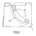
Figure 5 shows a further side view of one of the heads ofFigure 3 in which a guide means can be seen. - With reference to the aforesaid drawings, the
reference 100 indicates as a whole a module of a terminal (not shown) of an air-conditioning system for premises, for example a radiant element or plate or a heat exchanger. - The
module 100 comprises abody 110 insertable in a space in a wall, aseating 111 and a closure panel 112. The space is formed in the wall more or less roughly by a building worker by removing a portion of material from the wall or by constructing the wall around it. - The
insertable body 110 has the shape of a box or formwork and may be made of sheet metal or plastics material or of wood and is suitable for receiving the terminal of an air-conditioning system within it. - As can be seen in
Figure 2 , themodule 100 has afirst aperture 120 for the air entry and asecond aperture 121 for the air outlet. - Advantageously, in the
module 100 of the present invention it is possible to provide at least onehead 1 equipped with astructure 10 removably associated with themodule 100. Theseating 111 of themodule 100 is suitable for receiving one ormore heads 1 in positive connection. In this way it is possible to permit the complete replacement of thehead 1 according to requirements, in order to simplify, speed up and optimise the installation operations and/or any maintenance operations on themodule 100. - As can be seen in
Figure 3 , thestructure 10 comprises twoside walls rear wall 12 and a top wall, 13. - In order to regulate the flow of conditioned air from the terminal, the
structure 10 has afirst aperture 20 for the air entry, asecond aperture 21 for the air outlet and adeflector element 11 for intercepting the flow of air emerging from thesecond aperture 21. In particular, thedeflector element 11 extends in a predominant longitudinal direction X-X between the twoside walls - In the example shown in
Figure 3 , thesecond aperture 21 for the air outlet is positioned at the front of thehead 1. - It should be pointed out that, once the
head 1 is coupled to themodule 100, thesecond aperture 121 of themodule 100 for the air outlet is associated with thefirst aperture 20 of thehead 1 for the air entry in such a way as to obtain a circulation of air entering by thefirst aperture 120 of themodule 100 and emerging directly from thesecond aperture 21 of thehead 1. - The
head 1 comprises a guide means 50 associated with thestructure 10 for supporting and guiding the displacement of thedeflector element 11 between an open position and a closed position in which thedeflector element 11 substantially closes thesecond aperture 21. - Operationally associated with the
head 1 is a drive means 30 which, by means of a kinematic transmission means 70, is capable of actuating thedeflector element 11 between the open position and the closed position with respect to thestructure 10. - In one embodiment, the drive means 30 is associated with the
deflector element 11. In particular, thedeflector element 11 comprises afront side 11a facing towards the outside of thehead 1 when thedeflector element 11 is in the closed position, and an opposed rear side 11b. - In the example shown in
figure 4 , the drive means 30 is associated with the rear side 11b of thedeflector element 11 and is equipped with arotation shaft 31. - In more detail, the kinematic transmission means 70 comprises an assembly consisting of a
pinion 32 and arack 53. - Advantageously, the
pinion 32 is connected in a rotationally secure manner to therotation shaft 31 of the drive means 30, and therack 53 is integral with thestructure 10. In this way, when the drive means 30 transmits the motion to thepinion 32 this latter, since it is associated with therack 53, allows thedeflector element 11 to position itself in a plurality of positions between the open position, in which thedeflector element 11 allows the air flow to emerge from thesecond aperture 21, and the closed position, in which thedeflector element 11 interrupts the air flow emerging from thefirst aperture 20. - It should be noted that, by means of the
module 100 of the present invention, in which thedeflector element 11 can be positioned in a plurality of extremely precise positions, absolutely reliable and comfortable air-conditioning is ensured in the premises without the need for manual intervention for adjustment of the air-conditioning by a user. - As can be seen in the appended drawings, the guide means 50 is associated with the
side wall - The guide means 50 comprises a slot 51 in the inner surface 52 of which is associated the
rack 53 suitable for engaging with thepinion 32 for the actuation of thedeflector element 11. - Alternatively, the
rack 53 may be associated with both theside walls head 1 can be equipped with a plurality of drive means 30 for obtaining even finer positioning of thedeflector element 11. - The
module 100 comprises aconnecting means 80 suitable for connecting the drive means 30 to the mains network for the power supply. - Advantageously, the
head 1 comprises a supply means 40 for supplying the drive means 30, such as, for example, typical batteries. - In one embodiment, the supply means 40 is mounted on board the
head 1. - In an alternative embodiment, the supply means 40 is mounted on board the
deflector element 11. - As illustrated in
Figure 5 , thedeflector element 11 is equipped with an engagement means 60 coupled to the guide means 50. In particular, the engagement means 60 is equipped with sliding means 61 suitable for advancing in the guide means 60 during the movement of thedeflector element 11 into the plurality of positions from the open position to the closed position and/or vice versa. - For example, the
deflector element 11 may comprise at a first of its lateral ends a kinematic transmission means 70, and at a second of its ends, opposed to the first end, an engagement means 60 such as to ensure that thedeflector element 11 has effective stability during the movement. - According to one embodiment, the
module 100 is equipped with an acquisition means 200 for acquiring the temperature of the premises and suitable for transforming the measured temperature value t0 into an electrical signal e(t0) proportional to the measured temperature value t0. - In signal communication with the acquisition means 200, in the module 100 a control means 210 is provided which is suitable for comparing the measured temperature value t0 with a predetermined temperature value t1. The predetermined temperature value t1 is the value desired by the user and set for example on a common thermostat.
- The
module 100 moreover comprises a regulating means 220 in signal communication with the control means 210. The regulating means 220 is thus capable of sending a regulating signal to the drive means 30 for defining the orientation of thedeflector element 11 on the basis of the comparison between the measured temperature value t0 and the predetermined temperature value t1. - In order to regulate the temperature value desired by the user, the regulating means 220 is suitable for obtaining the predetermined and desired temperature value t1 in the premises.
- Advantageously, it is possible to provide for the acquisition means 200, the control means 210 and the regulating means 220 all to be housed in the
head 1. - In this way it is thus possible to obtain a
head 1 completely free of electrical connections with themodule 100 which houses it, resulting in extremely advanced operation even in the event of a lack of supply from the electrical mains. - Moreover, interventions by the specialised personnel may thus be even easier. It may even be possible, in the event of "off site" repairs, to completely replace the
head 1 which is to be repaired with another, issued by the maintenance body, in order thus to avoid interruptions in operation for the entire period during which the user's head will be undergoing repair. - In order to satisfy contingent and specific requirements, a person skilled in the art may apply to the above-described module and head according to the invention many modifications and variants, all, however, included within the scope of protection of the invention as defined by the appended claims.
Claims (14)
- A module (100) of a terminal (2) of an air-conditioning system for premises, characterized in that it comprises- a head (1) having a structure (10) removably associated with said module (100), said structure (10) comprising:- two side walls (14, 15), a rear wall (12) and a top wall (13),- a first aperture (20) for the air entry,- a second aperture (21) for the air outlet,- a deflector element (11) for intercepting the flow of air emerging from said second aperture (21), said deflector element (11) extending in a predominant longitudinal direction (X-X) between said two side walls (14, 15),- a guide means (50) associated with said structure (10) for supporting and guiding the displacement of said deflector element (11) between an open position and a closed position in which said deflector element (11) substantially closes said second aperture (21),- a drive means (30) operationally associated with said head (1) by means of a kinematic transmission means (70) for actuating said deflector element (11) between said open position and said closed position with respect to said structure (10).
- A module (100) according to claim 1, wherein said drive means (30) is associated with said deflector element (11).
- A module (100) according to claim 1 or claim 2, wherein:- said deflector element (11) comprises a front side (11a) facing towards the outside of said head (1) when said deflector element (11) is in said closed position, and an opposed rear side (11b), and wherein- said drive means (30) is associated with said rear side (11b) of said deflector element (11).
- A module (100) according to any one of claims 1 to 3, wherein said kinematic transmission means (70) comprises an assembly consisting of a pinion (32) and a rack (53).
- A module (100) according to claim 4 or claim 5, wherein said pinion (32) is connected in a rotationally secure manner to the rotation shaft (31) of said drive means (30) and said rack (53) is integral with said structure (10).
- A module (100) according to claim 5, wherein said guide means (50) is associated with said at least one side wall (14, 15), said guide means (50) comprising a slot (51) in the inner surface (52) of which is associated said rack (53) suitable for engaging with said pinion (32) for the actuation of said deflector element (11) in said plurality of positions between the open position and the closed position.
- A module (100) according to any one of claims 1 to 6, comprising a connecting means (80) suitable for connecting said drive means (30) to the mains network for the power supply.
- A module (100) according to any one of claims 1 to 6, wherein said head (1) comprises a supply means (40) for supplying said drive means (30).
- A module (100) according to claim 8, wherein said supply means (40) is mounted on board said deflector element (11).
- A module (100) according to any one of claims 1 to 9, wherein said deflector element (11) comprises an engagement means (60) coupled to said guide means (50), said engagement means (60) comprising a sliding means (61) suitable for advancing in the guide means (50) during the movement of said deflector element (11) in said plurality of positions between the open position and the closed position.
- A module (100) according to any one of claims 1 to 10, comprising:- an acquisition means (200) for acquiring the temperature of said premises, and suitable for transforming the measured temperature value (t0) into an electrical signal (e(t0)) proportional to said measured temperature value (t0),- a control means (210) in signal communication with said acquisition means (200) and suitable for comparing the value of said measured temperature (t0) with a predetermined temperature value (t1),- a regulating means (220) in signal communication with said control means (210) and suitable for sending a regulating signal to said drive means (30) for defining the orientation of said deflector element (11) on the basis of the comparison between said measured temperature value (t0) and said predetermined temperature value (t1), said regulating means (220) being suitable for obtaining said predetermined temperature value (t1) in said premises.
- A head (1) having a structure (10) comprising:- two side walls (14, 15), a rear wall (12) and a top wall (13),- a first aperture (20) for the air entry,- a second aperture (21) for the air outlet,- a deflector element (11) for intercepting the flow of air emerging from said second aperture (21), said deflector element (11) extending in a predominant longitudinal direction (X-X) between said two side walls (14, 15),- a guide means (50) associated with said structure (10) for supporting and guiding the displacement of said deflector element (11) between an open position and a closed position in which said deflector element substantially closes said second aperture (21),- a drive means (30) operationally associated with said head (1) by means of a kinematic transmission means (70) for actuating said deflector element (11) between said open position and said closed position with respect to said structure (10),characterized in that said head (1) can be associated with a module (100) according to any one of claims 1 to 11.
- A head (1) according to claim 12, wherein said acquisition means (200), said control means (210) and said regulating means (220) are housed in said structure 10.
- A head (10) according to claim 8 or claim 9, wherein said supply means (40) comprises at least one battery (41).
Priority Applications (1)
| Application Number | Priority Date | Filing Date | Title |
|---|---|---|---|
| EP08425124A EP2096364A1 (en) | 2008-02-29 | 2008-02-29 | Module of a terminal of an air-conditioning system for premises |
Applications Claiming Priority (1)
| Application Number | Priority Date | Filing Date | Title |
|---|---|---|---|
| EP08425124A EP2096364A1 (en) | 2008-02-29 | 2008-02-29 | Module of a terminal of an air-conditioning system for premises |
Publications (1)
| Publication Number | Publication Date |
|---|---|
| EP2096364A1 true EP2096364A1 (en) | 2009-09-02 |
Family
ID=39591840
Family Applications (1)
| Application Number | Title | Priority Date | Filing Date |
|---|---|---|---|
| EP08425124A Withdrawn EP2096364A1 (en) | 2008-02-29 | 2008-02-29 | Module of a terminal of an air-conditioning system for premises |
Country Status (1)
| Country | Link |
|---|---|
| EP (1) | EP2096364A1 (en) |
Cited By (1)
| Publication number | Priority date | Publication date | Assignee | Title |
|---|---|---|---|---|
| EP2835597A1 (en) * | 2013-08-02 | 2015-02-11 | Mitsubishi Heavy Industries, Ltd. | Air conditioner |
Citations (4)
| Publication number | Priority date | Publication date | Assignee | Title |
|---|---|---|---|---|
| EP0837288A1 (en) * | 1996-10-15 | 1998-04-22 | RIELLO CONDIZIONATORI S.p.A. | A fan convector with adjustable deflector elements |
| WO1999067577A1 (en) * | 1998-06-22 | 1999-12-29 | Springer Carrier S.A. | Oscillating drive for air flow discharge |
| WO2004003451A1 (en) * | 2002-06-26 | 2004-01-08 | Giordano Riello International Group S.P.A. | Heat convector with an electrically adjustable deflector element |
| WO2004092671A1 (en) * | 2003-04-16 | 2004-10-28 | Giordano Riello International Group S.P.A. | Electric motor power supply arrangement |
-
2008
- 2008-02-29 EP EP08425124A patent/EP2096364A1/en not_active Withdrawn
Patent Citations (4)
| Publication number | Priority date | Publication date | Assignee | Title |
|---|---|---|---|---|
| EP0837288A1 (en) * | 1996-10-15 | 1998-04-22 | RIELLO CONDIZIONATORI S.p.A. | A fan convector with adjustable deflector elements |
| WO1999067577A1 (en) * | 1998-06-22 | 1999-12-29 | Springer Carrier S.A. | Oscillating drive for air flow discharge |
| WO2004003451A1 (en) * | 2002-06-26 | 2004-01-08 | Giordano Riello International Group S.P.A. | Heat convector with an electrically adjustable deflector element |
| WO2004092671A1 (en) * | 2003-04-16 | 2004-10-28 | Giordano Riello International Group S.P.A. | Electric motor power supply arrangement |
Cited By (2)
| Publication number | Priority date | Publication date | Assignee | Title |
|---|---|---|---|---|
| EP2835597A1 (en) * | 2013-08-02 | 2015-02-11 | Mitsubishi Heavy Industries, Ltd. | Air conditioner |
| JP2015031452A (en) * | 2013-08-02 | 2015-02-16 | 三菱重工業株式会社 | Air conditioner |
Similar Documents
| Publication | Publication Date | Title |
|---|---|---|
| DE3532820A1 (en) | DEVICE FOR UNIFORM HEATING OF SPACES | |
| CN104697052A (en) | Indoor unit of air conditioner and control method of indoor unit of air conditioner | |
| EP2096364A1 (en) | Module of a terminal of an air-conditioning system for premises | |
| SE542661C2 (en) | Air terminal device for control of air flow in a ventilation system | |
| CN106152424A (en) | A kind of air volume controlled apparatus control method in air-conditioning | |
| US20150211764A1 (en) | Electric variable-air-volume diffuser | |
| EP3018426B1 (en) | Supply and exhaust air terminal device | |
| EP2096366A2 (en) | Terminal apparatus, e.g. ceiling diffuser, of a ventilation system | |
| JP3608182B2 (en) | Line-type outlet | |
| CN103148567A (en) | Feedback adjusting type air valve device | |
| CN115135083A (en) | Computer lab network monitoring device | |
| CN209966169U (en) | Ventilation device for installing embedded steaming and baking oven | |
| CN209459173U (en) | Air conditioner | |
| CN106403023A (en) | Cabinet air conditioner and air outlet control method thereof | |
| CN219160583U (en) | Cyclone air port adjusting structure | |
| US20170016641A1 (en) | Autonomous Airflow Regulation System for Heating or Cooling or Ventilation of Premises | |
| CN113154675A (en) | Air source heat pump air heater system | |
| CN217817071U (en) | Wall-mounted air conditioner indoor unit and air conditioner | |
| KR20100025301A (en) | Diffuser can wind direction controlling | |
| CN219014570U (en) | Air quantity adjusting device of heating ventilation air conditioner and heating ventilation air conditioner | |
| EP0863371B1 (en) | Ventilating Unit | |
| CN204373170U (en) | Horizontal blade detaching structure | |
| CN219756510U (en) | Air outlet structure of air conditioner | |
| CN201846000U (en) | Low-voltage switch cabinet | |
| CN213540803U (en) | Speed regulating device of direct current fan |
Legal Events
| Date | Code | Title | Description |
|---|---|---|---|
| PUAI | Public reference made under article 153(3) epc to a published international application that has entered the european phase |
Free format text: ORIGINAL CODE: 0009012 |
|
| AK | Designated contracting states |
Kind code of ref document: A1 Designated state(s): AT BE BG CH CY CZ DE DK EE ES FI FR GB GR HR HU IE IS IT LI LT LU LV MC MT NL NO PL PT RO SE SI SK TR |
|
| AX | Request for extension of the european patent |
Extension state: AL BA MK RS |
|
| AKX | Designation fees paid | ||
| REG | Reference to a national code |
Ref country code: DE Ref legal event code: 8566 |
|
| STAA | Information on the status of an ep patent application or granted ep patent |
Free format text: STATUS: THE APPLICATION IS DEEMED TO BE WITHDRAWN |
|
| 18D | Application deemed to be withdrawn |
Effective date: 20100614 |