EP2082246B1 - Cable fault detection - Google Patents
Cable fault detection Download PDFInfo
- Publication number
- EP2082246B1 EP2082246B1 EP07839762.7A EP07839762A EP2082246B1 EP 2082246 B1 EP2082246 B1 EP 2082246B1 EP 07839762 A EP07839762 A EP 07839762A EP 2082246 B1 EP2082246 B1 EP 2082246B1
- Authority
- EP
- European Patent Office
- Prior art keywords
- cable
- fault
- cable current
- current samples
- record data
- Prior art date
- Legal status (The legal status is an assumption and is not a legal conclusion. Google has not performed a legal analysis and makes no representation as to the accuracy of the status listed.)
- Active
Links
- 238000001514 detection method Methods 0.000 title description 26
- 238000000034 method Methods 0.000 claims description 19
- 230000005540 biological transmission Effects 0.000 claims description 10
- 230000009466 transformation Effects 0.000 claims description 3
- 238000005070 sampling Methods 0.000 claims description 2
- 230000001681 protective effect Effects 0.000 description 15
- 238000004458 analytical method Methods 0.000 description 13
- 238000004891 communication Methods 0.000 description 9
- 230000007246 mechanism Effects 0.000 description 8
- 230000015556 catabolic process Effects 0.000 description 7
- 238000009413 insulation Methods 0.000 description 6
- 230000000694 effects Effects 0.000 description 3
- 230000006870 function Effects 0.000 description 3
- 238000012544 monitoring process Methods 0.000 description 2
- 238000001556 precipitation Methods 0.000 description 2
- 241001465754 Metazoa Species 0.000 description 1
- 230000003466 anti-cipated effect Effects 0.000 description 1
- 238000013528 artificial neural network Methods 0.000 description 1
- 239000003990 capacitor Substances 0.000 description 1
- 238000006731 degradation reaction Methods 0.000 description 1
- 238000010586 diagram Methods 0.000 description 1
- 230000005611 electricity Effects 0.000 description 1
- 238000011156 evaluation Methods 0.000 description 1
- 238000010438 heat treatment Methods 0.000 description 1
- 238000012423 maintenance Methods 0.000 description 1
- 238000007726 management method Methods 0.000 description 1
- 238000010248 power generation Methods 0.000 description 1
- 230000011664 signaling Effects 0.000 description 1
- 230000002123 temporal effect Effects 0.000 description 1
- 238000012360 testing method Methods 0.000 description 1
- 230000001052 transient effect Effects 0.000 description 1
- 230000001960 triggered effect Effects 0.000 description 1
- 239000013598 vector Substances 0.000 description 1
Images

Classifications
-
- G—PHYSICS
- G01—MEASURING; TESTING
- G01R—MEASURING ELECTRIC VARIABLES; MEASURING MAGNETIC VARIABLES
- G01R31/00—Arrangements for testing electric properties; Arrangements for locating electric faults; Arrangements for electrical testing characterised by what is being tested not provided for elsewhere
- G01R31/50—Testing of electric apparatus, lines, cables or components for short-circuits, continuity, leakage current or incorrect line connections
- G01R31/58—Testing of lines, cables or conductors
Definitions
- the present application relates to fault detection in electrical power transmission and distribution systems. It finds particular application to the detection and analysis of faults in underground and other cables used in the transmission and distribution of electrical power.
- Underground and other cables are a key component in the transmission and distribution of electrical power.
- cables can be prone to shorts or otherwise abnormally low impedance connections between two or more phases or between one or more phases and ground.
- These and other cable faults can be caused by a number of factors, including human error (e.g., accidentally cutting or striking a cable), climatologic conditions (e.g., precipitation, seismic activity, or lightning strikes), animal activity, and failure or degradation of the cable or its associated equipment.
- human error e.g., accidentally cutting or striking a cable
- climatologic conditions e.g., precipitation, seismic activity, or lightning strikes
- One category of fault is that of self-clearing faults. While self-clearing faults can have any number of root causes, they typically have a temporal duration which is insufficient to trip the relevant protective device. In practice, the duration of most self-clearing faults is typically less than about two (2) to three (3) cycles of the power system frequency, and in many cases less than one (1) cycle.
- One mechanism which can generate self-clearing cable faults is a breakdown in the insulation between cable phases or between a cable phase and ground. Such faults are often caused or exacerbated by moisture at a cable splice or joint, and are typically characterized by an elevated or fault current having a duration of about one-quarter to one-half cycle (i.e., roughly four (4) to eight (8) milliseconds (mS) in a sixty Hertz (60 Hz) system). The onset of the fault current usually occurs at or near a voltage peak. As the situation deteriorates, the frequency and severity of these faults tend to worsen with time, culminating in an eventual cable failure and a resultant power outage.
- mS milliseconds
- a fault detection apparatus has been incorporated in a protective relay platform which can be used as an intelligent electronic device (IED).
- IED intelligent electronic device
- the apparatus Contemporaneously with detecting a current signal which exceeds a threshold value, the apparatus confirms that the circuit breaker did not operate and also evaluates succeeding current samples (again, contemporaneously with their occurrence) to determine whether duration of the fault is less than one (1) cycle. If these conditions are satisfied, the device increments a fault counter. If the number and/or frequency of such faults occurrences exceeds a certain setting, the apparatus initiates an alarm, signalization, and/or a trip. In an alternate implementation, the apparatus also determines whether the fault occurred near a voltage peak.
- the fault detection apparatus is provided at the level of the protective relay.
- SA substation automation
- DA distribution automation
- FA feeder automation
- the apparatus requires the use of a specialized hardware platform which must be closely coupled to the protective relay, and the detection techniques have been relatively unsophisticated.
- US patent No. 5,734,575 discloses a method for detecting and enabling the clearance of high impedance faults in an electrical transmission or distribution system.
- US patent application No. 2004/0036478 discloses a method for detecting a fault in a power line network, wherein the harmonic content and noise signature of the signal data are evaluated with reference to known fault signature data for detecting and identifying the location of an existing or anticipated fault.
- US patent application No. 2003/0125893 discloses a frequency domain reflectometer that is used in communication with a cable under test, in order to determine cable characteristics, such as the length of the cable.
- US patent No. 5,966,675 discloses a method for monitoring a power supply network by using a Discrete Fourier Transformation, wherein and the data are compressed using a threshold value.
- US patent No. 6,144,721 discloses a telephone line pair method for detecting and signaling line faults and the locations of such faults.
- US patent No. 6,798, 211 discloses a fault indicator that locates a fault in a power line by modeling pulses of reflected wave signals generated from electrical arcs.
- a method of analyzing a fault condition in a cable for the transmission and distribution of electrical power comprising:
- a tangible computer readable storage medium containing instructions which, when executed by a computer processor, cause the processor to carry out a method according to the annexed claims.
- a substation 100 includes a plurality of field devices 102, a substation intelligence system 104 and a communication interface 106.
- the field devices 102 include transformers, capacitors, circuit breakers, intelligent electronic devices (IEDs) and other equipment and assets as are typically encountered in the substation environment.
- the field devices 102 include one or more cables 160 such as transmission or feeder cables and associated protective devices 162.
- the field devices 102 are operatively connected to the substation intelligence system 104.
- the intelligence system 104 may function as one or more of a substation automation system, a feeder automation system, or a distribution automation system.
- the substation intelligence system 104 includes a server or other computer 105, a database 164, one or more client server components 166 and cable fault detection components 168, and an optional human machine interface (HMI) 109.
- HMI human machine interface
- the communication interface 106 connects the substation intelligence system 104 to a wide area network (WAN), the internet, or other communications network(s) 108.
- WAN wide area network
- the communication interface 106 connects the substation intelligence system 104 to a wide area network (WAN), the internet, or other communications network(s) 108.
- a supervisory control and data acquisition (SCADA) system 110 connects to the communications network 108 via suitable communications interface(s) 112.
- the SCADA system 110 is typically located remotely from the substation 100 and provides supervisory control functions for a plurality of substations 100 and/or other components of the power generation and distribution system.
- the substation intelligence system 104 may also be connected to one or more enterprise computer systems such as data warehouses, data marts, planning systems, geographic information systems (GIS), or centralized maintenance management systems (CMMS) 114, which are likewise connected to the communications network 108 through communication interfaces 116.
- enterprise computer systems such as data warehouses, data marts, planning systems, geographic information systems (GIS), or centralized maintenance management systems (CMMS) 114, which are likewise connected to the communications network 108 through communication interfaces 116.
- GIS geographic information systems
- CMMS centralized maintenance management systems
- the cables 160 may include one or more transmission or feeder cables.
- Transmission cables are typically used to transmit high-voltage electricity from a generation source or substation to another substation in the electric distribution system.
- Feeder cables are typically used to provide an electrical connection between the output of a substation and the input of downstream primary circuits. Feeder cables which leave the substation are sometimes termed substation exit cables.
- the cables 160 are not necessarily located within the physical boundaries of the substation 100 and may in fact be located some distance from the substation. Depending on siting and other considerations, some or all of the cable 160 may be underground cables.
- the protective devices 162 typically include one or more protective relays and associated circuit breakers or reclosers.
- the protective relays are advantageously implemented as IED-based devices which, among other functions, monitor the voltage, current, and other relevant parameters of their associated cables 160, for example to detect various fault conditions, such as those caused by current, voltage, and/or frequency disturbances and which may or may not be caused by a cable fault.
- the protective relay Upon detecting a fault condition, the protective relays capture digital fault record (DFR) data such as voltage, current, and other oscillographic data and set a DFR flag indicating the occurrence of the fault.
- DFR data is formatted for transmission in the known common format for transient data exchange (COMTRADE) or other suitable file format.
- COMTRADE transient data exchange
- the protective relay may also trip the associated breaker.
- the client/server components 166 are advantageously implemented as software or firmware modules which are stored in a memory or other computer readable storage medium accessible to the computer 105. Execution of the components 166 is typically driven by either a timer (timed polling) or trigger-based (interrupting) mechanism so as to operate substantially in real time. Thus, for example, a client/server component 166 may from time-to-time poll a particular protective device 162 to obtain information relating to its status.
- the client/sever component 166 obtains the DFR data from the protective device 162 and generates an alarm or fault log in which the DFR data is stored at an appropriate location in the database 166, again in the COMTRADE or other suitable format.
- receipt of a DFR flag from a protective device triggers acquisition of the DFR data and generation of the fault log.
- the cable fault detection component 168 is likewise implemented as a software or firmware module which is stored in a memory or other computer readable storage medium accessible to the computer 105.
- the component 168 is also executed by the computer 105 on a polled, triggered, or other suitable basis.
- the cable fault detection component 168 analyzes the DFR and/or other relevant input data to detect a signature associated with a cable fault. Upon detecting such a signature, the component 168 generates one or more outputs indicative of the fault for storage in the database 164.
- the HMI 109 which may be implemented in a software layer or otherwise in software which is distinct from that of the various components 166, 168, provides desired operator interface functionality, for example to allow a user to interact with the various modules 166, 168, the database 164, or other components of the substation intelligence system 104.
- the HMI 109 is implemented as software or other computer readable instructions which implement a graphical user interface (GUI) on a suitable computer.
- GUI graphical user interface
- User interfaces implemented in connection with the SCADA system 110 or the enterprise system 114, if any, may also allow a user to mine the data from one or more sources or otherwise provide desired HMI functionality.
- the input data 262 includes oscillographic record data 268 such as time and sample data vectors, the number of sampled data points in the oscillographic record 266, time stamp data 264 such as the date and time at which the record was acquired, the number and identification of the sampled signals 272 ( e.g., the number and identification of the sampled phase or phases), the system frequency 274, and other relevant data 292.
- oscillographic record data 268 such as time and sample data vectors
- time stamp data 264 such as the date and time at which the record was acquired
- the number and identification of the sampled signals 272 e.g., the number and identification of the sampled phase or phases
- system frequency 274 e.g., the number and identification of the sampled phase or phases
- the detection component 268 includes an analysis engine 288 which operates in conjunction with a Fourier processor 246, cable fault signature criteria 238, and alarm criteria 290.
- the Fourier transform processor 246, which is again advantageously implemented using suitable computer readable instructions, performs a discrete Fourier transform (DFT) of the voltage and/or current samples in the oscillographic record 268.
- DFT discrete Fourier transform
- the DFT is calculated over sample windows or time periods which begin at intervals corresponding to one quarter (1/4) cycle of the power system frequency and which have a duration corresponding to one half (1/2) cycle of the system frequency, although different window intervals and durations are also contemplated.
- performing a DFT of the time varying cable current samples generates frequency domain data indicative of the frequency component(s) of the cable current during a particular sampling window.
- the frequency domain data includes a peak at the power system frequency, the magnitude of which is indicative of the cable current during the period covered by the DFT.
- the cable fault signature 238 includes internal power system qualifiers 242 and optional external qualifiers 244 which are indicative of a cable fault.
- the internal qualifiers 242 include a threshold cable current value, a threshold fault duration, and a fault onset criterion, although additional or different qualifiers may also be considered.
- the external qualifiers 244 may include meteorological data such as precipitation, humidity, and/or ambient temperature.
- the alarm criteria 290 include those criteria which are used to signal an alarm condition.
- the alarm criteria may include a fault rate or frequency and/or a number of faults, although additional or different criteria are also contemplated.
- one or more of the cable fault signature 238 and alarm 290 criteria may be adjustable, for example by the user via a GUI implemented on the HMI 109 or otherwise.
- the analysis engine 288 evaluates the input data 262 to determine whether the fault satisfies the cable fault signature criteria 238. Again in the exemplary case of a cable fault caused by an insulation breakdown, the analysis engine 288 evaluates the Fourier transformed current signal to determine whether the magnitude of the cable current exceeds the threshold value. The analysis engine 288 also determines whether the duration of the fault is less than the threshold fault duration, whether the onset of the fault occurred at or near a voltage peak, and whether the fault was self-clearing. In an implementation which includes external qualifier(s) 244, the analysis engine 288 also evaluates the relevant other input data 292, for example to determine whether the relative humidity exceeds a desired value. Where the component 168 includes alarm criteria 290, the analysis engine also determines whether the desired alarm criteria have been satisfied, for example to determine whether the rate or frequency of the cable faults exceeds the specified fault rate.
- the cable fault detection component 168 uses the results of the evaluation to generate output data 276 such as one or more of a cable fault detected signal or flag 280, a cable fault rate or frequency 282, the number of cable faults 283, a cable fault alarm signal or flag 284, digital fault record data 286 such as the magnitude and duration of the fault, the phase or phase(s) affected by the fault 278, or other data 294.
- output data is advantageously stored as one or more points in the substation intelligence system database 164 together with a suitable time stamp.
- the detection component 168 may, alternatively or additionally, use other operational or non-operational data 262 as inputs to the cable fault analysis, with the cable fault signature criteria 238 selected accordingly.
- the sampled voltage waveform is also be considered, for example to determine whether a period of increased current is accompanied by a dip in the sampled voltage.
- the average current values may be considered as appropriate.
- other ambient or meteorological data such as lightning strikes, seismic activity, or the like may also be considered.
- the detection component 168 may also calculate a probability or likelihood that a particular cable fault results from a particular fault mechanism, for example by assigning relative weights to the various signature criteria 238.
- the detection component 168 may include or otherwise access an internal or external database containing empirically or heuristically derived cable fault signatures 238 indicative of various cable fault mechanisms.
- the cable fault output signal or flag 280 may also indicate the most likely fault mechanism or mechanisms. Separate outputs or flags may also be provided.
- the detection component 168 may be utilized in intelligence systems 104 such as those described in commonly-owned U.S. Patent Application Serial Number 11/555,393 by Stoupis, et al. , and entitled Electrical Substation Monitoring and Diagnostics, which application was filed on November 1, 2006.
- the detection component 168 advantageously operates on data having the COMTRADE or other desired format.
- the detection component 168 component may be executed on a computer or process other than the server computer.
- the detection component may be executed on a computer associated with the SCADA system 110 or the enterprise system 114, or otherwise on another suitable general purpose or dedicated processor which has access to the desired input data 262 over the communication network 118.
- Some or all of the component 168 may also be implemented in digital and/or analog hardware.
- the discrete Fourier transform may be implemented using a suitable fast Fourier transform (FFT) algorithm.
- FFT fast Fourier transform
- the analysis engine 288 may perform one or more of time-domain based, rule-based, neural network, expert system, analytical, or other suitable analyses.
- a fault is detected at step 302. More particularly to the exemplary implementation described above, a protective device 162 sets a DFR flag and generates DFR data in the COMTRADE or other suitable format.
- the DFR data is obtained at step 304.
- the DFR data is obtained by the intelligence system 104 and stored in the database 164 for use by the detection component 168.
- the input data 262 is obtained directly by the detection component 168.
- the DFR and other relevant input data is analyzed at step 306.
- the cable fault detection component 168 evaluates the input data to determine whether the input data is indicative of a cable fault.
- the detection component 168 considers signatures indicative of various cable fault mechanisms, the input data is evaluated against the various signatures.
- desired output data 276 such as one or more of a cable fault detection signal, cable fault number or rate, cable fault alarm, or cable fault mechanism output is generated.
- the output data 276 is stored in the database 164 or other desired location.
- step 310 the process is repeated, for example on a substantially real time basis during the operation of the power system.
Landscapes
- Physics & Mathematics (AREA)
- General Physics & Mathematics (AREA)
- Remote Monitoring And Control Of Power-Distribution Networks (AREA)
- Emergency Protection Circuit Devices (AREA)
Description
- The present application relates to fault detection in electrical power transmission and distribution systems. It finds particular application to the detection and analysis of faults in underground and other cables used in the transmission and distribution of electrical power.
- Underground and other cables are a key component in the transmission and distribution of electrical power. Unfortunately, however, cables can be prone to shorts or otherwise abnormally low impedance connections between two or more phases or between one or more phases and ground. These and other cable faults can be caused by a number of factors, including human error (e.g., accidentally cutting or striking a cable), climatologic conditions (e.g., precipitation, seismic activity, or lightning strikes), animal activity, and failure or degradation of the cable or its associated equipment. Moreover, cable faults can lead to power outages, which are inconvenient for the affected customers and which can be expensive for the electric utility involved.
- One category of fault is that of self-clearing faults. While self-clearing faults can have any number of root causes, they typically have a temporal duration which is insufficient to trip the relevant protective device. In practice, the duration of most self-clearing faults is typically less than about two (2) to three (3) cycles of the power system frequency, and in many cases less than one (1) cycle.
- One mechanism which can generate self-clearing cable faults is a breakdown in the insulation between cable phases or between a cable phase and ground. Such faults are often caused or exacerbated by moisture at a cable splice or joint, and are typically characterized by an elevated or fault current having a duration of about one-quarter to one-half cycle (i.e., roughly four (4) to eight (8) milliseconds (mS) in a sixty Hertz (60 Hz) system). The onset of the fault current usually occurs at or near a voltage peak. As the situation deteriorates, the frequency and severity of these faults tend to worsen with time, culminating in an eventual cable failure and a resultant power outage.
- As a consequence, a fault detection apparatus has been incorporated in a protective relay platform which can be used as an intelligent electronic device (IED). See Kojovic, et al., Sub-Cycle Overcurrent Protection for Self-Clearing Faults Due to Insulation Breakdown (1999);
U.S. Patent No. 6,198,401 to Newton, et al. , Detection or Sub-Cycle, Self-Clearing Faults, issued March 6, 2001. More particularly, and as more fully described in the references, the apparatus samples the cable current signal as it occurs. Contemporaneously with detecting a current signal which exceeds a threshold value, the apparatus confirms that the circuit breaker did not operate and also evaluates succeeding current samples (again, contemporaneously with their occurrence) to determine whether duration of the fault is less than one (1) cycle. If these conditions are satisfied, the device increments a fault counter. If the number and/or frequency of such faults occurrences exceeds a certain setting, the apparatus initiates an alarm, signalization, and/or a trip. In an alternate implementation, the apparatus also determines whether the fault occurred near a voltage peak. - However, the fault detection apparatus is provided at the level of the protective relay. One consequence of this relay-centric architecture is that the apparatus is relatively poorly integrated with the substation automation (SA), distribution automation (DA), feeder automation (FA), or other automation system. Moreover, the apparatus requires the use of a specialized hardware platform which must be closely coupled to the protective relay, and the detection techniques have been relatively unsophisticated.
-
US patent No. 5,734,575 discloses a method for detecting and enabling the clearance of high impedance faults in an electrical transmission or distribution system. -
US patent application No. 2004/0036478 discloses a method for detecting a fault in a power line network, wherein the harmonic content and noise signature of the signal data are evaluated with reference to known fault signature data for detecting and identifying the location of an existing or anticipated fault. -
US patent application No. 2003/0125893 discloses a frequency domain reflectometer that is used in communication with a cable under test, in order to determine cable characteristics, such as the length of the cable. -
US patent No. 5,966,675 discloses a method for monitoring a power supply network by using a Discrete Fourier Transformation, wherein and the data are compressed using a threshold value.US patent No. 6,144,721 discloses a telephone line pair method for detecting and signaling line faults and the locations of such faults. -
US patent No. 6,798, 211 discloses a fault indicator that locates a fault in a power line by modeling pulses of reflected wave signals generated from electrical arcs. - Aspects of the present application address these matters, and others.
- According to one aspect, a method of analyzing a fault condition in a cable for the transmission and distribution of electrical power, the method comprising:
- detecting the fault condition in the cable;
- upon detecting the fault condition in the cable, obtaining digital fault record data for the fault condition, the digital fault record data comprising oscillographic record data, and the oscillographic record data comprising cable current samples;
- performing a Fourier transform of the cable current samples in the oscillographic record data; and
- using the Fourier transformed cable current samples to determine whether the fault condition comprises a self-clearing fault, wherein the using of the Fourier transformed cable current samples comprises evaluating the Fourier transformed cable current samples to determine whether the fault condition satisfies cable fault signature criteria comprising internal power system qualifiers. The internal power system qualifiers comprise a threshold cable current value, and the evaluating the Fourier transformed cable current samples comprises determining whether the magnitude of the cable current exceeds the threshold cable current value
- According to another aspect, a tangible computer readable storage medium containing instructions which, when executed by a computer processor, cause the processor to carry out a method according to the annexed claims.
- Those skilled in the art will appreciate still other aspects of the present invention upon reading an understanding the attached figures and description.
- The present invention is illustrated by way of example and not limitation in the figures of the accompanying drawings, in which like references indicate similar elements and in which:
-
Figure 1 depicts components of an electrical power distribution system. -
Figure 2 depicts a substation intelligence system. -
Figure 3 depicts a cable fault detection module. - With reference to
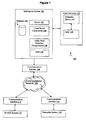
Figure 1 , asubstation 100 includes a plurality offield devices 102, asubstation intelligence system 104 and acommunication interface 106. Thefield devices 102 include transformers, capacitors, circuit breakers, intelligent electronic devices (IEDs) and other equipment and assets as are typically encountered in the substation environment. In the present example, thefield devices 102 include one ormore cables 160 such as transmission or feeder cables and associated protective devices 162. - The
field devices 102 are operatively connected to thesubstation intelligence system 104. Depending on the architecture of a given system, theintelligence system 104 may function as one or more of a substation automation system, a feeder automation system, or a distribution automation system. As illustrated, thesubstation intelligence system 104 includes a server orother computer 105, adatabase 164, one or moreclient server components 166 and cablefault detection components 168, and an optional human machine interface (HMI) 109. - The
communication interface 106 connects thesubstation intelligence system 104 to a wide area network (WAN), the internet, or other communications network(s) 108. - A supervisory control and data acquisition (SCADA)
system 110 connects to thecommunications network 108 via suitable communications interface(s) 112. The SCADAsystem 110 is typically located remotely from thesubstation 100 and provides supervisory control functions for a plurality ofsubstations 100 and/or other components of the power generation and distribution system. - The
substation intelligence system 104 may also be connected to one or more enterprise computer systems such as data warehouses, data marts, planning systems, geographic information systems (GIS), or centralized maintenance management systems (CMMS) 114, which are likewise connected to thecommunications network 108 throughcommunication interfaces 116. - As noted above, the
cables 160 may include one or more transmission or feeder cables. Transmission cables are typically used to transmit high-voltage electricity from a generation source or substation to another substation in the electric distribution system. Feeder cables are typically used to provide an electrical connection between the output of a substation and the input of downstream primary circuits. Feeder cables which leave the substation are sometimes termed substation exit cables. It should be noted, however, that thecables 160 are not necessarily located within the physical boundaries of thesubstation 100 and may in fact be located some distance from the substation. Depending on siting and other considerations, some or all of thecable 160 may be underground cables. - The protective devices 162 typically include one or more protective relays and associated circuit breakers or reclosers. The protective relays are advantageously implemented as IED-based devices which, among other functions, monitor the voltage, current, and other relevant parameters of their associated
cables 160, for example to detect various fault conditions, such as those caused by current, voltage, and/or frequency disturbances and which may or may not be caused by a cable fault. - Upon detecting a fault condition, the protective relays capture digital fault record (DFR) data such as voltage, current, and other oscillographic data and set a DFR flag indicating the occurrence of the fault. The DFR data is formatted for transmission in the known common format for transient data exchange (COMTRADE) or other suitable file format. Depending on the nature and severity of the fault, the protective relay may also trip the associated breaker.
- With ongoing reference to
Figure 1 , the client/server components 166 are advantageously implemented as software or firmware modules which are stored in a memory or other computer readable storage medium accessible to thecomputer 105. Execution of thecomponents 166 is typically driven by either a timer (timed polling) or trigger-based (interrupting) mechanism so as to operate substantially in real time. Thus, for example, a client/server component 166 may from time-to-time poll a particular protective device 162 to obtain information relating to its status. Where the protective device 162 has set a DFR flag, the client/severcomponent 166 obtains the DFR data from the protective device 162 and generates an alarm or fault log in which the DFR data is stored at an appropriate location in thedatabase 166, again in the COMTRADE or other suitable format. In the case of a trigger-based implementation, receipt of a DFR flag from a protective device triggers acquisition of the DFR data and generation of the fault log. - With still further reference to
Figure 1 , the cablefault detection component 168 is likewise implemented as a software or firmware module which is stored in a memory or other computer readable storage medium accessible to thecomputer 105. Thecomponent 168 is also executed by thecomputer 105 on a polled, triggered, or other suitable basis. As will be described in further detail below, the cablefault detection component 168 analyzes the DFR and/or other relevant input data to detect a signature associated with a cable fault. Upon detecting such a signature, thecomponent 168 generates one or more outputs indicative of the fault for storage in thedatabase 164. - The
HMI 109, which may be implemented in a software layer or otherwise in software which is distinct from that of thevarious components various modules database 164, or other components of thesubstation intelligence system 104. In one implementation, theHMI 109 is implemented as software or other computer readable instructions which implement a graphical user interface (GUI) on a suitable computer. User interfaces implemented in connection with theSCADA system 110 or theenterprise system 114, if any, may also allow a user to mine the data from one or more sources or otherwise provide desired HMI functionality. - A functional block diagram depicting an exemplary cable
fault detection component 168 in relation to itsinput 262 andoutput 276 data is shown inFigure 2 . Theinput data 262 includesoscillographic record data 268 such as time and sample data vectors, the number of sampled data points in the oscillographic record 266, time stamp data 264 such as the date and time at which the record was acquired, the number and identification of the sampled signals 272 (e.g., the number and identification of the sampled phase or phases), thesystem frequency 274, and otherrelevant data 292. - As illustrated, the
detection component 268 includes ananalysis engine 288 which operates in conjunction with aFourier processor 246, cablefault signature criteria 238, andalarm criteria 290. - The
Fourier transform processor 246, which is again advantageously implemented using suitable computer readable instructions, performs a discrete Fourier transform (DFT) of the voltage and/or current samples in theoscillographic record 268. In one implementation, the DFT is calculated over sample windows or time periods which begin at intervals corresponding to one quarter (1/4) cycle of the power system frequency and which have a duration corresponding to one half (1/2) cycle of the system frequency, although different window intervals and durations are also contemplated. As will be appreciated, performing a DFT of the time varying cable current samples generates frequency domain data indicative of the frequency component(s) of the cable current during a particular sampling window. The frequency domain data includes a peak at the power system frequency, the magnitude of which is indicative of the cable current during the period covered by the DFT. - The
cable fault signature 238 includes internalpower system qualifiers 242 and optionalexternal qualifiers 244 which are indicative of a cable fault. In the exemplary case of acable fault signature 238 associated with a self-clearing fault resulting from an insulation breakdown at a cable splice or joint, theinternal qualifiers 242 include a threshold cable current value, a threshold fault duration, and a fault onset criterion, although additional or different qualifiers may also be considered. Again in the case of a joint insulation breakdown, theexternal qualifiers 244 may include meteorological data such as precipitation, humidity, and/or ambient temperature. - The
alarm criteria 290 include those criteria which are used to signal an alarm condition. In the case of asignature 238 associated with an insulation breakdown, the alarm criteria may include a fault rate or frequency and/or a number of faults, although additional or different criteria are also contemplated. Note that one or more of thecable fault signature 238 andalarm 290 criteria may be adjustable, for example by the user via a GUI implemented on theHMI 109 or otherwise. - The
analysis engine 288 evaluates theinput data 262 to determine whether the fault satisfies the cablefault signature criteria 238. Again in the exemplary case of a cable fault caused by an insulation breakdown, theanalysis engine 288 evaluates the Fourier transformed current signal to determine whether the magnitude of the cable current exceeds the threshold value. Theanalysis engine 288 also determines whether the duration of the fault is less than the threshold fault duration, whether the onset of the fault occurred at or near a voltage peak, and whether the fault was self-clearing. In an implementation which includes external qualifier(s) 244, theanalysis engine 288 also evaluates the relevantother input data 292, for example to determine whether the relative humidity exceeds a desired value. Where thecomponent 168 includesalarm criteria 290, the analysis engine also determines whether the desired alarm criteria have been satisfied, for example to determine whether the rate or frequency of the cable faults exceeds the specified fault rate. - The cable
fault detection component 168 uses the results of the evaluation to generateoutput data 276 such as one or more of a cable fault detected signal orflag 280, a cable fault rate orfrequency 282, the number ofcable faults 283, a cable fault alarm signal orflag 284, digitalfault record data 286 such as the magnitude and duration of the fault, the phase or phase(s) affected by thefault 278, orother data 294. The output data is advantageously stored as one or more points in the substationintelligence system database 164 together with a suitable time stamp. - Various alternatives and extensions are also contemplated. For example, the
detection component 168 may, alternatively or additionally, use other operational ornon-operational data 262 as inputs to the cable fault analysis, with the cablefault signature criteria 238 selected accordingly. In one such implementation, the sampled voltage waveform is also be considered, for example to determine whether a period of increased current is accompanied by a dip in the sampled voltage. - If, as another example, heating caused by relatively higher values of cable current is expected to contribute to a cable fault, the average current values may be considered as appropriate. As still another example, other ambient or meteorological data such as lightning strikes, seismic activity, or the like may also be considered.
- The
detection component 168 may also calculate a probability or likelihood that a particular cable fault results from a particular fault mechanism, for example by assigning relative weights to thevarious signature criteria 238. Thedetection component 168 may include or otherwise access an internal or external database containing empirically or heuristically derivedcable fault signatures 238 indicative of various cable fault mechanisms. In such a case, the cable fault output signal orflag 280 may also indicate the most likely fault mechanism or mechanisms. Separate outputs or flags may also be provided. - The
detection component 168 may be utilized inintelligence systems 104 such as those described in commonly-ownedU.S. Patent Application Serial Number 11/555,393 by Stoupis, et al. - As noted above, the
detection component 168 advantageously operates on data having the COMTRADE or other desired format. Thus, thedetection component 168 component may be executed on a computer or process other than the server computer. For example, the detection component may be executed on a computer associated with theSCADA system 110 or theenterprise system 114, or otherwise on another suitable general purpose or dedicated processor which has access to the desiredinput data 262 over the communication network 118. Some or all of thecomponent 168 may also be implemented in digital and/or analog hardware. - Various alternative Fourier transform algorithms are also contemplated. According to one such alternative, the discrete Fourier transform may be implemented using a suitable fast Fourier transform (FFT) algorithm. While the above discussion has focused on an
analysis engine 288 which operates on frequency domain data, other analysis engines are contemplated. Thus, for example, theanalysis engine 288 may perform one or more of time-domain based, rule-based, neural network, expert system, analytical, or other suitable analyses. - Operation will now be described in relation to
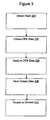
Figure 3 . A fault is detected atstep 302. More particularly to the exemplary implementation described above, a protective device 162 sets a DFR flag and generates DFR data in the COMTRADE or other suitable format. - The DFR data is obtained at
step 304. Thus, for example, the DFR data is obtained by theintelligence system 104 and stored in thedatabase 164 for use by thedetection component 168. Alternately, theinput data 262 is obtained directly by thedetection component 168. - The DFR and other relevant input data is analyzed at
step 306. As described above, for example, the cablefault detection component 168 evaluates the input data to determine whether the input data is indicative of a cable fault. In an implementation in which thedetection component 168 considers signatures indicative of various cable fault mechanisms, the input data is evaluated against the various signatures. Depending on the results of the analysis, desiredoutput data 276 such as one or more of a cable fault detection signal, cable fault number or rate, cable fault alarm, or cable fault mechanism output is generated. - At
step 308, theoutput data 276 is stored in thedatabase 164 or other desired location. - At
step 310, the process is repeated, for example on a substantially real time basis during the operation of the power system.
Claims (9)
- A method of analyzing a fault condition in a cable (160) for the transmission and distribution of electrical power, the method comprising:detecting (302) the fault condition in the cable (160);upon detecting the fault condition in the cable (160), obtaining (304) digital fault record data (DFR) for the fault condition, said digital fault record data comprising oscillographic record data (268), and said oscillographic record data comprising cable current samples;performing (306) a Fourier transform of said cable current samples in the oscillographic record data (268);the method characterized in that it comprises:using (306) the Fourier transformed cable current samples to determine whether the fault condition comprises a self-clearing fault;wherein said using the Fourier transformed cable current samples comprises evaluating the Fourier transformed cable current samples to determine whether the fault condition satisfies cable fault signature criteria (238), said cable fault signature criteria comprising internal power system qualifiers (242), and said internal power system qualifiers comprising a threshold cable current value; andwherein said evaluating the Fourier transformed cable current samples comprises determining whether the magnitude of the cable current exceeds said threshold cable current value.
- The method of claim 1, wherein said internal power system qualifiers (242) comprise a threshold fault duration, and wherein said evaluating the Fourier transformed cable current samples comprises determining whether the duration of the fault condition is less than said threshold fault duration.
- The method of claim 2, wherein said internal power system qualifiers (242) comprise a fault onset criterion, and wherein said evaluating the Fourier transformed cable current samples comprises determining whether the onset of the fault condition occurred at or near a voltage peak.
- The method of claim 3, wherein said cable fault signature criteria (238) comprise external qualifiers (244), said external qualifiers (244) comprising meteorological data.
- The method of claim 1, wherein said cable current samples comprise time varying cable current samples.
- The method of claim 5, wherein performing the Fourier transformation of said time varying cable current samples comprises generating frequency domain data indicative of frequency components of the cable (60) during a sampling window, said frequency domain data including a peak at the electrical power frequency, wherein the magnitude of said peak is indicative of the cable current during a period covered by the Fourier transformation.
- The method of claim 1, wherein said performing the Fourier transform comprises performing the Fourier transform also of voltage samples in said oscillagrophic record data (268).
- A tangible computer readable storage medium containing instructions which, when executed by a computer processor, cause the processor to carry out a method according one or more of claims 1-7.
- The tangible computer readable storage medium of claim 8, wherein the step of obtaining said digital fault record data includes obtaining the oscillographic record data from a substation automation system database.
Applications Claiming Priority (2)
| Application Number | Priority Date | Filing Date | Title |
|---|---|---|---|
| US11/555,429 US7672812B2 (en) | 2006-11-01 | 2006-11-01 | Cable fault detection |
| PCT/US2007/022543 WO2008057221A2 (en) | 2006-11-01 | 2007-10-24 | Cable fault detection |
Publications (3)
| Publication Number | Publication Date |
|---|---|
| EP2082246A2 EP2082246A2 (en) | 2009-07-29 |
| EP2082246A4 EP2082246A4 (en) | 2013-02-27 |
| EP2082246B1 true EP2082246B1 (en) | 2014-08-06 |
Family
ID=39329365
Family Applications (1)
| Application Number | Title | Priority Date | Filing Date |
|---|---|---|---|
| EP07839762.7A Active EP2082246B1 (en) | 2006-11-01 | 2007-10-24 | Cable fault detection |
Country Status (4)
| Country | Link |
|---|---|
| US (1) | US7672812B2 (en) |
| EP (1) | EP2082246B1 (en) |
| CN (1) | CN101627313B (en) |
| WO (1) | WO2008057221A2 (en) |
Families Citing this family (37)
| Publication number | Priority date | Publication date | Assignee | Title |
|---|---|---|---|---|
| US7672812B2 (en) | 2006-11-01 | 2010-03-02 | Abb Research Ltd. | Cable fault detection |
| US7725295B2 (en) | 2006-11-01 | 2010-05-25 | Abb Research Ltd. | Cable fault detection |
| US8078303B2 (en) * | 2007-07-03 | 2011-12-13 | Southwire Company | Electronic supervisor |
| CN102187539B (en) * | 2008-09-08 | 2015-05-27 | Abb研究有限公司 | Apparatus and method for adaptive fault detection in mv distribution circuits |
| US10324132B2 (en) | 2010-06-07 | 2019-06-18 | Abb Inc. | Systems and methods for power line event zone identification |
| US8675325B2 (en) * | 2010-10-20 | 2014-03-18 | Schneider Electric USA, Inc. | Electronic circuit breaker with alternate mode of operation using auxiliary power source |
| NO332207B1 (en) | 2010-10-28 | 2012-07-30 | Kongsberg Seatex As | Method and apparatus for fault analysis and redundancy switching in an energy supply for an instrumented towed cable in water |
| US8928489B2 (en) | 2011-02-08 | 2015-01-06 | Avista Corporation | Ping server |
| US8774975B2 (en) | 2011-02-08 | 2014-07-08 | Avista Corporation | Outage management algorithm |
| US8868360B2 (en) * | 2011-04-29 | 2014-10-21 | General Electric Company | System and device for detecting defects in underground cables |
| US8478900B2 (en) | 2011-05-18 | 2013-07-02 | Hewlett-Packard Development Company, L.P. | Determining misconnection of an electronic device to a network device using zone information |
| US9229036B2 (en) | 2012-01-03 | 2016-01-05 | Sentient Energy, Inc. | Energy harvest split core design elements for ease of installation, high performance, and long term reliability |
| US9182429B2 (en) | 2012-01-04 | 2015-11-10 | Sentient Energy, Inc. | Distribution line clamp force using DC bias on coil |
| CN104142441A (en) * | 2013-05-10 | 2014-11-12 | 中国飞机强度研究所 | Cable excitation detector for system loop |
| CN105092999B (en) * | 2014-05-19 | 2017-12-12 | 罗克韦尔自动化技术公司 | Positioned using the power quality events of multiple instructions |
| CN104299715B (en) * | 2014-10-15 | 2016-11-02 | 国网新疆电力公司哈密供电公司 | High intensity low-resistivity high voltage power transmission power cable |
| US9541586B2 (en) * | 2014-11-24 | 2017-01-10 | Rockwell Automation Technologies, Inc. | Capture of power quality information at the time a device fails |
| WO2016112104A1 (en) | 2015-01-06 | 2016-07-14 | Sentient Energy, Inc. | Methods and apparatus for mitigation of damage of power line assets from traveling electrical arcs |
| CN105353266B (en) * | 2015-09-28 | 2018-08-07 | 国网山东省电力公司济南供电公司 | A kind of cable fault monitoring method using buried cable fault monitoring system |
| US9984818B2 (en) | 2015-12-04 | 2018-05-29 | Sentient Energy, Inc. | Current harvesting transformer with protection from high currents |
| US10634733B2 (en) | 2016-11-18 | 2020-04-28 | Sentient Energy, Inc. | Overhead power line sensor |
| CN107808202A (en) * | 2017-10-27 | 2018-03-16 | 国家电网公司 | Electrical equipment fault judges guidance method and terminal device |
| US11476674B2 (en) | 2018-09-18 | 2022-10-18 | Sentient Technology Holdings, LLC | Systems and methods to maximize power from multiple power line energy harvesting devices |
| US11041915B2 (en) | 2018-09-18 | 2021-06-22 | Sentient Technology Holdings, LLC | Disturbance detecting current sensor |
| CN109471748A (en) * | 2018-11-05 | 2019-03-15 | 广州地铁集团有限公司 | A kind of Urban Rail Transit Signal mobile unit Intelligence Diagnosis method and device thereof |
| CN109738753A (en) * | 2018-12-07 | 2019-05-10 | 国网江苏省电力有限公司南京供电分公司 | A kind of detection method of grid failure state and fault type |
| US11125832B2 (en) | 2018-12-13 | 2021-09-21 | Sentient Technology Holdings, LLC | Multi-phase simulation environment |
| US11947374B2 (en) | 2019-02-04 | 2024-04-02 | Sentient Technology Holdings, LLC | Power supply for electric utility underground equipment |
| CN110007363B (en) * | 2019-05-13 | 2024-05-17 | 国网冀北电力有限公司承德供电公司 | Buried cable loss reporting system |
| CN110851670A (en) * | 2019-10-25 | 2020-02-28 | 袁茂银 | Underground cable fault repairing method and device |
| JP2022030808A (en) * | 2020-08-07 | 2022-02-18 | キヤノン株式会社 | Power reception device, control method thereof, and program |
| CN112345881A (en) * | 2020-09-29 | 2021-02-09 | 贵州电网有限责任公司 | Ring network power supply cable fault positioning system and method based on cloud platform |
| CN113093050B (en) * | 2021-03-31 | 2023-07-07 | 中国矿业大学 | Cable early fault identification method and system based on time-frequency characteristics of cable grounding wire current |
| CN113532621B (en) * | 2021-07-13 | 2023-10-20 | 国网浙江省电力有限公司 | Power cable monitoring and analyzing system and method based on edge calculation |
| CN114563661A (en) * | 2022-04-28 | 2022-05-31 | 国网山东省电力公司潍坊市寒亭区供电公司 | Power cable state monitoring method and device |
| CN115359748B (en) * | 2022-10-20 | 2023-02-10 | 武汉海微科技有限公司 | Yellow screen detection circuit and yellow screen detection method |
| CN117723892B (en) * | 2024-02-06 | 2024-05-28 | 西安博源电气有限公司 | Cable fault detection system |
Family Cites Families (22)
| Publication number | Priority date | Publication date | Assignee | Title |
|---|---|---|---|---|
| US4227145A (en) * | 1977-10-19 | 1980-10-07 | Bicc Limited | Apparatus for detecting faults in electric cables |
| US4254374A (en) * | 1979-04-02 | 1981-03-03 | Trihus Axicor T | Cable tester |
| US4446420A (en) * | 1982-01-28 | 1984-05-01 | Hydro Quebec | Method and device for detecting and locating fault and/or partial discharges in a gas-insulated electrical equipment |
| DE3812433A1 (en) * | 1988-04-14 | 1989-10-26 | Siemens Ag | Method for identifying the fault location on an electrical cable |
| JPH04324372A (en) * | 1991-04-25 | 1992-11-13 | Hitachi Ltd | Life pattern analysis and enunciation system |
| US5537327A (en) * | 1993-10-22 | 1996-07-16 | New York State Electric & Gas Corporation | Method and apparatus for detecting high-impedance faults in electrical power systems |
| DE4430246C2 (en) * | 1994-08-25 | 1997-08-28 | Siemens Ag | Method and arrangement for monitoring power supply networks |
| US7176589B2 (en) * | 1995-09-22 | 2007-02-13 | Input/Output, Inc. | Electrical power distribution and communication system for an underwater cable |
| US6144721A (en) | 1996-01-05 | 2000-11-07 | Communications Technology Corporation | Apparatus and method for line pair testing and fault diagnostics |
| US5886861A (en) * | 1997-09-15 | 1999-03-23 | Eaton Corporation | Apparatus providing response to arc faults in a power distribution cable protected by cable limiters |
| US6798211B1 (en) * | 1997-10-30 | 2004-09-28 | Remote Monitoring Systems, Inc. | Power line fault detector and analyzer |
| US6198401B1 (en) | 1999-02-12 | 2001-03-06 | Mcgraw Edison Company | Detection of sub-cycle, self-clearing faults |
| JP4040800B2 (en) * | 1999-08-04 | 2008-01-30 | 関西電力株式会社 | Single operation detector for distributed power supply |
| ES2320310T3 (en) * | 2000-03-10 | 2009-05-21 | Abb Schweiz Ag | METHOD AND DEVICE FOR EVALUATING THE STABILITY OF AN ELECTRICAL TRANSMISSION NETWORK. |
| US6868357B2 (en) * | 2001-07-07 | 2005-03-15 | Cynthia M. Furse | Frequency domain reflectometry system for testing wires and cables utilizing in-situ connectors, passive connectivity, cable fray detection, and live wire testing |
| US20030085715A1 (en) * | 2001-08-15 | 2003-05-08 | David Lubkeman | System and method for locating a fault on ungrounded and high-impedance grounded power systems |
| US6917888B2 (en) * | 2002-05-06 | 2005-07-12 | Arkados, Inc. | Method and system for power line network fault detection and quality monitoring |
| US6822457B2 (en) * | 2003-03-27 | 2004-11-23 | Marshall B. Borchert | Method of precisely determining the location of a fault on an electrical transmission system |
| CN100334458C (en) * | 2005-06-02 | 2007-08-29 | 昆明理工大学 | Malfunction route selection method for resonant grounded system based on current decomposition and wattles detection |
| RU2359383C1 (en) * | 2005-07-29 | 2009-06-20 | Американ Суперкондактор Корпорейшн | Monitoring short circuit of high temperature superconducting power cable |
| EP1850109A1 (en) * | 2006-04-24 | 2007-10-31 | ABB Research Ltd | Intelligent electronic device configuration verification |
| US7672812B2 (en) | 2006-11-01 | 2010-03-02 | Abb Research Ltd. | Cable fault detection |
-
2006
- 2006-11-01 US US11/555,429 patent/US7672812B2/en active Active
-
2007
- 2007-10-24 EP EP07839762.7A patent/EP2082246B1/en active Active
- 2007-10-24 WO PCT/US2007/022543 patent/WO2008057221A2/en active Application Filing
- 2007-10-24 CN CN2007800410470A patent/CN101627313B/en active Active
Also Published As
| Publication number | Publication date |
|---|---|
| CN101627313A (en) | 2010-01-13 |
| EP2082246A2 (en) | 2009-07-29 |
| CN101627313B (en) | 2013-12-11 |
| WO2008057221A2 (en) | 2008-05-15 |
| WO2008057221A3 (en) | 2009-08-27 |
| US20080100307A1 (en) | 2008-05-01 |
| US7672812B2 (en) | 2010-03-02 |
| EP2082246A4 (en) | 2013-02-27 |
Similar Documents
| Publication | Publication Date | Title |
|---|---|---|
| EP2082246B1 (en) | Cable fault detection | |
| US7725295B2 (en) | Cable fault detection | |
| Judd et al. | Partial discharge monitoring of power transformers using UHF sensors. Part I: sensors and signal interpretation | |
| US8174268B2 (en) | Protective relay monitoring system and method of comparing behavior patterns | |
| JP7394800B2 (en) | Transient-based fault localization method for ungrounded power distribution systems | |
| CN108828406A (en) | The fault recognition method and its system of non-intrusion type user power utilization | |
| US20110254557A1 (en) | Electromechanical relays including embedded sensors | |
| US20120077527A1 (en) | Network event identification and method of operation | |
| CN108008254A (en) | A kind of Failure Diagnosis of Substation Ground Network method and device | |
| US9188632B1 (en) | Self learning radio frequency monitoring system for identifying and locating faults in electrical distribution systems | |
| US11231999B2 (en) | Detection of electric power system anomalies in streaming measurements | |
| CN111551352A (en) | Method and system for detecting state of breaker of GIS (geographic information System) equipment | |
| WO2022105285A1 (en) | System and method for monitoring abnormal state on basis of impact event | |
| US11953534B2 (en) | Detection of lightning and related control strategies in electric power systems | |
| Napolitano et al. | Voltage transient measurements in a distribution network correlated with data from lightning location system and from sequence of events recorders | |
| Moghe et al. | Field investigation and analysis of incipient faults leading to a catastrophic failure in an underground distribution feeder | |
| CN104090211B (en) | A kind of online test method of distribution line high resistance earthing fault | |
| Song et al. | Power quality monitoring of single-wire-earth-return distribution feeders | |
| CN116840614A (en) | Cable line defect sensing and early warning method based on harmonic fluctuation characteristics | |
| CN102497025B (en) | Remote state monitoring method for automatic sectionalizer | |
| Henriques et al. | Proposal of fault prediction system for underground installations | |
| CN104977492A (en) | 10kV power distribution pole grounding state evaluation system and 10kV power distribution pole grounding state evaluation method | |
| Judd et al. | UHF diagnostic monitoring techniques for power transformers | |
| Küster et al. | An improved methodology for evaluation of lightning effects on distribution networks | |
| Hokazono et al. | Development of Predictive Fault Detection and Cause Estimation with Sensor-Equipped Sectionalizers in Advanced Distribution Automation System |
Legal Events
| Date | Code | Title | Description |
|---|---|---|---|
| PUAI | Public reference made under article 153(3) epc to a published international application that has entered the european phase |
Free format text: ORIGINAL CODE: 0009012 |
|
| 17P | Request for examination filed |
Effective date: 20090525 |
|
| AK | Designated contracting states |
Kind code of ref document: A2 Designated state(s): AT BE BG CH CY CZ DE DK EE ES FI FR GB GR HU IE IS IT LI LT LU LV MC MT NL PL PT RO SE SI SK TR |
|
| R17D | Deferred search report published (corrected) |
Effective date: 20090827 |
|
| RIC1 | Information provided on ipc code assigned before grant |
Ipc: G01R 31/08 20060101AFI20091113BHEP Ipc: G01R 31/02 20060101ALI20091113BHEP |
|
| DAX | Request for extension of the european patent (deleted) | ||
| RIN1 | Information on inventor provided before grant (corrected) |
Inventor name: LUBKEMAN, DAVID Inventor name: STOUPIS, JAMES Inventor name: MADWESH, AJAY C. |
|
| REG | Reference to a national code |
Ref country code: DE Ref legal event code: R079 Ref document number: 602007038015 Country of ref document: DE Free format text: PREVIOUS MAIN CLASS: G01R0031020000 Ipc: G01R0031080000 |
|
| A4 | Supplementary search report drawn up and despatched |
Effective date: 20130130 |
|
| RIC1 | Information provided on ipc code assigned before grant |
Ipc: G01R 31/08 20060101AFI20130124BHEP Ipc: G01R 31/02 20060101ALI20130124BHEP |
|
| GRAP | Despatch of communication of intention to grant a patent |
Free format text: ORIGINAL CODE: EPIDOSNIGR1 |
|
| INTG | Intention to grant announced |
Effective date: 20140225 |
|
| GRAS | Grant fee paid |
Free format text: ORIGINAL CODE: EPIDOSNIGR3 |
|
| GRAA | (expected) grant |
Free format text: ORIGINAL CODE: 0009210 |
|
| AK | Designated contracting states |
Kind code of ref document: B1 Designated state(s): AT BE BG CH CY CZ DE DK EE ES FI FR GB GR HU IE IS IT LI LT LU LV MC MT NL PL PT RO SE SI SK TR |
|
| REG | Reference to a national code |
Ref country code: GB Ref legal event code: FG4D |
|
| REG | Reference to a national code |
Ref country code: AT Ref legal event code: REF Ref document number: 681272 Country of ref document: AT Kind code of ref document: T Effective date: 20140815 Ref country code: CH Ref legal event code: EP |
|
| REG | Reference to a national code |
Ref country code: IE Ref legal event code: FG4D |
|
| REG | Reference to a national code |
Ref country code: DE Ref legal event code: R096 Ref document number: 602007038015 Country of ref document: DE Effective date: 20140918 |
|
| REG | Reference to a national code |
Ref country code: AT Ref legal event code: MK05 Ref document number: 681272 Country of ref document: AT Kind code of ref document: T Effective date: 20140806 |
|
| REG | Reference to a national code |
Ref country code: NL Ref legal event code: VDEP Effective date: 20140806 |
|
| REG | Reference to a national code |
Ref country code: LT Ref legal event code: MG4D |
|
| PG25 | Lapsed in a contracting state [announced via postgrant information from national office to epo] |
Ref country code: BG Free format text: LAPSE BECAUSE OF FAILURE TO SUBMIT A TRANSLATION OF THE DESCRIPTION OR TO PAY THE FEE WITHIN THE PRESCRIBED TIME-LIMIT Effective date: 20141106 Ref country code: ES Free format text: LAPSE BECAUSE OF FAILURE TO SUBMIT A TRANSLATION OF THE DESCRIPTION OR TO PAY THE FEE WITHIN THE PRESCRIBED TIME-LIMIT Effective date: 20140806 Ref country code: FI Free format text: LAPSE BECAUSE OF FAILURE TO SUBMIT A TRANSLATION OF THE DESCRIPTION OR TO PAY THE FEE WITHIN THE PRESCRIBED TIME-LIMIT Effective date: 20140806 Ref country code: LT Free format text: LAPSE BECAUSE OF FAILURE TO SUBMIT A TRANSLATION OF THE DESCRIPTION OR TO PAY THE FEE WITHIN THE PRESCRIBED TIME-LIMIT Effective date: 20140806 Ref country code: GR Free format text: LAPSE BECAUSE OF FAILURE TO SUBMIT A TRANSLATION OF THE DESCRIPTION OR TO PAY THE FEE WITHIN THE PRESCRIBED TIME-LIMIT Effective date: 20141107 Ref country code: PT Free format text: LAPSE BECAUSE OF FAILURE TO SUBMIT A TRANSLATION OF THE DESCRIPTION OR TO PAY THE FEE WITHIN THE PRESCRIBED TIME-LIMIT Effective date: 20141209 Ref country code: SE Free format text: LAPSE BECAUSE OF FAILURE TO SUBMIT A TRANSLATION OF THE DESCRIPTION OR TO PAY THE FEE WITHIN THE PRESCRIBED TIME-LIMIT Effective date: 20140806 |
|
| PG25 | Lapsed in a contracting state [announced via postgrant information from national office to epo] |
Ref country code: CY Free format text: LAPSE BECAUSE OF FAILURE TO SUBMIT A TRANSLATION OF THE DESCRIPTION OR TO PAY THE FEE WITHIN THE PRESCRIBED TIME-LIMIT Effective date: 20140806 Ref country code: PL Free format text: LAPSE BECAUSE OF FAILURE TO SUBMIT A TRANSLATION OF THE DESCRIPTION OR TO PAY THE FEE WITHIN THE PRESCRIBED TIME-LIMIT Effective date: 20140806 Ref country code: NL Free format text: LAPSE BECAUSE OF FAILURE TO SUBMIT A TRANSLATION OF THE DESCRIPTION OR TO PAY THE FEE WITHIN THE PRESCRIBED TIME-LIMIT Effective date: 20140806 Ref country code: AT Free format text: LAPSE BECAUSE OF FAILURE TO SUBMIT A TRANSLATION OF THE DESCRIPTION OR TO PAY THE FEE WITHIN THE PRESCRIBED TIME-LIMIT Effective date: 20140806 Ref country code: IS Free format text: LAPSE BECAUSE OF FAILURE TO SUBMIT A TRANSLATION OF THE DESCRIPTION OR TO PAY THE FEE WITHIN THE PRESCRIBED TIME-LIMIT Effective date: 20141206 Ref country code: LV Free format text: LAPSE BECAUSE OF FAILURE TO SUBMIT A TRANSLATION OF THE DESCRIPTION OR TO PAY THE FEE WITHIN THE PRESCRIBED TIME-LIMIT Effective date: 20140806 |
|
| PG25 | Lapsed in a contracting state [announced via postgrant information from national office to epo] |
Ref country code: CZ Free format text: LAPSE BECAUSE OF FAILURE TO SUBMIT A TRANSLATION OF THE DESCRIPTION OR TO PAY THE FEE WITHIN THE PRESCRIBED TIME-LIMIT Effective date: 20140806 Ref country code: IT Free format text: LAPSE BECAUSE OF FAILURE TO SUBMIT A TRANSLATION OF THE DESCRIPTION OR TO PAY THE FEE WITHIN THE PRESCRIBED TIME-LIMIT Effective date: 20140806 Ref country code: EE Free format text: LAPSE BECAUSE OF FAILURE TO SUBMIT A TRANSLATION OF THE DESCRIPTION OR TO PAY THE FEE WITHIN THE PRESCRIBED TIME-LIMIT Effective date: 20140806 Ref country code: SK Free format text: LAPSE BECAUSE OF FAILURE TO SUBMIT A TRANSLATION OF THE DESCRIPTION OR TO PAY THE FEE WITHIN THE PRESCRIBED TIME-LIMIT Effective date: 20140806 Ref country code: DK Free format text: LAPSE BECAUSE OF FAILURE TO SUBMIT A TRANSLATION OF THE DESCRIPTION OR TO PAY THE FEE WITHIN THE PRESCRIBED TIME-LIMIT Effective date: 20140806 Ref country code: RO Free format text: LAPSE BECAUSE OF FAILURE TO SUBMIT A TRANSLATION OF THE DESCRIPTION OR TO PAY THE FEE WITHIN THE PRESCRIBED TIME-LIMIT Effective date: 20140806 |
|
| REG | Reference to a national code |
Ref country code: DE Ref legal event code: R097 Ref document number: 602007038015 Country of ref document: DE |
|
| PG25 | Lapsed in a contracting state [announced via postgrant information from national office to epo] |
Ref country code: MC Free format text: LAPSE BECAUSE OF FAILURE TO SUBMIT A TRANSLATION OF THE DESCRIPTION OR TO PAY THE FEE WITHIN THE PRESCRIBED TIME-LIMIT Effective date: 20140806 Ref country code: LU Free format text: LAPSE BECAUSE OF FAILURE TO SUBMIT A TRANSLATION OF THE DESCRIPTION OR TO PAY THE FEE WITHIN THE PRESCRIBED TIME-LIMIT Effective date: 20141024 |
|
| REG | Reference to a national code |
Ref country code: CH Ref legal event code: PL |
|
| PLBE | No opposition filed within time limit |
Free format text: ORIGINAL CODE: 0009261 |
|
| STAA | Information on the status of an ep patent application or granted ep patent |
Free format text: STATUS: NO OPPOSITION FILED WITHIN TIME LIMIT |
|
| PG25 | Lapsed in a contracting state [announced via postgrant information from national office to epo] |
Ref country code: BE Free format text: LAPSE BECAUSE OF NON-PAYMENT OF DUE FEES Effective date: 20141031 |
|
| 26N | No opposition filed |
Effective date: 20150507 |
|
| REG | Reference to a national code |
Ref country code: IE Ref legal event code: MM4A |
|
| PG25 | Lapsed in a contracting state [announced via postgrant information from national office to epo] |
Ref country code: CH Free format text: LAPSE BECAUSE OF NON-PAYMENT OF DUE FEES Effective date: 20141031 Ref country code: LI Free format text: LAPSE BECAUSE OF NON-PAYMENT OF DUE FEES Effective date: 20141031 |
|
| REG | Reference to a national code |
Ref country code: FR Ref legal event code: PLFP Year of fee payment: 9 |
|
| PG25 | Lapsed in a contracting state [announced via postgrant information from national office to epo] |
Ref country code: IE Free format text: LAPSE BECAUSE OF NON-PAYMENT OF DUE FEES Effective date: 20141024 |
|
| PG25 | Lapsed in a contracting state [announced via postgrant information from national office to epo] |
Ref country code: SI Free format text: LAPSE BECAUSE OF FAILURE TO SUBMIT A TRANSLATION OF THE DESCRIPTION OR TO PAY THE FEE WITHIN THE PRESCRIBED TIME-LIMIT Effective date: 20140806 |
|
| PGFP | Annual fee paid to national office [announced via postgrant information from national office to epo] |
Ref country code: GB Payment date: 20151021 Year of fee payment: 9 Ref country code: DE Payment date: 20151022 Year of fee payment: 9 |
|
| PG25 | Lapsed in a contracting state [announced via postgrant information from national office to epo] |
Ref country code: BE Free format text: LAPSE BECAUSE OF FAILURE TO SUBMIT A TRANSLATION OF THE DESCRIPTION OR TO PAY THE FEE WITHIN THE PRESCRIBED TIME-LIMIT Effective date: 20140806 Ref country code: MT Free format text: LAPSE BECAUSE OF FAILURE TO SUBMIT A TRANSLATION OF THE DESCRIPTION OR TO PAY THE FEE WITHIN THE PRESCRIBED TIME-LIMIT Effective date: 20140806 Ref country code: HU Free format text: LAPSE BECAUSE OF FAILURE TO SUBMIT A TRANSLATION OF THE DESCRIPTION OR TO PAY THE FEE WITHIN THE PRESCRIBED TIME-LIMIT; INVALID AB INITIO Effective date: 20071024 Ref country code: TR Free format text: LAPSE BECAUSE OF FAILURE TO SUBMIT A TRANSLATION OF THE DESCRIPTION OR TO PAY THE FEE WITHIN THE PRESCRIBED TIME-LIMIT Effective date: 20140806 |
|
| REG | Reference to a national code |
Ref country code: FR Ref legal event code: PLFP Year of fee payment: 10 |
|
| REG | Reference to a national code |
Ref country code: DE Ref legal event code: R119 Ref document number: 602007038015 Country of ref document: DE |
|
| GBPC | Gb: european patent ceased through non-payment of renewal fee |
Effective date: 20161024 |
|
| PG25 | Lapsed in a contracting state [announced via postgrant information from national office to epo] |
Ref country code: DE Free format text: LAPSE BECAUSE OF NON-PAYMENT OF DUE FEES Effective date: 20170503 Ref country code: GB Free format text: LAPSE BECAUSE OF NON-PAYMENT OF DUE FEES Effective date: 20161024 |
|
| REG | Reference to a national code |
Ref country code: FR Ref legal event code: PLFP Year of fee payment: 11 |
|
| REG | Reference to a national code |
Ref country code: FR Ref legal event code: PLFP Year of fee payment: 12 |
|
| P01 | Opt-out of the competence of the unified patent court (upc) registered |
Effective date: 20230527 |
|
| PGFP | Annual fee paid to national office [announced via postgrant information from national office to epo] |
Ref country code: FR Payment date: 20231024 Year of fee payment: 17 |