EP2081039A2 - Detachable battery status alarm and battery detector thereof - Google Patents
Detachable battery status alarm and battery detector thereof Download PDFInfo
- Publication number
- EP2081039A2 EP2081039A2 EP08021691A EP08021691A EP2081039A2 EP 2081039 A2 EP2081039 A2 EP 2081039A2 EP 08021691 A EP08021691 A EP 08021691A EP 08021691 A EP08021691 A EP 08021691A EP 2081039 A2 EP2081039 A2 EP 2081039A2
- Authority
- EP
- European Patent Office
- Prior art keywords
- battery
- status
- alarm
- unit
- detector
- Prior art date
- Legal status (The legal status is an assumption and is not a legal conclusion. Google has not performed a legal analysis and makes no representation as to the accuracy of the status listed.)
- Granted
Links
- 230000002159 abnormal effect Effects 0.000 claims description 18
- 238000011084 recovery Methods 0.000 claims description 16
- 238000000034 method Methods 0.000 claims description 13
- 238000010998 test method Methods 0.000 claims description 8
- 239000002253 acid Substances 0.000 claims description 2
- QVGXLLKOCUKJST-UHFFFAOYSA-N atomic oxygen Chemical compound [O] QVGXLLKOCUKJST-UHFFFAOYSA-N 0.000 claims description 2
- 229910052760 oxygen Inorganic materials 0.000 claims description 2
- 239000001301 oxygen Substances 0.000 claims description 2
- 230000001276 controlling effect Effects 0.000 claims 1
- 230000001105 regulatory effect Effects 0.000 claims 1
- 238000010586 diagram Methods 0.000 description 6
- 238000012544 monitoring process Methods 0.000 description 5
- 230000009977 dual effect Effects 0.000 description 1
Images


Classifications
-
- G—PHYSICS
- G01—MEASURING; TESTING
- G01R—MEASURING ELECTRIC VARIABLES; MEASURING MAGNETIC VARIABLES
- G01R31/00—Arrangements for testing electric properties; Arrangements for locating electric faults; Arrangements for electrical testing characterised by what is being tested not provided for elsewhere
- G01R31/36—Arrangements for testing, measuring or monitoring the electrical condition of accumulators or electric batteries, e.g. capacity or state of charge [SoC]
- G01R31/385—Arrangements for measuring battery or accumulator variables
-
- G—PHYSICS
- G01—MEASURING; TESTING
- G01R—MEASURING ELECTRIC VARIABLES; MEASURING MAGNETIC VARIABLES
- G01R31/00—Arrangements for testing electric properties; Arrangements for locating electric faults; Arrangements for electrical testing characterised by what is being tested not provided for elsewhere
- G01R31/36—Arrangements for testing, measuring or monitoring the electrical condition of accumulators or electric batteries, e.g. capacity or state of charge [SoC]
- G01R31/364—Battery terminal connectors with integrated measuring arrangements
-
- G—PHYSICS
- G01—MEASURING; TESTING
- G01R—MEASURING ELECTRIC VARIABLES; MEASURING MAGNETIC VARIABLES
- G01R31/00—Arrangements for testing electric properties; Arrangements for locating electric faults; Arrangements for electrical testing characterised by what is being tested not provided for elsewhere
- G01R31/36—Arrangements for testing, measuring or monitoring the electrical condition of accumulators or electric batteries, e.g. capacity or state of charge [SoC]
- G01R31/3644—Constructional arrangements
- G01R31/3648—Constructional arrangements comprising digital calculation means, e.g. for performing an algorithm
-
- G—PHYSICS
- G01—MEASURING; TESTING
- G01R—MEASURING ELECTRIC VARIABLES; MEASURING MAGNETIC VARIABLES
- G01R31/00—Arrangements for testing electric properties; Arrangements for locating electric faults; Arrangements for electrical testing characterised by what is being tested not provided for elsewhere
- G01R31/36—Arrangements for testing, measuring or monitoring the electrical condition of accumulators or electric batteries, e.g. capacity or state of charge [SoC]
- G01R31/371—Arrangements for testing, measuring or monitoring the electrical condition of accumulators or electric batteries, e.g. capacity or state of charge [SoC] with remote indication, e.g. on external chargers
-
- H—ELECTRICITY
- H01—ELECTRIC ELEMENTS
- H01M—PROCESSES OR MEANS, e.g. BATTERIES, FOR THE DIRECT CONVERSION OF CHEMICAL ENERGY INTO ELECTRICAL ENERGY
- H01M10/00—Secondary cells; Manufacture thereof
- H01M10/42—Methods or arrangements for servicing or maintenance of secondary cells or secondary half-cells
- H01M10/48—Accumulators combined with arrangements for measuring, testing or indicating the condition of cells, e.g. the level or density of the electrolyte
-
- Y—GENERAL TAGGING OF NEW TECHNOLOGICAL DEVELOPMENTS; GENERAL TAGGING OF CROSS-SECTIONAL TECHNOLOGIES SPANNING OVER SEVERAL SECTIONS OF THE IPC; TECHNICAL SUBJECTS COVERED BY FORMER USPC CROSS-REFERENCE ART COLLECTIONS [XRACs] AND DIGESTS
- Y02—TECHNOLOGIES OR APPLICATIONS FOR MITIGATION OR ADAPTATION AGAINST CLIMATE CHANGE
- Y02E—REDUCTION OF GREENHOUSE GAS [GHG] EMISSIONS, RELATED TO ENERGY GENERATION, TRANSMISSION OR DISTRIBUTION
- Y02E60/00—Enabling technologies; Technologies with a potential or indirect contribution to GHG emissions mitigation
- Y02E60/10—Energy storage using batteries
Landscapes
- Physics & Mathematics (AREA)
- General Physics & Mathematics (AREA)
- Tests Of Electric Status Of Batteries (AREA)
- Secondary Cells (AREA)
- Primary Cells (AREA)
- Arrangements For Transmission Of Measured Signals (AREA)
- Alarm Systems (AREA)
- Charge And Discharge Circuits For Batteries Or The Like (AREA)
Abstract
Description
- The present invention relates to a battery tester, and more particularly to a detachable battery status alarm and at least one battery status detector thereof.
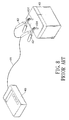
- With reference to
Fig. 8 , a conventional battery tester (40) is manually clipped to a battery (43) and detects and tests battery status. The battery tester (40) further has a wire (41) and two pairs of tongs (42). The wire (41) is connected to the pairs of the tongs (42). Since the battery (43) has a positive terminal (431) and a negative terminal (431), the two pairs of the tongs (42) are respectively clipped to the corresponding terminals (431). Therefore, a user operates buttons on the battery tester (40) to read and determine the current battery status. - Since one user only uses a battery tester (40) to test one battery (43), it will take longer to test multiple batteries. In addition, the user has to re-clip the terminals (431) of the battery (43).
- With further reference to
Fig. 9 , someone proposed a real time monitoring system for a battery set consisted of serial connecting battery units (541). A first example of the monitoring system has a remote computer (50), a single battery monitor (51) and a sensing module (53). The battery monitor (51) has multiple pairs of inputs connected to the corresponding battery unit (541) of the battery set (54). Therefore, the battery monitor (51) obtains the battery status of each battery unit (541). The battery monitor (51) is further connected to the sensing module (53) and the sensing module has a temperature sensor and a moisture sensor. Therefore, the battery monitor (51) obtains external status around the battery set (54). Since the battery monitor (51) is connected to the remote computer (50), the battery statuses and external status of the battery set will be further transmitted to the remote computer (50). Then the remote computer (50) stores and analyzes whether the battery unit is normal or not. However, if one battery unit (541) of the battery set (54) is damaged, the battery monitor does not obtain the battery statues of other normal battery unit (541) of the battery set (54). - With reference to
Fig. 10 , a second example of the monitoring system is used to monitor multiple battery sets (54), so further has more battery monitors (52) and more sensing modules (53). The battery monitors (51)(52) are connected in serial and one of the battery monitor (51) is connected to the remote computer (50). The battery monitor (51)(52) are connected to the corresponding battery set (54) to obtain the current battery statuses of the corresponding battery set (54). Further, each battery monitor (51)(52) is connected to the corresponding sensing module (53) and the sensing modules (53) are mounted next to the corresponding battery set (54). Therefore, each battery monitor (51)(52) further obtains external status of the corresponding battery set (54) through the sensing module (53). - Since the battery monitors (51)(52) are connected in serial, the battery monitor (51) connected to the remote computer (50) collects the battery statuses of other battery sets (54) through other battery monitors (52). Then the battery monitor (51) transmits the battery statuses of all battery sets (54) to the remote computer (50). However, the second example not only has the drawback of the first example, but also one of the battery monitor is damaged the battery monitor (51) connected to the remote computer (50) does not collect all battery statuses of the battery sets (54). Further, if the battery monitor (51) connected to the remote computer is damaged, other normal battery monitors (52) do not transmit battery statuses of the battery sets (54) to the remote computer (50).
- In addition, the battery units or battery sets are usually scattered at different places in a factory and it is difficult to connect the battery monitors and corresponding battery sets and the remote computer.
- The main objective of the present invention is to provide a detachable battery status alarm and at least one battery detector thereof that is easily mounted at the corresponding battery and immediately determines whether the battery or batteries is normal or not.
- The detachable battery status alarm in accordance with the present invention has an alarm device and at least one battery detector. The battery detector is directly mounted on the battery and electronically connected to the battery. The alarm device links to the battery detector to obtain the battery status in a physical connection or a wireless connection. Therefore, the alarm device does not physically connect to the battery or batteries to test the battery or batteries.
- Other objectives, advantages and novel features of the invention will become more apparent from the following detailed description when taken in conjunction with the accompanying drawings.
-
-
Fig. 1 is a perspective view of a first embodiment of a detachable battery status alarm connected to multiple individual batteries in accordance with the present invention; -
Fig. 2 is a perspective view of a second embodiment of a detachable battery status alarm connected to multiple individual batteries in accordance with the present invention; -
Fig. 3 is a perspective view of the battery status alarm connected to multiple serial connecting batteries in accordance with the present invention; -
Fig. 4A is a functional diagram of a battery detector of the detachable battery status alarm in accordance with the present invention; -
Fig. 4B is a detailed diagram ofFig. 4A ; -
Fig. 5A is a functional diagram of an alarm device of the detachable battery status alarm in accordance with the present invention; -
Fig. 5B is a detailed diagram ofFig. 5A ; -
Fig. 6 is a flow chart of a data communicating procedure applied to one alarm device to one battery detector; -
Fig. 7 A is a flow chart of a first example of a data communicating procedure applied to one alarm device to multiple battery detector; -
Fig. 7 B is a flow chart of a second example of a data communicating procedure applied to one alarm device to multiple battery detector; -
Fig. 8 is a perspective view of a conventional battery tester connected to a battery in accordance with the prior art; -
Fig. 9 is a block diagram of a first example of a battery monitoring system connected to multiple serial connecting batteries in accordance with the prior art; and -
Fig. 10 is a block diagram of a second example of a battery monitoring system connected to multiple serial connecting batteries in accordance with the prior art. - With reference to
Fig. 1 , a perspective view of a first embodiment of a battery status alarm has an alarm device (20) and at least one battery detector (10) separated from the alarm device (20). In the first embodiment of the detachable battery status alarm, three compact battery detectors (10) are electronically connected to the alarm device (20). - With further reference to
Fig. 4 A , the battery detectors (10) are respectively and electronically connected to the corresponding batteries (30). Each battery detector (10) has a casing (11), two electrode terminals (13) and a detecting and communicating circuit (12). The two electrode terminals (13) are mounted on the casing (11) and used to electronically connect to the positive and negative terminals (31) of the battery (30). The detecting and communicating circuit (12) is mounted inside the casing (11) and electronically connected to the two electrode terminals (13). Therefore, the detecting and communicating circuit (12) obtains a battery status of the battery (30) and transmits the battery status to the alarm device (20). - With further reference to
Fig. 5A , the alarm device (20) links to each battery detector (10) to dual-communicate with each battery detector (10). In the first embodiment, the alarm device (20) is physically connected to each battery detector (10). The alarm device (20) has a shell (21) and a communicating and alarm circuit (21). The communicating and alarm circuit (21) receives and stores the battery statuses from the battery detectors (10). The communicating and alarm circuit (21) further determines whether the battery statuses are abnormal. If the battery status is abnormal, the communicating and alarm circuit (21) alarms the operator. - With reference to
Fig. 2 , the second embodiment of the battery detector (10) is similar to the first embodiment, but the alarm device (20) wireless communicates with the battery detector (10) in a dual way. - With reference to
Fig. 3 , each compact battery detector (10) is directly and electronically to the corresponding battery (30) and the multiple batteries (30) are freely to connect in serial or separate from each other. Therefore, the present invention is also applied to a battery set consisted of multiple battery units connected in serial. - With reference to
Figs. 4A and4B , the detecting and communicating circuit (12) of the battery detector (10) has a power detecting unit (121), an environment status detector (122), a first processing unit (123) and a first communicating unit (124). - The power detecting unit (121) has a resistor load and an electrical switch. The resistor load is selectively and electronically connected to the two electrode terminals (13) through the electrical switch. In the first embodiment, the power detecting unit (121) further has a power regulator (125) electronically connected to the two electrode terminals (13). The power regulator (125) regulates a voltage of the battery to a DC voltage, and then outputs the DC voltage as power source. Therefore, the battery detector (10) does not require an external power source.
- The environment status detecting unit (122) has an environment sensor such as a pressure sensor, a temperature sensor, a hygrometer, an acid and alkaline detector or an oxygen sensor. The environment status detecting unit (122) is mounted next to the corresponding battery (30).
- The first processing unit (123) is electronically connected to the power detecting unit (121) and the environment status detector (122) and has a test procedure. The first processing unit (123) obtains the DC voltage to operate from the power regulator (125) of the power detecting unit (121). The first processing unit (123) executes the test procedure to control the electronic switch, so the resistor load is selectively and electronically connected to the battery (30). Then the first processing unit (123) obtains the power data of the battery (30) and then converts the power data to current battery status. The first processing unit (123) may be a microprocessor or a single chip.
- The first communicating unit (124) is electronically connected to the first processing unit (123) and receives and converts the battery status in a specific format. Then the converted battery status is transmitted to the alarm device (20) in a physical connection or a wireless connection. The physical communicating module may be RS-232, USB or RJ-45 and the wireless communicating module may be a bluetooth, RF or IR etc. In the second embodiment, the first communicating unit (124) is a RF communicating module.
- Based on foregoing description, the first processing unit (123) obtains the current battery status and the environment status of the corresponding battery (30). The first processing unit (123) further transmits the battery status and the environment status to the alarm device (20) through the first communicating device (124).
- With reference to
Figs. 5A and5B , the communicating and alarm circuit (21) of the alarm device (20) has a second communicating unit (211), a second processing unit (212), an output unit (123) and an input unit (124). - The second communicating unit (211) links to the first communicating units (124) of the battery detectors (10) to receive battery statuses and environment statuses for the batteries (30). In the second embodiment, the second communicating unit (211) is a RF communicating module.
- The second processing unit (212) is electronically connected to the second communicating unit (211) to receive the battery statuses and environment statuses. The second processing unit (212) has an alarm procedure. When the second processing unit (212) executes the alarm procedure, the second processing unit (212) determines whether the battery statuses or the environment statuses are abnormal.
- The output unit (213) is electronically connected to outputs of the second processing unit (212), so the second processing unit (212) outputs the battery statuses and environment statuses for the batteries (30) to the output unit (213). The output unit (213) outputs the battery statuses and environment statuses in different audio or visible format. The output unit (213) may be a display, a printer, a buzzer or light indicators etc devices. Further, the output unit (213) alarms to the operator when the second processing unit (212) determines that the battery statuses or environment statuses are abnormal. In the preferred embodiment, the output unit (213) is a LCD display.
- The input unit (215) is electronically connected to input of the second processing unit (212) and may be a keyboard or a mouse etc. device. Therefore, the input unit (215) is used to set parameters of the second processing unit (212).
- The communicating and alarm circuit (21) has a connecting port (215) such as an RS-232, RJ45, Bluetooth, RF, UART, USB, I2C or IR etc. The connecting port (215) is used to connect an external device, such as a computer.
- Based on the foregoing description, the second processing unit (212) obtains the battery statuses and environment statuses of all batteries (30) and further determines whether the output unit (213) alarms to the operator. Further, the second processing unit (212) outputs the battery statuses and environment statuses to the computer through the connecting port (215). Therefore, a remote computer can be connected to the alarm device (20) to obtain, store and analyze the battery statuses and environment statuses.
- With further reference to
Fig. 6 , a data communicating procedure between the alarm device and a signal battery detector is further explained as follow. - The alarm device (20) first recognizes all battery detectors (10) by a handshake connecting process. The alarm device (20) transmits a response request including a battery detector identification (ID) and an alarm device identification (ID) to the battery detector (10). When the battery detector (10) receives the response request, the battery detector (10) checks whether the battery detector ID is correct or not. If the battery detector (10) does not match the battery detector ID preset inside the battery detector (10), the battery detector (10) does not response the response request. If the battery detector ID is correct, the battery detector (10) sends the battery status, the environment status and a battery detector ID to the alarm device (20). At the time, the alarm device (20) outputs the battery status and environment status to the output unit (213) and further determines whether the battery status or the environment status is abnormal. If the determining result is positive, the output unit (213) further alarms the alarm device operator. Since the compact battery detector (10) is directly connected to the battery (30), the alarm device (20) does not physically connected to the battery (30) to test the battery status. Further, the alarm device (20) also outputs the battery status and the environment status to the computer and the computer stores the battery status and the environment status.
- In the first embodiment, the alarm device (20) automatically executes the above data communicating procedure and cyclically obtains the battery status and the environment status. The operator also uses the input device (214) to control whether the data communicating procedure is executed or not.
- With reference to
Fig. 7A , another data communicating procedure between the alarm device (20) and two battery detectors (10) is further explains as follow. - The alarm device (20) first recognizes all battery detectors (10) by a handshake connecting process. The alarm device (20) transmits a response request including a first battery detector ID and the alarm device ID. The request response will be received the first and second battery detectors (10, 10a), but only the first battery detector (10) will including a first battery detector ID and the alarm device ID. The request response will be received the first and second battery detectors (10, 10a), but only the first battery detector (10) will send the battery status and the environment status of the corresponding battery to the alarm device (20) since the first battery detector ID of the response request matches the own battery detector ID of the first battery detector (10). The alarm device (20) drives the display to display the received the battery status and the environment status of the corresponding battery. At the time, the alarm device (20) also determines whether the battery status and the environment status of the corresponding are abnormal or not. If the determining result is positive, the alarm device (20) alarms to the operator.
- The alarm device (20) transmits a next response request including a second battery detector ID and the alarm device ID. The request response will be received the first and second battery detectors (10, 10a), but only the second battery detector (10a) will send the battery status and the environment status of the corresponding battery to the alarm device (20) since the second battery detector ID of the response request matches the own battery detector ID of the second battery detector (10a). The alarm (20) also displays them on the display and determines whether they are abnormal or not.
- Therefore, the alarm device (20) automatically links to each battery detector (10) and select a specific battery detector (10, 10a) to response the current battery status and the environment status of the corresponding battery. The alarm device (20) obtains all battery statues and environment status of the batteries (30) through the battery detectors (10) on the corresponding batteries (30). The alarm device (20) does not physically connected to the batteries (20) one by one, the battery status and the environment status of each battery (30) will be obtained. Then the alarm device (20) determines whether the battery status or the environment status of each battery (30) is abnormal. Since the alarm device (20) obtains the battery detector ID, the abnormal status of the specific battery detector (10) will be output to the output unit (213) to alarm the operator. The operator clearly understands which one battery (30) is abnormal now.
- With reference to
Fig. 7B , another data communicating procedure between one alarm device (20) and multiple battery detectors (10) is further described as follow. The battery detectors (10) first respectively transmit the connecting requests to the alarm device (20). If the alarm device (20) first received the connecting request of the first battery detector (10), the alarm device (20) sends an allowable connecting response to the first battery detector (10). Then the first battery detector (10) sends the battery status and the environment status to the alarm device (20). When the alarm device (20) successfully received the battery status and the environment status of the first battery detector (10) and then receives a connecting request from the second battery detector (10), the alarm device (20) sends an allowable connecting response to the second battery detector (10). The second battery detector (10) transmits the battery status and the environment status to the alarm device (20) after the allowable connecting response is received. Therefore, each battery detector (10) automatically requests to link to the alarm device (20) and transmits the battery status and environment status to alarm device (20). - In addition, the test procedure of the first processing unit of the battery detector (10) has following steps of:
- (a) obtaining an initial voltage of a the battery;
- (b) applying the resistor load to the battery for a first time period of 0.1 milliseconds to one second;
- (c) measuring a first voltage at the end of the first time period;
- (d) removing the resistor load;
- (e) measuring a second voltage at the end of a first recovery time period after removing the resistor load;
- (f) measuring a third voltage at the end of a second recovery time period after removing the resistor load; and
- (g) analyzing the condition of the battery.
- An internal resistance of the battery is calculated according to the equation: Ri=(V4-V2)/(V2/Rload) where Rload is the resistor load and Ri is the internal resistance. The internal resistance of the battery is used to calculate the capacity of the battery. The measured voltages also are used to determine whether the battery passes or fails. Whether the battery passes the test can be determined by calculating the capacity of the battery and comparing with the input capacity. If the calculated capacity is greater than a predetermined percentage of the input capacity, for example, ninety percent, the battery passes the test. If a difference between the third voltage and the second voltage (V4-V3) is greater than a predetermined voltage, for example, 100 millivolts, then the battery passes the test. If difference between the third voltage and the second voltage (V4-V3) is less than the predetermined voltage then the battery fails the test. If the battery fails the test, then the battery detector re-executes the test procedure. If the test is not passed again, after a recharge, then the battery status is abnormal.
- The second recovery time is longer than the first recovery time period and the second time period is longer than the first time period. The first time period may be 0.1 ms to 1s or 1ms. The first recovery time period may be 0.2ms to 1s or 0.5ms to 5s. The second recovery time period may be 0.6ms to 10s or 60ms to 100s.
- In addition, the first processing unit further obtains or calculates the battery voltage, the battery current, the cold cranking ampere (CCA), the ampere-hour(AH), the cranking amps (CA), the marine cranking ampere (MCA), charge status, watt-hour (WH).
- Based on the foregoing description, the detachable battery status alarm in accordance with the present invention may be applied to monitor single battery or multiple battery. Since the compact battery detector is directly mounted on the battery and electronically connected to the battery, the alarm device obtains the battery status through the compact battery detector without physical connecting with the battery. Further, if one battery of the serial connecting batteries is damaged, the alarm device still obtains the battery statuses of other batteries.
- Even though numerous characteristics and advantages of the present invention have been set forth in the foregoing description, together with details of the structure and function of the invention, the disclosure is illustrative only. Changes may be made in detail, especially in matters of shape, size, and arrangement of parts within the principles of the invention to the full extent indicated by the broad general meaning of the terms in which the appended claims are expressed.
Claims (15)
- A detachable battery status alarm comprising:at least one battery detector (10) having:a casing (11);two electrode terminals (13) mounted on the casing (11) and adapted to electronically connected to a battery (30); anda detecting and communicating circuit (12) mounted inside the casing (11), electronically connected to the two electrode terminals (13) to obtain a battery status of the battery (30) and then output the battery status; andan alarm device (20) linking to each of the at least one battery detector (10), dual-communicating with the battery detector (10) and having:a shell (21); anda communicating and alarm circuit (21) mounted inside the shell (21), receiving and storing the battery statuses from each of the at least one battery detector (10), and determining whether the battery statuses are abnormal; if a determining result positive, the communicating and alarm circuit (21) alarms.
- The detachable battery status alarm as claimed in claim 1, wherein the detecting and communicating circuit (12) comprises:a power detecting unit (121) having:an electronic switch; anda resistor load electronically connected to the two electrode terminals through the electronic switch and adapted to selectively connected to the battery;a first processing unit (123) electronically connected to the power detecting unit (121) and has a test procedure to control the electronic switch to turn on or turn off, and then the resistor load selectively connected to the two electrode terminals (13);a first communicating unit (124) electronically connected to the first processing unit (123) and transmitting the battery status to the alarm device (20);a power regulator (125) electronically connected to the two electrode terminals (13), regulating a voltage of the battery and then outputting a DC voltage to the first processing unit (123), the first communicating unit (124) and power detecting unit (121).
- The detachable battery status alarm as claimed in claim 2, wherein the test procedure has steps of:(a) obtaining an initial voltage of the battery (30);(b) applying the resistor load to the battery (30) for a first time period;(c) measuring a first voltage at the end of the first time period;(d) removing the resistor load;(e) measuring a second voltage at the end of a first recovery time period after removing the resistor load;(f) measuring a third voltage at the end of a second recovery time period after removing the resistor load; and(g) analyzing the condition of the battery having acts of:(g1) calculating an internal resistance of the battery by an equation: Ri=(V4-V2)/(V2/Rload), wherein Ri is the internal resistance and Rload is the resistor load;(g2) calculating a current capacity of the battery by the internal resistance;(g3) determining whether the current capacity of the battery is greater than a preset capacity; if a determining result is positive, the battery is normal and on the contrary, the battery is abnormal; and(g4) determining a difference between the third voltage and the second voltage is greater than a preset voltage; if a determining result is positive, the battery is normal and on the contrary, the battery (30) is abnormal.
- The detachable battery status alarm as claimed in claim 3, wherein the second recovery time is longer than the first recovery time period and the second time period is longer than the first time period.
- The detachable battery status alarm as claimed in claim 4, wherein the first time period is 0.1ms to 1s or 1ms, the first recovery time period is 0.2ms to 1s or 0.5ms to 5s and the second recovery time period is 0.6ms to 10s or 60ms to 100s.
- The detachable battery status alarm as claimed in claim 3, further comprising an environment status detecting unit (122) electronically connected to the first processing unit (123), adapted to mount next to the battery (30), wherein the first processing unit (123) obtains an environment status of the battery (30) through the environment status detecting unit (122).
- The detachable battery status alarm as claimed in claim 6, wherein the communicating and alarm circuit (21) of the alarm unit (20) comprises:a second communicating unit (211) linking to the first communicating unit (124) of each of the at least one battery detector (10) to receive the battery statuses and environment statuses;a second processing unit (212) electronically connected to the second communicating unit (211) to receive the battery status and environment statuses, and having inputs, outputs and an alarm procedure to determine whether the battery status or environment is abnormal;an output unit (213) electronically connected to the outputs of the second processing unit (212), so the second processing unit (212) outputs the battery statuses or environment statuses to the output unit (213), and controlling the output unit (213) to alarm after the battery status or environment status is abnormal; andan input unit (214) electronically connected to the inputs of the second processing unit (212) to set parameters of the second processing unit (212).
- The detachable battery status alarm as claimed in claim 7, wherein
the output unit (213) is a display, a printer, a buzzer or a light indicator; and
the input unit (214) is a keyboard or a mouse. - The detachable battery status alarm as claimed in claim 7, wherein the alarm device (20) further comprises a connecting port (215) electronically connected to the second processing unit (212) and adapted to connect to an external device.
- The detachable battery status alarm as claimed in claim 8, wherein the first and second communicating units (124) (211) are physically connected or wireless connected to each other.
- A compact battery detector (10), comprising:a casing (11);two electrode terminals (13) mounted on the casing (11) and adapted to electronically connected to a battery (30); anda detecting and communicating circuit (12) mounted inside the casing (11), electronically connected to the two electrode terminals (13) to obtain a battery status of the battery and then output the battery status.
- The compact battery detector as claimed in claim 1, wherein the detecting and communicating circuit (12) comprises:a power detecting unit (121) having:an electronic switch; anda resistor load electronically connected to the two electrode terminals through the electronic switch and adapted to selectively connected to the battery;a first processing unit (123) electronically connected to the power detecting unit (121) and has a test procedure to control the electronic switch to turn on or turn off, and then the resistor load selectively connected to the two electrode terminals (13); anda first communicating unit (124) electronically connected to the first processing unit (123).
- The compact battery detector as claimed in claim 12, wherein the test procedure has steps of:(a) obtaining an initial voltage of the battery (30);(b) applying the resistor load to the battery (30) for a first time period;(c) measuring a first voltage at the end of the first time period;(d) removing the resistor load;(e) measuring a second voltage at the end of a first recovery time period after removing the resistor load;(f) measuring a third voltage at the end of a second recovery time period after removing the resistor load; and(g) analyzing the condition of the battery (30) having acts of:(g1) calculating an internal resistance of the battery (30) by an equation: Ri= (V4-V2)/(V2/Rload), wherein Ri is the internal resistance and Rload is the resistor load;(g2) calculating a current capacity of the battery (30) by the internal resistance;(g3) determining whether the current capacity of the battery (30) is greater than a preset capacity; if a determining result is positive, the battery (30) is normal and on the contrary, the battery is abnormal; and(g4) determining a difference between the third voltage and the second voltage is greater than a preset voltage; if a determining result is positive, the battery (30) is normal and on the contrary, the battery (30) is abnormal.
- The detachable battery status alarm as claimed in claim 13, wherein the second recovery time is longer than the first recovery time period and the second time period is longer than the first time period.
- The compact battery detector as claimed in one of claims 11 to 14, further comprising an environment status detecting unit electronically connected to the first processing unit, and the environment status detecting unit comprises an environment sensor and the environment sensor is a pressure sensor, a temperature sensor, a hygrometer, an acid and alkaline detector or an oxygen sensor.
Applications Claiming Priority (1)
| Application Number | Priority Date | Filing Date | Title |
|---|---|---|---|
| TW097101602A TW200933180A (en) | 2008-01-16 | 2008-01-16 | Detachable battery status alarm and its miniature battery status detector |
Publications (3)
| Publication Number | Publication Date |
|---|---|
| EP2081039A2 true EP2081039A2 (en) | 2009-07-22 |
| EP2081039A3 EP2081039A3 (en) | 2011-11-30 |
| EP2081039B1 EP2081039B1 (en) | 2016-03-09 |
Family
ID=40615590
Family Applications (1)
| Application Number | Title | Priority Date | Filing Date |
|---|---|---|---|
| EP08021691.4A Active EP2081039B1 (en) | 2008-01-16 | 2008-12-13 | Detachable battery status alarm and battery detector thereof |
Country Status (3)
| Country | Link |
|---|---|
| US (1) | US8072341B2 (en) |
| EP (1) | EP2081039B1 (en) |
| TW (1) | TW200933180A (en) |
Cited By (4)
| Publication number | Priority date | Publication date | Assignee | Title |
|---|---|---|---|---|
| WO2012100207A1 (en) * | 2011-01-21 | 2012-07-26 | Liebert Corporation | Wireless portable battery capacity test system |
| EP2910963A1 (en) * | 2014-02-21 | 2015-08-26 | Danaher (Shanghai) Industrial Instrumentation Technologies R&D Co Ltd | Methods and instruments for testing batteries |
| DE102018203393A1 (en) * | 2018-03-07 | 2019-09-12 | Conti Temic Microelectronic Gmbh | Battery module communication arrangement and method for communicating status information of a battery module |
| EP3893317A1 (en) * | 2020-04-07 | 2021-10-13 | DHC Specialty Corp. | Battery connector adapter |
Families Citing this family (30)
| Publication number | Priority date | Publication date | Assignee | Title |
|---|---|---|---|---|
| KR101638393B1 (en) * | 2010-01-29 | 2016-07-11 | 삼성전자주식회사 | Apparatus and method for displaying capacity and charging/discharging state of battery in poertable device |
| US20120033676A1 (en) * | 2010-08-03 | 2012-02-09 | Texas Instruments Incorporated | Mgcp package for battery backup control |
| US9766293B2 (en) * | 2010-09-10 | 2017-09-19 | Johnson Controls Technology Company | Vehicle battery monitoring system |
| CN102466781B (en) * | 2010-11-01 | 2014-08-13 | 昶懋国际股份有限公司 | High-accuracy storage battery detection device |
| WO2012071468A2 (en) * | 2010-11-22 | 2012-05-31 | Dainuri Rott | Ruggedized control glove allowing dynamic balance and undivided visual attention |
| US9335382B2 (en) * | 2011-03-22 | 2016-05-10 | Dhc Specialty Corp. | Battery tester with high precision |
| US20120245871A1 (en) * | 2011-03-22 | 2012-09-27 | Hsien-Fang Sheng | Battery tester with high precision |
| US8957685B2 (en) * | 2011-04-04 | 2015-02-17 | Gilles Peyrot des Gaschons | Electrical power source battery tester |
| KR20130029911A (en) * | 2011-09-16 | 2013-03-26 | 삼성전자주식회사 | Apparatus for controlling power off and method therewith |
| CN103123370A (en) * | 2011-11-17 | 2013-05-29 | 北汽福田汽车股份有限公司 | Power battery voltage monitoring and alarming device |
| CN102566733B (en) * | 2011-12-22 | 2015-11-25 | 华为数字技术(成都)有限公司 | The disposal route of cell apparatus and cell apparatus |
| US9525293B2 (en) | 2011-12-30 | 2016-12-20 | Makita Corporation | Battery charger having angled wall in battery receiving opening, and battery pack charging system and cordless power tool system including same |
| US20130282499A1 (en) * | 2012-03-27 | 2013-10-24 | Toshiba Tec Kabushiki Kaisha | Pos terminal |
| US9781496B2 (en) | 2012-10-25 | 2017-10-03 | Milwaukee Electric Tool Corporation | Worksite audio device with wireless interface |
| US9551758B2 (en) * | 2012-12-27 | 2017-01-24 | Duracell U.S. Operations, Inc. | Remote sensing of remaining battery capacity using on-battery circuitry |
| US9478850B2 (en) | 2013-05-23 | 2016-10-25 | Duracell U.S. Operations, Inc. | Omni-directional antenna for a cylindrical body |
| TW201448398A (en) | 2013-06-13 | 2014-12-16 | Powerflash Technology Corp | Voltage-stacked system |
| US9726763B2 (en) | 2013-06-21 | 2017-08-08 | Duracell U.S. Operations, Inc. | Systems and methods for remotely determining a battery characteristic |
| USD741795S1 (en) | 2013-10-25 | 2015-10-27 | Milwaukee Electric Tool Corporation | Radio charger |
| US9882250B2 (en) | 2014-05-30 | 2018-01-30 | Duracell U.S. Operations, Inc. | Indicator circuit decoupled from a ground plane |
| US10297875B2 (en) | 2015-09-01 | 2019-05-21 | Duracell U.S. Operations, Inc. | Battery including an on-cell indicator |
| TWI733775B (en) | 2016-03-16 | 2021-07-21 | 澳門商創科(澳門離岸商業服務)有限公司 | Power tool battery pack with wireless communication |
| US10483634B2 (en) | 2016-11-01 | 2019-11-19 | Duracell U.S. Operations, Inc. | Positive battery terminal antenna ground plane |
| US10608293B2 (en) | 2016-11-01 | 2020-03-31 | Duracell U.S. Operations, Inc. | Dual sided reusable battery indicator |
| US11024891B2 (en) * | 2016-11-01 | 2021-06-01 | Duracell U.S. Operations, Inc. | Reusable battery indicator with lock and key mechanism |
| US10151802B2 (en) | 2016-11-01 | 2018-12-11 | Duracell U.S. Operations, Inc. | Reusable battery indicator with electrical lock and key |
| US10818979B2 (en) * | 2016-11-01 | 2020-10-27 | Duracell U.S. Operations, Inc. | Single sided reusable battery indicator |
| US20220256466A1 (en) * | 2019-07-17 | 2022-08-11 | Odinup Llc | Devices and methods for adding a power-saving sleep mode to portable electronic devices |
| US11837754B2 (en) | 2020-12-30 | 2023-12-05 | Duracell U.S. Operations, Inc. | Magnetic battery cell connection mechanism |
| WO2024016254A1 (en) * | 2022-07-21 | 2024-01-25 | 宁德时代新能源科技股份有限公司 | Balance testing method and apparatus, and station control system |
Citations (5)
| Publication number | Priority date | Publication date | Assignee | Title |
|---|---|---|---|---|
| US5619417A (en) * | 1994-11-23 | 1997-04-08 | Chrysler Corporation | Battery monitoring system for an electric vehicle |
| EP1314990A1 (en) * | 2001-11-23 | 2003-05-28 | DHC Specialty Corp. | Method for evaluating a battery and the device for the same |
| US6697617B2 (en) * | 1999-10-18 | 2004-02-24 | Gateway, Inc. | Notification of a low-battery and maintaining communication in a wireless network |
| US20060112196A1 (en) * | 2004-11-19 | 2006-05-25 | Yuan-Jung Chang | Device and method for a wireless mouse to detect the battery status of a host computer |
| US20060279288A1 (en) * | 2003-11-11 | 2006-12-14 | Midtronics, Inc. | Apparatus and method for simulating a battery tester with a fixed resistance load |
Family Cites Families (5)
| Publication number | Priority date | Publication date | Assignee | Title |
|---|---|---|---|---|
| US7003410B2 (en) * | 1996-07-29 | 2006-02-21 | Midtronics, Inc. | Electronic battery tester with relative test output |
| US6737831B2 (en) * | 1999-09-01 | 2004-05-18 | Keith S. Champlin | Method and apparatus using a circuit model to evaluate cell/battery parameters |
| US7235977B2 (en) * | 2001-03-19 | 2007-06-26 | Spx Corporation | Handheld tester for starting/charging systems |
| US7076375B2 (en) * | 2002-06-27 | 2006-07-11 | Spx Corporation | Apparatus and method for incorporating the use of a processing device into a battery charger and tester |
| US7129706B2 (en) * | 2003-06-11 | 2006-10-31 | Bright Solutions, Inc. | Part tester and method |
-
2008
- 2008-01-16 TW TW097101602A patent/TW200933180A/en unknown
- 2008-12-02 US US12/326,222 patent/US8072341B2/en active Active
- 2008-12-13 EP EP08021691.4A patent/EP2081039B1/en active Active
Patent Citations (5)
| Publication number | Priority date | Publication date | Assignee | Title |
|---|---|---|---|---|
| US5619417A (en) * | 1994-11-23 | 1997-04-08 | Chrysler Corporation | Battery monitoring system for an electric vehicle |
| US6697617B2 (en) * | 1999-10-18 | 2004-02-24 | Gateway, Inc. | Notification of a low-battery and maintaining communication in a wireless network |
| EP1314990A1 (en) * | 2001-11-23 | 2003-05-28 | DHC Specialty Corp. | Method for evaluating a battery and the device for the same |
| US20060279288A1 (en) * | 2003-11-11 | 2006-12-14 | Midtronics, Inc. | Apparatus and method for simulating a battery tester with a fixed resistance load |
| US20060112196A1 (en) * | 2004-11-19 | 2006-05-25 | Yuan-Jung Chang | Device and method for a wireless mouse to detect the battery status of a host computer |
Cited By (6)
| Publication number | Priority date | Publication date | Assignee | Title |
|---|---|---|---|---|
| WO2012100207A1 (en) * | 2011-01-21 | 2012-07-26 | Liebert Corporation | Wireless portable battery capacity test system |
| GB2500523A (en) * | 2011-01-21 | 2013-09-25 | Liebert Corp | Wireless portable battery capacity test system |
| EP2910963A1 (en) * | 2014-02-21 | 2015-08-26 | Danaher (Shanghai) Industrial Instrumentation Technologies R&D Co Ltd | Methods and instruments for testing batteries |
| US10393815B2 (en) | 2014-02-21 | 2019-08-27 | Fluke Precision Measurement Ltd. | Voice counting of each battery under test |
| DE102018203393A1 (en) * | 2018-03-07 | 2019-09-12 | Conti Temic Microelectronic Gmbh | Battery module communication arrangement and method for communicating status information of a battery module |
| EP3893317A1 (en) * | 2020-04-07 | 2021-10-13 | DHC Specialty Corp. | Battery connector adapter |
Also Published As
| Publication number | Publication date |
|---|---|
| TW200933180A (en) | 2009-08-01 |
| EP2081039B1 (en) | 2016-03-09 |
| US8072341B2 (en) | 2011-12-06 |
| US20090179763A1 (en) | 2009-07-16 |
| EP2081039A3 (en) | 2011-11-30 |
| TWI356176B (en) | 2012-01-11 |
Similar Documents
| Publication | Publication Date | Title |
|---|---|---|
| EP2081039B1 (en) | Detachable battery status alarm and battery detector thereof | |
| US6667624B1 (en) | Battery clamp connection detection method and apparatus | |
| EP3220508B1 (en) | Power tool battery pack with wireless communication | |
| JP6924861B2 (en) | Battery monitoring system for batteries with multiple cells | |
| US7446536B2 (en) | Scan tool for electronic battery tester | |
| US7598744B2 (en) | Scan tool for electronic battery tester | |
| US6967484B2 (en) | Electronic battery tester with automotive scan tool communication | |
| US20050038614A1 (en) | Remote battery monitoring systems and sensors | |
| US7589495B2 (en) | Battery pack with switching device | |
| JP5448914B2 (en) | Secondary battery module diagnostic device | |
| US20110267067A1 (en) | Electronic battery tester | |
| WO2005078673A1 (en) | Remote battery monitoring system having embedded telesensors | |
| KR20190033279A (en) | Battery pack diagnostic apparatus | |
| US10516293B2 (en) | Un-interruptible power supply with indication of battery internal resistance | |
| CN115219110B (en) | Online detection system and method for leakage of storage battery | |
| CN110736950A (en) | Online testing system and method for battery management system | |
| CN101498765A (en) | Separation type battery state alarm and its compact battery state detector | |
| CN112509202A (en) | Dual-mode face recognition and infrared temperature measurement integrated device | |
| CN108333515B (en) | Uninterruptible power system capable of displaying internal resistance information of battery | |
| CN212843719U (en) | Portable resistance welding measuring device | |
| CN117805715B (en) | Smart jack, calibration detection method, device and product thereof | |
| KR102518330B1 (en) | Battery management system that implements individual battery condition diagnosis and historical label printing | |
| JP5934943B2 (en) | Power measuring device | |
| JPH09283188A (en) | Measuring method and measuring device | |
| JP3223764B2 (en) | Life determination device for sealed batteries |
Legal Events
| Date | Code | Title | Description |
|---|---|---|---|
| PUAI | Public reference made under article 153(3) epc to a published international application that has entered the european phase |
Free format text: ORIGINAL CODE: 0009012 |
|
| AK | Designated contracting states |
Kind code of ref document: A2 Designated state(s): AT BE BG CH CY CZ DE DK EE ES FI FR GB GR HR HU IE IS IT LI LT LU LV MC MT NL NO PL PT RO SE SI SK TR |
|
| AX | Request for extension of the european patent |
Extension state: AL BA MK RS |
|
| 17P | Request for examination filed |
Effective date: 20090912 |
|
| RAP1 | Party data changed (applicant data changed or rights of an application transferred) |
Owner name: DHC SPECIALTY CORP. |
|
| PUAL | Search report despatched |
Free format text: ORIGINAL CODE: 0009013 |
|
| AK | Designated contracting states |
Kind code of ref document: A3 Designated state(s): AT BE BG CH CY CZ DE DK EE ES FI FR GB GR HR HU IE IS IT LI LT LU LV MC MT NL NO PL PT RO SE SI SK TR |
|
| AX | Request for extension of the european patent |
Extension state: AL BA MK RS |
|
| RIC1 | Information provided on ipc code assigned before grant |
Ipc: G01R 31/36 20060101AFI20111026BHEP |
|
| AKX | Designation fees paid |
Designated state(s): AT BE BG CH CY CZ DE DK EE ES FI FR GB GR HR HU IE IS IT LI LT LU LV MC MT NL NO PL PT RO SE SI SK TR |
|
| GRAP | Despatch of communication of intention to grant a patent |
Free format text: ORIGINAL CODE: EPIDOSNIGR1 |
|
| INTG | Intention to grant announced |
Effective date: 20150907 |
|
| GRAS | Grant fee paid |
Free format text: ORIGINAL CODE: EPIDOSNIGR3 |
|
| GRAA | (expected) grant |
Free format text: ORIGINAL CODE: 0009210 |
|
| AK | Designated contracting states |
Kind code of ref document: B1 Designated state(s): AT BE BG CH CY CZ DE DK EE ES FI FR GB GR HR HU IE IS IT LI LT LU LV MC MT NL NO PL PT RO SE SI SK TR |
|
| REG | Reference to a national code |
Ref country code: GB Ref legal event code: FG4D |
|
| REG | Reference to a national code |
Ref country code: AT Ref legal event code: REF Ref document number: 779897 Country of ref document: AT Kind code of ref document: T Effective date: 20160315 Ref country code: CH Ref legal event code: EP |
|
| REG | Reference to a national code |
Ref country code: IE Ref legal event code: FG4D |
|
| REG | Reference to a national code |
Ref country code: DE Ref legal event code: R096 Ref document number: 602008042642 Country of ref document: DE |
|
| REG | Reference to a national code |
Ref country code: NL Ref legal event code: FP |
|
| REG | Reference to a national code |
Ref country code: LT Ref legal event code: MG4D |
|
| PG25 | Lapsed in a contracting state [announced via postgrant information from national office to epo] |
Ref country code: ES Free format text: LAPSE BECAUSE OF FAILURE TO SUBMIT A TRANSLATION OF THE DESCRIPTION OR TO PAY THE FEE WITHIN THE PRESCRIBED TIME-LIMIT Effective date: 20160309 Ref country code: NO Free format text: LAPSE BECAUSE OF FAILURE TO SUBMIT A TRANSLATION OF THE DESCRIPTION OR TO PAY THE FEE WITHIN THE PRESCRIBED TIME-LIMIT Effective date: 20160609 Ref country code: GR Free format text: LAPSE BECAUSE OF FAILURE TO SUBMIT A TRANSLATION OF THE DESCRIPTION OR TO PAY THE FEE WITHIN THE PRESCRIBED TIME-LIMIT Effective date: 20160610 Ref country code: FI Free format text: LAPSE BECAUSE OF FAILURE TO SUBMIT A TRANSLATION OF THE DESCRIPTION OR TO PAY THE FEE WITHIN THE PRESCRIBED TIME-LIMIT Effective date: 20160309 Ref country code: HR Free format text: LAPSE BECAUSE OF FAILURE TO SUBMIT A TRANSLATION OF THE DESCRIPTION OR TO PAY THE FEE WITHIN THE PRESCRIBED TIME-LIMIT Effective date: 20160309 |
|
| REG | Reference to a national code |
Ref country code: AT Ref legal event code: MK05 Ref document number: 779897 Country of ref document: AT Kind code of ref document: T Effective date: 20160309 |
|
| PG25 | Lapsed in a contracting state [announced via postgrant information from national office to epo] |
Ref country code: LT Free format text: LAPSE BECAUSE OF FAILURE TO SUBMIT A TRANSLATION OF THE DESCRIPTION OR TO PAY THE FEE WITHIN THE PRESCRIBED TIME-LIMIT Effective date: 20160309 Ref country code: LV Free format text: LAPSE BECAUSE OF FAILURE TO SUBMIT A TRANSLATION OF THE DESCRIPTION OR TO PAY THE FEE WITHIN THE PRESCRIBED TIME-LIMIT Effective date: 20160309 Ref country code: PL Free format text: LAPSE BECAUSE OF FAILURE TO SUBMIT A TRANSLATION OF THE DESCRIPTION OR TO PAY THE FEE WITHIN THE PRESCRIBED TIME-LIMIT Effective date: 20160309 Ref country code: SE Free format text: LAPSE BECAUSE OF FAILURE TO SUBMIT A TRANSLATION OF THE DESCRIPTION OR TO PAY THE FEE WITHIN THE PRESCRIBED TIME-LIMIT Effective date: 20160309 |
|
| REG | Reference to a national code |
Ref country code: FR Ref legal event code: PLFP Year of fee payment: 9 |
|
| PG25 | Lapsed in a contracting state [announced via postgrant information from national office to epo] |
Ref country code: EE Free format text: LAPSE BECAUSE OF FAILURE TO SUBMIT A TRANSLATION OF THE DESCRIPTION OR TO PAY THE FEE WITHIN THE PRESCRIBED TIME-LIMIT Effective date: 20160309 Ref country code: IS Free format text: LAPSE BECAUSE OF FAILURE TO SUBMIT A TRANSLATION OF THE DESCRIPTION OR TO PAY THE FEE WITHIN THE PRESCRIBED TIME-LIMIT Effective date: 20160709 |
|
| PG25 | Lapsed in a contracting state [announced via postgrant information from national office to epo] |
Ref country code: SK Free format text: LAPSE BECAUSE OF FAILURE TO SUBMIT A TRANSLATION OF THE DESCRIPTION OR TO PAY THE FEE WITHIN THE PRESCRIBED TIME-LIMIT Effective date: 20160309 Ref country code: AT Free format text: LAPSE BECAUSE OF FAILURE TO SUBMIT A TRANSLATION OF THE DESCRIPTION OR TO PAY THE FEE WITHIN THE PRESCRIBED TIME-LIMIT Effective date: 20160309 Ref country code: RO Free format text: LAPSE BECAUSE OF FAILURE TO SUBMIT A TRANSLATION OF THE DESCRIPTION OR TO PAY THE FEE WITHIN THE PRESCRIBED TIME-LIMIT Effective date: 20160309 Ref country code: CZ Free format text: LAPSE BECAUSE OF FAILURE TO SUBMIT A TRANSLATION OF THE DESCRIPTION OR TO PAY THE FEE WITHIN THE PRESCRIBED TIME-LIMIT Effective date: 20160309 Ref country code: PT Free format text: LAPSE BECAUSE OF FAILURE TO SUBMIT A TRANSLATION OF THE DESCRIPTION OR TO PAY THE FEE WITHIN THE PRESCRIBED TIME-LIMIT Effective date: 20160711 |
|
| REG | Reference to a national code |
Ref country code: DE Ref legal event code: R097 Ref document number: 602008042642 Country of ref document: DE |
|
| PG25 | Lapsed in a contracting state [announced via postgrant information from national office to epo] |
Ref country code: BE Free format text: LAPSE BECAUSE OF FAILURE TO SUBMIT A TRANSLATION OF THE DESCRIPTION OR TO PAY THE FEE WITHIN THE PRESCRIBED TIME-LIMIT Effective date: 20160309 |
|
| PLBE | No opposition filed within time limit |
Free format text: ORIGINAL CODE: 0009261 |
|
| STAA | Information on the status of an ep patent application or granted ep patent |
Free format text: STATUS: NO OPPOSITION FILED WITHIN TIME LIMIT |
|
| PG25 | Lapsed in a contracting state [announced via postgrant information from national office to epo] |
Ref country code: DK Free format text: LAPSE BECAUSE OF FAILURE TO SUBMIT A TRANSLATION OF THE DESCRIPTION OR TO PAY THE FEE WITHIN THE PRESCRIBED TIME-LIMIT Effective date: 20160309 |
|
| 26N | No opposition filed |
Effective date: 20161212 |
|
| PG25 | Lapsed in a contracting state [announced via postgrant information from national office to epo] |
Ref country code: BG Free format text: LAPSE BECAUSE OF FAILURE TO SUBMIT A TRANSLATION OF THE DESCRIPTION OR TO PAY THE FEE WITHIN THE PRESCRIBED TIME-LIMIT Effective date: 20160609 |
|
| PG25 | Lapsed in a contracting state [announced via postgrant information from national office to epo] |
Ref country code: SI Free format text: LAPSE BECAUSE OF FAILURE TO SUBMIT A TRANSLATION OF THE DESCRIPTION OR TO PAY THE FEE WITHIN THE PRESCRIBED TIME-LIMIT Effective date: 20160309 |
|
| REG | Reference to a national code |
Ref country code: CH Ref legal event code: PL |
|
| REG | Reference to a national code |
Ref country code: NL Ref legal event code: MM Effective date: 20170101 |
|
| PG25 | Lapsed in a contracting state [announced via postgrant information from national office to epo] |
Ref country code: NL Free format text: LAPSE BECAUSE OF NON-PAYMENT OF DUE FEES Effective date: 20170101 Ref country code: MC Free format text: LAPSE BECAUSE OF FAILURE TO SUBMIT A TRANSLATION OF THE DESCRIPTION OR TO PAY THE FEE WITHIN THE PRESCRIBED TIME-LIMIT Effective date: 20160309 |
|
| REG | Reference to a national code |
Ref country code: IE Ref legal event code: MM4A |
|
| PG25 | Lapsed in a contracting state [announced via postgrant information from national office to epo] |
Ref country code: LU Free format text: LAPSE BECAUSE OF NON-PAYMENT OF DUE FEES Effective date: 20161213 Ref country code: CH Free format text: LAPSE BECAUSE OF NON-PAYMENT OF DUE FEES Effective date: 20161231 Ref country code: LI Free format text: LAPSE BECAUSE OF NON-PAYMENT OF DUE FEES Effective date: 20161231 |
|
| PG25 | Lapsed in a contracting state [announced via postgrant information from national office to epo] |
Ref country code: IE Free format text: LAPSE BECAUSE OF NON-PAYMENT OF DUE FEES Effective date: 20161213 |
|
| REG | Reference to a national code |
Ref country code: FR Ref legal event code: PLFP Year of fee payment: 10 |
|
| PG25 | Lapsed in a contracting state [announced via postgrant information from national office to epo] |
Ref country code: HU Free format text: LAPSE BECAUSE OF FAILURE TO SUBMIT A TRANSLATION OF THE DESCRIPTION OR TO PAY THE FEE WITHIN THE PRESCRIBED TIME-LIMIT; INVALID AB INITIO Effective date: 20081213 Ref country code: CY Free format text: LAPSE BECAUSE OF FAILURE TO SUBMIT A TRANSLATION OF THE DESCRIPTION OR TO PAY THE FEE WITHIN THE PRESCRIBED TIME-LIMIT Effective date: 20160309 |
|
| PG25 | Lapsed in a contracting state [announced via postgrant information from national office to epo] |
Ref country code: TR Free format text: LAPSE BECAUSE OF FAILURE TO SUBMIT A TRANSLATION OF THE DESCRIPTION OR TO PAY THE FEE WITHIN THE PRESCRIBED TIME-LIMIT Effective date: 20160309 |
|
| PG25 | Lapsed in a contracting state [announced via postgrant information from national office to epo] |
Ref country code: MT Free format text: LAPSE BECAUSE OF NON-PAYMENT OF DUE FEES Effective date: 20161213 |
|
| REG | Reference to a national code |
Ref country code: FR Ref legal event code: PLFP Year of fee payment: 11 |
|
| PGFP | Annual fee paid to national office [announced via postgrant information from national office to epo] |
Ref country code: BE Payment date: 20181023 Year of fee payment: 3 Ref country code: IT Payment date: 20181009 Year of fee payment: 11 |
|
| GBPC | Gb: european patent ceased through non-payment of renewal fee |
Effective date: 20191213 |
|
| PG25 | Lapsed in a contracting state [announced via postgrant information from national office to epo] |
Ref country code: GB Free format text: LAPSE BECAUSE OF NON-PAYMENT OF DUE FEES Effective date: 20191213 Ref country code: IT Free format text: LAPSE BECAUSE OF NON-PAYMENT OF DUE FEES Effective date: 20191213 |
|
| PGFP | Annual fee paid to national office [announced via postgrant information from national office to epo] |
Ref country code: FR Payment date: 20230927 Year of fee payment: 16 |
|
| PGFP | Annual fee paid to national office [announced via postgrant information from national office to epo] |
Ref country code: DE Payment date: 20231005 Year of fee payment: 16 |