EP2075484A1 - Système d'isolation à vibration active ayant une masse de référence d'inertie - Google Patents
Système d'isolation à vibration active ayant une masse de référence d'inertie Download PDFInfo
- Publication number
- EP2075484A1 EP2075484A1 EP07124174A EP07124174A EP2075484A1 EP 2075484 A1 EP2075484 A1 EP 2075484A1 EP 07124174 A EP07124174 A EP 07124174A EP 07124174 A EP07124174 A EP 07124174A EP 2075484 A1 EP2075484 A1 EP 2075484A1
- Authority
- EP
- European Patent Office
- Prior art keywords
- platform
- reference mass
- sensor
- actuator
- support unit
- Prior art date
- Legal status (The legal status is an assumption and is not a legal conclusion. Google has not performed a legal analysis and makes no representation as to the accuracy of the status listed.)
- Withdrawn
Links
Images


Classifications
-
- F—MECHANICAL ENGINEERING; LIGHTING; HEATING; WEAPONS; BLASTING
- F16—ENGINEERING ELEMENTS AND UNITS; GENERAL MEASURES FOR PRODUCING AND MAINTAINING EFFECTIVE FUNCTIONING OF MACHINES OR INSTALLATIONS; THERMAL INSULATION IN GENERAL
- F16F—SPRINGS; SHOCK-ABSORBERS; MEANS FOR DAMPING VIBRATION
- F16F15/00—Suppression of vibrations in systems; Means or arrangements for avoiding or reducing out-of-balance forces, e.g. due to motion
- F16F15/02—Suppression of vibrations of non-rotating, e.g. reciprocating systems; Suppression of vibrations of rotating systems by use of members not moving with the rotating systems
- F16F15/03—Suppression of vibrations of non-rotating, e.g. reciprocating systems; Suppression of vibrations of rotating systems by use of members not moving with the rotating systems using magnetic or electromagnetic means
-
- G—PHYSICS
- G03—PHOTOGRAPHY; CINEMATOGRAPHY; ANALOGOUS TECHNIQUES USING WAVES OTHER THAN OPTICAL WAVES; ELECTROGRAPHY; HOLOGRAPHY
- G03F—PHOTOMECHANICAL PRODUCTION OF TEXTURED OR PATTERNED SURFACES, e.g. FOR PRINTING, FOR PROCESSING OF SEMICONDUCTOR DEVICES; MATERIALS THEREFOR; ORIGINALS THEREFOR; APPARATUS SPECIALLY ADAPTED THEREFOR
- G03F7/00—Photomechanical, e.g. photolithographic, production of textured or patterned surfaces, e.g. printing surfaces; Materials therefor, e.g. comprising photoresists; Apparatus specially adapted therefor
- G03F7/70—Microphotolithographic exposure; Apparatus therefor
- G03F7/708—Construction of apparatus, e.g. environment aspects, hygiene aspects or materials
- G03F7/70858—Environment aspects, e.g. pressure of beam-path gas, temperature
- G03F7/709—Vibration, e.g. vibration detection, compensation, suppression or isolation
Definitions
- the present invention relates to an active vibration isolation system with an inertial reference mass. More in particular, the present invention relates to an active vibration isolation system comprising a platform, an inertial reference mass, a support unit for supporting the reference mass without mechanical contact, a first sensor for supplying a signal that is representative for the distance between the reference mass and the platform, an actuator for displacing the platform with respect to a bearing body, a second sensor for supplying a signal that is representative for the distance between the platform and the bearing body, and a control unit for controlling the actuator.
- a simple method to isolate a platform and the load on the platform from earth vibrations is by using mechanical springs, elastomers or magnetic bearings. However, at frequencies below the resonance frequency of the system consisting of the platform and the bearing, no isolation can be obtained with such a passive vibration isolation.
- the resonance frequency should be 0.032 Hz to obtain this reduction with a factor of 1000.
- the resonance frequency of passive systems is not lower than 2 Hz, which means that a reduction of the vibration amplitude by a factor of 1000 and more is obtained only at frequencies higher than 63 Hz.
- bearings with resonance frequencies below 2 Hz may be possible, e.g. using configurations with several permanent magnets to compensate for the gravity force.
- a Lorentz type voice-coil actuator may be used, e.g. to actively stabilize the system.
- platforms suspended at low resonance frequencies are also more sensitive (compliant) to disturbance forces other than those from ground vibrations, e.g. due to dynamical processes supported by the platform.
- a sensor set-up capable of detecting the undesired vibration can be placed either on the source of the vibration or on the platform that has to be isolated from earth vibrations or other mechanical disturbances.
- the platform is supported by springs or other bearings and it can be driven by an actuator like a servomotor along the sensitive axis of the sensor.
- the electronic output of the sensor is (filtered and) fed back to the actuator that compensates for the undesired vibration.
- As a further improvement of vibration isolation more than one sensor can be used.
- International Patent Application WO 2005/024266 A1 discloses in particular the use of two sensors, one for measuring the displacement of the platform with respect to the reference mass and the second one for measuring the displacement of the platform relative to the earth or floor on which the platform is placed.
- the sensor set-up capable of detecting the undesired vibration typically comprises a reference mass that is small in comparison to the mass of the platform and the actual sensor measuring the vibration for instance by optical or electrical means.
- the reference mass is supported by a spring that has sufficiently high stiffness to compensate for the gravitational force on the mass.
- the stiffness of a mechanical spring needs to be 0.003 N/m.
- gravity force would result in an elongation of the spring of more than 200 meters.
- Special type of springs (such as constant force springs) may be used to achieve a lower stiffness without significant elongation.
- resonance frequencies well below the 1 Hz that are compact as well are difficult to achieve using mechanical springs.
- the vibration of the reference mass with respect to the platform is detected mechanically, electrically, optically or electro-magnetically.
- the sensor comprises a commonly known mean for detecting acceleration, velocity or distance.
- Earth vibrations and other mechanical disturbances are becoming more and more a limiting factor for applications that demand an environment that is free of such disturbing vibrations.
- Space equipment under development on earth demands a test environment that is similar to the working environment in space.
- the further decreasing dimensions as foreseen for semiconductor products like processors and memories, demand a better stability of the lithographic equipment that is used for the fabrication of these products than is available at present.
- Low frequency vibrations are preventing further improvement of the resolution of electron and atomic force microscopes.
- vibration isolation platforms and other platforms for the isolation of vibrations do not meet the requirements asked for in the near future.
- vibrations cannot be isolated sufficiently to reduce the amplitude of the vibrations of the bodies to be isolated, to a level well below 10 nanometres.
- the present invention provides an active vibration isolation system comprising a platform, an inertial reference mass, a support unit for supporting the reference mass without mechanical contact, a first sensor for supplying a signal that is representative for the distance between the reference mass and the platform, an actuator for displacing the platform with respect to a bearing body, a second sensor for supplying a signal that is representative for the distance between the platform and the bearing body, and a control unit for controlling the actuator, which system is characterised in that the support unit is supported by the platform.
- the present invention is in particular suited for platforms that are used to support instruments under test, e.g. instruments for space applications.
- the present invention can also be used for vibration isolation in a large variety of equipment, including but not limited to telescopes, lithographic machineries and cars.
- the support unit preferably comprises a Lorentz type of geometry supporting the reference mass.
- the support unit may comprise electromagnetic, electro-static or magneto-static mains for supporting the reference mass.
- the distance between the reference mass and the platform may be measured by optical, electrical, or electro-magnetic means.
- the actuator may comprise a Lorentz type of geometry.
- the control unit preferably receives an absolute feed-back signal from the said first sensor.
- the vibration isolation system of the invention comprises an inertial reference mass. Because of the fact that this mass is very softly connected to the platform that has to be isolated (with nearly zero, positive stiffness), this mass is considered to be an absolute reference for the position of the platform. Such a nearly zero stiffness cannot be obtained by conventional means like mechanical springs, as used in Saulson (1984), Nelson (1991), and WO 2004/029475 or air bearings unless allowing for large system dimensions (above several meters). Another disadvantage is (hysteretic) damping which increases the vibration sensitivity above the resonance frequency such that the sensitivity does not roll-off with a factor proportional with the squared frequency but will roll-off linearly with the frequency.
- a Lorentz type of geometry comprising a coil and a magnet, allows a zero stiffness operation while exerting a force to compensate for gravity. Due to spatial inhomogeneity of the magnetic field, the stiffness is zero in just a single point and increases or decreases away from this point. Using feedback from the position of the inertial reference mass relative to the platform, i.e. the distance between the coil and the magnet, the stiffness can be set to a low positive value to prevent drifting and to guarantee a resonance frequencies significantly below 1 Hz. In contrast to vibration isolation systems where the whole platform is borne by such an actuator, in the system according to the invention only the low-weight reference mass is borne by the actuator. Typically the reference mass will be lower than 1 kg, preferably even below 0.1 kg.
- the common bearings can be used for supporting the platform without influencing the high level of vibration isolation.
- the functioning of such a bearing might, among others, be based on pneumatic or magnetic levitation or the bearing might be constructed using an elastomeric material or a mechanical spring.
- the actuator common available servo-motors and piezo-electric motors can be used.
- the reason that there are no specific demands is that the stiffness of both bearing and actuator is compensated by a properly designed electronic control system.
- a Lorentz actuator can be used for bearing the load.
- the disadvantage is that a Lorentz actuator needs an electrical current to apply a force. In particular for heavy platforms the current will result in significant heating of the actuator and its environment. For sensitive applications, cooling will be needed to transport the heat.
- an approximately absolute position feedback is used by means of a sensor system mounted on the platform to obtain the high accuracy needed for the high level of vibration isolation at low frequencies.
- the sensor is mounted on the table rather than the disturbance source, because the sensitivity of the sensor's reference mass to the disturbing vibrations will be even more reduced when the vibrations of the platform are suppressed. It is important that the relative position between the reference mass and the platform, as provided by the sensor system, is fed back rather than, e.g., the relative velocity as in WO 2004/029475 , or acceleration, to actively suppress the vibration of the platform.
- Feeding back the velocity and acceleration will provide suppression of vibrations especially at the high frequencies (above the resonance frequency coupling between the platform and the vibrating source), at the expense of less suppression in the lower frequency band.
- To suppress the vibrations in the lower frequency band one may integrate the velocity or doubly integrate the acceleration (e.g., Saulson 1984).
- the use of an accurate displacement sensor, as in the present invention is highly preferred to prevent the amplification of measurement and electronic (such as 1/f) noise at low frequencies.
- the sensor system already consists of a displacement sensor, as indicated above, to compensate for the variation in stiffness due to the inhomogeneous magnetic field of the Lorentz actuator.
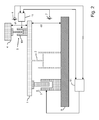
- FIG. 1 shows an active vibration system according to the state of the art.
- the platform 1 that is supported by a platform bearing 2 can be moved by an actuator 3.
- the reference mass 4 is supported by a reference mass bearing 5, whereas a first sensor 6 provides a signal that is representative for the distance d1 between the platform 1 and the reference mass 4 and a second sensor 7 provides a signal that is representative for the distance d2 between the reference mass 4 and the floor 8.
- the controller 9 is provided with the output signal of the first sensor 6 and the output signal of the second sensor 7 and the controller itself provides the actuator 3 with an input signal to move the platform 1.
- the platform 1 is suitable for accommodating a load, for example a precision instrument.
- Figure 2 shows schematically an embodiment of the system according to the invention.
- the embodiment shown merely by way of non-limiting example in Fig. 2 comprises a platform 1, a bearing 2, an actuator 3, a reference mass 4, a reference mass bearing 5, a first sensor 6 and a second sensor 7.
- the system further comprises a first control unit 11 for controlling the actuator 3 and a second control unit 15 for controlling the reference mass bearing 5.
- the platform 1 that is supported by a platform bearing 2 can be moved by an actuator 3.
- the platform bearing 2 and the actuator 3 might be two separate components, the functions of these two elements can be combined into one element like a Lorentz actuator.
- the reference mass 4 is supported by a reference mass bearing 5 that is designed in such a way that there is no mechanical contact between the mass and the platform.
- the system according to the invention also comprises a first sensor 6 providing a signal that is representative for the absolute distance d1 between the platform 1 and the reference mass 4, and a second sensor 7 providing a signal that is representative of the distance d2 between the reference mass 4 and the floor 8.
- the second sensor does not necessarily have to meet specific demands. It might be a velocity sensor or an acceleration sensor measuring the relative distance or a sensor that measures the absolute distance.
- the floor can also be any other construction supporting the platform bearing and the actuator whether or not this construction is fixed to earth.
- the reference mass 4 is mounted in a support unit 10 bearing the reference mass 4 without any mechanical contact.
- the support unit 10 serves as reference mass bearing 5.
- the support unit 10 is placed or mounted on the platform 1. In another embodiment of the system according to the invention, the support unit 10 is fixed to the platform 1.
- the controller 11 is provided with the output signal of the first sensor 6 and the output signal of the second sensor 7 and the controller 11 itself provides the actuator 3 with an input signal to move the platform 1.
- Figure 3 shows a preferred embodiment of a Lorentz type of support unit 10, the reference mass 4 and the sensor 6 with one degree of freedom.
- the sensor may be an optical interferometer, a capacitor or any other sensing element that can measure the distance between the reference mass 4 and the platform 1 or the housing 11 of the support unit placed on the platform or mounted on it.
- the sensor should be contactless, to prevent coupling of vibrations to the reference mass 4.
- the support unit 10 comprises a coil 13 in which a permanent magnet 14 is situated.
- the permanent magnet 14 is fixed to the reference mass 4.
- a movement in one of the other degrees of freedom is prevented by an air bearing 12.
- the reference mass may also be supported without making mechanical contacts by other means, such as particular configurations with several magnets or by means of an electrostatic force.
- Figure 5 shows the level of vibration of the base, which is assumed to have a root-mean-square (RMS) value of 1 ⁇ m over a bandwidth of 10 Hz.
- the resulting level of the platform is also depicted in Figure 5 .
- F p a
- K p K p , o ( 1 + ⁇ p ⁇ z p - z b - z p , o 2 ⁇ K i ⁇ V p
- V p the voltage output of the controller
- K i the gain of the voltage to current amplifier to drive the current through the coil.
- K p,o is the nominal motor constant of the voice coil and ⁇ p a parameter that determines the stiffness variation of the voice coil and z p,o the zero-stiffness position.
- the position-dependent gain Kp,o (1 + ⁇ p ( z p - z b - z p,o ) 2 ) of the voice coil actuator can be approximated by a more complex structure, such as a higher order polynomial, a rational function, a neural network, a spline approximation or table lookup.
- the coefficients of the interpolating functions can be determined on the basis of measured data using standard algorithms, such as (nonlinear) least squares or root finding methods.
- the sensor system is mounted on top of the platform.
- a preferred controller setup is depicted in Figure 6 .
- These relative positions are the inputs of four linear dynamic controllers, that are described below, and also used in the compensation of the voice coils stiffness dependency of the relative positions.
- the dynamics of the whole system can be described by linear differential equations.
- the controllers could be designed using optimal H 2 , LQG, or H ⁇ optimal control.
- H 2 , LQG, or H ⁇ optimal control the disadvantage is that in fact we want to optimize the performance particularly in the band 0.1-10 Hz, whereas these optimization methods optimize over the whole frequency range.
- these methods are based on the availability of very accurate parametric models of the system.
- the present invention does not follow this approach but provides insight in the relation between the controllers and the achieved vibration suppression and compliance behaviour, which result in tuning rules to determine the controller parameters.
- C s,s determines the resonance frequency and damping of the sensor system relative to the platform and C p,p the resonance frequency and damping of the platform relative to the base.
- C s,s is designed such that some stiffness is added to prevent the reference mass from drifting.
- C p,p is designed to reduce the stiffness k p and the damping d p , and thus to lower the resonance frequency of the platform.
- C p , p - 288.8 ⁇ s + 7.759 ⁇ 10 4 1 ⁇ 10 6 ⁇ s 2 + 0.002 ⁇ s + 1 which introduces a negative stiffness and damping together with two poles at 1000 rad/s to obtain sufficient roll-off at high frequencies. In this way the resonance frequency of the base-platform connection is shifted from 6.4 Hz to 2.6 Hz.
- controller C p s the basic 'absolute' position feedback; derivation of performance depending on C p,s interpretation of servo controller; Fig. 7 : bode-plot for loop-shaping of C p,s .
- Figs. 9 and 10 show the performance obtained, while Fig. 11 illustrates sensitivity at low frequencies to disturbance forces on the platform as well as noise due to the 1/f characteristic of the amplifier used to control voice coil 3.
- a stiffer connection between the platform and the inertial reference mass will slightly suppress the amplifier noise, but does not suppress the sensitivity to disturbance forces. It is generally better to use voice coil 3 as an inertial shaker to actively suppress these disturbances. This can be achieved by controller C s,p which actuates voice coil 3 using measurements from the sensor 7.
- Fig. 12 illustrates the suppression achieved at low frequencies, but at the expense of the performance below 1 Hz.
- the present invention is based upon the insight that a further improvement of present active vibration isolation systems is possible without increasing the compliance when using an inertial reference mass placed on, or at least attached to, the platform in combination with a control system that comprises both a feedback from the displacement of the platform relative to the inertial reference mass and a feedback from the displacement of the platform relative to the source of the vibration.
- the present invention not only relates to protecting the isolated equipment from vibrations originating from its environment but also to protecting the environment from the vibrations originating from the equipment that is isolated.
Landscapes
- Engineering & Computer Science (AREA)
- General Engineering & Computer Science (AREA)
- Physics & Mathematics (AREA)
- Health & Medical Sciences (AREA)
- Acoustics & Sound (AREA)
- Aviation & Aerospace Engineering (AREA)
- Mechanical Engineering (AREA)
- Life Sciences & Earth Sciences (AREA)
- Electromagnetism (AREA)
- Atmospheric Sciences (AREA)
- Toxicology (AREA)
- Environmental & Geological Engineering (AREA)
- Epidemiology (AREA)
- Public Health (AREA)
- General Physics & Mathematics (AREA)
- Vibration Prevention Devices (AREA)
Priority Applications (5)
| Application Number | Priority Date | Filing Date | Title |
|---|---|---|---|
| EP07124174A EP2075484A1 (fr) | 2007-12-31 | 2007-12-31 | Système d'isolation à vibration active ayant une masse de référence d'inertie |
| PCT/NL2008/050862 WO2009084963A1 (fr) | 2007-12-31 | 2008-12-31 | Système actif d'isolation des vibrations comprenant une masse de référence inertielle |
| EP08867058.3A EP2235394B1 (fr) | 2007-12-31 | 2008-12-31 | Système d'isolation à vibration active ayant une masse de référence d'inertie |
| TW097151914A TW200951321A (en) | 2007-12-31 | 2008-12-31 | An active vibration isolation system having an inertial reference mass |
| US12/826,411 US20110127400A1 (en) | 2007-12-31 | 2010-06-29 | Active vibration isolation system having an inertial reference mass |
Applications Claiming Priority (1)
| Application Number | Priority Date | Filing Date | Title |
|---|---|---|---|
| EP07124174A EP2075484A1 (fr) | 2007-12-31 | 2007-12-31 | Système d'isolation à vibration active ayant une masse de référence d'inertie |
Publications (1)
| Publication Number | Publication Date |
|---|---|
| EP2075484A1 true EP2075484A1 (fr) | 2009-07-01 |
Family
ID=39535212
Family Applications (2)
| Application Number | Title | Priority Date | Filing Date |
|---|---|---|---|
| EP07124174A Withdrawn EP2075484A1 (fr) | 2007-12-31 | 2007-12-31 | Système d'isolation à vibration active ayant une masse de référence d'inertie |
| EP08867058.3A Not-in-force EP2235394B1 (fr) | 2007-12-31 | 2008-12-31 | Système d'isolation à vibration active ayant une masse de référence d'inertie |
Family Applications After (1)
| Application Number | Title | Priority Date | Filing Date |
|---|---|---|---|
| EP08867058.3A Not-in-force EP2235394B1 (fr) | 2007-12-31 | 2008-12-31 | Système d'isolation à vibration active ayant une masse de référence d'inertie |
Country Status (4)
| Country | Link |
|---|---|
| US (1) | US20110127400A1 (fr) |
| EP (2) | EP2075484A1 (fr) |
| TW (1) | TW200951321A (fr) |
| WO (1) | WO2009084963A1 (fr) |
Cited By (3)
| Publication number | Priority date | Publication date | Assignee | Title |
|---|---|---|---|---|
| WO2015127863A1 (fr) * | 2014-02-28 | 2015-09-03 | 上海微电子装备有限公司 | Plateau pour pièce à travailler de machine de lithographie et son procédé d'initialisation de position verticale |
| EP2944966A1 (fr) | 2014-05-15 | 2015-11-18 | Etel S. A.. | Capteur de vibrations |
| EP3093965A1 (fr) | 2015-05-12 | 2016-11-16 | Etel S. A.. | Moteur linéaire supercarré |
Families Citing this family (13)
| Publication number | Priority date | Publication date | Assignee | Title |
|---|---|---|---|---|
| EP2261530A1 (fr) * | 2009-06-12 | 2010-12-15 | Nederlandse Organisatie voor toegepast -natuurwetenschappelijk onderzoek TNO | Système d'amortissement et d'isolation de vibration active |
| JP5882798B2 (ja) * | 2012-03-14 | 2016-03-09 | キヤノン株式会社 | 振動抑制装置および振動抑制方法 |
| JP6218459B2 (ja) * | 2013-07-02 | 2017-10-25 | キヤノン株式会社 | 除振装置、除振方法、リソグラフィ装置及びデバイスの製造方法 |
| JP6278676B2 (ja) * | 2013-11-29 | 2018-02-14 | キヤノン株式会社 | 振動低減装置、リソグラフィ装置、および物品の製造方法 |
| JP6302305B2 (ja) * | 2014-03-18 | 2018-03-28 | キヤノン株式会社 | 振動低減装置、リソグラフィ装置、および物品の製造方法 |
| EP3208036A1 (fr) * | 2016-02-16 | 2017-08-23 | Siemens Aktiengesellschaft | Amortissement d'oscillations d'une machine-outil |
| US10840059B2 (en) * | 2016-07-28 | 2020-11-17 | Hitachi High-Tech Corporation | Charged particle radiation device |
| JP7009296B2 (ja) * | 2018-04-23 | 2022-01-25 | 倉敷化工株式会社 | アクティブ除振システム |
| EP3845772B1 (fr) * | 2018-08-31 | 2022-10-12 | Panasonic Intellectual Property Management Co., Ltd. | Dispositif de commande des vibrations |
| JP7308156B2 (ja) | 2020-01-09 | 2023-07-13 | 倉敷化工株式会社 | アクティブ防振装置 |
| CN113394941B (zh) * | 2021-06-16 | 2022-11-11 | 西北工业大学 | 一种电磁-压电混合式双效准零刚度振动俘能装置 |
| CN114279666B (zh) * | 2021-12-24 | 2024-03-05 | 杭州亿恒科技有限公司 | 串联式主动振动控制实验装置 |
| NL1044323B1 (en) * | 2022-05-09 | 2023-11-16 | Jpe | Active controlled modular multi-DoF vibration isolator for cryogenic environment |
Citations (5)
| Publication number | Priority date | Publication date | Assignee | Title |
|---|---|---|---|---|
| DE29612349U1 (de) * | 1996-07-16 | 1997-11-20 | Heiland Peter | Aktives Schwingungsdämpfungs- und Schwingungsisolationssystem |
| US20040060792A1 (en) * | 2002-09-27 | 2004-04-01 | Koninklijke Philips Electronics N.V. | System and method for active vibration isolation and active vibration cancellation |
| US20050018160A1 (en) * | 2003-06-13 | 2005-01-27 | Asml Netherlands B.V. | Supporting device, lithographic apparatus, and device manufacturing method employing a supporting device, and a position control system arranged for use in a supporting device |
| WO2005024266A1 (fr) | 2003-09-05 | 2005-03-17 | Koninklijke Philips Electronics N.V. | Agencement actionneur d'isolation active de vibrations a masse inertielle de reference |
| WO2005073592A1 (fr) * | 2004-01-26 | 2005-08-11 | Koninklijke Philips Electronics N.V. | Ensemble actionneur destine a une isolation active aux vibrations a l'aide d'une charge utile utilisee comme masse de reference a inertie |
Family Cites Families (16)
| Publication number | Priority date | Publication date | Assignee | Title |
|---|---|---|---|---|
| JPH086493B2 (ja) * | 1991-05-29 | 1996-01-24 | 鹿島建設株式会社 | 構造物の振動制御装置 |
| US5660255A (en) * | 1994-04-04 | 1997-08-26 | Applied Power, Inc. | Stiff actuator active vibration isolation system |
| EP1015787B8 (fr) * | 1997-09-26 | 2006-02-01 | Vistek Inc. | Dispositif d'isolation contre les microvibrations |
| NL1007127C2 (nl) * | 1997-09-26 | 1999-03-29 | Univ Delft Tech | Draagsysteem. |
| JPH11230246A (ja) * | 1998-02-18 | 1999-08-27 | Tokkyo Kiki Kk | アクティブ除振装置 |
| US6059274A (en) * | 1998-05-04 | 2000-05-09 | Gte Internetworking Incorporated | Vibration reduction system using impedance regulated active mounts and method for reducing vibration |
| FR2784350B1 (fr) * | 1998-10-12 | 2000-12-08 | Eurocopter France | Dispositif pour reduire des vibrations engendrees sur la structure d'un aeronef a voilure tournante |
| US6378672B1 (en) * | 1998-10-13 | 2002-04-30 | Canon Kabushiki Kaisha | Active vibration isolation device and its control method |
| JP2001271868A (ja) * | 2000-03-24 | 2001-10-05 | Canon Inc | 除振装置 |
| JP4845323B2 (ja) * | 2000-06-30 | 2011-12-28 | ビステック, インコーポレイテッド | 機械的信号フィルタ |
| FR2825768B1 (fr) * | 2001-06-06 | 2004-03-12 | Vibrachoc Sa | Dispositif d'amortissement de vibrations |
| GB2406369B (en) * | 2003-09-24 | 2007-05-09 | Ultra Electronics Ltd | Active vibration absorber and method |
| US7726452B2 (en) * | 2005-06-02 | 2010-06-01 | Technical Manufacturing Corporation | Systems and methods for active vibration damping |
| JP2008256155A (ja) * | 2007-04-06 | 2008-10-23 | Canon Inc | 除振装置、演算装置、露光装置及びデバイス製造方法 |
| EP2119938A1 (fr) * | 2008-05-15 | 2009-11-18 | Nederlandse Organisatie voor toegepast-natuurwetenschappelijk Onderzoek TNO | Capteur de vibrations et système destiné à isoler les vibrations |
| US20100030384A1 (en) * | 2008-07-29 | 2010-02-04 | Technical Manufacturing Corporation | Vibration Isolation System With Design For Offloading Payload Forces Acting on Actuator |
-
2007
- 2007-12-31 EP EP07124174A patent/EP2075484A1/fr not_active Withdrawn
-
2008
- 2008-12-31 WO PCT/NL2008/050862 patent/WO2009084963A1/fr active Application Filing
- 2008-12-31 EP EP08867058.3A patent/EP2235394B1/fr not_active Not-in-force
- 2008-12-31 TW TW097151914A patent/TW200951321A/zh unknown
-
2010
- 2010-06-29 US US12/826,411 patent/US20110127400A1/en not_active Abandoned
Patent Citations (6)
| Publication number | Priority date | Publication date | Assignee | Title |
|---|---|---|---|---|
| DE29612349U1 (de) * | 1996-07-16 | 1997-11-20 | Heiland Peter | Aktives Schwingungsdämpfungs- und Schwingungsisolationssystem |
| US20040060792A1 (en) * | 2002-09-27 | 2004-04-01 | Koninklijke Philips Electronics N.V. | System and method for active vibration isolation and active vibration cancellation |
| WO2004029475A1 (fr) | 2002-09-27 | 2004-04-08 | Koninklijke Philips Electronics N.V. | Systeme et procede permettant d'isoler ou de supprimer une vibration active |
| US20050018160A1 (en) * | 2003-06-13 | 2005-01-27 | Asml Netherlands B.V. | Supporting device, lithographic apparatus, and device manufacturing method employing a supporting device, and a position control system arranged for use in a supporting device |
| WO2005024266A1 (fr) | 2003-09-05 | 2005-03-17 | Koninklijke Philips Electronics N.V. | Agencement actionneur d'isolation active de vibrations a masse inertielle de reference |
| WO2005073592A1 (fr) * | 2004-01-26 | 2005-08-11 | Koninklijke Philips Electronics N.V. | Ensemble actionneur destine a une isolation active aux vibrations a l'aide d'une charge utile utilisee comme masse de reference a inertie |
Non-Patent Citations (3)
| Title |
|---|
| NELSON P G: "AN ACTIVE VIBRATION ISOLATION SYSTEM FOR INERTIAL REFERENCE AND PRECISION MEASUREMENT", REVIEW OF SCIENTIFIC INSTRUMENTS, AIP, MELVILLE, NY, US, vol. 62, no. 9, 1 September 1991 (1991-09-01), pages 2069 - 2075, XP000262841, ISSN: 0034-6748 * |
| P.G. NELSON: "An active vibration isolation system for inertial reference and precision measurement", REV. SCI. INSTRUM., vol. 62, no. 9, September 1991 (1991-09-01), pages 2069 - 2075 |
| P.R. SAULSON: "Vibration isolation for broadband gravitational wave antennas", REV. SCI. INSTRUM., vol. 55, no. 8, August 1984 (1984-08-01), pages 1315 - 1320 |
Cited By (8)
| Publication number | Priority date | Publication date | Assignee | Title |
|---|---|---|---|---|
| WO2015127863A1 (fr) * | 2014-02-28 | 2015-09-03 | 上海微电子装备有限公司 | Plateau pour pièce à travailler de machine de lithographie et son procédé d'initialisation de position verticale |
| US9760022B2 (en) | 2014-02-28 | 2017-09-12 | Shanghai Micro Electronics Equipment (Group) Co., Ltd. | Lithography machine workpiece table and vertical position initialization method thereof |
| EP2944966A1 (fr) | 2014-05-15 | 2015-11-18 | Etel S. A.. | Capteur de vibrations |
| KR20150131955A (ko) * | 2014-05-15 | 2015-11-25 | 에텔 쏘시에떼 아노님 | 진동 센서 |
| US9810710B2 (en) | 2014-05-15 | 2017-11-07 | Etel S.A. | Vibration sensor |
| KR102292403B1 (ko) * | 2014-05-15 | 2021-08-24 | 에텔 쏘시에떼 아노님 | 진동 센서 |
| EP3093965A1 (fr) | 2015-05-12 | 2016-11-16 | Etel S. A.. | Moteur linéaire supercarré |
| US10581309B2 (en) | 2015-05-12 | 2020-03-03 | Etel S.A. | Short-stroke linear motor |
Also Published As
| Publication number | Publication date |
|---|---|
| EP2235394B1 (fr) | 2014-12-03 |
| TW200951321A (en) | 2009-12-16 |
| US20110127400A1 (en) | 2011-06-02 |
| WO2009084963A1 (fr) | 2009-07-09 |
| EP2235394A1 (fr) | 2010-10-06 |
Similar Documents
| Publication | Publication Date | Title |
|---|---|---|
| EP2235394B1 (fr) | Système d'isolation à vibration active ayant une masse de référence d'inertie | |
| Chen et al. | Design and control for an electromagnetically driven X–Y–θ stage | |
| US6170622B1 (en) | Anti-vibration apparatus and anti-vibration method thereof | |
| KR101719380B1 (ko) | 능동형 진동 차단 및 감쇠 시스템 | |
| US8610332B2 (en) | Positioning system and method | |
| JP4209121B2 (ja) | デュアル分離されたシステムを有するリソグラフィーツールおよびそれを構成する方法 | |
| US6196514B1 (en) | Large airborne stabilization/vibration isolation system | |
| JP5699269B2 (ja) | 加速度計及びトランスデューサ | |
| US6473159B1 (en) | Anti-vibration system in exposure apparatus | |
| US6563128B2 (en) | Base stabilization system | |
| US8352086B2 (en) | Combined motion sensor for use in feedback control systems for vibration isolation | |
| EP2286110B1 (fr) | Capteur de vibrations et système destiné à isoler les vibrations | |
| WO2007054860A2 (fr) | Systeme et procede d'isolation contre une vibration | |
| Xie et al. | Ultra-low frequency active vibration isolation in high precision equipment with electromagnetic suspension: Analysis and experiment | |
| Cigarini et al. | Compensation of hysteresis in hybrid reluctance actuator for high-precision motion | |
| JP3286186B2 (ja) | 微動位置決め制御装置 | |
| US7942251B2 (en) | System limiting the transmission of mechanical vibrations by frequency filtering | |
| CN100465473C (zh) | 包括惯性基准质量的用于主动隔振的致动器装置 | |
| Bertolini et al. | Readout system and predicted performance of a low-noise low-frequency horizontal accelerometer | |
| JPH0915868A (ja) | 能動的除振装置 | |
| Takahashi et al. | Vibration Isolator using Hybrid Reluctance Actuator toward Quasi-zero Stiffness | |
| JP5912338B2 (ja) | 力測定装置 | |
| Awtar et al. | Physical and Control System Design Challenges in Large Range Nanopositioning | |
| Friedl et al. | Design and Control of a Table-top Vibration Isolation System With Zero-Power Gravity Compensation | |
| JPH1144337A (ja) | 空気ばね式能動的除振装置 |
Legal Events
| Date | Code | Title | Description |
|---|---|---|---|
| PUAI | Public reference made under article 153(3) epc to a published international application that has entered the european phase |
Free format text: ORIGINAL CODE: 0009012 |
|
| AK | Designated contracting states |
Kind code of ref document: A1 Designated state(s): AT BE BG CH CY CZ DE DK EE ES FI FR GB GR HU IE IS IT LI LT LU LV MC MT NL PL PT RO SE SI SK TR |
|
| AX | Request for extension of the european patent |
Extension state: AL BA HR MK |
|
| AKX | Designation fees paid | ||
| REG | Reference to a national code |
Ref country code: DE Ref legal event code: 8566 |
|
| STAA | Information on the status of an ep patent application or granted ep patent |
Free format text: STATUS: THE APPLICATION IS DEEMED TO BE WITHDRAWN |
|
| 18D | Application deemed to be withdrawn |
Effective date: 20100105 |