EP2073564A1 - A method, a device and a system for transmitting data - Google Patents
A method, a device and a system for transmitting data Download PDFInfo
- Publication number
- EP2073564A1 EP2073564A1 EP08715400A EP08715400A EP2073564A1 EP 2073564 A1 EP2073564 A1 EP 2073564A1 EP 08715400 A EP08715400 A EP 08715400A EP 08715400 A EP08715400 A EP 08715400A EP 2073564 A1 EP2073564 A1 EP 2073564A1
- Authority
- EP
- European Patent Office
- Prior art keywords
- data rate
- parameter
- idle
- adjusting
- transmission
- Prior art date
- Legal status (The legal status is an assumption and is not a legal conclusion. Google has not performed a legal analysis and makes no representation as to the accuracy of the status listed.)
- Withdrawn
Links
Images


Classifications
-
- H—ELECTRICITY
- H04—ELECTRIC COMMUNICATION TECHNIQUE
- H04M—TELEPHONIC COMMUNICATION
- H04M11/00—Telephonic communication systems specially adapted for combination with other electrical systems
- H04M11/06—Simultaneous speech and data transmission, e.g. telegraphic transmission over the same conductors
- H04M11/062—Simultaneous speech and data transmission, e.g. telegraphic transmission over the same conductors using different frequency bands for speech and other data
-
- H—ELECTRICITY
- H04—ELECTRIC COMMUNICATION TECHNIQUE
- H04L—TRANSMISSION OF DIGITAL INFORMATION, e.g. TELEGRAPHIC COMMUNICATION
- H04L12/00—Data switching networks
- H04L12/28—Data switching networks characterised by path configuration, e.g. LAN [Local Area Networks] or WAN [Wide Area Networks]
- H04L12/2854—Wide area networks, e.g. public data networks
- H04L12/2856—Access arrangements, e.g. Internet access
- H04L12/2869—Operational details of access network equipments
- H04L12/2898—Subscriber equipments
-
- H—ELECTRICITY
- H04—ELECTRIC COMMUNICATION TECHNIQUE
- H04Q—SELECTING
- H04Q11/00—Selecting arrangements for multiplex systems
- H04Q11/04—Selecting arrangements for multiplex systems for time-division multiplexing
-
- H—ELECTRICITY
- H04—ELECTRIC COMMUNICATION TECHNIQUE
- H04Q—SELECTING
- H04Q2213/00—Indexing scheme relating to selecting arrangements in general and for multiplex systems
- H04Q2213/13039—Asymmetrical two-way transmission, e.g. ADSL, HDSL
-
- H—ELECTRICITY
- H04—ELECTRIC COMMUNICATION TECHNIQUE
- H04Q—SELECTING
- H04Q2213/00—Indexing scheme relating to selecting arrangements in general and for multiplex systems
- H04Q2213/13166—Fault prevention
-
- H—ELECTRICITY
- H04—ELECTRIC COMMUNICATION TECHNIQUE
- H04Q—SELECTING
- H04Q2213/00—Indexing scheme relating to selecting arrangements in general and for multiplex systems
- H04Q2213/13213—Counting, timing circuits
-
- H—ELECTRICITY
- H04—ELECTRIC COMMUNICATION TECHNIQUE
- H04Q—SELECTING
- H04Q2213/00—Indexing scheme relating to selecting arrangements in general and for multiplex systems
- H04Q2213/13216—Code signals, frame structure
-
- H—ELECTRICITY
- H04—ELECTRIC COMMUNICATION TECHNIQUE
- H04Q—SELECTING
- H04Q2213/00—Indexing scheme relating to selecting arrangements in general and for multiplex systems
- H04Q2213/13332—Broadband, CATV, dynamic bandwidth allocation
-
- H—ELECTRICITY
- H04—ELECTRIC COMMUNICATION TECHNIQUE
- H04Q—SELECTING
- H04Q2213/00—Indexing scheme relating to selecting arrangements in general and for multiplex systems
- H04Q2213/13363—Pulse stuffing, bit stuffing
-
- Y—GENERAL TAGGING OF NEW TECHNOLOGICAL DEVELOPMENTS; GENERAL TAGGING OF CROSS-SECTIONAL TECHNOLOGIES SPANNING OVER SEVERAL SECTIONS OF THE IPC; TECHNICAL SUBJECTS COVERED BY FORMER USPC CROSS-REFERENCE ART COLLECTIONS [XRACs] AND DIGESTS
- Y02—TECHNOLOGIES OR APPLICATIONS FOR MITIGATION OR ADAPTATION AGAINST CLIMATE CHANGE
- Y02D—CLIMATE CHANGE MITIGATION TECHNOLOGIES IN INFORMATION AND COMMUNICATION TECHNOLOGIES [ICT], I.E. INFORMATION AND COMMUNICATION TECHNOLOGIES AIMING AT THE REDUCTION OF THEIR OWN ENERGY USE
- Y02D30/00—Reducing energy consumption in communication networks
- Y02D30/50—Reducing energy consumption in communication networks in wire-line communication networks, e.g. low power modes or reduced link rate
Definitions
- the present invention relates to electronic communication field, and more specifically, to a method, apparatus and system for data transmission.
- Digital Subscriber Line (DSL) technology is a high-speed transmission technology which employs telephone twisted pair wires (also called Unshielded Twist Pair, UTP) to transmit data.
- the DSL technology includes Asymmetric Digital Subscriber Line (ADSL) technology, Very high speed digital Subscriber Line (VDSL) technology, Digital Subscriber Line based on Integrated Services Digital Network (IDSL) technology, Symmetrical High bite Digital Subscriber Line (SHDSL) technology, etc.
- ADSL Asymmetric Digital Subscriber Line
- VDSL Very high speed digital Subscriber Line
- IDSL Digital Subscriber Line based on Integrated Services Digital Network
- SHDSL Symmetrical High bite Digital Subscriber Line
- a DSL Access Multiplexer may provide multiple DSL accesses so as to construct a network system based on xDSL technology.
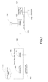
- a framework of the network system is shown in Figure 1 , which includes a user end xDSL transceiver 120, a central office xDSL transceiver 150, a Public Switched Telephone Network (PSTN) 160, and a Network Management System (NMS) 170.
- the xDSL transceiver 120 includes a user end transceiving unit 121 and a splitter/integrator 122.
- the xDSL transceiver 150 includes a central office tranceiving unit 152 and a splitter/integrator 151.
- a data transmission process is illustrated in a diagram in Figure 1 .
- the user end transceiving unit 121 receives a DSL signal from computer 110, amplifies the received signal, and transmits the processed DSL signal to the splitter/integrator 122.
- the splitter/integrator 122 integrates the DSL signal from the user end transceiving unit 121 and a Plain Old Telephone Service (POTS) signal from a telephone terminal 130.
- POTS Plain Old Telephone Service
- the integrated signals are transmitted via multiple UTP 140 and are received by the splitter/integrator 151 in the central office xDSL tranceiver 150.
- the splitter/integrator 151 separates the received signals.
- the POTS signal in the received signals is transmitted to the Public Switched Telephone Network (PSTN) 160.
- PSTN Public Switched Telephone Network
- the DSL signal in the received signals is transmitted to the transceiving unit 152 of the the xDSL transceiver 150. Then, the transceiving unit 152 amplifies the received signal and transmits the amplified signal to the Network Management System (NMS) 170. In downstream direction, signals are transmitted in a reverse order.
- NMS Network Management System
- VDSL2 the second generation VDSL technology
- Triple play services requires a lower bit error ratio (BER) than does a traditional data service (e.g., Internet data service).
- BER bit error ratio
- the DSL technology employs a noise margin technique and a trellis coding technique to eliminate the impact of random noise, and jointly employs a Forward Error Correction (FEC) technique and an interleave technique to eliminate the impact of pulse noises so as to reduce bit error ratio.
- FEC Forward Error Correction
- an interleave technique to eliminate the impact of pulse noises so as to reduce bit error ratio.
- SDTV Standard TV
- HDTV High Definition TV
- the DSL technology utilizes a huge number of idle frames to fill in the remaining bandwidth so as to solve the problem that the user utilizes only a portion of bandwidth.
- the speed of the DSL system does not decrease.
- these idle frames make no contribution to reducing the BER of user data, the BER of user data is not reduced.
- the manner of utilizing the idle frames to fill in the remaining bandwidth is not conducive to reducing the BER of user data.
- the waste of bandwidth becomes a prominent phenomenon.
- L2 mode (save mode or sleep mode) relating to DSL technology is currently used. That is, when the user data rate decreases to a certain degree, L2 mode is enabled. In L2 mode, by lowering transmit power, the DSL line rate is reduced. As such, the energy may be saved, the crosstalk on the neighboring lines may be reduced, and the waste of bandwidth is mitigated. However, this has no impact on the BER.
- L2 mode is again switched to L0 mode (normal mode). In order to switch L2 mode to normal mode L0 quickly, the system saves operating parameters in original L0 mode. The L0 mode after switching may use the previous parameters for operation.
- the DSL technology utilizes unshielded twisted pair (UTP)
- UTP unshielded twisted pair
- the crosstalk between neighboring twisted pair wires is serious.
- the DSL service may suffer from severe crosstalk.
- SNR signal-to-noise ratio
- the existence of the huge number of bit errors may cause the DSL service to be dropped off line, which means a failure in switching from L2 mode to L0 mode. Because such switching failures occur frequently, L2 mode does not come into an extensive use even though L2 mode is an optional function in ADSL standard.
- the current VDSL2 standard does not include L2 mode.
- a method, apparatus and system for data transmission are provided according to embodiments of the present invention.
- the system BER can be reduced and the idle data rate can be decreased when there is a large amount of idle data rate under the total data rate in transmission.
- the user data can be transmitted as much as possible when there are few idle data rate under the total data rate in transmission.
- Embodiments of the present invention can be implemented according to the below technical solutions.
- a method for data transmission includes determining an idle data rate under a total data rate during data transmission; determining a corresponding parameter adjusting policy according to the idle data rate and a preset threshold; and adjusting an associated parameter during data transmission according to the parameter adjusting policy and transmitting an instruction carrying the parameter adjusting policy to a peer entity so as to instruct the peer entity to adjust associated parameter during data transmission accordingly.
- An apparatus for data transmission includes: a monitoring unit adapted to determine an idle data rate under a total data rate during data transmission; a decision-making unit adapted to determine a corresponding parameter adjusting policy according to the idle data rate monitored by the monitoring unit and a preset threshold; an adjusting unit adapted to adjust an associated parameter during data transmission according to the parameter adjusting policy determined by the decision-making unit; and a parameter transmitting unit adapted to transmit an instruction carrying the parameter adjusting policy to a far end entity, so as to instruct the far end entity to adjust an associated parameter during data transmission.
- a system for data transmission is provided according to one embodiment of the present invention.
- the system includes a first communication apparatus and a second communication apparatus.
- the first communication apparatus includes: a monitoring unit adapted to determine an idle data rate under a total data rate during data transmission; a decision-making unit adapted to determine a corresponding parameter adjusting policy according to the idle data rate determined by the monitoring unit and a preset threshold; an adjusting unit adapted to adjust an associated parameter during data transmission according to the parameter adjusting policy determined by the decision-making unit; and a parameter transmitting unit adapted to transmit an instruction carrying the parameter adjusting policy to the second communication apparatus;
- the second communication apparatus includes: a parameter receiving unit, adapted to receive the instruction carrying the parameter adjusting policy from the first communication apparatus; and a third adjusting unit, adapted to adjust an associated parameter during data transmission according to the parameter adjusting policy carried in the received instruction.
- the present invention provides a method, apparatus, and system for data transmission to adjust data transmission process according to a determined parameter adjusting policy. Accordingly, the system BER may be declined effectively, the system bandwidth may be saved and the system service quality can be improved.
- Figure 1 is a diagram of network system based on xDSL technology
- FIG. 2 is a flowchart according to one embodiment of the present invention.
- FIG. 3 is a system diagram according to one embodiment of the present invention.
- the technical solution of the embodiments of the present invention includes determining an idle data rate under the total data rate during data transmission; determining a corresponding parameter adjusting policy according to the idle data rate and a preset threshold; adjusting an associated parameter during data transmission according to the parameter adjusting policy and transmitting an instruction carrying the parameter adjusting policy to a far end entity so as to instruct the far end entity to adjust the associated parameter during data transmission accordingly.
- the far end entity may be a data transmitting end or a data receiving end.
- the total data rate may include a user data rate.
- the total data rate may further include at least one of idle data rate and redundancy overhead.
- the preset threshold may include a high threshold and a low threshold which are preset according to system BER and other parameter requirements.
- the idle data rate can be determined by monitoring user data rate and/or idle data rate, or monitoring the ratio of idle data rate to user data rate.
- the determined parameter adjusting policy may include increasing the redundancy overhead in the total data rate with the total data rate unchanged. Adjusting the parameter information may reduce the BER, and increase impulse noise protection (INP). The determined parameter adjusting policy may also be such a policy as to decrease the total data rate in transmission with the user data rate unchanged. Adjusting the parameter information may reduce the BER.
- the determined parameter adjusting policy is to decrease the redundancy overhead in the total data rate with total data rate unchanged, or, to increase total data rate in transmission.
- the redundancy overhead can be increased or reduced by adjusting some parameters of the system such as adjusting the redundancy overhead parameter of FEC.
- the total data rate for system transmission can be increased or reduced by adjusting a bitloading table of at least one subcarrier.
- Figure 2 is a flowchart of a method according to one embodiment of the present invention. The method includes the following steps.
- Step 1 ratio of user data rate to idle data rate is monitored. If the ratio increases, step 2 is performed. If the ratio decreases, step 5 is performed.
- Step 2 whether the ratio reaches a preset rate threshold 1 (i.e., the low threshold of idle data rate) is determined. If the ratio does not reach the preset rate threshold, step 1 is performed; otherwise, step 3 is performed.
- a preset rate threshold 1 i.e., the low threshold of idle data rate
- Step 3 time-counting is started and whether the duration time for maintaining at the rate threshold 1 reaches a preset time threshold 1 is determined. If the duration time for maintaining at the rate threshold 1 does not reach the preset time threshold 1, step 2 is performed; otherwise, step 4 is performed.
- Step 4 the system parameter is adjusted and idle data rate is decreased so that the BER is reduced. The process is over.
- Step 5 whether the ratio reaches a preset rate threshold 2 (i.e., the high threshold of idle data rate) is determined. If the ratio does not reach the preset rate threshold 2, step is performed 1; otherwise, step 6 is performed.
- a preset rate threshold 2 i.e., the high threshold of idle data rate
- Step 6 time-counting is started and whether the duration time for maintaining at the rate threshold 2 reaches a preset time threshold 2 is determined. If the duration time for maintaining at the rate threshold 2 does not reach the preset time threshold 2, step 5 is performed; otherwise, step 7 is performed.
- Step 7 the system parameter is adjusted and the total data rate or reduce the number of redundant bits is increased in an allowable BER range. The process is over.
- the system may transmit the user data as much as possible when the user data rate is increased.
- the system may provide users with a better service quality than does the current system when the user data rate is decreased.
- the user may also be provided with an option between the rate and the service quality. And the way of making the option is very simple. Users may simply close some services so as to improve the quality of the rest of the services. For instance, currently, three HDTVs are running simultaneously. If the service quality is worse (which might be caused by weather change, environment change, etc), one might need to close only one of the HDTV. The service quality of the other two HDTVs is improved considerably. If a higher service quality is desired, one more HDTV may be closed. Consequently, the service quality of the rest HDTV may be further improved.
- step 4 and step 7 methods of adjusting the redundancy overhead parameter of FEC or adjusting the bitloading table of at least one subcarrier may be adopted in one embodiment of the present invention.
- the specific implementations with these two methods will be detailed below respectively.
- step 4 and step 7 in the embodiments of the present invention are described in detail taking Reed Solomon (RS) coding parameter as an example.
- RS Reed Solomon
- Step 4 may include setting RS coding parameters according to the idle data rate and the RS (a type of coding) parameter supported by the system so as to increase the number of redundant bits in the total data rate.
- step 4 may includes setting at least one parameter in the RS coding parameters, for example, N FEC (denoting the code length of RS ) and R (denoting the number of redundant bytes of RS).
- setting the N FEC and R can be done in the following way.
- the value of R / N FEC should be larger than value of R / N FEC prior to being set.
- the value of RlN FEC needs to ensure INP larger than INP min (i.e., the minimum INP set by the user) and to minimize the ratio of idle data rate to the user data rate.
- INP is calculated according to the following formula when the other parameters remain unchanged and only when the number of redundant bytes R of RS has been changed.
- the redundancy overhead increases and the value of R / N FEC increases, and thus INP increases.
- the redundancy overhead decreases and the value of R / N FEC decreases, and thus INP decreases.
- the increase in redundancy overhead may also restrain general noises, such as crosstalk.
- Step 7 may include the following.
- the user data rate increases e.g., the number of HDTVs used has been changed from one to three
- the idle data rate is almost zero.
- the majority of the total data rate of the system is occupied by the user data rate.
- the RS coding parameters N FEC and R are adjusted to meet the requirement of INP min , i.e., reduce the ratio of R / N FEC.
- the user data rate can be increased while meeting the requirement of minimum BER, thereby meeting the requirement of the user with a large user data traffic.
- the transmitting end may transmit the system parameters which need to be adjusted and the value of the adjusted system parameter by a previous frame carrying RS coding parameter of a next frame (e.g., the modified N FEC and R).
- a previous frame carrying RS coding parameter of a next frame e.g., the modified N FEC and R.
- the transmitting end utilizes two bytes having fixed location in a previous Over Head (OH) frame to transmit two parameters N FEC and R of the RS coding parameters of a next OH frame.
- the receiving end receives the previous OH frame, decodes the OH frame to obtain parameters N FEC and R which will be used for decoding the next OH frame.
- the method is easy for implementation.
- the 4 th byte of an OH frame may be used to transmit R and N.
- a fast method is that each OH frame may utilize different R and N.
- the previous OH frame transmits the R and N of a next OH frame.
- An alternative method is to set an OH superframe to modify R and N.
- the transmitting end may repeat R and N several times with the OH frame and transmits to the receiving end.
- the receiving end may return the R and N to the transmitting end using an OH frame so as to acknowledge a correct reception.
- OH frames with odd numbers may indicate a forward transmission
- OH frames with even numbers may indicate a return transmission.
- the idle data rate can be utilized by adjusting the ratio of redundant RS bytes to RS bytes so as to improve the INP and reduce the BER.
- the adjusting speed is fast, and the adjustment has a wide range.
- the service quality of the system can be improved, e.g., BER can be declined, and INP can be improved, etc.
- step 4 and step 7 of the embodiments of the present invention are detailed below.
- Step 4 may include calculating a bitloading table according to the idle data rate.
- the bitloading table may enable the total data rate in transmission to decrease. For instance, a subcarrier used to load 12000 bits. Now, a subcarrier is set to load only 8000 bits. As such, the SNR margin of this subcarrier is increased such that it may counter heavier non-pulse noise. All the subcarriers may be processed with the same method and a new bitloading table can be obtained.
- the new bit loading table may be transmitted to the receiving end via an Embedded Operations Channel (EOC). After the receiving end agrees to perform switching, the transmitting end transmits a special synchronization symbol which specifies that both ends may switch an n th symbol after the synchronization symbol to the new bitloading table.
- EOC Embedded Operations Channel
- Step 7 may include the following.
- the number of HDTVs used has been changed from one to three. At this point, the idle data rate is almost zero. The majority of the total data rate of the system is occupied by the user data rate.
- the bitloading table can be switched to the original bitloading table according to the same step as step 4.
- the embodiment has a wide range of adjustment.
- the service quality of the system may also be improved, e.g., the BER may be declined.
- FIG. 3 is a flowchart of system implementation according to one embodiment of the present invention.
- the system includes a first communication apparatus and a second communication apparatus.
- the first communication apparatus includes a monitoring unit, a decision-making unit, an adjusting unit and a parameter transmitting unit.
- the second communication apparatus includes a parameter receiving unit and a third adjusting unit.
- the monitoring unit is adapted to determine an idle data rate under the total data rate during data transmission.
- the decision-making unit is adapted to determine a corresponding parameter adjusting policy according to the idle data rate determined by the monitoring unit and a preset threshold.
- the parameters relating to the parameter adjusting policy may include a system redundancy overhead parameter, or the number of bits loaded on at least one subcarrier.
- the redundancy overhead may be RS coding parameters. For instance, N FEC and R.
- the adjusting unit is adapted to adjust an associated parameter during data transmission according to the parameter adjusting policy determined by the decision-making unit.
- the adjusting unit includes: a first adjusting unit, adapted to decrease the idle data rate in the case where the idle data rate is higher than a preset high threshold; and/or a second adjusting unit, adapted to reduce the redundancy overhead in the total data rate while keeping the total data rate unchanged, or increase the total data rate in transmission in the case where the idle data rate is lower than a preset low threshold; a parameter transmitting unit, adapted to transmit an instruction carrying the parameter adjusting policy to the second communication apparatus, so as to instruct the second communication apparatus to adjust an associated parameter during data transmission; a parameter receiving unit, adapted to receive the instruction carrying the parameter adjusting policy from the first communication apparatus; and a third adjusting unit, adapted to adjust the associated parameter during data transmission accordingly according to the parameter adjusting policy carried in the received instruction.
- the first communication apparatus may be located in a Central Office DSL system, or may be located in a user end DSL system.
- the second communication apparatus may be located in a Central Office DSL system, or may be located in a user end DSL system.
- the first communication apparatus is a data transmitting apparatus.
- the second communication apparatus is a data receiving apparatus.
- the first communication apparatus is a data receiving apparatus and the second communication apparatus is a data transmitting apparatus.
- a method, apparatus and system for data transmission are provided according to embodiments of the present invention.
- the system BER can be declined, the idle data rate can be decreased when there is a large amount of idle data rate under the total data rate in transmission.
- the user data can be transmitted as much as possible when there is few idle data rate under the total data rate in transmission.
Landscapes
- Engineering & Computer Science (AREA)
- Computer Networks & Wireless Communication (AREA)
- Signal Processing (AREA)
- Communication Control (AREA)
- Detection And Prevention Of Errors In Transmission (AREA)
Abstract
A method, apparatus and system for data transmission include determining an idle data rate under a total data rate during data transmission; determining a corresponding parameter adjusting policy according to the idle data rate and a preset threshold; adjusting an associated parameter during data transmission accordingly according to the parameter adjusting policy; and sending an instruction carrying the parameter adjusting policy to a far end entity so as to instruct the far end entity to adjust the associated parameter during data transmission accordingly. According to various embodiments of the present invention, the system bandwidth is saved and the service quality of the system is improved.
Description
- The present invention relates to electronic communication field, and more specifically, to a method, apparatus and system for data transmission.
- Currently, digital subscriber line system has wide applications in various aspects of lives and works. Digital Subscriber Line (DSL) technology is a high-speed transmission technology which employs telephone twisted pair wires (also called Unshielded Twist Pair, UTP) to transmit data. The DSL technology includes Asymmetric Digital Subscriber Line (ADSL) technology, Very high speed digital Subscriber Line (VDSL) technology, Digital Subscriber Line based on Integrated Services Digital Network (IDSL) technology, Symmetrical High bite Digital Subscriber Line (SHDSL) technology, etc.
- In a DSL system, a DSL Access Multiplexer (DSLAM) may provide multiple DSL accesses so as to construct a network system based on xDSL technology. A framework of the network system is shown in
Figure 1 , which includes a userend xDSL transceiver 120, a centraloffice xDSL transceiver 150, a Public Switched Telephone Network (PSTN) 160, and a Network Management System (NMS) 170. ThexDSL transceiver 120 includes a user end transceivingunit 121 and a splitter/integrator 122. ThexDSL transceiver 150 includes a centraloffice tranceiving unit 152 and a splitter/integrator 151. - A data transmission process is illustrated in a diagram in
Figure 1 . In upstream direction, the user end transceivingunit 121 receives a DSL signal fromcomputer 110, amplifies the received signal, and transmits the processed DSL signal to the splitter/integrator 122. The splitter/integrator 122 integrates the DSL signal from the user end transceivingunit 121 and a Plain Old Telephone Service (POTS) signal from atelephone terminal 130. The integrated signals are transmitted viamultiple UTP 140 and are received by the splitter/integrator 151 in the centraloffice xDSL tranceiver 150. The splitter/integrator 151 separates the received signals. The POTS signal in the received signals is transmitted to the Public Switched Telephone Network (PSTN) 160. The DSL signal in the received signals is transmitted to thetransceiving unit 152 of the thexDSL transceiver 150. Then, thetransceiving unit 152 amplifies the received signal and transmits the amplified signal to the Network Management System (NMS) 170. In downstream direction, signals are transmitted in a reverse order. - The DSL technology, especially the second generation VDSL (VDSL2) technology has extensive applications in transmitting triple play services (e.g., IPTV service). Triple play services requires a lower bit error ratio (BER) than does a traditional data service (e.g., Internet data service).
- The DSL technology employs a noise margin technique and a trellis coding technique to eliminate the impact of random noise, and jointly employs a Forward Error Correction (FEC) technique and an interleave technique to eliminate the impact of pulse noises so as to reduce bit error ratio. However, in practice, it is discovered that the BER of the existing DSL system may still not meet the requirement of Standard TV (SDTV) and High Definition TV (HDTV).
- Also, in practice, it is discovered that when the BER of the DSL system can not meet the requirement, a lot of idle frames exist in the DSL system, especially in VDSL2 system. These idle frames make no contributions to BER reduction.
- Currently, the DSL technology utilizes a huge number of idle frames to fill in the remaining bandwidth so as to solve the problem that the user utilizes only a portion of bandwidth. In this circumstance, the speed of the DSL system does not decrease. Moreover, because these idle frames make no contribution to reducing the BER of user data, the BER of user data is not reduced. The manner of utilizing the idle frames to fill in the remaining bandwidth is not conducive to reducing the BER of user data. As the speed of the DSL system increases, the waste of bandwidth becomes a prominent phenomenon.
- To tackle the problem that a huge amount of bandwidth is wasted when the user data rate decreases and moreover the idle frames make no contribution to reducing BER, an L2 mode (save mode or sleep mode) relating to DSL technology is currently used. That is, when the user data rate decreases to a certain degree, L2 mode is enabled. In L2 mode, by lowering transmit power, the DSL line rate is reduced. As such, the energy may be saved, the crosstalk on the neighboring lines may be reduced, and the waste of bandwidth is mitigated. However, this has no impact on the BER. When the user data rate is increased significantly, L2 mode is again switched to L0 mode (normal mode). In order to switch L2 mode to normal mode L0 quickly, the system saves operating parameters in original L0 mode. The L0 mode after switching may use the previous parameters for operation.
- However, because the DSL technology utilizes unshielded twisted pair (UTP), the crosstalk between neighboring twisted pair wires is serious. When a DSL service is in L2 mode, and if several neighboring pairs of twisted wires activate the DSL service, the DSL service may suffer from severe crosstalk. When the user data rate increases to such an extent that the L2 mode has to be switched to L0 mode, a huge number of bit errors may usually occur due to a low signal-to-noise ratio (SNR). As a result, the existence of the huge number of bit errors may cause the DSL service to be dropped off line, which means a failure in switching from L2 mode to L0 mode. Because such switching failures occur frequently, L2 mode does not come into an extensive use even though L2 mode is an optional function in ADSL standard. The current VDSL2 standard does not include L2 mode.
- In the existing DSL technology, none of these technical solutions solve the problem of bandwidth waste with high BER in the case of a low user data rate. Moreover, there is no existing technical solution to adjust the system bandwidth according to the change in user data rate when the user data rate rises, so as to fully utilize the bandwidth for user data transmission.
- A method, apparatus and system for data transmission are provided according to embodiments of the present invention. The system BER can be reduced and the idle data rate can be decreased when there is a large amount of idle data rate under the total data rate in transmission. Moreover, the user data can be transmitted as much as possible when there are few idle data rate under the total data rate in transmission.
- Embodiments of the present invention can be implemented according to the below technical solutions.
- A method for data transmission is provided according to one embodiment of the present invention. The method includes determining an idle data rate under a total data rate during data transmission; determining a corresponding parameter adjusting policy according to the idle data rate and a preset threshold; and adjusting an associated parameter during data transmission according to the parameter adjusting policy and transmitting an instruction carrying the parameter adjusting policy to a peer entity so as to instruct the peer entity to adjust associated parameter during data transmission accordingly.
- An apparatus for data transmission is provided according to one embodiment of the present invention. The apparatus includes: a monitoring unit adapted to determine an idle data rate under a total data rate during data transmission; a decision-making unit adapted to determine a corresponding parameter adjusting policy according to the idle data rate monitored by the monitoring unit and a preset threshold; an adjusting unit adapted to adjust an associated parameter during data transmission according to the parameter adjusting policy determined by the decision-making unit; and a parameter transmitting unit adapted to transmit an instruction carrying the parameter adjusting policy to a far end entity, so as to instruct the far end entity to adjust an associated parameter during data transmission.
- A system for data transmission is provided according to one embodiment of the present invention. The system includes a first communication apparatus and a second communication apparatus.
- The first communication apparatus includes: a monitoring unit adapted to determine an idle data rate under a total data rate during data transmission; a decision-making unit adapted to determine a corresponding parameter adjusting policy according to the idle data rate determined by the monitoring unit and a preset threshold; an adjusting unit adapted to adjust an associated parameter during data transmission according to the parameter adjusting policy determined by the decision-making unit; and a parameter transmitting unit adapted to transmit an instruction carrying the parameter adjusting policy to the second communication apparatus;
- The second communication apparatus includes: a parameter receiving unit, adapted to receive the instruction carrying the parameter adjusting policy from the first communication apparatus; and a third adjusting unit, adapted to adjust an associated parameter during data transmission according to the parameter adjusting policy carried in the received instruction.
- It can be seen from the technical solutions provided by various embodiments of the present invention that the present invention provides a method, apparatus, and system for data transmission to adjust data transmission process according to a determined parameter adjusting policy. Accordingly, the system BER may be declined effectively, the system bandwidth may be saved and the system service quality can be improved.
-
Figure 1 is a diagram of network system based on xDSL technology; -
Figure 2 is a flowchart according to one embodiment of the present invention; and -
Figure 3 is a system diagram according to one embodiment of the present invention. - The technical solution of the embodiments of the present invention includes determining an idle data rate under the total data rate during data transmission; determining a corresponding parameter adjusting policy according to the idle data rate and a preset threshold; adjusting an associated parameter during data transmission according to the parameter adjusting policy and transmitting an instruction carrying the parameter adjusting policy to a far end entity so as to instruct the far end entity to adjust the associated parameter during data transmission accordingly. The far end entity may be a data transmitting end or a data receiving end.
- The total data rate may include a user data rate. The total data rate may further include at least one of idle data rate and redundancy overhead.
- The preset threshold may include a high threshold and a low threshold which are preset according to system BER and other parameter requirements.
- Specifically, the idle data rate can be determined by monitoring user data rate and/or idle data rate, or monitoring the ratio of idle data rate to user data rate.
- In the case where the idle data rate is higher than the preset high threshold, quite a lot of idle data rate under the total data rate for system transmission needs to be decreased. The determined parameter adjusting policy may include increasing the redundancy overhead in the total data rate with the total data rate unchanged. Adjusting the parameter information may reduce the BER, and increase impulse noise protection (INP). The determined parameter adjusting policy may also be such a policy as to decrease the total data rate in transmission with the user data rate unchanged. Adjusting the parameter information may reduce the BER.
- In the case where the idle data rate is lower than the preset low threshold, other unnecessary data rate in the total data rate for system transmission needs to be discarded. These unnecessary data rates may include idle data rate and redundancy overhead when BER is met. The determined parameter adjusting policy is to decrease the redundancy overhead in the total data rate with total data rate unchanged, or, to increase total data rate in transmission.
- Specifically, the redundancy overhead can be increased or reduced by adjusting some parameters of the system such as adjusting the redundancy overhead parameter of FEC. Or, the total data rate for system transmission can be increased or reduced by adjusting a bitloading table of at least one subcarrier.
- The detailed description of various embodiments of the present invention are made below in connection with the accompanying drawings.
-
Figure 2 is a flowchart of a method according to one embodiment of the present invention. The method includes the following steps. -
Step 1, ratio of user data rate to idle data rate is monitored. If the ratio increases,step 2 is performed. If the ratio decreases,step 5 is performed. -
Step 2, whether the ratio reaches a preset rate threshold 1 (i.e., the low threshold of idle data rate) is determined. If the ratio does not reach the preset rate threshold,step 1 is performed; otherwise,step 3 is performed. -
Step 3, time-counting is started and whether the duration time for maintaining at therate threshold 1 reaches apreset time threshold 1 is determined. If the duration time for maintaining at therate threshold 1 does not reach thepreset time threshold 1,step 2 is performed; otherwise, step 4 is performed. - Step 4, the system parameter is adjusted and idle data rate is decreased so that the BER is reduced. The process is over.
-
Step 5, whether the ratio reaches a preset rate threshold 2 (i.e., the high threshold of idle data rate) is determined. If the ratio does not reach the presetrate threshold 2, step is performed 1; otherwise,step 6 is performed. -
Step 6, time-counting is started and whether the duration time for maintaining at therate threshold 2 reaches apreset time threshold 2 is determined. If the duration time for maintaining at therate threshold 2 does not reach thepreset time threshold 2,step 5 is performed; otherwise,step 7 is performed. -
Step 7, the system parameter is adjusted and the total data rate or reduce the number of redundant bits is increased in an allowable BER range. The process is over. - The system may transmit the user data as much as possible when the user data rate is increased. The system may provide users with a better service quality than does the current system when the user data rate is decreased. In one embodiment of the present invention, the user may also be provided with an option between the rate and the service quality. And the way of making the option is very simple. Users may simply close some services so as to improve the quality of the rest of the services. For instance, currently, three HDTVs are running simultaneously. If the service quality is worse (which might be caused by weather change, environment change, etc), one might need to close only one of the HDTV. The service quality of the other two HDTVs is improved considerably. If a higher service quality is desired, one more HDTV may be closed. Consequently, the service quality of the rest HDTV may be further improved.
- In the step 4 and
step 7, methods of adjusting the redundancy overhead parameter of FEC or adjusting the bitloading table of at least one subcarrier may be adopted in one embodiment of the present invention. The specific implementations with these two methods will be detailed below respectively. - In the case of adjusting the redundancy overhead parameter of FEC, step 4 and
step 7 in the embodiments of the present invention are described in detail taking Reed Solomon (RS) coding parameter as an example. - Step 4 may include setting RS coding parameters according to the idle data rate and the RS (a type of coding) parameter supported by the system so as to increase the number of redundant bits in the total data rate. Specifically, step 4 may includes setting at least one parameter in the RS coding parameters, for example, NFEC (denoting the code length of RS ) and R (denoting the number of redundant bytes of RS).
- Specifically, setting the NFEC and R can be done in the following way. To ensure the system BER (e.g., BER less than 10-7), the value of R/NFEC should be larger than value of R/NFEC prior to being set. Moreover, the value of RlNFEC needs to ensure INP larger than INP min (i.e., the minimum INP set by the user) and to minimize the ratio of idle data rate to the user data rate. The INP is calculated according to the following formula when the other parameters remain unchanged and only when the number of redundant bytes R of RS has been changed.

- As can be derived from the INP calculation formula, when R increases, the redundancy overhead increases and the value of R/NFEC increases, and thus INP increases. When R decreases, the redundancy overhead decreases and the value of R/NFEC decreases, and thus INP decreases. Meanwhile, the increase in redundancy overhead may also restrain general noises, such as crosstalk.
-
Step 7 may include the following. When the user data rate increases, e.g., the number of HDTVs used has been changed from one to three, the idle data rate is almost zero. The majority of the total data rate of the system is occupied by the user data rate. Meanwhile, the RS coding parameters NFEC and R are adjusted to meet the requirement of INP min, i.e., reduce the ratio of R/NFEC. As such, the user data rate can be increased while meeting the requirement of minimum BER, thereby meeting the requirement of the user with a large user data traffic. - In order to allow the receiving end to receive data simultaneously, the receiving end needs to receive information instructing to decrease idle data rate, and decreases the idle data rate for the received data according to the content of the information. The transmitting end may transmit the system parameters which need to be adjusted and the value of the adjusted system parameter by a previous frame carrying RS coding parameter of a next frame (e.g., the modified NFEC and R). For instance, in DSL system, the transmitting end utilizes two bytes having fixed location in a previous Over Head (OH) frame to transmit two parameters NFEC and R of the RS coding parameters of a next OH frame. The receiving end receives the previous OH frame, decodes the OH frame to obtain parameters NFEC and R which will be used for decoding the next OH frame. The method is easy for implementation. For instance, the 4th byte of an OH frame may be used to transmit R and N. A fast method is that each OH frame may utilize different R and N. The previous OH frame transmits the R and N of a next OH frame. An alternative method is to set an OH superframe to modify R and N. The transmitting end may repeat R and N several times with the OH frame and transmits to the receiving end. The receiving end may return the R and N to the transmitting end using an OH frame so as to acknowledge a correct reception. Before that, one might predetermine which OH frames are used to forward R and N and which OH frames are used to return R and N. For instance, OH frames with odd numbers may indicate a forward transmission, while OH frames with even numbers may indicate a return transmission.
- According to one embodiment, the idle data rate can be utilized by adjusting the ratio of redundant RS bytes to RS bytes so as to improve the INP and reduce the BER.
- According to the embodiment, only a few parameters are adjusted. The adjusting speed is fast, and the adjustment has a wide range. Moreover, the service quality of the system can be improved, e.g., BER can be declined, and INP can be improved, etc.
- In the case of adjusting bitloading table, step 4 and
step 7 of the embodiments of the present invention are detailed below. - Step 4 may include calculating a bitloading table according to the idle data rate. The bitloading table may enable the total data rate in transmission to decrease. For instance, a subcarrier used to load 12000 bits. Now, a subcarrier is set to load only 8000 bits. As such, the SNR margin of this subcarrier is increased such that it may counter heavier non-pulse noise. All the subcarriers may be processed with the same method and a new bitloading table can be obtained. The new bit loading table may be transmitted to the receiving end via an Embedded Operations Channel (EOC). After the receiving end agrees to perform switching, the transmitting end transmits a special synchronization symbol which specifies that both ends may switch an nth symbol after the synchronization symbol to the new bitloading table.
-
Step 7 may include the following. In the case where the user data rate is increased, for instance, the number of HDTVs used has been changed from one to three. At this point, the idle data rate is almost zero. The majority of the total data rate of the system is occupied by the user data rate. The bitloading table can be switched to the original bitloading table according to the same step as step 4. - The embodiment has a wide range of adjustment. The service quality of the system may also be improved, e.g., the BER may be declined.
-
Figure 3 is a flowchart of system implementation according to one embodiment of the present invention. The system includes a first communication apparatus and a second communication apparatus. The first communication apparatus includes a monitoring unit, a decision-making unit, an adjusting unit and a parameter transmitting unit. The second communication apparatus includes a parameter receiving unit and a third adjusting unit. - The monitoring unit is adapted to determine an idle data rate under the total data rate during data transmission.
- The decision-making unit is adapted to determine a corresponding parameter adjusting policy according to the idle data rate determined by the monitoring unit and a preset threshold. The parameters relating to the parameter adjusting policy may include a system redundancy overhead parameter, or the number of bits loaded on at least one subcarrier. The redundancy overhead may be RS coding parameters. For instance, NFEC and R.
- The adjusting unit is adapted to adjust an associated parameter during data transmission according to the parameter adjusting policy determined by the decision-making unit.
- Specifically, the adjusting unit includes: a first adjusting unit, adapted to decrease the idle data rate in the case where the idle data rate is higher than a preset high threshold; and/or a second adjusting unit, adapted to reduce the redundancy overhead in the total data rate while keeping the total data rate unchanged, or increase the total data rate in transmission in the case where the idle data rate is lower than a preset low threshold; a parameter transmitting unit, adapted to transmit an instruction carrying the parameter adjusting policy to the second communication apparatus, so as to instruct the second communication apparatus to adjust an associated parameter during data transmission; a parameter receiving unit, adapted to receive the instruction carrying the parameter adjusting policy from the first communication apparatus; and a third adjusting unit, adapted to adjust the associated parameter during data transmission accordingly according to the parameter adjusting policy carried in the received instruction.
- In one embodiment, the first communication apparatus may be located in a Central Office DSL system, or may be located in a user end DSL system. Likewise, the second communication apparatus may be located in a Central Office DSL system, or may be located in a user end DSL system.
- In one embodiment of the present invention, the first communication apparatus is a data transmitting apparatus. The second communication apparatus is a data receiving apparatus.
- Alternatively, the first communication apparatus is a data receiving apparatus and the second communication apparatus is a data transmitting apparatus.
- In conclusion, a method, apparatus and system for data transmission are provided according to embodiments of the present invention. The system BER can be declined, the idle data rate can be decreased when there is a large amount of idle data rate under the total data rate in transmission. Moreover, the user data can be transmitted as much as possible when there is few idle data rate under the total data rate in transmission.
- The foregoing are merely exemplary embodiments of the present invention, while the scope of the present invention is not thereto. Any variations or equivalents can be readily appreciated by those skilled in the art. These variations or equivalents shall be construed as fall within the scope of the present invention. Therefore, the scope of the present invention should be determined by the scope of the claims.
Claims (15)
- A method for data transmission, characterized in comprising:determining an idle data rate under a total data rate during data transmission; determining a corresponding parameter adjusting policy according to the idle data rate and a preset threshold; andadjusting an associated parameter during data transmission according to the parameter adjusting policy and transmitting an instruction carrying the parameter adjusting policy to a peer entity so as to instruct the peer entity to adjust an associated parameter during data transmission accordingly.
- The method of claim 1, characterized in that, determining the idle data rate comprises monitoring a user data rate and/or an idle data rate, or monitoring the ratio of an idle data rate to a user data rate so as to determine the idle data rate.
- The method of claim 1 or 2, characterized in that, adjusting a corresponding parameter during data transmission according to the parameter adjusting policy comprises:if the idle data rate is higher than a preset high threshold, decreasing the idle data rate;if the idle data rate is lower than a preset low threshold, keeping the total data rate constant and decreasing the redundancy overhead in the total data rate, or increasing the total data rate in transmission, .
- The method of claim 3, characterized in that, decreasing the idle data rate comprises keeping the total data rate constant and increasing the redundancy overhead in the total data rate, or keeping the user data rate constant and decreasing the total data rate in transmission.
- The method of claim 4, characterized in that,decreasing or increasing the redundancy overhead in the total data rate comprises: setting a system redundancy overhead parameter according to the idle data rate and transmitting the redundancy overhead according to the set redundancy overhead parameter so as to decrease or increase the redundancy overhead in the total data rate; orincreasing or decreasing the total data rate in transmission comprises: setting the total data rate according to the user data rate, or the user data rate and its required number of redundant bits , and transmitting data according to the set total data rate.
- The method of claim 5, characterized in that,when the system redundancy overhead parameter is set according to the idle data rate, the redundancy overhead parameter comprises at least one of RS coding parameters;in the case of increasing or decreasing the total data rate in transmission, the steps of setting the total data rate comprises setting the number of bits loaded on at least one subcarrier so as to indicate the total data rate.
- The method of claim 1 or 2, characterized in that, the far end entity is a data transmitting end or a data receiving end.
- An apparatus for data transmission, characterized in comprising:a monitoring unit, adapted to determine an idle data rate under a total data rate during data transmission;a decision-making unit, adapted to determine a corresponding parameter adjusting policy according to the idle data rate determined by the monitoring unit and a preset threshold;an adjusting unit, adapted to adjust an associated parameter during data transmission according to the parameter adjusting policy determined by the decision-making unit; anda parameter transmitting unit, adapted to transmit an instruction carrying the parameter adjusting policy to a far end entity, so as to instruct the far end entity to adjust an associated parameter during data transmission accordingly.
- The apparatus of claim 8, characterized in that, the adjusting unit comprises:a first adjusting unit, adapted to decrease the idle data rate in the case where the idle data rate is higher than a preset high threshold; and/ora second adjusting unit, adapted to keep the total data rate constant and reduce the redundancy overhead in the total data rate, or increase the total data rate in transmission, in the case where the idle data rate is lower than a preset low threshold.
- The apparatus of claim 8 or 9, characterized in that, the parameter associated with the parameter adjusting policy comprises: a system redundancy overhead parameter; or the number of bits loaded on at least one subcarrier.
- The apparatus of claim 8 or 9, characterized in that, the far end entity is a data transmitting end or a data receiving end.
- A system for data transmission, characterized in comprising a first communication apparatus and a second communication apparatus, whereinthe first communication apparatus comprises:a monitoring unit, adapted to determine an idle data rate under the total data rate during data transmission;a decision-making unit, adapted to determine a corresponding parameter adjusting policy according to the idle data rate determined by the monitoring unit and a preset threshold;an adjusting unit, adapted to adjust an associated parameter during data transmission according to the parameter adjusting policy determined by the decision-making unit; anda parameter transmitting unit, adapted to transmit an instruction carrying the parameter adjusting policy to the second communication apparatus;and the second communication apparatus comprises:a parameter receiving unit, adapted to receive the instruction carrying the parameter adjusting policy from the first communication apparatus; anda third adjusting unit, adapted to adjust an associated parameter during data transmission according to the parameter adjusting policy carried in the received instruction.
- The system of claim 12, characterized in that, the adjusting unit comprises:a first adjusting unit, adapted to decrease the idle data rate in the case where the idle data rate is higher than a preset high threshold; and/ora second adjusting unit, adapted to keep the total data rate constant and reduce the redundancy overhead in the total data rate, or increase the total data rate in transmission, in the case where the idle data rate is lower than a preset low threshold.
- The system of claim 12 or 13, characterized in that, the parameter associated with the parameter adjusting policy comprises a system redundancy overhead parameter; or the number of bits loaded on at least one subcarrier.
- The system of claim 12, characterized in that,the first communication apparatus is a data transmitting apparatus and the second communication apparatus is a data receiving apparatus; or the first communication apparatus is a data receiving apparatus and the second communication apparatus is a data transmitting apparatus.
Applications Claiming Priority (2)
| Application Number | Priority Date | Filing Date | Title |
|---|---|---|---|
| CN2007100910100A CN101282141B (en) | 2007-04-05 | 2007-04-05 | Method, apparatus and system for transmitting and receiving data |
| PCT/CN2008/070668 WO2008122239A1 (en) | 2007-04-05 | 2008-04-03 | A method, a device and a system for transmitting data |
Publications (2)
| Publication Number | Publication Date |
|---|---|
| EP2073564A1 true EP2073564A1 (en) | 2009-06-24 |
| EP2073564A4 EP2073564A4 (en) | 2011-03-02 |
Family
ID=39830494
Family Applications (1)
| Application Number | Title | Priority Date | Filing Date |
|---|---|---|---|
| EP08715400A Withdrawn EP2073564A4 (en) | 2007-04-05 | 2008-04-03 | A method, a device and a system for transmitting data |
Country Status (4)
| Country | Link |
|---|---|
| US (1) | US20090213916A1 (en) |
| EP (1) | EP2073564A4 (en) |
| CN (1) | CN101282141B (en) |
| WO (1) | WO2008122239A1 (en) |
Cited By (1)
| Publication number | Priority date | Publication date | Assignee | Title |
|---|---|---|---|---|
| US11258877B2 (en) | 2018-07-26 | 2022-02-22 | Netapp, Inc. | Methods for managing workloads in a storage system and devices thereof |
Families Citing this family (13)
| Publication number | Priority date | Publication date | Assignee | Title |
|---|---|---|---|---|
| KR100903569B1 (en) * | 2008-12-23 | 2009-06-23 | (주)씨디네트웍스 | Method and apparatus for measuring rating of on-line live broadcasting |
| DE602009000748D1 (en) * | 2009-05-12 | 2011-03-31 | Alcatel Lucent | Traffic load dependent power reduction in high speed packet switching systems |
| CN102457914B (en) * | 2012-01-11 | 2017-11-10 | 中兴通讯股份有限公司 | The transmission method of upstream data and uplink scheduling information, device |
| CN103634070A (en) * | 2012-08-23 | 2014-03-12 | 华为技术有限公司 | Service data loading method, apparatus and system based on service rate |
| US8879613B1 (en) * | 2013-08-06 | 2014-11-04 | Cisco Technology, Inc. | Dynamic frame selection when requesting tone map parameters in mesh networks |
| CN104639953B (en) * | 2013-11-15 | 2017-11-03 | 成都鼎桥通信技术有限公司 | Audio frequency and video distribute the code check adaptive approach and audio frequency and video discharge device of link |
| KR102310241B1 (en) | 2015-04-29 | 2021-10-08 | 삼성전자주식회사 | Source device, controlling method thereof, sink device and processing method for improving image quality thereof |
| US10003982B2 (en) * | 2015-10-06 | 2018-06-19 | The Boeing Company | Method and apparatus for telemetry system data rate optimization |
| CN108924048B (en) * | 2018-06-26 | 2021-08-24 | 新华三技术有限公司 | Routing message sending method and device and routing equipment |
| CN112004258B (en) * | 2020-08-14 | 2023-03-14 | 展讯半导体(成都)有限公司 | Data acquisition method and communication device |
| CN112270928A (en) * | 2020-10-28 | 2021-01-26 | 北京百瑞互联技术有限公司 | Method, device and storage medium for reducing code rate of audio encoder |
| JP2024022698A (en) * | 2020-10-30 | 2024-02-21 | 株式会社Preferred Networks | Communication device and communication method |
| US11889327B2 (en) * | 2020-11-20 | 2024-01-30 | Qualcomm Incorporated | Network coding with dynamic redundancy overhead |
Citations (2)
| Publication number | Priority date | Publication date | Assignee | Title |
|---|---|---|---|---|
| US6452907B1 (en) * | 1998-10-15 | 2002-09-17 | Motorola, Inc. | Method for monitoring unused bins in a discrete multi-toned communication system |
| US20060215742A1 (en) * | 2005-03-23 | 2006-09-28 | Texas Instruments Incorporated | Optimizing for impulse noise protection in a DSL system |
Family Cites Families (13)
| Publication number | Priority date | Publication date | Assignee | Title |
|---|---|---|---|---|
| GB2337895B (en) * | 1995-06-05 | 2000-01-19 | Fujitsu Ltd | Detecting congestion in ATM networks |
| GB2337672B (en) * | 1998-05-20 | 2002-12-18 | 3Com Technologies Ltd | Monitoring of connection between an ethernet hub and an end station |
| US6529957B1 (en) * | 1998-08-25 | 2003-03-04 | Intel Corporation | Method for increasing performance on a dedicated multi-speed Ethernet link segment |
| WO2000052894A1 (en) * | 1999-03-02 | 2000-09-08 | Legerity, Inc. | Transceiver with usage-based rate adaptation for adsl modem |
| CN100477551C (en) * | 2001-04-20 | 2009-04-08 | Lg电子株式会社 | System and method for transmitting data in reverse chain channel |
| US7327694B2 (en) * | 2001-07-31 | 2008-02-05 | Sasken Communication Technologies Ltd. | Adaptive radio link protocol (RLP) to improve performance of TCP in wireless environment for CDMAone and CDMA2000 systems |
| CN1316398C (en) * | 2001-12-15 | 2007-05-16 | 汤姆森特许公司 | System and method for modifying a video stream based on a client or network environment |
| CN100558019C (en) * | 2002-10-23 | 2009-11-04 | 华为技术有限公司 | A kind of initial uplink method for synchronous of tdd systems |
| US7643414B1 (en) * | 2004-02-10 | 2010-01-05 | Avaya Inc. | WAN keeper efficient bandwidth management |
| US20050180332A1 (en) * | 2004-02-13 | 2005-08-18 | Broadcom Corporation | Low latency interleaving and deinterleaving |
| EP1633088A1 (en) * | 2004-09-02 | 2006-03-08 | Deutsche Thomson-Brandt Gmbh | Method and device for improving quality-of-service management in peer-to-peer networks |
| US20070165526A1 (en) * | 2006-01-14 | 2007-07-19 | Hyun Lee | Wireless QoS by hardware packet sizing, data rate modulation, and transmit power controlling based on the accumulated packet drop rate |
| US7911950B2 (en) * | 2006-07-03 | 2011-03-22 | Cisco Technology, Inc. | Adapter and method to support long distances on existing fiber |
-
2007
- 2007-04-05 CN CN2007100910100A patent/CN101282141B/en not_active Expired - Fee Related
-
2008
- 2008-04-03 WO PCT/CN2008/070668 patent/WO2008122239A1/en active Application Filing
- 2008-04-03 EP EP08715400A patent/EP2073564A4/en not_active Withdrawn
-
2009
- 2009-05-01 US US12/434,361 patent/US20090213916A1/en not_active Abandoned
Patent Citations (2)
| Publication number | Priority date | Publication date | Assignee | Title |
|---|---|---|---|---|
| US6452907B1 (en) * | 1998-10-15 | 2002-09-17 | Motorola, Inc. | Method for monitoring unused bins in a discrete multi-toned communication system |
| US20060215742A1 (en) * | 2005-03-23 | 2006-09-28 | Texas Instruments Incorporated | Optimizing for impulse noise protection in a DSL system |
Non-Patent Citations (1)
| Title |
|---|
| See also references of WO2008122239A1 * |
Cited By (1)
| Publication number | Priority date | Publication date | Assignee | Title |
|---|---|---|---|---|
| US11258877B2 (en) | 2018-07-26 | 2022-02-22 | Netapp, Inc. | Methods for managing workloads in a storage system and devices thereof |
Also Published As
| Publication number | Publication date |
|---|---|
| CN101282141B (en) | 2012-06-06 |
| CN101282141A (en) | 2008-10-08 |
| US20090213916A1 (en) | 2009-08-27 |
| EP2073564A4 (en) | 2011-03-02 |
| WO2008122239A1 (en) | 2008-10-16 |
Similar Documents
| Publication | Publication Date | Title |
|---|---|---|
| EP2073564A1 (en) | A method, a device and a system for transmitting data | |
| US11005591B2 (en) | Impulse noise management | |
| EP3462625B1 (en) | A method and device for performing communication in digital subscriber line technology | |
| US8005007B2 (en) | Method, adjusting apparatus and system for improving line stability | |
| JP3897301B2 (en) | Fast initialization using seamless rate adaptation | |
| EP1998524B1 (en) | Method and device for saving power in digital subscriber lines | |
| US7400720B2 (en) | System and method for optimizing digital subscriber line based services | |
| US8031760B2 (en) | Fast modem reconfiguration | |
| EP2369781B1 (en) | Guaranteed QOS in low-power mode | |
| US20140314179A1 (en) | Data modulation method and apparatus and data processing system | |
| WO2012167439A1 (en) | Method, appratus and communication device for signal transmission to measure lines |
Legal Events
| Date | Code | Title | Description |
|---|---|---|---|
| PUAI | Public reference made under article 153(3) epc to a published international application that has entered the european phase |
Free format text: ORIGINAL CODE: 0009012 |
|
| 17P | Request for examination filed |
Effective date: 20090429 |
|
| AK | Designated contracting states |
Kind code of ref document: A1 Designated state(s): AT BE BG CH CY CZ DE DK EE ES FI FR GB GR HR HU IE IS IT LI LT LU LV MC MT NL NO PL PT RO SE SI SK TR |
|
| A4 | Supplementary search report drawn up and despatched |
Effective date: 20110201 |
|
| STAA | Information on the status of an ep patent application or granted ep patent |
Free format text: STATUS: THE APPLICATION HAS BEEN WITHDRAWN |
|
| 18W | Application withdrawn |
Effective date: 20120112 |