EP2072692A1 - Machine having selective ride control - Google Patents
Machine having selective ride control Download PDFInfo
- Publication number
- EP2072692A1 EP2072692A1 EP07150379A EP07150379A EP2072692A1 EP 2072692 A1 EP2072692 A1 EP 2072692A1 EP 07150379 A EP07150379 A EP 07150379A EP 07150379 A EP07150379 A EP 07150379A EP 2072692 A1 EP2072692 A1 EP 2072692A1
- Authority
- EP
- European Patent Office
- Prior art keywords
- cylinder
- accumulator
- lift
- machine
- chamber
- Prior art date
- Legal status (The legal status is an assumption and is not a legal conclusion. Google has not performed a legal analysis and makes no representation as to the accuracy of the status listed.)
- Granted
Links
Images

Classifications
-
- E—FIXED CONSTRUCTIONS
- E02—HYDRAULIC ENGINEERING; FOUNDATIONS; SOIL SHIFTING
- E02F—DREDGING; SOIL-SHIFTING
- E02F9/00—Component parts of dredgers or soil-shifting machines, not restricted to one of the kinds covered by groups E02F3/00 - E02F7/00
- E02F9/20—Drives; Control devices
- E02F9/22—Hydraulic or pneumatic drives
- E02F9/2203—Arrangements for controlling the attitude of actuators, e.g. speed, floating function
- E02F9/2207—Arrangements for controlling the attitude of actuators, e.g. speed, floating function for reducing or compensating oscillations
-
- E—FIXED CONSTRUCTIONS
- E02—HYDRAULIC ENGINEERING; FOUNDATIONS; SOIL SHIFTING
- E02F—DREDGING; SOIL-SHIFTING
- E02F9/00—Component parts of dredgers or soil-shifting machines, not restricted to one of the kinds covered by groups E02F3/00 - E02F7/00
- E02F9/20—Drives; Control devices
- E02F9/22—Hydraulic or pneumatic drives
- E02F9/2217—Hydraulic or pneumatic drives with energy recovery arrangements, e.g. using accumulators, flywheels
-
- F—MECHANICAL ENGINEERING; LIGHTING; HEATING; WEAPONS; BLASTING
- F15—FLUID-PRESSURE ACTUATORS; HYDRAULICS OR PNEUMATICS IN GENERAL
- F15B—SYSTEMS ACTING BY MEANS OF FLUIDS IN GENERAL; FLUID-PRESSURE ACTUATORS, e.g. SERVOMOTORS; DETAILS OF FLUID-PRESSURE SYSTEMS, NOT OTHERWISE PROVIDED FOR
- F15B1/00—Installations or systems with accumulators; Supply reservoir or sump assemblies
- F15B1/02—Installations or systems with accumulators
- F15B1/021—Installations or systems with accumulators used for damping
-
- F—MECHANICAL ENGINEERING; LIGHTING; HEATING; WEAPONS; BLASTING
- F15—FLUID-PRESSURE ACTUATORS; HYDRAULICS OR PNEUMATICS IN GENERAL
- F15B—SYSTEMS ACTING BY MEANS OF FLUIDS IN GENERAL; FLUID-PRESSURE ACTUATORS, e.g. SERVOMOTORS; DETAILS OF FLUID-PRESSURE SYSTEMS, NOT OTHERWISE PROVIDED FOR
- F15B2211/00—Circuits for servomotor systems
- F15B2211/60—Circuit components or control therefor
- F15B2211/625—Accumulators
-
- F—MECHANICAL ENGINEERING; LIGHTING; HEATING; WEAPONS; BLASTING
- F15—FLUID-PRESSURE ACTUATORS; HYDRAULICS OR PNEUMATICS IN GENERAL
- F15B—SYSTEMS ACTING BY MEANS OF FLUIDS IN GENERAL; FLUID-PRESSURE ACTUATORS, e.g. SERVOMOTORS; DETAILS OF FLUID-PRESSURE SYSTEMS, NOT OTHERWISE PROVIDED FOR
- F15B2211/00—Circuits for servomotor systems
- F15B2211/80—Other types of control related to particular problems or conditions
- F15B2211/86—Control during or prevention of abnormal conditions
- F15B2211/8613—Control during or prevention of abnormal conditions the abnormal condition being oscillations
Definitions
- This disclosure relates to ride control and in particular, but not exclusively, to machines having selective ride controls.
- Mobile machines and especially those equipped with a work arm may be provided with systems known as ride control.
- ride control Such systems commonly fluidly connect a hydraulic accumulator to a hydraulic cylinder provided to support the work arm.
- a hydraulic accumulator can transfer between the cylinder and the accumulator allowing for a travel of the work arm relative to the rest of the machine.
- variable rate ride control system in which an accumulator arrangement is connected through a first valve mechanism to the loaded end of an actuator to provide a cushion or damping of the sudden changes in force.
- the first valve mechanism controls the magnitude of the damping in response to the rate of flow between the actuator and the accumulator arrangement via an infinitely variable flow control mechanism.
- the system is fairly costly, requires complex controls and does provide only limited selectivity.
- the current disclosure aims to improve upon some or all of the disadvantages associated with the prior art.
- a machine having a first work arm (22), at least one first cylinder (26) having a lift chamber (52) configured for receiving pressurised fluid so as to lift the first work arm (26) and a first accumulator (74) associated with the lift chamber (52) of the first cylinder (26).
- the machine further has a second work arm (30), at least one second cylinder (126) having a lift chamber (152) configured for receiving pressurised fluid so as to lift the second work arm (30) and a second accumulator (174) associated with the lift chamber (152) of the second cylinder (126).
- a control arrangement (90) is provided for selectively fluidly connecting one or both of the first and second accumulators (74, 174) with their associated lift chambers (52,152).
- a method of operating a machine having a first work arm associated with a lift chamber of a first cylinder for lifting the first work arm
- the lift chamber of the first cylinder is selectively fluidly connectable to a first accumulator via a fluid line.
- the machine further has a second work arm associated with a lift chamber of a second cylinder for lifting the second work arm, the lift chamber of the second cylinder being selectively fluidly connectable to a second accumulator via a fluid line.
- the method includes opening the fluid line between the lift chamber of the first cylinder and the first accumulator, opening the fluid line between the lift chamber of the second cylinder and the second accumulator and moving the machine in a selected direction.
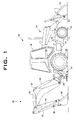
- Fig. 1 is a representation of an exemplary machine suitable for being provided with ride control.
- Fig. 2 is an exemplary schematical representation of a fluid system for the machine of Fig. 1 .
- the machine 10 may have a body 12.
- the body 12 may be a single piece or may include a set of subassemblies and or components.
- the body 12 may include a frame 14, an operator platform 16, a pair of front wheels 18, a pair of rear wheels 20 and a stabilizing arrangement 19.
- the body 12 may provide a first connection 21 for connecting a first work arm 22.
- the first work arm 22 may be a front mounted loader arm provided with any suitable attachment 24 such as for example a work tool like a bucket.
- the first work arm may be lifted and lowered via the first cylinder 26. It is to be understood that the first cylinder 26 may be read as at least one first cylinder 26 as there may be a plurality of first cylinders 26, for example two first cylinders 26, one at either side of the body 12. The operation of the first cylinder 26 will be discussed in more detail later on.
- the body 12 may further provide a second connection 29 for connecting a second work arm generally designated with the numeral 30.
- the second work arm 30 may be mounted at, or adjacent to, a rear end of the machine 10 and may for example include a boom 32, a stick 34, and a linkage 36 for connecting to any suitable attachment 38 such as for example a work tool like a bucket.
- the second work arm 30 may be lifted and lowered by a second cylinder 126 connected between the body 12 and the boom 32.
- the operation of the second cylinder 126 will be discussed in more detail later on.
- the relative orientation of the boom 32, the stick 34 and linkage 36 may be altered by using a third cylinder 35 between the boom 32 and the stick 34 and a fourth cylinder 37 between the stick 34 and linkage 36.
- each of the cylinders 126, 35 and 37 may in fact be a plurality of similar cylinders performing a similar function.
- the first cylinder 26 may be configured to operate and hence lift and lower the first work arm 22.
- the first cylinder 26 may be part of a fluid system generally designated 50 of which an exemplary embodiment is shown in Fig. 2 .
- the fluid system 50 also includes an exemplary embodiment of the fluid circuit relating to the second cylinder 126.
- the circuits for the first and second cylinders 26 and 126 may be substantially similar in concept only the circuit leading to the first cylinder 26 will be discussed in more detail.
- Like elements in both circuits for the first and second cylinders 26 and 126 will have like numbering. Where necessary to distinguish, similar components in the circuits for the first or second cylinders 26, 126 will for convenience accordingly be named first and second respectively.
- the first cylinder 26 may have a lift chamber 52 and a lowering chamber 54 and may be provided with a piston 56 and a rod 58.
- the first cylinder 26 may operate in a conventional manner such that when the lift chamber 52 is pressurized the first cylinder 26 is extended and when the lowering chamber 54 is pressurized the first cylinder 26 is retracted.
- the first cylinder 26 may also be arranged such that the head end of the first cylinder 26 is attached to the first work arm 22.
- the lift chamber 52 of the first cylinder 26 may be fluidly connected to a ride control valve 60 via a fluid line 62.
- the lowering chamber 54 may be fluidly connected to the ride control valve 60 via a fluid line 64.
- the lift chamber 52 may further be connected to a directional valve 66 via a fluid line 68.
- the lowering chamber 54 may further be fluidly connected to the directional valve 66 via a fluid line 70.
- the fluid lines 62 and 68 may be partially combined into a single fluid line as shown in Fig. 2 , but they may also be run separately.
- the fluid lines 64 and 70 may be partially combined into a single fluid line as shown in Fig. 2 , but they may also be run separately.
- the ride control valve 60 may further be fluidly connected to a low pressure region 72 via a fluid line 71.
- the low pressure region 72 may be of any suitable type and may for example be a fluid reservoir or a set of either interlinked or independent fluid reservoirs.
- the ride control valve 60 may further be connected to an accumulator 74 via a fluid line 76.
- the accumulator 74 may be a conventional accumulator having a pre-charged and compressible gas chamber filled with a gas such as nitrogen.
- the accumulator 74 may also be an arrangement of multiple accumulators.
- the first and second accumulators 74 and 174 may be shared by both the first and second cylinders 26 and 126.
- the first and second accumulators 74 and 174 may be a single accumulator shared by both the first and second cylinders 26 and 126.
- first and second ride control valves 66 and 166 may be the same valve.
- the ride control valve 60 may include a single valve or an arrangement of valves.
- the ride control valve 60 may be controlled in any suitable manner and may for example be biased to one position by springs 78 and actuated by actuators 80.
- the actuators 80 may be solenoids.
- the ride control valve 60 may be configured to assume a plurality of positions and may therefore be provided with first, second and third portions 60a, 60b and 60c representing first, second and third valve positions.
- the fluid system 50 may be simplified by omitting either portion 60a or portion 60b.
- the lift chamber 52 is fluidly connected to both the first accumulator 74 and the lowering chamber 54.
- the active portion of the valve arrangement 60 is portion 60b.
- the ride control valve 60 fluidly connects the lift chamber 52 to the accumulator 74.
- the lowering chamber 54 is fluidly disconnected from the accumulator 74.
- the ride control valve 60 may be configured such that the lowering chamber 54 is fluidly connected to the low pressure region 72 when the ride control valve 60 is in the second position, but the ride control valve 60 may alternatively be configured to fluidly disconnect the lowering chamber 54 from the low pressure region 72.
- the lift and lowering chambers 52 and 54 are both disconnected from the accumulator 74.
- the lift and lowering chambers 52 and 54 may be either fluidly connected to one another or they may be fluidly disconnected from one another.
- the directional valve 66 may further be fluidly connected to the low pressure region 72 via a fluid line 75.
- the directional valve 66 may further be connected to a source of pressurized fluid 71 via a fluid line 73.
- the source of pressurized fluid 71 may for example be a fluid pump or multiple fluid pumps that may be either interlinked or operate independently from one another.
- the directional valve 66 may be configured to pressurize at least one of the lift and lowering chambers 52 and 54 of the first cylinder 26 to, for example, lift and lower the first work arm 22.
- the directional valve 66 may include a single valve or a combination of valves.
- the directional valve 66 may be controlled in any suitable manner and may for example be biased to one position by springs 84 and actuated by actuators 86.
- the actuators 86 may be solenoids.
- the directional valve 66 may be configured to assume a plurality of positions and may therefore be provided with first, second and third portions 66a, 66b and 66c representing first, second and third valve positions.
- the directional valve 66 may be proportional such that the directional valve 66 can assume positions intermediate of the first, second and third valve positions.
- the active portion of the directional valve 66 is portion 66a.
- the directional valve 66 in the first position fluidly connects the lift chamber 52 to the source of pressurized fluid 71.
- the lowering chamber 54 may be fluidly connected to the low pressure region 72.
- the lowering chamber 54 is fluidly connected to the source of pressurized fluid 71 whilst the lift chamber 52 may be fluidly connected to the low pressure region 72.
- the lift and lowering chambers 52 and 54 may both be disconnected from both the source of pressurized fluid 71 and the low pressure region 72.
- the directional control valve arrangements 66 and 166 may be the same valve.
- the machine 10 may be provided with a control arrangement 90, for example an electronic control arrangement, for controlling one or more functions of the machine 10.
- the control arrangement 90 may be one or more electronic control units and/or one or more relay based system. It may for example be configured to receive and process signals and/or instructions from an input means 92.
- the input means 92 may include multiple operator controls such as a joystick or switch arrangements.
- the input means 92 may be used to select one or more settings associated with at least one ride control setting.
- the control arrangement may be configured to receive and process a signal from a first sensing arrangement 93.
- the first sensing arrangement sensor 93 may be any type of equipment capable of providing an indication of a speed of the machine 10.
- the first sensing arrangement 93 may include a radar arrangement for detecting ground speed.
- the first sensing arrangement may include sensor for measuring a velocity parameter of the machine itself, such as for example an angular speed of a rotating component such as a transmission shaft.
- the machine 10 may further be provided with a second sensing arrangements 95 for providing data regarding the loading of either or both of the first and second work arms 22 and 30.
- the second sensing arrangement 95 may for example include one or more pressure sensors configured to measure fluid pressures associated with any of the first and second cylinders 26 and 33.
- the second sensing arrangement 95 may include sensors capable of measuring deflection of components of the machine 10. For example strain gauges (not shown) may provide an indication about the deflection of for example a portion of the first connection 21 and/or the second connection 29.
- the machine 10 may be configured to prevent pressurization of at least one of the lift and lowering chambers 52 and 54 via the directional valve 66 when the ride control valve 60 is in the first position.
- the machine 10 may use the a control arrangement 90 for controlling the directional valve 22 and the ride control valve 66.
- control arrangement 90 may be configured to provide for an interlock between the actuators 80 and 86. If for example one of the actuators 86 is actuated, the control arrangement 90 may be configured to prevent any of the actuators 80 from being actuated.
- the input means 92 may include separate controls to separately control the fluid circuits associated with the first and second cylinders 26 and 126. In an embodiment the input means 92 may include combined controls for the fluid circuits associated with the first and second cylinders 26 and 126.
- the machine 10 may be configured to prevent at least one of the lift and lowering chambers 52 and 54 to be fluidly connected with at least one of the low pressure region 72 or the first accumulator 74 when the directional valve 66 is in the first or the second position. This may again be achieved via the control arrangement 90 which can be configured to prevent or enable certain combinations of simultaneous actuation of any of the actuators 80 with any of the actuators 86.
- the machine 10 may be configured to enable pressurization of at least one of the lift and lowering chambers 52 and 54 via the directional valve 66 when the ride control valve 60 is in the first position. This may for example be achieved by enabling the directional valve 66 to assume an intermediate position between the first and the third position, i.e. intermediate of the portions 66a and 66c, such that the fluid line 73 is fluidly connected with the fluid line 68, but that the fluid line 75 is not yet fluidly connected with the fluid line 70.
- the machine 10 may be configured to prevent pressurization of at least one of the lift and lowering chambers 52 and 54 via the directional valve 66 when the ride control valve 60 is in the second position.
- the machine 10 may be configured to enable pressurization of at least one of the lift and lowering chambers 52 and 54 via the directional valve 66 when the ride control valve 60 is in the second position. This may for example be achieved by placing the directional valve 66 in the first or second position.
- a machine such as exemplary machine 10 provided with an exemplary fluid system 50 may be used in mobile operations. During such operations the machine 10 may travel between multiple locations. Depending on factors such as for example job requirements, distances to be traveled, surroundings and payload the operator may drive the machine 10 at a particular speed or within a range of speeds and with a particular payload associated with either of the first and second attachments 24 and 38. Under certain conditions the machine 10 may demonstrate a forward/rearward rocking action, which may be aggravated by conditions such as rough terrain, high speed travel or high payloads. This rocking motion may be aggravated by the inertia of the first and second work arms 22 and 30 relative to the rest of the machine 10.
- Engaging ride control may prevent, overcome or alleviate at least some of the rocking motion as it may allow some of the energy involved a rocking movement to be absorbed by the accumulators 74 and/or 174.
- Ride control may be engaged by connecting at least one of the first and second cylinders 26 and 34 with at least one of the accumulators 74 and 174. This will enable a limited displacement of fluid from the first and second cylinders 26 and 126 to the accumulators 74 and 174 wherein energy carried by the displaced fluid may be used to compress the gas in the accumulators 74 and 174 thereby providing a balanced suspension effect for the first and second work arms 22 and 30.
- the fluid line 62,76 between the lift chamber 52 of the first cylinder 26 and the first accumulator 74 may be opened to enable a transfer of fluid.
- the fluid line 162, 176 may be opened between the lift chamber 152 of the second cylinder 126 and second accumulator 74.
- the ride control setting such as for example during a load-and-dig cycle in which the machine 10 may shuttle forwards and backwards to alternately dig and load.
- Such cycle may require extensive use of the first work arm 22, whilst the second work arm 30 is not being used or only to a limited extent.
- the ride control settings may further be adjusted by selectively using one of the first and second portions 60a and 60b and of the first and second portions 160a and 160b of the first and second directional control valves 66 and 166 respectively.
- Selecting for example the first portions 60a as the active portion may change the ride control characteristics of the system as compared to the situation in which the second portion 60b is the active portion, as not only the first accumulator 74 is connected to the lift chamber 52, but additionally the lift chamber 52 and the first accumulator 74 are fluidly connected to the lowering chamber 54.
- this may be experienced as the suspensive effect of the ride control being "harder” or "softer", i.e. changing the rate and/or amount of allowable travel of the work arm 22. It is to be understood that the aforementioned is equally applicable to the use of the first and second portions 160a and 160b.
- the first sensing arrangement 93 may provide a signal indicative of the speed of the machine 10.
- the control arrangement 90 may be configured to automatically open at least one of the fluid line between the lift chamber 52 of the first cylinder 26 and the first accumulator 74 and the fluid line between the lift chamber 152 of the second cylinder 133 and the second accumulator 174 in response to detecting machine movement.
- the ride control may be progressively engaged in relation to machine speed. For example at low machine speed the first lift chamber 52 and the first accumulator 74 may be fluidly connected.
- the control arrangement 90 detects a higher machine speed it may for example fluidly connect the first fluid chamber 52 to both the first accumulator 74 and the first lowering chamber 54.
- control arrangement 90 may then engage the second lift chamber 152, the second lowering chamber 154 and the second accumulator 174 in any order and as desired. It is to be understood that depending on machine configuration it may be desirable to operate the various steps of the ride control system in a different order as described above. For example, in an embodiment it may be preferred to first engage the portion of the fluid system associated with the second work arm 33. It may also be desirable to fluidly connect as a first step both a lift chamber 52, 152 and a lowering chamber 54, 154 with an accumulator 74, 174, rather than just fluidly connecting a lift chamber with an accumulator 74, 174.
- a load on either or both of the first and second work arms may be determined using the second sensing arrangement 95.
- the control arrangement 90 may simultaneously or sequentially engage the various possible options provided by the fluid system 50 for providing ride control to either or both the first and second work arms 22 and 30. For example in a scenario wherein the machine 10 is loaded with a particular load associated with the first work arm 22 the control arrangement 90 may determine that only fluidly connecting the first cylinder 26 to the accumulator 74 may be preferred. If then during driving the control arrangement 90 determines the loading on the accumulator 74 is too high, it may decide to also fluidly connect the second cylinder 33 to the accumulator 174.
- the machine 10 with the fluid system 50 offers many options in ride control settings.
- the settings may be automatically adjusted, by for example providing the interlocking arrangements as discussed above.
- the settings may me manually adjusted by enabling the operator to select between all possible options.
- the system may be semi-automatically controlled whereby for example the operator may select certain setting(s) but wherein the electronic control arrangements 90 may override some settings or suggest different settings.
Landscapes
- Engineering & Computer Science (AREA)
- General Engineering & Computer Science (AREA)
- Mining & Mineral Resources (AREA)
- Civil Engineering (AREA)
- Structural Engineering (AREA)
- Physics & Mathematics (AREA)
- Fluid Mechanics (AREA)
- Mechanical Engineering (AREA)
- Operation Control Of Excavators (AREA)
- Fluid-Pressure Circuits (AREA)
Abstract
Description
- This disclosure relates to ride control and in particular, but not exclusively, to machines having selective ride controls.
- Mobile machines and especially those equipped with a work arm may be provided with systems known as ride control. Such systems commonly fluidly connect a hydraulic accumulator to a hydraulic cylinder provided to support the work arm. During movement of the machine fluid can transfer between the cylinder and the accumulator allowing for a travel of the work arm relative to the rest of the machine. By providing such arrangement it is found that a fore/aft rocking movement of the machine may be reduced as the ride control will absorb some of the energy created by the inertial forces between the work arm and the rest of the machine.
- From
US patent no. 5,992,146 a variable rate ride control system is known in which an accumulator arrangement is connected through a first valve mechanism to the loaded end of an actuator to provide a cushion or damping of the sudden changes in force. The first valve mechanism controls the magnitude of the damping in response to the rate of flow between the actuator and the accumulator arrangement via an infinitely variable flow control mechanism. However, the system is fairly costly, requires complex controls and does provide only limited selectivity. - The current disclosure aims to improve upon some or all of the disadvantages associated with the prior art.
- In a first aspect there is disclosed a machine having a first work arm (22), at least one first cylinder (26) having a lift chamber (52) configured for receiving pressurised fluid so as to lift the first work arm (26) and a first accumulator (74) associated with the lift chamber (52) of the first cylinder (26). The machine further has a second work arm (30), at least one second cylinder (126) having a lift chamber (152) configured for receiving pressurised fluid so as to lift the second work arm (30) and a second accumulator (174) associated with the lift chamber (152) of the second cylinder (126). A control arrangement (90) is provided for selectively fluidly connecting one or both of the first and second accumulators (74, 174) with their associated lift chambers (52,152).
- In a second aspect there is disclosed a method of operating a machine having a first work arm associated with a lift chamber of a first cylinder for lifting the first work arm The lift chamber of the first cylinder is selectively fluidly connectable to a first accumulator via a fluid line. The machine further has a second work arm associated with a lift chamber of a second cylinder for lifting the second work arm, the lift chamber of the second cylinder being selectively fluidly connectable to a second accumulator via a fluid line. The method includes opening the fluid line between the lift chamber of the first cylinder and the first accumulator, opening the fluid line between the lift chamber of the second cylinder and the second accumulator and moving the machine in a selected direction.
- Other features and aspects of this disclosure will be apparent from the following description and the accompanying drawings.
-
Fig. 1 is a representation of an exemplary machine suitable for being provided with ride control. -
Fig. 2 is an exemplary schematical representation of a fluid system for the machine ofFig. 1 . - Referring to
Fig. 1 an embodiment of the current disclosure is shown in context of a construction machine known as a backhoe loader. It is to be understood however that the embodiment ofFig. 1 is exemplary only and that the concept is equally applicable to any other suitable machine. Themachine 10 may have abody 12. Thebody 12 may be a single piece or may include a set of subassemblies and or components. For example, thebody 12 may include aframe 14, anoperator platform 16, a pair offront wheels 18, a pair ofrear wheels 20 and a stabilizingarrangement 19. Thebody 12 may provide afirst connection 21 for connecting afirst work arm 22. Thefirst work arm 22 may be a front mounted loader arm provided with anysuitable attachment 24 such as for example a work tool like a bucket. The first work arm may be lifted and lowered via thefirst cylinder 26. It is to be understood that thefirst cylinder 26 may be read as at least onefirst cylinder 26 as there may be a plurality offirst cylinders 26, for example twofirst cylinders 26, one at either side of thebody 12. The operation of thefirst cylinder 26 will be discussed in more detail later on. - The
body 12 may further provide asecond connection 29 for connecting a second work arm generally designated with thenumeral 30. Thesecond work arm 30 may be mounted at, or adjacent to, a rear end of themachine 10 and may for example include aboom 32, astick 34, and alinkage 36 for connecting to anysuitable attachment 38 such as for example a work tool like a bucket. Thesecond work arm 30 may be lifted and lowered by a second cylinder 126 connected between thebody 12 and theboom 32. The operation of the second cylinder 126 will be discussed in more detail later on. The relative orientation of theboom 32, thestick 34 andlinkage 36 may be altered by using athird cylinder 35 between theboom 32 and thestick 34 and afourth cylinder 37 between thestick 34 andlinkage 36. Again it is to be understood that each of thecylinders - The
first cylinder 26 may be configured to operate and hence lift and lower thefirst work arm 22. Thefirst cylinder 26 may be part of a fluid system generally designated 50 of which an exemplary embodiment is shown inFig. 2 . Thefluid system 50 also includes an exemplary embodiment of the fluid circuit relating to the second cylinder 126. As the circuits for the first andsecond cylinders 26 and 126 may be substantially similar in concept only the circuit leading to thefirst cylinder 26 will be discussed in more detail. Like elements in both circuits for the first andsecond cylinders 26 and 126 will have like numbering. Where necessary to distinguish, similar components in the circuits for the first orsecond cylinders 26, 126 will for convenience accordingly be named first and second respectively. - The
first cylinder 26 may have alift chamber 52 and a loweringchamber 54 and may be provided with apiston 56 and arod 58. Thefirst cylinder 26 may operate in a conventional manner such that when thelift chamber 52 is pressurized thefirst cylinder 26 is extended and when the loweringchamber 54 is pressurized thefirst cylinder 26 is retracted. Although shown inFig.1 as having the rod end of thefirst cylinder 26 attached to thefirst work arm 22, thefirst cylinder 26 may also be arranged such that the head end of thefirst cylinder 26 is attached to thefirst work arm 22. - The
lift chamber 52 of thefirst cylinder 26 may be fluidly connected to aride control valve 60 via afluid line 62. The loweringchamber 54 may be fluidly connected to theride control valve 60 via afluid line 64. Thelift chamber 52 may further be connected to adirectional valve 66 via afluid line 68. The loweringchamber 54 may further be fluidly connected to thedirectional valve 66 via afluid line 70. Thefluid lines Fig. 2 , but they may also be run separately. Similarly, thefluid lines Fig. 2 , but they may also be run separately. - The
ride control valve 60 may further be fluidly connected to alow pressure region 72 via afluid line 71. Thelow pressure region 72 may be of any suitable type and may for example be a fluid reservoir or a set of either interlinked or independent fluid reservoirs. Theride control valve 60 may further be connected to anaccumulator 74 via afluid line 76. Theaccumulator 74 may be a conventional accumulator having a pre-charged and compressible gas chamber filled with a gas such as nitrogen. Theaccumulator 74 may also be an arrangement of multiple accumulators. In an embodiment the first andsecond accumulators second cylinders 26 and 126. In an embodiment the first andsecond accumulators second cylinders 26 and 126. - In an embodiment the first and second
ride control valves - The
ride control valve 60 may include a single valve or an arrangement of valves. Theride control valve 60 may be controlled in any suitable manner and may for example be biased to one position bysprings 78 and actuated byactuators 80. Theactuators 80 may be solenoids. - In the exemplary embodiment of
Fig. 2 theride control valve 60 may be configured to assume a plurality of positions and may therefore be provided with first, second andthird portions - In other embodiments the
fluid system 50 may be simplified by omitting eitherportion 60a orportion 60b. - By selecting a first position of the
ride control valve 60 and thereby using thefirst portion 60a, thelift chamber 52 is fluidly connected to both thefirst accumulator 74 and the loweringchamber 54. In the second position, the active portion of thevalve arrangement 60 isportion 60b. By selectingportion 60b, theride control valve 60 fluidly connects thelift chamber 52 to theaccumulator 74. Simultaneously the loweringchamber 54 is fluidly disconnected from theaccumulator 74. Theride control valve 60 may be configured such that the loweringchamber 54 is fluidly connected to thelow pressure region 72 when theride control valve 60 is in the second position, but theride control valve 60 may alternatively be configured to fluidly disconnect the loweringchamber 54 from thelow pressure region 72. - By selecting a third position of the
valve arrangement 60 and thereby using thethird portion 60c, the lift and loweringchambers accumulator 74. In the third position the lift and loweringchambers - The
directional valve 66 may further be fluidly connected to thelow pressure region 72 via a fluid line 75. Thedirectional valve 66 may further be connected to a source ofpressurized fluid 71 via afluid line 73. The source ofpressurized fluid 71 may for example be a fluid pump or multiple fluid pumps that may be either interlinked or operate independently from one another. - The
directional valve 66 may be configured to pressurize at least one of the lift and loweringchambers first cylinder 26 to, for example, lift and lower thefirst work arm 22. - The
directional valve 66 may include a single valve or a combination of valves. Thedirectional valve 66 may be controlled in any suitable manner and may for example be biased to one position bysprings 84 and actuated byactuators 86. Theactuators 86 may be solenoids. - In the exemplary embodiment of
Fig. 2 thedirectional valve 66 may be configured to assume a plurality of positions and may therefore be provided with first, second andthird portions directional valve 66 may be proportional such that thedirectional valve 66 can assume positions intermediate of the first, second and third valve positions. In the first position, the active portion of thedirectional valve 66 isportion 66a. By selectingportion 66a, thedirectional valve 66 in the first position fluidly connects thelift chamber 52 to the source ofpressurized fluid 71. Simultaneously the loweringchamber 54 may be fluidly connected to thelow pressure region 72. - By selecting a second position of the
directional valve 66 and thereby using thesecond portion 66b, the loweringchamber 54 is fluidly connected to the source ofpressurized fluid 71 whilst thelift chamber 52 may be fluidly connected to thelow pressure region 72. - By selecting a third position of the
valve arrangement 66 and thereby using thethird portion 66c, the lift and loweringchambers pressurized fluid 71 and thelow pressure region 72. - In an embodiment the directional
control valve arrangements - The
machine 10 may be provided with acontrol arrangement 90, for example an electronic control arrangement, for controlling one or more functions of themachine 10. In an embodiment thecontrol arrangement 90 may be one or more electronic control units and/or one or more relay based system. It may for example be configured to receive and process signals and/or instructions from an input means 92. In an embodiment, the input means 92 may include multiple operator controls such as a joystick or switch arrangements. In an embodiment the input means 92 may be used to select one or more settings associated with at least one ride control setting. In an embodiment the control arrangement may be configured to receive and process a signal from afirst sensing arrangement 93. The firstsensing arrangement sensor 93 may be any type of equipment capable of providing an indication of a speed of themachine 10. In an embodiment thefirst sensing arrangement 93 may include a radar arrangement for detecting ground speed. In another embodiment the first sensing arrangement may include sensor for measuring a velocity parameter of the machine itself, such as for example an angular speed of a rotating component such as a transmission shaft. - In an embodiment the
machine 10 may further be provided with a second sensing arrangements 95 for providing data regarding the loading of either or both of the first andsecond work arms second cylinders machine 10. For example strain gauges (not shown) may provide an indication about the deflection of for example a portion of thefirst connection 21 and/or thesecond connection 29. - In an embodiment wherein the
fluid system 50 is fitted onto themachine 10, themachine 10 may be configured to prevent pressurization of at least one of the lift and loweringchambers directional valve 66 when theride control valve 60 is in the first position. For example, themachine 10 may use the acontrol arrangement 90 for controlling thedirectional valve 22 and theride control valve 66. - In an embodiment the
control arrangement 90 may be configured to provide for an interlock between theactuators actuators 86 is actuated, thecontrol arrangement 90 may be configured to prevent any of theactuators 80 from being actuated. In an embodiment the input means 92 may include separate controls to separately control the fluid circuits associated with the first andsecond cylinders 26 and 126. In an embodiment the input means 92 may include combined controls for the fluid circuits associated with the first andsecond cylinders 26 and 126. - In an embodiment wherein the
fluid system 50 is fitted onto themachine 10, themachine 10 may be configured to prevent at least one of the lift and loweringchambers low pressure region 72 or thefirst accumulator 74 when thedirectional valve 66 is in the first or the second position. This may again be achieved via thecontrol arrangement 90 which can be configured to prevent or enable certain combinations of simultaneous actuation of any of theactuators 80 with any of theactuators 86. - In an embodiment wherein the
fluid system 50 is fitted onto themachine 10, themachine 10 may be configured to enable pressurization of at least one of the lift and loweringchambers directional valve 66 when theride control valve 60 is in the first position. This may for example be achieved by enabling thedirectional valve 66 to assume an intermediate position between the first and the third position, i.e. intermediate of theportions fluid line 73 is fluidly connected with thefluid line 68, but that the fluid line 75 is not yet fluidly connected with thefluid line 70. - In an embodiment wherein the
fluid system 50 is fitted onto themachine 10, themachine 10 may be configured to prevent pressurization of at least one of the lift and loweringchambers directional valve 66 when theride control valve 60 is in the second position. - In an embodiment wherein the
fluid system 50 is fitted onto themachine 10, themachine 10 may be configured to enable pressurization of at least one of the lift and loweringchambers directional valve 66 when theride control valve 60 is in the second position. This may for example be achieved by placing thedirectional valve 66 in the first or second position. - Industrial Applicability
- A machine such as
exemplary machine 10 provided with anexemplary fluid system 50 may be used in mobile operations. During such operations themachine 10 may travel between multiple locations. Depending on factors such as for example job requirements, distances to be traveled, surroundings and payload the operator may drive themachine 10 at a particular speed or within a range of speeds and with a particular payload associated with either of the first andsecond attachments machine 10 may demonstrate a forward/rearward rocking action, which may be aggravated by conditions such as rough terrain, high speed travel or high payloads. This rocking motion may be aggravated by the inertia of the first andsecond work arms machine 10. Engaging ride control may prevent, overcome or alleviate at least some of the rocking motion as it may allow some of the energy involved a rocking movement to be absorbed by theaccumulators 74 and/or 174. Ride control may be engaged by connecting at least one of the first andsecond cylinders accumulators second cylinders 26 and 126 to theaccumulators accumulators second work arms - For example, during operation it may be desirable to provide ride control to both the first and
second work arms fluid line lift chamber 52 of thefirst cylinder 26 and thefirst accumulator 74 may be opened to enable a transfer of fluid. At some stage which may happen before, during or after the opening of thefluid line fluid line lift chamber 152 of the second cylinder 126 andsecond accumulator 74. These two events of connecting the first andsecond cylinders 26 and 126 with theaccumulators machine 10 is moving in a selected direction. - During operation it may further be desirable to change the ride control setting, such as for example during a load-and-dig cycle in which the
machine 10 may shuttle forwards and backwards to alternately dig and load. Such cycle may require extensive use of thefirst work arm 22, whilst thesecond work arm 30 is not being used or only to a limited extent. In such a situation it may be desirable to provide ride control, but it may be undesirable to connect thefirst cylinder 26 with thefirst accumulator 74. This may for example be undesirable if there is a risk of the digging being more difficult to perform or control, or a heavy payload on thework arm 22 creating a situation in which thefirst accumulator 74 may be near or exceeding its maximum capacity. In this scenario it may be preferred to disable the fluid flow between the first cylinder and thefirst accumulator 74 but still enabling the fluid connection between the second cylinder 126 and thesecond accumulator 74. - In addition to the foregoing the ride control settings may further be adjusted by selectively using one of the first and
second portions second portions directional control valves first portions 60a as the active portion may change the ride control characteristics of the system as compared to the situation in which thesecond portion 60b is the active portion, as not only thefirst accumulator 74 is connected to thelift chamber 52, but additionally thelift chamber 52 and thefirst accumulator 74 are fluidly connected to the loweringchamber 54. Depending on the characteristics of themachine 10, this may be experienced as the suspensive effect of the ride control being "harder" or "softer", i.e. changing the rate and/or amount of allowable travel of thework arm 22. It is to be understood that the aforementioned is equally applicable to the use of the first andsecond portions - In one operation it may be preferred disable ride control to at least one of the first and
second work arms second work arms directional control valves second work arms - In an embodiment the
first sensing arrangement 93 may provide a signal indicative of the speed of themachine 10. Thecontrol arrangement 90 may be configured to automatically open at least one of the fluid line between thelift chamber 52 of thefirst cylinder 26 and thefirst accumulator 74 and the fluid line between thelift chamber 152 of the second cylinder 133 and thesecond accumulator 174 in response to detecting machine movement. In such an embodiment the ride control may be progressively engaged in relation to machine speed. For example at low machine speed thefirst lift chamber 52 and thefirst accumulator 74 may be fluidly connected. When thecontrol arrangement 90 detects a higher machine speed it may for example fluidly connect thefirst fluid chamber 52 to both thefirst accumulator 74 and the first loweringchamber 54. At subsequent events such as even higher machine speeds thecontrol arrangement 90 may then engage thesecond lift chamber 152, thesecond lowering chamber 154 and thesecond accumulator 174 in any order and as desired. It is to be understood that depending on machine configuration it may be desirable to operate the various steps of the ride control system in a different order as described above. For example, in an embodiment it may be preferred to first engage the portion of the fluid system associated with thesecond work arm 33. It may also be desirable to fluidly connect as a first step both alift chamber chamber accumulator accumulator - In an embodiment, a load on either or both of the first and second work arms may be determined using the second sensing arrangement 95. Depending on the loading the
control arrangement 90 may simultaneously or sequentially engage the various possible options provided by thefluid system 50 for providing ride control to either or both the first andsecond work arms machine 10 is loaded with a particular load associated with thefirst work arm 22 thecontrol arrangement 90 may determine that only fluidly connecting thefirst cylinder 26 to theaccumulator 74 may be preferred. If then during driving thecontrol arrangement 90 determines the loading on theaccumulator 74 is too high, it may decide to also fluidly connect thesecond cylinder 33 to theaccumulator 174. - It is to be understood that the
machine 10 with thefluid system 50 offers many options in ride control settings. In an embodiment the settings may be automatically adjusted, by for example providing the interlocking arrangements as discussed above. In an embodiment the settings may me manually adjusted by enabling the operator to select between all possible options. In another embodiment the system may be semi-automatically controlled whereby for example the operator may select certain setting(s) but wherein theelectronic control arrangements 90 may override some settings or suggest different settings. - Although the preferred embodiments of this invention have been described herein, improvements and modifications may be incorporated without departing from the scope of the following claims.
Claims (13)
- A machine comprising:a first work arm (22);at least one first cylinder (26) having a lift chamber (52) configured for receiving pressurised fluid so as to lift said first work arm (26);a first accumulator (74) associated with said lift chamber (52) of said first cylinder (26);a second work arm (30);at least one second cylinder (126) having a lift chamber (152) configured for receiving pressurised fluid so as to lift said second work arm (30);a second accumulator (174) associated with said lift chamber (152) of said second cylinder (126);a control arrangement (90) for selectively fluidly connecting one or both of said first and second accumulators (74, 174) with their associated lift chambers (52,152).
- A machine according to any of the preceding claims, wherein said first and second accumulator (74, 174) are the same accumulator.
- A machine according to any of the preceding claims, wherein said control arrangement (90) is further configured to selectively fluidly disconnect one of said first and second lift chambers (52, 152) from its associated accumulator (74, 174) whilst maintaining the fluid connection between the other one of said first and second lift chambers (52, 152) and its associated accumulator (74, 174).
- A machine according to any of the preceding claims, wherein said first cylinder (26) further has a lowering chamber (54) and said control arrangement (90) is further configured to selectively connect both said lift chamber (52) and said lowering chamber (54) of said first cylinder (26) to said accumulator 74.
- A machine according to any of the preceding claims, wherein said second cylinder (126) further has a lowering chamber (154) and said control arrangement (90) is further configured to selectively connect both said lift chamber (152) and said lowering chamber (154) of said second cylinder (26) to said accumulator 174.
- A machine according to any of the preceding claims, wherein said machine further includes a first ride control valve (60) for selectively fluidly connecting said first accumulator (74) with the first lift chamber (52), a pump (71) and a first directional valve arrangement (66) for selectively directing pressurised fluid from said pump (71) to said first lift and lowering chambers (52, 54) and wherein said control arrangement (90) is further configured to provide an interlock between said first directional valve arrangement (66) and said first ride control valve (60).
- A machine according to claim 6, wherein said machine further comprises a second directional valve arrangement (166) for selectively directing pressurised fluid from said pump (71) to said second lift and lowering chambers (152, 154) and wherein said control arrangement (90) is further configured to provide an interlock between said second directional valve arrangement (166) and said second ride control valve (160).
- A method of operating a machine (10) having a first work arm (22) associated with a lift chamber (52) of a first cylinder (26) for lifting said first work arm (22), said lift chamber (52) of said first cylinder (26) being selectively fluidly connectable to a first accumulator (74) via a fluid line (62, 76), the machine (10) further having a second work arm (30) associated with a lift (152) chamber of a second cylinder (126) for lifting said second work arm (30), said lift chamber (152) of said second cylinder (126) being selectively fluidly connectable to a second accumulator (164) via a fluid line (162, 176), the method comprising:opening said fluid line (62, 76) between said lift chamber (52) of said first cylinder (26) and said first accumulator (74);opening said fluid (162, 176) line between said lift chamber (152) of said second cylinder (126) and said second accumulator (174);moving said machine (10) in a selected direction.
- A method according to claim 8, further comprising:closing said fluid line (62, 76) between said lift chamber (52) of said first cylinder (26) and said first accumulator (74) whilst keeping open said fluid line (162, 176) between said lift chamber (152) of said second cylinder (126) and said second accumulator (174).
- A method according to any of claims 8-9, wherein said machine (10) further includes a first directional valve (66) for lifting and lowering said first work arm (22), the method further comprising closing said fluid line (62, 76) between said lift chamber (52) of said first cylinder (26) and said first accumulator (74) when said first directional valve (66) is operating to lift or lower said first work arm (22).
- A method according to any of claims 8-10, wherein said machine (10) further includes a second directional valve (166) for lifting and lowering said second work arm (30), the method further comprising closing said fluid line (162, 176) between said lift chamber (152) of said second cylinder (126) and said second accumulator (174) when said second directional valve (166) is operating to lift or lower said second work arm (30).
- A method according to any of claims 8-11, further comprising
detecting that said machine (10) is moving;
opening at least one of said fluid line (62, 76) between said lift chamber (52) of said first cylinder (26) and said first accumulator (74) and said fluid line (162, 176) between said lift chamber (152) of said second cylinder (126) and said second accumulator (174) in response to detecting machine movement. - A method according to any of claims 8-12, further comprising
detecting that a load is placed on said machine (10);
opening at least one of said fluid line (62, 76) between said lift chamber (52) of said first cylinder (26) and said first accumulator (74) and said fluid line (162, 176) between said lift chamber (152) of said second cylinder (126) and said second accumulator (174) in response to detecting said load.
Priority Applications (2)
| Application Number | Priority Date | Filing Date | Title |
|---|---|---|---|
| EP07150379A EP2072692B1 (en) | 2007-12-21 | 2007-12-21 | Machine having selective ride control |
| US12/314,876 US8307641B2 (en) | 2007-12-21 | 2008-12-18 | Machine having selective ride control |
Applications Claiming Priority (1)
| Application Number | Priority Date | Filing Date | Title |
|---|---|---|---|
| EP07150379A EP2072692B1 (en) | 2007-12-21 | 2007-12-21 | Machine having selective ride control |
Publications (2)
| Publication Number | Publication Date |
|---|---|
| EP2072692A1 true EP2072692A1 (en) | 2009-06-24 |
| EP2072692B1 EP2072692B1 (en) | 2012-08-01 |
Family
ID=39272134
Family Applications (1)
| Application Number | Title | Priority Date | Filing Date |
|---|---|---|---|
| EP07150379A Active EP2072692B1 (en) | 2007-12-21 | 2007-12-21 | Machine having selective ride control |
Country Status (2)
| Country | Link |
|---|---|
| US (1) | US8307641B2 (en) |
| EP (1) | EP2072692B1 (en) |
Cited By (3)
| Publication number | Priority date | Publication date | Assignee | Title |
|---|---|---|---|---|
| CN102865261A (en) * | 2011-07-06 | 2013-01-09 | 林德材料处理有限责任公司 | Hydrostatic driving system |
| WO2013155178A1 (en) * | 2012-04-11 | 2013-10-17 | Clark Equipment Company | Lift arm suspension system for a power machine |
| CN103590306A (en) * | 2013-11-20 | 2014-02-19 | 山东理工大学 | Hydraulic device for rotary road building equipment |
Families Citing this family (8)
| Publication number | Priority date | Publication date | Assignee | Title |
|---|---|---|---|---|
| WO2013103954A2 (en) * | 2012-01-05 | 2013-07-11 | Parker-Hannifin Corporation | Electro-hydraulic system with float function |
| EP2662142B1 (en) * | 2012-05-10 | 2015-11-18 | Sandvik Intellectual Property AB | Hydraulic system for controlling a jaw crusher |
| WO2016176547A1 (en) * | 2015-04-29 | 2016-11-03 | Clark Equipment Company | Ride control system for power machine |
| US10030364B2 (en) | 2015-10-26 | 2018-07-24 | Caterpillar Inc. | Hydraulic system having automatic ride control |
| JP6716449B2 (en) * | 2016-12-28 | 2020-07-01 | 株式会社クボタ | Hydraulic system of work machine |
| US11421399B2 (en) | 2019-10-31 | 2022-08-23 | Deere & Company | Load sensitive ride system for a vehicle |
| US11441293B2 (en) | 2019-10-31 | 2022-09-13 | Deere & Company | Adjustable ride control system |
| US11781573B2 (en) * | 2020-07-23 | 2023-10-10 | Parker-Hannifin Corporation | System, valve assembly, and methods for oscillation control of a hydraulic machine |
Citations (5)
| Publication number | Priority date | Publication date | Assignee | Title |
|---|---|---|---|---|
| JPH06264467A (en) | 1993-03-12 | 1994-09-20 | Komatsu Ltd | Working machine support device for bulldozer |
| US5992146A (en) | 1996-04-12 | 1999-11-30 | Caterpillar Inc. | Variable rate ride control system |
| US20030213238A1 (en) * | 2002-05-17 | 2003-11-20 | Caterpillar Inc | Hydraulic regeneration system |
| US20040006980A1 (en) * | 2002-06-22 | 2004-01-15 | Deere & Company, A Delaware Corporation | Hydraulic control arrangement for a mobile operating machine |
| US20070186548A1 (en) * | 2006-01-30 | 2007-08-16 | Caterpillar Inc. And Shin Caterpillar Mitsubishi Ltd. | Hydraulic regeneration system |
Family Cites Families (5)
| Publication number | Priority date | Publication date | Assignee | Title |
|---|---|---|---|---|
| DE19823347A1 (en) * | 1998-05-13 | 1999-11-18 | Claas Ohg | Device for the control and adjustment of working cylinders |
| US6167701B1 (en) * | 1998-07-06 | 2001-01-02 | Caterpillar Inc. | Variable rate ride control |
| JP4456078B2 (en) * | 2003-10-10 | 2010-04-28 | 株式会社小松製作所 | Driving vibration control device for work vehicle |
| US7621124B2 (en) * | 2004-10-07 | 2009-11-24 | Komatsu Ltd. | Travel vibration suppressing device for working vehicle |
| JP4685417B2 (en) * | 2004-11-16 | 2011-05-18 | 日立建機株式会社 | Hydraulic control device for work vehicle |
-
2007
- 2007-12-21 EP EP07150379A patent/EP2072692B1/en active Active
-
2008
- 2008-12-18 US US12/314,876 patent/US8307641B2/en active Active
Patent Citations (5)
| Publication number | Priority date | Publication date | Assignee | Title |
|---|---|---|---|---|
| JPH06264467A (en) | 1993-03-12 | 1994-09-20 | Komatsu Ltd | Working machine support device for bulldozer |
| US5992146A (en) | 1996-04-12 | 1999-11-30 | Caterpillar Inc. | Variable rate ride control system |
| US20030213238A1 (en) * | 2002-05-17 | 2003-11-20 | Caterpillar Inc | Hydraulic regeneration system |
| US20040006980A1 (en) * | 2002-06-22 | 2004-01-15 | Deere & Company, A Delaware Corporation | Hydraulic control arrangement for a mobile operating machine |
| US20070186548A1 (en) * | 2006-01-30 | 2007-08-16 | Caterpillar Inc. And Shin Caterpillar Mitsubishi Ltd. | Hydraulic regeneration system |
Cited By (6)
| Publication number | Priority date | Publication date | Assignee | Title |
|---|---|---|---|---|
| CN102865261A (en) * | 2011-07-06 | 2013-01-09 | 林德材料处理有限责任公司 | Hydrostatic driving system |
| CN102865261B (en) * | 2011-07-06 | 2017-03-01 | 林德液压两合公司 | Hydrostatic drive system |
| WO2013155178A1 (en) * | 2012-04-11 | 2013-10-17 | Clark Equipment Company | Lift arm suspension system for a power machine |
| US9932215B2 (en) | 2012-04-11 | 2018-04-03 | Clark Equipment Company | Lift arm suspension system for a power machine |
| CN103590306A (en) * | 2013-11-20 | 2014-02-19 | 山东理工大学 | Hydraulic device for rotary road building equipment |
| CN103590306B (en) * | 2013-11-20 | 2015-10-14 | 山东理工大学 | A kind of hydraulic means for rotary road building equipment |
Also Published As
| Publication number | Publication date |
|---|---|
| US20090158726A1 (en) | 2009-06-25 |
| US8307641B2 (en) | 2012-11-13 |
| EP2072692B1 (en) | 2012-08-01 |
Similar Documents
| Publication | Publication Date | Title |
|---|---|---|
| EP2072692B1 (en) | Machine having selective ride control | |
| US8751117B2 (en) | Method for controlling a movement of a vehicle component | |
| EP2543777B1 (en) | Damper operation control device for a work vehicle, and damper operation control method | |
| EP3203089B1 (en) | Workmachine comprising a hydraulic drive system | |
| US9932721B2 (en) | System, working machine comprising the system, and method of springing an implement of a working machine during transport | |
| US6185493B1 (en) | Method and apparatus for controlling an implement of a work machine | |
| JP6092790B2 (en) | Hydraulic control system with cylinder stagnation strategy | |
| CN111139882B (en) | System and method for improving stability of work machine based on operating value | |
| JP4243366B2 (en) | Method and apparatus for controlling work machine tools | |
| US10954654B2 (en) | Hydraulic derate stability control and calibration | |
| CN101889117B (en) | A method for when necessary automatically limiting a pressure in a hydrualic system during operation | |
| AU2004276616A1 (en) | Hydraulic control device of industrial machinery | |
| EP3505688B1 (en) | System for controlling construction machinery and method for controlling construction machinery | |
| JPWO2016051815A1 (en) | Working machine hydraulic system and working machine | |
| KR102564414B1 (en) | Travel contorl system for construction machinery and travel control method for construction machinery | |
| EP1600419A1 (en) | Hydraulic control device of hydraulic working machine | |
| CN107735530B (en) | Load sensing hydraulic system for construction machine and method of controlling load sensing hydraulic system | |
| JPH1113087A (en) | Method and device for controlling work tool of work machine with linkage angle | |
| KR20190043561A (en) | Hydraulic drives of working machines | |
| JP2011245909A (en) | Outrigger control device | |
| EP4230809A1 (en) | Hydraulic control system for a machine, machine and method for controlling boom and attachment movements of a machine | |
| JP7274997B2 (en) | Hydraulic system of work equipment | |
| WO2021182421A1 (en) | Work vehicle | |
| JP2019065997A (en) | Hydraulic system of work machine | |
| EP3967884A1 (en) | Hydraulic control device for work machine |
Legal Events
| Date | Code | Title | Description |
|---|---|---|---|
| PUAI | Public reference made under article 153(3) epc to a published international application that has entered the european phase |
Free format text: ORIGINAL CODE: 0009012 |
|
| AK | Designated contracting states |
Kind code of ref document: A1 Designated state(s): AT BE BG CH CY CZ DE DK EE ES FI FR GB GR HU IE IS IT LI LT LU LV MC MT NL PL PT RO SE SI SK TR |
|
| AX | Request for extension of the european patent |
Extension state: AL BA HR MK RS |
|
| 17P | Request for examination filed |
Effective date: 20091126 |
|
| 17Q | First examination report despatched |
Effective date: 20091223 |
|
| AKX | Designation fees paid |
Designated state(s): AT BE BG CH CY CZ DE DK EE ES FI FR GB GR HU IE IS IT LI LT LU LV MC MT NL PL PT RO SE SI SK TR |
|
| GRAP | Despatch of communication of intention to grant a patent |
Free format text: ORIGINAL CODE: EPIDOSNIGR1 |
|
| GRAS | Grant fee paid |
Free format text: ORIGINAL CODE: EPIDOSNIGR3 |
|
| GRAA | (expected) grant |
Free format text: ORIGINAL CODE: 0009210 |
|
| AK | Designated contracting states |
Kind code of ref document: B1 Designated state(s): AT BE BG CH CY CZ DE DK EE ES FI FR GB GR HU IE IS IT LI LT LU LV MC MT NL PL PT RO SE SI SK TR |
|
| REG | Reference to a national code |
Ref country code: GB Ref legal event code: FG4D |
|
| REG | Reference to a national code |
Ref country code: CH Ref legal event code: EP Ref country code: AT Ref legal event code: REF Ref document number: 568798 Country of ref document: AT Kind code of ref document: T Effective date: 20120815 |
|
| REG | Reference to a national code |
Ref country code: IE Ref legal event code: FG4D |
|
| REG | Reference to a national code |
Ref country code: DE Ref legal event code: R096 Ref document number: 602007024291 Country of ref document: DE Effective date: 20120927 |
|
| REG | Reference to a national code |
Ref country code: NL Ref legal event code: VDEP Effective date: 20120801 |
|
| REG | Reference to a national code |
Ref country code: AT Ref legal event code: MK05 Ref document number: 568798 Country of ref document: AT Kind code of ref document: T Effective date: 20120801 |
|
| REG | Reference to a national code |
Ref country code: LT Ref legal event code: MG4D Effective date: 20120801 |
|
| PG25 | Lapsed in a contracting state [announced via postgrant information from national office to epo] |
Ref country code: AT Free format text: LAPSE BECAUSE OF FAILURE TO SUBMIT A TRANSLATION OF THE DESCRIPTION OR TO PAY THE FEE WITHIN THE PRESCRIBED TIME-LIMIT Effective date: 20120801 Ref country code: LT Free format text: LAPSE BECAUSE OF FAILURE TO SUBMIT A TRANSLATION OF THE DESCRIPTION OR TO PAY THE FEE WITHIN THE PRESCRIBED TIME-LIMIT Effective date: 20120801 Ref country code: FI Free format text: LAPSE BECAUSE OF FAILURE TO SUBMIT A TRANSLATION OF THE DESCRIPTION OR TO PAY THE FEE WITHIN THE PRESCRIBED TIME-LIMIT Effective date: 20120801 Ref country code: CY Free format text: LAPSE BECAUSE OF FAILURE TO SUBMIT A TRANSLATION OF THE DESCRIPTION OR TO PAY THE FEE WITHIN THE PRESCRIBED TIME-LIMIT Effective date: 20120801 Ref country code: IS Free format text: LAPSE BECAUSE OF FAILURE TO SUBMIT A TRANSLATION OF THE DESCRIPTION OR TO PAY THE FEE WITHIN THE PRESCRIBED TIME-LIMIT Effective date: 20121201 |
|
| PGFP | Annual fee paid to national office [announced via postgrant information from national office to epo] |
Ref country code: FR Payment date: 20121113 Year of fee payment: 6 |
|
| PG25 | Lapsed in a contracting state [announced via postgrant information from national office to epo] |
Ref country code: BE Free format text: LAPSE BECAUSE OF FAILURE TO SUBMIT A TRANSLATION OF THE DESCRIPTION OR TO PAY THE FEE WITHIN THE PRESCRIBED TIME-LIMIT Effective date: 20120801 Ref country code: GR Free format text: LAPSE BECAUSE OF FAILURE TO SUBMIT A TRANSLATION OF THE DESCRIPTION OR TO PAY THE FEE WITHIN THE PRESCRIBED TIME-LIMIT Effective date: 20121102 Ref country code: SE Free format text: LAPSE BECAUSE OF FAILURE TO SUBMIT A TRANSLATION OF THE DESCRIPTION OR TO PAY THE FEE WITHIN THE PRESCRIBED TIME-LIMIT Effective date: 20120801 Ref country code: SI Free format text: LAPSE BECAUSE OF FAILURE TO SUBMIT A TRANSLATION OF THE DESCRIPTION OR TO PAY THE FEE WITHIN THE PRESCRIBED TIME-LIMIT Effective date: 20120801 Ref country code: PL Free format text: LAPSE BECAUSE OF FAILURE TO SUBMIT A TRANSLATION OF THE DESCRIPTION OR TO PAY THE FEE WITHIN THE PRESCRIBED TIME-LIMIT Effective date: 20120801 Ref country code: LV Free format text: LAPSE BECAUSE OF FAILURE TO SUBMIT A TRANSLATION OF THE DESCRIPTION OR TO PAY THE FEE WITHIN THE PRESCRIBED TIME-LIMIT Effective date: 20120801 Ref country code: PT Free format text: LAPSE BECAUSE OF FAILURE TO SUBMIT A TRANSLATION OF THE DESCRIPTION OR TO PAY THE FEE WITHIN THE PRESCRIBED TIME-LIMIT Effective date: 20121203 |
|
| PG25 | Lapsed in a contracting state [announced via postgrant information from national office to epo] |
Ref country code: NL Free format text: LAPSE BECAUSE OF FAILURE TO SUBMIT A TRANSLATION OF THE DESCRIPTION OR TO PAY THE FEE WITHIN THE PRESCRIBED TIME-LIMIT Effective date: 20120801 |
|
| PG25 | Lapsed in a contracting state [announced via postgrant information from national office to epo] |
Ref country code: DK Free format text: LAPSE BECAUSE OF FAILURE TO SUBMIT A TRANSLATION OF THE DESCRIPTION OR TO PAY THE FEE WITHIN THE PRESCRIBED TIME-LIMIT Effective date: 20120801 Ref country code: CZ Free format text: LAPSE BECAUSE OF FAILURE TO SUBMIT A TRANSLATION OF THE DESCRIPTION OR TO PAY THE FEE WITHIN THE PRESCRIBED TIME-LIMIT Effective date: 20120801 Ref country code: ES Free format text: LAPSE BECAUSE OF FAILURE TO SUBMIT A TRANSLATION OF THE DESCRIPTION OR TO PAY THE FEE WITHIN THE PRESCRIBED TIME-LIMIT Effective date: 20121112 Ref country code: EE Free format text: LAPSE BECAUSE OF FAILURE TO SUBMIT A TRANSLATION OF THE DESCRIPTION OR TO PAY THE FEE WITHIN THE PRESCRIBED TIME-LIMIT Effective date: 20120801 Ref country code: RO Free format text: LAPSE BECAUSE OF FAILURE TO SUBMIT A TRANSLATION OF THE DESCRIPTION OR TO PAY THE FEE WITHIN THE PRESCRIBED TIME-LIMIT Effective date: 20120801 |
|
| PG25 | Lapsed in a contracting state [announced via postgrant information from national office to epo] |
Ref country code: SK Free format text: LAPSE BECAUSE OF FAILURE TO SUBMIT A TRANSLATION OF THE DESCRIPTION OR TO PAY THE FEE WITHIN THE PRESCRIBED TIME-LIMIT Effective date: 20120801 Ref country code: IT Free format text: LAPSE BECAUSE OF FAILURE TO SUBMIT A TRANSLATION OF THE DESCRIPTION OR TO PAY THE FEE WITHIN THE PRESCRIBED TIME-LIMIT Effective date: 20120801 |
|
| PLBE | No opposition filed within time limit |
Free format text: ORIGINAL CODE: 0009261 |
|
| STAA | Information on the status of an ep patent application or granted ep patent |
Free format text: STATUS: NO OPPOSITION FILED WITHIN TIME LIMIT |
|
| REG | Reference to a national code |
Ref country code: DE Ref legal event code: R119 Ref document number: 602007024291 Country of ref document: DE |
|
| 26N | No opposition filed |
Effective date: 20130503 |
|
| PG25 | Lapsed in a contracting state [announced via postgrant information from national office to epo] |
Ref country code: MC Free format text: LAPSE BECAUSE OF NON-PAYMENT OF DUE FEES Effective date: 20121231 Ref country code: BG Free format text: LAPSE BECAUSE OF FAILURE TO SUBMIT A TRANSLATION OF THE DESCRIPTION OR TO PAY THE FEE WITHIN THE PRESCRIBED TIME-LIMIT Effective date: 20121101 |
|
| REG | Reference to a national code |
Ref country code: CH Ref legal event code: PL |
|
| REG | Reference to a national code |
Ref country code: DE Ref legal event code: R097 Ref document number: 602007024291 Country of ref document: DE Effective date: 20130503 |
|
| REG | Reference to a national code |
Ref country code: IE Ref legal event code: MM4A |
|
| PG25 | Lapsed in a contracting state [announced via postgrant information from national office to epo] |
Ref country code: CH Free format text: LAPSE BECAUSE OF NON-PAYMENT OF DUE FEES Effective date: 20121231 Ref country code: IE Free format text: LAPSE BECAUSE OF NON-PAYMENT OF DUE FEES Effective date: 20121221 Ref country code: LI Free format text: LAPSE BECAUSE OF NON-PAYMENT OF DUE FEES Effective date: 20121231 Ref country code: DE Free format text: LAPSE BECAUSE OF NON-PAYMENT OF DUE FEES Effective date: 20130702 |
|
| REG | Reference to a national code |
Ref country code: DE Ref legal event code: R119 Ref document number: 602007024291 Country of ref document: DE Effective date: 20130702 |
|
| PG25 | Lapsed in a contracting state [announced via postgrant information from national office to epo] |
Ref country code: MT Free format text: LAPSE BECAUSE OF FAILURE TO SUBMIT A TRANSLATION OF THE DESCRIPTION OR TO PAY THE FEE WITHIN THE PRESCRIBED TIME-LIMIT Effective date: 20120801 |
|
| PG25 | Lapsed in a contracting state [announced via postgrant information from national office to epo] |
Ref country code: TR Free format text: LAPSE BECAUSE OF FAILURE TO SUBMIT A TRANSLATION OF THE DESCRIPTION OR TO PAY THE FEE WITHIN THE PRESCRIBED TIME-LIMIT Effective date: 20120801 |
|
| PG25 | Lapsed in a contracting state [announced via postgrant information from national office to epo] |
Ref country code: LU Free format text: LAPSE BECAUSE OF NON-PAYMENT OF DUE FEES Effective date: 20121221 |
|
| PG25 | Lapsed in a contracting state [announced via postgrant information from national office to epo] |
Ref country code: HU Free format text: LAPSE BECAUSE OF FAILURE TO SUBMIT A TRANSLATION OF THE DESCRIPTION OR TO PAY THE FEE WITHIN THE PRESCRIBED TIME-LIMIT Effective date: 20071221 |
|
| REG | Reference to a national code |
Ref country code: FR Ref legal event code: ST Effective date: 20140829 |
|
| PG25 | Lapsed in a contracting state [announced via postgrant information from national office to epo] |
Ref country code: FR Free format text: LAPSE BECAUSE OF NON-PAYMENT OF DUE FEES Effective date: 20131231 |
|
| PGFP | Annual fee paid to national office [announced via postgrant information from national office to epo] |
Ref country code: GB Payment date: 20221116 Year of fee payment: 16 |
|
| P01 | Opt-out of the competence of the unified patent court (upc) registered |
Effective date: 20230517 |