EP2071363B1 - Lighting grid and method for its operation - Google Patents
Lighting grid and method for its operation Download PDFInfo
- Publication number
- EP2071363B1 EP2071363B1 EP08017078.0A EP08017078A EP2071363B1 EP 2071363 B1 EP2071363 B1 EP 2071363B1 EP 08017078 A EP08017078 A EP 08017078A EP 2071363 B1 EP2071363 B1 EP 2071363B1
- Authority
- EP
- European Patent Office
- Prior art keywords
- transmitter
- pulse
- transmitters
- pulses
- synchronisation
- Prior art date
- Legal status (The legal status is an assumption and is not a legal conclusion. Google has not performed a legal analysis and makes no representation as to the accuracy of the status listed.)
- Active
Links
- 238000000034 method Methods 0.000 title claims description 14
- 238000012544 monitoring process Methods 0.000 claims description 17
- 238000001514 detection method Methods 0.000 claims description 15
- 238000011156 evaluation Methods 0.000 claims description 9
- 230000005540 biological transmission Effects 0.000 description 20
- 238000010586 diagram Methods 0.000 description 8
- 230000001360 synchronised effect Effects 0.000 description 5
- 230000004913 activation Effects 0.000 description 3
- 230000003287 optical effect Effects 0.000 description 3
- 230000005855 radiation Effects 0.000 description 3
- 238000005516 engineering process Methods 0.000 description 2
- 230000036039 immunity Effects 0.000 description 2
- 230000005693 optoelectronics Effects 0.000 description 2
- 238000007493 shaping process Methods 0.000 description 2
- 230000004888 barrier function Effects 0.000 description 1
- 238000011161 development Methods 0.000 description 1
- 230000018109 developmental process Effects 0.000 description 1
- 230000000694 effects Effects 0.000 description 1
- 230000002452 interceptive effect Effects 0.000 description 1
- 230000007257 malfunction Effects 0.000 description 1
- 238000001208 nuclear magnetic resonance pulse sequence Methods 0.000 description 1
- 238000011144 upstream manufacturing Methods 0.000 description 1
Images


Classifications
-
- G—PHYSICS
- G01—MEASURING; TESTING
- G01V—GEOPHYSICS; GRAVITATIONAL MEASUREMENTS; DETECTING MASSES OR OBJECTS; TAGS
- G01V8/00—Prospecting or detecting by optical means
- G01V8/10—Detecting, e.g. by using light barriers
- G01V8/20—Detecting, e.g. by using light barriers using multiple transmitters or receivers
Definitions
- the invention relates to a light grid and a method for operating a light grid.
- the light grid has a transmitter unit and a receiver unit, which are arranged on opposite edges of the monitoring area.
- the transmitter unit has an arrangement of adjacent transmitters that emit light beams.
- the receiver unit has an arrangement of receivers arranged side by side.
- a receiver for forming a beam axis is assigned to each transmitter. When the beam path is clear, the receivers are exposed to the transmitted light beams emitted by the respectively assigned transmitter. If there is an object in the beam path, the beam path of the transmitted light beams from at least one transmitter is interrupted so that they no longer impinge on the assigned receiver or receivers, whereby an object detection signal is generated.
- the transmitters and receivers of the individual beam axes are activated cyclically one after the other.
- the transmitter and receiver are synchronized optically.
- the transmitter of the first beam axis sends out transmitted light beams with a specific identifier.
- the other transmitters send out transmitted light beams with an identical identifier each, which differs from the identifier of the first transmitter.
- the identification of the first sender is that this four Emits transmission light pulses, while the remaining transmitters emit two transmission light pulses.
- the identifier of the first transmitter which differs from the identifier of the other transmitters, can thus be used for optical synchronization of the transmitter and the receiver.
- the DE 10 2005 056 000 A1 describes a light curtain with a transmitter unit with several transmitter elements and a receiver unit with several receiver elements, which form several cooperating pairs, each consisting of a transmitter element and a receiver element.
- a transmitter control and a receiver evaluation unit By means of a transmitter control and a receiver evaluation unit, the pairs can be activated cyclically one after the other to transmit and receive transmit pulses synchronously with this.
- the transmitter control and the receiver evaluation unit are electrically decoupled from one another.
- the transmitter control is designed to send out exactly one transmission pulse per transmission element for each cycle.
- the transmitter control outputs a first synchronization pause after a first transmission pulse for a transmission element in the cycle.
- the transmitter control gives a second synchronization pause after a second transmission pulse with a duration different from the first synchronization pause.
- the receiver evaluation unit can be synchronized to this first and / or second synchronization pause in the cycle as a function of the first and second synchronization pause. All transmission pulses have the same duration and shape.
- This light curtain is that, due to the evaluation of synchronization pauses between the transmission of transmission pulses by two transmission elements, several beam axes, each consisting of a pair of transmission and reception elements, have to be used for synchronization. If only one of these beam axes required for synchronization is permanently blocked by an object interference, synchronization of the light grid is no longer possible.
- the EP 1 772 753 A1 relates to a method for operating a light grid with a predetermined number of pairs of transmitters and receivers that emit light beams and form beam axes. These are activated cyclically one after the other to detect objects in a monitoring area. At least one identifier is impressed on each of the transmitted light beams of the individual beam axes. For the optical synchronization of the transmitter and receiver, at least one arbitrary beam axis is used within a cycle, for which the identification of the transmitted light beams is registered in the assigned receiver. Based on this identifier, these beam axes are clearly assigned within the entirety of the beam axes.
- the DE 199 25 553 A1 relates to an optoelectronic device for detecting objects in a monitoring area with at least two transmitters each emitting sequences of light pulses and at least one receiver receiving light pulses.
- the light pulses emitted by the transmitters are deflected at a deflection element and guided to the receiver, with the light pulses from the various transmitters impinging on the receiver with a time delay.
- the EP 1 118 881 A2 relates to a method for operating an optoelectronic sensor arrangement, in particular a light barrier or a light grid, for determining objects present in a monitoring area.
- a transmitter sequentially sends light pulses at a time interval through the monitoring area to a receiver receiving the light pulses and, depending on the presence of an object in the monitoring area, an object detection signal is emitted by an evaluation unit connected to the receiver.
- the amplitude of the light pulses with an alternating light signal is modulated and the received light pulses are checked for the presence of the alternating light modulation.
- DE 100 33 077 A1 describes a light grid for detecting objects in a monitoring area with a transmitting unit comprising several light transmitters and a receiving unit comprising several light receivers, in which, depending on a synchronization signal transmitted between the transmitting and receiving unit, pairs of light transmitters and Light receivers can be activated, at least one light guide being provided for transmitting the synchronization signal.
- the invention is based on the object of providing a light grid with improved functionality.
- the method according to the invention is used to operate a light grid with a transmitter unit that has a number of transmitters emitting light beams and with a receiver unit that is electrically decoupled from the transmitter unit and has a number of receivers, with one transmitter in each case forming a beam axis with a receiver and the transmitters and receivers of the individual beam axes for the detection of objects in a monitoring area can be activated cyclically one after the other.
- a transmitter control unit is provided in the transmitter unit, by means of which the operation of the transmitter is controlled.
- An activated transmitter emits transmitted light beams in the form of at least one pulse group, a pulse group consisting of a sequence of individual pulses or just one pulse, with all beam axes of the light grid being synchronized using a beam axis.
- the pulses emitted by the transmitter of this beam axis differ with regard to at least one parameter in the form of the duration of the pulses or in the form of the pauses between the pulses of the pulse groups from the pulses of the other beam axes.
- Several beam axes are provided, the transmitters of which emit pulse groups that differ in at least one parameter.
- At least one of these beam axes is optionally used to synchronize the light grid, whereby the transmitters of the beam axes are activated one after the other to synchronize the light grid and the synchronization takes place on the basis of the first free beam axis, the transmitter of which emits a pulse group with a unique identifier, or via the transmitter unit the pulse groups that can be used for synchronization are successively impressed on the transmitters of different beam axes, so that the for synchronization
- the beam axis used varies over time, the variation taking place according to time patterns that can be made as desired by the transmitter control unit.
- all transmitters emit pulse groups that consist of several pulses.
- each transmitter can also emit several pulse groups.
- At least the transmitter of a beam axis can be differentiated from all other transmitters of the light curtain, in that the pauses or distances between the individual pulses or the individual pulse groups of this transmitter differ from the corresponding parameters of the remaining transmitters, so that on the basis of these respective unique parameters this beam axis can be used to synchronize the light curtain.
- all transmitters emit a pulse group with only a single pulse when they are activated.
- the transmitter of the beam axis used for synchronization emits a pulse whose duration differs from the pulses emitted by the other transmitters.
- the beam axis, whose transmitter emits pulses with the individual pulse duration can be distinguished from all others and can thus be used for synchronization. Since the transmitters of all beam axes only emit individual pulses and no additional synchronization pauses are required for synchronization, the transmitters can be controlled with little hardware expenditure. In addition, there is a short cycle time for the cyclical activation of the individual beam axes.
- an essential aspect is that it has a high level of availability, especially when used in safety-related applications, since one beam axis is sufficient to synchronize the light curtain.
- the light curtain is used in particular for the purpose of personal protection, the light curtain being used to monitor safety-critical areas on machines or systems.
- security-relevant object interventions such as the entry of a person into the security-critical area, must be reliably detected so that the object detection signal generated in the light curtain generates a shutdown command for the machine to be monitored in order to exclude hazards for the respective person.
- the entire monitored area covered by the light grid can form such a safety-critical area.
- partial areas of the monitored area covered by the light grid can also form non-safety-critical areas, for example, since non-safety-critical objects such as machine parts or conveyor units penetrate them.
- the light curtain should not respond and the associated triggering of a shutdown command should be avoided, as this would lead to unnecessary downtimes of the machine.
- non-safety-relevant areas of the monitored area covered by the light grid can be masked out by means of a so-called blanking or muting process.
- a so-called blanking or muting process In the case of the beam axes of the light grid, which form the masked-out areas, an interruption of the transmitted light beams by an object interference does not result in a shutdown command for the machine. Only if an object enters a non-blanked area of the light curtain does the interruption of a beam axis in this area result in a shutdown command for the machine.
- Such blanking and muting processes can significantly increase the availability of the machine monitored by the light curtain.
- one or more beam axes can be permanently interrupted by an object interference. If it is precisely these beam axes that are required for synchronization, the light grid can no longer be operated, since these beam axes can no longer be used for synchronization.
- the probability that one of these beam axes will fall into a blanked area and thus be permanently interrupted is relatively high.
- one beam axis is sufficient for synchronization, so that the probability that this beam axis will fall into a blanked area is correspondingly lower.
- the risk that the light grid cannot be synchronized is accordingly reduced, that is to say the availability of the light grid is increased.
- the availability of the light grid according to the invention can be significantly increased if several beam axes are provided, the transmitters of which emit pulse groups that differ in at least one parameter and at least one of these beam axes is optionally used to synchronize the light grid.
- the transmitters of the beam axes are activated one after the other and the synchronization takes place on the basis of the first free beam axis, the transmitter of which emits a pulse group with a unique identifier.
- the synchronization of the light grid is no longer fixed to a beam axis; rather, for synchronization in the light grid, the first free beam axis is automatically used for synchronization from a number of beam axes suitable for synchronization. This leads to a significant increase in availability, because of the variation in the synchronization any subregions of the light grid can now be masked out using the beam axes used.
- the pulses that can be used for synchronization i.e. pulse sequences of at least one pulse group
- the pulses that can be used for synchronization are successively impressed on the transmitters of different beam axes, so that these transmitters transmit light beams in Emit shape of these pulses.
- the light curtain according to the invention has a fail-safe structure to meet the requirements of the respective safety standards.
- the receiver control unit integrated in the receiver unit has a redundant structure, preferably in the form of two computer units that monitor each other cyclically.
- this two-channel receiver control unit not only is a fail-safe evaluation of the received signals of the receiver and thus a fail-safe generation of object detection signals obtained. Rather, the synchronization also takes place in a fail-safe manner, with a synchronization algorithm being implemented for this purpose in the receiver control unit.
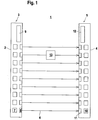
- Figure 1 shows the structure of a light grid 1 for monitoring a monitored area.
- the light grid 1 has a transmitter unit 3 integrated in a first housing 2 and a receiver unit 5 integrated in a second housing 4.
- the transmitter unit 3 has an arrangement of transmitters 7 emitting transmitted light beams 6.
- the transmitters 7 preferably consist of identically designed light-emitting diodes and are arranged lying next to one another at a distance, the transmitters 7 preferably being arranged equidistantly.
- each transmitter 7 is preceded by transmission optics 8.
- the transmission optics 8 are arranged in the area of the front wall of the housing 2 behind an exit window (not shown separately).
- optical axes of the transmitted light beams 6 guided in the monitored area run parallel to one another in the plane of the monitored area.
- the transmitters 7 are controlled by a transmitter control unit 9.
- the transmitters 7 are operated in pulse mode.
- the individual transmitters 7 emit transmitted light beams 6 cyclically one after the other in the form of individual pulses or sequences of pulses, the timing being carried out via the transmitter control unit 9.
- the transmitters 7 are activated one after the other in a predetermined scan direction according to their sequence in the transmitter unit 3 within one cycle.
- the receiver unit 5 has an arrangement of identically designed receivers 10 arranged side by side.
- the receivers 10 preferably each consist of a photodiode and are arranged equidistantly.
- Receiving optics 11 are arranged upstream of each receiver 10.
- a receiver 10 is located opposite a transmitter 7 of the transmitter unit 3.
- the beam shaping of the transmitted light beams 6 is selected in the present case in such a way that when the beam path is free, the transmitted light beams 6 of a transmitter 7 only strike the oppositely arranged receiver 10.
- Each transmitter 7 and the receiver 10 assigned to it forms a beam axis of the light grid 1.
- the entirety of the beam axes of the light grid 1 defines the monitored area covered by it.
- the receivers 10 are controlled via a receiver control unit 12. Furthermore, the received signals present at the output of the receiver 10 are evaluated in the receiver control unit 12. When the beam path of the light grid 1 is clear, the transmitted light beams 6 strike the assigned ones unhindered Receiver 10 and generate there reference received signals corresponding to a free beam path. In particular, the received signals are evaluated in the receiver control unit 12 using a threshold value, the amplitudes of the reference received signals being above the threshold value.
- the beam path of the transmitted light beams 6 from at least one transmitter 7 is interrupted.
- the object consists of a body part 13 of a person.
- the received signal of the assigned receiver 10 is then below the threshold value, that is to say no reference received signals are registered at this receiver 10.
- the interruptions in the beam axes are evaluated in the receiver control unit 12 to generate an object detection signal.
- the object detection signal is designed as a binary switching signal which has the switching distances "0" and "1".
- the switching state "0" corresponds to a free beam path of the light grid 1, that is, no object was registered in the control unit.
- the switching state "1" corresponds to an object intervention in the beam path of the light grid 1.
- the interruption of a beam axis is sufficient for an object intervention to occur.
- the light curtain 1 thus forms a personal protection device that prevents people from being in the area in front of it while the machine is in operation.
- the term light grids also includes, in particular, light curtains in which a large number of transmitters and receivers are provided.
- the light grid 1 has a fail-safe structure.
- the receiver control unit 12 preferably has a redundant structure, in particular in the form of two computer units that monitor each other cyclically.
- the transmitter control unit 9 also has a fail-safe structure, as a result of which a correspondingly safe control of the transmitters 7 of the light curtain 1 is ensured.
- objects can also enter the beam path of the light grid 1 which should not lead to the triggering of an object detection signal.
- objects can be formed by machine parts or moving objects, in particular workpieces to be machined on the machine, which do not endanger people. If such objects occur, it would be unnecessary to stop the machine via the object detection signal.
- blanking areas are defined as sub-areas of the monitoring area within which an object intervention does not lead to the generation of an object detection signal and thus does not lead to the machine being switched off.
- the blanking areas are to be selected so that they correspond exactly to the sub-areas of the monitoring area within which these objects are located.
- the beam axes lying in the respective blanking area are masked out in the evaluation unit so that beam interruptions of these beam axes do not lead to the generation of an object detection signal. Furthermore, the presence of such objects in the monitored area is often required. If, for example, a workpiece were not present in the area of the machine, then there would be a malfunction. In these cases, therefore, an object detection signal is advantageously generated precisely when the object in question does not completely cover the blanking area.
- Figure 2 shows the light grid 1 with a stationary pillar 14 located in the monitoring area as a non-safety-critical object, which defines a blanking area which, in the present case, comprises the first three beam axes of the light grid 1.
- the activation of the transmitters 7 must take place synchronously with the activation of the receivers 10 so that the transmitters 7 and receivers 10 of a beam axis are activated at the same time.
- a synchronization algorithm is implemented in the receiver control unit 12 to carry out the synchronization.
- the synchronization algorithm is formed by software modules by means of which the light curtain 1 is programmed.
- the implementation of the synchronization algorithm in the redundantly constructed receiver control unit 12 ensures fail-safe synchronization of the light curtain 1.
- a beam axis is generally used which can be clearly distinguished from the other beam axes on the basis of the pulse-shaped transmitted light beams 6 emitted by the transmitter 7 of this beam axis. If the pulse-shaped transmitted light beams 6 of the assigned transmitter 7 are recognized at the assigned receiver 10 of this beam axis used for synchronization, then, based on this beam axis, the transmitters 7 and receivers 10 of the other beam axes are activated individually one after the other to operate the light grid 1. The evaluation of whether the transmitted light beams 6 of the assigned transmitter 7 are received at a receiver 10 takes place in the receiver control unit 12 in such a way that corresponding setpoint values are stored there, which are compared with the received signals currently registered at the respective receiver 10.
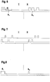
- Figure 3 shows a first embodiment of the transmitter 7 of the light grid 1 according to Figure 1 emitted pulse-shaped transmitted light beams 6.
- the pulse-shaped transmitted light beams 6 emitted by the transmitter 7 used for synchronization are shown with I in each case.
- the pulse-shaped transmitted light rays emitted by the transmitters 7 of all further beam axes are represented by II. This means that all transmitters 7, with the exception of the transmitter 7 used for synchronization, emit pulse-shaped transmitted light beams 7 in an identical manner.
- the transmitter 7 used for synchronization emits transmitted light beams 6 in the form of two pulse groups, the first pulse group comprising two individual pulses and the second pulse group comprising three individual pulses. All pulses have the same pulse width, i.e. the same duration.
- the pulses of the first pulse group are separated by a pause P I or a distance A I.
- pause generally means the time difference between the last pulse of the first pulse group and the first pulse of the following pulse group.
- the term distance generally means the time difference between the first pulse of the first and the following pulse group.
- Pulse groups in the sense of all the exemplary embodiments are sequences of individual pulses, their time intervals being considerably smaller than the time interval to the next pulse group in each case.
- the pulse width of the pulses and the time intervals between the individual pulses of a pulse group are identical to the corresponding values for the transmitter 7 used for synchronization.
- the beam axis used for synchronization can be clearly identified in the receiver control unit 12.
- the different codings of the pulse-shaped transmitted light beams 6 can be easily implemented via the transmitter control unit 9, since all transmitters 7 emit pulses with identical pulse widths, with only the distance or the pause between the pulse groups having to be selected differently to distinguish the transmitted light beams 6 from different transmitters 7 . It is also advantageous that the pulse groups formed by the pulses form individually coded transmitted light beams 6, which can easily be distinguished from incident interfering light in the receiver control unit 12.
- Figure 4 shows a further embodiment of the pulse-shaped transmitted light beams 6 emitted by the transmitters 7 of the light grid 1.
- all transmitters 7 each emit a pulse group consisting of two individual pulses, all pulses having the same pulse width.
- the pulse-shaped transmitted light beams 6 of the transmitter 7 used for synchronization differ in the distance A I or in the pause P I between the pulses from the distance A II or the pause P II of the pulse-shaped Transmitting light beams 6 of the transmitter 7 of all other beam axes. Since each transmitter 7 only emits two individual pulses, a short cycle time of the light grid 1 is obtained. In addition, the pulse groups consisting of two pulses can easily be generated in the transmitter control unit 9.
- FIG Figure 5 shows an extension of the embodiment according to FIG Figure 4 .
- all the transmitters 7 of the light grid 1 emit a pulse group consisting of three pulses, the pulse widths of all the pulses again being identical.
- the distances A 1I , A 2I or pauses P 1I , P 2I of the pulses of the pulse groups differ from the distances A 1II , A 2II or the pauses P 1II , P 2II of the Pulse groups of the transmitted light beams 6 of all other transmitters 7.
- the total transmission duration that is to say the distance between the first and last pulse of a pulse group, is the same for all transmitters 7.
- FIG Figure 6 shows a further embodiment of the transmitters 7 of the light grid 1 according to FIG Figure 1 emitted pulse-shaped transmission light beams 6.
- all transmitters 7 each emit a pulse group consisting of three individual pulses.
- the intervals or pauses between the pulses of the pulse groups are also identical for all transmitters 7.
- Figure 7 illustrates such a situation of two light grids 1, their transmitters 7, according to the embodiment according to FIG Figure 4 , each emit a pulse group consisting of two individual pulses.
- the upper timing diagram shows the pulses of the transmitters 7 of the first light grid 1.
- the lower timing diagram shows the pulses of the transmitters 7 of the second light grid 1.
- FIG Figure 8 shows a further embodiment of the transmission mode of the light curtain 1 according to FIG Figure 1 .
- all transmitters 7 only emit one pulse.
- the pulse of the transmitter 7 used for synchronization thus differs in terms of its pulse width B I from the pulse widths B II of the transmitters 7 of all other beam axes. Because the transmitters 7 only emit individual pulses, a short cycle time of the light grid 1 is obtained. In addition, such individual pulses can be generated with little hardware outlay.
- the same beam axis is always used to synchronize the light grid 1, the pulse-shaped transmitted light beams 6 of this beam axis differing from the pulse-shaped transmitted light beams 6 of all other beam axes.
- this can be the case with the Figures 1 and 2 light grids 1 shown be the uppermost beam axis.
- the beam axis for synchronization can be specified as a function of time via the transmitter control unit 9. This can be done by it takes place that the individual pulses or pulse groups, on the basis of which the synchronization is carried out, are not always impressed on the transmitted light beams 6 of the same transmitter 7. Rather, the transmitters 7 are controlled by the transmitter control unit 9 in such a way that the in areas I of the Figures 3 to 8 The pulses or pulse groups shown, used for synchronization, are emitted by different transmitters 7 in predetermined time cycles.
- a transmitter 7 of a beam axis that is not masked out will emit the pulses or pulse groups used for synchronization. Since the beam axis is not masked out, the receiver 10 receives the pulses or the pulse groups and the synchronization of the light grid 1 can be carried out. In the subsequent operation, the individual transmitters 7 can then emit fixed, constant pulses or pulse groups.
- An alternative solution to the mentioned problem of synchronizing the light grid 1 in the presence of blanked areas is that not only one transmitter 7, but several transmitters 7 emit individual pulses or pulse groups that are different from the pulses or pulse groups of all other transmitters 7. Then not just one but several beam axes can be used to synchronize the light grid 1.
- the light grid 1 is synchronized in such a way that the beam axes of the light grid 1 are activated one after the other and then the first free beam axis, whose transmitter 7 emits pulses or pulse groups with a unique identifier, which are then received by the assigned receiver, are used for synchronization will.
- the synchronization condition stipulated that not only the pulses or pulse groups forming a unique identifier of the transmitter 7 of a beam axis must be received by the assigned receiver 10. Rather, the The synchronization condition can be extended so that the pulses or pulse groups emitted by the transmitter 7 are received by the assigned receiver 10 for at least two beam axes.
- This variant has the advantage that only identifier pairs are formed from the identifiers of the pulses or pulse groups of these transmitters 7 used for synchronization, whereby the identifier supply, i.e. the number of different identifiers available, can be increased.
Landscapes
- Physics & Mathematics (AREA)
- Life Sciences & Earth Sciences (AREA)
- General Life Sciences & Earth Sciences (AREA)
- General Physics & Mathematics (AREA)
- Geophysics (AREA)
- Optical Radar Systems And Details Thereof (AREA)
- Optical Communication System (AREA)
- Burglar Alarm Systems (AREA)
Description
Die Erfindung betrifft ein Lichtgitter sowie ein Verfahren zum Betrieb eines Lichtgitters.The invention relates to a light grid and a method for operating a light grid.
Ein derartiges Lichtgitter ist aus der
Bei dem Betrieb des Lichtgitters werden die Sender und Empfänger der einzelnen Strahlachsen zyklisch nacheinander aktiviert. Die Synchronisierung der Sender und der Empfänger erfolgt auf optischem Weg. Hierzu sendet der Sender der ersten Strahlachse Sendelichtstrahlen mit einer spezifischen Kennung aus. Die übrigen Sender senden Sendelichtstrahlen mit jeweils einer identischen Kennung aus, die sich von der Kennung des ersten Senders unterscheidet. Die Kennung des ersten Senders besteht darin, dass dieser vier Sendelichtimpulse aussendet, während die restlichen Sender zwei Sendelichtpulse emittieren.When the light curtain is in operation, the transmitters and receivers of the individual beam axes are activated cyclically one after the other. The transmitter and receiver are synchronized optically. For this purpose, the transmitter of the first beam axis sends out transmitted light beams with a specific identifier. The other transmitters send out transmitted light beams with an identical identifier each, which differs from the identifier of the first transmitter. The identification of the first sender is that this four Emits transmission light pulses, while the remaining transmitters emit two transmission light pulses.
Somit kann die sich von der Kennung der übrigen Sender unterscheidende Kennung des ersten Senders zur optischen Synchronisierung der Sender und der Empfänger genutzt werden.The identifier of the first transmitter, which differs from the identifier of the other transmitters, can thus be used for optical synchronization of the transmitter and the receiver.
Die
Nachteilig bei diesem Lichtgitter ist, dass bedingt durch die Auswertung von Synchronisationspausen zwischen dem Aussenden von Sendeimpulsen durch zwei Sendelemente immer mehrere von Strahlachsen, die jeweils aus einem Paar eines Sende- und Empfangselements bestehen, zur Synchronisierung herangezogen werden müssen. Wenn nur eine dieser zur Synchronisierung benötigten Strahlachsen durch einen Objekteingriff dauerhaft blockiert ist, ist eine Synchronisierung des Lichtgitters nicht mehr möglich.The disadvantage of this light curtain is that, due to the evaluation of synchronization pauses between the transmission of transmission pulses by two transmission elements, several beam axes, each consisting of a pair of transmission and reception elements, have to be used for synchronization. If only one of these beam axes required for synchronization is permanently blocked by an object interference, synchronization of the light grid is no longer possible.
Die
Die
Die
In
Der Erfindung liegt die Aufgabe zugrunde, ein Lichtgitter mit verbesserter Funktionalität bereitzustellen.The invention is based on the object of providing a light grid with improved functionality.
Zur Lösung dieser Aufgabe sind die Merkmale der Ansprüche 1 und 7 vorgesehen. Vorteilhafte Ausführungsformen und zweckmäßige Weiterbildungen der Erfindung sind in den Unteransprüchen beschrieben.To solve this problem, the features of
Das erfindungsgemäße Verfahren dient zum Betrieb eines Lichtgitters mit einer eine Anzahl von Sendelichtstrahlen emittierenden Sendern aufweisenden Sendereinheit und mit einer von der Sendereinheit elektrisch entkoppelten, eine Anzahl von Empfängern aufweisenden Empfängereinheit, wobei jeweils ein Sender mit einem Empfänger eine Strahlachse bildet und die Sender und Empfänger der einzelnen Strahlachsen zur Erfassung von Objekten in einem Überwachungsbereich zyklisch einzeln nacheinander aktiviert werden. In der Sendereinheit ist eine Sender-Steuereinheit vorgesehen, mittels derer der Betrieb der Sender gesteuert ist. Ein aktivierter Sender emittiert Sendelichtstrahlen in Form von wenigstens einer Pulsgruppe, wobei eine Pulsgruppe aus einer folge von einzelnen Pulsen oder nur aus einem Puls besteht, wobei anhand einer Strahlachse die Synchronisierung aller Strahlachsen des Lichtgitters erfolgt. Die vom Sender dieser Strahlachse emittierten Pulse unterscheiden sich hinsichtlich wenigstens einer Kenngröße in Form der Dauern der Pulse oder in Form der Pausen zwischen den Pulsen der Pulsgruppen von den Pulsen der weiteren Strahlachsen. Mehrere Strahlachsen sind vorgesehen, deren Sender Pulsgruppen emittieren, die sich in wenigstens einer Kenngröße unterscheiden. Zur Synchronisierung des Lichtgitters wird wahlweise wenigstens eine dieser Strahlachsen herangezogen, wobei zur Synchronisierung des Lichtgitters die Sender der Strahlachsen nacheinander aktiviert werden und die Synchronisierung anhand der ersten freien Strahlachse, deren Sender eine Pulsgruppe mit einer eindeutigen Kennung emittiert, erfolgt, oder dass über die Sendereinheit die zur Synchronisierung verwendbaren Pulsgruppen nacheinander den Sendern verschiedener Strahlachsen aufgeprägt werden, so dass die zur Synchronisierung herangezogene Strahlachse zeitlich variiert, wobei die Variation nach Zeitmustern erfolgt, die durch die Sender-Steuereinheit beliebig vorgenommen werden können.The method according to the invention is used to operate a light grid with a transmitter unit that has a number of transmitters emitting light beams and with a receiver unit that is electrically decoupled from the transmitter unit and has a number of receivers, with one transmitter in each case forming a beam axis with a receiver and the transmitters and receivers of the individual beam axes for the detection of objects in a monitoring area can be activated cyclically one after the other. A transmitter control unit is provided in the transmitter unit, by means of which the operation of the transmitter is controlled. An activated transmitter emits transmitted light beams in the form of at least one pulse group, a pulse group consisting of a sequence of individual pulses or just one pulse, with all beam axes of the light grid being synchronized using a beam axis. The pulses emitted by the transmitter of this beam axis differ with regard to at least one parameter in the form of the duration of the pulses or in the form of the pauses between the pulses of the pulse groups from the pulses of the other beam axes. Several beam axes are provided, the transmitters of which emit pulse groups that differ in at least one parameter. At least one of these beam axes is optionally used to synchronize the light grid, whereby the transmitters of the beam axes are activated one after the other to synchronize the light grid and the synchronization takes place on the basis of the first free beam axis, the transmitter of which emits a pulse group with a unique identifier, or via the transmitter unit the pulse groups that can be used for synchronization are successively impressed on the transmitters of different beam axes, so that the for synchronization The beam axis used varies over time, the variation taking place according to time patterns that can be made as desired by the transmitter control unit.
Gemäß einer ersten Variante der Erfindung emittieren alle Sender Pulsgruppen, die aus mehreren Pulsen bestehen. Insbesondere kann jeder Sender auch mehrere Pulsgruppen emittieren.According to a first variant of the invention, all transmitters emit pulse groups that consist of several pulses. In particular, each transmitter can also emit several pulse groups.
In diesem Fall kann wenigstens der Sender einer Strahlachse von allen anderen Sendern des Lichtgitters unterschieden werden, indem sich die Pausen oder Abstände zwischen den einzelnen Pulsen oder den einzelnen Pulsgruppen dieses Senders von den entsprechenden Parametern der restlichen Sender unterscheiden, so dass anhand dieser jeweiligen eindeutigen Kenngröße diese Strahlachse zur Synchronisierung des Lichtgitters herangezogen werden kann.In this case, at least the transmitter of a beam axis can be differentiated from all other transmitters of the light curtain, in that the pauses or distances between the individual pulses or the individual pulse groups of this transmitter differ from the corresponding parameters of the remaining transmitters, so that on the basis of these respective unique parameters this beam axis can be used to synchronize the light curtain.
Gegenüber Lichtgittern, die Einzelpulse aussenden, ergibt sich in diesem Fall eine erhöhte Störsicherheit des Lichtgitters gegen Fremdlichteinstrahlung und insbesondere auch eine erhöhte Unempfindlichkeit gegenüber gegenseitigen Beeinflussungen zweier dicht nebeneinander angeordneter Lichtgitter, bei welchen die Gefahr besteht, dass Sendelichtstrahlen, die von den Sendern eines Lichtgitters emittiert werden, in einem Empfänger des zweiten Lichtgitters eingestrahlt werden. Durch die Verwendung mehrerer Pulse pro Pulsgruppe oder mehrerer Pulsgruppen, die von den Sendern der Lichtgitter emittiert werden, kann eine große Anzahl unterschiedlicher Folgen von Pulsen oder Pulsgruppen generiert werden, so dass in den Lichtgittern eindeutig identifizierbar ist, ob die Sendelichtstrahlen eines Senders korrekt vom zugeordneten Empfänger empfangen werden oder nicht.Compared to light grids that emit individual pulses, this results in increased interference immunity of the light grid against external light radiation and, in particular, increased insensitivity to mutual influences between two light grids arranged close to one another, in which there is a risk that transmitted light beams emitted by the transmitters of a light grid are radiated into a receiver of the second light grid. By using several pulses per pulse group or several pulse groups that are emitted by the transmitters of the light grids, a large number of different sequences of pulses or pulse groups can be generated, so that it can be clearly identified in the light grids whether the transmitted light beams of a transmitter are correctly assigned by the assigned Receivers are received or not.
Gemäß einer besonders einfachen, kostengünstigen Variante der Erfindung emittieren sämtliche Sender bei deren Aktivierung eine Pulsgruppe mit nur einem einzelnen Puls. Der Sender der zur Synchronisierung herangezogenen Strahlachse emittiert einen Puls, dessen Dauer sich von den Pulsen, die von den restlichen Sendern emittiert werden, unterscheiden. Damit ist die Strahlachse, dessen Sender Pulse mit der individuellen Pulsdauer emittiert, von allen anderen unterscheidbar und kann so zur Synchronisierung verwendet werden. Da die Sender aller Strahlachsen nur einzelne Pulse emittieren und zur Synchronisierung keine zusätzlichen Synchronisierpausen benötigt werden, kann die Ansteuerung der Sender mit einem geringen Hardwareaufwand durchgeführt werden. Zudem ergibt sich eine kurze Zykluszeit bei der zyklischen Aktivierung der einzelnen Strahlachsen.According to a particularly simple, cost-effective variant of the invention, all transmitters emit a pulse group with only a single pulse when they are activated. The transmitter of the beam axis used for synchronization emits a pulse whose duration differs from the pulses emitted by the other transmitters. This means that the beam axis, whose transmitter emits pulses with the individual pulse duration, can be distinguished from all others and can thus be used for synchronization. Since the transmitters of all beam axes only emit individual pulses and no additional synchronization pauses are required for synchronization, the transmitters can be controlled with little hardware expenditure. In addition, there is a short cycle time for the cyclical activation of the individual beam axes.
Bei beiden Varianten des erfindungsgemäßen Lichtgitters besteht ein wesentlicher Aspekt darin, dass dieses, insbesondere bei Einsatz in sicherheitstechnischen Applikationen, eine hohe Verfügbarkeit aufweist, da bereits eine Strahlachse zur Synchronisierung des Lichtgitters ausreicht.In both variants of the light curtain according to the invention, an essential aspect is that it has a high level of availability, especially when used in safety-related applications, since one beam axis is sufficient to synchronize the light curtain.
Bei sicherheitstechnischen Applikationen wird das Lichtgitter insbesondere zu Zwecken des Personenschutzes eingesetzt, wobei das Lichtgitter zur Überwachung von sicherheitskritischen Bereichen an Maschinen oder Anlagen eingesetzt wird.In safety-related applications, the light curtain is used in particular for the purpose of personal protection, the light curtain being used to monitor safety-critical areas on machines or systems.
Bei derartigen Anwendungen müssen sicherheitsrelevante Objekteingriffe, wie das Eintreten einer Person in den sicherheitskritischen Bereich, sicher erkannt werden, damit durch das im Lichtgitter generierte Objektfeststellungssignal ein Abschaltbefehl für die zu überwachende Maschine erzeugt wird, um Gefährdungen für die jeweilige Person ausschließen zu können.In such applications, security-relevant object interventions, such as the entry of a person into the security-critical area, must be reliably detected so that the object detection signal generated in the light curtain generates a shutdown command for the machine to be monitored in order to exclude hazards for the respective person.
Je nach Anwendungsfall kann der gesamte mit dem Lichtgitter erfasste Überwachungsbereich einen derartigen sicherheitskritischen Bereich bilden. Während des Betriebs der Maschine können jedoch auch dauernd oder zeitweise Teilbereiche des vom Lichtgitter erfassten Überwachungsbereichs nicht sicherheitskritische Bereiche bilden, da in diesen beispielsweise nichtsicherheitskritische Objekte wie Maschinenteile oder Fördereinheiten eindringen. Bei Eindringen derartiger nichtsicherheitskritischer Objekte ist ein Ansprechen des Lichtgitters und damit verbunden ein Auslösen eines Abschaltbefehls zu vermeiden, da dieser zu unnötigen Stillstandszeiten der Maschine führen würde.Depending on the application, the entire monitored area covered by the light grid can form such a safety-critical area. During the operation of the machine, however, partial areas of the monitored area covered by the light grid can also form non-safety-critical areas, for example, since non-safety-critical objects such as machine parts or conveyor units penetrate them. In the event of such non-safety-critical objects entering, the light curtain should not respond and the associated triggering of a shutdown command should be avoided, as this would lead to unnecessary downtimes of the machine.
In diesen Fällen können derartige nichtsicherheitsrelevante Bereiche des vom Lichtgitter erfassten Überwachungsbereichs mittels eines sogenannten Blanking- oder Mutingverfahrens ausgeblendet werden. Bei den Strahlachsen des Lichtgitters, welche die ausgeblendeten Bereiche bilden, führt eine Unterbrechung der Sendelichtstrahlen durch einen Objekteingriff nicht zu einem Abschaltbefehl für die Maschine. Nur wenn ein Objekt in einen nicht ausgeblendeten Bereich des Lichtgitters eintritt, führt die Unterbrechung einer Strahlachse in diesem Bereich zu einem Abschaltbefehl für die Maschine. Durch derartige Blanking- und Mutingverfahren kann die Verfügbarkeit der mit dem Lichtgitter überwachten Maschine erheblich erhöht werden.In these cases, such non-safety-relevant areas of the monitored area covered by the light grid can be masked out by means of a so-called blanking or muting process. In the case of the beam axes of the light grid, which form the masked-out areas, an interruption of the transmitted light beams by an object interference does not result in a shutdown command for the machine. Only if an object enters a non-blanked area of the light curtain does the interruption of a beam axis in this area result in a shutdown command for the machine. Such blanking and muting processes can significantly increase the availability of the machine monitored by the light curtain.
Jedoch sind derartige ausgeblendete Bereiche für den Betrieb des Lichtgitters selbst problematisch. In einem derartigen ausgeblendeten Bereich des Lichtgitters können eine oder mehrere Strahlachsen durch einen Objekteingriff dauerhaft unterbrochen sein. Wenn nun gerade diese Strahlachsen zur Synchronisierung benötigt werden, ist ein Betrieb des Lichtgitters nicht mehr möglich, da diese Strahlachsen nicht mehr zur Synchronisierung genutzt werden können.However, such blanked areas are problematic for the operation of the light curtain itself. In such a masked-out area of the light grid, one or more beam axes can be permanently interrupted by an object interference. If it is precisely these beam axes that are required for synchronization, the light grid can no longer be operated, since these beam axes can no longer be used for synchronization.
Werden zur Synchronisierung des Lichtgitters zwingend mehrere Strahlachsen benötigt, so ist die Wahrscheinlichkeit, dass eine dieser Strahlachsen in einen ausgeblendeten Bereich fällt und damit dauerhaft unterbrochen ist, relativ groß. Bei dem erfindungsgemäßen Lichtgitter reicht jedoch bereits eine Strahlachse zur Synchronisierung aus, so dass die Wahrscheinlichkeit, dass diese Strahlachse in einen ausgeblendeten Bereich fällt, entsprechend geringer ist. Damit ist die Gefahr, dass das Lichtgitter nicht synchronisierbar ist, entsprechend reduziert, das heißt die Verfügbarkeit des Lichtgitters ist erhöht.If several beam axes are required to synchronize the light grid, the probability that one of these beam axes will fall into a blanked area and thus be permanently interrupted is relatively high. In the light grid according to the invention, however, one beam axis is sufficient for synchronization, so that the probability that this beam axis will fall into a blanked area is correspondingly lower. The risk that the light grid cannot be synchronized is accordingly reduced, that is to say the availability of the light grid is increased.
Die Verfügbarkeit des erfindungsgemäßen Lichtgitters kann signifikant dadurch erhöht werden, wenn mehrere Strahlachsen vorgesehen sind, deren Sender Pulsgruppen emittieren, die sich in wenigstens einer Kenngröße unterscheiden und zur Synchronisierung des Lichtgitters wahlweise wenigstens eine dieser Strahlachsen herangezogen wird.The availability of the light grid according to the invention can be significantly increased if several beam axes are provided, the transmitters of which emit pulse groups that differ in at least one parameter and at least one of these beam axes is optionally used to synchronize the light grid.
Dann werden zur Synchronisierung des Lichtgitters die Sender der Strahlachsen nacheinander aktiviert und die Synchronisierung erfolgt anhand der ersten freien Strahlachse, deren Sender eine Pulsgruppe mit einer eindeutigen Kennung emittiert.Then, to synchronize the light grid, the transmitters of the beam axes are activated one after the other and the synchronization takes place on the basis of the first free beam axis, the transmitter of which emits a pulse group with a unique identifier.
Somit ist die Synchronisierung des Lichtgitters nicht mehr auf eine Strahlachse festgelegt, vielmehr wird zur Synchronisierung im Lichtgitter selbsttätig aus einer Anzahl von für die Synchronisierung geeigneten Strahlachsen die erste freie Strahlachse zur Synchronisierung herangezogen. Dies führt zu einer signifikanten Erhöhung der Verfügbarkeit, da infolge der Variation der zur Synchronisierung herangezogenen Strahlachsen nun beliebige Teilbereiche des Lichtgitters ausgeblendet sein können.Thus, the synchronization of the light grid is no longer fixed to a beam axis; rather, for synchronization in the light grid, the first free beam axis is automatically used for synchronization from a number of beam axes suitable for synchronization. This leads to a significant increase in availability, because of the variation in the synchronization any subregions of the light grid can now be masked out using the beam axes used.
Derselbe vorteilhafte Effekt wird mit einer alternativen Ausgestaltung des Lichtgitters dahingehend erzielt, dass mit der in der Sendereinheit integrierten Sender-Steuereinheit die zur Synchronisierung verwendbaren Pulse, das heißt Pulsfolgen wenigstens einer Pulsgruppe, nacheinander den Sendern verschiedener Strahlachsen aufgeprägt werden, so dass diese Sender Sendelichtstrahlen in Form dieser Pulse emittieren. Damit wird erreicht, dass die zur Synchronisierung herangezogene Strahlachse zeitlich variiert, wobei die Variation nach Zeitmustern erfolgt, die durch die Sender-Steuereinheit beliebig vorgegeben werden können.The same advantageous effect is achieved with an alternative embodiment of the light grid in that with the transmitter control unit integrated in the transmitter unit, the pulses that can be used for synchronization, i.e. pulse sequences of at least one pulse group, are successively impressed on the transmitters of different beam axes, so that these transmitters transmit light beams in Emit shape of these pulses. This ensures that the beam axis used for synchronization varies over time, the variation taking place according to time patterns that can be specified as desired by the transmitter control unit.
Für den Einsatz im Bereich der Sicherheitstechnik, insbesondere im Bereich des Personenschutzes, weist das erfindungsgemäße Lichtgitter einen fehlersicheren Aufbau zur Erfüllung der Anforderungen der jeweiligen Sicherheitsnormen auf. Insbesondere weist die in der Empfängereinheit integrierte Empfänger-Steuereinheit einen redundanten Aufbau auf, vorzugsweise in Form zweier sich gegenseitig zyklisch überwachender Rechnereinheiten. Mit dieser zweikanaligen Empfänger-Steuereinheit wird nicht nur eine fehlersichere Auswertung der Empfangssignale der Empfänger und dadurch eine fehlersichere Generierung von Objektfeststellungssignalen erhalten. Vielmehr erfolgt auch die Synchronisierung fehlersicher, wobei zur Synchronisierung in der Empfänger-Steuereinheit hierzu ein Synchronisationsalgorithmus implementiert ist.For use in the field of safety technology, in particular in the field of personal protection, the light curtain according to the invention has a fail-safe structure to meet the requirements of the respective safety standards. In particular, the receiver control unit integrated in the receiver unit has a redundant structure, preferably in the form of two computer units that monitor each other cyclically. With this two-channel receiver control unit, not only is a fail-safe evaluation of the received signals of the receiver and thus a fail-safe generation of object detection signals obtained. Rather, the synchronization also takes place in a fail-safe manner, with a synchronization algorithm being implemented for this purpose in the receiver control unit.
Die Erfindung wird im Nachstehenden anhand der Zeichnungen erläutert. Es zeigen:
Figur 1- Schematische Darstellung eines Lichtgitters zur Erfassung von Objekten in einem Überwachungsbereich.
Figur 2- Darstellung des Lichtgitters gemäß
Figur 1 bei einem in einer ersten Position liegenden Objekt zur Definition eines BlankingBereichs. Figur 3- Erstes Zeitdiagramm von Pulsgruppen, die von den Sendern des Lichtgitters gemäß
Figur 1 emittiert werden. Figur 4- Erstes Zeitdiagramm von Pulsen einer Pulsgruppe, die von den Sendern des Lichtgitters gemäß
Figur 1 emittiert werden. Figur 5- Zweites Zeitdiagramm von Pulsen einer Pulsgruppe, die von den Sendern des Lichtgitters gemäß
Figur 1 emittiert werden. Figur 6- Drittes Zeitdiagramm von Pulsen einer Pulsgruppe, die von den Sendern des Lichtgitters gemäß
Figur 1 emittiert werden. Figur 7- Zeitdiagramm der von den Sendern zweier Lichtgitter emittierten Pulsen einer Pulsgruppe.
Figur 8- Zeitdiagramm von Einzelpulsen, die von den Sendern des Lichtgitters gemäß
Figur 1 emittiert werden.
- Figure 1
- Schematic representation of a light grid for detecting objects in a monitored area.
- Figure 2
- Representation of the light curtain according to
Figure 1 for an object in a first position to define a blanking area. - Figure 3
- First time diagram of pulse groups generated by the transmitters of the light curtain according to
Figure 1 be emitted. - Figure 4
- First time diagram of pulses of a pulse group, which are sent by the transmitters of the light curtain according to
Figure 1 be emitted. - Figure 5
- Second time diagram of pulses of a pulse group emitted by the transmitters of the light curtain according to FIG
Figure 1 be emitted. - Figure 6
- Third timing diagram of pulses of a pulse group emitted by the transmitters of the light curtain according to
Figure 1 be emitted. - Figure 7
- Time diagram of the pulses of a pulse group emitted by the transmitters of two light grids.
- Figure 8
- Timing diagram of individual pulses emitted by the transmitters of the light curtain in accordance with
Figure 1 be emitted.
Die Sendereinheit 3 weist eine Anordnung von Sendelichtstrahlen 6 emittierenden Sendern 7 auf. Die Sender 7 bestehen vorzugsweise aus identisch ausgebildeten Leuchtdioden und sind in Abstand nebeneinander liegend angeordnet, wobei die Sender 7 vorzugsweise äquidistant angeordnet sind. Zur Strahlformung der Sendelichtstrahlen 6 ist jedem Sender 7 eine Sendeoptik 8 vorgeordnet. Die Sendeoptiken 8 sind im Bereich der Frontwand des Gehäuses 2 hinter einem nicht separat dargestellten Austrittsfenster angeordnet.The
Die optischen Achsen der im Überwachungsbereich geführten Sendelichtstrahlen 6 verlaufen parallel zueinander in der Ebene des Überwachungsbereichs.The optical axes of the transmitted
Die Sender 7 werden von einer Sender-Steuereinheit 9 angesteuert. Im vorliegenden Ausführungsbeispiel werden die Sender 7 im Pulsbetrieb betrieben. Die einzelnen Sender 7 emittieren zyklisch nacheinander Sendelichtstrahlen 6 in Form einzelner Pulse oder Folgen von Pulsen, wobei die Taktung über die Sender-Steuereinheit 9 erfolgt. Dabei werden innerhalb eines Zyklus die Sender 7 entsprechend ihrer Reihenfolge in der Sendereinheit 3 in einer vorgegebenen Scanrichtung nacheinander aktiviert.The
Die Empfängereinheit 5 weist eine Anordnung von identisch ausgebildeten, nebeneinander liegend angeordneten Empfängern 10 auf. Die Empfänger 10 bestehen vorzugsweise jeweils aus einer Fotodiode und sind äquidistant angeordnet. Jedem Empfänger 10 ist eine Empfangsoptik 11 vorgeordnet. Dabei liegt jeweils ein Empfänger 10 einem Sender 7 der Sendereinheit 3 gegenüber. Die Strahlformung der Sendelichtstrahlen 6 ist im vorliegenden Fall derart gewählt, dass bei freiem Strahlengang die Sendelichtstrahlen 6 eines Senders 7 jeweils nur auf den gegenüberliegend angeordneten Empfänger 10 treffen. Jeder Sender 7 und der diesem zugeordnete Empfänger 10 bildet eine Strahlachse des Lichtgitters 1. Die Gesamtheit der Strahlachsen des Lichtgitters 1 definiert den mit diesem erfassten Überwachungsbereich.The
Die Empfänger 10 werden über eine Empfänger-Steuereinheit 12 gesteuert. Weiter werden die am Ausgang der Empfänger 10 anstehenden Empfangssignale in der Empfänger-Steuereinheit 12 ausgewertet. Bei freiem Strahlengang des Lichtgitters 1 treffen die Sendelichtstrahlen 6 ungehindert auf die zugeordneten Empfänger 10 und generieren dort einem freien Strahlengang entsprechende Referenz-Empfangssignale. Insbesondere erfolgt die Bewertung der Empfangssignale in der Empfänger-Steuereinheit 12 mit einem Schwellwert, wobei die Amplituden der Referenz-Empfangssignale oberhalb des Schwellwerts liegen.The
Dringt ein Objekt in den Überwachungsbereich ein, so wird der Strahlengang der Sendelichtstrahlen 6 wenigstens eines Senders 7 unterbrochen. Im vorliegenden Fall besteht das Objekt aus einem Körperteil 13 einer Person. Das Empfangssignal des zugeordneten Empfängers 10 liegt dann unterhalb des Schwellwerts, das heißt an diesem Empfänger 10 werden keine Referenz-Empfangssignale registriert.If an object penetrates the monitored area, the beam path of the transmitted
Die Unterbrechungen der Strahlachsen werden in der Empfänger-Steuereinheit 12 zur Generierung eines Objektfeststellungssignals ausgewertet. Das Objektfeststellungssignal ist als binäres Schaltsignal ausgebildet, welches die Schaltabstände "0" und "1" aufweist. Der Schaltzustand "0" entspricht einem freien Strahlengang des Lichtgitters 1, das heißt in der Steuereinheit wurde kein Objekt registriert. Der Schaltzustand "1" entspricht einem Objekteingriff in den Strahlengang des Lichtgitters 1. Vorzugsweise reicht bereits die Unterbrechung einer Strahlachse aus, damit ein Objekteingriff gegeben ist. Durch die Generierung eines derartigen Objektfeststellungssignals wird ein Abschaltbefehl zum Abschalten einer Maschine oder Anlage generiert, deren Vorfeld mit dem Lichtgitter 1 überwacht wird.The interruptions in the beam axes are evaluated in the
Das Lichtgitter 1 bildet somit eine Personenschutzeinrichtung, die verhindert, dass sich Personen während des Betriebes der Maschine in deren Vorfeld aufhalten. Der Begriff Lichtgitter umfasst insbesondere auch Lichtvorhänge, bei welchen eine große Anzahl von Sendern und Empfängern vorgesehen ist.The
Zur Erfüllung der Anforderungen der relevanten Sicherheitsnormen für den Einsatz im Personenschutz oder allgemein im Bereich der Sicherheitstechnik weist das Lichtgitter 1 einen fehlersicheren Aufbau auf. Vorzugsweise weist dabei die Empfänger-Steuereinheit 12 einen redundanten Aufbau auf, insbesondere in Form von zwei sich gegenseitig zyklisch überwachenden Rechnereinheiten. Zudem weist auch die Sender-Steuereinheit 9 einen fehlersicheren Aufbau auf, wodurch eine entsprechend sichere Ansteuerung der Sender 7 des Lichtgitters 1 gewährleistet ist.To meet the requirements of the relevant safety standards for use in personal protection or in general in the field of safety technology the
In zahlreichen sicherheitstechnischen Applikationen können außer Personen als sicherheitskritische Objekte auch Objekte in den Strahlengang des Lichtgitters 1 eintreten, die nicht zur Auslösung eines Objektfeststellungssignals führen sollen. Beispielsweise können derartige Objekte von Maschinenteilen oder von beweglichen Objekten, insbesondere von an der Maschine zu bearbeitenden Werkstücken, gebildet sein, die nicht zu einer Gefährdung von Personen führen. Bei Eintritt derartiger Objekte wäre ein Stillsetzen der Maschine über das Objektfeststellungssignal unnötig.In numerous safety-related applications, in addition to people as safety-critical objects, objects can also enter the beam path of the
Um derartige unnötige Abschaltbefehle bei Eintritt von derartigen Objekten in den Strahlengang des Lichtgitters 1 zu verhindern, werden Blanking-Bereiche als Teilbereiche des Überwachungsbereiches definiert, innerhalb derer ein Objekteingriff nicht zur Generierung eines Objektfeststellungssignal und damit nicht zu einem Abschalten der Maschine führt.In order to prevent such unnecessary shutdown commands when such objects enter the beam path of the
Die Blanking-Bereiche sind dabei so zu wählen, dass diese exakt den Teilbereichen des Überwachungsbereichs, innerhalb derer diese Objekte liegen, entsprechen.The blanking areas are to be selected so that they correspond exactly to the sub-areas of the monitoring area within which these objects are located.
Zur Unterdrückung eines Objektfeststellungssignals durch derartige Objekte werden die im jeweiligen Blanking- Bereich liegenden Strahlachsen in der Auswerteeinheit ausgeblendet, so dass Strahlunterbrechungen dieser Strahlachsen nicht zur Generierung eines Objektfeststellungssignals führen. Desweiteren wird oftmals sogar das Vorhandensein derartiger Objekte im Überwachungsbereich gefordert. Wäre zum Beispiel ein Werkstück im Bereich der Maschine nicht vorhanden, so läge eine Fehlfunktion vor. Daher wird in diesen Fällen vorteilhaft ein Objektfeststellungssignal gerade dann generiert, wenn das betroffene Objekt nicht den Blanking-Bereich vollständig abdeckt.To suppress an object detection signal by such objects, the beam axes lying in the respective blanking area are masked out in the evaluation unit so that beam interruptions of these beam axes do not lead to the generation of an object detection signal. Furthermore, the presence of such objects in the monitored area is often required. If, for example, a workpiece were not present in the area of the machine, then there would be a malfunction. In these cases, therefore, an object detection signal is advantageously generated precisely when the object in question does not completely cover the blanking area.
Unabhängig davon, ob das Lichtgitter 1 mit ausgeblendeten Bereichen oder ohne ausgeblendete Bereiche betrieben wird, muss die Aktivierung der Sender 7 synchron zur Aktivierung der Empfänger 10 erfolgen, damit jeweils die Sender 7 und Empfänger 10 einer Strahlachse gleichzeitig aktiviert sind.Regardless of whether the
Zur Durchführung der Synchronisierung ist in der Empfänger-Steuereinheit 12 ein Synchronisationsalgorithmus implementiert. Der Synchronisationsalgorithmus ist von Software Modulen gebildet, mittels derer das Lichtgitter 1 programmiert wird. Durch die Implementierung des Synchronisationsalgorithmus in der redundant aufgebauten Empfänger-Steuereinheit 12 ist eine fehlersichere Synchronisierung des Lichtgitters 1 gewährleistet.A synchronization algorithm is implemented in the
Zur Synchronisierung des Lichtgitters 1 wird allgemein eine Strahlachse herangezogen, die anhand der vom Sender 7 dieser Strahlachse emittierten pulsförmigen Sendelichtstrahlen 6 von den anderen Strahlachsen eindeutig unterschieden werden kann. Werden am zugeordneten Empfänger 10 dieser zur Synchronisierung verwendeten Strahlachse die pulsförmigen Sendelichtstrahlen 6 des zugeordneten Senders 7 erkannt, so werden ausgehend von dieser Strahlachse die Sender 7 und Empfänger 10 der weiteren Strahlachsen einzeln nacheinander zum Betrieb des Lichtgitters 1 aktiviert. Die Auswertung, ob an einem Empfänger 10 die Sendelichtstrahlen 6 des zugeordneten Senders 7 empfangen werden, erfolgt in der Empfänger-Steuereinheit 12 derart, dass dort entsprechende Sollwerte abgespeichert sind, die mit den aktuell am jeweiligen Empfänger 10 registrierten Empfangssignalen verglichen werden.To synchronize the
Bei dem Ausführungsbeispiel gemäß
Pulsgruppen im Sinne der sämtlichen Ausführungsbeispiele sind Folgen von Einzel-Pulsen, wobei deren zeitliche Abstände erheblich kleiner sind als der zeitliche Abstand zur jeweils nächsten Pulsgruppe.Pulse groups in the sense of all the exemplary embodiments are sequences of individual pulses, their time intervals being considerably smaller than the time interval to the next pulse group in each case.
Die weiteren Sender 7 emittieren wie der zur Synchronisierung herangezogene Sender 7 jeweils zwei Pulsgruppen, wobei die erste Pulsgruppe wieder zwei einzelne Pulse und die zweite Pulsgruppe wieder drei einzelne Pulse umfasst. Die Pulsbreite der Pulse und die zeitlichen Abstände zwischen den einzelnen Pulsen einer Pulsgruppe sind identisch mit den entsprechenden Größen für den zur Synchronisierung herangezogenen Sender 7.The
Der einzige Unterschied besteht in den Abständen AII beziehungsweise in den Pausen PII zwischen den Pulsgruppen, in welchen sich die pulsförmigen Sendelichtstrahlen 6 dieser Sender 7 von dem Abstand AI beziehungsweise der Pause PI der pulsförmigen Sendelichtstrahlen 6 des zur Synchronisierung herangezogenen Senders 7 unterscheiden.The only difference is in the intervals A II or in the pauses P II between the pulse groups, in which the pulse-shaped
Durch die Auswertung der Abstände AI, AII beziehungsweise der Pausen PI, PII kann in der Empfänger-Steuereinheit 12 die zur Synchronisierung herangezogene Strahlachse eindeutig erkannt werden.By evaluating the distances A I , A II or the pauses P I , P II , the beam axis used for synchronization can be clearly identified in the
Die unterschiedlichen Kodierungen der pulsförmigen Sendelichtstrahlen 6 können über die Sender-Steuereinheit 9 einfach realisiert werden, da sämtliche Sender 7 Pulse mit identischen Pulsbreiten emittieren, wobei zur Unterscheidung der Sendelichtstrahlen 6 unterschiedlicher Sender 7 nur der Abstand oder die Pause zwischen den Pulsgruppen unterschiedlich gewählt werden muss. Weiterhin ist vorteilhaft, dass die von den Pulsen gebildeten Pulsgruppen individuell kodierte Sendelichtstrahlen 6 bilden, die in der Empfänger-Steuereinheit 12 leicht von einfallendem Störlicht unterschieden werden können.The different codings of the pulse-shaped transmitted
In diesem Fall unterscheiden sich die pulsförmigen Sendelichtstrahlen 6 des zur Synchronisierung herangezogenen Senders 7 in dem Abstand AI oder in der Pause PI zwischen den Pulsen von dem Abstand AII oder der Pause PII der pulsförmigen Sendelichtstrahlen 6 der Sender 7 aller anderen Strahlachsen. Da jeder Sender 7 nur zwei einzelne Pulse emittiert, wird eine kurze Zykluszeit des Lichtgitters 1 erhalten. Zudem können die aus zwei Pulsen bestehenden Pulsgruppen einfach in der Sender-Steuereinheit 9 generiert werden.In this case, the pulse-shaped transmitted
Mit den Ausführungsformen gemäß den
Im einfachsten Fall wird immer dieselbe Strahlachse zur Synchronisierung des Lichtgitters 1 herangezogen, wobei sich die pulsförmigen Sendelichtstrahlen 6 dieser Strahlachse von den pulsförmigen Sendelichtstrahlen 6 aller anderen Strahlachsen unterscheiden. Beispielsweise kann dies bei den in den
Probleme bei der Synchronisierung treten dann auf, wenn der ausgeblendete Bereich durch das beispielsweise vom Pfeiler 14 gebildete Objekt, nicht wie in
Zur Lösung dieses Problems kann über die Sender-Steuereinheit 9 die Strahlachse zur Synchronisierung zeitabhängig vorgegeben werden. Dies kann dadurch erfolgen, dass die individuellen Pulse oder Pulsgruppen, anhand derer die Synchronisierung durchgeführt wird, nicht immer den Sendelichtstrahlen 6 desselben Senders 7 aufgeprägt werden. Vielmehr werden die Sender 7 von der Sender-Steuereinheit 9 so angesteuert, dass die in den Bereichen I der
Eine alternative Lösung des genannten Problems der Synchronisierung des Lichtgitters 1 bei vorhandenen ausgeblendeten Bereichen besteht darin, dass nicht nur ein Sender 7, sondern mehrere Sender 7 individuelle Pulse oder Pulsgruppen emittieren, die von den Pulsen oder Pulsgruppen aller anderen Sender 7 unterschiedlich sind. Dann kann nicht nur eine, sondern es können mehrere Strahlachsen zur Synchronisierung des Lichtgitters 1 herangezogen werden. In diesem Fall erfolgt die Synchronisierung des Lichtgitters 1 derart, dass die Strahlachsen des Lichtgitters 1 nacheinander aktiviert werden und dann die erste freie Strahlachse, deren Sender 7 Pulse oder Pulsgruppen mit einer eindeutigen Kennung emittiert, welche dann vom zugeordneten Empfänger empfangen werden, zur Synchronisierung herangezogen wird.An alternative solution to the mentioned problem of synchronizing the
Insbesondere in genannten Fällen, bei welchen die Sender 7 mehrerer Strahlachsen für die Synchronisierung verwendet werden können, kann als Synchronisierungsbedingung gefordert werden, dass nicht nur die eine eindeutige Kennung bildenden Pulse oder Pulsgruppen des Senders 7 einer Strahlachse vom zugeordneten Empfänger 10 empfangen werden müssen. Vielmehr kann die Synchronisierungsbedingung dahin erweitert sein, dass für wenigstens zwei Strahlachsen die vom Sender 7 emittierten Pulse oder Pulsgruppen vom zugeordneten Empfänger 10 empfangen werden. Diese Variante hat den Vorteil, dass nur Kennungspaare von den Kennungen der Pulse oder Pulsgruppen dieser zur Synchronisierung herangezogenen Sender 7 gebildet werden, wodurch der Kennungsvorrat, das heißt die Zahl der zur Verfügung stehenden unterschiedlichen Kennungen, erhöht werden kann.In particular in the cases mentioned, in which the
- (1)(1)
- LichtgitterLight curtain
- (2)(2)
- Gehäusecasing
- (3)(3)
- SendereinheitTransmitter unit
- (4)(4)
- Gehäusecasing
- (5)(5)
- EmpfängereinheitReceiver unit
- (6)(6)
- SendelichtstrahlenTransmitted light rays
- (7)(7)
- SenderChannel
- (8)(8th)
- SendeoptikTransmission optics
- (9)(9)
- Sender-SteuereinheitTransmitter control unit
- (10)(10)
- Empfängerrecipient
- (11)(11)
- EmpfangsoptikReceiving optics
- (12)(12)
- Empfänger-SteuereinheitReceiver control unit
- (13)(13)
- Körperteilbody part
- (14)(14)
- Pfeilerpier
Claims (11)
- A method for operating a light grid having a transmitter unit which has a number of transmitters emitting transmitted light beams, and having a receiver unit which is electrically decoupled from the transmitter unit and has a number of receivers, in each case one transmitter forming a beam axis with one receiver, and the transmitters and receivers of the individual beam axes being activated cyclically individually one after the other for the purpose of detecting objects in a monitoring region, a transmitter control unit (9) being provided in the transmitter unit (3) and being used to control the operation of the transmitters (7),
wherein an activated transmitter (7) emits transmitted light beams (6) in the form of at least one pulse group, wherein a pulse group consists of a sequence of individual pulses or of only one pulse, wherein the synchronisation of all beam axes of the light grid (1) is effected by means of a beam axis, wherein the pulses emitted by the transmitter (7) of this beam axis differ from the pulses of the further beam axes with respect to at least one characteristic variable in the form of the durations of the pulses or in the form of the pauses between the pulses of the pulse groups; and wherein a plurality of beam axes are provided, the transmitters (7) of which emit pulse groups which differ in at least one characteristic quantity, and at least one of these beam axes is selectively used for synchronising the light grid (1), wherein the transmitters (7) of the beam axes are successively activated for synchronising the light grid and the synchronisation takes place with the aid of the first free beam axis, the transmitter (7) of which emits a pulse group with a unique identifier; or
wherein the pulse groups which can be used for synchronisation are successively impressed on the transmitters (7) of different beam axes via the transmitter unit (3), so that the beam axis used for synchronisation varies in time, wherein the variation takes place according to time patterns which can be predetermined as desired by the transmitter control unit (9). - The method according to claim 1, characterised in that, in the case of a pulse duration of this pulse, which is emitted by the transmitter (7) used for synchronisation, differs from the durations of the pulses of the pulse groups which are emitted by the remaining transmitters (7).
- The method according to claim 1, characterised in that each pulse group consists of at least two pulses.
- The method according to claim 3, characterised in that the duration of at least one pulse or at least one of at least one pulse, or at least one pause between two pulses of the pulse group which is emitted by the sensor (7) used for synchronisation (7) used for synchronisation differs from the corresponding parameters of the pulse groups emitted by the remaining transmitters (7).
- The method according to one of claims 3 or 4, characterised in that each activated transmitter (7) emits several groups of pulses, whereby the pauses between two pulse groups are substantially greater than the pauses between pulses of a pulse group, and wherein at least one pause between two between two pulse groups of the transmitter (7) used for the synchronisation (7) used for synchronisation differs from the corresponding size of the other different transmitters (7).
- The method according to one of the claims 1 to 5, characterised in that setpoint values for the pulse groups emitted by the transmitter (7) of the beam axis or of a beam axis used for synchronisation are stored in the receiver unit (5), and in that the pulse groups received at the receiver (10) of this beam axis are compared with the setpoint values and, if there is agreement, synchronisation takes place on the basis of this beam axis.
- A light grid with a transmitter unit having a number of transmitting light beams and with a receiver unit electrically decoupled from the transmitter unit and having a number of receivers, wherein in each case a transmitter forms a beam axis with a receiver and the transmitters and receivers of the individual beam axes are activated cyclically individually one after the other for the detection of objects in a monitoring region, wherein a transmitter control unit (9) is provided in the transmitter unit (3), by means of which the operation of the transmitters (7) is controlled,
wherein an activated transmitter (7) emits transmitted light beams (6) in the form of at least one pulse group, wherein a pulse group consists of a sequence of individual pulses or only of one pulse, wherein the synchronisation of all beam axes of the light grids (1) is effected by means of a beam axis, wherein the pulses emitted by the transmitter (7) of this beam axis differ from the pulses of the other beam axes with respect to at least one characteristic variable in the form of the widths of the pulses or in the form of the pauses or spacings between the pulses of the pulse groups; and
wherein a plurality of beam axes are provided, the transmitters (7) of which emit pulse groups which differ in at least one characteristic quantity, and at least one of these beam axes is selectively used for synchronising the light grid (1), wherein the transmitters (7) of the beam axes are successively activated for synchronising the light grid and the synchronisation takes place with the aid of the first free beam axis, the transmitter (7) of which emits a pulse group with a unique identification; or
wherein the pulse groups which can be used for synchronisation are successively impressed on the transmitters (7) of different beam axes via the transmitter unit (3), so that the beam axis used for synchronisation varies in time, wherein the variation takes place according to time patterns which can be predetermined as desired by the transmitter control unit (9). - The light grid according to claim 7, characterised in that a receiver unit (5) is provided in the receiver unit (5), a receiver control unit (12) is integrated, in which a fail-safe evaluation of the reception signals of the receivers (10) can be carried out.
- The light grid according to claim 8, characterised in that the receiver control unit (12) has a redundant structure in the form of two mutually monitoring computer units.
- The light grid according to one of the claims 8 or 9, characterised in that a synchronisation algorithm is implemented in the receiver control unit (12) is implemented.
- The light grid according to claim 10, characterised in that a fail-safe synchronisation can be carried out with the synchronisation algorithm.
Applications Claiming Priority (1)
| Application Number | Priority Date | Filing Date | Title |
|---|---|---|---|
| DE102007059565A DE102007059565B4 (en) | 2007-12-11 | 2007-12-11 | Light grid and method for its operation |
Publications (3)
| Publication Number | Publication Date |
|---|---|
| EP2071363A2 EP2071363A2 (en) | 2009-06-17 |
| EP2071363A3 EP2071363A3 (en) | 2017-05-24 |
| EP2071363B1 true EP2071363B1 (en) | 2021-07-21 |
Family
ID=40481823
Family Applications (1)
| Application Number | Title | Priority Date | Filing Date |
|---|---|---|---|
| EP08017078.0A Active EP2071363B1 (en) | 2007-12-11 | 2008-09-27 | Lighting grid and method for its operation |
Country Status (2)
| Country | Link |
|---|---|
| EP (1) | EP2071363B1 (en) |
| DE (1) | DE102007059565B4 (en) |
Families Citing this family (11)
| Publication number | Priority date | Publication date | Assignee | Title |
|---|---|---|---|---|
| DE202009007018U1 (en) * | 2009-05-15 | 2010-09-30 | Sick Ag | Optoelectronic sensor arrangement |
| DE102010037681B4 (en) | 2010-09-21 | 2018-12-27 | Sick Ag | Light grid and method for object measurement with a light grid |
| DE102010038118A1 (en) * | 2010-10-12 | 2012-04-12 | Sick Ag | Optoelectronic sensor |
| AT514678A1 (en) * | 2013-05-10 | 2015-02-15 | Thomas Dipl Ing Jerman | Method and device for monitoring a surface |
| EP2813868B1 (en) * | 2013-06-11 | 2021-08-04 | Rockwell Automation Switzerland GmbH | Method for synchronizing optical units of a photoelectric barrier and light curtain |
| DE102013106785B4 (en) | 2013-06-28 | 2018-11-29 | Pilz Auslandsbeteiligungen Gmbh | Method for synchronizing a light grid and light grid based on this method |
| CH714428A1 (en) * | 2017-12-14 | 2019-06-14 | Elesta Gmbh Ostfildern De Zweigniederlassung Bad Ragaz | Method for operating a light barrier arrangement and light barrier arrangement. |
| EP3614182B1 (en) | 2018-08-22 | 2021-03-17 | Leuze electronic GmbH + Co. KG | Optical barrier device |
| CN111981306A (en) * | 2019-05-23 | 2020-11-24 | 上海信索传感器有限公司 | Grating and anti-interference method |
| CN110992585A (en) * | 2019-12-02 | 2020-04-10 | 合肥美的智能科技有限公司 | Container falling detection method and system and container |
| DE202020100872U1 (en) | 2020-02-18 | 2021-05-25 | Leuze Electronic Gmbh + Co. Kg | Light barrier arrangement |
Citations (2)
| Publication number | Priority date | Publication date | Assignee | Title |
|---|---|---|---|---|
| EP1118881A2 (en) * | 2000-01-20 | 2001-07-25 | Sick AG | Opto-electronic sensor arrangement and method for driving an opto-electronic sensor arrangement |
| DE10033077A1 (en) * | 2000-07-07 | 2002-01-17 | Sick Ag | light Curtain |
Family Cites Families (13)
| Publication number | Priority date | Publication date | Assignee | Title |
|---|---|---|---|---|
| US4063085A (en) * | 1975-11-03 | 1977-12-13 | Cometa S. A. | Method of and apparatus for electronic scanning |
| DE3119876A1 (en) * | 1981-05-19 | 1982-12-16 | Wilhelm Ruf KG, 8000 München | Infrared transmitting/receiving system |
| DE3803033A1 (en) * | 1988-02-02 | 1989-08-10 | Sick Erwin Gmbh | LIGHT BARRIER GRID |
| DE3939191C3 (en) | 1989-11-27 | 1996-02-08 | Lumiflex Gmbh & Co Kg Elektron | Multi-beam through-beam sensor |
| DE4141468C2 (en) * | 1991-12-16 | 1994-06-30 | Sick Optik Elektronik Erwin | Optical sensor arrangement and method for its operation |
| DE4224784C2 (en) * | 1992-07-27 | 1995-09-07 | Lumiflex Elektronik Gmbh & Co | Process for operating light barriers, light grids or light curtains |
| DE19510304C1 (en) * | 1995-03-22 | 1996-02-01 | Leuze Electronic Gmbh & Co | Light barrier grid |
| DE19611195C1 (en) * | 1996-03-21 | 1997-06-05 | Lumiflex Elektronik Gmbh & Co | Operating light barrier with at least two synchronously operated transmitter/receiver pairs |
| DE19925553C2 (en) * | 1999-06-04 | 2003-10-16 | Leuze Lumiflex Gmbh & Co Kg | Optoelectric device |
| DE10202305B4 (en) * | 2001-01-24 | 2004-07-08 | Leuze Electronic Gmbh + Co Kg | Optical sensor |
| DE102005047776B4 (en) * | 2005-10-05 | 2007-10-31 | Leuze Lumiflex Gmbh + Co. Kg | Method for operating a light grid |
| DE102005056000A1 (en) | 2005-11-24 | 2007-05-31 | Sick Ag | light Curtain |
| DE102006059322B4 (en) * | 2006-12-15 | 2009-03-26 | Leuze Lumiflex Gmbh + Co. Kg | Method for detecting objects in a surveillance area by means of a light grid |
-
2007
- 2007-12-11 DE DE102007059565A patent/DE102007059565B4/en not_active Revoked
-
2008
- 2008-09-27 EP EP08017078.0A patent/EP2071363B1/en active Active
Patent Citations (2)
| Publication number | Priority date | Publication date | Assignee | Title |
|---|---|---|---|---|
| EP1118881A2 (en) * | 2000-01-20 | 2001-07-25 | Sick AG | Opto-electronic sensor arrangement and method for driving an opto-electronic sensor arrangement |
| DE10033077A1 (en) * | 2000-07-07 | 2002-01-17 | Sick Ag | light Curtain |
Also Published As
| Publication number | Publication date |
|---|---|
| EP2071363A3 (en) | 2017-05-24 |
| DE102007059565B4 (en) | 2010-01-07 |
| EP2071363A2 (en) | 2009-06-17 |
| DE102007059565A1 (en) | 2009-06-18 |
Similar Documents
| Publication | Publication Date | Title |
|---|---|---|
| EP2071363B1 (en) | Lighting grid and method for its operation | |
| DE102006012537B4 (en) | light Curtain | |
| EP2180348B1 (en) | Safety light curtain and corresponding method for monitoring a protection area | |
| DE102012101369B4 (en) | light curtain | |
| DE102007024210A1 (en) | Optoelectronic sensor to protect a hazardous area | |
| EP3014313B1 (en) | Method for synchronizing a light grid | |
| EP3499267A1 (en) | Triangulation light button | |
| DE102007031430B4 (en) | Method for operating a light grid and light grid | |
| DE102016005854A1 (en) | Device and method for monitoring a protected area | |
| EP2362242A1 (en) | Optoelectronic sensor | |
| EP1437542B1 (en) | Light barrier and method for its adjustment | |
| EP3244237B1 (en) | Optical sensor and method of operating an optical sensor | |
| EP1772753B1 (en) | Method for operating a light curtain | |
| DE102018117878A1 (en) | Safety Light Curtain | |
| DE10350927C5 (en) | light Curtain | |
| EP1391752B1 (en) | Light curtain | |
| EP2463687B1 (en) | Optoelectronic sensor | |
| DE102004022812B4 (en) | Method for detecting objects in a surveillance area by means of a light grid | |
| DE202018104258U1 (en) | Safety Light Curtain | |
| EP2259093B1 (en) | Optoelectronic sensor assembly and method for operating the sensor assembly | |
| EP1790999A2 (en) | Light grid | |
| EP3869241B1 (en) | Light barrier device | |
| DE10314581B4 (en) | Opto-electronic monitoring system | |
| EP3168655A1 (en) | Light grid and method for recording objects | |
| EP3594553A1 (en) | Device for monitoring a hazardous area |
Legal Events
| Date | Code | Title | Description |
|---|---|---|---|
| PUAI | Public reference made under article 153(3) epc to a published international application that has entered the european phase |
Free format text: ORIGINAL CODE: 0009012 |
|
| AK | Designated contracting states |
Kind code of ref document: A2 Designated state(s): AT BE BG CH CY CZ DE DK EE ES FI FR GB GR HR HU IE IS IT LI LT LU LV MC MT NL NO PL PT RO SE SI SK TR |
|
| AX | Request for extension of the european patent |
Extension state: AL BA MK RS |
|
| 17P | Request for examination filed |
Effective date: 20140722 |
|
| RBV | Designated contracting states (corrected) |
Designated state(s): AT BE BG CH CY CZ DE DK EE ES FI FR GB GR HR HU IE IS IT LI LT LU LV MC MT NL NO PL PT RO SE SI SK TR |
|
| RAP1 | Party data changed (applicant data changed or rights of an application transferred) |
Owner name: LEUZE ELECTRONIC GMBH + CO. KG |
|
| PUAL | Search report despatched |
Free format text: ORIGINAL CODE: 0009013 |
|
| AK | Designated contracting states |
Kind code of ref document: A3 Designated state(s): AT BE BG CH CY CZ DE DK EE ES FI FR GB GR HR HU IE IS IT LI LT LU LV MC MT NL NO PL PT RO SE SI SK TR |
|
| AX | Request for extension of the european patent |
Extension state: AL BA MK RS |
|
| RIC1 | Information provided on ipc code assigned before grant |
Ipc: G01V 8/20 20060101AFI20170419BHEP |
|
| AKX | Designation fees paid |
Designated state(s): AT BE BG CH CY CZ DE DK EE ES FI FR GB GR HR HU IE IS IT LI LT LU LV MC MT NL NO PL PT RO SE SI SK TR |
|
| AXX | Extension fees paid |
Extension state: BA Extension state: RS Extension state: MK Extension state: AL |
|
| STAA | Information on the status of an ep patent application or granted ep patent |
Free format text: STATUS: EXAMINATION IS IN PROGRESS |
|
| 17Q | First examination report despatched |
Effective date: 20200402 |
|
| STAA | Information on the status of an ep patent application or granted ep patent |
Free format text: STATUS: EXAMINATION IS IN PROGRESS |
|
| GRAP | Despatch of communication of intention to grant a patent |
Free format text: ORIGINAL CODE: EPIDOSNIGR1 |
|
| STAA | Information on the status of an ep patent application or granted ep patent |
Free format text: STATUS: GRANT OF PATENT IS INTENDED |
|
| GRAS | Grant fee paid |
Free format text: ORIGINAL CODE: EPIDOSNIGR3 |
|
| GRAA | (expected) grant |
Free format text: ORIGINAL CODE: 0009210 |
|
| STAA | Information on the status of an ep patent application or granted ep patent |
Free format text: STATUS: THE PATENT HAS BEEN GRANTED |
|
| INTG | Intention to grant announced |
Effective date: 20210526 |
|
| AK | Designated contracting states |
Kind code of ref document: B1 Designated state(s): AT BE BG CH CY CZ DE DK EE ES FI FR GB GR HR HU IE IS IT LI LT LU LV MC MT NL NO PL PT RO SE SI SK TR |
|
| REG | Reference to a national code |
Ref country code: GB Ref legal event code: FG4D Free format text: NOT ENGLISH |
|
| REG | Reference to a national code |
Ref country code: CH Ref legal event code: EP |
|
| REG | Reference to a national code |
Ref country code: DE Ref legal event code: R096 Ref document number: 502008017217 Country of ref document: DE |
|
| REG | Reference to a national code |
Ref country code: AT Ref legal event code: REF Ref document number: 1413090 Country of ref document: AT Kind code of ref document: T Effective date: 20210815 |
|
| REG | Reference to a national code |
Ref country code: IE Ref legal event code: FG4D Free format text: LANGUAGE OF EP DOCUMENT: GERMAN |
|
| REG | Reference to a national code |
Ref country code: LT Ref legal event code: MG9D |
|
| REG | Reference to a national code |
Ref country code: NL Ref legal event code: MP Effective date: 20210721 |
|
| PG25 | Lapsed in a contracting state [announced via postgrant information from national office to epo] |
Ref country code: SE Free format text: LAPSE BECAUSE OF FAILURE TO SUBMIT A TRANSLATION OF THE DESCRIPTION OR TO PAY THE FEE WITHIN THE PRESCRIBED TIME-LIMIT Effective date: 20210721 Ref country code: HR Free format text: LAPSE BECAUSE OF FAILURE TO SUBMIT A TRANSLATION OF THE DESCRIPTION OR TO PAY THE FEE WITHIN THE PRESCRIBED TIME-LIMIT Effective date: 20210721 Ref country code: NL Free format text: LAPSE BECAUSE OF FAILURE TO SUBMIT A TRANSLATION OF THE DESCRIPTION OR TO PAY THE FEE WITHIN THE PRESCRIBED TIME-LIMIT Effective date: 20210721 Ref country code: NO Free format text: LAPSE BECAUSE OF FAILURE TO SUBMIT A TRANSLATION OF THE DESCRIPTION OR TO PAY THE FEE WITHIN THE PRESCRIBED TIME-LIMIT Effective date: 20211021 Ref country code: PT Free format text: LAPSE BECAUSE OF FAILURE TO SUBMIT A TRANSLATION OF THE DESCRIPTION OR TO PAY THE FEE WITHIN THE PRESCRIBED TIME-LIMIT Effective date: 20211122 Ref country code: ES Free format text: LAPSE BECAUSE OF FAILURE TO SUBMIT A TRANSLATION OF THE DESCRIPTION OR TO PAY THE FEE WITHIN THE PRESCRIBED TIME-LIMIT Effective date: 20210721 Ref country code: FI Free format text: LAPSE BECAUSE OF FAILURE TO SUBMIT A TRANSLATION OF THE DESCRIPTION OR TO PAY THE FEE WITHIN THE PRESCRIBED TIME-LIMIT Effective date: 20210721 Ref country code: LT Free format text: LAPSE BECAUSE OF FAILURE TO SUBMIT A TRANSLATION OF THE DESCRIPTION OR TO PAY THE FEE WITHIN THE PRESCRIBED TIME-LIMIT Effective date: 20210721 Ref country code: BG Free format text: LAPSE BECAUSE OF FAILURE TO SUBMIT A TRANSLATION OF THE DESCRIPTION OR TO PAY THE FEE WITHIN THE PRESCRIBED TIME-LIMIT Effective date: 20211021 |
|
| PG25 | Lapsed in a contracting state [announced via postgrant information from national office to epo] |
Ref country code: PL Free format text: LAPSE BECAUSE OF FAILURE TO SUBMIT A TRANSLATION OF THE DESCRIPTION OR TO PAY THE FEE WITHIN THE PRESCRIBED TIME-LIMIT Effective date: 20210721 Ref country code: LV Free format text: LAPSE BECAUSE OF FAILURE TO SUBMIT A TRANSLATION OF THE DESCRIPTION OR TO PAY THE FEE WITHIN THE PRESCRIBED TIME-LIMIT Effective date: 20210721 Ref country code: GR Free format text: LAPSE BECAUSE OF FAILURE TO SUBMIT A TRANSLATION OF THE DESCRIPTION OR TO PAY THE FEE WITHIN THE PRESCRIBED TIME-LIMIT Effective date: 20211022 |
|
| REG | Reference to a national code |
Ref country code: DE Ref legal event code: R097 Ref document number: 502008017217 Country of ref document: DE |
|
| PG25 | Lapsed in a contracting state [announced via postgrant information from national office to epo] |
Ref country code: DK Free format text: LAPSE BECAUSE OF FAILURE TO SUBMIT A TRANSLATION OF THE DESCRIPTION OR TO PAY THE FEE WITHIN THE PRESCRIBED TIME-LIMIT Effective date: 20210721 |
|
| REG | Reference to a national code |
Ref country code: CH Ref legal event code: PL |
|
| REG | Reference to a national code |
Ref country code: BE Ref legal event code: MM Effective date: 20210930 |
|
| PLBE | No opposition filed within time limit |
Free format text: ORIGINAL CODE: 0009261 |
|
| STAA | Information on the status of an ep patent application or granted ep patent |
Free format text: STATUS: NO OPPOSITION FILED WITHIN TIME LIMIT |
|
| PG25 | Lapsed in a contracting state [announced via postgrant information from national office to epo] |
Ref country code: SK Free format text: LAPSE BECAUSE OF FAILURE TO SUBMIT A TRANSLATION OF THE DESCRIPTION OR TO PAY THE FEE WITHIN THE PRESCRIBED TIME-LIMIT Effective date: 20210721 Ref country code: RO Free format text: LAPSE BECAUSE OF FAILURE TO SUBMIT A TRANSLATION OF THE DESCRIPTION OR TO PAY THE FEE WITHIN THE PRESCRIBED TIME-LIMIT Effective date: 20210721 Ref country code: MC Free format text: LAPSE BECAUSE OF FAILURE TO SUBMIT A TRANSLATION OF THE DESCRIPTION OR TO PAY THE FEE WITHIN THE PRESCRIBED TIME-LIMIT Effective date: 20210721 Ref country code: EE Free format text: LAPSE BECAUSE OF FAILURE TO SUBMIT A TRANSLATION OF THE DESCRIPTION OR TO PAY THE FEE WITHIN THE PRESCRIBED TIME-LIMIT Effective date: 20210721 Ref country code: CZ Free format text: LAPSE BECAUSE OF FAILURE TO SUBMIT A TRANSLATION OF THE DESCRIPTION OR TO PAY THE FEE WITHIN THE PRESCRIBED TIME-LIMIT Effective date: 20210721 |
|
| 26N | No opposition filed |
Effective date: 20220422 |
|
| GBPC | Gb: european patent ceased through non-payment of renewal fee |
Effective date: 20211021 |
|
| PG25 | Lapsed in a contracting state [announced via postgrant information from national office to epo] |
Ref country code: LU Free format text: LAPSE BECAUSE OF NON-PAYMENT OF DUE FEES Effective date: 20210927 Ref country code: IT Free format text: LAPSE BECAUSE OF FAILURE TO SUBMIT A TRANSLATION OF THE DESCRIPTION OR TO PAY THE FEE WITHIN THE PRESCRIBED TIME-LIMIT Effective date: 20210721 Ref country code: IE Free format text: LAPSE BECAUSE OF NON-PAYMENT OF DUE FEES Effective date: 20210927 Ref country code: GB Free format text: LAPSE BECAUSE OF NON-PAYMENT OF DUE FEES Effective date: 20211021 Ref country code: FR Free format text: LAPSE BECAUSE OF NON-PAYMENT OF DUE FEES Effective date: 20210930 Ref country code: BE Free format text: LAPSE BECAUSE OF NON-PAYMENT OF DUE FEES Effective date: 20210930 |
|
| PG25 | Lapsed in a contracting state [announced via postgrant information from national office to epo] |
Ref country code: LI Free format text: LAPSE BECAUSE OF NON-PAYMENT OF DUE FEES Effective date: 20210930 Ref country code: CH Free format text: LAPSE BECAUSE OF NON-PAYMENT OF DUE FEES Effective date: 20210930 |
|
| REG | Reference to a national code |
Ref country code: AT Ref legal event code: MM01 Ref document number: 1413090 Country of ref document: AT Kind code of ref document: T Effective date: 20210927 |
|
| PG25 | Lapsed in a contracting state [announced via postgrant information from national office to epo] |
Ref country code: AT Free format text: LAPSE BECAUSE OF NON-PAYMENT OF DUE FEES Effective date: 20210927 |
|
| PG25 | Lapsed in a contracting state [announced via postgrant information from national office to epo] |
Ref country code: HU Free format text: LAPSE BECAUSE OF FAILURE TO SUBMIT A TRANSLATION OF THE DESCRIPTION OR TO PAY THE FEE WITHIN THE PRESCRIBED TIME-LIMIT; INVALID AB INITIO Effective date: 20080927 Ref country code: CY Free format text: LAPSE BECAUSE OF FAILURE TO SUBMIT A TRANSLATION OF THE DESCRIPTION OR TO PAY THE FEE WITHIN THE PRESCRIBED TIME-LIMIT Effective date: 20210721 |
|
| PGFP | Annual fee paid to national office [announced via postgrant information from national office to epo] |
Ref country code: DE Payment date: 20230905 Year of fee payment: 16 |