EP2067426B1 - Angled slot foam dispenser - Google Patents
Angled slot foam dispenser Download PDFInfo
- Publication number
- EP2067426B1 EP2067426B1 EP08021222.8A EP08021222A EP2067426B1 EP 2067426 B1 EP2067426 B1 EP 2067426B1 EP 08021222 A EP08021222 A EP 08021222A EP 2067426 B1 EP2067426 B1 EP 2067426B1
- Authority
- EP
- European Patent Office
- Prior art keywords
- chamber
- liquid
- outlet
- piston
- passageway
- Prior art date
- Legal status (The legal status is an assumption and is not a legal conclusion. Google has not performed a legal analysis and makes no representation as to the accuracy of the status listed.)
- Active
Links
- 239000006260 foam Substances 0.000 title claims description 39
- 239000007788 liquid Substances 0.000 claims description 158
- 239000012530 fluid Substances 0.000 claims description 58
- 238000004891 communication Methods 0.000 claims description 9
- 230000005484 gravity Effects 0.000 claims description 7
- 238000005187 foaming Methods 0.000 claims description 5
- 230000001186 cumulative effect Effects 0.000 claims 1
- 239000000463 material Substances 0.000 description 13
- 238000007789 sealing Methods 0.000 description 7
- LFQSCWFLJHTTHZ-UHFFFAOYSA-N Ethanol Chemical compound CCO LFQSCWFLJHTTHZ-UHFFFAOYSA-N 0.000 description 6
- 239000000344 soap Substances 0.000 description 6
- 230000007246 mechanism Effects 0.000 description 5
- 238000004581 coalescence Methods 0.000 description 3
- 230000007423 decrease Effects 0.000 description 3
- 230000000694 effects Effects 0.000 description 3
- 238000004519 manufacturing process Methods 0.000 description 3
- 230000008901 benefit Effects 0.000 description 2
- 238000004140 cleaning Methods 0.000 description 2
- 239000000203 mixture Substances 0.000 description 2
- 230000002093 peripheral effect Effects 0.000 description 2
- 238000005086 pumping Methods 0.000 description 2
- 239000007921 spray Substances 0.000 description 2
- 230000003213 activating effect Effects 0.000 description 1
- 230000004323 axial length Effects 0.000 description 1
- 239000000919 ceramic Substances 0.000 description 1
- 238000010276 construction Methods 0.000 description 1
- 230000008878 coupling Effects 0.000 description 1
- 238000010168 coupling process Methods 0.000 description 1
- 238000005859 coupling reaction Methods 0.000 description 1
- 238000005520 cutting process Methods 0.000 description 1
- 238000007599 discharging Methods 0.000 description 1
- 230000002708 enhancing effect Effects 0.000 description 1
- 239000004744 fabric Substances 0.000 description 1
- 230000006872 improvement Effects 0.000 description 1
- 230000001939 inductive effect Effects 0.000 description 1
- 238000001746 injection moulding Methods 0.000 description 1
- 239000003595 mist Substances 0.000 description 1
- 230000004048 modification Effects 0.000 description 1
- 238000012986 modification Methods 0.000 description 1
- 239000011148 porous material Substances 0.000 description 1
- 230000000717 retained effect Effects 0.000 description 1
- 238000004513 sizing Methods 0.000 description 1
Images


Classifications
-
- A—HUMAN NECESSITIES
- A47—FURNITURE; DOMESTIC ARTICLES OR APPLIANCES; COFFEE MILLS; SPICE MILLS; SUCTION CLEANERS IN GENERAL
- A47K—SANITARY EQUIPMENT NOT OTHERWISE PROVIDED FOR; TOILET ACCESSORIES
- A47K5/00—Holders or dispensers for soap, toothpaste, or the like
- A47K5/06—Dispensers for soap
- A47K5/12—Dispensers for soap for liquid or pasty soap
- A47K5/1202—Dispensers for soap for liquid or pasty soap dispensing dosed volume
- A47K5/1204—Dispensers for soap for liquid or pasty soap dispensing dosed volume by means of a rigid dispensing chamber and pistons
- A47K5/1207—Dispensing from the bottom of the dispenser with a vertical piston
-
- A—HUMAN NECESSITIES
- A47—FURNITURE; DOMESTIC ARTICLES OR APPLIANCES; COFFEE MILLS; SPICE MILLS; SUCTION CLEANERS IN GENERAL
- A47K—SANITARY EQUIPMENT NOT OTHERWISE PROVIDED FOR; TOILET ACCESSORIES
- A47K5/00—Holders or dispensers for soap, toothpaste, or the like
- A47K5/14—Foam or lather making devices
-
- B—PERFORMING OPERATIONS; TRANSPORTING
- B05—SPRAYING OR ATOMISING IN GENERAL; APPLYING FLUENT MATERIALS TO SURFACES, IN GENERAL
- B05B—SPRAYING APPARATUS; ATOMISING APPARATUS; NOZZLES
- B05B11/00—Single-unit hand-held apparatus in which flow of contents is produced by the muscular force of the operator at the moment of use
- B05B11/01—Single-unit hand-held apparatus in which flow of contents is produced by the muscular force of the operator at the moment of use characterised by the means producing the flow
- B05B11/10—Pump arrangements for transferring the contents from the container to a pump chamber by a sucking effect and forcing the contents out through the dispensing nozzle
- B05B11/1097—Pump arrangements for transferring the contents from the container to a pump chamber by a sucking effect and forcing the contents out through the dispensing nozzle with means for sucking back the liquid or other fluent material in the nozzle after a dispensing stroke
-
- B—PERFORMING OPERATIONS; TRANSPORTING
- B05—SPRAYING OR ATOMISING IN GENERAL; APPLYING FLUENT MATERIALS TO SURFACES, IN GENERAL
- B05B—SPRAYING APPARATUS; ATOMISING APPARATUS; NOZZLES
- B05B7/00—Spraying apparatus for discharge of liquids or other fluent materials from two or more sources, e.g. of liquid and air, of powder and gas
- B05B7/0018—Spraying apparatus for discharge of liquids or other fluent materials from two or more sources, e.g. of liquid and air, of powder and gas with devices for making foam
- B05B7/0025—Spraying apparatus for discharge of liquids or other fluent materials from two or more sources, e.g. of liquid and air, of powder and gas with devices for making foam with a compressed gas supply
- B05B7/0031—Spraying apparatus for discharge of liquids or other fluent materials from two or more sources, e.g. of liquid and air, of powder and gas with devices for making foam with a compressed gas supply with disturbing means promoting mixing, e.g. balls, crowns
- B05B7/0037—Spraying apparatus for discharge of liquids or other fluent materials from two or more sources, e.g. of liquid and air, of powder and gas with devices for making foam with a compressed gas supply with disturbing means promoting mixing, e.g. balls, crowns including sieves, porous members or the like
Definitions
- This invention relates to liquid dispensers and, more particularly, piston pump liquid dispensers.
- Liquid dispensers for dispensing soaps and other fluids in liquid form are known. In some applications, it is preferable to dispense soaps and alcohol and other fluids in the form of a foam. Generally, as a foam, less soap or alcohol liquid is required to be used as, for example, for proper hand cleaning. As well, soap or alcohol as foam is less likely to run off a user's hands or other surfaces to be cleaned.
- the present inventors have appreciated the disadvantage that in many foam pumps, foam is drawn back into the pump, when the pump is left unused for a period of time, the foam which has been drawn back into the pump coalesces, that is, separates into liquid and air with the passage of time. This coalescence of foam within the pump raises a level of liquid in a chamber in the pump. Pumps in which the chamber which the coalescence takes place is open to an outlet, liquid can drip under gravity from the chamber out of the outlet.
- the present invention provides an improved pumping arrangement for dispensing a fluid, preferably together with air, and reducing dripping when the dispenser is not in use.
- An object of the present invention is to provide an improved pump for dispensing liquid.
- Another object is to provide an improved pump for dispensing a liquid simultaneously with air.
- the present invention provides, according to claim 1, a piston pump assembly for liquid in which a sump is defined in a chamber into which sump liquid in the chamber flows due to gravity.
- a passageway leads from an outlet of the sump out of the chamber to a dispensing outlet.
- the dispensing outlet is at a height below the height of the sump outlet and fluid to exit the sump flows from the sump outlet upwardly in a first portion of the passageway to a height above the sump outlet then downwardly to the dispensing outlet.
- the chamber and its sump is defined between a piston chamber-forming member defining the chamber to be downwardly opening and a piston forming element axially slidable in the chamber.
- the passageway is preferably provided within the piston forming element providing communication across a sealing member disposed between the piston chamber-forming member and the piston forming element.
- the dispensing outlet is provided at an outer end of the piston forming member which extends outwardly from the chamber with the dispensing outlet directed downwardly out of the chamber.
- the piston pump is adapted to have both air and fluid within the chamber and may preferably be adapted to dispense both air and fluid simultaneously to produce foam or an atomized spray.
- dripping from the dispensing outlet of the pump between cycles of dispensing can be reduced.
- dripping of liquid from the sump requires liquid to achieve a height in the sump above the height to which fluid in the passageway must be raised to flow downwardly to the dispensing outlet.
- a piston pump for dispensing fluids including liquid from a chamber out an outlet which is at a height below a height of fluid in the chamber, and in which the chamber is always open to the outlet and the chamber is in operation to simultaneously have both liquid and air in the chamber, the improvement comprising a passageway from the chamber to the outlet, the passageway having two portions, namely a first portion extending from the outlet upwardly to an upper end and a second portion extending from the upper end downwardly to an inner end open to the chamber at a first height, and the upper end at a second height higher than the first height and at a height above a height of the outlet.
- Pump assembly 10 is best shown in Figure 2 as comprising two principal elements, a piston chamber-forming member or body 12 and a piston forming element or piston 14.
- the inner chamber 20 has an inlet opening 28 and an outlet opening 29.
- the inner chamber has a cylindrical chamber side wall 30.
- the outlet opening 29 opens into an inlet end of the intermediate chamber 22 from an opening in a shoulder 31 forming an outer end of the inner chamber 20.
- the intermediate chamber 22 has an inlet opening, an outlet opening 32, and a cylindrical chamber side wall 33.
- the outlet opening 32 of the intermediate chamber 22 opens into an inlet end of the outer chamber 24 from an opening in a shoulder 34 forming the inner end of the outer chamber 24.
- the outer chamber 24 has an inlet opening, outlet opening 35 and a cylindrical chamber side wall 36.
- Piston 14 is axially slidably received in the body 12.
- the piston 14 has an elongate stem 38 upon which four discs are provided at axially spaced locations.
- An inner flexing disc 40 is provided at an innermost end spaced axially from an intermediate flexing disc 42 which, in turn, is spaced axially from an outer sealing disc 44.
- the inner disc 40 is adapted to be axially slidable within the inner chamber 20.
- the intermediate disc 42 is adapted to be axially slidable within the intermediate chamber 22.
- the intermediate disc 42 has a resilient peripheral edge which is directed outwardly and adapted to prevent fluid flow inwardly yet to deflect to permit fluid flow outwardly therepast.
- the inner disc 40 has a resilient outer peripheral edge which is directed outwardly and is adapted to prevent fluid flow inwardly yet to deflect to permit fluid flow outwardly therepast.
- the outer sealing disc 44 is adapted to be axially slidable within the outer cylindrical chamber 24.
- the outer sealing disc 44 extends radially outwardly from the stem 38 to sealably engage the side wall 36 of the outer chamber 24, and prevent flow therepast either inwardly or outwardly.
- the piston 14 essentially forms, as defined between the inner disc 40 and the intermediate disc 42, an annular inner compartment 64 which opens radially outwardly as an annular opening between the discs 42 and 44.
- the piston 14 effectively forms between the intermediate sealing disc 42 and the outer sealing disc 44 an annular outer compartment 66 which opens radially outwardly as an annular opening between the discs 42 and 44.
- the stem 38 has an outermost hollow tubular portion 202 with a cylindrical side wall 204 generally coaxially about the central axis 26 defining a central passageway 46 within the tubular portion 202.
- the central passageway 46 extends from an outlet 48 at the outermost end 50 of the stem 38 centrally through the stem 38 to a closed inner end 52.
- the cylindrical side wall 204 of the hollow tubular portion 202 of the stem 38 extends radially of the central axis 26 from an inner side wall surface 206 to an outer side wall surface 207.
- An inlet passageway 54 provides communication through the stem 38 into the central passageway 46.
- the inlet passageway 54 extends through the cylindrical side wall 204 from an inner opening 208 in the inner side wall surface 206 to an outer opening 210 in the outer side wall surface 207.
- the inlet passageway 54 has its outlet opening 210 located on the stem 38 in between the outer disc 44 and the intermediate disc 42.
- the inlet passageway 54 in extending from the inner opening 208 to the outer opening 210 radially outwardly and axially outwardly so as to provide the inlet opening 210 located on the stem 38 axially inwardly from the outlet opening 210.
- the inlet passageway 54 extends about an inlet axis extending in a flat plane including the central axis 26 and with the inlet axis in that flat plane extending at an angle to the central axis 26 as the inlet axis 214 extends radially outwardly and axially outwardly.
- the inlet passageway 54 is axially circular in any cross-section about its inlet axis 214.
- the inlet passageway 54 has its an outermost portion of its inner opening 208 at a height indicated by dashed horizontal line 218.
- fluid in the annular outer compartment 66 must be at a height above the height of line 218.
- the inlet passageway 54 has an axially outermost portion of its outer opening 210 at a height indicated by dashed horizontal line 222 and an axially innermost portion of its outer opening 210 at a height indicated by dashed horizontal line 220.
- the line 218 is at a height vertically above the height of the line 220 and the line 222 that is axially inward as shown.
- Communication is provided between the outlet 48 and the outer opening 210 via a continuous passageway formed by a first portion consisting of the central passageway 46 between the outlet 48 and the inner opening 208 and a second portion consisting of the inlet passageway 54 between the inner opening 208 and the outer opening 210.
- the inner opening 208 is an upper end of this first portion which inner opening 208 is at a height above the outlet 48 forming an outer end of this first portion.
- the outer opening 210 forming an inner end of the continuous passageway is disposed at a height below the inner opening 208.
- the outer end 210 is also disposed at a height above the outlet 48.
- a foam inducing screen 56 is provided in the central passageway 46 intermediate between the inner opening 208 and the outlet 48.
- the screen 56 may be fabricated of plastic, wire or cloth material. It may comprise a porous ceramic measure.
- the screen 56 provides small apertures through which an air and liquid mixture may be passed to aid foam production as by production of turbulent flow through small pores or apertures of the screen thereof in a known manner.
- the piston 14 carries an engagement flange or disc 62 on the stem 38 outward from the outer sealing disc 44.
- the engagement disc 62 is provided for engagement by an activating device in order to move the piston 14 in and out of the body 12.
- the volume in the annular outer compartment 66 between the intermediate disc 42 and the outer disc 44 increases, with such increase being greater than the volume decrease in the annular inner compartment 64 between the inner disc 40 and the intermediate disc 42 such that in addition to the fluid displaced outwardly past intermediate disc 42, what is referred to herein as inhaled material namely air, liquid and/or foam is drawn inwardly via the outlet 48, central passageway 46, and the inlet passageway 54 into the annular outer compartment 66 between the intermediate disc 42 and the outer disc 44.
- the volume in the annular outer compartment 66 between the intermediate disc 42 and the outer disc 44 decreases such that what is referred to herein as exhaled material namely air, liquid and/or foam in the annular outer compartment 66 and in the central passageway 46 above the screen 56 is forced under pressure out through the screen 56. Air and liquid simultaneously passing through the screen 56 is mixed and commingled producing foam which is discharged out the outlet 48.
- the volume in the annular outer compartment 66 between the inner disc 40 and the intermediate disc 42 increases drawing liquid from inside the fluid containing reservoir or container past the inner disc 40.
- Reciprocal movement of the piston 14 between the retracted and extended positions will successively draw and pump precise amounts of liquid from the container and mix such liquid with air from the atmosphere and dispense the liquid commingled with the air as a foam.
- the inhaled material includes material in the inlet passageway 54 and the central passageway 46, whether inwardly or outwardly of the screen 56, at the end of the last retraction stroke.
- Such material may typically include foam which substantially fills the central passageway 46 outward of the screen, and foam, liquid and/or air in the central passageway 46 inwardly of the screen 56 and foam, liquid and/or air in the inlet passageway 54.
- Drawback of such inhaled materials particularly drawback through the screen 56, or through the smaller diameter inlet passageway 54, may result in additional foam being produced.
- the annular outer compartment 66 is, in effect, a closed bottom compartment forming a sump whose bottom is defined by the outer disc 44, sides are defined by the side wall 36 and the inner side wall surface 206 of the stem 38 and with an overflow outlet defined by the inner opening 208 of the inlet passageway 54.
- the lowermost portion of inner opening 208 of the inlet passageway 54 is at a constant height indicated by line 218 above the outer disc 44, and this height together with the difference in radius of the side wall 36 and the inner side wall surface 206 of the stem 38 define a sump volume being the volume of liquid which may be retained within the annular outer compartment 66 above the outer disc 44 against over flow out the inlet passageway 54 to the central passageway 46.
- the material in the annular outer compartment 66 is forced out of the outer compartment 66 via the outer opening 210 of the inlet passageway 54.
- the expelled material includes air and due to a venturi effect, the air being expelled through the outer opening 210 of the inlet passageway 54 entrains liquid and foam in the sump in the annular outer compartment 66 and draws the level of material in the sump down typically to the height indicated by line 222, or at least to a height between the line 220 and the line 222.
- the inhaled material is drawn into the annular outer compartment 66 via the inlet passageway 54 and, simultaneously, a next allotment of liquid from the annular inner compartment 64 is forced from the annular inner compartment 64 past the intermediate disc 42 into the annular outer compartment 66.
- the inhaled material and the allotment of liquid come to sit in the sump with the liquid at the bottom of the sump, the foam above the liquid and air above the foam. With the passage of time, foam in the sump will tend to coalesce, that is, separate into air and liquid, with such coalesced liquid increasing the level of liquid in the sump.
- the volume of liquid which may come to settle in the bottom of the sump without over flow from the sump via the inlet passageway 54 is represented by the difference in heights of the outer opening 210 and the inner opening 208, more particularly, at least the difference in height between line 220 and line 218 and, more typically, the difference in height between the line 222 and 218.
- This volume will also be a function of the radius of the sump over its height.
- the pump assembly illustrated in Figures 2 to 4 will draw liquid out of a container creating a vacuum therein.
- the pump assembly is preferably adapted for use with a collapsible container.
- a suitable vent mechanism may be provided if desired as, for example, for use in a non-collapsible container to permit atmospheric air to enter the container and prevent a vacuum being built up therein.
- Both the piston 14 and the body 12 may be formed as unitary elements or from a minimal number of elements from plastic as by injection molding.
- FIG. 1 shows a liquid soap dispenser generally indicated 70 utilizing the pump assembly 10 of Figures 2 to 4 secured in the neck 58 of a sealed, collapsible container or reservoir 60 containing liquid hand soap 68 to be dispensed.
- Dispenser 70 has a housing generally indicated 78 to receive and support the pump assembly 10 and the reservoir 60.
- Housing 78 is shown with a back plate 80 for mounting the housing, for example, to a building wall 82.
- a bottom support plate 84 extends forwardly from the back plate to support and receive the reservoir 60 and pump assembly 10. As shown, bottom support plate 84 has a circular opening 86 therethrough.
- the reservoir 60 sits supported on shoulder 79 of the support plate 84 with the neck 58 of the reservoir 60 extending through opening 86 and secured in the opening as by a friction fit, clamping and the like.
- a cover member 85 is hinged to an upper forward extension 87 of the back plate 80 so as to permit replacement of reservoir 60 and its pump assembly 10.
- Support plate 84 carries at a forward portion thereof an actuating lever 88 journalled for pivoting about a horizontal axis at 90.
- An upper end of the lever 88 carries a hook 94 to engage engagement disc 62 and couple lever 88 to piston 14, such that movement of the lower handle end 96 of lever 88 from the dashed line position to the solid line position, in the direction indicated by arrow 98 slides piston 14 inwardly in a retraction pumping stroke as indicated by arrow 100.
- spring 102 biases the upper portion of lever 88 downwardly so that the lever draws piston 14 outwardly to a fully withdrawn position as seen in dashed lines in Figure 1 .
- Lever 88 and its inner hook 94 are adapted to permit manual coupling and uncoupling of the hook 94 as is necessary to remove and replace reservoir 60 and pump assembly 10.
- Other mechanisms for moving the piston can be provided including mechanized and motorized mechanisms.
- the empty, collapsed reservoir 60 together with the attached pump 10 are removed and a new reservoir 60 and attached pump 10 may be inserted into the housing.
- the removed reservoir 60 with its attached pump 10 are both made entirely out of recyclable plastic material which can easily be recycled without the need for disassembly prior to cutting and shredding.
- the inner disc 40 and the intermediate disc 42 form a first stepped pump and, similarly, the intermediate disc 42 and the outer disc 44 form a second stepped pump.
- the first pump and second pump are out of phase in the sense that in any one retraction or extension stroke while one pump is drawing fluid in, the other is discharging fluid out. This is not necessary in accordance with the present invention.
- the present invention preferably requires a sump in which fluid will accumulate and in which an overflow outlet, for example, the inner opening 208 in Figure 3 , is at a height higher than the level to which fluid in the sump is drawn down to between strokes, such that any coalescence of foam or flow down of liquid in the sump between strokes which will result in the level of liquid in the sump increasing may be better accommodated before dripping from the sump may occur.
- an overflow outlet for example, the inner opening 208 in Figure 3
- Figure 5 shows a second embodiment of the present invention with the piston 14 in an extended position in solid lines and in a retracted position in dashed lines.
- the pump assembly 10 of Figure 5 is the same as that of Figures 2 to 4 but modified to remove the intermediate disc 42 from the piston 14 and to provide an equivalent flexible annular intermediate disc or flange 142 to extend inwardly from the body 12 within the intermediate chamber 22.
- the piston 14 has its stem 38 to be of a substantially constant diameter over portions of the outer wall of the stem 38 which the flange 142 is to engage.
- the piston is shown to be constructed of two parts, an inner portion 43 carrying the inner disc 42 and an outer portion 45 carrying the outer disc 44 as can be advantageous not only for assembly in place in the body 12 but also for ease of making the passageway inlet 54.
- the central passageway 46 is shown to have a reduced diameter innermost portion to better accommodate the inlet passageway 54.
- Figures 6 and 7 show a third embodiment of the invention which is similar in function to the embodiment illustrated in Figure 2 with similar reference numerals used to refer to similar elements.
- the embodiment of Figures 6 and 7 differs in a number of features.
- the embodiment of Figure 6 has two inlet passageways 54 each provided at diametrically opposed locations about the stem 38 and each within a branch tubular member 302 extending from the central tubular portion 202 of the stem 38 radially outwardly and axially outwardly.
- Each branch tube 302 defines the inlet passageway 54 therein from the outer opening 210 at a distal end of each branch tubular member 302 to the inner opening 208 where the hollow interior of the branch tubular member opens into the central passageway 54.
- the cross-sectional area of the inlet passageway 54 preferably reduces from the outer opening 210 to the inner opening 208 although this is not necessary.
- Figure 6 also differs from the embodiment of Figure 2 in that the outer disc 44 is provided with an inwardly extending annularly outer periphery 304 of reduced diameter for engaging the side wall 36 of the outer chamber 24 to substantially prevent fluid flow in the outer chamber past the outer disc 44 in an outward direction but which may be elastically deformable to permit fluid flow of some air in an inward direction inwardly past the outer disc 44 in a withdrawal stroke.
- the outer disc 44 is provided with an inwardly extending annularly outer periphery 304 of reduced diameter for engaging the side wall 36 of the outer chamber 24 to substantially prevent fluid flow in the outer chamber past the outer disc 44 in an outward direction but which may be elastically deformable to permit fluid flow of some air in an inward direction inwardly past the outer disc 44 in a withdrawal stroke.
- the embodiment of Figure 6 further differs from the embodiment of Figure 2 in that the foam producing screen 56 has been eliminated and replaced by a nozzle member 156 disposed proximate the outlet 48 to at least partially atomized fluid when fluid and air pass therethrough simultaneously.
- Nozzle member 156 is shown to always be open to provide communication between the atmosphere and the central passageway 46.
- Figures 2 to 4 illustrate a first embodiment of the invention in which the inner chamber 20 is of a greater diameter than the intermediate chamber 22 and the intermediate chamber 22 is of a greater diameter than the outer chamber 24.
- Figure 8 illustrates a third embodiment of a foam dispensing pump assembly of the invention in which the inner chamber 20 is of a smaller diameter than the intermediate chamber 22 and the intermediate chamber 22 is of a smaller diameter than the outer chamber 24.
- the piston illustrated in Figure 8 has components identical to the components illustrated in Figures 2 to 4 , however, with a notable difference that the inner disc 40 is smaller than the intermediate disc 42.
- the inner disc 40 and the intermediate disc 42 form a first stepped pump and the intermediate disc 42 an the outer disc 44 form a second stepped pump.
- the two stepped pumps are in phase in a sense that both operate to discharge fluid outwardly on a retraction stroke and to draw fluid in between their respective discs on an extension stroke.
- the inner pump effectively serves to draw liquid from the reservoir and between the inner disc 40 and the intermediate disc 42 and to discharge it past the intermediate disc 42 between the intermediate disc 42 and the outer disc 44.
- the second pump serves to draw air inwardly into between the intermediate disc 42 and the outer disc 44 in a withdrawal stroke and to discharge liquid and air outwardly through the outlet 48 in a retraction stroke.
- the inlet passageway 54 has its inner opening 208 at a height above its outer opening 210.
- a one-way valve mechanism for one-way flow outwardly from the reservoir to the chamber 42 is provided by the inner disc 40 in an inner chamber.
- Figure 9 shows a fourth embodiment of the foam dispensing pump assembly of the invention in which the outer chamber 24 is larger than chamber 42 intermediately inwardly therefrom.
- a one-way valve 150 is provided in an inlet port 152 to the chamber 42.
- Valve 150 has a stem 154 which carries an inner valve disc 156 which extends radially outwardly from the stem 154 to engage the side wall of the chamber 42.
- the valve disc 156 has a resilient outer perimeter which is directed outwardly and engages the chamber 42 to prevent fluid flow therepast inwardly yet deflects radially inwardly to prevent fluid flow outwardly therepast. Similar such one-way valves could be used in replacement of the inner disc 40 in the embodiments of Figures 2 , 6 and 8 .
- Figure 10 illustrates a fifth embodiment for use with a non-collapsible bottle in that in each stroke, some quantity of air is permitted to pass firstly when the pump is in the extended position from between the outer disc 44 and the intermediate disc 42 inwardly past the intermediate disc 42 and, subsequently, when the piston is in the retracted position to pass from between the intermediate disc 42 and the inner disc 40 to past the inner disc 40 and into the reservoir.
- Relative selection of when each of the discs 40 and 42 come to disengage from their respective chamber and their relative sizes of the different chambers can be used to determine the amount of air which may be permitted to be passed back into a reservoir in any stroke.
- the piston is shown in solid lines in a preferred fully extended position and in dashed lines in a preferred fully retracted position.
- the pump of Figure 10 is of the type disclosed in U.S. Patent 6,409,050 issued June 25, 2002 , the disclosure of which is incorporated herein by reference.
- the pump of Figure 10 differs from the pumps of U.S. Patent 6,409,050 insofar as being modified to provide the advantageous inlet passageway 54 in accordance with the present invention with its inner opening 208 at a height above its outer opening 210.
- the pump of Figure 10 may be modified to avoid the foaming screen 56, in which case the pump may be used without an intention to produce foam and need not have a capability of foaming.
- Liquid in the outer chamber 66 will tend to settle the lower portion of the outer chamber 66 on top of the outer disc 44, and will tend to be expelled out of passageway 54 via the lower opening 210 before air in the outer chamber 66 above the liquid. After expelling the liquid, air in the outer chamber 66 will then be expelled tending to clear the inlet passageway 54 as well as the central passageway 46 of liquid. Provision of a plurality of inlet passageways 54 circumferentially about the stem 38 with openings 210 at the same height can assist in expelling liquid before air is expelled, enhancing the self cleaning capability.
- the relative volumes of the liquid permitted to be displaced in a metered-like manner downwardly from the reservoir between the discs 40 and 42, and the amount of air drawn inwardly into the outer chamber 66 may be relatively selected towards, on one hand, drawing in only as much air as is needed to replace in the reservoir the liquid drawn out in a stroke and, on the other hand, drawing in air sufficient to help urging all of the fluid out of the inlet passageway 54 and the central passageway 46.
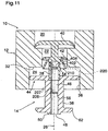
- FIG. 11 illustrates a seventh embodiment of a foam dispensing pump assembly of the invention.
- the pump assembly 10 of Figure 11 is the same as that of Figures 2 to 4 but modified so as:
- an inlet passageway 54 including an annular portion defined between the shrouding disc 404 and the stem 38 and a portion formed by the openings 402.
- Such an inlet passageway 54 has an outer opening 210 annularly about the stem 38 at the height of line 220 and inner openings 208 at the openings 402.
- Figure 11 shows that the piston 14 may be formed from two elements, an inner element including the shrouding disc 404, intermediate disc 42 and inner disc 40 and an outer element including the outer flange 44 and engagement flange 62 so as to facilitate manufacture of the shrouding disc 404.
- FIG. 12 shows an eighth embodiment in accordance with the present invention which is adapted merely for dispensing liquid from a reservoir out of the outlet 48.
- the embodiment of Figure 12 is substantially the same as the embodiment of Figure 9 , however, with a notable exception that the piston is provided slidable within a single chamber 24 of substantially constant diameter. As well, it is notable that the screen 56 is not provided.
- the pump of Figure 12 is substantially the same in its operation as pumps disclosed in U.S. Patent 5,165,577 to Ophardt, issued November 24, 1992 , the disclosure of which is incorporated herein by reference.
- the pump has, however, been modified to provide the improved inner passageway 54 in accordance with the present invention with its inner opening 208 at a height above its outer opening 210.
- Liquid in communication with outlet 48 includes liquid within the outer compartment 66, liquid within the inlet passageway 54 and liquid within the central passageway 46.
- fluid within the compartment 66 will only flow out of the outer compartment chamber 66 when the height of liquid in the outer compartment 66 is above the inner opening 208 of the inlet passageway 54.
- the inner opening 208 will be as high as possible relative to the outer compartment and Figure 12 illustrates an advantageous arrangement in which the inner opening 208 is, in fact, above the height of the disc 42.
- FIG. 12 provides some enhanced benefits.
- the embodiment of Figure 12 might be preferably advantageous for use, for example, with low viscosity fluids, such as alcohol, in which at the end of the stroke, alcohol within the central passageway 46 will readily be displaced by air and flow outwardly yet alcohol within the outer compartment 66 will not be able to flow outwardly.
- a sump is provided as the bottom of the annular outer compartment 66, defined above the outer disc 44 and with an overflow outlet provided as the inner opening 208 to the inlet passageway 54 to prevent dripping under gravity due to liquid which comes to be in the sump, whether liquid from the reservoir, or drawn back liquid or liquid from coalesced drawn back foam unless the liquid is above the height of the inner opening 208.
- inlet passageway 54 In the Figures other than Figures 6 and 7 , only one inlet passageway 54 is shown to provide communication from the outer compartment 66 to the central passageway 46.
- One or more similar inlet passageways 54 may be provided as at circumferentially spaced locations about the central axis, preferably with the inner openings 208 at the same height.
- the preferred inlet passageway 54 is shown as circular in cross-section however this is not necessary.
- the nature of the liquid to be dispensed including its viscosity and flow characteristics will be important in order for a person skilled in the art to make suitable selection of the relative sizes and dimensions and resistance to flow provided by the various passageways, inlets, outlets and screens and/or past the various discs.
- the quantity of liquid desired to be dispensed in each stroke will have a bearing on the relative proportion and sizing of the components including particularly the inner compartment 64, outer compartment 66, the axial length of a stroke of the piston, and the height of the inner opening 208 of the inlet passageway above the outer opening 210.
- the engagement disc 62 is provided on the piston 14 for engagement to move the piston inwardly and outwardly. It is to be appreciated that various other mechanisms can be provided for engagement and movement of the piston relative the body 12.
- dispensers for passing liquid and air through a screen 56 to dispense the liquid as a foam.
- the foaming screens could be replaced by another orifice device such as an atomizing nozzle of Figure 6 to produce a mist or spray.
- the preferred embodiments of the invention show the central passageway 46 and the inlet passageway 54 for dispensing of the air and/or liquid as being provided internally within a piston. Such an arrangement is believed preferred from the point of view of ease of construction of the pump assembly 10. However, it is to be appreciated that such passageways for dispensing the liquid and/or foam may be provided, in whole or in part in the body 12.
Landscapes
- Health & Medical Sciences (AREA)
- Public Health (AREA)
- Closures For Containers (AREA)
- Containers And Packaging Bodies Having A Special Means To Remove Contents (AREA)
- Reciprocating Pumps (AREA)
- Details Of Reciprocating Pumps (AREA)
Description
- This invention relates to liquid dispensers and, more particularly, piston pump liquid dispensers.
- Liquid dispensers for dispensing soaps and other fluids in liquid form are known. In some applications, it is preferable to dispense soaps and alcohol and other fluids in the form of a foam. Generally, as a foam, less soap or alcohol liquid is required to be used as, for example, for proper hand cleaning. As well, soap or alcohol as foam is less likely to run off a user's hands or other surfaces to be cleaned.
- The present inventors have appreciated the disadvantage that in many foam pumps, foam is drawn back into the pump, when the pump is left unused for a period of time, the foam which has been drawn back into the pump coalesces, that is, separates into liquid and air with the passage of time. This coalescence of foam within the pump raises a level of liquid in a chamber in the pump. Pumps in which the chamber which the coalescence takes place is open to an outlet, liquid can drip under gravity from the chamber out of the outlet.
- The present inventors have also appreciated that in many non-foaming liquid pumps the disadvantage arises that when the pump is left unused for a period of time liquid drips out of the
DocumentUS6557736B1 discloses a piston for a pump in which on the piston being moved in one direction, a disc tilts out of a coaxial sealed orientation with the chamber to assist in permitting fluid flow there past, preferably, the disc tilts by reason of the stem of the piston being deflectable on the piston being moved in the one direction. - To at least partially over come the disadvantages of known dispensers, the present invention provides an improved pumping arrangement for dispensing a fluid, preferably together with air, and reducing dripping when the dispenser is not in use.
- An object of the present invention is to provide an improved pump for dispensing liquid.
- Another object is to provide an improved pump for dispensing a liquid simultaneously with air.
- The present invention provides, according to claim 1, a piston pump assembly for liquid in which a sump is defined in a chamber into which sump liquid in the chamber flows due to gravity. A passageway leads from an outlet of the sump out of the chamber to a dispensing outlet. The dispensing outlet is at a height below the height of the sump outlet and fluid to exit the sump flows from the sump outlet upwardly in a first portion of the passageway to a height above the sump outlet then downwardly to the dispensing outlet. The chamber and its sump is defined between a piston chamber-forming member defining the chamber to be downwardly opening and a piston forming element axially slidable in the chamber. The passageway is preferably provided within the piston forming element providing communication across a sealing member disposed between the piston chamber-forming member and the piston forming element. Preferably, the dispensing outlet is provided at an outer end of the piston forming member which extends outwardly from the chamber with the dispensing outlet directed downwardly out of the chamber. In a preferred embodiment, the piston pump is adapted to have both air and fluid within the chamber and may preferably be adapted to dispense both air and fluid simultaneously to produce foam or an atomized spray.
- By reason of the passageway via which fluid is to exit the chamber extending upwardly from the sump outlet then downwardly, dripping from the dispensing outlet of the pump between cycles of dispensing can be reduced. In the preferred embodiments, dripping of liquid from the sump requires liquid to achieve a height in the sump above the height to which fluid in the passageway must be raised to flow downwardly to the dispensing outlet.
- In an embodiment of the present invention provides a piston pump for dispensing fluids including liquid from a chamber out an outlet which is at a height below a height of fluid in the chamber, and in which the chamber is always open to the outlet and the chamber is in operation to simultaneously have both liquid and air in the chamber, the improvement comprising a passageway from the chamber to the outlet, the passageway having two portions, namely a first portion extending from the outlet upwardly to an upper end and a second portion extending from the upper end downwardly to an inner end open to the chamber at a first height, and the upper end at a second height higher than the first height and at a height above a height of the outlet.
- In another embodiment of the present invention provides a piston pump assembly having a first pump comprising:
- a piston chamber forming member having a first chamber disposed about a first central axis and having a cylindrical side wall,
- an axially outer end of the first chamber being open downwardly,
- a piston forming element received in the first chamber axially slidable inwardly and outwardly therein between an outward extended position and an inward retracted position,
- the piston forming element having an axially extending stem,
- a first disc spanning radially between the stem and the first chamber side wall preventing fluid flow outwardly there past,
- a passageway through the stem providing communication from inside the first chamber outwardly past the first disc through the outer end of the first chamber,
- the passageway opening at an inner end in the first chamber and at an outer end outwardly of the first disc,
- the passageway having a first portion and a second portion,
- the first portion extending from the outer end to an upper end,
- the upper end disposed at a height above the outer end,
- the second portion extending from the upper end downwardly to the inner end,
- the inner end disposed at a height below the upper end, and
- the inner end disposed at a height above the outer end.
- Further aspects and advantages of the present invention will become apparent from the following description taken together with the accompanying drawings in which:
-
Figure 1 is a partially cut-away side view of a preferred first embodiment of a liquid dispenser with a reservoir and pump assembly in accordance with the present invention; -
Figure 2 is a partially exploded perspective view of the pump assembly shown inFigure 1 ; -
Figure 3 is a cross-sectional side view of an assembled pump assembly ofFigure 2 showing the piston in a fully retracted position; -
Figure 4 is the same side view as inFigure 3 but showing the pump in a fully extended position; -
Figure 5 is a cross-sectional side view of a pump assembly in accordance with a second embodiment of the present invention showing the piston in an extended position; -
Figure 6 is a cross-sectional side view of a pump assembly in accordance with a third embodiment of the present invention showing the piston in an extended position; -
Figure 7 is a schematic pictorial view of the piston inFigure 6 between section lines 6-6' and 7-7'; -
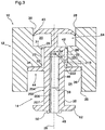
Figure 8 is a cross-sectional side view of a pump assembly in accordance with a fourth embodiment of the present invention showing the piston in an extended position in solid lines and a retracted position in dashed lines; -
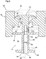
Figure 9 is a cross-sectional side view of a pump assembly in accordance with a fifth embodiment of the present invention; -
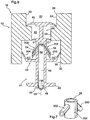
Figure 10 is a cross-sectional side view of a pump assembly in accordance with a sixth embodiment of the present invention showing the piston in an extended position in solid lines and in a retracted position in dashed lines; -
Figure 11 is a cross-sectional side view of a pump assembly in accordance with a seventh embodiment of the present invention showing the piston in an extended position; and -
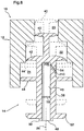
Figure 12 is a cross-sectional view of a pump assembly in accordance with an eight embodiment of the present invention. - Reference is made first to
Figures 2 ,3 and4 which show a first embodiment of a pump assembly generally indicated 10.Pump assembly 10 is best shown inFigure 2 as comprising two principal elements, a piston chamber-forming member orbody 12 and a piston forming element orpiston 14. - The piston chamber-forming
body 12 has three cylindrical portions illustrated to be of different radii, forming three chambers, aninner chamber 20, anintermediate chamber 22, and anouter chamber 24, all coaxially disposed about anaxis 26. The intermediatecylindrical chamber 22 is of the smallest radii. The outercylindrical chamber 24 is of a radius which is larger than that of the intermediatecylindrical chamber 22. The innercylindrical chamber 20 is of a radius greater than that of the intermediatecylindrical chamber 22 and, as well, is shown to be of a radius which is less than the radius of the outercylindrical chamber 24. - The
inner chamber 20 has aninlet opening 28 and anoutlet opening 29. The inner chamber has a cylindricalchamber side wall 30. The outlet opening 29 opens into an inlet end of theintermediate chamber 22 from an opening in ashoulder 31 forming an outer end of theinner chamber 20. Theintermediate chamber 22 has an inlet opening, an outlet opening 32, and a cylindricalchamber side wall 33. Theoutlet opening 32 of theintermediate chamber 22 opens into an inlet end of theouter chamber 24 from an opening in ashoulder 34 forming the inner end of theouter chamber 24. Theouter chamber 24 has an inlet opening, outlet opening 35 and a cylindricalchamber side wall 36. -
Piston 14 is axially slidably received in thebody 12. Thepiston 14 has anelongate stem 38 upon which four discs are provided at axially spaced locations. Aninner flexing disc 40 is provided at an innermost end spaced axially from anintermediate flexing disc 42 which, in turn, is spaced axially from anouter sealing disc 44. Theinner disc 40 is adapted to be axially slidable within theinner chamber 20. Theintermediate disc 42 is adapted to be axially slidable within theintermediate chamber 22. - The
intermediate disc 42 has a resilient peripheral edge which is directed outwardly and adapted to prevent fluid flow inwardly yet to deflect to permit fluid flow outwardly therepast. Similarly, theinner disc 40 has a resilient outer peripheral edge which is directed outwardly and is adapted to prevent fluid flow inwardly yet to deflect to permit fluid flow outwardly therepast. - The
outer sealing disc 44 is adapted to be axially slidable within the outercylindrical chamber 24. Theouter sealing disc 44 extends radially outwardly from thestem 38 to sealably engage theside wall 36 of theouter chamber 24, and prevent flow therepast either inwardly or outwardly. - The
piston 14 essentially forms, as defined between theinner disc 40 and theintermediate disc 42, an annularinner compartment 64 which opens radially outwardly as an annular opening between thediscs piston 14 effectively forms between theintermediate sealing disc 42 and theouter sealing disc 44 an annularouter compartment 66 which opens radially outwardly as an annular opening between thediscs - The
stem 38 has an outermost hollowtubular portion 202 with acylindrical side wall 204 generally coaxially about thecentral axis 26 defining acentral passageway 46 within thetubular portion 202. Thecentral passageway 46 extends from anoutlet 48 at theoutermost end 50 of thestem 38 centrally through thestem 38 to a closedinner end 52. - The
cylindrical side wall 204 of the hollowtubular portion 202 of thestem 38 extends radially of thecentral axis 26 from an innerside wall surface 206 to an outerside wall surface 207. Aninlet passageway 54 provides communication through thestem 38 into thecentral passageway 46. Theinlet passageway 54 extends through thecylindrical side wall 204 from aninner opening 208 in the innerside wall surface 206 to anouter opening 210 in the outerside wall surface 207. Theinlet passageway 54 has itsoutlet opening 210 located on thestem 38 in between theouter disc 44 and theintermediate disc 42. Theinlet passageway 54 in extending from theinner opening 208 to theouter opening 210 radially outwardly and axially outwardly so as to provide the inlet opening 210 located on thestem 38 axially inwardly from theoutlet opening 210. Theinlet passageway 54 extends about an inlet axis extending in a flat plane including thecentral axis 26 and with the inlet axis in that flat plane extending at an angle to thecentral axis 26 as the inlet axis 214 extends radially outwardly and axially outwardly. Theinlet passageway 54 is axially circular in any cross-section about its inlet axis 214. - The
inlet passageway 54 has its an outermost portion of itsinner opening 208 at a height indicated by dashedhorizontal line 218. For fluid in the annularouter compartment 66 to flow under gravity into thecentral passageway 46 fluid in the annularouter compartment 66 must be at a height above the height ofline 218. - The
inlet passageway 54 has an axially outermost portion of itsouter opening 210 at a height indicated by dashedhorizontal line 222 and an axially innermost portion of itsouter opening 210 at a height indicated by dashedhorizontal line 220. As shown, theline 218 is at a height vertically above the height of theline 220 and theline 222 that is axially inward as shown. - Communication is provided between the
outlet 48 and theouter opening 210 via a continuous passageway formed by a first portion consisting of thecentral passageway 46 between theoutlet 48 and theinner opening 208 and a second portion consisting of theinlet passageway 54 between theinner opening 208 and theouter opening 210. As seen, theinner opening 208 is an upper end of this first portion whichinner opening 208 is at a height above theoutlet 48 forming an outer end of this first portion. As well, theouter opening 210 forming an inner end of the continuous passageway is disposed at a height below theinner opening 208. Theouter end 210 is also disposed at a height above theoutlet 48. - A
foam inducing screen 56 is provided in thecentral passageway 46 intermediate between theinner opening 208 and theoutlet 48. Thescreen 56 may be fabricated of plastic, wire or cloth material. It may comprise a porous ceramic measure. Thescreen 56 provides small apertures through which an air and liquid mixture may be passed to aid foam production as by production of turbulent flow through small pores or apertures of the screen thereof in a known manner. - The
piston 14 carries an engagement flange ordisc 62 on thestem 38 outward from theouter sealing disc 44. Theengagement disc 62 is provided for engagement by an activating device in order to move thepiston 14 in and out of thebody 12. - In a withdrawal stroke with movement from the retracted position of
Figure 3 to the extended position ofFigure 4 , the volume between theinner disc 40 and theintermediate disc 42 decreases such that fluid is displaced outwardly past theintermediate disc 42 to between theintermediate disc 42 and theouter disc 44. At the same time, the volume in the annularouter compartment 66 between theintermediate disc 42 and theouter disc 44 increases, with such increase being greater than the volume decrease in the annularinner compartment 64 between theinner disc 40 and theintermediate disc 42 such that in addition to the fluid displaced outwardly pastintermediate disc 42, what is referred to herein as inhaled material namely air, liquid and/or foam is drawn inwardly via theoutlet 48,central passageway 46, and theinlet passageway 54 into the annularouter compartment 66 between theintermediate disc 42 and theouter disc 44. - In a retraction stroke from the position of
Figure 4 to the position ofFigure 3 , the volume in the annularouter compartment 66 between theintermediate disc 42 and theouter disc 44 decreases such that what is referred to herein as exhaled material namely air, liquid and/or foam in the annularouter compartment 66 and in thecentral passageway 46 above thescreen 56 is forced under pressure out through thescreen 56. Air and liquid simultaneously passing through thescreen 56 is mixed and commingled producing foam which is discharged out theoutlet 48. At the same time, in the retraction stroke, the volume in the annularouter compartment 66 between theinner disc 40 and theintermediate disc 42 increases drawing liquid from inside the fluid containing reservoir or container past theinner disc 40. - Reciprocal movement of the
piston 14 between the retracted and extended positions will successively draw and pump precise amounts of liquid from the container and mix such liquid with air from the atmosphere and dispense the liquid commingled with the air as a foam. - In a typical withdrawal stroke, the inhaled material includes material in the
inlet passageway 54 and thecentral passageway 46, whether inwardly or outwardly of thescreen 56, at the end of the last retraction stroke. Such material may typically include foam which substantially fills thecentral passageway 46 outward of the screen, and foam, liquid and/or air in thecentral passageway 46 inwardly of thescreen 56 and foam, liquid and/or air in theinlet passageway 54. Drawback of such inhaled materials, particularly drawback through thescreen 56, or through the smallerdiameter inlet passageway 54, may result in additional foam being produced. - The annular
outer compartment 66 is, in effect, a closed bottom compartment forming a sump whose bottom is defined by theouter disc 44, sides are defined by theside wall 36 and the innerside wall surface 206 of thestem 38 and with an overflow outlet defined by theinner opening 208 of theinlet passageway 54. The lowermost portion ofinner opening 208 of theinlet passageway 54 is at a constant height indicated byline 218 above theouter disc 44, and this height together with the difference in radius of theside wall 36 and the innerside wall surface 206 of thestem 38 define a sump volume being the volume of liquid which may be retained within the annularouter compartment 66 above theouter disc 44 against over flow out theinlet passageway 54 to thecentral passageway 46. - In a retraction stroke, the material in the annular
outer compartment 66 is forced out of theouter compartment 66 via theouter opening 210 of theinlet passageway 54. In the retraction stroke, the expelled material includes air and due to a venturi effect, the air being expelled through theouter opening 210 of theinlet passageway 54 entrains liquid and foam in the sump in the annularouter compartment 66 and draws the level of material in the sump down typically to the height indicated byline 222, or at least to a height between theline 220 and theline 222. Subsequently, in the next withdrawal stroke, the inhaled material is drawn into the annularouter compartment 66 via theinlet passageway 54 and, simultaneously, a next allotment of liquid from the annularinner compartment 64 is forced from the annularinner compartment 64 past theintermediate disc 42 into the annularouter compartment 66. The inhaled material and the allotment of liquid come to sit in the sump with the liquid at the bottom of the sump, the foam above the liquid and air above the foam. With the passage of time, foam in the sump will tend to coalesce, that is, separate into air and liquid, with such coalesced liquid increasing the level of liquid in the sump. In so far as the level of liquid in the sump is below theline 218 liquid will not flow due to gravity from theouter compartment 66 into thecentral passageway 46. The volume of liquid which may come to settle in the bottom of the sump without over flow from the sump via theinlet passageway 54 is represented by the difference in heights of theouter opening 210 and theinner opening 208, more particularly, at least the difference in height betweenline 220 andline 218 and, more typically, the difference in height between theline inner opening 208 above theouter opening 210 and increasing the radius of the sump can increase the volume which can be accommodated in the sump before over flow from the sump will occur. - In contract with a prior art arrangement in the
inlet passageway 54 extends merely radially horizontally providing the equivalent of the inner opening and the outer opening of the inlet passageway at the same height, the arrangement of the present invention with theinner opening 208 at a height above theouter opening 210 reduces the tendency of the pump to drip between strokes. - Operation of the pump assembly illustrated in
Figures 2 to 4 will draw liquid out of a container creating a vacuum therein. The pump assembly is preferably adapted for use with a collapsible container. Alternatively, a suitable vent mechanism may be provided if desired as, for example, for use in a non-collapsible container to permit atmospheric air to enter the container and prevent a vacuum being built up therein. - Both the
piston 14 and thebody 12 may be formed as unitary elements or from a minimal number of elements from plastic as by injection molding. - Reference is now made to
Figure 1 which shows a liquid soap dispenser generally indicated 70 utilizing thepump assembly 10 ofFigures 2 to 4 secured in theneck 58 of a sealed, collapsible container orreservoir 60 containingliquid hand soap 68 to be dispensed.Dispenser 70 has a housing generally indicated 78 to receive and support thepump assembly 10 and thereservoir 60.Housing 78 is shown with aback plate 80 for mounting the housing, for example, to abuilding wall 82. Abottom support plate 84 extends forwardly from the back plate to support and receive thereservoir 60 and pumpassembly 10. As shown,bottom support plate 84 has acircular opening 86 therethrough. Thereservoir 60 sits supported onshoulder 79 of thesupport plate 84 with theneck 58 of thereservoir 60 extending throughopening 86 and secured in the opening as by a friction fit, clamping and the like. Acover member 85 is hinged to an upperforward extension 87 of theback plate 80 so as to permit replacement ofreservoir 60 and itspump assembly 10. -
Support plate 84 carries at a forward portion thereof anactuating lever 88 journalled for pivoting about a horizontal axis at 90. An upper end of thelever 88 carries ahook 94 to engageengagement disc 62 andcouple lever 88 topiston 14, such that movement of thelower handle end 96 oflever 88 from the dashed line position to the solid line position, in the direction indicated byarrow 98slides piston 14 inwardly in a retraction pumping stroke as indicated byarrow 100. On release of thelower handle end 96,spring 102 biases the upper portion oflever 88 downwardly so that the lever drawspiston 14 outwardly to a fully withdrawn position as seen in dashed lines inFigure 1 .Lever 88 and itsinner hook 94 are adapted to permit manual coupling and uncoupling of thehook 94 as is necessary to remove and replacereservoir 60 and pumpassembly 10. Other mechanisms for moving the piston can be provided including mechanized and motorized mechanisms. - In use of the
dispenser 70, once exhausted, the empty, collapsedreservoir 60 together with the attachedpump 10 are removed and anew reservoir 60 and attachedpump 10 may be inserted into the housing. Preferably, the removedreservoir 60 with its attachedpump 10 are both made entirely out of recyclable plastic material which can easily be recycled without the need for disassembly prior to cutting and shredding. - It is to be appreciated that in the first embodiment of
Figures 2 to 4 , theinner disc 40 and theintermediate disc 42 form a first stepped pump and, similarly, theintermediate disc 42 and theouter disc 44 form a second stepped pump. The first pump and second pump are out of phase in the sense that in any one retraction or extension stroke while one pump is drawing fluid in, the other is discharging fluid out. This is not necessary in accordance with the present invention. - The present invention preferably requires a sump in which fluid will accumulate and in which an overflow outlet, for example, the
inner opening 208 inFigure 3 , is at a height higher than the level to which fluid in the sump is drawn down to between strokes, such that any coalescence of foam or flow down of liquid in the sump between strokes which will result in the level of liquid in the sump increasing may be better accommodated before dripping from the sump may occur. - Reference is made to
Figure 5 which shows a second embodiment of the present invention with thepiston 14 in an extended position in solid lines and in a retracted position in dashed lines. Thepump assembly 10 ofFigure 5 is the same as that ofFigures 2 to 4 but modified to remove theintermediate disc 42 from thepiston 14 and to provide an equivalent flexible annular intermediate disc orflange 142 to extend inwardly from thebody 12 within theintermediate chamber 22. In this regard, thepiston 14 has itsstem 38 to be of a substantially constant diameter over portions of the outer wall of thestem 38 which theflange 142 is to engage. The piston is shown to be constructed of two parts, aninner portion 43 carrying theinner disc 42 and anouter portion 45 carrying theouter disc 44 as can be advantageous not only for assembly in place in thebody 12 but also for ease of making thepassageway inlet 54. Thecentral passageway 46 is shown to have a reduced diameter innermost portion to better accommodate theinlet passageway 54. - Reference is made to
Figures 6 and 7 which show a third embodiment of the invention which is similar in function to the embodiment illustrated inFigure 2 with similar reference numerals used to refer to similar elements. The embodiment ofFigures 6 and 7 differs in a number of features. - Firstly, the embodiment of
Figure 6 has twoinlet passageways 54 each provided at diametrically opposed locations about thestem 38 and each within abranch tubular member 302 extending from the centraltubular portion 202 of thestem 38 radially outwardly and axially outwardly. Eachbranch tube 302 defines theinlet passageway 54 therein from theouter opening 210 at a distal end of eachbranch tubular member 302 to theinner opening 208 where the hollow interior of the branch tubular member opens into thecentral passageway 54. As shown, the cross-sectional area of theinlet passageway 54 preferably reduces from theouter opening 210 to theinner opening 208 although this is not necessary. -
Figure 6 also differs from the embodiment ofFigure 2 in that theouter disc 44 is provided with an inwardly extending annularlyouter periphery 304 of reduced diameter for engaging theside wall 36 of theouter chamber 24 to substantially prevent fluid flow in the outer chamber past theouter disc 44 in an outward direction but which may be elastically deformable to permit fluid flow of some air in an inward direction inwardly past theouter disc 44 in a withdrawal stroke. - The embodiment of
Figure 6 further differs from the embodiment ofFigure 2 in that thefoam producing screen 56 has been eliminated and replaced by anozzle member 156 disposed proximate theoutlet 48 to at least partially atomized fluid when fluid and air pass therethrough simultaneously.Nozzle member 156 is shown to always be open to provide communication between the atmosphere and thecentral passageway 46. -
Figures 2 to 4 illustrate a first embodiment of the invention in which theinner chamber 20 is of a greater diameter than theintermediate chamber 22 and theintermediate chamber 22 is of a greater diameter than theouter chamber 24. Reference is now made toFigure 8 which illustrates a third embodiment of a foam dispensing pump assembly of the invention in which theinner chamber 20 is of a smaller diameter than theintermediate chamber 22 and theintermediate chamber 22 is of a smaller diameter than theouter chamber 24. The piston illustrated inFigure 8 has components identical to the components illustrated inFigures 2 to 4 , however, with a notable difference that theinner disc 40 is smaller than theintermediate disc 42. InFigure 8 , theinner disc 40 and theintermediate disc 42 form a first stepped pump and theintermediate disc 42 an theouter disc 44 form a second stepped pump. The two stepped pumps are in phase in a sense that both operate to discharge fluid outwardly on a retraction stroke and to draw fluid in between their respective discs on an extension stroke. In an extension stroke, the inner pump effectively serves to draw liquid from the reservoir and between theinner disc 40 and theintermediate disc 42 and to discharge it past theintermediate disc 42 between theintermediate disc 42 and theouter disc 44. The second pump serves to draw air inwardly into between theintermediate disc 42 and theouter disc 44 in a withdrawal stroke and to discharge liquid and air outwardly through theoutlet 48 in a retraction stroke. As in the case of the first embodiment, theinlet passageway 54 has itsinner opening 208 at a height above itsouter opening 210. - In
Figures 2 to 4 , in effect, a one-way valve mechanism for one-way flow outwardly from the reservoir to thechamber 42 is provided by theinner disc 40 in an inner chamber. Reference is made toFigure 9 which shows a fourth embodiment of the foam dispensing pump assembly of the invention in which theouter chamber 24 is larger thanchamber 42 intermediately inwardly therefrom. A one-way valve 150 is provided in aninlet port 152 to thechamber 42.Valve 150 has astem 154 which carries aninner valve disc 156 which extends radially outwardly from thestem 154 to engage the side wall of thechamber 42. Thevalve disc 156 has a resilient outer perimeter which is directed outwardly and engages thechamber 42 to prevent fluid flow therepast inwardly yet deflects radially inwardly to prevent fluid flow outwardly therepast. Similar such one-way valves could be used in replacement of theinner disc 40 in the embodiments ofFigures 2 ,6 and8 . - Reference is made to
Figure 10 which illustrates a fifth embodiment for use with a non-collapsible bottle in that in each stroke, some quantity of air is permitted to pass firstly when the pump is in the extended position from between theouter disc 44 and theintermediate disc 42 inwardly past theintermediate disc 42 and, subsequently, when the piston is in the retracted position to pass from between theintermediate disc 42 and theinner disc 40 to past theinner disc 40 and into the reservoir. Relative selection of when each of thediscs inner disc 40 and theintermediate disc 42 are in engagement with their respective chamber to prevent fluid flow outwardly. InFigure 10 , the piston is shown in solid lines in a preferred fully extended position and in dashed lines in a preferred fully retracted position. The pump ofFigure 10 is of the type disclosed inU.S. Patent 6,409,050 issued June 25, 2002 , the disclosure of which is incorporated herein by reference. The pump ofFigure 10 , however, differs from the pumps ofU.S. Patent 6,409,050 insofar as being modified to provide theadvantageous inlet passageway 54 in accordance with the present invention with itsinner opening 208 at a height above itsouter opening 210. - The pump of
Figure 10 may be modified to avoid thefoaming screen 56, in which case the pump may be used without an intention to produce foam and need not have a capability of foaming. Liquid in theouter chamber 66 will tend to settle the lower portion of theouter chamber 66 on top of theouter disc 44, and will tend to be expelled out ofpassageway 54 via thelower opening 210 before air in theouter chamber 66 above the liquid. After expelling the liquid, air in theouter chamber 66 will then be expelled tending to clear theinlet passageway 54 as well as thecentral passageway 46 of liquid. Provision of a plurality ofinlet passageways 54 circumferentially about thestem 38 withopenings 210 at the same height can assist in expelling liquid before air is expelled, enhancing the self cleaning capability. - The relative volumes of the liquid permitted to be displaced in a metered-like manner downwardly from the reservoir between the
discs outer chamber 66 may be relatively selected towards, on one hand, drawing in only as much air as is needed to replace in the reservoir the liquid drawn out in a stroke and, on the other hand, drawing in air sufficient to help urging all of the fluid out of theinlet passageway 54 and thecentral passageway 46. - Reference is now made to
Figure 11 which illustrates a seventh embodiment of a foam dispensing pump assembly of the invention. Thepump assembly 10 ofFigure 11 is the same as that ofFigures 2 to 4 but modified so as: - (a) to reduce the outer diameter of the
stem 38 between thedisc - (b) to provide a pair of
openings 402 through the stem at effectively the same axial location as theinner openings 208; - (c) to provide an
annular shrouding disc 404 which is secured at a radically inner end axially inward of theopenings 402 and extends radially outwardly and axially outwardly to an outer end 406 disposed at a height indicated by dashedhorizontal line 220 below theinner openings 208. - As a result, an
inlet passageway 54 is provided including an annular portion defined between theshrouding disc 404 and thestem 38 and a portion formed by theopenings 402. Such aninlet passageway 54 has anouter opening 210 annularly about thestem 38 at the height ofline 220 andinner openings 208 at theopenings 402.Figure 11 shows that thepiston 14 may be formed from two elements, an inner element including theshrouding disc 404,intermediate disc 42 andinner disc 40 and an outer element including theouter flange 44 andengagement flange 62 so as to facilitate manufacture of theshrouding disc 404. - Each of the pumps of
Figures 2 to 10 is adapted for simultaneously dispensing liquid and air out of theoutlet 48. Reference is made toFigure 12 which shows an eighth embodiment in accordance with the present invention which is adapted merely for dispensing liquid from a reservoir out of theoutlet 48. The embodiment ofFigure 12 is substantially the same as the embodiment ofFigure 9 , however, with a notable exception that the piston is provided slidable within asingle chamber 24 of substantially constant diameter. As well, it is notable that thescreen 56 is not provided. The pump ofFigure 12 is substantially the same in its operation as pumps disclosed inU.S. Patent 5,165,577 to Ophardt, issued November 24, 1992 , the disclosure of which is incorporated herein by reference. The pump has, however, been modified to provide the improvedinner passageway 54 in accordance with the present invention with itsinner opening 208 at a height above itsouter opening 210. - When a pump of the type shown in
Figure 12 is left inactive after use, there is a tendency of fluid to drip out of theoutlet 48 as by air moving up through theoutlet 48 to attempt to displace liquid. Liquid in communication withoutlet 48 includes liquid within theouter compartment 66, liquid within theinlet passageway 54 and liquid within thecentral passageway 46. With the arrangement inFigure 12 , at the least, fluid within thecompartment 66 will only flow out of theouter compartment chamber 66 when the height of liquid in theouter compartment 66 is above theinner opening 208 of theinlet passageway 54. Preferably, therefore, theinner opening 208 will be as high as possible relative to the outer compartment andFigure 12 illustrates an advantageous arrangement in which theinner opening 208 is, in fact, above the height of thedisc 42. Of course, providing theinner opening 208 at least some height above theouter opening 210 provides some enhanced benefits. The embodiment ofFigure 12 might be preferably advantageous for use, for example, with low viscosity fluids, such as alcohol, in which at the end of the stroke, alcohol within thecentral passageway 46 will readily be displaced by air and flow outwardly yet alcohol within theouter compartment 66 will not be able to flow outwardly. - In each of the embodiments of
Figures 2 to 12 , a sump is provided as the bottom of the annularouter compartment 66, defined above theouter disc 44 and with an overflow outlet provided as theinner opening 208 to theinlet passageway 54 to prevent dripping under gravity due to liquid which comes to be in the sump, whether liquid from the reservoir, or drawn back liquid or liquid from coalesced drawn back foam unless the liquid is above the height of theinner opening 208. - In the Figures other than
Figures 6 and 7 , only oneinlet passageway 54 is shown to provide communication from theouter compartment 66 to thecentral passageway 46. One or moresimilar inlet passageways 54 may be provided as at circumferentially spaced locations about the central axis, preferably with theinner openings 208 at the same height. Thepreferred inlet passageway 54 is shown as circular in cross-section however this is not necessary. - It is to be appreciated that the nature of the liquid to be dispensed including its viscosity and flow characteristics will be important in order for a person skilled in the art to make suitable selection of the relative sizes and dimensions and resistance to flow provided by the various passageways, inlets, outlets and screens and/or past the various discs. As well, the quantity of liquid desired to be dispensed in each stroke will have a bearing on the relative proportion and sizing of the components including particularly the
inner compartment 64,outer compartment 66, the axial length of a stroke of the piston, and the height of theinner opening 208 of the inlet passageway above theouter opening 210. - In the preferred embodiments, the
engagement disc 62 is provided on thepiston 14 for engagement to move the piston inwardly and outwardly. It is to be appreciated that various other mechanisms can be provided for engagement and movement of the piston relative thebody 12. - Most of the preferred embodiments show dispensers for passing liquid and air through a
screen 56 to dispense the liquid as a foam. The foaming screens could be replaced by another orifice device such as an atomizing nozzle ofFigure 6 to produce a mist or spray. - The preferred embodiments of the invention show the
central passageway 46 and theinlet passageway 54 for dispensing of the air and/or liquid as being provided internally within a piston. Such an arrangement is believed preferred from the point of view of ease of construction of thepump assembly 10. However, it is to be appreciated that such passageways for dispensing the liquid and/or foam may be provided, in whole or in part in thebody 12. - While this invention has been described with reference to preferred embodiments, the invention is not so limited. Many modifications and variations will now occur to persons skilled in the art. For a definition of the invention, reference is made to the appended claims.
Claims (15)
- A piston pump assembly having a first pump comprising:a piston chamber forming member (12) having a first chamber (24) disposed about a first central axis (26) and having a cylindrical side wall (36),an axially outer end (35) of the first chamber (24) being open downwardly,a piston forming element (14) received in the first chamber (24) axially slidable inwardly and outwardly therein between an outward extended position and an inward retracted position,the piston forming element (14) having an axially extending stem (38),a first disc (44) spanning radially between the stem (38) and the first chamber side wall (36) preventing fluid flow outwardly therepast,a continuous passageway (46,54) through the stem (38) providing communication from inside the first chamber (24) outwardly past the first disc (44) through the outer end (35) of the first chamber (24),the continuous passageway (46,54) opening at an outer opening (210), which is open to the first chamber (24) and at an outlet (48) outwardly of the first disc (44),wherein:the first chamber (24) in normal use during or after operation to dispense fluid from the outlet (48) including reciprocal sliding of the piston forming element (14) relative the piston chamber forming member (12) both air from the atmosphere and a liquid from a liquid reservoir (60) become simultaneously disposed in the first chamber (24),the piston pump assembly including a foam generator (56) disposed in the continuous passageway comprising a porous member for generating turbulence in fluid passing there through to generate foam when the air and the liquid pass there through simultaneously, andthe piston pump assembly includes a liquid pump for providing the liquid from the reservoir (60) via a liquid outlet into the first chamber (24),the liquid capable of foaming, and in operation of the first pump, fluid including foam between the first chamber (24) and the outlet (48) is drawn back into the first chamber (24) via the continuous passageway (46, 54), andin normal use during or after operation to dispense fluid from the outlet (48) including reciprocal sliding of the piston forming element (14) relative the piston chamber forming member (12):the continuous passageway (46,54) having as a first portion a central passageway (46) and as a second portion an inlet passageway (54),the central passageway (46) extending from the outlet (48) to an inner opening (208),(a) the inner opening (208) disposed at a height above the outlet (48),(b) the inlet passageway (54) extending from the inner opening (208) open into the central passageway (46) downwardly to the outer opening (210),(c) the outer opening (210) disposed at a height below the inner opening (208), and(d) the outer opening (210) disposed at a height above the outlet (48).
- A piston pump assembly as claimed in claim 1 wherein:the stem (38) comprises a generally cylindrical central tubular member (202) about the first central axis (26) defining the central passageway (46) of the continuous passageway(46,54) therein with the outlet (48) of the passageway (46,54) at an outermost end (50) of the central tubular member (202),the central tubular member (202) carrying a branch tubular member (302) extending from the central tubular member (202) radially outwardly and axially outwardly,the branch tubular member (302) defining the inlet passageway (54) therein with the outer opening (210) at an outermost end of the branch tubular member (302).
- A piston pump assembly as claimed in claim 1 or 2 wherein the first disc (44) is carried on the stem (38) and extends radially outwardly from the stem (38) for engagement with the first chamber side wall (36) to prevent fluid flow outwardly therepast.
- A piston pump assembly as claimed in any one of claims 1, 2 or 3 wherein:
in reciprocal sliding of the piston forming element (14) in the first chamber (24) in a cycle of operation including an inward stroke from the extended position to the retracted position and an outward stroke from the retracted position to the outward position, in one of the inward stroke and outward stroke fluid in the first chamber (24) is displaced from inside the first chamber (24) through the continuous passageway (46,54) to exit via the outlet (48), and in the other of the inward stroke and outward stroke fluid is drawn through the outlet (48) into the first chamber (24) via the continuous passageway(46,54). - A piston pump assembly as claimed in any one of claims 1 to 4 wherein:
the liquid pump having a liquid outlet one way valve (42,142) across the liquid outlet permitting flow outwardly and preventing flow inwardly. - A piston pump assembly as claimed in any one of claims 1 to 4 wherein:the liquid pump is defined by the piston chamber forming member (12) having a liquid chamber (22) and with the piston forming element (14) having a liquid disc (42) received in the liquid chamber (22),the liquid chamber (22) disposed about the central axis (26) and having a cylindrical liquid chamber side wall (33),the liquid chamber (22) having a liquid chamber inlet (29) opening into the liquid chamber (22) in communication with liquid from the liquid reservoir (60),a liquid chamber inlet one way valve (40,150) across the liquid chamber inlet permitting liquid flow there through outwardly into the liquid chamber (22),the liquid outlet comprising an outlet from the liquid chamber (22),a liquid disc (42) received in the liquid chamber (22) axially between the liquid chamber inlet (29) and the liquid outlet, the liquid disc (42) axially slidable with the piston forming element (14) inwardly and outwardly in the liquid chamber (22),the liquid disc (42) extending radially outwardly for engagement with the liquid chamber side wall (33) to prevent fluid flow outwardly therepast,wherein in reciprocal sliding of the liquid disc (42) of the piston forming element (14) axially inwardly and outwardly in the liquid chamber (22) in one stroke liquid is drawn from the liquid reservoir (60) through the liquid chamber inlet (29) into the liquid chamber (22) and, in an opposite stroke, liquid in the liquid chamber (22) is displaced from inside the liquid chamber (22) out through the liquid outlet,in reciprocal sliding of the liquid disc (42) of the piston forming element (14) axially inwardly and outwardly in the liquid chamber (22) in a cycle of operation (a) in a first of the inward stroke and the outward stroke simultaneously (i) fluid in the first chamber (24) is displaced from inside the first chamber (24) through the continous passageway (46,54) to exit via the outlet (48), and (ii) liquid is drawn from the liquid reservoir (60) through the liquid inlet into the liquid chamber (22), and (b) in an opposite second of the inward stroke and outward stroke simultaneously (i) fluid is drawn through the outlet (48) into the first chamber (24) via the continuous passageway (46,54) and (ii) liquid in the liquid chamber (22) is displaced from inside the liquid chamber (22) out through the liquid outlet.
- A piston pump assembly as claimed in claim 6 wherein one or both of the first chamber (24) and the liquid chamber (22) comprises a stepped cylinder.
- A piston pump assembly as claimed in any one of claims 4 to 7 wherein the first pump and liquid pump are out of phase with, in reciprocal sliding of the piston forming element (14) axially inwardly and outwardly in a cycle of operation, (a) in a first of the inward stroke and the outward stroke simultaneously (i) fluid comprising air and liquid in the first chamber (24) is displaced from inside the first chamber (24) through the continuous passageway(46,54) to exit via the outlet (48), and (ii) liquid is drawn from the liquid reservoir (60) through the liquid chamber inlet (29) into the liquid chamber (22), and (b) in an opposite, second of the inward stroke and the outward stroke simultaneously (i) fluid comprising air and liquid is drawn through the outlet (48) into the first chamber (24) via the continuous passageway(46,54), and (ii) liquid in the liquid chamber (22) is displaced from inside the liquid chamber (22) out through the liquid outlet.
- A piston pump assembly as claimed in any one of claims 4 to 7 wherein the first pump and liquid pump are in phase with, in reciprocal sliding of the piston forming element (14) axially inwardly and outwardly in a cycle of operation, (a) in a first of the inward stroke and the outward stroke simultaneously (i) fluid comprising air and liquid in the first chamber (24) is displaced from inside the first chamber (24) through the continuous passageway (46,54) to exit via the outlet end (48), and (ii) liquid in the liquid chamber (22) is displaced from inside the liquid chamber (22) out through the liquid outlet, and (b) in an opposite, second of the inward stroke and the outward stroke simultaneously (i) fluid comprising air and liquid is drawn through the outlet (48) into the first chamber (24) via the continuous passageway(46,54), and (ii) liquid is drawn from the liquid reservoir (60) through the liquid chamber inlet into the liquid chamber (22).
- A piston pump assembly as claimed in any one of claims 1 to 9 wherein the outlet (48) is at a height below a height of fluid in the first chamber (24), the first chamber (24) is always open to the outlet (48), and the first chamber (24) is in operation to simultaneously have both liquid and air in the first chamber (24).
- A piston pump assembly as claimed in any one of claims 1 to 10 wherein in operation of the first pump, fluid between the first chamber (24) and the outlet (48) is drawn back into the first chamber (24) via the continuous passageway(46,54).
- A piston pump assembly as claimed in any one of claims 1 to 11 wherein the first pump is adapted to dispense from the outlet (48) the liquid admixed with air as foam and in operation of the first pump fluid including foam between the first chamber (24) and the outlet (48) is drawn back into the first chamber (24) via the continuous passageway(46,54).
- A piston pump assembly as claimed in any one of claims 1 to 12 wherein the first chamber (24) and continuous passageway(46,54) form a sump into which liquid in the first chamber (24) will flow due to gravity with a sump volume being a volume of fluid which can be accommodated in the sump without overflow out the continuous passageway (46, 54) to the outlet (48) due to gravity being defined by the cumulative volume in the first chamber (24) and in the continuous passageway (46,54) below the inner opening (208).
- A piston pump assembly as claimed in claim 13 in which the first chamber (24) has a chamber volume sufficient to accommodate any fluid in the first chamber (24) at the end of the draw back, plus any foam drawn back into the first chamber (24) via the continuous passageway(46,54) from between the first chamber (24) and the outlet (48), and with the sump volume being at least equal to the liquid in the first chamber (24) at the end of the draw back plus liquid resulting if all foam drawn back into the first chamber was to coalesce into liquid.
- A piston pump assembly as claimed in any one of claims 1 to 14, wherein the inlet passageway (54) extends about an inlet axis extending in a flat plane including the central axis (26) and in the flat plane at an angle to the central axis (26) as the inlet axis extends radially outwardly and axially outwardly.
Applications Claiming Priority (1)
| Application Number | Priority Date | Filing Date | Title |
|---|---|---|---|
| CA2613785A CA2613785C (en) | 2007-12-07 | 2007-12-07 | Angled slot foam dispenser |
Publications (3)
| Publication Number | Publication Date |
|---|---|
| EP2067426A2 EP2067426A2 (en) | 2009-06-10 |
| EP2067426A3 EP2067426A3 (en) | 2017-11-01 |
| EP2067426B1 true EP2067426B1 (en) | 2020-05-06 |
Family
ID=40276127
Family Applications (1)
| Application Number | Title | Priority Date | Filing Date |
|---|---|---|---|
| EP08021222.8A Active EP2067426B1 (en) | 2007-12-07 | 2008-12-05 | Angled slot foam dispenser |
Country Status (4)
| Country | Link |
|---|---|
| US (1) | US8272539B2 (en) |
| EP (1) | EP2067426B1 (en) |
| CN (1) | CN101449940B (en) |
| CA (2) | CA2875087C (en) |
Cited By (1)
| Publication number | Priority date | Publication date | Assignee | Title |
|---|---|---|---|---|
| RU216794U1 (en) * | 2022-12-01 | 2023-03-01 | Евгений Александрович Непокульчицкий | REPLACEMENT CONTAINER FOR DISPENSING DEVICE |
Families Citing this family (54)
| Publication number | Priority date | Publication date | Assignee | Title |
|---|---|---|---|---|
| US8672187B2 (en) * | 2009-02-27 | 2014-03-18 | Gotohti.Com Inc. | Method and apparatus for generating ozone containing fluid and foam |
| US8733596B2 (en) | 2009-02-27 | 2014-05-27 | Gotohti.Com Inc. | Ozone foam dispenser |
| CA2967107C (en) | 2009-02-27 | 2020-04-21 | Heiner Ophardt | Manual fluid dispenser with electrical generator |
| US8201707B2 (en) | 2009-02-27 | 2012-06-19 | Gotohti.Com Inc | Manual fluid dispenser with discharge measurement |
| CA2672057C (en) * | 2009-07-14 | 2017-07-11 | Gotohti.Com Inc. | Draw back push pump |
| CA2680993C (en) * | 2009-10-02 | 2016-03-29 | Gotohti.Com Inc. | Convertible peristaltic and piston pump dispenser |
| CA2687879C (en) | 2009-12-08 | 2016-11-01 | Gotohti.Com Inc. | Piston with frangible piston stop |
| EP2363539B1 (en) * | 2010-03-01 | 2012-05-23 | Urs Sträuli | Device and method for use in bodily hygiene, in particular showering, bathing or washing hands |
| CA2698915C (en) | 2010-04-01 | 2017-06-27 | Gotohti.Com Inc. | Stationary stem pump |
| CA2722646C (en) | 2010-11-26 | 2018-01-02 | Gotohti.Com Inc. | Air assisted severance of viscous fluid stream |
| CA2772507C (en) | 2012-03-20 | 2018-12-18 | Gotohti.Com Inc. | Adaptive preload pump |
| CA2776684C (en) | 2012-05-11 | 2019-07-23 | Gotohti.Com Inc. | Ozone foam dispenser |
| US9175674B2 (en) | 2012-06-19 | 2015-11-03 | Gotohti.Com Inc. | Drawback check valve |
| US20140124540A1 (en) * | 2012-11-07 | 2014-05-08 | Gojo Industries, Inc. | Under-counter mount foam dispensing systems with permanent air compressors and refill units for same |
| DE102013009795A1 (en) * | 2013-06-12 | 2014-12-18 | Stephan Krüger | Device for filling watering cans |
| US9648992B2 (en) | 2013-12-19 | 2017-05-16 | Gojo Industries, Inc. | Pumps with vents to vent inverted containers and refill units having non-collapsing containers |
| CA2837774A1 (en) | 2013-12-20 | 2015-06-20 | Heiner Ophardt | Piston pump with vacuum relief |
| EP3094224A1 (en) | 2014-01-15 | 2016-11-23 | Gojo Industries, Inc. | Pumps with angled outlets, refill units and dispensers having angled outlets |
| CA2937883A1 (en) | 2014-01-27 | 2015-07-30 | Gojo Industries, Inc. | Dispenser and refill unit having collapsible outlet tube |
| CA2841279C (en) | 2014-01-29 | 2021-11-23 | Heiner Ophardt | Multiple air chamber foam pump |
| JP6734780B2 (en) | 2014-02-24 | 2020-08-05 | ゴジョ・インダストリーズ・インコーポレイテッド | Non-vented collapsible container, refillable refill container, dispenser and refill unit |
| US9850059B2 (en) * | 2014-03-20 | 2017-12-26 | Gojo Industries, Inc | Closed system for venting a dispenser reservoir |
| CA2850835C (en) | 2014-05-01 | 2022-07-19 | Op-Hygiene Ip Gmbh | Solar powered dispenser system |
| US9596963B2 (en) | 2014-07-30 | 2017-03-21 | Gojo Industries, Inc. | Vented refill units and dispensers having vented refill units |
| CA2866055A1 (en) | 2014-08-29 | 2016-02-29 | Op-Hygiene Ip Gmbh | Displacement pump |
| JP6476038B2 (en) * | 2015-03-31 | 2019-02-27 | 大和製罐株式会社 | nozzle |
| US10022023B2 (en) * | 2015-04-07 | 2018-07-17 | Vi-Jon, Inc. | Dispenser assembly |
| US9949599B2 (en) | 2015-06-17 | 2018-04-24 | Gojo Industries, Inc. | Vent valves and refill units with vent valves for use with inverted non-collapsing containers |
| CA2993318C (en) | 2015-07-23 | 2020-03-10 | Vishaal B. Verma | Disposable soap dispenser |
| AU2016354572B2 (en) | 2015-11-12 | 2020-08-27 | Gojo Industries, Inc. | Sequentially activated multi-diaphragm foam pump |
| US10065199B2 (en) | 2015-11-13 | 2018-09-04 | Gojo Industries, Inc. | Foaming cartridge |
| US10080466B2 (en) | 2015-11-18 | 2018-09-25 | Gojo Industries, Inc. | Sequentially activated multi-diaphragm foam pumps, refill units and dispenser systems |
| US10080467B2 (en) | 2015-11-20 | 2018-09-25 | Gojo Industries, Inc. | Foam dispensing systems, pumps and refill units having high air to liquid ratios |
| US10080468B2 (en) | 2015-12-04 | 2018-09-25 | Gojo Industries, Inc. | Sequentially activated multi-diaphragm foam pumps, refill units and dispenser systems |
| US10441115B2 (en) | 2016-02-11 | 2019-10-15 | Gojo Industries, Inc. | High quality non-aerosol hand sanitizing foam |
| EP3413770A1 (en) | 2016-02-11 | 2018-12-19 | Gojo Industries, Inc. | High quality non-aerosol hand sanitizing foam |
| US10034583B2 (en) | 2016-03-04 | 2018-07-31 | Gpcp Ip Holdings Llc | Dispenser with stroke adjustment capabilities |
| US10912426B2 (en) | 2016-04-06 | 2021-02-09 | Gojo Industries, Inc. | Sequentially activated multi-diaphragm foam pumps, refill units and dispenser systems |
| US10143339B2 (en) | 2016-04-06 | 2018-12-04 | Gojo Industries, Inc. | Sequentially activated multi-diaphragm foam pumps, refill units and dispenser systems |
| US9700181B1 (en) | 2016-08-31 | 2017-07-11 | Vi-Jon, Inc. | Dispenser assembly including enclosure with handle |
| WO2018089741A1 (en) | 2016-11-11 | 2018-05-17 | Gojo Industries, Inc. | Dispensers, refill units, and reusable/replaceable pump assemblies |
| WO2018156615A1 (en) | 2017-02-22 | 2018-08-30 | Gojo Industries, Inc. | Dispensers, refill units and pumps having vacuum actuated antidrip mechanisms |
| US10421085B2 (en) | 2017-04-21 | 2019-09-24 | Op Hygiene Ip Gmbh | Dual pump hand cleaner foam dispenser |
| AU2018263849B2 (en) | 2017-05-01 | 2023-01-05 | Gojo Industries, Inc. | Alcohol containing low-water cleansing composition |
| CA3067839C (en) | 2017-07-07 | 2024-01-02 | Gojo Industries, Inc. | Refillable dispensers having reservoirs and refill containers configured for fluid and air transfer therebetween |
| WO2019089752A1 (en) | 2017-11-06 | 2019-05-09 | Gojo Industries, Inc. | Double inlet valve for enhanced pump efficiency |
| EP3773100B1 (en) | 2018-03-28 | 2023-09-20 | Gojo Industries, Inc. | Foam pumps, refill units and dispensers with differential bore suck-back mechanism |
| JP2022505611A (en) | 2018-10-24 | 2022-01-14 | ゴジョ・インダストリーズ・インコーポレイテッド | Alcohol containing biofilm-inhibiting non-antibacterial cleaning composition |
| EP3683188B1 (en) | 2019-01-16 | 2023-12-13 | OP-Hygiene IP GmbH | A method for monitoring ozone generation by an ozone generator with sensor |
| CA3147756A1 (en) | 2019-07-25 | 2021-01-28 | Gojo Industries, Inc. | Pumps with positive pressure venting, refill units and dispensers |
| CA3096073A1 (en) | 2019-10-15 | 2021-04-15 | Op-Hygiene Ip Gmbh | Foam dispenser with ionic wind driven ozone generation and air circulation |
| CA3107420A1 (en) | 2020-02-07 | 2021-08-07 | Op-Hygiene Ip Gmbh | Ozone foam for treating dermatitis |
| WO2023082041A1 (en) * | 2021-11-09 | 2023-05-19 | 广州凡而芳香日用品有限公司 | Bottom-mounted large-capacity single-air pump foam generating device |
| CN114272633B (en) * | 2021-12-30 | 2023-02-03 | 东营联合石化有限责任公司 | Acidic water stripping device |
Family Cites Families (28)
| Publication number | Priority date | Publication date | Assignee | Title |
|---|---|---|---|---|
| US5282552A (en) | 1991-05-20 | 1994-02-01 | Hygiene-Technik Inc. | Disposable plastic liquid pump |
| US5489044A (en) | 1991-05-20 | 1996-02-06 | Hygiene-Technik Inc. | Method of preparing replaceable liquid soap reservoir |
| US5165577A (en) | 1991-05-20 | 1992-11-24 | Heiner Ophardt | Disposable plastic liquid pump |
| US5975360A (en) | 1991-05-20 | 1999-11-02 | Ophardt; Heiner | Capped piston pump |
| US5676277A (en) | 1991-05-20 | 1997-10-14 | Ophardt; Heiner | Disposable plastic liquid pump |
| CA2102016C (en) | 1993-10-29 | 1995-08-15 | Heiner Ophardt | Liquid soap dispenser for simplified replacement of soap reservoir |
| IT237035Y1 (en) * | 1995-07-14 | 2000-08-31 | S O R I S R L | FLUID DISPENSING AND SPRAYING DEVICE INCLUDING MEANS FOR THE ADJUSTMENT OF THE QUANTITY OF FLUID TO DISPENSE EVERY |
| US5836482A (en) | 1997-04-04 | 1998-11-17 | Ophardt; Hermann | Automated fluid dispenser |
| US6446840B2 (en) | 2000-05-18 | 2002-09-10 | Ophardt Product Kg | Apparatus for making and dispensing foam |
| CA2341659C (en) * | 2001-03-20 | 2007-08-07 | Hygiene-Technik Inc. | Liquid dispenser for dispensing foam |
| CA2344185C (en) | 2001-04-12 | 2011-03-15 | Heiner Ophardt | Nozzle for fluid dispenser |
| US7027251B1 (en) * | 2002-01-04 | 2006-04-11 | Maxtor Corporation | Method and apparatus to control pole tip protrusion |
| US6557736B1 (en) | 2002-01-18 | 2003-05-06 | Heiner Ophardt | Pivoting piston head for pump |
| CA2381868C (en) | 2002-04-16 | 2009-09-01 | Hygiene-Technik Inc. | Vacuum relief device |
| US7556178B2 (en) | 2002-04-26 | 2009-07-07 | Hygiene-Technik Inc. | One-way valve and vacuum relief device |
| US7815076B2 (en) | 2002-04-26 | 2010-10-19 | Gotohti.Com Inc. | Vacuum released valve |
| US7198175B2 (en) | 2002-04-26 | 2007-04-03 | Heiner Ophardt | Manual or pump assist fluid dispenser |
| CA2461225C (en) | 2004-03-17 | 2010-04-20 | Hygiene-Technik Inc. | Self-orientating pump nozzle for fluid dispenser |
| CA2464905C (en) | 2004-03-19 | 2008-12-23 | Hygiene-Technik Inc. | Dual component dispenser |
| CA2470532C (en) | 2004-06-09 | 2008-11-18 | Hygiene-Technik Inc. | Draw back pump |
| CA2509295C (en) | 2005-04-22 | 2013-11-19 | Gotohti.Com Inc. | Bellows dispenser |
| US7770874B2 (en) | 2005-04-22 | 2010-08-10 | Gotohii.com Inc. | Foam pump with spring |
| CA2504989C (en) | 2005-04-22 | 2013-03-12 | Gotohti.Com Inc. | Stepped pump foam dispenser |
| CA2547044C (en) | 2005-05-19 | 2014-08-12 | Gotohti.Com Inc. | Severable piston pump |
| CA2507914A1 (en) * | 2005-05-19 | 2006-11-19 | Gotohti.Com Inc. | Frangible piston pump |
| US7337930B2 (en) | 2005-05-20 | 2008-03-04 | Gotohti.Com Inc. | Foaming pump with improved air inlet valve |
| CA2545905A1 (en) | 2006-05-05 | 2007-11-05 | Gotohti.Com Inc. | Stepped cylinder piston pump |
| CA2549972C (en) | 2006-06-13 | 2013-11-12 | Gotohti.Com Inc. | Piston carrying guide tube |
-
2007
- 2007-12-07 CA CA2875087A patent/CA2875087C/en active Active
- 2007-12-07 CA CA2613785A patent/CA2613785C/en active Active
-
2008
- 2008-12-03 US US12/314,091 patent/US8272539B2/en active Active
- 2008-12-05 EP EP08021222.8A patent/EP2067426B1/en active Active
- 2008-12-08 CN CN2008101794968A patent/CN101449940B/en active Active
Non-Patent Citations (1)
| Title |
|---|
| None * |
Cited By (1)
| Publication number | Priority date | Publication date | Assignee | Title |
|---|---|---|---|---|
| RU216794U1 (en) * | 2022-12-01 | 2023-03-01 | Евгений Александрович Непокульчицкий | REPLACEMENT CONTAINER FOR DISPENSING DEVICE |
Also Published As
| Publication number | Publication date |
|---|---|
| CA2875087A1 (en) | 2009-06-07 |
| CA2613785C (en) | 2015-03-24 |
| EP2067426A3 (en) | 2017-11-01 |
| EP2067426A2 (en) | 2009-06-10 |
| CN101449940A (en) | 2009-06-10 |
| CA2613785A1 (en) | 2009-06-07 |
| CN101449940B (en) | 2013-10-16 |
| US20090145296A1 (en) | 2009-06-11 |
| US8272539B2 (en) | 2012-09-25 |
| CA2875087C (en) | 2016-06-07 |
Similar Documents
| Publication | Publication Date | Title |
|---|---|---|
| EP2067426B1 (en) | Angled slot foam dispenser | |
| US7303099B2 (en) | Stepped pump foam dispenser | |
| US7708166B2 (en) | Bellows dispenser | |
| EP2548487B1 (en) | Withdrawal discharging piston pump | |
| US8474664B2 (en) | Foam pump with bellows spring | |
| US6409050B1 (en) | Liquid dispenser for dispensing foam | |
| JP5546797B2 (en) | Dispenser and foam dispenser | |
| CA2841279C (en) | Multiple air chamber foam pump | |
| EP1886019B1 (en) | Stepped pump foam dispenser |
Legal Events
| Date | Code | Title | Description |
|---|---|---|---|
| PUAI | Public reference made under article 153(3) epc to a published international application that has entered the european phase |
Free format text: ORIGINAL CODE: 0009012 |
|
| AK | Designated contracting states |
Kind code of ref document: A2 Designated state(s): AT BE BG CH CY CZ DE DK EE ES FI FR GB GR HR HU IE IS IT LI LT LU LV MC MT NL NO PL PT RO SE SI SK TR |
|
| AX | Request for extension of the european patent |
Extension state: AL BA MK RS |
|
| RIN1 | Information on inventor provided before grant (corrected) |
Inventor name: JONES, ANDREW Inventor name: OPHARDT, HEINER Inventor name: ZHENCHUN, (TONY) SHI Inventor name: MCDONOUGH, PADRAIG |
|
| PUAL | Search report despatched |
Free format text: ORIGINAL CODE: 0009013 |
|
| AK | Designated contracting states |
Kind code of ref document: A3 Designated state(s): AT BE BG CH CY CZ DE DK EE ES FI FR GB GR HR HU IE IS IT LI LT LU LV MC MT NL NO PL PT RO SE SI SK TR |
|
| AX | Request for extension of the european patent |
Extension state: AL BA MK RS |
|
| RIC1 | Information provided on ipc code assigned before grant |
Ipc: A47K 5/12 20060101AFI20170925BHEP Ipc: A47K 5/14 20060101ALI20170925BHEP |
|
| 17P | Request for examination filed |
Effective date: 20180502 |
|
| RBV | Designated contracting states (corrected) |
Designated state(s): AT BE BG CH CY CZ DE DK EE ES FI FR GB GR HR HU IE IS IT LI LT LU LV MC MT NL NO PL PT RO SE SI SK TR |
|
| AKX | Designation fees paid |
Designated state(s): DE FR GB |
|
| AXX | Extension fees paid |
Extension state: BA Extension state: AL Extension state: MK Extension state: RS |
|
| 17Q | First examination report despatched |
Effective date: 20180615 |
|
| GRAP | Despatch of communication of intention to grant a patent |
Free format text: ORIGINAL CODE: EPIDOSNIGR1 |
|
| INTG | Intention to grant announced |
Effective date: 20190809 |
|
| GRAJ | Information related to disapproval of communication of intention to grant by the applicant or resumption of examination proceedings by the epo deleted |
Free format text: ORIGINAL CODE: EPIDOSDIGR1 |
|
| GRAP | Despatch of communication of intention to grant a patent |
Free format text: ORIGINAL CODE: EPIDOSNIGR1 |
|
| INTC | Intention to grant announced (deleted) | ||
| INTG | Intention to grant announced |
Effective date: 20191206 |
|
| GRAS | Grant fee paid |
Free format text: ORIGINAL CODE: EPIDOSNIGR3 |
|
| GRAA | (expected) grant |
Free format text: ORIGINAL CODE: 0009210 |
|
| STAA | Information on the status of an ep patent application or granted ep patent |
Free format text: STATUS: THE PATENT HAS BEEN GRANTED |
|
| AK | Designated contracting states |
Kind code of ref document: B1 Designated state(s): DE FR GB |
|
| REG | Reference to a national code |
Ref country code: GB Ref legal event code: FG4D |
|
| REG | Reference to a national code |
Ref country code: DE Ref legal event code: R096 Ref document number: 602008062633 Country of ref document: DE |
|
| REG | Reference to a national code |
Ref country code: DE Ref legal event code: R097 Ref document number: 602008062633 Country of ref document: DE |
|
| PLBE | No opposition filed within time limit |
Free format text: ORIGINAL CODE: 0009261 |
|
| STAA | Information on the status of an ep patent application or granted ep patent |
Free format text: STATUS: NO OPPOSITION FILED WITHIN TIME LIMIT |
|
| 26N | No opposition filed |
Effective date: 20210209 |
|
| PGFP | Annual fee paid to national office [announced via postgrant information from national office to epo] |
Ref country code: GB Payment date: 20231220 Year of fee payment: 16 |
|
| PGFP | Annual fee paid to national office [announced via postgrant information from national office to epo] |
Ref country code: FR Payment date: 20231220 Year of fee payment: 16 |
|
| PGFP | Annual fee paid to national office [announced via postgrant information from national office to epo] |
Ref country code: DE Payment date: 20231221 Year of fee payment: 16 |