EP2066164A2 - Drawer for a server rack and assembly with a drawer and a cooling device for a server rack - Google Patents
Drawer for a server rack and assembly with a drawer and a cooling device for a server rack Download PDFInfo
- Publication number
- EP2066164A2 EP2066164A2 EP08167541A EP08167541A EP2066164A2 EP 2066164 A2 EP2066164 A2 EP 2066164A2 EP 08167541 A EP08167541 A EP 08167541A EP 08167541 A EP08167541 A EP 08167541A EP 2066164 A2 EP2066164 A2 EP 2066164A2
- Authority
- EP
- European Patent Office
- Prior art keywords
- cooling
- server rack
- air
- drawer
- insert
- Prior art date
- Legal status (The legal status is an assumption and is not a legal conclusion. Google has not performed a legal analysis and makes no representation as to the accuracy of the status listed.)
- Withdrawn
Links
Images


Classifications
-
- H—ELECTRICITY
- H05—ELECTRIC TECHNIQUES NOT OTHERWISE PROVIDED FOR
- H05K—PRINTED CIRCUITS; CASINGS OR CONSTRUCTIONAL DETAILS OF ELECTRIC APPARATUS; MANUFACTURE OF ASSEMBLAGES OF ELECTRICAL COMPONENTS
- H05K7/00—Constructional details common to different types of electric apparatus
- H05K7/20—Modifications to facilitate cooling, ventilating, or heating
- H05K7/20709—Modifications to facilitate cooling, ventilating, or heating for server racks or cabinets; for data centers, e.g. 19-inch computer racks
- H05K7/20718—Forced ventilation of a gaseous coolant
- H05K7/20736—Forced ventilation of a gaseous coolant within cabinets for removing heat from server blades
-
- G—PHYSICS
- G06—COMPUTING; CALCULATING OR COUNTING
- G06F—ELECTRIC DIGITAL DATA PROCESSING
- G06F1/00—Details not covered by groups G06F3/00 - G06F13/00 and G06F21/00
- G06F1/16—Constructional details or arrangements
- G06F1/18—Packaging or power distribution
- G06F1/181—Enclosures
Definitions
- the invention relates to a slot for a server rack, which has heat generating units.
- the invention further relates to an arrangement with a slot for a server rack, which has heat-generating units and a cooling device, which has a cooling unit.
- servers are stacked vertically as stacks, and typically each unit provides cooling means for heat-generating units, usually with each unit having built-in fans sucked in the insert, cools when passing the electronic, heat-generating units and is blown out at the back of the insert again.
- the disadvantage is that the fans need a lot of space within a bay.
- the front of a drawer must have an area for the cooling air inlet.
- the invention has for its object to provide an efficient cooling concept for server racks.
- an insert for a server rack having heat generating units which has at least one module with a connection for connecting one or more cooling air hoses on its rear side.
- the drawer can thus be equipped compactly and inexpensively without space restriction on its front with heat generating units.
- the drawer has a cooling duct system, wherein the module is coupled to the cooling duct system and the one or more cooling ducts of the system lead cooling air to the heat generating units.
- a heat-transferable connection is created between the module and the heat-generating units. Cool air, which is supplied by the connection from the outside of the device can be supplied directly to the heat generating units by means of the cooling channels.
- the heated air from the units generating heat over the back of the Slid removed can be done by means of a cooling channel or a cooling channel system.
- the module may have a throttle device for adjusting the air pressure of the supplied air.
- a throttle device for adjusting the air pressure of the supplied air.
- the cooling of a drawer can be adjusted to the needs.
- hot-pluggable units that is to say units which can be connected while the server rack is in operation, can be arranged over the complete front of the drawer.
- the object is further achieved by an arrangement with a cooling device, wherein the cooling device has a cooling unit to which one or more cooling air hoses are connected, which can lead cooling air from the cooling unit from the cooling device and a slot for a server rack, which is a module with a Connection for connecting one or more cooling air hoses on the back.
- the assembly may further include cooling air hoses connected to both the cooling device and the drawer, with a connection of the cooling air hoses to the devices connecting them so that the cooling device can transfer cool air through the cooling air hoses into the drawer with the heat generating units ,
- the cooling device may for this purpose comprise a cooling unit, for example a heat exchanger, as well as a flow generation unit, for example a fan.
- the cooling device can be designed as a cooling insert, which can be installed in the server rack.
- the cooling slot can be made higher than the slot with the module on its rear side.
- fans are used, which are larger in diameter than the height of the insert with the module and the heat generating units. Larger fans work more efficiently and save energy.
- the object is further achieved by an arrangement with a server rack, a cooling device for the server rack, which has at least one cooling unit, wherein one or more cooling air hoses are connected to the cooling device and a slot for the server rack, the slot at least one module with a connection for connecting one or more cooling air hoses on the back.
- the cooling concept relates in an advantageous development server farms and data centers.
- the cooling device can supply both a server rack and several server racks with cooling air.
- the cooling device can be arranged in the same room as outside the room in which the server racks are.
- the cooling unit has a control device, by means of which the temperature of the air, which is led out of the cooling device, is adjustable.
- the control device is preferably operable from the outside of the cooling device.
- the cooling can be regulated by the flow velocity and the temperature of the air.
- a slot for a server rack which has at least one air supply adapter on its rear side, and heat generating units, wherein in the air supply adapter either a module with a connection for connecting one or more cooling air hoses or alternatively a fan module can be used.
- the drawer When a fan module is inserted into the air supply adapter, the drawer can be used in a server rack without an external cooling device. If an external cooling device, such as a cooling drawer, is provided, a module is inserted with a port for connecting one or more cooling air hoses into the air supply adapter, and the heat generating units of the drawer can be cooled by the external cooling device.
- an external cooling device such as a cooling drawer
- the drawer may have a cooling duct system which connects the air supply adapter with the heat generating units.
- the air heated by the heat-generating units can be supplied to the air supply adapter via a further cooling channel system and be led out of the device again via the rear side.
- the air supply adapter may include a throttle device by which the pressure of the supplied air is adjustable.
- the drawer can have hotplug-enabled units over its entire front.
- the drawer can be connected by cooling air hoses to a cooling device, such as a cooling drawer in a server rack. It can be arranged in a server rack and be connected by cooling air hoses with a cooling device, which is arranged outside the server rack.
- a cooling device such as a cooling drawer in a server rack. It can be arranged in a server rack and be connected by cooling air hoses with a cooling device, which is arranged outside the server rack.
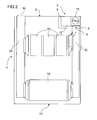
- FIG. 1 an insert 1 for a server rack 19 is shown, wherein the insert 1 has an air supply adapter 3 on its rear side 2.
- the air supply adapter 3 is a device which is designed so that it allows the entry of air into the slot 1. It comprises at least one opening 4 which points into the slot 1.
- the air supply adapter 3 is formed as a rectangular recess at the edge of the rectangular base of the drawer 1 and has a height which extends over part or all of the drawer 1. Furthermore, it has fastening devices 5 such as locking elements or screwing devices, via which a cuboid recess filling module 6 can be attached to the slot 1. Alternatively, it has devices for receiving bolts by means of which the module 6 can also be fastened.
- the air supply adapter 3 allows and controls the entry of air through the opening 4, which leads into the slot 1.
- a cooling channel 7 is formed, which is designed to cooperate with the opening 4.
- the module 6 also has a throttle device 8. Alternatively, the throttle device 8 may also be arranged on the air supply adapter 3.
- the module 6 has a connection 9 which protrudes from the rear side 2 of the insert 1.
- a cooling air hose 24 can be connected to connect the cooling air hose 24 with the cooling channel 7.
- the drawer 1 has a plurality of heat generating units 10. At the front 11 of the drawer 1 is dispensed air supply openings.
- the heat-producing Units 10 can thus be arranged on the complete front 11 of the insert 1.
- hot-pluggable mounting components such as CD-ROM drives and hard disk are arranged.
- the cooling channel 7 is connected via the opening 4 to a cooling channel system 12.
- the cooling channel 7 and the cooling channel system 12 are formed for example as an air guide cover made of sheet metal or plastic.
- the cross sections of the outlet openings of the cooling channel system 12 are matched to the size of the heat generating units 10.
- the air supply adapter 3 has for this purpose a further opening 14, which has in the slot 1, on.
- a connection channel 15 is formed between the further opening 14 and a further connection 16, so that the heated air can escape from the further connection 16.
- a cooling air hose 24 can be connected.
- FIG. 2 an alternative embodiment is shown.
- a fan module 17 is inserted in the air supply adapter 3.
- the cooling passage system 12 and the heat generating units 10 are analogous to those in FIG FIG. 1 illustrated embodiment formed.
- the fan module 17 has a fan 18.
- the fan 18 sucks air from the back 2 of the drawer 1 and blows them through the opening 4 in the cooling channel system 12.
- Hier the ambient air of the fan module 17 on the back 2 of the drawer 1 must be sufficiently cold. Therefore, the further connection 16 from which the air heated by the heat-generating units 10 exits air, in this embodiment, on the fan module 17 opposite side of the back 2 of the insert 1 is arranged.
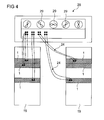
- FIG. 3 is shown as a further embodiment, a cooling circuit in a server rack 19 schematically.
- a cooling drawer 20 and two bays 1 with heat generating units 10 (not shown) are arranged vertically one above the other.
- the cooling drawer 20 has a sound insulation 21.
- the cooling drawer 20 has a cooling unit 22 and a flow generation unit 23.
- the inserts 1 are connected to the cooling drawer 20 through cooling air hoses 24.
- the bays 1 each have an air supply adapter 3, in which modules 6 are used, which are coupled via the cooling air hoses 24 to the cooling module 20.
- the modules 6 have throttle devices 8.
- the cooling unit 22 of the cooling insert 20 air is pre-cooled.
- the cooling unit 22 is designed, for example, as a heat exchanger. It has a control device 25, by means of which the temperature of the air used to cool the plug-in unit 1 can be adjusted.
- the cooling unit 22 may be formed as one or more fans 18, in which case the flow generating unit 23 and the cooling unit 22 are formed as one unit.
- the control device 25 may in this case control the speed of the fans 18 and thus the flow rate of the air.
- the flow-generating unit 23 transfers the pre-cooled air at the rear of the cooling insert 20 into the cooling air hoses 24.
- the pre-cooled air is supplied to the connections 9 of the inserts 1 via the cooling air hoses 24.
- the throttle device 8 is designed, for example, so that it can taper the opening 4 in the air supply adapter 3 and thus regulates the flow through the opening 4. It can be designed as a stopcock.
- the cooling drawer 20 has a plurality of outflow openings 26 and a plurality of inflow openings 27, to each of which cooling air hoses 24 can be connected.
- the cooling drawer 20 is thus designed as a central supply element, which can supply several bays 1.
- FIG. 4 shows an arrangement with two server racks 19 and an external cooling device 28.
- central fan 29 for cooling a plurality of slots 1 (shown hatched) are used, which are coupled by means of cooling air hoses 24 to the external cooling device 28. Not all inserts 1 must be coupled to the external cooling device 28.
- the arrangement is a cooling concept for a data center or even a server farm and may include more than two server racks 19.
- the waste heat is led out again in this example from the individual slots 1 and discharged to the external cooling device 28. Because of the engagement central fan 29, the use of many small fans in the slots 1 can be avoided.
- the external cooling device 28 may be located in the same room as well as outside the room in which the server racks 19 are. The cooling is then no longer caused by the direct ambient air of the slots 1.
- the external cooling device 28 is preferably configured redundantly. In the event of failure of one or more cooling units 22 cooling of all connected slots 1 is still ensured.
Landscapes
- Engineering & Computer Science (AREA)
- Computer Hardware Design (AREA)
- Physics & Mathematics (AREA)
- General Engineering & Computer Science (AREA)
- Theoretical Computer Science (AREA)
- Power Engineering (AREA)
- Human Computer Interaction (AREA)
- General Physics & Mathematics (AREA)
- Thermal Sciences (AREA)
- Microelectronics & Electronic Packaging (AREA)
- Cooling Or The Like Of Electrical Apparatus (AREA)
Abstract
Description
Die Erfindung betrifft einen Einschub für ein Serverrack, welcher Wärme erzeugende Einheiten aufweist.The invention relates to a slot for a server rack, which has heat generating units.
Die Erfindung betrifft weiterhin eine Anordnung mit einem Einschub für ein Serverrack, welcher Wärme erzeugende Einheiten aufweist und einer Kühlvorrichtung, welche eine Kühleinheit aufweist.The invention further relates to an arrangement with a slot for a server rack, which has heat-generating units and a cooling device, which has a cooling unit.
In einem 19"-Serverrack werden Server als Einschübe vertikal übereinander angeordnet. Im jedem Einschub werden in der Regel Mittel zur Kühlung von Wärme erzeugenden Einheiten angeordnet. Dabei ist üblicherweise vorgesehen, dass jeder Einschub integrierte Lüfter aufweist. Durch die Lüfter wird Luft durch die Vorderseite des Einschubs angesaugt, kühlt beim Vorbeiströmen die elektronischen, Wärme erzeugenden Einheiten und wird an der Rückseite des Einschubs wieder ausgeblasen.In a 19-inch server rack, servers are stacked vertically as stacks, and typically each unit provides cooling means for heat-generating units, usually with each unit having built-in fans sucked in the insert, cools when passing the electronic, heat-generating units and is blown out at the back of the insert again.
Beim Ausfall eines oder mehrerer Lüfter muss die Kühlung der Wärme erzeugenden Einheiten sichergestellt sein. Dazu sind in der Regel zusätzliche, redundante Lüfter in dem Einschub vorgesehen.In case of failure of one or more fans, the cooling of the heat generating units must be ensured. For this purpose, additional, redundant fans are usually provided in the slot.
Nachteilig ist, dass die Lüfter viel Platz innerhalb eines Einschubs benötigen. Zudem muss die Vorderseite eines Einschubs einen Bereich für den Kühllufteinlass aufweisen.The disadvantage is that the fans need a lot of space within a bay. In addition, the front of a drawer must have an area for the cooling air inlet.
Ein weiterer Nachteil ist, dass aufgrund der vorgegebenen kleinen Abmessungen die verwendeten Lüfter sehr ineffizient arbeiten. Sie erzeugen außerdem einen hohen Geräuschpegel.Another disadvantage is that due to the given small dimensions, the fans used are very inefficient. They also generate a high noise level.
Der Erfindung liegt die Aufgabe zugrunde, ein effizientes Kühlkonzept für Serverracks aufzuzeigen.The invention has for its object to provide an efficient cooling concept for server racks.
Die Aufgabe wird gelöst durch die Maßnahmen der unabhängigen Patentansprüche. Vorteilhafte Weiterbildungen sind Gegenstand der Unteransprüche.The object is achieved by the measures of the independent claims. Advantageous developments are the subject of the dependent claims.
Dementsprechend ist ein Einschub für ein Serverrack, welcher Wärme erzeugende Einheiten aufweist, vorgesehen, welcher zumindest ein Modul mit einem Anschluss zum Anschließen eines oder mehrerer Kühlluftschläuche an seiner Rückseite aufweist.Accordingly, an insert for a server rack having heat generating units is provided, which has at least one module with a connection for connecting one or more cooling air hoses on its rear side.
Im Vorderbereich des Einschubs werden keine Lüftungsöffnungen benötigt und es steht mehr Platz für Einbaukomponenten zur Verfügung. Die Lüfter sind aus dem Einschub herausgenommen. Innerhalb des Einschubs wird der Platz für Lüfter eingespart. Der Einschub kann damit kompakt und kostengünstig ohne Platzrestriktion an seiner Vorderseite mit Wärme erzeugenden Einheiten bestückt werden.There are no ventilation holes in the front of the drawer and more space is available for built-in components. The fans are removed from the slot. Inside the drawer, the space for fans is saved. The drawer can thus be equipped compactly and inexpensively without space restriction on its front with heat generating units.
In einer Ausgestaltung weist der Einschub ein Kühlkanalsystem auf, wobei das Modul mit dem Kühlkanalsystem gekoppelt ist und der oder die Kühlkanäle des Systems Kühlluft zu den Wärme erzeugenden Einheiten führen. Auf diese Weise entsteht eine wärmeübertragungsfähige Verbindung zwischen dem Modul und den Wärme erzeugenden Einheiten. Kühle Luft, welche durch den Anschluss von außen dem Gerät zugeführt wird kann mit Hilfe der Kühlkanäle den Wärme erzeugenden Einheiten direkt zugeführt werden.In one embodiment, the drawer has a cooling duct system, wherein the module is coupled to the cooling duct system and the one or more cooling ducts of the system lead cooling air to the heat generating units. In this way, a heat-transferable connection is created between the module and the heat-generating units. Cool air, which is supplied by the connection from the outside of the device can be supplied directly to the heat generating units by means of the cooling channels.
In einer vorteilhaften Ausgestaltung wird die von den Wärme erzeugenden Einheiten erwärmte Luft über die Rückseite des Einschubs abgeführt. Dies kann mit Hilfe eines Kühlkanals oder eines Kühlkanalsystems erfolgen.In an advantageous embodiment, the heated air from the units generating heat over the back of the Slid removed. This can be done by means of a cooling channel or a cooling channel system.
In einer vorteilhaften Ausgestaltung der Erfindung kann das Modul eine Drosselvorrichtung zur Einstellung des Luftdrucks der zugeführten Luft aufweisen. Über den Luftdruck kann die Kühlung eines Einschubs auf den Bedarf eingestellt werden.In an advantageous embodiment of the invention, the module may have a throttle device for adjusting the air pressure of the supplied air. About the air pressure, the cooling of a drawer can be adjusted to the needs.
In vorteilhaften Ausgestaltungen können Hotplug-fähige Einheiten, das heißt Einheiten, welche bei laufendem Betrieb des Serverracks angeschlossen werden können, über die komplette Vorderseite des Einschubs angeordnet werden.In advantageous embodiments, hot-pluggable units, that is to say units which can be connected while the server rack is in operation, can be arranged over the complete front of the drawer.
Die Aufgabe wird weiterhin gelöst durch eine Anordnung mit einer Kühlvorrichtung, wobei die Kühlvorrichtung eine Kühleinheit aufweist, an welche ein oder mehrere Kühlluftschläuche angeschlossen sind, welche Kühlluft von der Kühleinheit aus der Kühlvorrichtung herausleiten können und einem Einschub für ein Serverrack, welcher ein Modul mit einem Anschluss zum Anschließen eines oder mehrerer Kühlluftschläuche an der Rückseite aufweist.The object is further achieved by an arrangement with a cooling device, wherein the cooling device has a cooling unit to which one or more cooling air hoses are connected, which can lead cooling air from the cooling unit from the cooling device and a slot for a server rack, which is a module with a Connection for connecting one or more cooling air hoses on the back.
Die Anordnung kann weiterhin Kühlluftschläuche umfassen, welche sowohl an der Kühlvorrichtung als auch an den Einschub angeschlossen sind, wobei ein Anschluss der Kühlluftschläuche an die Geräte diese so verbindet, dass die Kühlvorrichtung kühle Luft durch die Kühlluftschläuche in den Einschub mit den Wärme erzeugenden Einheiten überführen kann. Die Kühlvorrichtung kann zu diesem Zweck eine Kühleinheit aufweisen, beispielsweise einen Wärmetauscher, sowie eine Strömungserzeugungseinheit, beispielsweise einen Lüfter.The assembly may further include cooling air hoses connected to both the cooling device and the drawer, with a connection of the cooling air hoses to the devices connecting them so that the cooling device can transfer cool air through the cooling air hoses into the drawer with the heat generating units , The cooling device may for this purpose comprise a cooling unit, for example a heat exchanger, as well as a flow generation unit, for example a fan.
Die Kühlvorrichtung kann als Kühleinschub ausgebildet sein, der in das Serverrack eingebaut werden kann.The cooling device can be designed as a cooling insert, which can be installed in the server rack.
In einem Serverrack, in welchem die Einschübe vertikal übereinander angeordnet sind, kann der Kühleinschub höher ausgebildet sein als der Einschub mit dem Modul an seiner Rückseite. Dadurch sind Lüfter einsetzbar, welche in ihrem Durchmesser größer sind als die Höhe des Einschubs mit dem Modul und den Wärme erzeugenden Einheiten. Größere Lüfter arbeiten effizienter und sparen dadurch Energie ein.In a server rack, in which the slots are arranged vertically one above the other, the cooling slot can be made higher than the slot with the module on its rear side. As a result, fans are used, which are larger in diameter than the height of the insert with the module and the heat generating units. Larger fans work more efficiently and save energy.
Die Aufgabe wird weiterhin gelöst durch eine Anordnung mit einem Serverrack, einer Kühlvorrichtung für das Serverrack, welche zumindest eine Kühleinheit aufweist, wobei an die Kühlvorrichtung ein oder mehrere Kühlluftschläuche angeschlossen sind und einem Einschub für das Serverrack, wobei der Einschub zumindest ein Modul mit einem Anschluss zum Anschließen eines oder mehrerer Kühlluftschläuche an der Rückseite aufweist.The object is further achieved by an arrangement with a server rack, a cooling device for the server rack, which has at least one cooling unit, wherein one or more cooling air hoses are connected to the cooling device and a slot for the server rack, the slot at least one module with a connection for connecting one or more cooling air hoses on the back.
Das Kühlkonzept betrifft in einer vorteilhaften Weiterbildung Serverfarmen und Rechenzentren. Die Kühlvorrichtung kann sowohl ein Serverrack als auch mehrere Serverracks mit Kühlluft versorgen. Dabei kann die Kühlvorrichtung in demselben Raum wie auch außerhalb des Raums, in welchem die Serverracks sind, angeordnet sein.The cooling concept relates in an advantageous development server farms and data centers. The cooling device can supply both a server rack and several server racks with cooling air. In this case, the cooling device can be arranged in the same room as outside the room in which the server racks are.
In vorteilhaften Ausgestaltungen weist die Kühleinheit eine Regelvorrichtung auf, mittels welcher die Temperatur der Luft, welche aus der Kühlvorrichtung herausgeleitet wird, einstellbar ist. Die Regelvorrichtung ist bevorzugt von der Außenseite der Kühlvorrichtung bedienbar.In advantageous embodiments, the cooling unit has a control device, by means of which the temperature of the air, which is led out of the cooling device, is adjustable. The control device is preferably operable from the outside of the cooling device.
Durch die Verwendung vorgekühlter Luft steht ein weiterer Regelungsparameter zur Verfügung. Die Kühlung kann durch die Strömungsgeschwindigkeit und durch die Temperatur der Luft geregelt werden.By using pre-cooled air, another control parameter is available. The cooling can be regulated by the flow velocity and the temperature of the air.
Die Aufgabe wird weiterhin gelöst durch einen Einschub für ein Serverrack, welcher an seiner Rückseite zumindest einen Luftzuführungsadapter aufweist, sowie Wärme erzeugende Einheiten, wobei in dem Luftzuführungsadapter entweder ein Modul mit einem Anschluss zum Anschließen eines oder mehrerer Kühlluftschläuche oder alternativ ein Lüftermodul einsetzbar ist.The object is further achieved by a slot for a server rack, which has at least one air supply adapter on its rear side, and heat generating units, wherein in the air supply adapter either a module with a connection for connecting one or more cooling air hoses or alternatively a fan module can be used.
Wenn ein Lüftermodul in den Luftzuführungsadapter eingesetzt wird, ist der Einschub in einem Serverrack ohne externe Kühlvorrichtung einsetzbar. Ist eine externe Kühlvorrichtung, wie zum Beispiel ein Kühleinschub vorgesehen, wird ein Modul mit einem Anschluss zum Anschließen eines oder mehrerer Kühlluftschläuche in den Luftzuführungsadapter eingesetzt und die Wärme erzeugenden Einheiten des Einschubs können durch die externe Kühlvorrichtung gekühlt werden.When a fan module is inserted into the air supply adapter, the drawer can be used in a server rack without an external cooling device. If an external cooling device, such as a cooling drawer, is provided, a module is inserted with a port for connecting one or more cooling air hoses into the air supply adapter, and the heat generating units of the drawer can be cooled by the external cooling device.
Weiterhin kann der Einschub ein Kühlkanalsystem aufweisen, welche den Luftzuführungsadapter mit den Wärme erzeugenden Einheiten verbindet.Furthermore, the drawer may have a cooling duct system which connects the air supply adapter with the heat generating units.
In einer weiteren Ausgestaltung kann die von den Wärme erzeugenden Einheiten erwärmte Luft über ein weiteres Kühlkanalsystem dem Luftzuführungsadapter zugeführt und über die Rückseite wieder aus dem Gerät herausgeleitet werden.In a further refinement, the air heated by the heat-generating units can be supplied to the air supply adapter via a further cooling channel system and be led out of the device again via the rear side.
Der Luftzuführungsadapter kann eine Drosselvorrichtung aufweisen, durch welche der Druck der zugeführten Luft einstellbar ist.The air supply adapter may include a throttle device by which the pressure of the supplied air is adjustable.
Weiterhin kann der Einschub über seine gesamte Vorderseite Hotplug-fähige Einheiten aufweisen.Furthermore, the drawer can have hotplug-enabled units over its entire front.
Der Einschub kann durch Kühlluftschläuche mit einer Kühlvorrichtung verbunden werden, etwa einem Kühleinschub in einem Serverrack. Er kann in einem Serverrack angeordnet sein und durch Kühlluftschläuche mit einer Kühlvorrichtung verbunden sein, welche außerhalb des Serverracks angeordnet ist.The drawer can be connected by cooling air hoses to a cooling device, such as a cooling drawer in a server rack. It can be arranged in a server rack and be connected by cooling air hoses with a cooling device, which is arranged outside the server rack.
Nachfolgend werden weitere Vorteile der Erfindung anhand mehrerer Ausführungsbeispiele erläutert.Hereinafter, further advantages of the invention will be explained with reference to several embodiments.
- Figur 1FIG. 1
- eine schematische Innenansicht eines Einschubs,a schematic interior view of a drawer,
- Figur 2FIG. 2
- eine weitere schematische Innenansicht eines Einschubs,another schematic interior view of a drawer,
- Figur 3FIG. 3
- eine schematische Perspektivansicht einer Anordnung mit einem Serverrack, zwei Einschüben und einem Kühleinschub unda schematic perspective view of an arrangement with a server rack, two slots and a cooling slide and
- Figur 4FIG. 4
- eine schematische Seitenansicht einer Anordnung mit einer Kühlvorrichtung und zwei Serverracks.a schematic side view of an arrangement with a cooling device and two server racks.
In
Der Luftzuführungsadapter 3 ist eine Vorrichtung, welche so ausgebildet ist, dass sie den Eintritt von Luft in den Einschub 1 ermöglicht. Er umfasst zumindest eine Öffnung 4, welche in den Einschub 1 weist. Der Luftzuführungsadapter 3 ist als rechteckige Aussparung an dem Rand der rechteckigen Grundfläche des Einschubs 1 ausgebildet und weist eine Höhe auf, welche sich über einen Teil oder den ganzen Einschub 1 erstreckt. Weiterhin weist er Befestigungsvorrichtungen 5 wie Rastelemente oder Schraubvorrichtungen auf, über die ein die quaderförmige Aussparung ausfüllendes Modul 6 an den Einschub 1 befestigt werden kann. Alternativ weist er Vorrichtungen zur Aufnahme von Bolzen auf mittels welcher das Modul 6 ebenfalls befestigt werden kann. Der Luftzuführungsadapter 3 ermöglicht und regelt den Eintritt von Luft durch die Öffnung 4, welche in den Einschub 1 führt. In dem Modul 6 ist ein Kühlkanal 7 ausgebildet, welcher ausgestaltet ist, mit der Öffnung 4 zusammenzuwirken. Das Modul 6 weist weiterhin eine Drosselvorrichtung 8 auf. Alternativ kann die Drosselvorrichtung 8 auch am Luftzuführungsadapter 3 angeordnet sein.The
Das Modul 6 weist einen Anschluss 9 auf, der aus der Rückseite 2 des Einschubs 1 herausragt. An den Anschluss 9 kann ein Kühlluftschlauch 24 angeschlossen werden, um den Kühlluftschlauch 24 mit dem Kühlkanal 7 zu verbinden.The
Der Einschub 1 weist mehrere Wärme erzeugende Einheiten 10 auf. An der Vorderseite 11 des Einschubs 1 wird auf Luftzuführungsöffnungen verzichtet. Die Wärme erzeugenden Einheiten 10 können somit an der kompletten Vorderseite 11 des Einschubs 1 angeordnet werden. An der Vorderseite 11 sind zum Beispiel Hotplug-fähige Einbaukomponenten wie CD-ROM-Laufwerke und Festplatte angeordnet.The
Der Kühlkanal 7 ist über die Öffnung 4 an ein Kühlkanalsystem 12 angeschlossen. Der Kühlkanal 7 und das Kühlkanalsystem 12 sind beispielsweise als Luftleithaube aus Blech oder Plastik ausgebildet. Die Querschnitte der Austrittsöffnungen des Kühlkanalsystems 12 sind auf die Größe der Wärme erzeugenden Einheiten 10 abgestimmt.The cooling
Im Betrieb des Einschubs 1 in einem Serverrack 19 wird die Luft, welche sich an den Wärme erzeugenden Einheiten 10 erwärmt über ein weiteres Kühlkanalsystem 13 zur Rückseite 2 des Einschubs 1 geführt. Dort kann sie aus dem Einschub 1 austreten. Der Luftzuführungsadapter 3 weist zu diesem Zweck eine weitere Öffnung 14, welche in den Einschub 1 weist, auf. In dem Luftzuführungsadapter 3 ist ein Verbindungskanal 15 zwischen der weiteren Öffnung 14 und einem weiteren Anschluss 16 ausgebildet, so dass die erwärmte Luft aus dem weiteren Anschluss 16 austreten kann. An den weiteren Anschluss 16 kann ein Kühlluftschlauch 24 angeschlossen werden.During operation of the
In
Das Lüftermodul 17 weist einen Lüfter 18 auf. Der Lüfter 18 saugt Luft von der Rückseite 2 des Einschubs 1 an und bläst diese über die Öffnung 4 in das Kühlkanalsystem 12. Hierbei muss die Umgebungsluft des Lüftermoduls 17 an der Rückseite 2 des Einschubs 1 ausreichend kalt sein. Deshalb ist der weitere Anschluss 16, aus dem die von den Wärme erzeugenden Einheiten 10 erwärmte Luft austritt, in diesem Ausführungsbeispiel auf der dem Lüftermodul 17 entgegen gesetzten Seite der Rückseite 2 des Einschubs 1 angeordnet.The
In
In der Kühleinheit 22 des Kühleinschubs 20 wird Luft vorgekühlt. Die Kühleinheit 22 ist beispielsweise als Wärmetauscher ausgebildet. Sie weist eine Regelvorrichtung 25 auf, mittels welcher die Temperatur der Luft, die zur Kühlung des oder der Einschübe 1 verwendet wird, eingestellt werden kann. Alternativ kann die Kühleinheit 22 als ein oder mehrere Lüfter 18 ausgebildet sein, wobei in diesem Fall die Strömungserzeugungseinheit 23 und die Kühleinheit 22 als eine Einheit ausgebildet sind. Die Regelvorrichtung 25 kann in dem Fall die Drehzahl der Lüfter 18 und damit die Strömungsgeschwindigkeit der Luft steuern.In the
Die Strömungserzeugungseinheit 23 überführt die vorgekühlte Luft an der Rückseite des Kühleinschubs 20 in die Kühlluftschläuche 24. Über die Kühlluftschläuche 24 wird die vorgekühlte Luft den Anschlüssen 9 der Einschübe 1 zugeführt.The flow-generating
Mit Hilfe der Drosselvorrichtungen 8 an den Einschüben 1 kann der Druck der zugeführten Luft eingestellt werden. Die Drosselvorrichtung 8 ist beispielsweise so ausgebildet, dass sie die Öffnung 4 im Luftzuführungsadapter 3 verjüngen kann und so den Durchfluss durch die Öffnung 4 regelt. Sie kann als Absperrhahn ausgebildet sein.With the help of the
In dem dargestellten Ausführungsbeispiel weist der Kühleinschub 20 mehrere Ausströmöffnungen 26 und mehrere Einströmöffnungen 27 auf, an welche jeweils Kühlluftschläuche 24 angeschlossen werden können. Der Kühleinschub 20 ist somit als ein zentrales Versorgungselement ausgebildet, welches mehrere Einschübe 1 versorgen kann.In the illustrated embodiment, the
Die Anordnung ist ein Kühlkonzept für ein Rechenzentrum oder auch eine Serverfarm und kann mehr als zwei Serverracks 19 umfassen. Die Abwärme wird in diesem Beispiel aus den einzelnen Einschüben 1 wieder herausgeführt und an die externe Kühlvorrichtung 28 abgeführt. Durch den Einsatz zentraler Lüfter 29 kann der Einsatz vieler kleiner Lüfter in den Einschüben 1 vermieden werden.The arrangement is a cooling concept for a data center or even a server farm and may include more than two server racks 19. The waste heat is led out again in this example from the
Die externe Kühlvorrichtung 28 kann in demselben Raum, sowie auch außerhalb des Raums, in welchem die Serverracks 19 sind, angeordnet sein. Die Kühlung wird dann nicht mehr durch die direkte Umgebungsluft der Einschübe 1 bewirkt.The
Die externe Kühlvorrichtung 28 ist bevorzugt redundant ausgelegt. Bei dem Ausfall einer oder mehrerer Kühleinheiten 22 ist eine Kühlung aller angeschlossener Einschübe 1 dennoch sichergestellt.The
Bezugszeichenliste
- 1
- Einschub
- 2
- Rückseite
- 3
- Luftzuführungsadapter
- 4
- Öffnung
- 5
- Befestigungsvorrichtung
- 6
- Modul
- 7
- Kühlkanal
- 8
- Drosselvorrichtung
- 9
- Anschluss
- 10
- Wärme erzeugende Einheiten
- 11
- Vorderseite
- 12
- Kühlkanalsystem
- 13
- weiteres Kühlkanalsystem
- 14
- weitere Öffnung
- 15
- Verbindungskanal
- 16
- weiterer Anschluss
- 17
- Lüftermodul
- 18
- Lüfter
- 19
- Serverrack
- 20
- Kühleinschub
- 21
- Schalldämmung
- 22
- Kühleinheit
- 23
- Strömungserzeugungseinheit
- 24
- Kühlluftschlauch
- 25
- Regelvorrichtung
- 26
- Ausströmöffnungen
- 27
- Einströmöffnungen
- 28
- Kühlvorrichtung
- 29
- zentraler Lüfter
- 1
- insertion
- 2
- back
- 3
- Air supply adapter
- 4
- opening
- 5
- fastening device
- 6
- module
- 7
- cooling channel
- 8th
- throttling device
- 9
- connection
- 10
- Heat generating units
- 11
- front
- 12
- Cooling duct system
- 13
- another cooling channel system
- 14
- further opening
- 15
- connecting channel
- 16
- further connection
- 17
- fan module
- 18
- Fan
- 19
- server rack
- 20
- A cooling rack
- 21
- soundproofing
- 22
- cooling unit
- 23
- Flow generating unit
- 24
- Cooling air hose
- 25
- control device
- 26
- outflow
- 27
- inflow
- 28
- cooler
- 29
- central fan
Claims (20)
dadurch gekennzeichnet, dass
der Einschub (1) ein Kühlkanalsystem (12) aufweist, wobei das Modul (6) mit dem Kühlkanalsystem (12) gekoppelt ist und das Kühlkanalsystem (12) Kühlluft zu den Wärme erzeugenden Einheiten führt.Insert (1) for a server rack (19) according to claim 1,
characterized in that
the drawer (1) has a cooling duct system (12), wherein the module (6) is coupled to the cooling duct system (12) and the cooling duct system (12) supplies cooling air to the heat generating units.
dadurch gekennzeichnet, dass
Luft, welche sich durch die Wärme erzeugenden Einheiten (10) erwärmt, über die Rückseite (2) des Einschubs (1) aus dem Einschub (1) abgeführt wird.Insert (1) for a server rack (19) according to claim 1 or 2,
characterized in that
Air, which is heated by the heat generating units (10), is discharged from the drawer (1) via the rear side (2) of the drawer (1).
dadurch gekennzeichnet, dass
das Modul (6) eine Drosselvorrichtung (8) zur Einstellung des Luftdrucks der zugeführten Luft aufweist.Insert (1) for a server rack (19) according to one of the preceding claims,
characterized in that
the module (6) has a throttle device (8) for adjusting the air pressure of the supplied air.
dadurch gekennzeichnet, dass
der Einschub (1) an seiner Vorderseite (11) Hotplug-fähige Einheiten aufweist.Insert (1) for a server rack (19) according to one of the preceding claims,
characterized in that
the drawer (1) has on its front side (11) hot-pluggable units.
dadurch gekennzeichnet, dass
der Einschub (1) in einem Serverrack (19) angeordnet ist.Arrangement according to claim 6,
characterized in that
the drawer (1) is arranged in a server rack (19).
dadurch gekennzeichnet, dass
die Kühlvorrichtung (28) als Kühleinschub (20) für das Serverrack (19) ausgebildet ist.Arrangement according to claim 6,
characterized in that
the cooling device (28) is designed as a cooling insert (20) for the server rack (19).
dadurch gekennzeichnet, dass
die Kühlvorrichtung (28) außerhalb des Serverracks (19) angeordnet ist.Arrangement according to claim 7,
characterized in that
the cooling device (28) is arranged outside the server rack (19).
dadurch gekennzeichnet, dass
die Kühleinheit (22) eine Regelvorrichtung aufweist.Arrangement according to one of the preceding claims 7 to 9,
characterized in that
the cooling unit (22) comprises a control device.
dadurch gekennzeichnet, dass
der Einschub (1) ein Kühlkanalsystem (12) aufweist, wobei der Luftzuführungsadapter (3) mit dem Kühlkanalsystem (12) gekoppelt ist und das Kühlkanalsystem (12) Kühlluft zu den Wärme erzeugenden Einheiten führt.Insert (1) according to the preceding claim,
characterized in that
the drawer (1) has a cooling duct system (12), wherein the air supply adapter (3) is coupled to the cooling duct system (12) and the cooling duct system (12) supplies cooling air to the heat generating units.
dadurch gekennzeichnet, dass
Luft, welche sich durch die Wärme erzeugenden Einheiten (10) erwärmt, über die Rückseite (2) des Einschubs (1) abgeführt wird.Insert (1) for a server rack (19) according to one of the preceding claims 11 or 12,
characterized in that
Air, which is heated by the heat generating units (10), via the back (2) of the insert (1) is discharged.
dadurch gekennzeichnet, dass
der Luftzuführungsadapter (3) eine Drosselvorrichtung (8) zur Einstellung des Luftdrucks der zugeführten Luft aufweist.Insert (1) for a server rack (19) according to one of the preceding claims 11 to 13,
characterized in that
the air supply adapter (3) has a throttle device (8) for adjusting the air pressure of the supplied air.
dadurch gekennzeichnet, dass
der Einschub (1) an seiner Vorderseite (11) Hotplug-fähige Einheiten aufweist.Insert (1) for a server rack (19) according to one of the preceding claims 11 to 14,
characterized in that
the drawer (1) has on its front side (11) hot-pluggable units.
dadurch gekennzeichnet, dass
der Einschub (1) in einem Serverrack (19) angeordnet ist.Arrangement according to claim 16,
characterized in that
the drawer (1) is arranged in a server rack (19).
dadurch gekennzeichnet, dass
die Kühlvorrichtung (28) als Kühleinschub (20) für das Serverrack (19) ausgebildet ist.Arrangement according to claim 16,
characterized in that
the cooling device (28) is designed as a cooling insert (20) for the server rack (19).
dadurch gekennzeichnet, dass
die Kühlvorrichtung (28) außerhalb des Serverracks (19) angeordnet ist.Arrangement according to claim 17,
characterized in that
the cooling device (28) is arranged outside the server rack (19).
dadurch gekennzeichnet, dass
die Kühleinheit (22) eine Regelvorrichtung aufweist.Arrangement according to one of the preceding claims 17 to 19,
characterized in that
the cooling unit (22) comprises a control device.
Applications Claiming Priority (1)
| Application Number | Priority Date | Filing Date | Title |
|---|---|---|---|
| DE200710056982 DE102007056982B3 (en) | 2007-11-27 | 2007-11-27 | Slot for a server rack and arrangement with a slot and a cooling device for a server rack |
Publications (2)
| Publication Number | Publication Date |
|---|---|
| EP2066164A2 true EP2066164A2 (en) | 2009-06-03 |
| EP2066164A3 EP2066164A3 (en) | 2012-12-26 |
Family
ID=40436457
Family Applications (1)
| Application Number | Title | Priority Date | Filing Date |
|---|---|---|---|
| EP08167541A Withdrawn EP2066164A3 (en) | 2007-11-27 | 2008-10-24 | Drawer for a server rack and assembly with a drawer and a cooling device for a server rack |
Country Status (2)
| Country | Link |
|---|---|
| EP (1) | EP2066164A3 (en) |
| DE (1) | DE102007056982B3 (en) |
Families Citing this family (1)
| Publication number | Priority date | Publication date | Assignee | Title |
|---|---|---|---|---|
| DE102015101304B3 (en) * | 2015-01-29 | 2016-03-17 | Fujitsu Technology Solutions Intellectual Property Gmbh | Rack server for a server rack |
Citations (3)
| Publication number | Priority date | Publication date | Assignee | Title |
|---|---|---|---|---|
| DE2223226A1 (en) * | 1972-05-12 | 1973-11-22 | Dieter Gaertner | DEVICE CABINET OD. DGL. WITH FAN INSERT |
| US6616525B1 (en) * | 2002-04-29 | 2003-09-09 | Hewlett-Packard Development Company, L.P. | Modular fan system |
| US20050259392A1 (en) * | 2004-05-21 | 2005-11-24 | Vinson Wade D | Computer system with external air mover |
Family Cites Families (11)
| Publication number | Priority date | Publication date | Assignee | Title |
|---|---|---|---|---|
| IT1032528B (en) * | 1974-08-29 | 1979-06-20 | Cselt Centro Studi Lab Telecom | THERMAL SYSTEM FOR CABINETS CONTAINING ELECTRICAL CIRCUITS |
| DE2740772C3 (en) * | 1977-09-09 | 1980-03-27 | Siemens Ag, 1000 Berlin Und 8000 Muenchen | Device for dissipating heat loss from electronic assemblies |
| DE3316978A1 (en) * | 1983-05-09 | 1984-11-15 | Siemens AG, 1000 Berlin und 8000 München | Construction system for dissipating the heat losses from electronic assemblies which are arranged in containers or cabinets |
| FR2651636B1 (en) * | 1989-09-06 | 1996-08-02 | Segem | MODULAR ELECTRONIC CONTAINER WITH INCORPORATED VENTILATION. |
| US5207613A (en) * | 1991-07-08 | 1993-05-04 | Tandem Computers Incorporated | Method and apparatus for mounting, cooling, interconnecting, and providing power and data to a plurality of electronic modules |
| US5321581A (en) * | 1992-03-20 | 1994-06-14 | Cray Research, Inc. | Air distribution system and manifold for cooling electronic components |
| US6522535B1 (en) * | 1997-10-23 | 2003-02-18 | Hewlett-Packard Company | Method and apparatus for cooling a portable computer in a docking station |
| US6765795B2 (en) * | 2002-07-23 | 2004-07-20 | Silicon Graphics, Inc. | Modular fan brick and method for exchanging air in a brick-based computer system |
| US7088581B2 (en) * | 2002-07-23 | 2006-08-08 | Silicon Graphics, Inc. | External fan and method for exchanging air with modular bricks in a computer system |
| US7345873B2 (en) * | 2004-09-29 | 2008-03-18 | General Electric Company | System and method for cooling electronic systems |
| US20070190920A1 (en) * | 2006-02-15 | 2007-08-16 | International Business Machines Corporation | Server cooling and exhaust appendage system |
-
2007
- 2007-11-27 DE DE200710056982 patent/DE102007056982B3/en not_active Expired - Fee Related
-
2008
- 2008-10-24 EP EP08167541A patent/EP2066164A3/en not_active Withdrawn
Patent Citations (3)
| Publication number | Priority date | Publication date | Assignee | Title |
|---|---|---|---|---|
| DE2223226A1 (en) * | 1972-05-12 | 1973-11-22 | Dieter Gaertner | DEVICE CABINET OD. DGL. WITH FAN INSERT |
| US6616525B1 (en) * | 2002-04-29 | 2003-09-09 | Hewlett-Packard Development Company, L.P. | Modular fan system |
| US20050259392A1 (en) * | 2004-05-21 | 2005-11-24 | Vinson Wade D | Computer system with external air mover |
Also Published As
| Publication number | Publication date |
|---|---|
| EP2066164A3 (en) | 2012-12-26 |
| DE102007056982B3 (en) | 2009-12-24 |
Similar Documents
| Publication | Publication Date | Title |
|---|---|---|
| EP1614333B1 (en) | Cooling system for equipment and wiring cabinets and method for cooling equipment and wiring cabinets | |
| DE60130171T2 (en) | Cooling for an electronic system | |
| DE102010051962B4 (en) | Cooling arrangement and working method for a fan control | |
| EP3310139B1 (en) | Module holder | |
| DE102011000638A1 (en) | Method and device for controlling and monitoring an air conditioning system for data processing systems | |
| DE102015101304B3 (en) | Rack server for a server rack | |
| DE102007061966B4 (en) | Arrangement for cooling electrical and electronic components and modular units in equipment cabinets | |
| EP2226701A1 (en) | Air conditioning system | |
| EP1705977B1 (en) | Housing for mounting plugable electronic units | |
| DE102010021019B9 (en) | Housing cabinet for holding a plurality of plug-in components and rack housing with the housing cabinet and an exhaust unit | |
| DE102008002789A1 (en) | Modular designed arrangement for heat-producing electronic device i.e. server, has supply air opening connected to warm and cold channel during multi-row arrangement of racks between channel and discharge air opening of conditioning device | |
| DE602006000099T2 (en) | Cooling system and method for an electronic device | |
| EP2087297A1 (en) | Climate control device | |
| DE202005004448U1 (en) | Housing for electronic components has a pair of motor driven radial flow fans built into the top of the housing | |
| DE102014201483B4 (en) | Cuboid housing for an electronics module, electronic module and arrangement for cooling at least one electronic module | |
| WO2016079119A1 (en) | Method and arrangement for air-conditioning a cold aisle | |
| EP1026932A2 (en) | Modular cabinet for electrical and electronic aggregates | |
| EP2066164A2 (en) | Drawer for a server rack and assembly with a drawer and a cooling device for a server rack | |
| DE102009030088B4 (en) | casing | |
| EP2909694B1 (en) | Arrangement for a computer system and computer system | |
| EP2034386A1 (en) | Computer housing with plug-in card module | |
| EP2410829B1 (en) | Cooling system for housed electronic equipment | |
| WO2012072694A1 (en) | Computer system and processor slide-in assembly therefor | |
| DE102005056096B4 (en) | Cooling arrangement for at least one plugged into a rack electrical assembly and method for cooling such an electrical assembly and rack with an assembly | |
| EP2190276A2 (en) | Device and method for cooling the interior of an electronics cabinet |
Legal Events
| Date | Code | Title | Description |
|---|---|---|---|
| PUAI | Public reference made under article 153(3) epc to a published international application that has entered the european phase |
Free format text: ORIGINAL CODE: 0009012 |
|
| AK | Designated contracting states |
Kind code of ref document: A2 Designated state(s): AT BE BG CH CY CZ DE DK EE ES FI FR GB GR HR HU IE IS IT LI LT LU LV MC MT NL NO PL PT RO SE SI SK TR |
|
| AX | Request for extension of the european patent |
Extension state: AL BA MK RS |
|
| RAP1 | Party data changed (applicant data changed or rights of an application transferred) |
Owner name: FUJITSU TECHNOLOGY SOLUTIONS INTELLECTUAL PROPERTY |
|
| PUAL | Search report despatched |
Free format text: ORIGINAL CODE: 0009013 |
|
| AK | Designated contracting states |
Kind code of ref document: A3 Designated state(s): AT BE BG CH CY CZ DE DK EE ES FI FR GB GR HR HU IE IS IT LI LT LU LV MC MT NL NO PL PT RO SE SI SK TR |
|
| AX | Request for extension of the european patent |
Extension state: AL BA MK RS |
|
| RIC1 | Information provided on ipc code assigned before grant |
Ipc: H05K 7/20 20060101AFI20121121BHEP Ipc: G06F 1/18 20060101ALI20121121BHEP |
|
| AKY | No designation fees paid | ||
| REG | Reference to a national code |
Ref country code: DE Ref legal event code: R108 |
|
| REG | Reference to a national code |
Ref country code: DE Ref legal event code: R108 Effective date: 20130904 |
|
| STAA | Information on the status of an ep patent application or granted ep patent |
Free format text: STATUS: THE APPLICATION IS DEEMED TO BE WITHDRAWN |
|
| 18D | Application deemed to be withdrawn |
Effective date: 20130627 |