EP2063337A2 - Method of detecting sources of interference on automation devices and unit for detecting sources of interference for same - Google Patents
Method of detecting sources of interference on automation devices and unit for detecting sources of interference for same Download PDFInfo
- Publication number
- EP2063337A2 EP2063337A2 EP08019453A EP08019453A EP2063337A2 EP 2063337 A2 EP2063337 A2 EP 2063337A2 EP 08019453 A EP08019453 A EP 08019453A EP 08019453 A EP08019453 A EP 08019453A EP 2063337 A2 EP2063337 A2 EP 2063337A2
- Authority
- EP
- European Patent Office
- Prior art keywords
- interference
- channels
- channel
- availability
- radio
- Prior art date
- Legal status (The legal status is an assumption and is not a legal conclusion. Google has not performed a legal analysis and makes no representation as to the accuracy of the status listed.)
- Granted
Links
- 238000000034 method Methods 0.000 title claims abstract description 15
- 230000005540 biological transmission Effects 0.000 claims abstract description 19
- 238000004891 communication Methods 0.000 claims description 21
- 238000001514 detection method Methods 0.000 claims description 12
- 230000003595 spectral effect Effects 0.000 claims description 9
- 238000001228 spectrum Methods 0.000 description 13
- 238000005516 engineering process Methods 0.000 description 8
- 239000013256 coordination polymer Substances 0.000 description 5
- 238000010586 diagram Methods 0.000 description 4
- 238000005259 measurement Methods 0.000 description 4
- 238000009434 installation Methods 0.000 description 2
- 230000003044 adaptive effect Effects 0.000 description 1
- 238000005352 clarification Methods 0.000 description 1
- 230000000694 effects Effects 0.000 description 1
- 238000011156 evaluation Methods 0.000 description 1
- 230000003278 mimic effect Effects 0.000 description 1
- 229920001690 polydopamine Polymers 0.000 description 1
Images


Classifications
-
- G—PHYSICS
- G05—CONTROLLING; REGULATING
- G05B—CONTROL OR REGULATING SYSTEMS IN GENERAL; FUNCTIONAL ELEMENTS OF SUCH SYSTEMS; MONITORING OR TESTING ARRANGEMENTS FOR SUCH SYSTEMS OR ELEMENTS
- G05B19/00—Programme-control systems
- G05B19/02—Programme-control systems electric
- G05B19/418—Total factory control, i.e. centrally controlling a plurality of machines, e.g. direct or distributed numerical control [DNC], flexible manufacturing systems [FMS], integrated manufacturing systems [IMS] or computer integrated manufacturing [CIM]
- G05B19/4184—Total factory control, i.e. centrally controlling a plurality of machines, e.g. direct or distributed numerical control [DNC], flexible manufacturing systems [FMS], integrated manufacturing systems [IMS] or computer integrated manufacturing [CIM] characterised by fault tolerance, reliability of production system
-
- H—ELECTRICITY
- H04—ELECTRIC COMMUNICATION TECHNIQUE
- H04W—WIRELESS COMMUNICATION NETWORKS
- H04W16/00—Network planning, e.g. coverage or traffic planning tools; Network deployment, e.g. resource partitioning or cells structures
- H04W16/14—Spectrum sharing arrangements between different networks
-
- Y—GENERAL TAGGING OF NEW TECHNOLOGICAL DEVELOPMENTS; GENERAL TAGGING OF CROSS-SECTIONAL TECHNOLOGIES SPANNING OVER SEVERAL SECTIONS OF THE IPC; TECHNICAL SUBJECTS COVERED BY FORMER USPC CROSS-REFERENCE ART COLLECTIONS [XRACs] AND DIGESTS
- Y02—TECHNOLOGIES OR APPLICATIONS FOR MITIGATION OR ADAPTATION AGAINST CLIMATE CHANGE
- Y02P—CLIMATE CHANGE MITIGATION TECHNOLOGIES IN THE PRODUCTION OR PROCESSING OF GOODS
- Y02P90/00—Enabling technologies with a potential contribution to greenhouse gas [GHG] emissions mitigation
- Y02P90/02—Total factory control, e.g. smart factories, flexible manufacturing systems [FMS] or integrated manufacturing systems [IMS]
Definitions
- the invention relates to a method for detecting sources of interference for automation equipment having a plurality of coupled via a data bus input / output modules, of which at least one is set up as a radio input / output module for radio data communication, said at least one wireless on - / output module constantly checks the availability of transmission channels for radio data transmission repeatedly and stores the availability of a sequence of transmission channels in a channel list.
- the invention further relates to an interference source identification unit having a comparison unit, a data memory and a data bus communication unit which is set up for data communication with radio input / output modules of an automation device via a data bus.
- Radio input / output modules for radio data communication.
- the radio solutions described are very often based on standard consumer technologies.
- Classic standard technologies are IEEE 802.15.1 (Bluetooth) and IEEE 802.11 (WLAN) as well as other proprietary technologies that operate in respective frequency ranges, in particular in the 2.4 GHz ISN frequency band. Accordingly, it can happen that the radio systems interfere with each other as far as they communicate with each other at a short distance.
- the radio data communication is in industrial automation equipment, especially problematic because often parallel to this WLAN wireless networks can be set up and also have module consumer devices, such as PDAs, notebooks, etc., mobile phones, etc., integrated wireless technologies with 2.45 GHz ISN frequency band.
- module consumer devices such as PDAs, notebooks, etc., mobile phones, etc.
- integrated wireless technologies with 2.45 GHz ISN frequency band.
- Such measures can be, for example, the setting of a different frequency channel, the change in the installation position of transmitter and receiver or the use of antennas with directional effects.
- EP 1 449 397 B1 discloses a method of interference measurements on wireless communication systems in which it is monitored whether a carrier is free. A mutual interference of different radio systems should be avoided by a channel is replaced by interference measurements by less disturbed. Interference disturbed channels are detected by a continuous or quasi-continuous interference measurement.
- EP 1 717 997 A1 discloses a method for reducing interference in short-range radio networks by other devices in the same frequency band. Interference-prone channels of the Bluetooth network are excluded from traffic and the remaining channels are split by a channel controller onto multiple Bluetooth networks. Disturbance is detected by means of a channel measuring unit which detects interferences and Interference information transmitted to a channel controller.
- the method makes use of the fact that standard technologies for wireless data communication usually carry out an availability measurement of channels in order to carry out data transmission in a defined frequency band only in the available, undisturbed channels.
- Bluetooth technology uses the so-called "Slow Frequency Hopping Spread Spectrum" (SFHSS) method to reduce the interference of other active sources of interference in the 2.45 GHz ISM frequency band.
- SFHSS Small Frequency Hopping Spread Spectrum
- the 2.45 GHz ISM frequency band is divided into 79 logical channels with a bandwidth of 1 MHz.
- For transmission of each data packet exclusively a logical channel is used. Thereafter, another channel is computed pseudo-randomly from the 79 possible channels used to transmit the subsequent data packet. In this respect, the probability is reduced that data packet collisions occur between coexisting radio solutions, or interfere with other active sources of interference.
- Bluetooth technology incorporates an adaptive frequency hopping technique in which the logical channels are evaluated using spectral noise power in the 2.45 GHz ISM frequency band during active data exchange. If faults are detected in one or more of the 79 channels, the Bluetooth system excludes the at least one faulty channel from the frequency hopping sequence. The communication then continues on the remaining channels.
- the current status of the available channels can be queried from the Bluetooth transceiver via the standardized "Host Controller Interface” (HCl).
- HCl command “Read_AFH_Channel_Map” can be used, which in the form of a bit mask can indicate the existence of channel disturbances.
- a binary "0" at a bit position signals a (unusable) channel that is currently subject to active interference and has been hidden for communication. A binary "1", however, indicates that the channel is undisturbed.
- Such a bit mask for the 79 channels of the 2.45 GHz ISM frequency band can thus be used as a channel list by not only hiding individual channels for data communication, as is known from Bluetooth technology. Rather, the bit masks (channel lists) in the case of the presence of interference sources to characteristic bit patterns, which are evaluated according to the teaching of the present invention for the detection of sources of interference.
- the evaluation of the logical transmission channels by the radio input / output modules of the automation device is preferably carried out on the basis of the spectral interference power in the respective frequency band, for which the radio input / output modules are set up.
- the spectral noise power is evaluated in the 2.45 GHz ISM frequency band.
- the individual channels of the frequency band are then identified with a bit coding as undisturbed or disturbed channel and this bit coding of the channels of a frequency band is then transmitted as a channel pattern to a Störttlenerkennungsaku, which is connected via a radio input / output module.
- the at least one channel pattern preferably a multiplicity of channel patterns of a plurality of radio input / output modules present in the automation device, is then evaluated in the interference source identification unit.
- the type of interference source can be based on the course of the disturbed channels be recognized.
- the characteristic course of the spectrum of a source of interference can be characterized, for example, by interference power at certain, non-adjacent frequency bands.
- the detection of the type of interference source can also be based on the frequency bandwidth of a sequence of contiguous continuously disturbed channels. For example, continuously disturbed frequency ranges of 3 MHz width can shoot at an IEEE 802.15.4 O-QPSK based radio system.
- An IEEE 802.11 BIG WLAN radio system emits interference affecting an approximately 20 MHz wide spectrum.
- microwave systems can be characterized by two spectral signal components, a bandwidth of approximately 10 MHz each. They thus have a characteristic spectral course.
- the object of the present invention is also to provide an improved interference source detection unit, with which a detection of interference sources in an automation device can be carried out in a cost-effective and simple manner.
- the implementation is achieved with the interference source detection unit of the type mentioned above in that the data communication unit is further configured to read channel patterns currently stored in channel lists of connected radio input / output modules, which identify the availability of transmission channels for radio data transmission, and in that the comparison unit for comparing the availability of the sequence of channels with a number of interference source channel patterns stored for a number of different interference sources and detecting a source of interference when the channel pattern defined by the availability of the sequence of channels has a predetermined minimum similarity to one of the stored interference source channel patterns is.
- FIG. 1 allows an automation device 1 recognize that in a conventional manner a plurality of input / output modules 2a, 2b ..., 2n, which are networked together via a data bus 3.
- the sequence of input / output modules 2a, 2b..., 2n can be connected to a field bus 5 via a fieldbus coupler 4 in order to connect it to a higher-order control unit 6.
- the automation device 1 can in this way, for example, 1, 2, 3 or more compilations of fieldbus coupler 4 and input / output modules 2 have.
- Such a sequence of fieldbus coupler 4 and input / output modules 2a, 2b, ..., 2n is, for example, placed adjacent to one another next to a DIN rail.
- a selection of input / output modules 2a, 2b..., 2n can be designed for radio data communication and form a respectively special radio input / output module 6, which with respect to a transmitting / receiving unit 7 and an antenna 8 via radio Participants of the automation device 1 communicates.
- the automation device 1 also has a Störttlenerkennungsaku 9, which may be integrated into the central control unit 6 or may be a separate, connectable to the data bus 3 or the field bus 5 noise source detection module.
- the interference source detection unit 9 can also be integrated in the fieldbus coupler 4 or in an input / output module 2a, 2b, 2n or a radio input / output module 6.
- the interference source identification unit 9 has a data bus communication unit 10 with an interface and an interface controller for data communication with radio input / output modules 6 of the automation device 1 via the data bus 3, 5. Furthermore, the interference source detection unit 9 has a data memory 11 in which characteristic interference source channel patterns of known interference sources are stored. A comparison unit 12 of the interference source identification unit 9 accesses the data memory 11 and the data bus communication unit 10 in order to read out the stored interference source channel patterns from the data memory 11 and channel lists CL from connected radio input / output modules 6 and to compare them with one another. The channel lists CL read from the radio input / output modules 6 contain information about the availability of a sequence of transmission channels of a frequency band. The individual channels of the frequency band are characterized by a bit coding as undisturbed or disturbed channel.
- the comparison unit 12 determines the presence of interference sources and their type in the environment of the automation device, without additional metrological effort and additional hardware being required ,
- the information available on the availability of channels in the radio input / output modules 6 is used in any case.
- the fact that the bit codings of the sequence of channels of a frequency band for certain interferers adopt characteristic patterns is used to detect the presence and type of interference sources.
- FIG. 2 shows a sketch of a diagram of the spectrum of a characteristic spectrum of a WLAN radio system according to IEEE 802.11 b / g.
- a WLAN radio signal in the 2.4 GHz ISM frequency band has a frequency band range of a bandwidth of about 20 MHz.
- the associated channel list CL or interference source channel pattern CP contains a bit pattern in which each channel is binary-coded.
- One of the values "0" signals an unused channel, ie the channel is currently subject to active interference and has been sent out for communication.
- the value "1" indicates that the channel is undisturbed.
- FIG. 3 Fig. 11 shows a diagram and noise source channel pattern CP characteristic of microwave systems.
- microwave systems have a spectrum that can characterize the center frequency of 2.45 GHz through 2 spectral signal components at a bandwidth of 10 MHz each. It is conceivable that other sources of interference mimic microwave emissions with other characteristic signal curves.
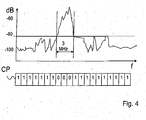
- FIG. 4 shows the sketch of a diagram of a spectrum of an IEEE 802.15.4 O-QPSK signal in the 2.4 GHz ISM frequency range as well as an associated noise source channel pattern CP. It can be seen that the signal has a bandwidth of about 3 MHz, a signal level of more than about -65 dB.
- characteristic spectra of the signal emitted by the interference source and associated binary interference source channel patterns CP can be detected for a large number of interference sources, which can be used for comparison with the bit codes of the read-out channel lists CL.
Landscapes
- Engineering & Computer Science (AREA)
- General Engineering & Computer Science (AREA)
- Manufacturing & Machinery (AREA)
- Quality & Reliability (AREA)
- Physics & Mathematics (AREA)
- General Physics & Mathematics (AREA)
- Automation & Control Theory (AREA)
- Mobile Radio Communication Systems (AREA)
- Monitoring And Testing Of Transmission In General (AREA)
- Noise Elimination (AREA)
Abstract
Description
Die Erfindung betrifft ein Verfahren zur Erkennung von Störquellen für Automatisierungseinrichtungen, die eine Vielzahl von über einen Datenbus miteinander gekoppelter Ein-/Ausgabemodule haben, von denen mindestens eines als Funk-Ein-/Ausgabemodul zur Funkdatenkommunikation eingerichtet ist, wobei das mindestens eine Funk-Ein-/Ausgabemodul die Verfügbarkeit von Übertragungskanälen zur Funkdatenübertragung ständig wiederholt überprüft und die Verfügbarkeit einer Folge von Übertragungskanälen in einer Kanalliste abspeichert.The invention relates to a method for detecting sources of interference for automation equipment having a plurality of coupled via a data bus input / output modules, of which at least one is set up as a radio input / output module for radio data communication, said at least one wireless on - / output module constantly checks the availability of transmission channels for radio data transmission repeatedly and stores the availability of a sequence of transmission channels in a channel list.
Die Erfindung betrifft weiterhin eine Störquellenerkennungseinheit mit einer Vergleichseinheit, einem Datenspeicher und einer Datenbus-Kommunikationseinheit, die zur Datenkommunikation mit Funk-Ein-/Ausgabemodulen einer Automatisierungseinrichtung über einen Datenbus eingerichtet ist.The invention further relates to an interference source identification unit having a comparison unit, a data memory and a data bus communication unit which is set up for data communication with radio input / output modules of an automation device via a data bus.
Herkömmliche Automatisierungseinrichtungen, bei denen über einen Feldbus eine Vielzahl von Ein-/Ausgabemodulen miteinander gekoppelt sind, enthalten oftmals auch Funk-Ein-/Ausgabemodule zur Funkdatenkommunikation. Diese industriellen, beispielsweise in
Aufgabe der vorliegenden Erfindung ist es daher, ein Verfahren zu schaffen, mit dem mit geringstmöglichem Zusatzaufwand Störquellen von Automatisierungseinrichtungen unter Ausnutzung der in den Automatisierungseinrichtungen ohnehin vorhandenen Funktionalitäten Störquellen erkannt werden können.It is therefore an object of the present invention to provide a method with which interference sources of automation devices can be identified with the least possible additional outlay while utilizing the functionalities already present in the automation devices.
Die Aufgabe wird mit dem eingangs genannten Verfahren gelöst durch
- Auslesen der in den Kanallisten des mindestens einen Funk-Ein-/Ausgabemoduls aktuell abgespeicherten Verfügbarkeit von Kanälen,
- Vergleichen der Verfügbarkeit der Folge von Kanälen mit einer Anzahl von für eine Anzahl unterschiedlicher Störquellen abgespeicherter Störquellen-Kanalmustern und
- Erkennen einer Störquelle, wenn das durch die Verfügbarkeit der Folge von Kanälen definierte Kanalmuster eine vorgegebene Mindestähnlichkeit zu einem der abgespeicherten Störquellen-Kanalmuster aufweist.
- Reading out the availability of channels currently stored in the channel lists of the at least one radio input / output module,
- Comparing the availability of the sequence of channels with a number of noise source channel patterns stored for a number of different sources of interference and
- Detecting a source of interference when the channel pattern defined by the availability of the sequence of channels has a predetermined minimum similarity to one of the stored noise source channel patterns.
Es wird somit vorgeschlagen, die in Funk-Ein-/Ausgabemodulen ohnehin verfügbare Information über die in Kanallisten enthaltene Verfügbarkeit von Kanälen mindestens eines interessierenden Frequenzbandes zu nutzen, indem die Verfügbarkeit einer Folge von Übertragungskanälen aus Funk-Ein-/Ausgabemodulen ausgelesen wird, die über einen Datenbus miteinander in einer Automatisierungseinrichtung vernetzt sind. Die in der mindestens einen ausgelesenen Kanalliste enthaltenen Informationen werden dann ausgewertet, indem ein Vergleich mit charakteristischen Störquellen-Kanalmustern bekannter Störquellen durchgeführt wird, Sobald eine vorgegebene Mindestähnlichkeit zwischen dem in der ausgelesenen Kanalliste spezifizierten Kanalmuster und einem der abgespeicherten Störquellen-Kanalmuster erreicht ist, kann auf die dem ähnlichen Störquellen-Kanalmuster zugeordneten Störquelle geschlossen werden.It is thus proposed to use the information already available in radio input / output modules about the availability of channels contained in channel lists of at least one frequency band of interest, by reading out the availability of a sequence of transmission channels from radio input / output modules, via a data bus are networked together in an automation device. The information contained in the at least one read-out channel list is then evaluated by performing a comparison with characteristic interference source channel patterns of known sources of interference. Once a predetermined minimum similarity between the channel pattern specified in the read channel list and one of the stored interference source channel patterns is achieved those associated with the similar noise source channel pattern Source of interference can be closed.
Das Verfahren nutzt aus, dass Standardtechnologien zur Funkdatenkommunikation ohnehin in der Regel eine Verfügbarkeitsmessung von Kanälen durchführen, um in einem definierten Frequenzband eine Datenübertragung nur in den verfügbaren, ungestörten Kanälen durchzuführen. So nutzt beispielsweise die Bluetooth-Technologie zur Verringerung von Interferenzen anderer aktiver Störquellen im 2,45 GHz-ISM-Frequenzband das sogenannte "Slow Frequency Hopping Spread Spectrum" (SFHSS)-Verfahren. Hierbei wird das 2,45 GHz-ISM-Frequenzband in 79 logische Kanäle mit einer Bandbreite von 1 MHz aufgeteilt. Zur Übertragung jeweils eines Datenpakets wird exklusiv ein logischer Kanal genutzt. Danach wird pseudo-zufällig ein anderer Kanal aus den 79 möglichen Kanälen berechnet, der zur Übertragung des nachfolgsnden Datenpakets verwendet wird. Insofern wird die Wahrscheinlichkeit reduziert, dass Datenpaketkollisionen zwischen koexistierenden Funklösungen auftreten, bzw. andere aktive Störquellen interferieren.The method makes use of the fact that standard technologies for wireless data communication usually carry out an availability measurement of channels in order to carry out data transmission in a defined frequency band only in the available, undisturbed channels. For example, Bluetooth technology uses the so-called "Slow Frequency Hopping Spread Spectrum" (SFHSS) method to reduce the interference of other active sources of interference in the 2.45 GHz ISM frequency band. Here, the 2.45 GHz ISM frequency band is divided into 79 logical channels with a bandwidth of 1 MHz. For transmission of each data packet exclusively a logical channel is used. Thereafter, another channel is computed pseudo-randomly from the 79 possible channels used to transmit the subsequent data packet. In this respect, the probability is reduced that data packet collisions occur between coexisting radio solutions, or interfere with other active sources of interference.
Ab der Spezifikation V1.2 verfügt die Bluetooth-Technologie über ein adaptives Frequenzsprungverfahren, bei dem die logischen Kanäle anhand spektraler Störleistungen im 2,45 GHz ISM-Frequenzband während des aktiven Datenaustauschs bewertet werden. Falls in einem oder mehreren der 79 Kanäle Störungen erkannt werden, wird durch das Bluetooth-System der mindestens eine gestörte Kanal aus der Frequenzsprungfolge ausgeschlossen. Die Kommunikation wird dann auf den verbleibenden Kanälen weitergeführt. Der aktuelle Status der verfügbaren Kanäle kann aus dem Bluetooth-Transceiver über das standardisierte "Host Controller Interface" (HCl) abgefragt werden. Hierzu kann das HCl-Kommando "Read_AFH_Channel_Map" genutzt werden, das in Form einer Bitmaske auf die Existenz von Kanalstörungen hinweisen kann. Eine binäre "0" an einer Bitposition signalisiert einen (unbenutzbaren) Kanal, der aktuell aktiven Störeinflüssen unterliegt und für eine Kommunikation ausgeblendet wurde. Eine binäre "1" hingegen zeigt an, dass der Kanal ungestört ist.From the V1.2 specification, Bluetooth technology incorporates an adaptive frequency hopping technique in which the logical channels are evaluated using spectral noise power in the 2.45 GHz ISM frequency band during active data exchange. If faults are detected in one or more of the 79 channels, the Bluetooth system excludes the at least one faulty channel from the frequency hopping sequence. The communication then continues on the remaining channels. The current status of the available channels can be queried from the Bluetooth transceiver via the standardized "Host Controller Interface" (HCl). For this purpose, the HCl command "Read_AFH_Channel_Map" can be used, which in the form of a bit mask can indicate the existence of channel disturbances. A binary "0" at a bit position signals a (unusable) channel that is currently subject to active interference and has been hidden for communication. A binary "1", however, indicates that the channel is undisturbed.
Eine solche Bitmaske für die 79 Kanäle des 2,45 GHz ISM-Frequenzbandes kann somit als Kanalliste genutzt werden, indem nicht nur, wie aus der Bluetooth-Technologie bekannt, einzelne Kanäle zur Datenkommunikation ausgeblendet werden. Vielmehr weisen die Bitmasken (Kanallisten) im Falle des Vorhandenseins von Störquellen charakteristische Bitmuster auf, die gemäß der Lehre der vorliegenden Erfindung zur Erkennung von Störquellen ausgewertet werden.Such a bit mask for the 79 channels of the 2.45 GHz ISM frequency band can thus be used as a channel list by not only hiding individual channels for data communication, as is known from Bluetooth technology. Rather, the bit masks (channel lists) in the case of the presence of interference sources to characteristic bit patterns, which are evaluated according to the teaching of the present invention for the detection of sources of interference.
Damit ist es möglich, nicht nur aktive Störquellen zu identifizieren, sondern auch auf die Art der Störquellen zu schließen. Da dafür bekannte Störqpellenarten-Kanalmuster hinterlegt sind, kann bei Vorliegen einer gewissen Ähnlichkeit des Kanallistenmusters mit einem hinterlegten Störquellen-Kanalmuster auf dem Störquellen-Kanalmuster zugeordnete Störquellenart geschlossen werden.This makes it possible to identify not only active sources of interference, but also to infer the nature of the sources of interference. Since there are known Störqpellenarten channel patterns for this, in the presence of a certain similarity of the channel list pattern with a stored Störquellen channel pattern on the Störquellen-channel pattern associated Störquellenart can be closed.
Das Bewerten der logischen Übertragungskanäle durch die Funk-Ein-/Ausgabemodule der Automatisierungseinrichtung erfolgt vorzugsweise anhand der spektralen Störleistungen im jeweiligen Frequenzband, für das die Funk-Ein-/Ausgabemodule eingerichtet sind. Für den Fall, dass ein Funk-Ein-/Ausgabemodul beispielsweise eine Funkdatenkommunikation nach dem Bluetooth-Standard durchführt, werden die spektralen Störleistungen im 2,45 GHz ISM-Frequenzband bewertet. Die einzelnen Kanäle des Frequenzbandes werden dann mit einer Bitcodierung als ungestörter oder gestörter Kanal gekennzeichnet und diese Bitcodierung der Kanäle eines Frequenzbandes wird dann als Kanalmuster an eine Störquellenerkennungseinheit übertragen, die über ein Funk-Ein-/Ausgabemodul verbunden ist. In der Störquellenerkennungseinheit wird dann das mindestens eine Kanalmuster, vorzugsweise eine Vielzahl von Kanalmustern mehrerer in der Automatisierungseinrichtung vorhandene Funk-Ein-/Ausgabemodule ausgewertet.The evaluation of the logical transmission channels by the radio input / output modules of the automation device is preferably carried out on the basis of the spectral interference power in the respective frequency band, for which the radio input / output modules are set up. For example, in the case where a radio I / O module performs wireless data communication according to the Bluetooth standard, the spectral noise power is evaluated in the 2.45 GHz ISM frequency band. The individual channels of the frequency band are then identified with a bit coding as undisturbed or disturbed channel and this bit coding of the channels of a frequency band is then transmitted as a channel pattern to a Störquellenerkennungseinheit, which is connected via a radio input / output module. The at least one channel pattern, preferably a multiplicity of channel patterns of a plurality of radio input / output modules present in the automation device, is then evaluated in the interference source identification unit.
Die Art einer Störquelle kann anhand des Verlaufs der gestörten Kanäle erkannt werden. Der charakteristische Verlauf des Spektrums einer Störquelle kann beispielsweise durch Störleistungen bei bestimmten, nicht aneinander angrenzenden Frequenzbändern gekennzeichnet sein.The type of interference source can be based on the course of the disturbed channels be recognized. The characteristic course of the spectrum of a source of interference can be characterized, for example, by interference power at certain, non-adjacent frequency bands.
Die Erkennung der Art einer Störquelle kann auch anhand der Frequenzbandbreite von einer Folge aneinander angrenzender kontinuierlich gestörter Kanäle erfolgen. So lassen beispielsweise kontinuierlich gestörte Frequenzbereiche mit einer Breite von 3 MHz auf ein IEEE 802.15.4 O-QPSKbasierendes Funksystem schießen. Ein WLAN-Funksystem nach IEEE 802.11 BIG emittiert hingegen Störungen, von denen ein etwa 20 MHz breites Spektrum betroffen ist.The detection of the type of interference source can also be based on the frequency bandwidth of a sequence of contiguous continuously disturbed channels. For example, continuously disturbed frequency ranges of 3 MHz width can shoot at an IEEE 802.15.4 O-QPSK based radio system. An IEEE 802.11 BIG WLAN radio system, on the other hand, emits interference affecting an approximately 20 MHz wide spectrum.
Mikrowellensysteme hingegen können durch zwei spektrale Signalanteile eine Bandbreite von jeweils etwa 10 MHz charakterisierbar sein. Sie haben somit einen charakteristischen spektralen Verlauf.By contrast, microwave systems can be characterized by two spectral signal components, a bandwidth of approximately 10 MHz each. They thus have a characteristic spectral course.
Aufgabe der vorliegenden Erfindung ist weiterhin, eine verbesserte Störquellenerkennungseinheit zu schaffen, mit der auf preiswerte und einfache Weise eine Erkennung von Störquellen in einer Automatisierungseinrichtung durchgeführt werden kann. Die Durchführung wird mit der Störquellenerkennungseinheit der eingangs genannten Art dadurch gelöst, dass die Datenkommunikationseinheit weiterhin zum Auslesen von in Kanallisten von angeschlossenen Funk-Ein-/Ausgabemodulen aktuell abgespeicherten Kanalmustern, die die Verfügbarkeit von Übertragungskanälen zur Funkdatenübertragung kennzeichnen, eingerichtet ist, und dass die Vergleichseinheit zum Vergleichen der Verfügbarkeit der Folge von Kanälen mit einer Anzahl von für eine Anzahl unterschiedlicher Störquellen abgespeicherter Störquellen-Kanalmustern und Erkennen einer Störquelle, wenn das durch die Verfügbarkeit der Folge von Kanälen definierte Kanalmuster eine vorgegebene Mindestähnlichkeit zu einem der abgespeicherten Störquellen-Kanalmuster aufweist, eingerichtet ist.The object of the present invention is also to provide an improved interference source detection unit, with which a detection of interference sources in an automation device can be carried out in a cost-effective and simple manner. The implementation is achieved with the interference source detection unit of the type mentioned above in that the data communication unit is further configured to read channel patterns currently stored in channel lists of connected radio input / output modules, which identify the availability of transmission channels for radio data transmission, and in that the comparison unit for comparing the availability of the sequence of channels with a number of interference source channel patterns stored for a number of different interference sources and detecting a source of interference when the channel pattern defined by the availability of the sequence of channels has a predetermined minimum similarity to one of the stored interference source channel patterns is.
Vorteilhafte Ausführungsformen sind in den Unteransprüchen beschrieben.Advantageous embodiments are described in the subclaims.
Die Erfindung wird nachfolgend anhand eines Ausführungsbeispiels mit den beigefügten Zeichnungen näher erläutert. Es zeigen:
- Figur 1 -
- Blockdiagramm einer Störquellenerkennungseinheit einer Automatisierungseinrichtung;
- Figur 2 -
- charakteristisches Spektrum und Bitmuster einer WLAN-Störquelle;
- Figur 3 -
- Spektrum und Bitmuster einer Mikrowellen-Störquelle;
- Figur 4 -
- Spektrum und Frequenzmuster einer O-QPSK-Störquelle.
- FIG. 1 -
- Block diagram of a Störquellenerkennungseinheit an automation device;
- FIG. 2 -
- characteristic spectrum and bit pattern of a WLAN interference source;
- FIG. 3 -
- Spectrum and bit pattern of a microwave interference source;
- FIG. 4 -
- Spectrum and frequency pattern of an O-QPSK interference source.
Die Automatisierungseinrichtung 1 kann auf diese Weise beispielsweise 1, 2, 3 oder mehr Zusammenstellungen von Feldbuskoppler 4 und Ein-/Ausgabemodulen 2 haben. Eine solche Folge von Feldbuskoppler 4 und Ein-/Ausgabemodulen 2a, 2b ..., 2n wird beispielsweise nebeneinander angrenzend auf eine Hutschiene aufgesetzt.The
Eine Auswahl von Ein-/Ausgabemodulen 2a, 2b ..., 2n kann dabei zur Funkdatenkommunikation ausgebildet sein und ein jeweils spezielles Funk-Ein-/Ausgabemodul 6 bilden, das bezüglich einer Sende-/Empfangseinheit 7 und einer Antenne 8 über Funk mit anderen Teilnehmern der Automatisierungseinrichtung 1 kommuniziert.A selection of input /
Die Automatisierungseinrichtung 1 hat weiterhin eine Störquellenerkennungseinheit 9, die in die zentrale Steuerungseinheit 6 integriert sein kann oder auch ein separates, an den Datenbus 3 oder den Feldbus 5 anschließbares Störquellenerkennungsmodul sein kann. Die Störquellenerkennungseinheit 9 kann aber auch in den Feldbuskoppler 4 oder in ein Ein-/Ausgebemodul 2a, 2b ..., 2n oder ein Funk-Ein-/Ausgabemodul 6 integriert werden.The
Die Störquellenerkennungseinheit 9 hat eine Datenbus-Kommunikationseinheit 10 mit einer Schnittstelle und einem Schnittstellenkontroller zur Datenkommunikation mit Funk-Ein-/Ausgabemodulen 6 der Automatisierungseinrichtung 1 über den Datenbus 3,5. Weiterhin hat die Störquellenerkennungseinheit 9 einen Datenspeicher 11, in dem charakteristische Störquellen-Kanalmuster bekannter Störquellen abgespeichert sind. Eine Vergleichseinheit 12 der Störquellenerkennungseinheit 9 greift auf den Datenspeicher 11 und die Datenbus-Kommunikationseinheit 10 zu, um einerseits die abgespeicherten Störquellen-Kanalmuster aus dem Datenspeicher 11 und andererseits Kanallisten CL von angeschlossenen Funk-Ein-/Ausgabemodulen 6 auszulesen und miteinander zu vergleichen. Die aus den Funk-Ein-/Ausgabemodulen 6 ausgelesenen Kanallisten CL enthalten Informationen über die Verfügbarkeit einer Folge von Übertragungskanälen eines Frequenzbandes. Die einzelnen Kanäle des Frequenzbandes sind dabei mit einer Bitcodierung als ungestörter oder gestörter Kanal gekennzeichnet.The interference
Anhand eines Vergleichs des durch die Bitcodierung einer der ausgelesenen Kanallisten CL gebildeten Musters mit abgespeicherten Störquellen-Kanalmustern wird von der Vergleichseinheit 12 auf das Vorliegen von Störquellen, und deren Art in der Umgebung der Automatisierungseinrichtung geschlossen, ohne dass zusätzlicher messtechnischer Aufwand sowie zusätzliche Hardware erforderlich ist.On the basis of a comparison of the pattern formed by the bit coding of one of the read-out channel lists CL with stored noise source channel patterns, the
Vielmehr werden die in den Funk-Ein-/Ausgabemodulen 6 ohnehin verfügbaren Informationen über die Verfügbarkeit von Kanälen genutzt. Die Tatsache, dass die Bitcodierungen der Folge von Kanälen eines Frequenzbandes für bestimmte Störer charakteristische Muster annehmen, wird zur Erkennung des Vorliegens und der Art von Störquellen eingesetzt.Instead, the information available on the availability of channels in the radio input /
Bei einem solchen WLAN-Funksystem sind charakteristischer Weise etwa 20 aufeinanderfolgende Bitpositionen mit dem Wert "0" belegt. Anhand dieses charakteristischen Störquellen-Kanalmusters CP kann nunmehr im Vergleich zu einer von einem Funk-Ein-/Ausgabemodul 6 ausgelesenen' Bitfolge das Vorliegen eines WLAN-Funksystems in der Umgebung einer Automatisierungseinrichtung erkannt werden.In such a WLAN radio system, approximately 20 consecutive bit positions are characteristically occupied with the value "0". On the basis of this characteristic interference source channel pattern CP, the presence of a WLAN radio system in the environment of an automation device can now be detected in comparison to a bit sequence read out by a radio input /
Erkennbar ist in dem beispielhaften Spektrum einer Mikrowellenemission, dass der Signalpegel in zwei nicht aneinander angrenzenden Frequenzbändern in einer Bandbreite von etwa 10 MHz einen signifikant höheren Signalpegel aufweist.It can be seen in the exemplary spectrum of a microwave emission that the signal level in two non-contiguous frequency bands in a bandwidth of about 10 MHz has a significantly higher signal level.
In entsprechender Weise können für eine Vielzahl von Störquellen charakteristische Spektren des von der Störquelle emittierten Signals und zugeordneter binärer Störquellen-Kanalmuster CP erfasst werden, die zum Vergleich mit den Bitcodierungen der ausgelesenen Kanallisten CL herangezogen werden können.In a corresponding manner, characteristic spectra of the signal emitted by the interference source and associated binary interference source channel patterns CP can be detected for a large number of interference sources, which can be used for comparison with the bit codes of the read-out channel lists CL.
Claims (10)
Applications Claiming Priority (1)
| Application Number | Priority Date | Filing Date | Title |
|---|---|---|---|
| DE102007054678A DE102007054678B3 (en) | 2007-11-14 | 2007-11-14 | Method for detecting sources of interference for automation equipment and interference source detection unit for this purpose |
Publications (3)
| Publication Number | Publication Date |
|---|---|
| EP2063337A2 true EP2063337A2 (en) | 2009-05-27 |
| EP2063337A3 EP2063337A3 (en) | 2010-07-21 |
| EP2063337B1 EP2063337B1 (en) | 2012-02-15 |
Family
ID=40384725
Family Applications (1)
| Application Number | Title | Priority Date | Filing Date |
|---|---|---|---|
| EP08019453A Not-in-force EP2063337B1 (en) | 2007-11-14 | 2008-11-06 | Method of detecting sources of interference on automation devices and unit for detecting sources of interference for same |
Country Status (6)
| Country | Link |
|---|---|
| US (1) | US8331870B2 (en) |
| EP (1) | EP2063337B1 (en) |
| JP (1) | JP5305197B2 (en) |
| CN (1) | CN101437237B (en) |
| AT (1) | ATE545897T1 (en) |
| DE (1) | DE102007054678B3 (en) |
Families Citing this family (4)
| Publication number | Priority date | Publication date | Assignee | Title |
|---|---|---|---|---|
| JP6176629B2 (en) * | 2013-12-03 | 2017-08-09 | インターナショナル・ビジネス・マシーンズ・コーポレーションInternational Business Machines Corporation | Specific device, specific method, and program |
| CN103686793A (en) * | 2013-12-23 | 2014-03-26 | 大唐移动通信设备有限公司 | Method and device for determining an interference source |
| CN106877947B (en) * | 2017-01-20 | 2020-03-27 | 浙江大学 | Device and method for parallel detection of radio frequency channels of unmanned aerial vehicle |
| DE102019118378A1 (en) * | 2018-07-12 | 2020-03-05 | Fanuc Corporation | Noise source monitoring device and noise source monitoring method |
Citations (3)
| Publication number | Priority date | Publication date | Assignee | Title |
|---|---|---|---|---|
| EP1449397B1 (en) | 2001-11-30 | 2005-06-15 | Telefonaktiebolaget LM Ericsson (publ) | Interference measurements in a wireless communications system |
| EP1717997A1 (en) | 2005-04-25 | 2006-11-02 | Nokia Corporation | Decreasing mutual interference between multiple bluetooth piconets by controlling the channel usage with help of the adaptive frequency hopping methods |
| DE102006009979A1 (en) | 2006-03-03 | 2007-09-06 | Siemens Ag | Wireless communication device for use in automation network, has field device providing necessary operation energy at preset operating time by energy management unit, where operation energy of field device is stopped at preset idle time |
Family Cites Families (17)
| Publication number | Priority date | Publication date | Assignee | Title |
|---|---|---|---|---|
| JPH0799482A (en) * | 1993-04-19 | 1995-04-11 | Nippon Telegr & Teleph Corp <Ntt> | Discrimination device for optical communication system and terminal equipment for optical communication equipment |
| DE4402002B4 (en) * | 1994-01-18 | 2005-10-27 | Wago Verwaltungsgesellschaft Mbh | I / O modules / for a data bus |
| DE19511655A1 (en) | 1995-03-30 | 1996-10-02 | Vossloh Schwabe Gmbh | Connection element for electrical devices |
| EP1171703B1 (en) * | 1999-04-21 | 2004-09-22 | Siemens Aktiengesellschaft | Control device for actuators of an internal combustion engine |
| DE19949387B4 (en) | 1999-10-13 | 2012-12-20 | Adels-Contact Elektrotechnische Fabrik Gmbh & Co. Kg | Contact part for connection terminal |
| DE20013439U1 (en) | 2000-05-05 | 2001-09-13 | Weidmueller Interface | Connection clamp with leaf clamp spring |
| WO2002041505A2 (en) * | 2000-11-16 | 2002-05-23 | Broadcom Corporation | Method and apparatus for detection and classification of impairments on an rf modulated network |
| US7454222B2 (en) * | 2000-11-22 | 2008-11-18 | Dragonwave, Inc. | Apparatus and method for controlling wireless communication signals |
| US7236511B2 (en) * | 2001-01-16 | 2007-06-26 | Texas Instruments Incorporated | Structured adaptive frequency hopping |
| JP4678808B2 (en) * | 2001-03-27 | 2011-04-27 | ハイテクリサーチ株式会社 | Noise environment adaptive wireless LAN system |
| JP4067821B2 (en) * | 2001-12-21 | 2008-03-26 | 日立建機株式会社 | Excavator remote control system |
| US7152025B2 (en) * | 2002-02-28 | 2006-12-19 | Texas Instruments Incorporated | Noise identification in a communication system |
| DE10350063A1 (en) * | 2003-10-27 | 2005-05-25 | Rohde & Schwarz Gmbh & Co. Kg | Radio interference levels measuring method e.g. for RF circuits, involves measuring level of signal and in each case with limit value compared and during excess of limit value by measuring level, respective measuring frequency is marked |
| FR2873859B1 (en) | 2004-07-30 | 2006-12-08 | Legrand Sa | ELECTRICAL APPARATUS COMPRISING AN AUTOMATIC CONNECTION TERMINAL |
| US20060171327A1 (en) * | 2005-02-03 | 2006-08-03 | Autocell Laboratories, Inc. | Interference source recognition for wireless LANs |
| DE202005014510U1 (en) | 2005-09-14 | 2005-12-01 | Wago Verwaltungsgesellschaft Mbh | Connecting terminal for electrical conductors has a contact insert and a connection contact on a base for making an electrical contact with a conductor rail |
| GB2447810B (en) * | 2006-01-18 | 2010-12-29 | Hitachi Int Electric Inc | Communication device |
-
2007
- 2007-11-14 DE DE102007054678A patent/DE102007054678B3/en not_active Expired - Fee Related
-
2008
- 2008-11-05 US US12/265,400 patent/US8331870B2/en not_active Expired - Fee Related
- 2008-11-06 EP EP08019453A patent/EP2063337B1/en not_active Not-in-force
- 2008-11-06 AT AT08019453T patent/ATE545897T1/en active
- 2008-11-13 JP JP2008313718A patent/JP5305197B2/en not_active Expired - Fee Related
- 2008-11-14 CN CN2008101842124A patent/CN101437237B/en not_active Expired - Fee Related
Patent Citations (3)
| Publication number | Priority date | Publication date | Assignee | Title |
|---|---|---|---|---|
| EP1449397B1 (en) | 2001-11-30 | 2005-06-15 | Telefonaktiebolaget LM Ericsson (publ) | Interference measurements in a wireless communications system |
| EP1717997A1 (en) | 2005-04-25 | 2006-11-02 | Nokia Corporation | Decreasing mutual interference between multiple bluetooth piconets by controlling the channel usage with help of the adaptive frequency hopping methods |
| DE102006009979A1 (en) | 2006-03-03 | 2007-09-06 | Siemens Ag | Wireless communication device for use in automation network, has field device providing necessary operation energy at preset operating time by energy management unit, where operation energy of field device is stopped at preset idle time |
Also Published As
| Publication number | Publication date |
|---|---|
| JP5305197B2 (en) | 2013-10-02 |
| DE102007054678B3 (en) | 2009-04-02 |
| US20090129453A1 (en) | 2009-05-21 |
| CN101437237B (en) | 2013-04-03 |
| JP2009124713A (en) | 2009-06-04 |
| US8331870B2 (en) | 2012-12-11 |
| CN101437237A (en) | 2009-05-20 |
| EP2063337A3 (en) | 2010-07-21 |
| EP2063337B1 (en) | 2012-02-15 |
| ATE545897T1 (en) | 2012-03-15 |
Similar Documents
| Publication | Publication Date | Title |
|---|---|---|
| EP2063337B1 (en) | Method of detecting sources of interference on automation devices and unit for detecting sources of interference for same | |
| EP3269184B1 (en) | Device and method for the power adjustment of a wlan network | |
| DE112016004033B4 (en) | Method for transmitting a signal and transmitter for transmitting a signal | |
| EP3146355B1 (en) | Medical device system and a method for locating medical devices and mobile control units of said medical device system | |
| EP3357283B1 (en) | Method and device for improving the signal quality of at least one communications service in the region of a vehicle | |
| EP3282740B1 (en) | Band guard for a radio communication system | |
| EP2136582B1 (en) | Method and computer system for radio field planning | |
| EP1648191A2 (en) | Device for radio transmission of utility data via ultra-wide-band communication system | |
| EP1681581B1 (en) | Distance measuring system for determining a distance range | |
| DE102014211237A1 (en) | Method and system for detecting at least one state of a room | |
| WO2003030393A2 (en) | Method and transmission device for recognizing the transmit mode of transmission devices connected to power supply lines | |
| DE102008047212B4 (en) | Method and device for the computer-assisted localization of a mobile object | |
| WO2013120527A1 (en) | Radio network arrangement for a structure | |
| DE10359898A1 (en) | Method for controlling and monitoring machines | |
| DE102010032369B4 (en) | Registration method for radio communication systems | |
| EP2362553B1 (en) | Method for determining a transmission channel for an RFID system | |
| DE102007014997B4 (en) | Redundant signal transmission | |
| EP2381389B1 (en) | Method for simultaneous operation of a read/write station of a RFID system and a frequency duplex system | |
| DE102022109948A1 (en) | Battery-operated vibration sensor for automation technology | |
| DE102015214172B4 (en) | Device for object detection | |
| WO2013013706A1 (en) | Method for the wireless interchange of data, and access device for accessing a data memory | |
| DE102015211825A1 (en) | Method and system for checking the authenticity of received data | |
| EP4123331A1 (en) | Wireless location system, base station, transponder and method for operating a wireless location system | |
| EP4099043A1 (en) | Radio location system and base station and method for locating a transponder for a radio location system | |
| WO2017055081A1 (en) | Method and device for improving the signal quality of at least one communications service in the region of a mobile transmitting unit |
Legal Events
| Date | Code | Title | Description |
|---|---|---|---|
| PUAI | Public reference made under article 153(3) epc to a published international application that has entered the european phase |
Free format text: ORIGINAL CODE: 0009012 |
|
| AK | Designated contracting states |
Kind code of ref document: A2 Designated state(s): AT BE BG CH CY CZ DE DK EE ES FI FR GB GR HR HU IE IS IT LI LT LU LV MC MT NL NO PL PT RO SE SI SK TR |
|
| AX | Request for extension of the european patent |
Extension state: AL BA MK RS |
|
| PUAL | Search report despatched |
Free format text: ORIGINAL CODE: 0009013 |
|
| AK | Designated contracting states |
Kind code of ref document: A3 Designated state(s): AT BE BG CH CY CZ DE DK EE ES FI FR GB GR HR HU IE IS IT LI LT LU LV MC MT NL NO PL PT RO SE SI SK TR |
|
| AX | Request for extension of the european patent |
Extension state: AL BA MK RS |
|
| RIC1 | Information provided on ipc code assigned before grant |
Ipc: H04W 16/14 20090101ALI20100617BHEP Ipc: G05B 19/418 20060101AFI20090401BHEP |
|
| 17P | Request for examination filed |
Effective date: 20100804 |
|
| AKX | Designation fees paid |
Designated state(s): AT BE BG CH CY CZ DE DK EE ES FI FR GB GR HR HU IE IS IT LI LT LU LV MC MT NL NO PL PT RO SE SI SK TR |
|
| GRAP | Despatch of communication of intention to grant a patent |
Free format text: ORIGINAL CODE: EPIDOSNIGR1 |
|
| RIC1 | Information provided on ipc code assigned before grant |
Ipc: H04W 16/14 20090101ALI20110725BHEP Ipc: G05B 19/418 20060101AFI20110725BHEP |
|
| GRAS | Grant fee paid |
Free format text: ORIGINAL CODE: EPIDOSNIGR3 |
|
| GRAA | (expected) grant |
Free format text: ORIGINAL CODE: 0009210 |
|
| AK | Designated contracting states |
Kind code of ref document: B1 Designated state(s): AT BE BG CH CY CZ DE DK EE ES FI FR GB GR HR HU IE IS IT LI LT LU LV MC MT NL NO PL PT RO SE SI SK TR |
|
| REG | Reference to a national code |
Ref country code: CH Ref legal event code: EP Ref country code: GB Ref legal event code: FG4D Free format text: NOT ENGLISH |
|
| REG | Reference to a national code |
Ref country code: IE Ref legal event code: FG4D Free format text: LANGUAGE OF EP DOCUMENT: GERMAN |
|
| REG | Reference to a national code |
Ref country code: AT Ref legal event code: REF Ref document number: 545897 Country of ref document: AT Kind code of ref document: T Effective date: 20120315 |
|
| REG | Reference to a national code |
Ref country code: CH Ref legal event code: NV Representative=s name: BOHEST AG |
|
| REG | Reference to a national code |
Ref country code: DE Ref legal event code: R096 Ref document number: 502008006392 Country of ref document: DE Effective date: 20120412 |
|
| REG | Reference to a national code |
Ref country code: NL Ref legal event code: VDEP Effective date: 20120215 |
|
| LTIE | Lt: invalidation of european patent or patent extension |
Effective date: 20120215 |
|
| PG25 | Lapsed in a contracting state [announced via postgrant information from national office to epo] |
Ref country code: LT Free format text: LAPSE BECAUSE OF FAILURE TO SUBMIT A TRANSLATION OF THE DESCRIPTION OR TO PAY THE FEE WITHIN THE PRESCRIBED TIME-LIMIT Effective date: 20120215 Ref country code: HR Free format text: LAPSE BECAUSE OF FAILURE TO SUBMIT A TRANSLATION OF THE DESCRIPTION OR TO PAY THE FEE WITHIN THE PRESCRIBED TIME-LIMIT Effective date: 20120215 Ref country code: NL Free format text: LAPSE BECAUSE OF FAILURE TO SUBMIT A TRANSLATION OF THE DESCRIPTION OR TO PAY THE FEE WITHIN THE PRESCRIBED TIME-LIMIT Effective date: 20120215 Ref country code: NO Free format text: LAPSE BECAUSE OF FAILURE TO SUBMIT A TRANSLATION OF THE DESCRIPTION OR TO PAY THE FEE WITHIN THE PRESCRIBED TIME-LIMIT Effective date: 20120515 Ref country code: IS Free format text: LAPSE BECAUSE OF FAILURE TO SUBMIT A TRANSLATION OF THE DESCRIPTION OR TO PAY THE FEE WITHIN THE PRESCRIBED TIME-LIMIT Effective date: 20120615 |
|
| PG25 | Lapsed in a contracting state [announced via postgrant information from national office to epo] |
Ref country code: PT Free format text: LAPSE BECAUSE OF FAILURE TO SUBMIT A TRANSLATION OF THE DESCRIPTION OR TO PAY THE FEE WITHIN THE PRESCRIBED TIME-LIMIT Effective date: 20120615 Ref country code: GR Free format text: LAPSE BECAUSE OF FAILURE TO SUBMIT A TRANSLATION OF THE DESCRIPTION OR TO PAY THE FEE WITHIN THE PRESCRIBED TIME-LIMIT Effective date: 20120516 Ref country code: LV Free format text: LAPSE BECAUSE OF FAILURE TO SUBMIT A TRANSLATION OF THE DESCRIPTION OR TO PAY THE FEE WITHIN THE PRESCRIBED TIME-LIMIT Effective date: 20120215 Ref country code: FI Free format text: LAPSE BECAUSE OF FAILURE TO SUBMIT A TRANSLATION OF THE DESCRIPTION OR TO PAY THE FEE WITHIN THE PRESCRIBED TIME-LIMIT Effective date: 20120215 Ref country code: PL Free format text: LAPSE BECAUSE OF FAILURE TO SUBMIT A TRANSLATION OF THE DESCRIPTION OR TO PAY THE FEE WITHIN THE PRESCRIBED TIME-LIMIT Effective date: 20120215 |
|
| REG | Reference to a national code |
Ref country code: IE Ref legal event code: FD4D |
|
| PG25 | Lapsed in a contracting state [announced via postgrant information from national office to epo] |
Ref country code: CY Free format text: LAPSE BECAUSE OF FAILURE TO SUBMIT A TRANSLATION OF THE DESCRIPTION OR TO PAY THE FEE WITHIN THE PRESCRIBED TIME-LIMIT Effective date: 20120215 |
|
| PG25 | Lapsed in a contracting state [announced via postgrant information from national office to epo] |
Ref country code: CZ Free format text: LAPSE BECAUSE OF FAILURE TO SUBMIT A TRANSLATION OF THE DESCRIPTION OR TO PAY THE FEE WITHIN THE PRESCRIBED TIME-LIMIT Effective date: 20120215 Ref country code: SE Free format text: LAPSE BECAUSE OF FAILURE TO SUBMIT A TRANSLATION OF THE DESCRIPTION OR TO PAY THE FEE WITHIN THE PRESCRIBED TIME-LIMIT Effective date: 20120215 Ref country code: RO Free format text: LAPSE BECAUSE OF FAILURE TO SUBMIT A TRANSLATION OF THE DESCRIPTION OR TO PAY THE FEE WITHIN THE PRESCRIBED TIME-LIMIT Effective date: 20120215 Ref country code: SI Free format text: LAPSE BECAUSE OF FAILURE TO SUBMIT A TRANSLATION OF THE DESCRIPTION OR TO PAY THE FEE WITHIN THE PRESCRIBED TIME-LIMIT Effective date: 20120215 Ref country code: EE Free format text: LAPSE BECAUSE OF FAILURE TO SUBMIT A TRANSLATION OF THE DESCRIPTION OR TO PAY THE FEE WITHIN THE PRESCRIBED TIME-LIMIT Effective date: 20120215 Ref country code: DK Free format text: LAPSE BECAUSE OF FAILURE TO SUBMIT A TRANSLATION OF THE DESCRIPTION OR TO PAY THE FEE WITHIN THE PRESCRIBED TIME-LIMIT Effective date: 20120215 Ref country code: IE Free format text: LAPSE BECAUSE OF FAILURE TO SUBMIT A TRANSLATION OF THE DESCRIPTION OR TO PAY THE FEE WITHIN THE PRESCRIBED TIME-LIMIT Effective date: 20120215 |
|
| PG25 | Lapsed in a contracting state [announced via postgrant information from national office to epo] |
Ref country code: SK Free format text: LAPSE BECAUSE OF FAILURE TO SUBMIT A TRANSLATION OF THE DESCRIPTION OR TO PAY THE FEE WITHIN THE PRESCRIBED TIME-LIMIT Effective date: 20120215 |
|
| PLBE | No opposition filed within time limit |
Free format text: ORIGINAL CODE: 0009261 |
|
| STAA | Information on the status of an ep patent application or granted ep patent |
Free format text: STATUS: NO OPPOSITION FILED WITHIN TIME LIMIT |
|
| 26N | No opposition filed |
Effective date: 20121116 |
|
| REG | Reference to a national code |
Ref country code: DE Ref legal event code: R097 Ref document number: 502008006392 Country of ref document: DE Effective date: 20121116 |
|
| PG25 | Lapsed in a contracting state [announced via postgrant information from national office to epo] |
Ref country code: ES Free format text: LAPSE BECAUSE OF FAILURE TO SUBMIT A TRANSLATION OF THE DESCRIPTION OR TO PAY THE FEE WITHIN THE PRESCRIBED TIME-LIMIT Effective date: 20120526 |
|
| BERE | Be: lapsed |
Owner name: WAGO VERWALTUNGSGESELLSCHAFT MBH Effective date: 20121130 |
|
| GBPC | Gb: european patent ceased through non-payment of renewal fee |
Effective date: 20121106 |
|
| PG25 | Lapsed in a contracting state [announced via postgrant information from national office to epo] |
Ref country code: BG Free format text: LAPSE BECAUSE OF FAILURE TO SUBMIT A TRANSLATION OF THE DESCRIPTION OR TO PAY THE FEE WITHIN THE PRESCRIBED TIME-LIMIT Effective date: 20120515 |
|
| PG25 | Lapsed in a contracting state [announced via postgrant information from national office to epo] |
Ref country code: BE Free format text: LAPSE BECAUSE OF NON-PAYMENT OF DUE FEES Effective date: 20121130 |
|
| PG25 | Lapsed in a contracting state [announced via postgrant information from national office to epo] |
Ref country code: MT Free format text: LAPSE BECAUSE OF FAILURE TO SUBMIT A TRANSLATION OF THE DESCRIPTION OR TO PAY THE FEE WITHIN THE PRESCRIBED TIME-LIMIT Effective date: 20120215 Ref country code: GB Free format text: LAPSE BECAUSE OF NON-PAYMENT OF DUE FEES Effective date: 20121106 |
|
| REG | Reference to a national code |
Ref country code: DE Ref legal event code: R082 Ref document number: 502008006392 Country of ref document: DE Representative=s name: BARDEHLE PAGENBERG PARTNERSCHAFT MBB PATENTANW, DE |
|
| PG25 | Lapsed in a contracting state [announced via postgrant information from national office to epo] |
Ref country code: MC Free format text: LAPSE BECAUSE OF NON-PAYMENT OF DUE FEES Effective date: 20121130 Ref country code: TR Free format text: LAPSE BECAUSE OF FAILURE TO SUBMIT A TRANSLATION OF THE DESCRIPTION OR TO PAY THE FEE WITHIN THE PRESCRIBED TIME-LIMIT Effective date: 20120215 |
|
| PG25 | Lapsed in a contracting state [announced via postgrant information from national office to epo] |
Ref country code: LU Free format text: LAPSE BECAUSE OF NON-PAYMENT OF DUE FEES Effective date: 20121106 |
|
| REG | Reference to a national code |
Ref country code: CH Ref legal event code: PCAR Free format text: NEW ADDRESS: HOLBEINSTRASSE 36-38, 4051 BASEL (CH) |
|
| PG25 | Lapsed in a contracting state [announced via postgrant information from national office to epo] |
Ref country code: HU Free format text: LAPSE BECAUSE OF FAILURE TO SUBMIT A TRANSLATION OF THE DESCRIPTION OR TO PAY THE FEE WITHIN THE PRESCRIBED TIME-LIMIT Effective date: 20081106 |
|
| REG | Reference to a national code |
Ref country code: AT Ref legal event code: MM01 Ref document number: 545897 Country of ref document: AT Kind code of ref document: T Effective date: 20131106 |
|
| PG25 | Lapsed in a contracting state [announced via postgrant information from national office to epo] |
Ref country code: AT Free format text: LAPSE BECAUSE OF NON-PAYMENT OF DUE FEES Effective date: 20131106 |
|
| REG | Reference to a national code |
Ref country code: FR Ref legal event code: PLFP Year of fee payment: 8 |
|
| PGFP | Annual fee paid to national office [announced via postgrant information from national office to epo] |
Ref country code: CH Payment date: 20151123 Year of fee payment: 8 Ref country code: IT Payment date: 20151124 Year of fee payment: 8 |
|
| PGFP | Annual fee paid to national office [announced via postgrant information from national office to epo] |
Ref country code: FR Payment date: 20151124 Year of fee payment: 8 |
|
| REG | Reference to a national code |
Ref country code: CH Ref legal event code: PL |
|
| PG25 | Lapsed in a contracting state [announced via postgrant information from national office to epo] |
Ref country code: CH Free format text: LAPSE BECAUSE OF NON-PAYMENT OF DUE FEES Effective date: 20161130 Ref country code: LI Free format text: LAPSE BECAUSE OF NON-PAYMENT OF DUE FEES Effective date: 20161130 |
|
| REG | Reference to a national code |
Ref country code: FR Ref legal event code: ST Effective date: 20170731 |
|
| PG25 | Lapsed in a contracting state [announced via postgrant information from national office to epo] |
Ref country code: FR Free format text: LAPSE BECAUSE OF NON-PAYMENT OF DUE FEES Effective date: 20161130 Ref country code: IT Free format text: LAPSE BECAUSE OF NON-PAYMENT OF DUE FEES Effective date: 20161106 |
|
| PGFP | Annual fee paid to national office [announced via postgrant information from national office to epo] |
Ref country code: DE Payment date: 20190131 Year of fee payment: 11 |
|
| REG | Reference to a national code |
Ref country code: DE Ref legal event code: R119 Ref document number: 502008006392 Country of ref document: DE |
|
| PG25 | Lapsed in a contracting state [announced via postgrant information from national office to epo] |
Ref country code: DE Free format text: LAPSE BECAUSE OF NON-PAYMENT OF DUE FEES Effective date: 20200603 |