EP2057313B1 - Auxiliary laundry treating machine and multiple laundry treating machine including the same - Google Patents
Auxiliary laundry treating machine and multiple laundry treating machine including the same Download PDFInfo
- Publication number
- EP2057313B1 EP2057313B1 EP07793231.7A EP07793231A EP2057313B1 EP 2057313 B1 EP2057313 B1 EP 2057313B1 EP 07793231 A EP07793231 A EP 07793231A EP 2057313 B1 EP2057313 B1 EP 2057313B1
- Authority
- EP
- European Patent Office
- Prior art keywords
- laundry treating
- treating machine
- machine
- supplementary
- laundry
- Prior art date
- Legal status (The legal status is an assumption and is not a legal conclusion. Google has not performed a legal analysis and makes no representation as to the accuracy of the status listed.)
- Active
Links
- 238000001035 drying Methods 0.000 claims description 38
- 238000005406 washing Methods 0.000 claims description 38
- 238000004891 communication Methods 0.000 claims description 20
- 239000002131 composite material Substances 0.000 claims description 13
- 238000007599 discharging Methods 0.000 claims description 3
- 238000007664 blowing Methods 0.000 claims description 2
- 238000010438 heat treatment Methods 0.000 claims description 2
- NJPPVKZQTLUDBO-UHFFFAOYSA-N novaluron Chemical compound C1=C(Cl)C(OC(F)(F)C(OC(F)(F)F)F)=CC=C1NC(=O)NC(=O)C1=C(F)C=CC=C1F NJPPVKZQTLUDBO-UHFFFAOYSA-N 0.000 description 21
- 230000008878 coupling Effects 0.000 description 5
- 238000010168 coupling process Methods 0.000 description 5
- 238000005859 coupling reaction Methods 0.000 description 5
- 239000004744 fabric Substances 0.000 description 5
- 229920000742 Cotton Polymers 0.000 description 1
- 239000000853 adhesive Substances 0.000 description 1
- 230000001070 adhesive effect Effects 0.000 description 1
- 239000003599 detergent Substances 0.000 description 1
- 230000000694 effects Effects 0.000 description 1
- 230000005611 electricity Effects 0.000 description 1
- 230000002708 enhancing effect Effects 0.000 description 1
- 230000002349 favourable effect Effects 0.000 description 1
- 239000011810 insulating material Substances 0.000 description 1
- 238000009413 insulation Methods 0.000 description 1
- 239000000463 material Substances 0.000 description 1
- 238000000034 method Methods 0.000 description 1
- 239000007921 spray Substances 0.000 description 1
- 238000005507 spraying Methods 0.000 description 1
- 230000003068 static effect Effects 0.000 description 1
- 230000001954 sterilising effect Effects 0.000 description 1
- 239000013589 supplement Substances 0.000 description 1
- XLYOFNOQVPJJNP-UHFFFAOYSA-N water Substances O XLYOFNOQVPJJNP-UHFFFAOYSA-N 0.000 description 1
- 238000003809 water extraction Methods 0.000 description 1
Images


Classifications
-
- D—TEXTILES; PAPER
- D06—TREATMENT OF TEXTILES OR THE LIKE; LAUNDERING; FLEXIBLE MATERIALS NOT OTHERWISE PROVIDED FOR
- D06F—LAUNDERING, DRYING, IRONING, PRESSING OR FOLDING TEXTILE ARTICLES
- D06F25/00—Washing machines with receptacles, e.g. perforated, having a rotary movement, e.g. oscillatory movement, the receptacle serving both for washing and for centrifugally separating water from the laundry and having further drying means, e.g. using hot air
-
- D—TEXTILES; PAPER
- D06—TREATMENT OF TEXTILES OR THE LIKE; LAUNDERING; FLEXIBLE MATERIALS NOT OTHERWISE PROVIDED FOR
- D06F—LAUNDERING, DRYING, IRONING, PRESSING OR FOLDING TEXTILE ARTICLES
- D06F29/00—Combinations of a washing machine with other separate apparatus in a common frame or the like, e.g. with rinsing apparatus
-
- D—TEXTILES; PAPER
- D06—TREATMENT OF TEXTILES OR THE LIKE; LAUNDERING; FLEXIBLE MATERIALS NOT OTHERWISE PROVIDED FOR
- D06F—LAUNDERING, DRYING, IRONING, PRESSING OR FOLDING TEXTILE ARTICLES
- D06F39/00—Details of washing machines not specific to a single type of machines covered by groups D06F9/00 - D06F27/00
- D06F39/12—Casings; Tubs
- D06F39/125—Supporting arrangements for the casing, e.g. rollers or legs
-
- D—TEXTILES; PAPER
- D06—TREATMENT OF TEXTILES OR THE LIKE; LAUNDERING; FLEXIBLE MATERIALS NOT OTHERWISE PROVIDED FOR
- D06F—LAUNDERING, DRYING, IRONING, PRESSING OR FOLDING TEXTILE ARTICLES
- D06F58/00—Domestic laundry dryers
- D06F58/10—Drying cabinets or drying chambers having heating or ventilating means
-
- D—TEXTILES; PAPER
- D06—TREATMENT OF TEXTILES OR THE LIKE; LAUNDERING; FLEXIBLE MATERIALS NOT OTHERWISE PROVIDED FOR
- D06F—LAUNDERING, DRYING, IRONING, PRESSING OR FOLDING TEXTILE ARTICLES
- D06F58/00—Domestic laundry dryers
- D06F58/02—Domestic laundry dryers having dryer drums rotating about a horizontal axis
Definitions
- the present invention relates to supplementary laundry treating machines. More specifically, the present invention relates to a supplementary laundry treating machine for a general laundry treating machine, and a composite laundry treating machine having the supplementary laundry treating machine and the laundry treating machine combined therewith (see US-A-20060156765 ).
- the laundry treating machine is a machine which can wash, dry, or wash and dry the laundry.
- the laundry treating machine can perform a washing or drying function or both the washing and drying functions.
- laundry treating machines each having a steam generator are come into wide use, which has a refresh function such as removal of creases, deodoring, removal of static electricity from the laundry.
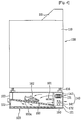
- FIG. 1 illustrates a perspective view of a related art laundry treating machine.
- the related art laundry treating machine is provided with a body 10 which forms an exterior of the laundry treating machine, and a control panel 11 on a front or top of the body.
- the control panel may be provided with a control unit for controlling operation of the laundry treating machine. Therefore, by operating the control unit, the user can treat laundry, such as washing or drying.
- the laundry treating machine may be a washing machine, a dryer, or a washing and drying machine.
- the related art laundry treating machine may be provided with a pedestal 20.
- the body 10 is placed on the pedestal 20.
- the pedestal 20 has a space formed therein in a form of a drawer drawable in a front direction.
- the pedestal serves to support the body 10 and as a box for putting detergent and laundry therein.
- the pedestal 20 fails to have any function for treating the laundry.
- US 2006/0156765 A1 relates to a modular laundry system comprising a first laundry appliance, a second laundry appliance horizontally or vertically arranged relative to the first laundry appliance, and a cabinet module horizontally arranged relative to the first and second laundry appliances.
- US 2006/0103281 A1 relates to a pedestal including a pedestal body for supporting a bottom of a washing machine or a laundry dryer to a height, and at least one coupling means provided both to a side of the washing machine or the laundry dryer and a side of the pedestal body for coupling the washing machine or the laundry dryer with the pedestal body, wherein the coupling means includes a coupling member provided both to a side of the washing machine or the laundry dryer, and a side of the pedestal body under the washing machine or the laundry dryer, and fastening members for fastening the coupling member to the side of the washing machine or the laundry dryer and the side of the pedestal body, respectively.
- an object of the present invention is to provide a supplementary laundry treating machine which enables treatment of small amount of laundry, without operating a relatively larger laundry treating machine, for convenience of use and saving energy.
- Another object of the present invention is to provide a composite laundry treating machine which enables an easy addition of a drying function to a laundry treating machine only with a washing function.
- Another object of the present invention is to provide a composite laundry treating machine which can make easy drying of laundry and the like, such as shoes and caps which have been difficult to dry with a related art drum type dryer.
- Another object of the present invention is to utilize a supplementary space, such as a pedestal for a related art laundry treating machine, as a supplementary laundry treating machine.
- the supplementary laundry treating machine may be installed independent from the laundry treating machine. However, it is preferable that the supplementary laundry treating machine is fixedly secured to one side of a body of the laundry treating machine with joining means, because, as the supplementary laundry treating machine is a machine of treating the laundry in supplementary, it is preferable that the laundry treating machine and the supplementary laundry treating machine are put together at one place for smooth performance of a series of laundry treating steps. Moreover, in view of space utilization, it is preferable that the supplementary laundry treating machine is put together with the laundry treating machine.
- the laundry treating machine may be a washing machine or a dryer, for washing or drying, and a washing and drying machine.
- the laundry treating machine is not limited to this, but may also be a water extractor which performs water extraction only.
- the machine may further include a control unit for controlling operation of the air supply unit, and the control unit is provided to a front of the body.
- the control unit includes a control panel for the user's operation, and only the control panel may be provided to the body of the supplementary laundry treating machine.
- the machine further includes a steam supply unit in the body for selective supply of steam to the space for holding laundry under the control of the control unit.
- the body has a rear wall with an inlet for introduction of the air into the body and an outlet for discharging the air from the body.
- a rear wall of the drawer is in communication with the inlet and the outlet, respectively.
- the machine may further include a rack which divides an inside of the drawer into an upper portion and a lower portion, preferably allowing the upper portion and the lower portion to be in communication with each other for placing the laundry thereon.
- the rack may be tilted, and, preferably, the rack may be tilted down toward the air supply unit.
- the machine further includes an air guide extended from an upper portion of a rear wall of the drawer to an inner side of the drawer for guiding the air to the upper portion of the drawer, for uniform supply of the air throughout the upper portion of the drawer, as well as minimizing interference between in/out air.
- a method for controlling a supplementary laundry treating machine having a space formed therein for holding laundry therein and selective blow of air thereto secured to one side of a laundry treating machine includes the steps of a mode selecting step for the user to select an operation mode, and a drying step for forcible supply of air to the space for holding laundry, with an air temperature and an air supply time period varied with the operation mode the user selects.
- the operation mode includes a refresh mode for refreshing the laundry. If the refresh mode is selected in the mode selecting step, a steam supply step is performed for supplying the steam to the space for holding laundry before the drying step. Of course, the user may select the operation mode of the supplementary laundry treating machine at the control panel on the laundry treating machine.
- the present invention permits the user to wash or dry a large amount of laundry with the laundry treating machine or dry a small amount of laundry with the supplementary laundry treating machine, thereby providing convenience of use and enabling to save energy.
- laundry, such as shoes or a cap, that has been difficult to dry with a related art dry type dryer can be dried, easily.
- the laundry treating machine may be a general washing machine, a dryer, or a washing and drying machine, detailed description of which will be omitted.
- a supplementary laundry treating machine in accordance with a preferred embodiment of the present invention will be described in detail with reference to FIGS. 2 and 3 .
- the supplementary laundry treating machine may have an exterior the same with a laundry treating machine with a pedestal 20.
- the pedestal functions not only as a pedestal, but also as a supplementary laundry treating machine.
- the pedestal includes joining means 130 for fixedly securing the supplementary laundry treating machine to the laundry treating machine.
- the supplementary laundry treating machine is provided to one side of a body 110 of the laundry treating machine. That is, as shown in FIG. 2 , the supplementary laundry treating machine is provided to an underside of the body 110.
- the supplementary laundry treating machine 120 includes a body 121 having a space formed therein for holding the laundry, and joining means 130 at an upper portion thereof for joining the body 110 and the body 121 together.
- the supplementary laundry treating machine 120 supports the body 110 of the laundry treating machine at a bottom thereof.
- the supplementary laundry treating machine 120 may also include leg supporters 125 provided to a top of the supplementary laundry treating machine 120 for supporting sides of lower legs 116, and 117 of the laundry treating machine.
- Each of the leg supporters 125 includes a panel having a first seating hole 126 for seating the washing machine leg 116, and a second seating hole 127 for seating a dryer leg 117, and is fastened to the top of the body 121 of the supplementary laundry treating machine 120 with screws.
- the washing machine and the dryer are modes of the laundry treating machine, wherein a mode is taken as an example, in which the exterior of the washing machine is greater than the exterior of the dryer.
- the leg supporters 125 are fixedly secured to corners of the top of the body 121 of the supplementary laundry treating machine 120 respectively, wherein the first seating hole 126 and the second seating hole 127 of each of the two leg supporters at front corners of the body 121 of the pedestal supplementary laundry treating machine are joined with each other, and the first seating hole 126 and the second seating hole 127 of each of the two leg supporters at rear corners of the body 121 of the supplementary laundry treating machine are not joined with each other, for easy seating of the washing machine legs 116.
- the first seating hole 126 is located on an outer side of the second seating hole 127 with respect to a diagonal line of the underside of the body 110 of the laundry treating machine. This is because, in general, the body of the washing machine is greater than the body of the laundry dryer.
- the joining means 130 includes a joining member 138 provided to sides both of the washing machine or the laundry dryer, and the body 121 of the supplementary laundry treating machine under the washing machine or the laundry dryer, and fastening members 135 for fastening the joining member to the sides of the washing machine or the laundry dryer, and the body 121 of the supplementary laundry treating machine.
- the joining member may include two or more than two joining members 138 each for securing abutted sides of the body 121 of the hexahedral supplementary laundry treating machine, and the body 110 of the hexahedral laundry treating machine, to each other.
- the joining member may also include a third fastening member (not shown) for securing abutted rear sides of the body 121 of the hexahedral supplementary laundry treating machine, and the body 110 of the hexahedral laundry treating machine, to each other.
- a third fastening member (not shown) for securing abutted rear sides of the body 121 of the hexahedral supplementary laundry treating machine, and the body 110 of the hexahedral laundry treating machine, to each other.
- the joining means 130 may be designed to cope with height changes of the washing machine legs 116 or the laundry dryer legs 117.
- the fastening member 135 includes a first fastening member 136 for securing an upper portion of the joining member to a lower portion of a side of the washing machine or the laundry dryer, and a second fastening member 137 for securing a lower portion of the joining member to an upper portion of a side of the pedestal.
- At least one of the first fastening member 136 and the second fastening member 137 may be one having adhesive applied to both sides, for an example, two sided tape.
- At least one of the first fastening member 136 and the second fastening member 137 may be fastening means, such as screws.
- the fastening member is screws
- the upper portion of the joining member has fastening holes formed at fixed intervals.
- the means for joining the body 110 of the laundry treating machine to the body 121 of the supplementary laundry treating machine can be changed in a variety of forms.
- a volume of the body 121 of the supplementary laundry treating machine is smaller than a volume of the body 110 of the laundry treating machine to which the supplementary laundry treating machine is fastened.
- a height of the body of the supplementary laundry treating machine is lower than a height of the body of the laundry treating machine, because the object of the supplementary laundry treating machine in the present invention is to supplement the laundry treating machine.
- At least one of a left/right direction width and a front/rear direction width of the body 121 of the supplementary laundry treating machine is the same or greater than a left/right direction width and a front/rear direction width of the body 110 of the laundry treating machine in a case the supplementary laundry treating machine serves as a pedestal of the laundry treating machine.
- at least one of the left/right direction width and the front/ rear direction width of the body 121 of the supplementary laundry treating machine is the same or smaller than the left/right direction width and the front/rear direction width of the body 110 of the laundry treating machine.
- the supplementary laundry treating machine will be described in detail with reference to FIG. 4 .
- FIG. 4 illustrates a section of a composite laundry treating machine with a supplementary laundry treating machine in accordance with a preferred embodiment of the present invention, schematically.
- the supplementary laundry treating machine 120 may be joined with the body 110 of the laundry treating machine, to construct one composite laundry treating machine 100.
- the laundry treating machine has the laundry introduced to an inside of the body 110, for washing or drying. That is, the laundry treating machine may be a washing machine, a dryer, or a washing and drying machine.
- the composite laundry treating machine 100 includes joining means 130 for securing the body 121 of the supplementary laundry treating machine to one side of the body 110 of the laundry treating machine.
- the joining means 130 is not shown in FIG. 4 .
- the supplementary laundry treating machine 120 has a laundry holding space formed therein for performing a supplementary function for laundry treatment.
- the laundry holding space may have a shape of a drawer 122 which can be drawn in a front direction toward the front of the body 121.
- the supplementary laundry treating machine 120 includes an air supply unit 140 in the body 121 of the supplementary laundry treating machine for forced supply of the air to the space.
- the volume and the height of the body 121 of the supplementary laundry treating machine 120 are smaller and lower than the volume and the height of the body 110 of the laundry treating machine joined with the supplementary laundry treating machine 120.
- the supplementary laundry treating machine 120 includes a steam supply unit 150 in the body 121 for supplying steam to the laundry holding space.
- the steam supply unit 150 has a spray hole (not shown) for spraying the steam to the space through the top or rear of the body.
- control unit 123 operation of the air supply unit 140 and the steam supply unit 150 is controlled by the control unit 123, and it is preferable that the control unit is provided to the front of the body 121.
- the control unit 123 may include a control panel for user's operation.
- control unit 123 can control operation of the supplementary laundry treating machine, separate from the control unit 111 of the laundry treating machine.
- the operation of the supplementary laundry treating machine may be controlled with the control unit 111.
- the control unit 123 may be omitted, or may only function as a display window for displaying an operation state of the supplementary laundry treating machine to the user.
- connection portion (not shown) is formed
- connection portion is insulated against an electric current, and easy to connect, and reliability for the connection is secured.
- connection portion may include connectors (not shown) provided to a lower portion of the laundry treating machine and an upper portion of the supplementary laundry treating machine, respectively.
- the connectors have lines for communication or control connected thereto in a form of harness (not shown).
- the connection portion includes, not only the connectors, but also insulating portions (not shown) for insulation.
- the insulating portions are formed on outside circumferences of the connectors respectively, for performing an insulating function when the connectors are connected
- the insulating portions are formed of insulating material, preferably a material allowing compressed deformation to a certain extent, such as rubber and so on.
- the connector and the insulating portion are formed as a unit, and the insulating portion is formed only on either one of the connectors.
- the laundry treating machine and the supplementary laundry treating machine are pined with the pining means 130 together, wherein the composite laundry treating machine may be designed such that the connectors are automatically connected at the time the laundry treating machine and the supplementary laundry treating machine are joined with the joining means.
- the laundry treating machine and the supplementary laundry treating machine may respectively be provided with wireless communication modules or wired communication system which enable data input/output as means for mutual communication.
- a state of the supplementary laundry treating machine is transmitted to the laundry treating machine by the communication module, such that the user determines the state of the supplementary laundry treating machine through the display window or the like provided to the laundry treating machine, and controls the supplementary laundry treating machine through the control unit 111 of the laundry treating machine.
- Such a control order is transmitted to the supplementary laundry treating machine through the connectors, to control the supplementary laundry treating machine.
- the user may also determine the state of the supplementary laundry treating machine through the display window provided to the supplementary laundry treating machine, and controls the supplementary laundry treating machine through the control unit 111 of the laundry treating machine.
- the air supply unit 140 includes a fan 141 for blowing air, and a heater 142 for heating the air. That is, as the fan 141 is driven, external air is introduced into the drawer 122, and discharged to an outside of the drawer, again. The external air is heated at the heater 142, and is introduced into the drawer 122.
- the heater 142 may have a system selected from a variety of systems, such as electric type or a gas type, in view of nature of the supplementary laundry treating machine, it is preferable that the heater has the electric type, taking a mounting space into account.
- the supplementary laundry treating machine 120 can perform a dry function by using the air supply unit 140.
- the heater 142 has a variable capacity for varying a temperature of the air heated with the heater, because certain fabrics are weak to heat, and rubber of shoes and so on are weak to heat, too.
- the steam supply unit 150 supplies the steam to the drawer.
- the steam is brought into contact with laundry in the drawer, to sterilize and remove creases from the laundry. Therefore, the supplementary laundry treating machine 120 can perform a refresh function by using the steam supply unit 150.
- the supplementary laundry treating machine 120 can perform the refresh function as well as the drying function.
- the body 121 of the supplementary laundry treating machine has an inlet 171 in an upper portion of the rear wall for introduction of the air to the body 121, and an outlet 172 in a lower portion of the rear wall for discharging the air from the body 121.
- the drawer 122 is in communication with the inlet 171 through an upper portion of a rear wall thereof, and the drawer 122 is in communication with the outlet 172 through the upper portion of a rear wall thereof. Accordingly, external air is introduced to the drawer through the upper portion of the body 121 and the upper portion of the drawer, and discharged through the lower portion of the drawer and the lower portion of the rear wall of the body 121.
- the fan 141 that causes an air flow and the heater 142 that heats the air is mounted between the rear wall of the drawer and the rear wall of the body.
- FIG. 4 illustrates a mode (not according to the invention) in which the air is introduced through the upper portion of the drawer and discharged through the lower portion of the drawer. However, opposite to this, the air may be introduced through the lower portion of the drawer and discharged through the upper portion of the drawer.
- the laundry 162 is seated in the drawer 122, and the drawer 122 may have a rack 160 which divides the inside space of the drawer in an upper portion and a lower portion while making the upper portion and the lower portion in communication.
- a rack is provided for smooth discharge of the air supplied to the laundry 162.
- the rack has a plurality of pass through holes 160a. That is, air flows from the upper portion of the drawer to the lower portion of the drawer through the pass through holes.
- the rack may be tilted In this case, it is preferable that the rack is tilted down in a direction of air inlet, for uniform supply of the air to the laundry seated on the rack.
- the drawer has an air guide 161 at the upper portion of the rear wall, for smooth supply of the air up to a front of the drawer and functioning to separate an air introduction flow passage from an air discharge flow passage, which minimizes collision between air being introduced and air being discharged for enhancing efficiency of drying.
- the user draws out the drawer 122, and seats the laundry 162, such as a small amount of fabric or shoes, or a cap, on the rack 160. If the laundry is the fabric, it is preferable that the fabric is spread on the rack.
- the operation mode may be one of a variety of the drying modes, or the refresh mode.
- the variety of the drying modes may be modes of various drying time periods, or various drying temperatures, which are varied with kinds of laundry to be dried
- the drying mode may be set, in which the drying time period is short and the drying temperature is high
- the drying mode may be set, in which the drying time period is long and the drying temperature is low.
- the air is forcibly supplied to the space having the laundry placed therein according to the operation mode the user selects, the air temperature and the air supply time period are varied.
- the operation mode is the refresh mode
- high temperature steam is supplied to the laundry. According to this, refresh of the laundry is made with the steam. That is, deodoring, removal of creases, or sterilizing of laundry is made. Then, air may be supplied as required for drying.
- a supplementary laundry treating machine which can treat small amount of laundry without driving a relatively large sized laundry treating machine permits convenience in use and energy saving.
- a drying function can be added to a laundry treating machine with a washing function only, easily.
- Drying of laundry, such as shoes or cap which has been difficult to dry with a related art drum type dryer can be dried easily, and a space of the pedestal of the related art laundry treating machine, unused in the related art, can be utilized as the supplementary laundry treating machine.
- the present invention can provide a composite laundry treating machine which is convenient to use as the composite laundry treating machine maximizes utilization of space at a low cost.
Landscapes
- Engineering & Computer Science (AREA)
- Textile Engineering (AREA)
- Accessory Of Washing/Drying Machine, Commercial Washing/Drying Machine, Other Washing/Drying Machine (AREA)
Description
- The present invention relates to supplementary laundry treating machines. More specifically, the present invention relates to a supplementary laundry treating machine for a general laundry treating machine, and a composite laundry treating machine having the supplementary laundry treating machine and the laundry treating machine combined therewith (see
US-A-20060156765 ). - In general, the laundry treating machine is a machine which can wash, dry, or wash and dry the laundry. The laundry treating machine can perform a washing or drying function or both the washing and drying functions. Recently, laundry treating machines each having a steam generator are come into wide use, which has a refresh function such as removal of creases, deodoring, removal of static electricity from the laundry.
- In the meantime, according to directions of laundry introduction/taking out, in related art laundry machines, there are front loading type laundry machines and top loading type laundry machines. According to washing systems, there are upright type laundry treating machines in each of which a pulsator or a washing tub rotates, and a horizontal type laundry treating machines in each of which a drum rotates. Typical examples of the horizontal type laundry treating machines are the drum type washing machines or dryers.
- Currently, it is a trend that the laundry treating machines become gradually larger in correspondence to demands of users. That is, sizes of domestic laundry treating machines become larger, gradually.
- In the meantime, of the related art laundry treating machines, there are cases when the washing machines are provided with the drying function. Consequently, if the user needs the drying function, provision of a dryer or a washing and drying machine is required. Accordingly, in order to perform both the washing and drying, an expense of the consumer can not, but increase.
- Moreover, in the laundry treating machine having the drying function, as the laundry treating machine becomes the larger gradually, driving of the large sized dryer even in a case a small amount of laundry is dried is not favorable in view of energy saving. Moreover, drying shoes or clothes with the drum type dryer is difficult. Of course, the shoes may be dried with a rack mounted in the drum, which is kept horizontal regardless of rotation of the drum, for placing the shoes thereon. However, in this case the mounting/dismounting of the rack is cumbersome.
-
FIG. 1 illustrates a perspective view of a related art laundry treating machine. - Referring to
FIG. 1 , the related art laundry treating machine is provided with abody 10 which forms an exterior of the laundry treating machine, and a control panel 11 on a front or top of the body. The control panel may be provided with a control unit for controlling operation of the laundry treating machine. Therefore, by operating the control unit, the user can treat laundry, such as washing or drying. - The laundry treating machine may be a washing machine, a dryer, or a washing and drying machine.
- In the meantime, the related art laundry treating machine may be provided with a
pedestal 20. In this instance, thebody 10 is placed on thepedestal 20. - In general, the
pedestal 20 has a space formed therein in a form of a drawer drawable in a front direction. The pedestal serves to support thebody 10 and as a box for putting detergent and laundry therein. - Consequently, in the related art, the
pedestal 20 fails to have any function for treating the laundry. -
US 2006/0156765 A1 relates to a modular laundry system comprising a first laundry appliance, a second laundry appliance horizontally or vertically arranged relative to the first laundry appliance, and a cabinet module horizontally arranged relative to the first and second laundry appliances. -
US 2006/0103281 A1 relates to a pedestal including a pedestal body for supporting a bottom of a washing machine or a laundry dryer to a height, and at least one coupling means provided both to a side of the washing machine or the laundry dryer and a side of the pedestal body for coupling the washing machine or the laundry dryer with the pedestal body, wherein the coupling means includes a coupling member provided both to a side of the washing machine or the laundry dryer, and a side of the pedestal body under the washing machine or the laundry dryer, and fastening members for fastening the coupling member to the side of the washing machine or the laundry dryer and the side of the pedestal body, respectively. - To solve the problems, an object of the present invention is to provide a supplementary laundry treating machine which enables treatment of small amount of laundry, without operating a relatively larger laundry treating machine, for convenience of use and saving energy.
- Another object of the present invention is to provide a composite laundry treating machine which enables an easy addition of a drying function to a laundry treating machine only with a washing function.
- Another object of the present invention is to provide a composite laundry treating machine which can make easy drying of laundry and the like, such as shoes and caps which have been difficult to dry with a related art drum type dryer.
- Another object of the present invention is to utilize a supplementary space, such as a pedestal for a related art laundry treating machine, as a supplementary laundry treating machine.
- The objects are solved by the features of the independent claim.
- The supplementary laundry treating machine may be installed independent from the laundry treating machine. However, it is preferable that the supplementary laundry treating machine is fixedly secured to one side of a body of the laundry treating machine with joining means, because, as the supplementary laundry treating machine is a machine of treating the laundry in supplementary, it is preferable that the laundry treating machine and the supplementary laundry treating machine are put together at one place for smooth performance of a series of laundry treating steps. Moreover, in view of space utilization, it is preferable that the supplementary laundry treating machine is put together with the laundry treating machine.
- Of course, as a major machine, the laundry treating machine may be a washing machine or a dryer, for washing or drying, and a washing and drying machine. However, the laundry treating machine is not limited to this, but may also be a water extractor which performs water extraction only.
- Preferably, the machine may further include a control unit for controlling operation of the air supply unit, and the control unit is provided to a front of the body. Of course, preferably, the control unit includes a control panel for the user's operation, and only the control panel may be provided to the body of the supplementary laundry treating machine.
- Moreover, preferably, the machine further includes a steam supply unit in the body for selective supply of steam to the space for holding laundry under the control of the control unit.
- The body has a rear wall with an inlet for introduction of the air into the body and an outlet for discharging the air from the body. A rear wall of the drawer is in communication with the inlet and the outlet, respectively.
- The machine may further include a rack which divides an inside of the drawer into an upper portion and a lower portion, preferably allowing the upper portion and the lower portion to be in communication with each other for placing the laundry thereon. The rack may be tilted, and, preferably, the rack may be tilted down toward the air supply unit.
- It is preferable that the machine further includes an air guide extended from an upper portion of a rear wall of the drawer to an inner side of the drawer for guiding the air to the upper portion of the drawer, for uniform supply of the air throughout the upper portion of the drawer, as well as minimizing interference between in/out air.
- Preferably, a method for controlling a supplementary laundry treating machine having a space formed therein for holding laundry therein and selective blow of air thereto secured to one side of a laundry treating machine, includes the steps of a mode selecting step for the user to select an operation mode, and a drying step for forcible supply of air to the space for holding laundry, with an air temperature and an air supply time period varied with the operation mode the user selects.
- The operation mode includes a refresh mode for refreshing the laundry. If the refresh mode is selected in the mode selecting step, a steam supply step is performed for supplying the steam to the space for holding laundry before the drying step. Of course, the user may select the operation mode of the supplementary laundry treating machine at the control panel on the laundry treating machine.
- Thus, the present invention permits the user to wash or dry a large amount of laundry with the laundry treating machine or dry a small amount of laundry with the supplementary laundry treating machine, thereby providing convenience of use and enabling to save energy. Moreover, laundry, such as shoes or a cap, that has been difficult to dry with a related art dry type dryer can be dried, easily.
-
-
FIG. 1 illustrates a perspective view of a related art laundry treating machine with a pedestal; -
FIG. 2 illustrates a perspective view of a composite laundry treating machine with a supplementary laundry treating machine in accordance with a preferred embodiment of the present invention; -
FIG. 3 illustrates an exploded perspective view of the supplementary laundry treating machine inFIG. 2 ; and -
FIG. 4 illustrates a section of a composite laundry treating machine with a supplementary laundry treating machine in accordance with a preferred embodiment of the present invention, schematically. - Reference will now be made in detail to the specific embodiments of the present invention, examples of which are illustrated in the accompanying drawings. Wherever possible, the same reference numbers will be used throughout the drawings to refer to the same or like parts. In the meantime, as the laundry treating machine may be a general washing machine, a dryer, or a washing and drying machine, detailed description of which will be omitted.
- A supplementary laundry treating machine in accordance with a preferred embodiment of the present invention will be described in detail with reference to
FIGS. 2 and 3 . - Referring to
FIG. 1 , the supplementary laundry treating machine may have an exterior the same with a laundry treating machine with apedestal 20. However, as shown inFIGS. 2 and 3 , the pedestal functions not only as a pedestal, but also as a supplementary laundry treating machine. In addition to this, the pedestal includes joining means 130 for fixedly securing the supplementary laundry treating machine to the laundry treating machine. - Referring to
FIG. 2 , the supplementary laundry treating machine is provided to one side of abody 110 of the laundry treating machine. That is, as shown inFIG. 2 , the supplementary laundry treating machine is provided to an underside of thebody 110. - In the meantime, referring to
FIGS. 2 and 3 , the supplementarylaundry treating machine 120 includes abody 121 having a space formed therein for holding the laundry, and joiningmeans 130 at an upper portion thereof for joining thebody 110 and thebody 121 together. The supplementarylaundry treating machine 120 supports thebody 110 of the laundry treating machine at a bottom thereof. - The supplementary
laundry treating machine 120 may also includeleg supporters 125 provided to a top of the supplementarylaundry treating machine 120 for supporting sides oflower legs - Each of the
leg supporters 125 includes a panel having afirst seating hole 126 for seating thewashing machine leg 116, and asecond seating hole 127 for seating adryer leg 117, and is fastened to the top of thebody 121 of the supplementarylaundry treating machine 120 with screws. The washing machine and the dryer are modes of the laundry treating machine, wherein a mode is taken as an example, in which the exterior of the washing machine is greater than the exterior of the dryer. - The
leg supporters 125 are fixedly secured to corners of the top of thebody 121 of the supplementarylaundry treating machine 120 respectively, wherein thefirst seating hole 126 and thesecond seating hole 127 of each of the two leg supporters at front corners of thebody 121 of the pedestal supplementary laundry treating machine are joined with each other, and thefirst seating hole 126 and thesecond seating hole 127 of each of the two leg supporters at rear corners of thebody 121 of the supplementary laundry treating machine are not joined with each other, for easy seating of thewashing machine legs 116. - The
first seating hole 126 is located on an outer side of thesecond seating hole 127 with respect to a diagonal line of the underside of thebody 110 of the laundry treating machine. This is because, in general, the body of the washing machine is greater than the body of the laundry dryer. - The joining means 130 includes a joining
member 138 provided to sides both of the washing machine or the laundry dryer, and thebody 121 of the supplementary laundry treating machine under the washing machine or the laundry dryer, andfastening members 135 for fastening the joining member to the sides of the washing machine or the laundry dryer, and thebody 121 of the supplementary laundry treating machine. - Referring to
FIG. 3 , the joining member may include two or more than two joiningmembers 138 each for securing abutted sides of thebody 121 of the hexahedral supplementary laundry treating machine, and thebody 110 of the hexahedral laundry treating machine, to each other. - In addition to this, the joining member may also include a third fastening member (not shown) for securing abutted rear sides of the
body 121 of the hexahedral supplementary laundry treating machine, and thebody 110 of the hexahedral laundry treating machine, to each other. - In this instance, the joining means 130 may be designed to cope with height changes of the
washing machine legs 116 or thelaundry dryer legs 117. - The
fastening member 135 includes afirst fastening member 136 for securing an upper portion of the joining member to a lower portion of a side of the washing machine or the laundry dryer, and asecond fastening member 137 for securing a lower portion of the joining member to an upper portion of a side of the pedestal. - In this instance, at least one of the
first fastening member 136 and thesecond fastening member 137 may be one having adhesive applied to both sides, for an example, two sided tape. - Different from above, at least one of the
first fastening member 136 and thesecond fastening member 137 may be fastening means, such as screws. - If the fastening member is screws, preferably, the upper portion of the joining member has fastening holes formed at fixed intervals.
- In the meantime, different from above, the means for joining the
body 110 of the laundry treating machine to thebody 121 of the supplementary laundry treating machine can be changed in a variety of forms. - In the present invention, a volume of the
body 121 of the supplementary laundry treating machine is smaller than a volume of thebody 110 of the laundry treating machine to which the supplementary laundry treating machine is fastened. A height of the body of the supplementary laundry treating machine is lower than a height of the body of the laundry treating machine, because the object of the supplementary laundry treating machine in the present invention is to supplement the laundry treating machine. - In view of stability or exterior design of the composite laundry treating machine, it is preferable that at least one of a left/right direction width and a front/rear direction width of the
body 121 of the supplementary laundry treating machine is the same or greater than a left/right direction width and a front/rear direction width of thebody 110 of the laundry treating machine in a case the supplementary laundry treating machine serves as a pedestal of the laundry treating machine. However, in a case the supplementary laundry treating machine is fastened to the top of the laundry treating machine, it is preferable that at least one of the left/right direction width and the front/ rear direction width of thebody 121 of the supplementary laundry treating machine is the same or smaller than the left/right direction width and the front/rear direction width of thebody 110 of the laundry treating machine. - The supplementary laundry treating machine will be described in detail with reference to
FIG. 4 . -
FIG. 4 illustrates a section of a composite laundry treating machine with a supplementary laundry treating machine in accordance with a preferred embodiment of the present invention, schematically. - The supplementary
laundry treating machine 120 may be joined with thebody 110 of the laundry treating machine, to construct one compositelaundry treating machine 100. In this case, the laundry treating machine has the laundry introduced to an inside of thebody 110, for washing or drying. That is, the laundry treating machine may be a washing machine, a dryer, or a washing and drying machine. - The composite
laundry treating machine 100 includes joining means 130 for securing thebody 121 of the supplementary laundry treating machine to one side of thebody 110 of the laundry treating machine. The joining means 130 is not shown inFIG. 4 . - The supplementary
laundry treating machine 120 has a laundry holding space formed therein for performing a supplementary function for laundry treatment. The laundry holding space may have a shape of adrawer 122 which can be drawn in a front direction toward the front of thebody 121. The supplementarylaundry treating machine 120 includes anair supply unit 140 in thebody 121 of the supplementary laundry treating machine for forced supply of the air to the space. - As described before, the volume and the height of the
body 121 of the supplementarylaundry treating machine 120 are smaller and lower than the volume and the height of thebody 110 of the laundry treating machine joined with the supplementarylaundry treating machine 120. - The supplementary
laundry treating machine 120 includes asteam supply unit 150 in thebody 121 for supplying steam to the laundry holding space. Thesteam supply unit 150 has a spray hole (not shown) for spraying the steam to the space through the top or rear of the body. - In this instance, operation of the
air supply unit 140 and thesteam supply unit 150 is controlled by thecontrol unit 123, and it is preferable that the control unit is provided to the front of thebody 121. Thecontrol unit 123 may include a control panel for user's operation. - In the meantime, the
control unit 123 can control operation of the supplementary laundry treating machine, separate from thecontrol unit 111 of the laundry treating machine. - Of course, the operation of the supplementary laundry treating machine may be controlled with the
control unit 111. In this case, thecontrol unit 123 may be omitted, or may only function as a display window for displaying an operation state of the supplementary laundry treating machine to the user. - In a case the supplementary laundry treating machine is controlled with the
control unit 111 of the laundry treating machine, it is required that the laundry treating machine and the supplementary laundry treating machine are wired for control or communication to each other. It is preferable that such a wired portion, i.e., connection portion (not shown) is formed In the meantime, it is required that the connection portion is insulated against an electric current, and easy to connect, and reliability for the connection is secured. - The connection portion may include connectors (not shown) provided to a lower portion of the laundry treating machine and an upper portion of the supplementary laundry treating machine, respectively. The connectors have lines for communication or control connected thereto in a form of harness (not shown).
- The connection portion includes, not only the connectors, but also insulating portions (not shown) for insulation. The insulating portions are formed on outside circumferences of the connectors respectively, for performing an insulating function when the connectors are connected The insulating portions are formed of insulating material, preferably a material allowing compressed deformation to a certain extent, such as rubber and so on.
- In the meantime, it is viable that the connector and the insulating portion are formed as a unit, and the insulating portion is formed only on either one of the connectors.
- As described before, the laundry treating machine and the supplementary laundry treating machine are pined with the pining means 130 together, wherein the composite laundry treating machine may be designed such that the connectors are automatically connected at the time the laundry treating machine and the supplementary laundry treating machine are joined with the joining means.
- In the meantime, the laundry treating machine and the supplementary laundry treating machine may respectively be provided with wireless communication modules or wired communication system which enable data input/output as means for mutual communication.
- Accordingly, a state of the supplementary laundry treating machine is transmitted to the laundry treating machine by the communication module, such that the user determines the state of the supplementary laundry treating machine through the display window or the like provided to the laundry treating machine, and controls the supplementary laundry treating machine through the
control unit 111 of the laundry treating machine. Such a control order is transmitted to the supplementary laundry treating machine through the connectors, to control the supplementary laundry treating machine. - Of course, the user may also determine the state of the supplementary laundry treating machine through the display window provided to the supplementary laundry treating machine, and controls the supplementary laundry treating machine through the
control unit 111 of the laundry treating machine. - In the meantime, the
air supply unit 140 includes afan 141 for blowing air, and aheater 142 for heating the air. That is, as thefan 141 is driven, external air is introduced into thedrawer 122, and discharged to an outside of the drawer, again. The external air is heated at theheater 142, and is introduced into thedrawer 122. - Though the
heater 142 may have a system selected from a variety of systems, such as electric type or a gas type, in view of nature of the supplementary laundry treating machine, it is preferable that the heater has the electric type, taking a mounting space into account. - Accordingly, the supplementary
laundry treating machine 120 can perform a dry function by using theair supply unit 140. It is preferable that theheater 142 has a variable capacity for varying a temperature of the air heated with the heater, because certain fabrics are weak to heat, and rubber of shoes and so on are weak to heat, too. - The
steam supply unit 150 supplies the steam to the drawer. The steam is brought into contact with laundry in the drawer, to sterilize and remove creases from the laundry. Therefore, the supplementarylaundry treating machine 120 can perform a refresh function by using thesteam supply unit 150. Of course, the supplementarylaundry treating machine 120 can perform the refresh function as well as the drying function. - In the meantime, it is preferable that the
body 121 of the supplementary laundry treating machine has aninlet 171 in an upper portion of the rear wall for introduction of the air to thebody 121, and anoutlet 172 in a lower portion of the rear wall for discharging the air from thebody 121. Thedrawer 122 is in communication with theinlet 171 through an upper portion of a rear wall thereof, and thedrawer 122 is in communication with theoutlet 172 through the upper portion of a rear wall thereof. Accordingly, external air is introduced to the drawer through the upper portion of thebody 121 and the upper portion of the drawer, and discharged through the lower portion of the drawer and the lower portion of the rear wall of thebody 121. - The
fan 141 that causes an air flow and theheater 142 that heats the air is mounted between the rear wall of the drawer and the rear wall of the body. -
FIG. 4 illustrates a mode (not according to the invention) in which the air is introduced through the upper portion of the drawer and discharged through the lower portion of the drawer. However, opposite to this, the air may be introduced through the lower portion of the drawer and discharged through the upper portion of the drawer. - In the meantime, referring to
FIG. 4 , thelaundry 162 is seated in thedrawer 122, and thedrawer 122 may have arack 160 which divides the inside space of the drawer in an upper portion and a lower portion while making the upper portion and the lower portion in communication. Such a rack is provided for smooth discharge of the air supplied to thelaundry 162. - It is preferable that the rack has a plurality of pass through
holes 160a. That is, air flows from the upper portion of the drawer to the lower portion of the drawer through the pass through holes. - Moreover, the rack may be tilted In this case, it is preferable that the rack is tilted down in a direction of air inlet, for uniform supply of the air to the laundry seated on the rack.
- It is preferable that the drawer has an
air guide 161 at the upper portion of the rear wall, for smooth supply of the air up to a front of the drawer and functioning to separate an air introduction flow passage from an air discharge flow passage, which minimizes collision between air being introduced and air being discharged for enhancing efficiency of drying. - In the meantime, a variety of drying modes may be performed by using the supplementary laundry dryer of the present invention.
- At first, the user draws out the
drawer 122, and seats thelaundry 162, such as a small amount of fabric or shoes, or a cap, on therack 160. If the laundry is the fabric, it is preferable that the fabric is spread on the rack. - Then, the user selects a desired operation mode at the
control unit 123 having the control panel according to a kind of the laundry. The operation mode may be one of a variety of the drying modes, or the refresh mode. - The variety of the drying modes may be modes of various drying time periods, or various drying temperatures, which are varied with kinds of laundry to be dried For an example, for drying a small amount of fabric of cotton, the drying mode may be set, in which the drying time period is short and the drying temperature is high, and for drying shoes, the drying mode may be set, in which the drying time period is long and the drying temperature is low.
- Though the air is forcibly supplied to the space having the laundry placed therein according to the operation mode the user selects, the air temperature and the air supply time period are varied.
- Moreover, if the operation mode is the refresh mode, high temperature steam is supplied to the laundry. According to this, refresh of the laundry is made with the steam. That is, deodoring, removal of creases, or sterilizing of laundry is made. Then, air may be supplied as required for drying.
- The provision of a supplementary laundry treating machine which can treat small amount of laundry without driving a relatively large sized laundry treating machine permits convenience in use and energy saving.
- A drying function can be added to a laundry treating machine with a washing function only, easily.
- Drying of laundry, such as shoes or cap which has been difficult to dry with a related art drum type dryer can be dried easily, and a space of the pedestal of the related art laundry treating machine, unused in the related art, can be utilized as the supplementary laundry treating machine.
- Thus, the present invention can provide a composite laundry treating machine which is convenient to use as the composite laundry treating machine maximizes utilization of space at a low cost.
Claims (12)
- A composite laundry treating machine comprising:a laundry treating machine (100) for washing or drying laundry held in a body (110);
anda supplementary laundry treating machine (120) located under the laundry treating machine (100),wherein a body (121) of the supplementary laundry treating machine (120) is secured to one side of the body (110) of the laundry treating machine (100) with joining means (130), the body (121) of the supplementary laundry treating machine (120) having a volume and a height smaller and lower than a volume and a height of the laundry treating machine (100) respectively, and a space for holding laundry therein having a shape of a drawer (122) which can be drawn forward from the front of the body (121) of the supplementary laundry treating machine (120),characterized bythe body (121) of the supplementary laundry treating machine (120) including an air supply unit (140) provided therein for supplying air to the space for holding laundry; wherein the air supply unit (140) includes a fan (141) for blowing air, and a heater (142) for heating the air being blown by the fan (141), the fan (141) and the heater (142) being mounted between a rear wall of the drawer (122) and the rear wall of the body (121) of the supplementary laundry treating machine; andwherein the rear wall of the body of the supplementary laundry treating machine is provided with an inlet (171) for introduction of the air into the body (121) and an outlet (172) for discharging the air from the body (121), and a rear wall of the drawer (122) is in communication with the inlet (171) and the outlet (172), respectively. - The machine as claimed in claim 1, further comprising
a control unit (123) provided to a front of the body (121) of the supplementary laundry machine (120) for controlling operation of the air supply unit (140). - The machine as claimed in claim 1, further comprising a steam supply unit (140) in the body (121) of the supplementary laundry treating machine (120) for selectively supplying steam to the space for holding laundry under the control of the control unit (123).
- The machine as claimed in claim 3, wherein the air supply unit (140) and the steam supply unit (150) are provided between the rear wall of the drawer (122) and the rear wall of the body (121).
- The machine as claimed in claim 1, further comprising a shelf (160) which divides an inside of the drawer (122) into an upper portion and a lower portion while allowing the upper portion and the lower portion to be in communication with each other for placing the laundry thereon.
- The machine as claimed in claim 5, wherein the shelf is tilted down toward the air supply unit (140).
- The machine as claimed in claim 1, further comprising an air guide (161) extended to an inner side of the drawer (122) for guiding the air.
- The machine as claimed in claim 1, further comprising a control unit (123) for controlling both operation of the laundry treating machine (100), and operation of the supplementary laundry treating machine (120).
- The machine as claimed in claim 8, wherein the control unit (123) is provided to the body (121) of the laundry treating machine.
- The machine as claimed in claim 9, further comprising connection means for communication or control between the laundry treating machine and the supplementary laundry treating machine,
wherein the connection means includes connectors for connecting various kinds of cable between the laundry treating machine and the supplementary laundry treating machine for communication or control therebetween, wherein, if the laundry treating machine and the supplementary laundry treating machine are joined with the joining means, the connector is connected, automatically. - The machine as claimed in claim 8, further comprising communication means for data communication between the laundry treating machine and the supplementary laundry treating machine,
wherein the communication means comprises communication modules provided to the laundry treating machine and the supplementary laundry treating machine respectively, for enabling wire or wireless communication. - The machine as claimed in claim 1, wherein the joining means (130) includes;
a plurality of joining members each provided to sides both of the laundry treating machine (100), and the supplementary laundry treating machine (120), and
fastening members for fastening the joining member to the sides both of the laundry treating machine, and the supplementary laundry treating machine,
wherein the fastening member includes;
a first fastening member (136) for fastening an upper portion of the joining member (130) to the side of the laundry treating machine, and
a second fastening member (137) for fastening a lower portion of the joining member (130) to the side of the supplementary laundry treating machine (120).
Applications Claiming Priority (3)
| Application Number | Priority Date | Filing Date | Title |
|---|---|---|---|
| KR1020060069866A KR100755865B1 (en) | 2006-07-25 | 2006-07-25 | Multiple laundry treating machine |
| KR1020060069863A KR100710315B1 (en) | 2006-07-25 | 2006-07-25 | Auxiliary laundry treating machine and multiple laundry treating machine including the same |
| PCT/KR2007/003559 WO2008013395A2 (en) | 2006-07-25 | 2007-07-25 | Auxiliary laundry treating machine and multiple laundry treating machine including the same |
Publications (3)
| Publication Number | Publication Date |
|---|---|
| EP2057313A2 EP2057313A2 (en) | 2009-05-13 |
| EP2057313A4 EP2057313A4 (en) | 2013-09-11 |
| EP2057313B1 true EP2057313B1 (en) | 2017-03-01 |
Family
ID=38981900
Family Applications (1)
| Application Number | Title | Priority Date | Filing Date |
|---|---|---|---|
| EP07793231.7A Active EP2057313B1 (en) | 2006-07-25 | 2007-07-25 | Auxiliary laundry treating machine and multiple laundry treating machine including the same |
Country Status (8)
| Country | Link |
|---|---|
| US (1) | US20090235551A1 (en) |
| EP (1) | EP2057313B1 (en) |
| AU (1) | AU2007277583B2 (en) |
| BR (1) | BRPI0714946B1 (en) |
| CA (1) | CA2659186C (en) |
| ES (1) | ES2625870T3 (en) |
| RU (1) | RU2401341C1 (en) |
| WO (1) | WO2008013395A2 (en) |
Families Citing this family (12)
| Publication number | Priority date | Publication date | Assignee | Title |
|---|---|---|---|---|
| US7913419B2 (en) * | 2005-12-30 | 2011-03-29 | Whirlpool Corporation | Non-tumble clothes dryer |
| KR101265622B1 (en) * | 2006-08-22 | 2013-05-22 | 엘지전자 주식회사 | Pedestal Drying Machine |
| KR101608760B1 (en) | 2008-04-30 | 2016-04-04 | 엘지전자 주식회사 | Laundry machine |
| ATE533881T1 (en) | 2008-04-30 | 2011-12-15 | Lg Electronics Inc | WASHING MACHINE |
| ES2374767T3 (en) | 2008-04-30 | 2012-02-21 | Lg Electronics Inc. | WASHING MACHINE. |
| KR101012388B1 (en) * | 2009-02-23 | 2011-02-09 | 엘지전자 주식회사 | Combined laundry treating machine |
| KR101887455B1 (en) * | 2012-01-13 | 2018-08-10 | 엘지전자 주식회사 | Dryer |
| DE102014203071B4 (en) | 2013-02-28 | 2018-11-29 | Lg Electronics Inc. | Laundry treatment device |
| KR102486960B1 (en) * | 2015-06-30 | 2023-01-11 | 엘지전자 주식회사 | Laundry Treating Apparatus |
| KR101894883B1 (en) * | 2017-06-02 | 2018-10-04 | 엘지전자 주식회사 | Laundry Treating Apparatus |
| EP3868938B1 (en) * | 2020-02-19 | 2024-05-01 | LG Electronics Inc. | Laundry treating apparatus |
| EP3868939A1 (en) * | 2020-02-19 | 2021-08-25 | LG Electronics Inc. | Laundry treating apparatus |
Family Cites Families (13)
| Publication number | Priority date | Publication date | Assignee | Title |
|---|---|---|---|---|
| JPS54108060A (en) * | 1978-02-10 | 1979-08-24 | Matsushita Electric Ind Co Ltd | Clothes dryer |
| US5666743A (en) * | 1996-02-26 | 1997-09-16 | Dawson; Bonnie D. | Apparel drying and deodorizing system |
| US20020017117A1 (en) * | 2000-07-25 | 2002-02-14 | Sunshine Richard A. | Integrated laundry center |
| US7624600B2 (en) * | 2000-07-25 | 2009-12-01 | Whirlpool Corporation | Modular laundry system with horizontally arranged cabinet module |
| US6973740B2 (en) * | 2003-01-14 | 2005-12-13 | Whirlpool Corporation | Stationary clothes drying apparatus |
| US20040245899A1 (en) * | 2003-06-05 | 2004-12-09 | Cho Han Ki | Washing machine pedestal |
| WO2005026427A1 (en) * | 2003-09-08 | 2005-03-24 | Casella Anthony J | Drying apparatus, system and kit |
| KR20060005849A (en) * | 2004-07-14 | 2006-01-18 | 삼성전자주식회사 | Domestic appliances having a stacking structure |
| US7306386B2 (en) * | 2004-07-29 | 2007-12-11 | Zih Corp. | Docking station and associated method for docking a portable printer |
| KR100595263B1 (en) * | 2004-11-10 | 2006-07-03 | 엘지전자 주식회사 | operating method of Refresh Mode in washing device |
| US20060150439A1 (en) * | 2005-01-12 | 2006-07-13 | Latack Thomas A | Clothes dryer drive |
| US7913419B2 (en) * | 2005-12-30 | 2011-03-29 | Whirlpool Corporation | Non-tumble clothes dryer |
| JP4328347B2 (en) * | 2006-11-10 | 2009-09-09 | ホシデン株式会社 | Microphone and its mounting structure |
-
2007
- 2007-07-25 ES ES07793231.7T patent/ES2625870T3/en active Active
- 2007-07-25 CA CA2659186A patent/CA2659186C/en not_active Expired - Fee Related
- 2007-07-25 US US12/309,613 patent/US20090235551A1/en not_active Abandoned
- 2007-07-25 EP EP07793231.7A patent/EP2057313B1/en active Active
- 2007-07-25 AU AU2007277583A patent/AU2007277583B2/en not_active Ceased
- 2007-07-25 BR BRPI0714946-8A patent/BRPI0714946B1/en not_active IP Right Cessation
- 2007-07-25 WO PCT/KR2007/003559 patent/WO2008013395A2/en active Application Filing
- 2007-07-25 RU RU2009106462/12A patent/RU2401341C1/en not_active IP Right Cessation
Non-Patent Citations (1)
| Title |
|---|
| None * |
Also Published As
| Publication number | Publication date |
|---|---|
| WO2008013395A3 (en) | 2008-06-19 |
| ES2625870T3 (en) | 2017-07-20 |
| RU2009106462A (en) | 2010-08-27 |
| BRPI0714946B1 (en) | 2018-02-06 |
| AU2007277583B2 (en) | 2011-10-27 |
| US20090235551A1 (en) | 2009-09-24 |
| EP2057313A4 (en) | 2013-09-11 |
| WO2008013395A2 (en) | 2008-01-31 |
| EP2057313A2 (en) | 2009-05-13 |
| AU2007277583A1 (en) | 2008-01-31 |
| CA2659186C (en) | 2012-05-22 |
| RU2401341C1 (en) | 2010-10-10 |
| CA2659186A1 (en) | 2008-01-31 |
| BRPI0714946A2 (en) | 2013-05-21 |
Similar Documents
| Publication | Publication Date | Title |
|---|---|---|
| EP2057313B1 (en) | Auxiliary laundry treating machine and multiple laundry treating machine including the same | |
| US8789288B2 (en) | Pedestal drying machine using PTC heater | |
| EP2064382B1 (en) | Multiple laundry treating machine | |
| EP1895039B1 (en) | Auxiliary dryer and complex laundry machine including the same | |
| EP2134895B1 (en) | Cloth treating apparatus | |
| EP2134894B1 (en) | Cloth treating apparatus | |
| CN100570039C (en) | Combined laundry machine | |
| CA2661213C (en) | Multiple laundry machine | |
| KR100710315B1 (en) | Auxiliary laundry treating machine and multiple laundry treating machine including the same | |
| US8769997B2 (en) | Laundry machine | |
| US20090277036A1 (en) | Pedestal drying machine | |
| KR100774213B1 (en) | Multiple laundry treating machine | |
| KR100774211B1 (en) | Multiple laundry treating machine | |
| KR100774212B1 (en) | Multiple laundry treating machine | |
| KR100755865B1 (en) | Multiple laundry treating machine | |
| KR100767696B1 (en) | Multiple laundry treating machine |
Legal Events
| Date | Code | Title | Description |
|---|---|---|---|
| PUAI | Public reference made under article 153(3) epc to a published international application that has entered the european phase |
Free format text: ORIGINAL CODE: 0009012 |
|
| 17P | Request for examination filed |
Effective date: 20090225 |
|
| AK | Designated contracting states |
Kind code of ref document: A2 Designated state(s): AT BE BG CH CY CZ DE DK EE ES FI FR GB GR HU IE IS IT LI LT LU LV MC MT NL PL PT RO SE SI SK TR |
|
| AX | Request for extension of the european patent |
Extension state: AL BA HR MK RS |
|
| DAX | Request for extension of the european patent (deleted) | ||
| A4 | Supplementary search report drawn up and despatched |
Effective date: 20130813 |
|
| RIC1 | Information provided on ipc code assigned before grant |
Ipc: D06F 58/10 20060101AFI20130807BHEP Ipc: D06F 73/02 20060101ALI20130807BHEP |
|
| GRAP | Despatch of communication of intention to grant a patent |
Free format text: ORIGINAL CODE: EPIDOSNIGR1 |
|
| INTG | Intention to grant announced |
Effective date: 20160916 |
|
| RAP1 | Party data changed (applicant data changed or rights of an application transferred) |
Owner name: LG ELECTRONICS INC. |
|
| GRAS | Grant fee paid |
Free format text: ORIGINAL CODE: EPIDOSNIGR3 |
|
| GRAA | (expected) grant |
Free format text: ORIGINAL CODE: 0009210 |
|
| AK | Designated contracting states |
Kind code of ref document: B1 Designated state(s): AT BE BG CH CY CZ DE DK EE ES FI FR GB GR HU IE IS IT LI LT LU LV MC MT NL PL PT RO SE SI SK TR |
|
| REG | Reference to a national code |
Ref country code: GB Ref legal event code: FG4D |
|
| REG | Reference to a national code |
Ref country code: CH Ref legal event code: EP Ref country code: AT Ref legal event code: REF Ref document number: 871475 Country of ref document: AT Kind code of ref document: T Effective date: 20170315 |
|
| REG | Reference to a national code |
Ref country code: IE Ref legal event code: FG4D Ref country code: NL Ref legal event code: FP |
|
| REG | Reference to a national code |
Ref country code: DE Ref legal event code: R096 Ref document number: 602007049975 Country of ref document: DE |
|
| REG | Reference to a national code |
Ref country code: FR Ref legal event code: PLFP Year of fee payment: 11 |
|
| REG | Reference to a national code |
Ref country code: LT Ref legal event code: MG4D |
|
| REG | Reference to a national code |
Ref country code: AT Ref legal event code: MK05 Ref document number: 871475 Country of ref document: AT Kind code of ref document: T Effective date: 20170301 |
|
| REG | Reference to a national code |
Ref country code: ES Ref legal event code: FG2A Ref document number: 2625870 Country of ref document: ES Kind code of ref document: T3 Effective date: 20170720 |
|
| PG25 | Lapsed in a contracting state [announced via postgrant information from national office to epo] |
Ref country code: LT Free format text: LAPSE BECAUSE OF FAILURE TO SUBMIT A TRANSLATION OF THE DESCRIPTION OR TO PAY THE FEE WITHIN THE PRESCRIBED TIME-LIMIT Effective date: 20170301 Ref country code: GR Free format text: LAPSE BECAUSE OF FAILURE TO SUBMIT A TRANSLATION OF THE DESCRIPTION OR TO PAY THE FEE WITHIN THE PRESCRIBED TIME-LIMIT Effective date: 20170602 Ref country code: FI Free format text: LAPSE BECAUSE OF FAILURE TO SUBMIT A TRANSLATION OF THE DESCRIPTION OR TO PAY THE FEE WITHIN THE PRESCRIBED TIME-LIMIT Effective date: 20170301 |
|
| PG25 | Lapsed in a contracting state [announced via postgrant information from national office to epo] |
Ref country code: LV Free format text: LAPSE BECAUSE OF FAILURE TO SUBMIT A TRANSLATION OF THE DESCRIPTION OR TO PAY THE FEE WITHIN THE PRESCRIBED TIME-LIMIT Effective date: 20170301 Ref country code: AT Free format text: LAPSE BECAUSE OF FAILURE TO SUBMIT A TRANSLATION OF THE DESCRIPTION OR TO PAY THE FEE WITHIN THE PRESCRIBED TIME-LIMIT Effective date: 20170301 Ref country code: BG Free format text: LAPSE BECAUSE OF FAILURE TO SUBMIT A TRANSLATION OF THE DESCRIPTION OR TO PAY THE FEE WITHIN THE PRESCRIBED TIME-LIMIT Effective date: 20170601 Ref country code: SE Free format text: LAPSE BECAUSE OF FAILURE TO SUBMIT A TRANSLATION OF THE DESCRIPTION OR TO PAY THE FEE WITHIN THE PRESCRIBED TIME-LIMIT Effective date: 20170301 |
|
| PG25 | Lapsed in a contracting state [announced via postgrant information from national office to epo] |
Ref country code: SK Free format text: LAPSE BECAUSE OF FAILURE TO SUBMIT A TRANSLATION OF THE DESCRIPTION OR TO PAY THE FEE WITHIN THE PRESCRIBED TIME-LIMIT Effective date: 20170301 Ref country code: CZ Free format text: LAPSE BECAUSE OF FAILURE TO SUBMIT A TRANSLATION OF THE DESCRIPTION OR TO PAY THE FEE WITHIN THE PRESCRIBED TIME-LIMIT Effective date: 20170301 Ref country code: RO Free format text: LAPSE BECAUSE OF FAILURE TO SUBMIT A TRANSLATION OF THE DESCRIPTION OR TO PAY THE FEE WITHIN THE PRESCRIBED TIME-LIMIT Effective date: 20170301 Ref country code: EE Free format text: LAPSE BECAUSE OF FAILURE TO SUBMIT A TRANSLATION OF THE DESCRIPTION OR TO PAY THE FEE WITHIN THE PRESCRIBED TIME-LIMIT Effective date: 20170301 |
|
| PG25 | Lapsed in a contracting state [announced via postgrant information from national office to epo] |
Ref country code: PL Free format text: LAPSE BECAUSE OF FAILURE TO SUBMIT A TRANSLATION OF THE DESCRIPTION OR TO PAY THE FEE WITHIN THE PRESCRIBED TIME-LIMIT Effective date: 20170301 Ref country code: IS Free format text: LAPSE BECAUSE OF FAILURE TO SUBMIT A TRANSLATION OF THE DESCRIPTION OR TO PAY THE FEE WITHIN THE PRESCRIBED TIME-LIMIT Effective date: 20170701 Ref country code: PT Free format text: LAPSE BECAUSE OF FAILURE TO SUBMIT A TRANSLATION OF THE DESCRIPTION OR TO PAY THE FEE WITHIN THE PRESCRIBED TIME-LIMIT Effective date: 20170703 |
|
| REG | Reference to a national code |
Ref country code: DE Ref legal event code: R097 Ref document number: 602007049975 Country of ref document: DE |
|
| PLBE | No opposition filed within time limit |
Free format text: ORIGINAL CODE: 0009261 |
|
| STAA | Information on the status of an ep patent application or granted ep patent |
Free format text: STATUS: NO OPPOSITION FILED WITHIN TIME LIMIT |
|
| PG25 | Lapsed in a contracting state [announced via postgrant information from national office to epo] |
Ref country code: DK Free format text: LAPSE BECAUSE OF FAILURE TO SUBMIT A TRANSLATION OF THE DESCRIPTION OR TO PAY THE FEE WITHIN THE PRESCRIBED TIME-LIMIT Effective date: 20170301 |
|
| 26N | No opposition filed |
Effective date: 20171204 |
|
| PG25 | Lapsed in a contracting state [announced via postgrant information from national office to epo] |
Ref country code: SI Free format text: LAPSE BECAUSE OF FAILURE TO SUBMIT A TRANSLATION OF THE DESCRIPTION OR TO PAY THE FEE WITHIN THE PRESCRIBED TIME-LIMIT Effective date: 20170301 |
|
| REG | Reference to a national code |
Ref country code: CH Ref legal event code: PL |
|
| REG | Reference to a national code |
Ref country code: IE Ref legal event code: MM4A |
|
| PG25 | Lapsed in a contracting state [announced via postgrant information from national office to epo] |
Ref country code: CH Free format text: LAPSE BECAUSE OF NON-PAYMENT OF DUE FEES Effective date: 20170731 Ref country code: IE Free format text: LAPSE BECAUSE OF NON-PAYMENT OF DUE FEES Effective date: 20170725 Ref country code: LI Free format text: LAPSE BECAUSE OF NON-PAYMENT OF DUE FEES Effective date: 20170731 |
|
| REG | Reference to a national code |
Ref country code: FR Ref legal event code: PLFP Year of fee payment: 12 |
|
| REG | Reference to a national code |
Ref country code: BE Ref legal event code: MM Effective date: 20170731 |
|
| PG25 | Lapsed in a contracting state [announced via postgrant information from national office to epo] |
Ref country code: LU Free format text: LAPSE BECAUSE OF NON-PAYMENT OF DUE FEES Effective date: 20170725 |
|
| PG25 | Lapsed in a contracting state [announced via postgrant information from national office to epo] |
Ref country code: BE Free format text: LAPSE BECAUSE OF NON-PAYMENT OF DUE FEES Effective date: 20170731 |
|
| PG25 | Lapsed in a contracting state [announced via postgrant information from national office to epo] |
Ref country code: MT Free format text: LAPSE BECAUSE OF NON-PAYMENT OF DUE FEES Effective date: 20170725 |
|
| PG25 | Lapsed in a contracting state [announced via postgrant information from national office to epo] |
Ref country code: HU Free format text: LAPSE BECAUSE OF FAILURE TO SUBMIT A TRANSLATION OF THE DESCRIPTION OR TO PAY THE FEE WITHIN THE PRESCRIBED TIME-LIMIT; INVALID AB INITIO Effective date: 20070725 Ref country code: MC Free format text: LAPSE BECAUSE OF FAILURE TO SUBMIT A TRANSLATION OF THE DESCRIPTION OR TO PAY THE FEE WITHIN THE PRESCRIBED TIME-LIMIT Effective date: 20170301 |
|
| PG25 | Lapsed in a contracting state [announced via postgrant information from national office to epo] |
Ref country code: CY Free format text: LAPSE BECAUSE OF NON-PAYMENT OF DUE FEES Effective date: 20170301 |
|
| GBPC | Gb: european patent ceased through non-payment of renewal fee |
Effective date: 20190725 |
|
| PG25 | Lapsed in a contracting state [announced via postgrant information from national office to epo] |
Ref country code: GB Free format text: LAPSE BECAUSE OF NON-PAYMENT OF DUE FEES Effective date: 20190725 |
|
| REG | Reference to a national code |
Ref country code: ES Ref legal event code: FD2A Effective date: 20201201 |
|
| PG25 | Lapsed in a contracting state [announced via postgrant information from national office to epo] |
Ref country code: ES Free format text: LAPSE BECAUSE OF NON-PAYMENT OF DUE FEES Effective date: 20190726 |
|
| PGFP | Annual fee paid to national office [announced via postgrant information from national office to epo] |
Ref country code: NL Payment date: 20220603 Year of fee payment: 16 Ref country code: IT Payment date: 20220606 Year of fee payment: 16 |
|
| PGFP | Annual fee paid to national office [announced via postgrant information from national office to epo] |
Ref country code: TR Payment date: 20220603 Year of fee payment: 16 |
|
| PGFP | Annual fee paid to national office [announced via postgrant information from national office to epo] |
Ref country code: FR Payment date: 20220607 Year of fee payment: 16 |
|
| PGFP | Annual fee paid to national office [announced via postgrant information from national office to epo] |
Ref country code: DE Payment date: 20220603 Year of fee payment: 16 |
|
| P01 | Opt-out of the competence of the unified patent court (upc) registered |
Effective date: 20230524 |
|
| REG | Reference to a national code |
Ref country code: DE Ref legal event code: R119 Ref document number: 602007049975 Country of ref document: DE |
|
| REG | Reference to a national code |
Ref country code: NL Ref legal event code: MM Effective date: 20230801 |
|
| PG25 | Lapsed in a contracting state [announced via postgrant information from national office to epo] |
Ref country code: NL Free format text: LAPSE BECAUSE OF NON-PAYMENT OF DUE FEES Effective date: 20230801 |
|
| PG25 | Lapsed in a contracting state [announced via postgrant information from national office to epo] |
Ref country code: NL Free format text: LAPSE BECAUSE OF NON-PAYMENT OF DUE FEES Effective date: 20230801 Ref country code: DE Free format text: LAPSE BECAUSE OF NON-PAYMENT OF DUE FEES Effective date: 20240201 |