EP2053424A1 - Target detecting device, target detecting method, and target detecting program - Google Patents
Target detecting device, target detecting method, and target detecting program Download PDFInfo
- Publication number
- EP2053424A1 EP2053424A1 EP08018380A EP08018380A EP2053424A1 EP 2053424 A1 EP2053424 A1 EP 2053424A1 EP 08018380 A EP08018380 A EP 08018380A EP 08018380 A EP08018380 A EP 08018380A EP 2053424 A1 EP2053424 A1 EP 2053424A1
- Authority
- EP
- European Patent Office
- Prior art keywords
- detected
- target
- tracking
- laser
- stopped
- Prior art date
- Legal status (The legal status is an assumption and is not a legal conclusion. Google has not performed a legal analysis and makes no representation as to the accuracy of the status listed.)
- Granted
Links
- 238000000034 method Methods 0.000 title claims abstract description 24
- 238000013459 approach Methods 0.000 claims abstract description 9
- 238000001514 detection method Methods 0.000 description 27
- 230000037237 body shape Effects 0.000 description 11
- 238000010586 diagram Methods 0.000 description 11
- 238000012545 processing Methods 0.000 description 11
- 241001465754 Metazoa Species 0.000 description 10
- 238000012544 monitoring process Methods 0.000 description 4
- 238000006243 chemical reaction Methods 0.000 description 2
- 238000005286 illumination Methods 0.000 description 2
- 238000012986 modification Methods 0.000 description 2
- 230000004048 modification Effects 0.000 description 2
- 230000000694 effects Effects 0.000 description 1
- 230000010365 information processing Effects 0.000 description 1
- 230000003287 optical effect Effects 0.000 description 1
- 230000002265 prevention Effects 0.000 description 1
Images


Classifications
-
- G—PHYSICS
- G01—MEASURING; TESTING
- G01S—RADIO DIRECTION-FINDING; RADIO NAVIGATION; DETERMINING DISTANCE OR VELOCITY BY USE OF RADIO WAVES; LOCATING OR PRESENCE-DETECTING BY USE OF THE REFLECTION OR RERADIATION OF RADIO WAVES; ANALOGOUS ARRANGEMENTS USING OTHER WAVES
- G01S17/00—Systems using the reflection or reradiation of electromagnetic waves other than radio waves, e.g. lidar systems
- G01S17/02—Systems using the reflection of electromagnetic waves other than radio waves
- G01S17/04—Systems determining the presence of a target
-
- G—PHYSICS
- G01—MEASURING; TESTING
- G01S—RADIO DIRECTION-FINDING; RADIO NAVIGATION; DETERMINING DISTANCE OR VELOCITY BY USE OF RADIO WAVES; LOCATING OR PRESENCE-DETECTING BY USE OF THE REFLECTION OR RERADIATION OF RADIO WAVES; ANALOGOUS ARRANGEMENTS USING OTHER WAVES
- G01S17/00—Systems using the reflection or reradiation of electromagnetic waves other than radio waves, e.g. lidar systems
- G01S17/66—Tracking systems using electromagnetic waves other than radio waves
-
- G—PHYSICS
- G01—MEASURING; TESTING
- G01S—RADIO DIRECTION-FINDING; RADIO NAVIGATION; DETERMINING DISTANCE OR VELOCITY BY USE OF RADIO WAVES; LOCATING OR PRESENCE-DETECTING BY USE OF THE REFLECTION OR RERADIATION OF RADIO WAVES; ANALOGOUS ARRANGEMENTS USING OTHER WAVES
- G01S7/00—Details of systems according to groups G01S13/00, G01S15/00, G01S17/00
- G01S7/48—Details of systems according to groups G01S13/00, G01S15/00, G01S17/00 of systems according to group G01S17/00
- G01S7/4802—Details of systems according to groups G01S13/00, G01S15/00, G01S17/00 of systems according to group G01S17/00 using analysis of echo signal for target characterisation; Target signature; Target cross-section
-
- G—PHYSICS
- G08—SIGNALLING
- G08B—SIGNALLING OR CALLING SYSTEMS; ORDER TELEGRAPHS; ALARM SYSTEMS
- G08B13/00—Burglar, theft or intruder alarms
- G08B13/18—Actuation by interference with heat, light, or radiation of shorter wavelength; Actuation by intruding sources of heat, light, or radiation of shorter wavelength
- G08B13/181—Actuation by interference with heat, light, or radiation of shorter wavelength; Actuation by intruding sources of heat, light, or radiation of shorter wavelength using active radiation detection systems
- G08B13/183—Actuation by interference with heat, light, or radiation of shorter wavelength; Actuation by intruding sources of heat, light, or radiation of shorter wavelength using active radiation detection systems by interruption of a radiation beam or barrier
- G08B13/184—Actuation by interference with heat, light, or radiation of shorter wavelength; Actuation by intruding sources of heat, light, or radiation of shorter wavelength using active radiation detection systems by interruption of a radiation beam or barrier using radiation reflectors
Definitions
- the present invention relates to a target detecting device, a target detecting method, and a target detecting program, which detect a target. More specifically, the present invention relates to a target detecting device, a target detecting method, and a target detecting program, which detect a target by emitting and receiving a laser beam.
- a burglarproof system typically has a detecting device which detects a human who intrudes into a predetermined guarding area (hereinafter, referred to as an "intruder"), and an alarm generating device which generates an alarm based on a detected result.
- the detecting device is an infrared sensor or a laser sensor, which detects the intruder using a light beam.
- the alarm device permits lighting or flashing of an illuminating lamp and sounding of an alarm buzzer or a siren.
- the alarm device transmits an alarm signal to a facility to be guarded or a remote place.
- the burglarproof system further has an image displaying device which images the guarding area to display its image.
- the laser sensor uses a laser beam as the detecting device.
- the laser sensor has a laser pulse generator (for example, including a laser diode), and a photodetector (for example, including an avalanche photodiode).
- the laser pulse generator generates a laser pulse wave.
- the photodetector detects a reflection light reflected from the target. Flight time, that is, reflection time is computed to measure a distance from the laser sensor to the target.
- a scan mechanism portion may further be provided to rotate a laser optical axis, and in this case, two-dimensional distance information can be obtained. Therefore, a wide monitoring area can be set (see Patent No. 3011121).
- the detecting device used for the burglarproof system need to be set so as to reliably detect a human and not to detect a small animal such as a dog or a cat.
- the detecting device often detects the small animal as the human to output a human body detecting signal, resulting in lowering of the reliability of the burglarproof system.
- the difference in height between the human and the small animal is used to install the laser sensor horizontally at about the height of a waist of an adult. In this case, the human is detected and the small animal is not detected.
- the laser sensor is installed horizontally in a low position and an obstruction of about the height of the human exists between the laser sensor and the guarding area, it is difficult to avoid occurrence of a plurality of undetectable areas in the guarding area.
- An object of the present invention is to reduce the misdetection while maintaining a wide detecting range in a target detecting technique using a laser sensor.
- a target detecting device is a device for detecting a target by emitting and receiving a laser beam and has a laser emitting and receiving portion, a distance information obtaining portion, a tracking stop determining portion, and a target determining portion.
- the laser emitting and receiving portion can emit the laser beam diagonally downward from an installing position.
- the distance information obtaining portion can obtain distance information from the laser emitting and receiving portion to an object to be detected.
- the tracking stop determining portion when the object to be detected approaches the laser emitting and receiving portion, can determine whether the tracking of the object to be detected is stopped or not.
- the target determining portion when the tracking of the object to be detected is stopped, can determine whether the object to be detected is the target or a non-target based on distance information immediately before the tracking of the object to be detected is stopped.
- the laser beam is emitted diagonally downward from the laser emitting and receiving portion so that a wide detecting range can be maintained.
- the tracking of the object to be detected is stopped, it can be determined whether the object to be detected is the target or the non-target based on the distance information immediately before the tracking of the object to be detected is stopped. Therefore, the misdetection can be reduced while maintaining a wide detecting range.
- the target detecting device in a second aspect of the present invention, the target detecting device according to the first aspect of the present invention, wherein the target determining portion, if the distance information immediately before the tracking of the object to be detected is stopped shows a predetermined length or above, determines that the object to be detected is the target, and if the distance information immediately before the tracking of the object to be detected is stopped shows less than the predetermined length, determines that the object to be detected is the non-target.
- the target detecting device it is determined that the object to be detected of the predetermined height or above is the target and that the object to be detected of less than the predetermined height is the non-target.
- the target detecting device further includes a scan mechanism portion.
- the scan mechanism can change the direction of the laser beam emitted from the laser emitting and receiving portion.
- the direction of the laser beam emitted from the laser emitting and receiving portion can be changed by the scan mechanism portion. Therefore, the angle of the laser emission light, for example, is changed to detect the target in a two-dimensional area.
- a target detecting method for detecting a target by emitting a laser beam diagonally downward from an installing position of a laser emitting and receiving portion includes the following steps.
- the laser beam is emitted diagonally downward from the laser emitting and receiving portion so that a wide detecting range can be maintained.
- the tracking of the object to be detected is stopped, it can be determined whether the object to be detected is the target or the non-target based on the distance information immediately before the tracking of the object to be detected is stopped. Therefore, the misdetection can be reduced while maintaining a wide detecting range.
- the target detecting method according to the fourth aspect of the present invention, wherein the target determining step, if the distance information immediately before the tracking of the object to be detected is stopped shows a predetermined length or above, determines that the object to be detected is the target, and if the distance information immediately before the tracking of the object to be detected is stopped shows less than the predetermined length, determines that the object to be detected is the non-target.
- the target detecting method it is determined that the object to be detected of the predetermined height or above is the target and that the object to be detected of less than the predetermined height is the non-target.
- the target detecting method according to the fourth aspect of the present invention, wherein the target determining step, when the laser emitting and receiving portion emits the laser beam in an almost vertical direction, determines whether the object to be detected is the target or the non-target using the distance information immediately before the tracking of the object to be detected is stopped, as height information of the object to be detected.
- the target detecting method when the laser emitting and receiving portion emits the laser beam in the almost vertical direction, it is determined that the object to be detected of the predetermined height or above is the target and that the object to be detected of less than the predetermined height is the non-target.
- a target detecting program is a program that allows a computer to execute the target detecting method according to any one of the fourth to sixth aspect of the present invention.
- the misdetection can be reduced while maintaining a wide detecting range.
- the misdetection can be reduced while maintaining a wide detecting range.
- guarding area refers to a position in proximity to illumination of a laser emission light beam, and for example, include an area in which a human who is passing therethrough is illuminated with a laser beam.
- target is referred to as an object to be detected by a laser sensor and, in this embodiment, a human.
- non-target is referred to as an object which is unpreferable to be detected as the target and, in this embodiment, a small animal.
- object to be detected is referred to as an object in which it has not yet been determined whether it is the target or the non-target though its existence is detected.
- Fig. 1 is a block diagram illustrating a schematic configuration of a laser sensor device 1 according to an embodiment of the present invention.
- the laser sensor device 1 is a device which emits a laser beam and then receives reflection light from a target to detect the target.
- the laser sensor device 1 is mainly used for burglar prevention in an area or a space having a predetermined range, such as a periphery of an entrance of a building, an open space, and an outside of a fence.
- the laser sensor device 1 is used for detecting an existence of an intruder in the guarding area.
- the laser sensor device 1 is combined with an alarm device and an image displaying device to configure a burglarproof system.
- the alarm device permits lighting or flashing of an illuminating lamp and sounding of an alarm buzzer or a siren. In some cases, the alarm device transmits an alarm signal to a facility to be guarded or a remote place.
- the image displaying device has a camera or a displaying device, and images and displays the image of the guarding area.
- the laser sensor device 1 mainly has a laser emitting portion 2 which is a laser pulse generator, a laser receiving portion 3 which is a photodetector, a TOF circuit signal processing portion 4, a software processing detection algorithm 5, a scan mechanism portion 6, and an angle sensor 7.
- the laser sensor device 1 is, for example, installed in an upper position of a building and is used to have, as the monitoring area, an area diagonally downward therefrom.
- the laser sensor device 1 is preferably installed in the position at least above an average height of an adult.
- the laser emitting portion 2 mainly has a laser diode 8 and a light transmitting lens 9.
- the laser diode 8 emits laser emission light (laser pulse wave) 14.
- the laser emission light 14 passes through the light transmitting lens 9 so as to be directed to the detecting area by the scan mechanism portion 6 (described later).
- the laser receiving portion 3 mainly has an avalanche photodiode 10 and a light receiving lens 11.
- laser reflection light 15 from a person to be detected P passes through the light receiving lens 11 so as to be incident onto the avalanche photodiode 10.
- the TOF (Time of Flight) circuit signal processing portion 4 transmits a driving signal 17 to the laser diode 8, receives a detecting signal 18 from the avalanche photodiode 10, and performs signal processing based on the detection signal 18.
- the TOF is a distance measuring technique which measures time during which a light pulse is moved to and returns from the surface of the target and then calculates the distance based on the measured time and a light speed.
- the software processing detection algorithm 5 is an algorithm which performs information processing by a computer and is realized by hardware (a CPU and memory) and software (a program).
- the software processing detection algorithm 5 has a distance information detecting portion, a tracking stop determining portion and a receiving portion.
- the distance information detecting portion can obtain distance information from the laser emitting and receiving portion (2, 3) to the object to be detected.
- the tracking stop determining portion can, when the object to be detected approaches the laser emitting and receiving portion, determine whether the tracking of the object to be detected is stopped or not.
- the target determining portion can, when the tracking of the object to be detected is stopped, determine whether the object to be detected is the target or the non-target based on distance information immediately before the tracking of the object to be detected is stopped. The operation of the software processing detection algorithm 5 will be described later.
- the scan mechanism portion 6 mainly has a mirror 19 and a driving portion 20.
- the mirror 19 reflects the laser emission light 14 from the laser emitting portion 2.
- the driving portion 20 rotates the mirror 19 to change the direction of the laser emission light 14.
- the scan mechanism portion 6 can change the direction of the laser emission light 14 from the laser emitting portion 2 right and left to detect the target in a two-dimensional area.
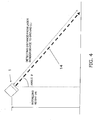
- the angle sensor 7 is a device which determines an angle ⁇ defined between the direction of the laser sensor device 1 (the direction of the laser emission light 14) and the vertical direction (see Fig. 4 ). Using the angle sensor, angle information of the laser emission light 14 can be automatically obtained when the laser sensor device 1 is installed. Any special operation is unnecessary, therefore, the operability is good.
- Fig. 2 illustrates a detail of the driving signal 17 inputted to the laser diode 8 and the driving signal 18 outputted from the avalanche photodiode 10.
- the driving signal 17 illustrated in Fig. 2 is inputted to the laser diode 8, and the laser diode 8 emits the laser emission light 14.
- the avalanche photodiode 10 receives the laser reflection light 15 to output the detecting signal 18.
- a time difference ⁇ between center positions of both the signals 17 and 18 is a time difference of both the signals 17 and 18 (light reciprocating time).
- the interval between the signals 17 and 18 is 34.7 ⁇ s, and the pulse width of each of the signals is 34 ns.
- Fig. 3 is a diagram of assistance in describing the monitoring area of the laser sensor device 1.
- scanning with the laser emission light 14 is performed by the scan mechanism portion 6 in a predetermined angle range.
- scanning with the laser emission light 14 is performed in the range of 180 degrees of an arc having a radius of 30 m.
- the scan distance of 30 m means that a spot of the laser emission light 14 is positioned at the height from the ground on the point of 30 m horizontally from the laser sensor device 1. Therefore, the guarding area of the laser sensor device 1 is an annular area inwardly a distance of about several meters from the point of 30 m (guarding distance) horizontally from the laser sensor device 1.
- an intruder Q who intrudes into the guarding area is illuminated with the laser emission light 14, and then reflects the laser reflection light 15.
- the direction of the laser emission light 14 is changed 720 times with 180 degrees.
- the laser emission light 14 is moved with a pitch of 13 cm.
- Fig. 7 is a flowchart illustrating human body detection processing of the software processing detection algorithm 5.
- step S1 distance information by the angle scanned by the sensor is inputted to the CPU.
- the distance information of rotation 720 times by the angle of 0.25 degrees is inputted from the TOF circuit signal processing portion 4.
- step S2 the distance information by the angle is developed to plane information in the CPU.
- step S3 an identified human body shape in the plane information is compared with a human body shape pattern map.
- the human body shape pattern is previously stored in a hard disk or another memory device.
- step S4 human body shape determination is performed. If it is determined that the identified human body shape is not the human body shape, the processing is ended and the routine returns to start. If it is determined that the identified human body shape is the human body shape, the routine is moved to step S5.
- step S5 the moving line tracking of the human body shape is performed.
- the identified human body shape in the continuously changed plane information is compared with the human body shape pattern map.
- step S6 the moving distance of the moving line is measured.
- the moving line tracking is continuously performed to measure its moving distance. For example, assume that the object to be detected intrudes into the guarding area to move to the laser sensor device 1. The object to be detected is scanned with the laser emission light 14 from its lower portion to its upper portion, and finally, its topmost portion is scanned. The next moment the scanning of the object to be detected is stopped, and the laser reflection light 15 from the object to be detected is not generated. Immediately before the scanning of the object to be detected is stopped, the topmost portion of the object to be detected is illuminated with the laser emission light 14.
- Fig. 4 is a schematic diagram of assistance in describing an operation of identifyings an installing height (H) from the ground by the laser sensor device 1.
- the object to be detected does not exist in this case, and the laser emission light 14 is applied to the ground.
- the distance information obtaining portion of the software processing detection algorithm 5 obtains the time difference ⁇ between both the signals 17 and 18 inputted from the TOF circuit signal processing portion 4 to compute a detecting distance L from the laser sensor device 1 to the ground based on the time difference.
- the software processing detection algorithm 5 can obtain the angle ⁇ formed between the emitting direction of the laser emission light 14 and the vertical direction by the angle sensor 7.
- Fig. 5 is a schematic diagram of assistance in describing an operation of identifying the height position of a head of the person to be detected P by the laser sensor device 1.
- the person to be detected Q intrudes toward the laser sensor device 1 at a distance (Y) from the position where the spot of the laser emission light 14 is positioned on the ground.
- the distance information obtaining portion of the software processing detection algorithm 5 obtains the time difference ⁇ between both the signals 17 and 18 inputted from the TOF circuit signal processing portion 4 to compute a detecting distance (m) from the laser sensor device 1 to the head of the intruder P based on the time difference.
- Fig. 6 is a schematic diagram of assistance in describing an operation of the laser sensor device 1 which identifies the height position of the head of a small animal to be detected A.
- the small animal to be detected A intrudes toward the laser sensor device 1 at a distance (M) from the position where the spot of the laser emission light 14 is positioned on the ground.
- the distance information obtaining portion of the software processing detection algorithm 5 obtains the time difference ⁇ between both the signals 17 and 18 inputted from the TOF circuit signal processing portion 4 to compute a detecting distance (n) from the laser sensor device 1 to the head of the small animal to be detected A based on the time difference.
- step S7 the moving distance data (at least any one of the detecting distance immediately before the tracking of the object to be detected is stopped, the height of the object to be detected, and the intruding distance) is stored in the memory device such as the hard disk.
- step S8 it is determined whether the moving distance data reaches a predetermined value or not. If the moving distance data is less than the predetermined value, the routine returns to start. If the moving distance data is not less than the predetermined value, the routine is moved to step S9.
- step S9 it is determined whether human body detection output is performed or not. If it is determined that the human body detection output is not performed, the routine returns to start. If it is determined that the human body detection output is performed, the routine is moved to step S10.
- step S10 output processing such as relay output is performed.
- the human body detection information is transmitted to the alarm device.
- the laser sensor device 1 is a device which detects the target by emitting and receiving the laser beam and has the laser emitting and receiving portion (2, 3), the distance information obtaining portion, the tracking stop determining portion, and the target determining portion.
- the laser emitting and receiving portion (2, 3) can emit the laser emission light 14 diagonally downward from the installing position.
- the distance information obtaining portion can obtain distance information from the laser emitting and receiving portion (2, 3) to the object to be detected.
- the tracking stop determining portion when the object to be detected approaches the laser emitting and receiving portion (2, 3), can determine whether the tracking of the object to be detected is stopped or not.
- the target determining portion when the tracking of the object to be detected is stopped, can determine whether the object to be detected is the target or the non-target based on distance information immediately before the tracking of the object to be detected is stopped.
- the laser emission light 14 is emitted diagonally downward from the laser emitting and receiving portion (2, 3) so that a wide detecting range can be maintained. If the distance information immediately before the tracking of the object to be detected is stopped shows the predetermined length or above, it is determined that the object to be detected is the target. If the distance information immediately before the tracking of the object to be detected is stopped shows less than the predetermined length, it is determined that the object to be detected is the non-target. Therefore, misdetection can be reduced while maintaining a wide detecting range.
- the target detecting method which detects the target by emitting the laser beam diagonally downward from the installing position of the laser emitting and receiving portion, includes the steps of: obtaining distance information from the laser emitting and receiving portion (2, 3) to the object to be detected; determining, when the object to be detected approaches the laser emitting and receiving portion, whether the tracking of the object to be detected is stopped or not (step S6 of Fig. 7 ); and determining, when the tracking of the object to be detected is stopped, whether the object to be detected is the target or the non-target based on distance information immediately before the tracking of the object to be detected is stopped (steps S6 and S7 of Fig. 7 ).
- the laser beam is emitted diagonally downward from the laser emitting and receiving portion (2, 3) so that a wide detecting range can be maintained. If the distance information immediately before the tracking of the object to be detected is stopped shows the predetermined length or above, it is determined that the object to be detected is the target. If the distance information immediately before the tracking of the object to be detected is stopped shows less than the predetermined length, it is determined that the object to be detected is the non-target. Therefore, the misdetection can be reduced while maintaining a wide detecting range.
- the angle sensor is used as means for obtaining angle information.
- the following angle information obtaining means can be used.
- an inputting portion such as a switch, which is provided in the laser sensor device and can input angle information or an inputting device (a keyboard or a mouse) of the computer which is connected to the laser sensor device via a network and can set the angle information to the laser sensor device.
- a human inputs the angle information special sensors are unnecessary and a cost is lowered.
- a computing portion which computes an angle based on installing height information of the laser sensor device and distance information from the laser sensor device to the ground can be used.
- the angle can be computed based on other information, the special sensors are unnecessary and the cost is lowered.
- the laser sensor device is used alone.
- the following combinations may also be used.
- detection is performed in the two-dimensional area by scanning with the laser beam.
- the following variations of the detecting position can also be provided.
- the moving line tracking is performed.
- the moving line tracking is not necessarily performed.
- the angle ⁇ of the direction of the laser emission light from the light emitting portion is secured in a predetermined range (for example, 10 to 80 degrees).
- the angle may have a small value close to 0 degrees. That is, the laser emission light performs illumination in an almost vertical direction (directly below).
- the detecting area becomes very small and the moving line tracking cannot be performed.
- detection and tracking stop are continuously performed. The height of the object to be detected can be detected from the detecting distance from the light emitting and receiving portion to the object to be detected immediately before the tracking stop. Therefore, the misdetection of the small animal is hard to occur.
- the laser emission light may be directed in an almost vertical direction as a result of scanning with the laser emission light up and down or right and left by the scan mechanism, or as a result of the laser emitting and receiving portion illuminating only at one point almost directly therebelow.
- Scanning may be performed such that the angle of the direction of the laser emission light from the laser emitting and receiving portion is directed in a vertical direction (directly below) other than diagonally downward.
- the direction of the laser emission light may also be fixed in a vertical direction.
- the target detecting device, the target detecting method, and the target detecting program according to the present invention are applicable to the guarding system.
Abstract
Description
- This application claims priority under 35 U.S.C. § 119 to Japanese Patent Application No.
2007-279651 filed on October 26, 2007 2007-279651 - The present invention relates to a target detecting device, a target detecting method, and a target detecting program, which detect a target. More specifically, the present invention relates to a target detecting device, a target detecting method, and a target detecting program, which detect a target by emitting and receiving a laser beam.
- A burglarproof system typically has a detecting device which detects a human who intrudes into a predetermined guarding area (hereinafter, referred to as an "intruder"), and an alarm generating device which generates an alarm based on a detected result. The detecting device is an infrared sensor or a laser sensor, which detects the intruder using a light beam. The alarm device permits lighting or flashing of an illuminating lamp and sounding of an alarm buzzer or a siren. The alarm device transmits an alarm signal to a facility to be guarded or a remote place. The burglarproof system further has an image displaying device which images the guarding area to display its image.
- To increase the detecting accuracy of a target, the laser sensor using a laser beam has been received attention as the detecting device. The laser sensor has a laser pulse generator (for example, including a laser diode), and a photodetector (for example, including an avalanche photodiode). The laser pulse generator generates a laser pulse wave. The photodetector detects a reflection light reflected from the target. Flight time, that is, reflection time is computed to measure a distance from the laser sensor to the target. A scan mechanism portion may further be provided to rotate a laser optical axis, and in this case, two-dimensional distance information can be obtained. Therefore, a wide monitoring area can be set (see Patent No. 3011121).
- The detecting device used for the burglarproof system need to be set so as to reliably detect a human and not to detect a small animal such as a dog or a cat. The detecting device often detects the small animal as the human to output a human body detecting signal, resulting in lowering of the reliability of the burglarproof system. To prevent misdetection, it is considered that the difference in height between the human and the small animal is used to install the laser sensor horizontally at about the height of a waist of an adult. In this case, the human is detected and the small animal is not detected. When the laser sensor is installed horizontally in a low position and an obstruction of about the height of the human exists between the laser sensor and the guarding area, it is difficult to avoid occurrence of a plurality of undetectable areas in the guarding area.
- An object of the present invention is to reduce the misdetection while maintaining a wide detecting range in a target detecting technique using a laser sensor.
- In a first aspect of the present invention, a target detecting device is a device for detecting a target by emitting and receiving a laser beam and has a laser emitting and receiving portion, a distance information obtaining portion, a tracking stop determining portion, and a target determining portion. The laser emitting and receiving portion can emit the laser beam diagonally downward from an installing position. The distance information obtaining portion can obtain distance information from the laser emitting and receiving portion to an object to be detected. The tracking stop determining portion, when the object to be detected approaches the laser emitting and receiving portion, can determine whether the tracking of the object to be detected is stopped or not. The target determining portion, when the tracking of the object to be detected is stopped, can determine whether the object to be detected is the target or a non-target based on distance information immediately before the tracking of the object to be detected is stopped.
- In the target detecting device, the laser beam is emitted diagonally downward from the laser emitting and receiving portion so that a wide detecting range can be maintained. When the tracking of the object to be detected is stopped, it can be determined whether the object to be detected is the target or the non-target based on the distance information immediately before the tracking of the object to be detected is stopped. Therefore, the misdetection can be reduced while maintaining a wide detecting range.
- In a second aspect of the present invention, the target detecting device according to the first aspect of the present invention, wherein the target determining portion, if the distance information immediately before the tracking of the object to be detected is stopped shows a predetermined length or above, determines that the object to be detected is the target, and if the distance information immediately before the tracking of the object to be detected is stopped shows less than the predetermined length, determines that the object to be detected is the non-target.
- In the target detecting device, it is determined that the object to be detected of the predetermined height or above is the target and that the object to be detected of less than the predetermined height is the non-target.
- In a third aspect of the present invention, the target detecting device according to the first or second aspect of the present invention, further includes a scan mechanism portion. The scan mechanism can change the direction of the laser beam emitted from the laser emitting and receiving portion.
- In the target detecting device, the direction of the laser beam emitted from the laser emitting and receiving portion can be changed by the scan mechanism portion. Therefore, the angle of the laser emission light, for example, is changed to detect the target in a two-dimensional area.
- In a fourth aspect of the present invention, a target detecting method for detecting a target by emitting a laser beam diagonally downward from an installing position of a laser emitting and receiving portion, includes the following steps.
The step of obtaining distance information from the laser emitting and receiving portion to an object to be detected.
The step of determining, when the object to be detected approaches the laser emitting and receiving portion, whether the tracking of the object to be detected is stopped or not.
The step of determining, when the tracking of the object to be detected is stopped, whether the object to be detected is the target or a non-target based on distance information immediately before the tracking of the object to be detected is stopped. - In the target detecting method, the laser beam is emitted diagonally downward from the laser emitting and receiving portion so that a wide detecting range can be maintained. When the tracking of the object to be detected is stopped, it can be determined whether the object to be detected is the target or the non-target based on the distance information immediately before the tracking of the object to be detected is stopped. Therefore, the misdetection can be reduced while maintaining a wide detecting range.
- In a fifth aspect of the present invention, the target detecting method according to the fourth aspect of the present invention, wherein the target determining step, if the distance information immediately before the tracking of the object to be detected is stopped shows a predetermined length or above, determines that the object to be detected is the target, and if the distance information immediately before the tracking of the object to be detected is stopped shows less than the predetermined length, determines that the object to be detected is the non-target.
- In the target detecting method, it is determined that the object to be detected of the predetermined height or above is the target and that the object to be detected of less than the predetermined height is the non-target.
- In a sixth aspect of the present invention, the target detecting method according to the fourth aspect of the present invention, wherein the target determining step, when the laser emitting and receiving portion emits the laser beam in an almost vertical direction, determines whether the object to be detected is the target or the non-target using the distance information immediately before the tracking of the object to be detected is stopped, as height information of the object to be detected.
- In the target detecting method, when the laser emitting and receiving portion emits the laser beam in the almost vertical direction, it is determined that the object to be detected of the predetermined height or above is the target and that the object to be detected of less than the predetermined height is the non-target.
- In a seventh aspect of the present invention, a target detecting program is a program that allows a computer to execute the target detecting method according to any one of the fourth to sixth aspect of the present invention.
- In the target detecting program, the misdetection can be reduced while maintaining a wide detecting range.
- In the target detecting device, the target detecting method, and the target detecting program according to the present invention, the misdetection can be reduced while maintaining a wide detecting range.
- These and other features, aspects and advantages of the present invention will become apparent to those skilled in the art from the following detailed description, which, taken in conjunction with the annexed drawings, discloses example embodiment of the present invention.
-
-
Fig. 1 is a block diagram illustrating a schematic configuration of a laser sensor device according to an embodiment of the present invention; -
Fig. 2 is a diagram illustrating a detail of a driving signal inputted to a laser diode and a detecting signal outputted from an avalanche photodiode; -
Fig. 3 is a diagram of assistance in describing a scan area of the laser sensor device; -
Fig. 4 is a schematic diagram of assistance in describing an operation of identifyings a height position from ground by the laser sensor device; -
Fig. 5 is a schematic diagram of assistance in describing an operation of identifying the height position of a head of a human by the laser sensor device; -
Fig. 6 is a schematic diagram of assistance in describing an operation of identifying the height position of a head of a dog by the laser sensor device; and -
Fig. 7 is a flowchart illustrating human body detection processing of a software processing detection algorithm. - Selected embodiments of the present invention will now be explained with reference to the drawings. It will be apparent to those skilled in the art from this disclosure that the following descriptions of the embodiments of the present invention are provided for illustration only and not for the purpose of limiting the invention as defined by the appended claims and their equivalents.
- In the following description, terms "guarding area", "detecting area", and "monitoring area" refer to a position in proximity to illumination of a laser emission light beam, and for example, include an area in which a human who is passing therethrough is illuminated with a laser beam. The term "target" is referred to as an object to be detected by a laser sensor and, in this embodiment, a human. The term "non-target" is referred to as an object which is unpreferable to be detected as the target and, in this embodiment, a small animal. The term "object to be detected" is referred to as an object in which it has not yet been determined whether it is the target or the non-target though its existence is detected.
-
Fig. 1 is a block diagram illustrating a schematic configuration of alaser sensor device 1 according to an embodiment of the present invention. Thelaser sensor device 1 is a device which emits a laser beam and then receives reflection light from a target to detect the target. Thelaser sensor device 1 is mainly used for burglar prevention in an area or a space having a predetermined range, such as a periphery of an entrance of a building, an open space, and an outside of a fence. Specifically, thelaser sensor device 1 is used for detecting an existence of an intruder in the guarding area. - The
laser sensor device 1 is combined with an alarm device and an image displaying device to configure a burglarproof system. The alarm device permits lighting or flashing of an illuminating lamp and sounding of an alarm buzzer or a siren. In some cases, the alarm device transmits an alarm signal to a facility to be guarded or a remote place. The image displaying device has a camera or a displaying device, and images and displays the image of the guarding area. - The
laser sensor device 1 mainly has alaser emitting portion 2 which is a laser pulse generator, alaser receiving portion 3 which is a photodetector, a TOF circuitsignal processing portion 4, a softwareprocessing detection algorithm 5, ascan mechanism portion 6, and anangle sensor 7. Thelaser sensor device 1 is, for example, installed in an upper position of a building and is used to have, as the monitoring area, an area diagonally downward therefrom. Thelaser sensor device 1 is preferably installed in the position at least above an average height of an adult. - The
laser emitting portion 2 mainly has alaser diode 8 and a light transmitting lens 9. Thelaser diode 8 emits laser emission light (laser pulse wave) 14. The laser emission light 14 passes through the light transmitting lens 9 so as to be directed to the detecting area by the scan mechanism portion 6 (described later). - The
laser receiving portion 3 mainly has anavalanche photodiode 10 and alight receiving lens 11. For example, laser reflection light 15 from a person to be detected P passes through thelight receiving lens 11 so as to be incident onto theavalanche photodiode 10. - The TOF (Time of Flight) circuit
signal processing portion 4 transmits a drivingsignal 17 to thelaser diode 8, receives a detectingsignal 18 from theavalanche photodiode 10, and performs signal processing based on thedetection signal 18. The TOF is a distance measuring technique which measures time during which a light pulse is moved to and returns from the surface of the target and then calculates the distance based on the measured time and a light speed. - The software
processing detection algorithm 5 is an algorithm which performs information processing by a computer and is realized by hardware (a CPU and memory) and software (a program). The softwareprocessing detection algorithm 5 has a distance information detecting portion, a tracking stop determining portion and a receiving portion. The distance information detecting portion can obtain distance information from the laser emitting and receiving portion (2, 3) to the object to be detected. The tracking stop determining portion can, when the object to be detected approaches the laser emitting and receiving portion, determine whether the tracking of the object to be detected is stopped or not. The target determining portion can, when the tracking of the object to be detected is stopped, determine whether the object to be detected is the target or the non-target based on distance information immediately before the tracking of the object to be detected is stopped. The operation of the softwareprocessing detection algorithm 5 will be described later. - The
scan mechanism portion 6 mainly has amirror 19 and a drivingportion 20. Themirror 19 reflects the laser emission light 14 from thelaser emitting portion 2. The drivingportion 20 rotates themirror 19 to change the direction of thelaser emission light 14. Thescan mechanism portion 6 can change the direction of the laser emission light 14 from thelaser emitting portion 2 right and left to detect the target in a two-dimensional area. - The
angle sensor 7 is a device which determines an angle θ defined between the direction of the laser sensor device 1 (the direction of the laser emission light 14) and the vertical direction (seeFig. 4 ). Using the angle sensor, angle information of thelaser emission light 14 can be automatically obtained when thelaser sensor device 1 is installed. Any special operation is unnecessary, therefore, the operability is good. -
Fig. 2 illustrates a detail of the drivingsignal 17 inputted to thelaser diode 8 and the drivingsignal 18 outputted from theavalanche photodiode 10. The drivingsignal 17 illustrated inFig. 2 is inputted to thelaser diode 8, and thelaser diode 8 emits thelaser emission light 14. Theavalanche photodiode 10 receives the laser reflection light 15 to output the detectingsignal 18. As is apparent fromFig. 2 , a time difference τ between center positions of both thesignals signals 17 and 18 (light reciprocating time). The interval between thesignals -
Fig. 3 is a diagram of assistance in describing the monitoring area of thelaser sensor device 1. As described above, in thelaser sensor device 1, scanning with thelaser emission light 14 is performed by thescan mechanism portion 6 in a predetermined angle range. InFig. 3 , scanning with thelaser emission light 14 is performed in the range of 180 degrees of an arc having a radius of 30 m. The scan distance of 30 m means that a spot of thelaser emission light 14 is positioned at the height from the ground on the point of 30 m horizontally from thelaser sensor device 1. Therefore, the guarding area of thelaser sensor device 1 is an annular area inwardly a distance of about several meters from the point of 30 m (guarding distance) horizontally from thelaser sensor device 1. As is apparent fromFig. 3 , an intruder Q who intrudes into the guarding area is illuminated with thelaser emission light 14, and then reflects thelaser reflection light 15. As an example, when thelaser emission light 14 is rotated by 0.25 degrees, the direction of thelaser emission light 14 is changed 720 times with 180 degrees. In the position of the radius of 30 m (guarding distance position), thelaser emission light 14 is moved with a pitch of 13 cm. -
Fig. 7 is a flowchart illustrating human body detection processing of the softwareprocessing detection algorithm 5. - In step S1, distance information by the angle scanned by the sensor is inputted to the CPU. The distance information of rotation 720 times by the angle of 0.25 degrees is inputted from the TOF circuit
signal processing portion 4. - In step S2, the distance information by the angle is developed to plane information in the CPU.
- In step S3, an identified human body shape in the plane information is compared with a human body shape pattern map. The human body shape pattern is previously stored in a hard disk or another memory device.
- In step S4, human body shape determination is performed. If it is determined that the identified human body shape is not the human body shape, the processing is ended and the routine returns to start. If it is determined that the identified human body shape is the human body shape, the routine is moved to step S5.
- In step S5, the moving line tracking of the human body shape is performed. The identified human body shape in the continuously changed plane information is compared with the human body shape pattern map.
- In step S6, the moving distance of the moving line is measured. The moving line tracking is continuously performed to measure its moving distance. For example, assume that the object to be detected intrudes into the guarding area to move to the
laser sensor device 1. The object to be detected is scanned with the laser emission light 14 from its lower portion to its upper portion, and finally, its topmost portion is scanned. The next moment the scanning of the object to be detected is stopped, and the laser reflection light 15 from the object to be detected is not generated. Immediately before the scanning of the object to be detected is stopped, the topmost portion of the object to be detected is illuminated with thelaser emission light 14. That is, when the object to be detected intrudes into the guarding area to approach thelaser sensor device 1 and the moving line tracking is then stopped, detecting distance information detected immediately before the tracking is stopped is obtained. Both the height of the object to be detected and an intruding distance can be computed based on the detecting distance information and the angle information obtained by theangle sensor 7. The above contents will be described below in detail. -
Fig. 4 is a schematic diagram of assistance in describing an operation of identifyings an installing height (H) from the ground by thelaser sensor device 1. The object to be detected does not exist in this case, and thelaser emission light 14 is applied to the ground. The distance information obtaining portion of the softwareprocessing detection algorithm 5 obtains the time difference τ between both thesignals signal processing portion 4 to compute a detecting distance L from thelaser sensor device 1 to the ground based on the time difference. The softwareprocessing detection algorithm 5 can obtain the angle θ formed between the emitting direction of thelaser emission light 14 and the vertical direction by theangle sensor 7. The softwareprocessing detection algorithm 5 can obtain the installing height (H) by an expression H = cosθ × L. -
Fig. 5 is a schematic diagram of assistance in describing an operation of identifying the height position of a head of the person to be detected P by thelaser sensor device 1. The person to be detected Q intrudes toward thelaser sensor device 1 at a distance (Y) from the position where the spot of thelaser emission light 14 is positioned on the ground. The distance information obtaining portion of the softwareprocessing detection algorithm 5 obtains the time difference τ between both thesignals signal processing portion 4 to compute a detecting distance (m) from thelaser sensor device 1 to the head of the intruder P based on the time difference. The softwareprocessing detection algorithm 5 can obtain a height X of the person to be detected P by the expression X = H - cosθ × 1. The softwareprocessing detection algorithm 5 can obtain the intruding distance (Y) by the expression Y = sinθ × (L-1). -
Fig. 6 is a schematic diagram of assistance in describing an operation of thelaser sensor device 1 which identifies the height position of the head of a small animal to be detected A. In this case, the small animal to be detected A intrudes toward thelaser sensor device 1 at a distance (M) from the position where the spot of thelaser emission light 14 is positioned on the ground. The distance information obtaining portion of the softwareprocessing detection algorithm 5 obtains the time difference τ between both thesignals signal processing portion 4 to compute a detecting distance (n) from thelaser sensor device 1 to the head of the small animal to be detected A based on the time difference. The softwareprocessing detection algorithm 5 can obtain a height (Z) of the small animal to be detected A by the expression Z = H - cosθ × n. The softwareprocessing detection algorithm 5 can obtain the intruding distance (M) by the expression M = sinθ × (L - n). - In step S7, the moving distance data (at least any one of the detecting distance immediately before the tracking of the object to be detected is stopped, the height of the object to be detected, and the intruding distance) is stored in the memory device such as the hard disk.
- In step S8, it is determined whether the moving distance data reaches a predetermined value or not. If the moving distance data is less than the predetermined value, the routine returns to start. If the moving distance data is not less than the predetermined value, the routine is moved to step S9.
- In step S9, it is determined whether human body detection output is performed or not. If it is determined that the human body detection output is not performed, the routine returns to start. If it is determined that the human body detection output is performed, the routine is moved to step S10.
- In step S10, output processing such as relay output is performed. For example, the human body detection information is transmitted to the alarm device.
- 1) The
laser sensor device 1 according to the present invention is a device which detects the target by emitting and receiving the laser beam and has the laser emitting and receiving portion (2, 3), the distance information obtaining portion, the tracking stop determining portion, and the target determining portion. The laser emitting and receiving portion (2, 3) can emit thelaser emission light 14 diagonally downward from the installing position. The distance information obtaining portion can obtain distance information from the laser emitting and receiving portion (2, 3) to the object to be detected. The tracking stop determining portion, when the object to be detected approaches the laser emitting and receiving portion (2, 3), can determine whether the tracking of the object to be detected is stopped or not. The target determining portion, when the tracking of the object to be detected is stopped, can determine whether the object to be detected is the target or the non-target based on distance information immediately before the tracking of the object to be detected is stopped. - In the
laser sensor device 1, thelaser emission light 14 is emitted diagonally downward from the laser emitting and receiving portion (2, 3) so that a wide detecting range can be maintained. If the distance information immediately before the tracking of the object to be detected is stopped shows the predetermined length or above, it is determined that the object to be detected is the target. If the distance information immediately before the tracking of the object to be detected is stopped shows less than the predetermined length, it is determined that the object to be detected is the non-target. Therefore, misdetection can be reduced while maintaining a wide detecting range. - 2) The target detecting method according to the present invention which detects the target by emitting the laser beam diagonally downward from the installing position of the laser emitting and receiving portion, includes the steps of: obtaining distance information from the laser emitting and receiving portion (2, 3) to the object to be detected; determining, when the object to be detected approaches the laser emitting and receiving portion, whether the tracking of the object to be detected is stopped or not (step S6 of
Fig. 7 ); and determining, when the tracking of the object to be detected is stopped, whether the object to be detected is the target or the non-target based on distance information immediately before the tracking of the object to be detected is stopped (steps S6 and S7 ofFig. 7 ). - In the target detecting method, the laser beam is emitted diagonally downward from the laser emitting and receiving portion (2, 3) so that a wide detecting range can be maintained. If the distance information immediately before the tracking of the object to be detected is stopped shows the predetermined length or above, it is determined that the object to be detected is the target. If the distance information immediately before the tracking of the object to be detected is stopped shows less than the predetermined length, it is determined that the object to be detected is the non-target. Therefore, the misdetection can be reduced while maintaining a wide detecting range.
- The present invention is not limited to the above embodiment and various changes and modifications can be made without departing from the scope of the present invention.
- (1) In the above embodiment, the angle sensor is used as means for obtaining angle information. The following angle information obtaining means can be used.
1) There can be used an inputting portion, such as a switch, which is provided in the laser sensor device and can input angle information or an inputting device (a keyboard or a mouse) of the computer which is connected to the laser sensor device via a network and can set the angle information to the laser sensor device. In this laser sensor device, since a human inputs the angle information, special sensors are unnecessary and a cost is lowered. - 2) A computing portion which computes an angle based on installing height information of the laser sensor device and distance information from the laser sensor device to the ground can be used. In this laser sensor device, since the angle can be computed based on other information, the special sensors are unnecessary and the cost is lowered.
- (2) In the above embodiment, the laser sensor device is used alone. The following combinations may also be used.
- 1) A plurality of the laser sensor devices of the above embodiment can be combined.
- 2) The laser sensor device of the above embodiment and a laser sensor device which horizontally emits the laser emission light can be combined.
- (3) In the above embodiment, detection is performed in the two-dimensional area by scanning with the laser beam. The following variations of the detecting position can also be provided.
- 1) Detection can be performed only at one point without moving the laser emission light. It is sufficiently effective when the guarding area is small like a gate.
- 2) Detection on the plane can be performed by moving the laser emission light up and down as well as right and left.
- (4) In the above embodiment, when the moving line tracking of the object to be detected is stopped, at least any one of the distance information of the object to be detected immediately before the moving line tracking of the object to be detected is stopped, the height information of the object to be detected, and the intruding distance information is used to determine whether the object to be detected is the human or not. The following variations of the means for obtaining the height information and the intruding distance information are considered.
- 1) The height information and the intruding distance information are computed based on the distance information of the object to be detected immediately before the tracking is stopped.
- 2) A conversion table is prepared to take out the corresponding height information and intruding distance information from the conversion table based on the distance information of the object to be detected immediately before the tracking is stopped.
- (5) In the above embodiment, the moving line tracking is performed. The moving line tracking is not necessarily performed.
- (6) In the above embodiment, the angle θ of the direction of the laser emission light from the light emitting portion is secured in a predetermined range (for example, 10 to 80 degrees). The angle may have a small value close to 0 degrees. That is, the laser emission light performs illumination in an almost vertical direction (directly below). In this case, the detecting area becomes very small and the moving line tracking cannot be performed. When the object to be detected passes through the detecting area, detection and tracking stop are continuously performed. The height of the object to be detected can be detected from the detecting distance from the light emitting and receiving portion to the object to be detected immediately before the tracking stop. Therefore, the misdetection of the small animal is hard to occur.
- The laser emission light may be directed in an almost vertical direction as a result of scanning with the laser emission light up and down or right and left by the scan mechanism, or as a result of the laser emitting and receiving portion illuminating only at one point almost directly therebelow.
- (7) Scanning may be performed such that the angle of the direction of the laser emission light from the laser emitting and receiving portion is directed in a vertical direction (directly below) other than diagonally downward. The direction of the laser emission light may also be fixed in a vertical direction.
- The target detecting device, the target detecting method, and the target detecting program according to the present invention are applicable to the guarding system.
- As used herein, the following directional terms "forward, rearward, above, downward, vertical, horizontal, below and transverse" as well as any other similar directional terms refer to those directions of a device equipped with the present invention. Accordingly, these terms, as utilized to describe the present invention should be interpreted relative to a device equipped with the present invention.
- While only selected embodiments have been chosen to illustrate the present invention, it will be apparent to those skilled in the art from this disclosure that various changes and modifications can be made herein without departing from the scope of the invention as defined in the appended claims. Furthermore, the foregoing descriptions of the embodiments according to the present invention are provided for illustration only, and not for the purpose of limiting the invention as defined by the appended claims and their equivalents. Thus, the scope of the invention is not limited to the disclosed embodiments.
Claims (7)
- A target detecting device for detecting a target by emitting and receiving a laser beam, the device comprising:a laser emitting and receiving portion configured to emit the laser beam diagonally downward from an installing position;a distance information obtaining portion configured to obtain distance information from the laser emitting and receiving portion to an object to be detected;a tracking stop determining portion configured, when the object to be detected approaches the laser emitting and receiving portion, to determine whether tracking of the object to be detected is stopped or not; anda target determining portion, configured to determines, when the tracking of the object to be detected is stopped, whether the object to be detected is the target or a non-target based on distance information immediately before the tracking of the object to be detected is stopped.
- The target detecting device according to claim 1, wherein the target determining portion, if the distance information immediately before the tracking of the object to be detected is stopped shows a predetermined length or above, determines that the object to be detected is the target, and if the distance information immediately before the tracking of the object to be detected is stopped shows less than the predetermined length, determines that the object to be detected is the non-target.
- The target detecting device according to claim 1 or 2, further comprising a scan mechanism portion configured to changes the direction of the laser beam emitted from the laser emitting and receiving portion.
- A target detecting method for detecting a target by emitting a laser beam diagonally downward from an installing position of a laser emitting and receiving portion, the method comprising:obtaining distance information from the laser emitting and receiving portion to an object to be detected;determining, when the object to be detected approaches the laser emitting and receiving portion, whether tracking of the object to be detected is stopped or not; anddetermining, when the tracking of the object to be detected is stopped, whether the object to be detected is the target or a non-target based on distance information immediately before the tracking of the object to be detected is stopped.
- The target detecting method according to claim 4, wherein the target determining step, if the distance information immediately before the tracking of the object to be detected is stopped shows a predetermined length or above, determines that the object to be detected is the target, and if the distance information immediately before the tracking of the object to be detected is stopped shows less than the predetermined length, determines that the object to be detected is the non-target.
- The target detecting method according to claim 4, wherein the target determining step, when the laser emitting and receiving portion emits the laser beam in an almost vertical direction, determines whether the object to be detected is the target or the non-target using the distance information immediately before the tracking of the object to be detected is stopped, as height information of the object to be detected.
- A target detecting program that allows a computer to execute the target detecting method according to any one of claims 4 to 6.
Applications Claiming Priority (1)
| Application Number | Priority Date | Filing Date | Title |
|---|---|---|---|
| JP2007279651A JP5076070B2 (en) | 2007-10-26 | 2007-10-26 | Object detection device, object detection method, and object detection program |
Publications (2)
| Publication Number | Publication Date |
|---|---|
| EP2053424A1 true EP2053424A1 (en) | 2009-04-29 |
| EP2053424B1 EP2053424B1 (en) | 2012-06-20 |
Family
ID=40242617
Family Applications (1)
| Application Number | Title | Priority Date | Filing Date |
|---|---|---|---|
| EP08018380A Active EP2053424B1 (en) | 2007-10-26 | 2008-10-21 | Target detecting device, target detecting method, and target detecting program |
Country Status (3)
| Country | Link |
|---|---|
| US (1) | US8420998B2 (en) |
| EP (1) | EP2053424B1 (en) |
| JP (1) | JP5076070B2 (en) |
Cited By (7)
| Publication number | Priority date | Publication date | Assignee | Title |
|---|---|---|---|---|
| CN102927909A (en) * | 2012-11-05 | 2013-02-13 | 河南理工大学 | Laser beam fast automatic positioning tracking measurement method and device |
| EP2709080A1 (en) * | 2012-09-13 | 2014-03-19 | MBDA UK Limited | Room occupancy sensing apparatus and method |
| WO2014041350A1 (en) * | 2012-09-13 | 2014-03-20 | Mbda Uk Limited | Room occupancy sensing apparatus and method |
| EP2741263A1 (en) * | 2011-11-09 | 2014-06-11 | Optex Co., Ltd. | Laser scan sensor |
| GB2570910A (en) * | 2018-02-09 | 2019-08-14 | Hi Tec Security Systems Ltd | Method and system for targeting and tracking an intruder using a laser detection and ranging device |
| WO2021206981A1 (en) * | 2020-04-06 | 2021-10-14 | Universal City Studios Llc | Sensing system for an interactive system |
| CN113534173A (en) * | 2020-04-14 | 2021-10-22 | 上海禾赛科技有限公司 | Laser radar, detection method using same, and translational scanning method |
Families Citing this family (17)
| Publication number | Priority date | Publication date | Assignee | Title |
|---|---|---|---|---|
| JP5251735B2 (en) * | 2008-11-28 | 2013-07-31 | 株式会社デンソーウェーブ | Laser radar equipment |
| EP2267674A1 (en) * | 2009-06-11 | 2010-12-29 | Koninklijke Philips Electronics N.V. | Subject detection |
| DE102009046158A1 (en) * | 2009-10-29 | 2011-05-05 | Robert Bosch Gmbh | Method for detecting objects with low height |
| JP5728815B2 (en) * | 2010-03-18 | 2015-06-03 | 株式会社豊田中央研究所 | Object detection device |
| JP5497514B2 (en) * | 2010-03-31 | 2014-05-21 | セコム株式会社 | Object detection sensor and security system |
| JP5375785B2 (en) * | 2010-09-17 | 2013-12-25 | 株式会社デンソーウェーブ | Intrusion detection device |
| DK2506034T3 (en) | 2011-04-01 | 2013-09-02 | Cedes Ag | Sensor device, safety device, door and movement control method |
| JP5694834B2 (en) * | 2011-04-12 | 2015-04-01 | グローリー株式会社 | Object recognition method and object recognition apparatus |
| JP5163971B1 (en) * | 2011-09-12 | 2013-03-13 | オプテックス株式会社 | Laser scan sensor |
| JP6158669B2 (en) * | 2013-10-01 | 2017-07-05 | フマキラー株式会社 | Animal repellent device |
| US9799044B2 (en) * | 2013-12-26 | 2017-10-24 | Panasonic Intellectual Property Corporation Of America | Control method, and control system |
| US9739609B1 (en) * | 2014-03-25 | 2017-08-22 | Amazon Technologies, Inc. | Time-of-flight sensor with configurable phase delay |
| DE102014110203B3 (en) * | 2014-07-21 | 2015-08-06 | Sick Ag | Distance measuring sensor for the detection and distance determination of objects |
| CN106315324B (en) | 2015-06-16 | 2020-04-14 | 奥的斯电梯公司 | Elevator system capable of monitoring use of children and control method thereof |
| US11073602B2 (en) * | 2016-06-15 | 2021-07-27 | Stmicroelectronics, Inc. | Time of flight user identification based control systems and methods |
| JP2021173726A (en) * | 2020-04-30 | 2021-11-01 | 株式会社デンソーウェーブ | Laser distance measuring device and object detection system |
| CN116704685B (en) * | 2023-07-31 | 2023-11-14 | 东方信腾档案管理有限公司 | Infrared wireless intrusion detector and detection method thereof |
Citations (7)
| Publication number | Priority date | Publication date | Assignee | Title |
|---|---|---|---|---|
| JPH07160956A (en) * | 1993-12-13 | 1995-06-23 | Nec Corp | Intrusion supervisory equipment |
| US6304321B1 (en) * | 1992-11-23 | 2001-10-16 | Schwartz Electro-Optics, Inc. | Vehicle classification and axle counting sensor system and method |
| US20030112142A1 (en) | 2001-12-19 | 2003-06-19 | Hitachi, Ltd. | Security system |
| US6583403B1 (en) * | 1999-10-26 | 2003-06-24 | Honda Giken Kogyo Kabushiki Kaisha | Object detecting device, and travel safety system for vehicle |
| US20060267764A1 (en) * | 2005-05-30 | 2006-11-30 | Hitachi, Ltd. | Object detection sensor |
| WO2007029610A1 (en) * | 2005-09-05 | 2007-03-15 | Optex Co., Ltd. | Intrusion sensor |
| JP2007279651A (en) | 2006-03-17 | 2007-10-25 | Dainippon Printing Co Ltd | Incident-angle-dependent diffraction grating |
Family Cites Families (12)
| Publication number | Priority date | Publication date | Assignee | Title |
|---|---|---|---|---|
| GB1451192A (en) * | 1972-08-18 | 1976-09-29 | Solartron Electronic Group | Weapon training systems |
| JPS62296601A (en) | 1986-06-17 | 1987-12-23 | Nippon Dengiyou Kosaku Kk | Low-pass filter |
| DE4130619A1 (en) * | 1991-09-14 | 1993-03-25 | Deutsche Aerospace | OBJECT PROTECTION |
| JP3011121B2 (en) | 1997-02-28 | 2000-02-21 | 日本電気株式会社 | Security system |
| US5910767A (en) * | 1997-07-11 | 1999-06-08 | Laser Guard | Intruder detector system |
| US6014220A (en) * | 1997-11-10 | 2000-01-11 | Kabushiki Kaisha Topcon | Automatic control system for construction machinery |
| JPH11257931A (en) * | 1998-03-13 | 1999-09-24 | Matsushita Electric Ind Co Ltd | Object recognizing device |
| JP2000036083A (en) * | 1998-07-16 | 2000-02-02 | Hyper Electronics:Kk | Entering object monitoring device |
| JP2002277212A (en) * | 2001-03-16 | 2002-09-25 | Fuji Electric Co Ltd | Intruder detecting device |
| JP2003090877A (en) * | 2001-07-12 | 2003-03-28 | Murata Mfg Co Ltd | Radar device |
| JP4238042B2 (en) * | 2003-02-07 | 2009-03-11 | 住友大阪セメント株式会社 | Monitoring device and monitoring method |
| JP5187878B2 (en) * | 2007-01-31 | 2013-04-24 | 国立大学法人 東京大学 | Object measurement system |
-
2007
- 2007-10-26 JP JP2007279651A patent/JP5076070B2/en active Active
-
2008
- 2008-10-21 US US12/255,198 patent/US8420998B2/en active Active
- 2008-10-21 EP EP08018380A patent/EP2053424B1/en active Active
Patent Citations (7)
| Publication number | Priority date | Publication date | Assignee | Title |
|---|---|---|---|---|
| US6304321B1 (en) * | 1992-11-23 | 2001-10-16 | Schwartz Electro-Optics, Inc. | Vehicle classification and axle counting sensor system and method |
| JPH07160956A (en) * | 1993-12-13 | 1995-06-23 | Nec Corp | Intrusion supervisory equipment |
| US6583403B1 (en) * | 1999-10-26 | 2003-06-24 | Honda Giken Kogyo Kabushiki Kaisha | Object detecting device, and travel safety system for vehicle |
| US20030112142A1 (en) | 2001-12-19 | 2003-06-19 | Hitachi, Ltd. | Security system |
| US20060267764A1 (en) * | 2005-05-30 | 2006-11-30 | Hitachi, Ltd. | Object detection sensor |
| WO2007029610A1 (en) * | 2005-09-05 | 2007-03-15 | Optex Co., Ltd. | Intrusion sensor |
| JP2007279651A (en) | 2006-03-17 | 2007-10-25 | Dainippon Printing Co Ltd | Incident-angle-dependent diffraction grating |
Cited By (11)
| Publication number | Priority date | Publication date | Assignee | Title |
|---|---|---|---|---|
| EP2741263A1 (en) * | 2011-11-09 | 2014-06-11 | Optex Co., Ltd. | Laser scan sensor |
| EP2741263A4 (en) * | 2011-11-09 | 2015-01-07 | Optex Co Ltd | Laser scan sensor |
| US9182489B2 (en) | 2011-11-09 | 2015-11-10 | Optex Co., Ltd. | Laser scan sensor |
| EP2709080A1 (en) * | 2012-09-13 | 2014-03-19 | MBDA UK Limited | Room occupancy sensing apparatus and method |
| WO2014041350A1 (en) * | 2012-09-13 | 2014-03-20 | Mbda Uk Limited | Room occupancy sensing apparatus and method |
| US9575180B2 (en) | 2012-09-13 | 2017-02-21 | Mbda Uk Limited | Room occupancy sensing apparatus and method |
| CN102927909A (en) * | 2012-11-05 | 2013-02-13 | 河南理工大学 | Laser beam fast automatic positioning tracking measurement method and device |
| CN102927909B (en) * | 2012-11-05 | 2015-02-25 | 河南理工大学 | Laser beam fast automatic positioning tracking measurement method and device |
| GB2570910A (en) * | 2018-02-09 | 2019-08-14 | Hi Tec Security Systems Ltd | Method and system for targeting and tracking an intruder using a laser detection and ranging device |
| WO2021206981A1 (en) * | 2020-04-06 | 2021-10-14 | Universal City Studios Llc | Sensing system for an interactive system |
| CN113534173A (en) * | 2020-04-14 | 2021-10-22 | 上海禾赛科技有限公司 | Laser radar, detection method using same, and translational scanning method |
Also Published As
| Publication number | Publication date |
|---|---|
| JP2009110124A (en) | 2009-05-21 |
| US20090108184A1 (en) | 2009-04-30 |
| JP5076070B2 (en) | 2012-11-21 |
| US8420998B2 (en) | 2013-04-16 |
| EP2053424B1 (en) | 2012-06-20 |
Similar Documents
| Publication | Publication Date | Title |
|---|---|---|
| EP2053424B1 (en) | Target detecting device, target detecting method, and target detecting program | |
| US7940178B2 (en) | Laser area sensor | |
| US4967183A (en) | Method of intrusion detection over a wide area | |
| JP4691701B2 (en) | Number detection device and method | |
| EP2899705B1 (en) | Laser scan sensor | |
| JPH02504440A (en) | Intrusion detection method | |
| JP2008026997A (en) | Pedestrian recognition device and pedestrian recognition method | |
| JP2003214851A (en) | Method and apparatus for automatically searching for target mark, reception unit, and geodetic meter and system | |
| JP3011121B2 (en) | Security system | |
| EP1778531B1 (en) | A monitoring device | |
| EP2741263B1 (en) | Laser scan sensor | |
| JP5163971B1 (en) | Laser scan sensor | |
| EP3875989B1 (en) | Laser scanning sensor | |
| EP1730008A1 (en) | A monitoring device | |
| JP5995485B2 (en) | Lane detection device | |
| KR20180081007A (en) | Wide angle LiDAR and operation method thereof | |
| WO2023132057A1 (en) | Laser scanning sensor | |
| JP2021173726A (en) | Laser distance measuring device and object detection system |
Legal Events
| Date | Code | Title | Description |
|---|---|---|---|
| PUAI | Public reference made under article 153(3) epc to a published international application that has entered the european phase |
Free format text: ORIGINAL CODE: 0009012 |
|
| AK | Designated contracting states |
Kind code of ref document: A1 Designated state(s): AT BE BG CH CY CZ DE DK EE ES FI FR GB GR HR HU IE IS IT LI LT LU LV MC MT NL NO PL PT RO SE SI SK TR |
|
| AX | Request for extension of the european patent |
Extension state: AL BA MK RS |
|
| 17P | Request for examination filed |
Effective date: 20091015 |
|
| AKX | Designation fees paid |
Designated state(s): AT BE BG CH CY CZ DE DK EE ES FI FR GB GR HR HU IE IS IT LI LT LU LV MC MT NL NO PL PT RO SE SI SK TR |
|
| 17Q | First examination report despatched |
Effective date: 20100629 |
|
| REG | Reference to a national code |
Ref country code: DE Ref legal event code: R079 Ref document number: 602008016371 Country of ref document: DE Free format text: PREVIOUS MAIN CLASS: G01S0017020000 Ipc: G01S0017660000 |
|
| GRAP | Despatch of communication of intention to grant a patent |
Free format text: ORIGINAL CODE: EPIDOSNIGR1 |
|
| RIC1 | Information provided on ipc code assigned before grant |
Ipc: G08B 13/184 20060101ALI20111202BHEP Ipc: G08B 13/24 20060101ALI20111202BHEP Ipc: G01S 17/46 20060101ALI20111202BHEP Ipc: G01S 17/02 20060101ALI20111202BHEP Ipc: G01S 17/66 20060101AFI20111202BHEP Ipc: G01S 7/48 20060101ALI20111202BHEP |
|
| GRAS | Grant fee paid |
Free format text: ORIGINAL CODE: EPIDOSNIGR3 |
|
| GRAA | (expected) grant |
Free format text: ORIGINAL CODE: 0009210 |
|
| RIN1 | Information on inventor provided before grant (corrected) |
Inventor name: IWASAWA, MASASHI |
|
| RIN1 | Information on inventor provided before grant (corrected) |
Inventor name: IWASAWA, MASASHI |
|
| RAP1 | Party data changed (applicant data changed or rights of an application transferred) |
Owner name: OPTEX CO., LTD. |
|
| AK | Designated contracting states |
Kind code of ref document: B1 Designated state(s): AT BE BG CH CY CZ DE DK EE ES FI FR GB GR HR HU IE IS IT LI LT LU LV MC MT NL NO PL PT RO SE SI SK TR |
|
| REG | Reference to a national code |
Ref country code: GB Ref legal event code: FG4D |
|
| RIN2 | Information on inventor provided after grant (corrected) |
Inventor name: IWASAWA, MASASHI |
|
| REG | Reference to a national code |
Ref country code: CH Ref legal event code: EP |
|
| REG | Reference to a national code |
Ref country code: AT Ref legal event code: REF Ref document number: 563355 Country of ref document: AT Kind code of ref document: T Effective date: 20120715 |
|
| REG | Reference to a national code |
Ref country code: IE Ref legal event code: FG4D |
|
| REG | Reference to a national code |
Ref country code: DE Ref legal event code: R096 Ref document number: 602008016371 Country of ref document: DE Effective date: 20120816 |
|
| PG25 | Lapsed in a contracting state [announced via postgrant information from national office to epo] |
Ref country code: NO Free format text: LAPSE BECAUSE OF FAILURE TO SUBMIT A TRANSLATION OF THE DESCRIPTION OR TO PAY THE FEE WITHIN THE PRESCRIBED TIME-LIMIT Effective date: 20120920 Ref country code: FI Free format text: LAPSE BECAUSE OF FAILURE TO SUBMIT A TRANSLATION OF THE DESCRIPTION OR TO PAY THE FEE WITHIN THE PRESCRIBED TIME-LIMIT Effective date: 20120620 Ref country code: SE Free format text: LAPSE BECAUSE OF FAILURE TO SUBMIT A TRANSLATION OF THE DESCRIPTION OR TO PAY THE FEE WITHIN THE PRESCRIBED TIME-LIMIT Effective date: 20120620 Ref country code: LT Free format text: LAPSE BECAUSE OF FAILURE TO SUBMIT A TRANSLATION OF THE DESCRIPTION OR TO PAY THE FEE WITHIN THE PRESCRIBED TIME-LIMIT Effective date: 20120620 |
|
| REG | Reference to a national code |
Ref country code: NL Ref legal event code: VDEP Effective date: 20120620 |
|
| REG | Reference to a national code |
Ref country code: AT Ref legal event code: MK05 Ref document number: 563355 Country of ref document: AT Kind code of ref document: T Effective date: 20120620 |
|
| REG | Reference to a national code |
Ref country code: LT Ref legal event code: MG4D Effective date: 20120620 |
|
| PG25 | Lapsed in a contracting state [announced via postgrant information from national office to epo] |
Ref country code: GR Free format text: LAPSE BECAUSE OF FAILURE TO SUBMIT A TRANSLATION OF THE DESCRIPTION OR TO PAY THE FEE WITHIN THE PRESCRIBED TIME-LIMIT Effective date: 20120921 Ref country code: HR Free format text: LAPSE BECAUSE OF FAILURE TO SUBMIT A TRANSLATION OF THE DESCRIPTION OR TO PAY THE FEE WITHIN THE PRESCRIBED TIME-LIMIT Effective date: 20120620 Ref country code: SI Free format text: LAPSE BECAUSE OF FAILURE TO SUBMIT A TRANSLATION OF THE DESCRIPTION OR TO PAY THE FEE WITHIN THE PRESCRIBED TIME-LIMIT Effective date: 20120620 |
|
| PG25 | Lapsed in a contracting state [announced via postgrant information from national office to epo] |
Ref country code: CY Free format text: LAPSE BECAUSE OF FAILURE TO SUBMIT A TRANSLATION OF THE DESCRIPTION OR TO PAY THE FEE WITHIN THE PRESCRIBED TIME-LIMIT Effective date: 20120620 Ref country code: EE Free format text: LAPSE BECAUSE OF FAILURE TO SUBMIT A TRANSLATION OF THE DESCRIPTION OR TO PAY THE FEE WITHIN THE PRESCRIBED TIME-LIMIT Effective date: 20120620 Ref country code: AT Free format text: LAPSE BECAUSE OF FAILURE TO SUBMIT A TRANSLATION OF THE DESCRIPTION OR TO PAY THE FEE WITHIN THE PRESCRIBED TIME-LIMIT Effective date: 20120620 Ref country code: BE Free format text: LAPSE BECAUSE OF FAILURE TO SUBMIT A TRANSLATION OF THE DESCRIPTION OR TO PAY THE FEE WITHIN THE PRESCRIBED TIME-LIMIT Effective date: 20120620 Ref country code: RO Free format text: LAPSE BECAUSE OF FAILURE TO SUBMIT A TRANSLATION OF THE DESCRIPTION OR TO PAY THE FEE WITHIN THE PRESCRIBED TIME-LIMIT Effective date: 20120620 Ref country code: SK Free format text: LAPSE BECAUSE OF FAILURE TO SUBMIT A TRANSLATION OF THE DESCRIPTION OR TO PAY THE FEE WITHIN THE PRESCRIBED TIME-LIMIT Effective date: 20120620 Ref country code: CZ Free format text: LAPSE BECAUSE OF FAILURE TO SUBMIT A TRANSLATION OF THE DESCRIPTION OR TO PAY THE FEE WITHIN THE PRESCRIBED TIME-LIMIT Effective date: 20120620 Ref country code: IS Free format text: LAPSE BECAUSE OF FAILURE TO SUBMIT A TRANSLATION OF THE DESCRIPTION OR TO PAY THE FEE WITHIN THE PRESCRIBED TIME-LIMIT Effective date: 20121020 |
|
| PG25 | Lapsed in a contracting state [announced via postgrant information from national office to epo] |
Ref country code: PT Free format text: LAPSE BECAUSE OF FAILURE TO SUBMIT A TRANSLATION OF THE DESCRIPTION OR TO PAY THE FEE WITHIN THE PRESCRIBED TIME-LIMIT Effective date: 20121022 Ref country code: PL Free format text: LAPSE BECAUSE OF FAILURE TO SUBMIT A TRANSLATION OF THE DESCRIPTION OR TO PAY THE FEE WITHIN THE PRESCRIBED TIME-LIMIT Effective date: 20120620 |
|
| PG25 | Lapsed in a contracting state [announced via postgrant information from national office to epo] |
Ref country code: NL Free format text: LAPSE BECAUSE OF FAILURE TO SUBMIT A TRANSLATION OF THE DESCRIPTION OR TO PAY THE FEE WITHIN THE PRESCRIBED TIME-LIMIT Effective date: 20120620 |
|
| PLBE | No opposition filed within time limit |
Free format text: ORIGINAL CODE: 0009261 |
|
| STAA | Information on the status of an ep patent application or granted ep patent |
Free format text: STATUS: NO OPPOSITION FILED WITHIN TIME LIMIT |
|
| PG25 | Lapsed in a contracting state [announced via postgrant information from national office to epo] |
Ref country code: ES Free format text: LAPSE BECAUSE OF FAILURE TO SUBMIT A TRANSLATION OF THE DESCRIPTION OR TO PAY THE FEE WITHIN THE PRESCRIBED TIME-LIMIT Effective date: 20121001 Ref country code: DK Free format text: LAPSE BECAUSE OF FAILURE TO SUBMIT A TRANSLATION OF THE DESCRIPTION OR TO PAY THE FEE WITHIN THE PRESCRIBED TIME-LIMIT Effective date: 20120620 |
|
| 26N | No opposition filed |
Effective date: 20130321 |
|
| PG25 | Lapsed in a contracting state [announced via postgrant information from national office to epo] |
Ref country code: MC Free format text: LAPSE BECAUSE OF NON-PAYMENT OF DUE FEES Effective date: 20121031 |
|
| REG | Reference to a national code |
Ref country code: CH Ref legal event code: PL |
|
| REG | Reference to a national code |
Ref country code: DE Ref legal event code: R097 Ref document number: 602008016371 Country of ref document: DE Effective date: 20130321 |
|
| REG | Reference to a national code |
Ref country code: IE Ref legal event code: MM4A |
|
| PG25 | Lapsed in a contracting state [announced via postgrant information from national office to epo] |
Ref country code: IE Free format text: LAPSE BECAUSE OF NON-PAYMENT OF DUE FEES Effective date: 20121021 Ref country code: LI Free format text: LAPSE BECAUSE OF NON-PAYMENT OF DUE FEES Effective date: 20121031 Ref country code: CH Free format text: LAPSE BECAUSE OF NON-PAYMENT OF DUE FEES Effective date: 20121031 Ref country code: BG Free format text: LAPSE BECAUSE OF FAILURE TO SUBMIT A TRANSLATION OF THE DESCRIPTION OR TO PAY THE FEE WITHIN THE PRESCRIBED TIME-LIMIT Effective date: 20120920 |
|
| PG25 | Lapsed in a contracting state [announced via postgrant information from national office to epo] |
Ref country code: MT Free format text: LAPSE BECAUSE OF FAILURE TO SUBMIT A TRANSLATION OF THE DESCRIPTION OR TO PAY THE FEE WITHIN THE PRESCRIBED TIME-LIMIT Effective date: 20120620 |
|
| PG25 | Lapsed in a contracting state [announced via postgrant information from national office to epo] |
Ref country code: TR Free format text: LAPSE BECAUSE OF FAILURE TO SUBMIT A TRANSLATION OF THE DESCRIPTION OR TO PAY THE FEE WITHIN THE PRESCRIBED TIME-LIMIT Effective date: 20120620 |
|
| PG25 | Lapsed in a contracting state [announced via postgrant information from national office to epo] |
Ref country code: LU Free format text: LAPSE BECAUSE OF NON-PAYMENT OF DUE FEES Effective date: 20121021 |
|
| PG25 | Lapsed in a contracting state [announced via postgrant information from national office to epo] |
Ref country code: HU Free format text: LAPSE BECAUSE OF FAILURE TO SUBMIT A TRANSLATION OF THE DESCRIPTION OR TO PAY THE FEE WITHIN THE PRESCRIBED TIME-LIMIT Effective date: 20081021 |
|
| REG | Reference to a national code |
Ref country code: FR Ref legal event code: PLFP Year of fee payment: 9 |
|
| REG | Reference to a national code |
Ref country code: FR Ref legal event code: PLFP Year of fee payment: 10 |
|
| REG | Reference to a national code |
Ref country code: FR Ref legal event code: PLFP Year of fee payment: 11 |
|
| PGFP | Annual fee paid to national office [announced via postgrant information from national office to epo] |
Ref country code: GB Payment date: 20231020 Year of fee payment: 16 |
|
| PGFP | Annual fee paid to national office [announced via postgrant information from national office to epo] |
Ref country code: LV Payment date: 20231018 Year of fee payment: 16 Ref country code: IT Payment date: 20231026 Year of fee payment: 16 Ref country code: FR Payment date: 20231024 Year of fee payment: 16 Ref country code: DE Payment date: 20231020 Year of fee payment: 16 |