EP2048261A1 - Industrial steam generator for depositing an alloy coating on a metal band - Google Patents
Industrial steam generator for depositing an alloy coating on a metal band Download PDFInfo
- Publication number
- EP2048261A1 EP2048261A1 EP07447056A EP07447056A EP2048261A1 EP 2048261 A1 EP2048261 A1 EP 2048261A1 EP 07447056 A EP07447056 A EP 07447056A EP 07447056 A EP07447056 A EP 07447056A EP 2048261 A1 EP2048261 A1 EP 2048261A1
- Authority
- EP
- European Patent Office
- Prior art keywords
- ejector
- crucible
- generator according
- substrate
- metal
- Prior art date
- Legal status (The legal status is an assumption and is not a legal conclusion. Google has not performed a legal analysis and makes no representation as to the accuracy of the status listed.)
- Withdrawn
Links
Images


Classifications
-
- C—CHEMISTRY; METALLURGY
- C23—COATING METALLIC MATERIAL; COATING MATERIAL WITH METALLIC MATERIAL; CHEMICAL SURFACE TREATMENT; DIFFUSION TREATMENT OF METALLIC MATERIAL; COATING BY VACUUM EVAPORATION, BY SPUTTERING, BY ION IMPLANTATION OR BY CHEMICAL VAPOUR DEPOSITION, IN GENERAL; INHIBITING CORROSION OF METALLIC MATERIAL OR INCRUSTATION IN GENERAL
- C23C—COATING METALLIC MATERIAL; COATING MATERIAL WITH METALLIC MATERIAL; SURFACE TREATMENT OF METALLIC MATERIAL BY DIFFUSION INTO THE SURFACE, BY CHEMICAL CONVERSION OR SUBSTITUTION; COATING BY VACUUM EVAPORATION, BY SPUTTERING, BY ION IMPLANTATION OR BY CHEMICAL VAPOUR DEPOSITION, IN GENERAL
- C23C14/00—Coating by vacuum evaporation, by sputtering or by ion implantation of the coating forming material
- C23C14/06—Coating by vacuum evaporation, by sputtering or by ion implantation of the coating forming material characterised by the coating material
- C23C14/14—Metallic material, boron or silicon
- C23C14/16—Metallic material, boron or silicon on metallic substrates or on substrates of boron or silicon
-
- C—CHEMISTRY; METALLURGY
- C23—COATING METALLIC MATERIAL; COATING MATERIAL WITH METALLIC MATERIAL; CHEMICAL SURFACE TREATMENT; DIFFUSION TREATMENT OF METALLIC MATERIAL; COATING BY VACUUM EVAPORATION, BY SPUTTERING, BY ION IMPLANTATION OR BY CHEMICAL VAPOUR DEPOSITION, IN GENERAL; INHIBITING CORROSION OF METALLIC MATERIAL OR INCRUSTATION IN GENERAL
- C23C—COATING METALLIC MATERIAL; COATING MATERIAL WITH METALLIC MATERIAL; SURFACE TREATMENT OF METALLIC MATERIAL BY DIFFUSION INTO THE SURFACE, BY CHEMICAL CONVERSION OR SUBSTITUTION; COATING BY VACUUM EVAPORATION, BY SPUTTERING, BY ION IMPLANTATION OR BY CHEMICAL VAPOUR DEPOSITION, IN GENERAL
- C23C14/00—Coating by vacuum evaporation, by sputtering or by ion implantation of the coating forming material
- C23C14/22—Coating by vacuum evaporation, by sputtering or by ion implantation of the coating forming material characterised by the process of coating
- C23C14/24—Vacuum evaporation
- C23C14/243—Crucibles for source material
-
- C—CHEMISTRY; METALLURGY
- C23—COATING METALLIC MATERIAL; COATING MATERIAL WITH METALLIC MATERIAL; CHEMICAL SURFACE TREATMENT; DIFFUSION TREATMENT OF METALLIC MATERIAL; COATING BY VACUUM EVAPORATION, BY SPUTTERING, BY ION IMPLANTATION OR BY CHEMICAL VAPOUR DEPOSITION, IN GENERAL; INHIBITING CORROSION OF METALLIC MATERIAL OR INCRUSTATION IN GENERAL
- C23C—COATING METALLIC MATERIAL; COATING MATERIAL WITH METALLIC MATERIAL; SURFACE TREATMENT OF METALLIC MATERIAL BY DIFFUSION INTO THE SURFACE, BY CHEMICAL CONVERSION OR SUBSTITUTION; COATING BY VACUUM EVAPORATION, BY SPUTTERING, BY ION IMPLANTATION OR BY CHEMICAL VAPOUR DEPOSITION, IN GENERAL
- C23C14/00—Coating by vacuum evaporation, by sputtering or by ion implantation of the coating forming material
- C23C14/22—Coating by vacuum evaporation, by sputtering or by ion implantation of the coating forming material characterised by the process of coating
- C23C14/56—Apparatus specially adapted for continuous coating; Arrangements for maintaining the vacuum, e.g. vacuum locks
- C23C14/562—Apparatus specially adapted for continuous coating; Arrangements for maintaining the vacuum, e.g. vacuum locks for coating elongated substrates
Definitions
- the present invention relates to an industrial steam generator for continuously vacuum coating a moving substrate, more particularly a metal strip, by means of a metal vapor to form a layer of metal and preferably a layer of metal. metal alloy on its surface, so as to ensure excellent resistance to corrosion while maintaining good characteristics of stamping and weldability.
- Such alloy deposition is generally not possible using conventional techniques such as electroplating, dip coating, etc.
- the liquid metal bath can be contaminated by oxygen in the air, which forms oxides on the surface of the bath.
- a ZnMg coating is obtained under vacuum by coevaporation from two crucibles, one containing zinc and the other magnesium.
- the vapors are mixed in a throttling device in the form of plates provided with holes or slots, which makes it possible to obtain a sonic speed and a maximum steam flow rate.
- the Applicant has furthermore proposed an electro-galvanized bilayer industrial product / ZnMg alloy obtained by the PVD route ( EP-A-0 756 022 ), as well as an improvement of the process with an infrared heating system to achieve the alloying of magnesium with zinc in order to minimize the fragile FeZn intermetallic phase formation.
- Coating metal alloys eg 85% Zn, 15% Mg
- Coating metal alloys can be made by tightly controlling the concentration of both metals in the crucible.
- this control involves great difficulties of management of the system, and in particular the homogeneity in the crucible, especially if it is not of circular section.
- Sidrabe Inc. has also proposed a PVD process where the The source of molten metal is deported outside the vacuum deposition chamber, initially so that at high evaporation rates, fine particles of solid magnesium do not deposit on the substrate.
- the separation of the melting zone from the evaporation box via a communication line makes it possible to regulate the evaporation more easily.
- a vapor pressure measurement is carried out on this pipe (eg in SVC 505 / 856-7188 42nd Annual Technical Conference Proceedings (1999), pp.39-42 ).
- the present invention aims to provide a solution that makes it possible to overcome the disadvantages of the state of the art.
- the present invention relates to a steam generator for depositing a metal coating on a substrate, preferably a steel strip, comprising a vacuum chamber in the form of an enclosure, provided with means to ensure a state depression relative to the external medium and provided with means for the entry and exit of the substrate, while being essentially sealed with respect to the external environment, said enclosure including a vapor deposition head, called ejector, shaped to create a jet of metal vapor at sonic velocity in the direction of and perpendicular to the surface of the substrate, said ejector being in sealing communication by means of a feed pipe with at least one crucible containing a coating metal in liquid form and located outside the vacuum chamber, characterized in that said steam generator comprises means for regulating the flow, the pressure and / or the speed of the metal vapor in the ejector.
- said regulating means comprise a valve and / or a pressure drop device disposed in said pipe.
- the valve is a proportional valve, preferably butterfly type.
- the ejector comprises a longitudinal steam exit slot, acting as a sonic neck, extending over the entire width of the substrate and a filtering medium which can be a sintered filter, preferably made of titanium, so as to standardize and straighten the velocity vectors of the vapor leaving the deposition head.
- a filtering medium which can be a sintered filter, preferably made of titanium, so as to standardize and straighten the velocity vectors of the vapor leaving the deposition head.
- the generator comprises means for adjusting the length of the slot to the width of the substrate, these means comprising for example means for rotating the ejector around its supply line.
- the steam generator according to the invention comprises a crucible containing a mixture of metals in liquid form.
- the crucible is fed by pumping or gravity of the liquid metal from a melting furnace.
- the crucible comprises a purge to the melting furnace by pumping or gravity flow.
- the crucible comprises means for level measurement.
- the ejector, the pipe and the crucible are thermally insulated from the external environment and heated by a radiation oven outside these organs.
- the vacuum chamber can stay cool or kept warm.
- the steam generator comprises two crucibles containing different metals in liquid form, for producing a metal alloy deposit on the substrate.
- each crucible is connected by a clean pipe to a mixer, itself in communication with the ejector.
- each pipe comprises a valve and / or a pressure drop device for adjusting the concentrations of each metal during the mixing of the vapors to be deposited on the substrate.
- the mixer is the ejector itself and comprises a filter medium which can be a sintered filter for uniformizing and straightening the velocity vectors of the vapor of each metal leaving the ejector.
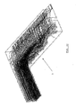
- FIGS 1A to 1C schematically show several examples of execution of the industrial steam generator according to the present invention.
- the Figures 2A and 2B show execution details respectively of the liquid metal crucible and the steam ejector according to a preferred embodiment of the present invention.
- the Figure 2B illustrates in particular the easy system for adapting the steam jet to the width of the strip by simply rotating the ejector about its axis.
- FIGS. 3A to 3C represent several views of the vapor ejector according to the present invention, illustrating a uniform distribution of the vaporized metal.
- the figures 4 and 5 represent simulation results in fluid mechanics for the aforementioned evaporation chamber (respectively temperature and output speed).
- the figure 6 shows a micrograph obtained for a magnesium deposit on black iron obtained with a pilot plant according to the present invention.
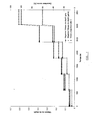
- the figure 7 illustrates an example of regulating the opening of the valves in the installation according to the invention, as well as the corresponding average deposition rate, over time for a liquid magnesium temperature equal to 690 ° C.
- the figure 8 schematically represents a steam generator according to the invention in an embodiment for depositing an alloy of two pure metals on the substrate.
- the solution recommended according to the present invention consists in using an evaporation crucible which is dissociated from a longitudinal vapor outlet evaporation head JVD, hereinafter referred to as an ejector.
- the general principle of such a device is represented on the Figure 1A .
- Another schematic representation is given on the Figure 1B .
- the overall description of a pilot plant is given to the figure 1C .
- the crucible 1 is fed via a pipe 1A from a magnesium 2 melting furnace, with settling of the impurities.
- the type of melting furnace and the pipes used are materials usually used in the foundry industry and well known to those skilled in the art.
- the fusion and the loading in the apparatus according to the invention are done by proven techniques.
- the crucible 1 being remote and of cylindrical shape, a good uniformity of temperature can be reached thanks to a large magnetic stirring.
- the magnetic stirring provided by an inductor 1B mounted on this crucible makes it possible to maintain homogeneity throughout the crucible, the segregations of non-evaporated impurities (settling and flotation) occurring in the melting furnace 2. This ensures consistency in the time evaporation conditions and therefore deposition.
- Brewing Magnetic is adjusted by the induction frequency depending on the nature of the crucible and its size.
- the remote crucible is connected to the ejector 3 (double on the Figure 1A ), which is in the vacuum chamber 6 in which the metal strip 7 passes, by a cylindrical pipe 4, whose section is dimensioned to obtain a slow speed (the speed at the outlet of the crucible is ideally of the order from meters per second to tens of meters per second).
- the figure 7 illustrates the use of such a butterfly valve 5, possibly with a pressure drop device 5A, for the regulation of the steam flow. Mass flow rates are constant for a given valve position and transients are almost non-existent.
- Another important advantage is that the entire outside of the vacuum chamber 6 is accessible, the disadvantage being however the mandatory achievement of vacuum tightness and high temperature at the junctions in the remote part (not shown).
- an external radiating furnace is used (of the cylindrical furnace type with wires or radiating resistors).
- Such ovens are used in the laboratory up to a temperature of 1400-1500 ° C. This oven is very robust since the usual working temperature for this application is of the order of 700 ° C.
- a cylindrical crucible 1, containing molten magnesium is relocated out of the tank 6 and in communication with a head JVD, as a magnesium vapor ejector having an exit slot arranged transversely over the entire width of the strip.
- the latter can be arranged indifferently vertical or horizontal.
- the magnesium is pumped from the melting furnace to the crucible by means of a pump, but can also be done more easily by depression, the pressure of the crucible then being lower than that of the melting furnace.
- the regulation means and the instrumentation are arranged out of vacuum.
- the advantage of this device is that there is no liquid magnesium stored in the deposition tank, which reduces the inertia or segregation of impurity particles under vacuum.
- the pipe 4 of vapor transfer is equipped with a heating.
- This organ also ensures the filtration and the heating of the vapor that passes through it.
- this filter medium may be a sintered titanium filter.
- the crucible 1 according to a preferred form of the invention shown in detail on the Figure 2A , is unique and is easily accessible for any maintenance intervention. It is inert at high temperature contact with the liquid metal for its inner surface and resistant to air oxidation for its outer surface. It will preferably be coated stainless steel or any material compatible with the metal to be evaporated and with the contact with air at high temperature, for its outer part. For example, in the case of magnesium, it will be possible to choose a soft stainless steel-iron colaminate.
- the heating of the crucible 1 is conventional and carried out by induction 1B.
- the frequency is advantageously between 400 and 1000 Hz.
- characteristics of the device used are a rise in temperature of 20 min, direct heating rate of magnesium> 60%, a stirring speed> 1 m / s, etc.
- the thermal inertia is reduced.
- the device is provided with a purge of the crucible towards the melting furnace by gravity flow or pumping, in case of problem (not shown).
- the regulation of the magnesium level in the crucible is advantageously carried out by means of mass measurement (pesons).
- the ejector 3 is shown in detail on the Figures 2B and 3A to 3C .
- This is a box longer than the width of the strip to be coated.
- This device contains a filter medium or creating a pressure drop 3A and thus ensuring the uniform flow of steam over the entire length of the box.
- the ejector 3 is heated to a temperature higher than that of the metal vapor and is insulated externally. The heating may be internal by cartridges (choice adopted in the present embodiment) but may also be external by radiating resistors.
- a calibrated slot provides the projection, at the speed of sound, of the metal vapor on the band 7. The sonic neck over the entire length of the slot very effectively completes the filter medium 3A to ensure the uniformity of the deposit on the tape.
- the adaptation to the width of the strip 7 is done by rotating the ejector around its supply line 3B.
- the Figure 2B represents the internal mechanics of the deposition tank which is then very simplified and reliable.
- the regulation of the steam flow is ensured by the valve 5 situated on the circular pipe 4 (see Figure 1B ).
- the figure 7 illustrates an example of regulation that can be performed.
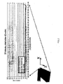
- Table 1 gives the parameters of a pilot plant produced for the implementation of the invention, in comparison with the parameters of a typical industrial installation in the context of a magnesium deposition application.
- Table 1 Industrial solution Pilot solution Diameter crucible 650 mm 265 mm Generator height 1000mm 500 mm driven diameters 250 mm 100 mm Working temperature 690 - 750 ° C 690 - 750 ° C Wall temperatures 750 ° C 750 ° C Working pressure 30 to 70 mbar 30 to 70 mbar Induction power 160 kW 50 kW Extent of work 2.5 2.5 Liquid metal volume 82 L 18L Ejector 1600 mm 450 mm Slot 10 mm 5 mm Ejector pressure qques mmbar qques mmbar
- FIGS. 3A to 3C show different perspective views of the ejector 3 with its sintered titanium filter 3A and the ejection slot 3B.
- the figure 3C shows a simulation of the vapor trajectories in the ejection head.
- results of a numerical simulation in fluid mechanics, applied to the ejector, are represented on the figures 4 and 5 .
- the differences in vapor temperature before and after the sintered filter are very small (0.103K, see figure 4 ).
- the velocity distribution along the central exit line is practically constant, the direction of velocity not significantly varying except near the end of the head ( figure 5 ).
- the steam jet is almost perfectly uniform and isothermal.
- the metal vapor deposition on the strip will be uniform in thickness and crystalline structure.
- the figure 6 shows, at different magnifications, the coating of a black iron sample with magnesium, obtained with the aforementioned pilot plant. We can see the good homogeneity of the deposit.
- the remote device according to the invention is particularly suitable for depositing alloy by steam mixing because it allows to adjust the deposited chemical composition without having to modify the composition of a liquid alloy.
- the mixture is then in a pipe at a very low flow rate contrary to the state of the art.
- two melting chambers 11, 12 respectively containing two different pure metals are each connected by a pipe 4, 4 'provided with a valve 5, 5' to a mixing chamber coupled to the ejector 3.
- the concentration of the two metals in the mixture is adjusted by means of the respective proportional valves 5, 5 ', which simplifies the management problem.
- the size of this system is advantageously reduced.
- a pressure drop system 5A is used on each pipe, cooperating with the respective valves, which allows a good magnetic stirring and obtaining a higher pressure steam in the absence of this system (ex. 20 mbar at 700 ° C).
- This device also makes it possible to regulate the flow of steam in a fine and rapid manner.
- the system according to the invention makes it possible to obtain a very good uniformity of the temperature and the velocity of the vapor deposited, while being reliable and accessible and having very short response times.
- the invention thus very well meets the industrialization requirements of the process.
- Low frequency control of the induction heating ensures a very good uniformity in composition and temperature in the crucible and the regulation of the steam flow is done simply by means of a valve located at the level of the pipe connecting the evaporation crucible. and the deposit ejector and adjusting the energy transmitted to the metal.
- the regulation of the level of liquid under vacuum, including inside the evaporation chamber is carried out by means of a magnetohydrodynamic pump.
- the level regulation according to the invention is done by weighing the crucible and the dispensing chamber according to the invention is a JVD system provided with a slot containing only the vapor of the metal to be deposited. .
Landscapes
- Chemical & Material Sciences (AREA)
- Chemical Kinetics & Catalysis (AREA)
- Engineering & Computer Science (AREA)
- Materials Engineering (AREA)
- Mechanical Engineering (AREA)
- Metallurgy (AREA)
- Organic Chemistry (AREA)
- Physical Vapour Deposition (AREA)
Abstract
Description
La présente invention se rapporte à un générateur de vapeur industriel pour revêtir sous vide et en continu un substrat en mouvement, plus particulièrement une bande métallique, au moyen d'une vapeur métallique en vue de former une couche de métal et de préférence une couche d'alliage métallique sur sa surface, de manière à lui assurer une excellente résistance à la corrosion tout en conservant de bonnes caractéristiques d'emboutissage et de soudabilité.The present invention relates to an industrial steam generator for continuously vacuum coating a moving substrate, more particularly a metal strip, by means of a metal vapor to form a layer of metal and preferably a layer of metal. metal alloy on its surface, so as to ensure excellent resistance to corrosion while maintaining good characteristics of stamping and weldability.
Il est connu depuis la fin des années 1980 que le dépôt de certains alliages, tels que ZnMg, à la surface d'une bande d'acier, a un rôle protecteur de l'acier. L'excellente tenue en corrosion de l'alliage ZnMg est attribuée à la nature des produits de corrosion formés à la surface de la bande selon une couche extrêmement dense jouant le rôle de film-barrière.It has been known since the end of the 1980s that the deposition of certain alloys, such as ZnMg, on the surface of a steel strip, has a protective role for steel. The excellent corrosion performance of the ZnMg alloy is attributed to the nature of the corrosion products formed on the surface of the strip in an extremely dense layer acting as a barrier film.
Un tel dépôt d'alliage n'est généralement pas possible au moyen des techniques habituelles telles que le dépôt électrolytique, le revêtement au trempé, etc. Ainsi, à la pression atmosphérique, on peut avoir contamination du bain de métal liquide par l'oxygène de l'air, qui forme des oxydes à la surface du bain.Such alloy deposition is generally not possible using conventional techniques such as electroplating, dip coating, etc. Thus, at atmospheric pressure, the liquid metal bath can be contaminated by oxygen in the air, which forms oxides on the surface of the bath.
La seule issue possible est donc souvent l'évaporation sous vide du métal liquide, pur ou sous forme d'alliage (technique PVD, Pressure Vapor Deposition).The only possible solution is therefore vacuum evaporation of the liquid metal, pure or in the form of an alloy (PVD technique, Pressure Vapor Deposition ).
Dans le cadre de cette technique, il est connu de placer le substrat dans une enceinte sous vide maintenue à basse température et contenant un creuset de métal fondu. Le dépôt s'effectue alors sur toutes les parois dont la température est inférieure à la température de la vapeur métallique. Pour augmenter le rendement de dépôt sur le substrat et éviter les gaspillages, on a donc intérêt à chauffer les parois de l'enceinte.In the context of this technique, it is known to place the substrate in a vacuum chamber maintained at low temperature and containing a molten metal crucible. The deposition then takes place on all the walls whose temperature is lower than the temperature of the metal vapor. To increase the deposition efficiency on the substrate and avoid wastage, it is therefore advantageous to heat the walls of the enclosure.
Le document
Dans le document
Dans le document
Dans le document
La Demanderesse a en outre proposé un produit industriel bicouche électro-zingué/alliage ZnMg obtenu par la voie PVD (
Dans le document
Cette technologie présente cependant plusieurs défauts, dont notamment :
- l'alimentation permanente en métal liquide implique de prévoir le retour à la cuve de celui-ci en un ou plusieurs points ;
- le métal liquide comprenant des impuretés, il y a concentration de ces impuretés en surface du bain suite à l'évaporation, ce qui réduit le débit. Une solution serait un écrémage de la surface ou un recyclage de la charge mais toute opération mécanique est rendue difficile sous vide ;
- la difficulté d'adapter la fente d'évaporation à une largeur de bande variable, ce qui implique des moyens d'occultation de part et d'autre de la fente, et partant la réalisation d'une étanchéité à la vapeur sous vide et à 700°C, ce qui n'est pas aisé à réaliser ;
- la difficulté d'occulter la fente lorsque le mouvement de la bande s'interrompt, ce qui impliquerait la présence d'une vanne linéaire étanche sur une longueur typique de 2 mètres ou plus ;
- la grande inertie thermique du système (au moins plusieurs minutes) ;
- le chauffage, réalisé par induction sous vide, nécessite de passer toute la puissance électrique de chauffage au travers de la paroi étanche au vide, ce qui ne facilite pas l'accessibilité et la maintenabilité de l'installation.
- the permanent supply of liquid metal involves providing for the return to the tank thereof at one or more points;
- the liquid metal comprising impurities, there is concentration of these impurities at the surface of the bath following evaporation, which reduces the flow rate. One solution would be skimming the surface or recycling the load but any mechanical operation is made difficult under vacuum;
- the difficulty of adapting the evaporation slot to a variable bandwidth, which implies means of concealment on both sides of the slot, and thus the realization of a vapor seal under vacuum and 700 ° C, which is not easy to achieve;
- the difficulty of concealing the slot when the movement of the band is interrupted, which would imply the presence of a tight linear valve on a typical length of 2 meters or more;
- the great thermal inertia of the system (at least several minutes);
- the heating, carried out by induction under vacuum, requires passing all the electrical heating power through the vacuum-tight wall, which does not facilitate the accessibility and maintainability of the installation.
Par ailleurs, l'état de la technique n'apporte pas de solution satisfaisante à la nécessité de réaliser le co-dépôt de deux métaux distincts, impliquant le mélange de deux jets en sortie de l'évaporateur. L'utilisation de boîtes de mélange intermédiaires à chicanes n'a apporté aucun résultat probant.Furthermore, the state of the art does not provide a satisfactory solution to the need to co-deposit two separate metals, involving the mixing of two jets at the outlet of the evaporator. The use of intermediate baffling mixing boxes did not bring any convincing results.
Il est possible de réaliser des alliages de métal de revêtement (ex. 85% Zn, 15% Mg) en contrôlant rigoureusement la concentration des deux métaux dans le creuset. Toutefois ce contrôle implique de grandes difficultés de gestion du système, et en particulier l'homogénéité dans le creuset, surtout si celui-ci n'est pas de section circulaire.Coating metal alloys (eg 85% Zn, 15% Mg) can be made by tightly controlling the concentration of both metals in the crucible. However, this control involves great difficulties of management of the system, and in particular the homogeneity in the crucible, especially if it is not of circular section.
On sait aussi que la société Sidrabe Inc. (Lettonie) a proposé par ailleurs un procédé PVD où la source de métal en fusion est déportée en dehors de la chambre de dépôt sous vide, initialement pour éviter qu'à haute vitesse d'évaporation, de fines particules de magnésium solide ne se déposent sur le substrat. La séparation de la zone de fusion de la boîte d'évaporation par une conduite de communication permet de réguler plus aisément l'évaporation. Une mesure de pression de vapeur est notamment effectuée au niveau de cette conduite (par ex. dans
Le document
La présente invention vise à fournir une solution qui permette de s'affranchir des inconvénients de l'état de la technique.The present invention aims to provide a solution that makes it possible to overcome the disadvantages of the state of the art.
En particulier, l'invention vise à atteindre notamment les objectifs suivants :
- simplicité de réalisation ;
- accessibilité et maintenance aisées du ou des creusets ;
- excellente uniformité de l'évaporation et mécanisme simple d'adaptation sur des largeurs de bande pouvant excéder 2 mètres ;
- débit de vapeur maximalisé ;
- brassage magnétique élevé évitant la ségrégation des impuretés en surface ;
- régulation aisée du débit de vapeur, par contrôle de la puissance électrique et/ou de la température de surface d'évaporation ;
- installation possible et facilité procurée par des vannes dans des conduites cylindriques de diamètre réduit.
- simplicity of realization;
- easy access and maintenance of the crucible (s);
- excellent uniformity of evaporation and simple mechanism of adaptation on bandwidths exceeding 2 meters;
- maximized vapor flow;
- high magnetic stirring avoiding the segregation of impurities on the surface;
- easy regulation of the steam flow by controlling the electric power and / or the evaporation surface temperature;
- possible installation and ease provided by valves in cylindrical pipes of reduced diameter.
La présente invention se rapporte à un générateur de vapeur pour le dépôt d'un revêtement métallique sur un substrat, de préférence une bande d'acier, comprenant une chambre à vide sous forme d'une enceinte, munie de moyens pour y assurer un état de dépression par rapport au milieu extérieur et munie de moyens permettant l'entrée et la sortie du substrat, tout en étant essentiellement étanche par rapport au milieu extérieur, ladite enceinte englobant une tête de dépôt de vapeur, appelée éjecteur, conformé pour créer un jet de vapeur métallique à la vitesse sonique en direction de et perpendiculaire à la surface du substrat, ledit éjecteur étant en communication de manière étanche au moyen d'une conduite d'alimentation avec au moins un creuset contenant un métal de revêtement sous forme liquide et situé à l'extérieur de la chambre à vide, caractérisé en ce que ledit générateur de vapeur comprend des moyens pour réguler le débit, la pression et/ou la vitesse de la vapeur métallique dans l'éjecteur.The present invention relates to a steam generator for depositing a metal coating on a substrate, preferably a steel strip, comprising a vacuum chamber in the form of an enclosure, provided with means to ensure a state depression relative to the external medium and provided with means for the entry and exit of the substrate, while being essentially sealed with respect to the external environment, said enclosure including a vapor deposition head, called ejector, shaped to create a jet of metal vapor at sonic velocity in the direction of and perpendicular to the surface of the substrate, said ejector being in sealing communication by means of a feed pipe with at least one crucible containing a coating metal in liquid form and located outside the vacuum chamber, characterized in that said steam generator comprises means for regulating the flow, the pressure and / or the speed of the metal vapor in the ejector.
Selon l'invention, lesdits moyens de régulation comprennent une vanne et/ou un dispositif de perte de charge disposés dans ladite conduite.According to the invention, said regulating means comprise a valve and / or a pressure drop device disposed in said pipe.
Avantageusement, la vanne est une vanne proportionnelle, de préférence de type papillon.Advantageously, the valve is a proportional valve, preferably butterfly type.
De préférence, l'éjecteur comprend une fente longitudinale de sortie de la vapeur, jouant le rôle de col sonique, s'étendant sur toute la largeur du substrat et un milieu filtrant pouvant être un filtre fritté, de préférence en titane, de sorte à uniformiser et redresser les vecteurs vitesse de la vapeur sortant de la tête de dépôt.Preferably, the ejector comprises a longitudinal steam exit slot, acting as a sonic neck, extending over the entire width of the substrate and a filtering medium which can be a sintered filter, preferably made of titanium, so as to standardize and straighten the velocity vectors of the vapor leaving the deposition head.
Avantageusement, le générateur comporte des moyens pour ajuster la longueur de la fente à la largeur du substrat, ces moyens comprenant par exemple des moyens de rotation de l'éjecteur autour de sa conduite d'alimentation.Advantageously, the generator comprises means for adjusting the length of the slot to the width of the substrate, these means comprising for example means for rotating the ejector around its supply line.
Selon une forme d'exécution alternative, le générateur de vapeur selon l'invention comporte un creuset contenant un mélange de métaux sous forme liquide.According to an alternative embodiment, the steam generator according to the invention comprises a crucible containing a mixture of metals in liquid form.
Toujours selon l'invention, le creuset est alimenté par pompage ou par gravité du métal liquide à partir d'un four de fusion.Still according to the invention, the crucible is fed by pumping or gravity of the liquid metal from a melting furnace.
Avantageusement, le creuset comporte une purge vers le four de fusion par pompage ou écoulement gravitaire.Advantageously, the crucible comprises a purge to the melting furnace by pumping or gravity flow.
Toujours avantageusement, le creuset comporte des moyens de mesure de niveau. Une mesure de masse extérieure au creuset et un moyen qui a été utilisé selon l'invention pour réguler le niveau de métal liquide.Still advantageously, the crucible comprises means for level measurement. A mass measurement external to the crucible and a means which has been used according to the invention to regulate the level of liquid metal.
Selon une modalité d'exécution préférée de l'invention, l'éjecteur, la conduite et le creuset sont isolés thermiquement du milieu extérieur et chauffés par un four à rayonnement extérieur à ces organes. La chambre à vide peut rester froide ou maintenue chaude.According to a preferred embodiment of the invention, the ejector, the pipe and the crucible are thermally insulated from the external environment and heated by a radiation oven outside these organs. The vacuum chamber can stay cool or kept warm.
Selon une autre modalité d'exécution de l'invention, le générateur de vapeur comporte deux creusets contenant des métaux sous forme liquide différents, en vue de réaliser un dépôt d'alliage métallique sur le substrat.According to another embodiment of the invention, the steam generator comprises two crucibles containing different metals in liquid form, for producing a metal alloy deposit on the substrate.
Selon l'invention, chaque creuset est relié par une conduite propre à un mélangeur, lui-même en communication avec l'éjecteur.According to the invention, each crucible is connected by a clean pipe to a mixer, itself in communication with the ejector.
Avantageusement, chaque conduite comporte une vanne et/ou un dispositif de perte de charge permettant l'ajustement des concentrations de chaque métal lors du mélange des vapeurs à déposer sur le substrat.Advantageously, each pipe comprises a valve and / or a pressure drop device for adjusting the concentrations of each metal during the mixing of the vapors to be deposited on the substrate.
Selon une modalité préférée, le mélangeur est l'éjecteur lui-même et comporte un milieu filtrant pouvant être un filtre fritté permettant d'uniformiser et redresser les vecteurs vitesse de la vapeur de chaque métal sortant de l'éjecteur.According to a preferred embodiment, the mixer is the ejector itself and comprises a filter medium which can be a sintered filter for uniformizing and straightening the velocity vectors of the vapor of each metal leaving the ejector.
Les
Les
Les
Les
La
La
La
La solution préconisée selon la présente invention consiste à utiliser un creuset d'évaporation qui soit dissocié d'une tête d'évaporation JVD à fente longitudinale de sortie de vapeur, appelée ci-après éjecteur. Le principe général d'un tel dispositif est représenté sur la
Le creuset 1 étant déporté et de forme cylindrique, une bonne uniformité de température peut être atteinte grâce à un brassage magnétique important. Le brassage magnétique assuré par un inducteur 1B monté sur ce creuset permet de conserver une homogénéité dans tout le creuset, les ségrégations d'impuretés non évaporées (décantation et flottaison) se faisant dans le four de fusion 2. On assure ainsi la constance dans le temps des conditions d'évaporation et donc de dépôt. Le brassage magnétique est ajusté par la fréquence d'induction en fonction de la nature du creuset et de sa taille.The
Le creuset déporté est relié à l'éjecteur 3 (double sur la
L'utilisation d'une conduite cylindrique permet d'obtenir une bonne étanchéité à haute température et au vide en utilisant par exemple une vanne papillon 5 telle que disponible dans le commerce.The use of a cylindrical pipe makes it possible to obtain a good seal at high temperature and at a vacuum, for example using a butterfly valve as commercially available.
La
Un autre avantage important est que toute la partie extérieure à l'enceinte sous vide 6 est accessible, le désavantage étant cependant la réalisation obligatoire de l'étanchéité au vide et à haute température au niveau des jonctions dans la partie déportée (non représenté).Another important advantage is that the entire outside of the
Pour chauffer le creuset, la conduite et l'éjecteur, on utilise un four extérieur par rayonnement (de type four cylindrique à fils ou résistances rayonnants). De tels fours sont utilisés en laboratoire jusqu'à une température de 1400-1500°C. Ce four est donc très robuste vu que la température de travail habituelle pour cette application est de l'ordre de 700°C.To heat the crucible, the pipe and the ejector, an external radiating furnace is used (of the cylindrical furnace type with wires or radiating resistors). Such ovens are used in the laboratory up to a temperature of 1400-1500 ° C. This oven is very robust since the usual working temperature for this application is of the order of 700 ° C.
Grâce à ce four à rayonnement, la vapeur est surchauffée, ce qui permet de s'éloigner de la température de pression de vapeur saturante et donc du point de condensation. Le risque de recondensation diminue donc. De plus, des simulations numériques ont été effectuées pour déterminer la gamme des vitesses permettant d'éviter la détente adiabatique et donc la condensation suite à la diminution de température qui en découle.Thanks to this radiation oven, the steam is superheated, which makes it possible to move away from the saturation vapor pressure temperature and thus the condensation. The risk of recondensation therefore decreases. In addition, numerical simulations have been carried out to determine the range of speeds to avoid adiabatic expansion and therefore condensation following the decrease in temperature that results.
Le fait d'utiliser un chauffage par l'extérieur de la chambre à vide, avec calorifugeage approprié, présente un certain nombre d'avantages :
- maintenance aisée du système de chauffage ;
- isolation et calorifugeage se trouvant à l'extérieur de la chambre à vide, limitant les phénomènes de dégazage sous vide ;
- réduction des problèmes liés à l'utilisation d'éléments chauffants sous vide et liés au refroidissement de leurs connexions électriques ;
- limitation du nombre de cartouches de chauffage sous vide à l'éjecteur, avec limite d'utilisation plus haute (meilleure tenue dans le temps). Par exemple deux cartouches de chauffage à 1100°C sont suffisantes dans le cas du chauffage par rayonnement ;
- utilisation de techniques de chauffage et d'éléments de chauffage robustes et fiables.
- easy maintenance of the heating system;
- insulation and insulation located outside the vacuum chamber, limiting vacuum degassing phenomena;
- reducing the problems associated with the use of vacuum heaters and cooling their electrical connections;
- limitation of the number of vacuum heating cartridges to the ejector, with higher use limit (better durability). For example, two heating cartridges at 1100 ° C are sufficient in the case of radiant heating;
- use of robust and reliable heating techniques and heating elements.
Selon une forme d'exécution préférée de l'invention, représentée sur la
L'avantage de ce dispositif est qu'il n'y a pas de magnésium liquide stocké dans la cuve de dépôt, ce qui réduit les inerties, ni de ségrégation de particules d'impuretés sous vide. La conduite 4 de transfert de vapeur est équipée d'un chauffage. La répartition de la vapeur de magnésium sur la largeur de la bande (avant la fente d'éjection) et assurée par un milieu filtrant 3A situé dans l'éjecteur. Cet organe assure en outre la filtration et le réchauffement de la vapeur qui le traverse. Par exemple, ce milieu filtrant peut être un filtre en titane fritté.The advantage of this device is that there is no liquid magnesium stored in the deposition tank, which reduces the inertia or segregation of impurity particles under vacuum. The
Le creuset 1 selon une forme préférée de l'invention représentée en détail sur la
Il sera de préférence en inox revêtu ou en tout matériau compatible avec le métal à évaporer et avec le contact à l'air à haute température, pour sa partie extérieure. On pourra ainsi choisir par exemple dans le cas du magnésium un colaminé inox-fer doux.The
It will preferably be coated stainless steel or any material compatible with the metal to be evaporated and with the contact with air at high temperature, for its outer part. For example, in the case of magnesium, it will be possible to choose a soft stainless steel-iron colaminate.
Le chauffage du creuset 1 est conventionnel et réalisé par induction 1B. La fréquence est avantageusement comprise entre 400 et 1000 Hz. D'autres caractéristiques du dispositif mis en oeuvre sont une montée en température de 20 min, taux de chauffage direct du magnésium > 60%, une vitesse de brassage > 1 m/s, etc.The heating of the
L'inertie thermique est réduite. Le dispositif est pourvu d'une purge du creuset vers le four de fusion par écoulement gravitaire ou pompage, en cas de problème (non représenté).The thermal inertia is reduced. The device is provided with a purge of the crucible towards the melting furnace by gravity flow or pumping, in case of problem (not shown).
La régulation du niveau de magnésium dans le creuset est avantageusement réalisée par des moyens de mesure de masse (pesons).The regulation of the magnesium level in the crucible is advantageously carried out by means of mass measurement (pesons).
L'éjecteur 3 est représenté en détail sur les
Le tableau 1 donne les paramètres d'une installation pilote réalisée pour la mise en oeuvre de l'invention, en comparaison avec les paramètres d'une installation industrielle typique dans le cadre d'une application de dépôt de magnésium.
Les
Des résultats d'une simulation numérique en mécanique des fluides, appliquée à l'éjecteur, sont représentés sur les
La
D'autre part, le dispositif déporté selon l'invention est particulièrement adapté au dépôt d'alliage par mélange de vapeur car il permet d'ajuster la composition chimique déposée sans avoir à modifier la composition d'un alliage liquide. Le mélange se fait alors dans une conduite à très basse vitesse d'écoulement contrairement à l'état de l'art.On the other hand, the remote device according to the invention is particularly suitable for depositing alloy by steam mixing because it allows to adjust the deposited chemical composition without having to modify the composition of a liquid alloy. The mixture is then in a pipe at a very low flow rate contrary to the state of the art.
Comme représenté sur la
Un système de perte de charge 5A est utilisé sur chaque conduite, coopérant avec les vannes respectives, ce qui permet un bon brassage magnétique et l'obtention d'une vapeur à pression plus haute qu'en l'absence de ce système (ex. 20 mbar à 700°C).A
Ce dispositif permet également de réguler le débit de vapeur de façon fine et rapide.This device also makes it possible to regulate the flow of steam in a fine and rapid manner.
Le système selon l'invention permet l'obtention d'une très bonne uniformité de la température et de la vitesse de la vapeur déposée, tout en étant fiable et accessible et en ayant de très faibles temps de réponse. L'invention répond ainsi très bien aux exigences d'industrialisation du procédé. Une régulation à basse fréquence du chauffage par induction assure une très bonne uniformité en composition et en température dans le creuset et la régulation du débit de vapeur se fait simplement au moyen d'une vanne située au niveau de la conduite reliant le creuset d'évaporation et l'éjecteur de dépôt et en ajustant l'énergie transmise au métal. Dans
Claims (17)
Priority Applications (15)
| Application Number | Priority Date | Filing Date | Title |
|---|---|---|---|
| EP07447056A EP2048261A1 (en) | 2007-10-12 | 2007-10-12 | Industrial steam generator for depositing an alloy coating on a metal band |
| KR1020107007808A KR101530183B1 (en) | 2007-10-12 | 2008-10-10 | Industrial vapour generator for the deposition of an alloy coating onto a metal strip |
| PL08805229T PL2198070T3 (en) | 2007-10-12 | 2008-10-10 | Industrial steam generator for depositing an alloy coating on a metal band |
| MX2010003889A MX2010003889A (en) | 2007-10-12 | 2008-10-10 | Industrial vapour generator for the deposition of an alloy coating onto a metal strip. |
| US12/681,969 US11434560B2 (en) | 2007-10-12 | 2008-10-10 | Industrial vapour generator for the deposition of an alloy coating onto a metal strip |
| AU2008309572A AU2008309572B2 (en) | 2007-10-12 | 2008-10-10 | Industrial vapour generator for the deposition of an alloy coating onto a metal strip |
| PCT/EP2008/063638 WO2009047333A1 (en) | 2007-10-12 | 2008-10-10 | Industrial vapour generator for the deposition of an alloy coating onto a metal strip |
| BRPI0816567-0A BRPI0816567B1 (en) | 2007-10-12 | 2008-10-10 | VAPOR GENERATOR FOR THE DEPOSITION OF A METAL COATING ON A SUBSTRATE |
| RU2010118090/02A RU2429312C1 (en) | 2007-10-12 | 2008-10-10 | Industrial steam generator for application of coating out of alloy on metal tape |
| ES08805229.5T ES2647215T3 (en) | 2007-10-12 | 2008-10-10 | Industrial steam generator for depositing an alloy coating on a metal strip |
| HUE08805229A HUE035305T2 (en) | 2007-10-12 | 2008-10-10 | Industrial steam generator for depositing an alloy coating on a metal band |
| CN2008801158960A CN101855380B (en) | 2007-10-12 | 2008-10-10 | Industrial vapour generator for the deposition of an alloy coating onto a metal strip |
| EP08805229.5A EP2198070B1 (en) | 2007-10-12 | 2008-10-10 | Industrial steam generator for depositing an alloy coating on a metal band |
| UAA201005707A UA94675C2 (en) | 2007-10-12 | 2008-10-10 | INDUSTRIAL vapour generator for the deposition of a metal coating from the melt onto a substrate |
| CA2702188A CA2702188C (en) | 2007-10-12 | 2008-10-10 | Industrial vapour generator for the deposition of an alloy coating onto a metal strip |
Applications Claiming Priority (1)
| Application Number | Priority Date | Filing Date | Title |
|---|---|---|---|
| EP07447056A EP2048261A1 (en) | 2007-10-12 | 2007-10-12 | Industrial steam generator for depositing an alloy coating on a metal band |
Publications (1)
| Publication Number | Publication Date |
|---|---|
| EP2048261A1 true EP2048261A1 (en) | 2009-04-15 |
Family
ID=39262566
Family Applications (2)
| Application Number | Title | Priority Date | Filing Date |
|---|---|---|---|
| EP07447056A Withdrawn EP2048261A1 (en) | 2007-10-12 | 2007-10-12 | Industrial steam generator for depositing an alloy coating on a metal band |
| EP08805229.5A Active EP2198070B1 (en) | 2007-10-12 | 2008-10-10 | Industrial steam generator for depositing an alloy coating on a metal band |
Family Applications After (1)
| Application Number | Title | Priority Date | Filing Date |
|---|---|---|---|
| EP08805229.5A Active EP2198070B1 (en) | 2007-10-12 | 2008-10-10 | Industrial steam generator for depositing an alloy coating on a metal band |
Country Status (14)
| Country | Link |
|---|---|
| US (1) | US11434560B2 (en) |
| EP (2) | EP2048261A1 (en) |
| KR (1) | KR101530183B1 (en) |
| CN (1) | CN101855380B (en) |
| AU (1) | AU2008309572B2 (en) |
| BR (1) | BRPI0816567B1 (en) |
| CA (1) | CA2702188C (en) |
| ES (1) | ES2647215T3 (en) |
| HU (1) | HUE035305T2 (en) |
| MX (1) | MX2010003889A (en) |
| PL (1) | PL2198070T3 (en) |
| RU (1) | RU2429312C1 (en) |
| UA (1) | UA94675C2 (en) |
| WO (1) | WO2009047333A1 (en) |
Cited By (6)
| Publication number | Priority date | Publication date | Assignee | Title |
|---|---|---|---|---|
| EP2199425A1 (en) * | 2008-12-18 | 2010-06-23 | ArcelorMittal France | Industrial steam generator for depositing any alloy coating on a metal band (II) |
| US20110315078A1 (en) * | 2010-06-29 | 2011-12-29 | Hon Hai Precision Industry Co., Ltd. | Coating system |
| WO2012095489A1 (en) | 2011-01-14 | 2012-07-19 | Arcelormittal Investigacion Y Desarrollo | Automatic feeding device for an industrial metal-vapor generator |
| US10400326B2 (en) | 2013-08-01 | 2019-09-03 | Arcelormittal Sa | Painted steel sheet provided with a zinc coating |
| WO2019239184A1 (en) | 2018-06-13 | 2019-12-19 | Arcelormittal | Vacuum deposition facility and method for coating a substrate |
| WO2019239185A1 (en) | 2018-06-13 | 2019-12-19 | Arcelormittal | Vacuum deposition facility and method for coating a substrate |
Families Citing this family (33)
| Publication number | Priority date | Publication date | Assignee | Title |
|---|---|---|---|---|
| FR2891135B1 (en) | 2005-09-23 | 2008-09-12 | Ldr Medical Sarl | INTERVERTEBRAL DISC PROSTHESIS |
| US20110177622A1 (en) * | 2009-12-28 | 2011-07-21 | Global Solar Energy, Inc. | Apparatus and methods of mixing and depositing thin film photovoltaic compositions |
| WO2011080535A1 (en) | 2009-12-31 | 2011-07-07 | Lrd Medical | Anchoring device, intervertebral implant and implantation instrument |
| EP2369033A1 (en) * | 2010-03-26 | 2011-09-28 | Saint-Gobain Glass France | Method for refilling an evaporation chamber |
| KR101671489B1 (en) * | 2010-07-29 | 2016-11-02 | 삼성디스플레이 주식회사 | Evaporation source for organic material and vapor depositing apparatus including the same |
| CN103249860B (en) * | 2010-12-13 | 2016-03-16 | Posco公司 | Continuous coating apparatus |
| EP2794951B1 (en) | 2011-12-23 | 2019-03-06 | Tata Steel Nederland Technology B.V. | Substrate with a double layered coating |
| FR2987256B1 (en) | 2012-02-24 | 2014-08-08 | Ldr Medical | ANCHORING DEVICE FOR INTERVERTEBRAL IMPLANT, INTERVERTEBRAL IMPLANT AND IMPLANTATION INSTRUMENTATION |
| KR102053249B1 (en) * | 2013-05-02 | 2020-01-09 | 삼성디스플레이 주식회사 | Deposition source and deposition apparatus including the same |
| FR3005569B1 (en) | 2013-05-16 | 2021-09-03 | Ldr Medical | VERTEBRAL IMPLANT, VERTEBRAL IMPLANT FIXATION DEVICE AND IMPLANTATION INSTRUMENTATION |
| UA116262C2 (en) * | 2013-08-01 | 2018-02-26 | Арселорміттал | Zinc Coated Steel Sheet |
| KR102242070B1 (en) * | 2013-11-05 | 2021-04-20 | 타타 스틸 네덜란드 테크날러지 베.뷔. | Method and apparatus for controlling the composition of liquid metal in an evaporator device |
| MX2014013233A (en) * | 2014-10-30 | 2016-05-02 | Ct Investig Materiales Avanzados Sc | Injection nozzle for aerosols and their method of use to deposit different coatings via vapor chemical deposition assisted by aerosol. |
| US20190048460A1 (en) * | 2017-08-14 | 2019-02-14 | Wuhan China Star Optoelectronics Semiconductor Display Technology Co., Ltd. | Evaporation Crucible and Evaporation System |
| CN107400860B (en) * | 2017-09-08 | 2020-06-26 | 三河市衡岳真空设备有限公司 | High-frequency induction heating evaporation device |
| WO2019239186A1 (en) * | 2018-06-13 | 2019-12-19 | Arcelormittal | Vacuum deposition facility and method for coating a substrate |
| WO2019239192A1 (en) | 2018-06-15 | 2019-12-19 | Arcelormittal | Vacuum deposition facility and method for coating a substrate |
| CN109881156A (en) * | 2019-04-15 | 2019-06-14 | 湖畔光电科技(江苏)有限公司 | A kind of evaporation source preventing material degradation |
| EP3786311A1 (en) * | 2019-08-30 | 2021-03-03 | Theva Dünnschichttechnik GmbH | Device, method and system for coating a substrate, especially a superconducting conductor strip and coated superconducting conductor strip |
| CN112538603A (en) * | 2019-09-23 | 2021-03-23 | 宝山钢铁股份有限公司 | Vacuum coating device capable of continuously filling and continuous filling method thereof |
| CN112553577A (en) * | 2019-09-26 | 2021-03-26 | 宝山钢铁股份有限公司 | Vacuum coating device for improving vacuum coating yield |
| CN112553578B (en) * | 2019-09-26 | 2022-01-14 | 宝山钢铁股份有限公司 | Vacuum coating device with flow-inhibiting nozzle |
| CN112575308B (en) * | 2019-09-29 | 2023-03-24 | 宝山钢铁股份有限公司 | Vacuum coating device capable of efficiently coating strip steel under vacuum |
| CN113564534B (en) * | 2020-04-28 | 2023-05-09 | 宝山钢铁股份有限公司 | Continuous plating solution supply device and method for vacuum plating unit |
| CN113684479A (en) * | 2020-05-19 | 2021-11-23 | 宝山钢铁股份有限公司 | Coating method using electromagnetic stirrer for stirring and alloy vacuum deposition device |
| CN113930738B (en) * | 2020-06-29 | 2023-09-12 | 宝山钢铁股份有限公司 | Metal vapor modulation device for vacuum coating and modulation method thereof |
| US11655645B2 (en) | 2020-09-25 | 2023-05-23 | Pool Walls LLC | Pool wall assemblies, systems, and methods thereof |
| DE102021100060A1 (en) | 2021-01-05 | 2022-07-07 | Thyssenkrupp Steel Europe Ag | coating arrangement |
| CN113151784A (en) * | 2021-05-17 | 2021-07-23 | 中冶赛迪工程技术股份有限公司 | Nano composite hot galvanizing device for strip, production process and strip production line |
| DE102021117576B4 (en) * | 2021-07-07 | 2023-02-09 | Thyssenkrupp Steel Europe Ag | Coating system for coating an object |
| DE102021117574A1 (en) * | 2021-07-07 | 2023-01-12 | Thyssenkrupp Steel Europe Ag | Coating system for coating a flat object and a method for coating a flat object |
| WO2023062410A1 (en) | 2021-10-14 | 2023-04-20 | Arcelormittal | Vapour nozzle for pvd |
| WO2023067371A1 (en) | 2021-10-19 | 2023-04-27 | Arcelormittal | Surface preparation for jvd |
Citations (7)
| Publication number | Priority date | Publication date | Assignee | Title |
|---|---|---|---|---|
| US5002837A (en) | 1988-07-06 | 1991-03-26 | Kabushiki Kaisha Kobe Seiko Sho | Zn-Mg alloy vapor deposition plated metals of high corrosion resistance, as well as method of producing them |
| EP0730045A2 (en) | 1995-02-28 | 1996-09-04 | Nisshin Steel Co., Ltd. | Steel sheet with Zn-Mg binary coating layer excellent in corrosion resistance and manufacturing method thereof |
| EP0756022A2 (en) | 1995-07-27 | 1997-01-29 | Fraunhofer-Gesellschaft Zur Förderung Der Angewandten Forschung E.V. | Steel sheet protected against corrosion and process for its production |
| WO1997047782A1 (en) | 1996-06-13 | 1997-12-18 | Centre De Recherches Metallurgiques-Centrum Voor Research In De Metallurgie | Method and device for continuous coating of a moving substrate by means of a metallic vapour |
| EP1174526A1 (en) * | 2000-07-17 | 2002-01-23 | Nederlandse Organisatie voor Toegepast Natuurwetenschappelijk Onderzoek TNO | Continuous vapour deposition |
| WO2002014573A1 (en) | 2000-08-11 | 2002-02-21 | Fraunhofer-Gesellschaft zur Förderung der angewandten Forschung e.V. | Corrosion-proofed sheet steel and method for production thereof |
| WO2005116290A1 (en) | 2004-05-27 | 2005-12-08 | Sidrabe, Inc. | Method and apparatus for vacuum deposition by vaporizing metals and metal alloys |
Family Cites Families (34)
| Publication number | Priority date | Publication date | Assignee | Title |
|---|---|---|---|---|
| NL63914C (en) * | 1941-09-16 | |||
| US2564231A (en) * | 1949-06-06 | 1951-08-14 | Earl H Pitney | Liquid level maintainer |
| US2761286A (en) * | 1955-03-18 | 1956-09-04 | Gaines H Billue | Vaporizer for liquid petroleum supply tanks |
| JPS495691B1 (en) * | 1965-03-23 | 1974-02-08 | ||
| JPS5322810A (en) * | 1976-08-16 | 1978-03-02 | Fumio Hori | Method and apparatus for producing metal mg or ca by carbon reduction |
| JPS5811497B2 (en) * | 1978-10-04 | 1983-03-03 | 日本電気株式会社 | Ti↓-Al porous alloy and its manufacturing method |
| US4416421A (en) * | 1980-10-09 | 1983-11-22 | Browning Engineering Corporation | Highly concentrated supersonic liquified material flame spray method and apparatus |
| DE3817513C2 (en) * | 1988-05-24 | 1996-01-25 | Leybold Ag | Device for evaporating metals |
| LU87794A1 (en) * | 1990-08-31 | 1991-02-18 | Hydrolux Sarl | PROPORTIONAL-WEGEVENTIL IN SITZBAUWEISE |
| GB9022836D0 (en) * | 1990-10-19 | 1990-12-05 | British Petroleum Co Plc | Membranes |
| JP3463693B2 (en) * | 1992-10-29 | 2003-11-05 | 石川島播磨重工業株式会社 | Vacuum evaporation equipment for continuous strips |
| DE4310085A1 (en) * | 1993-03-27 | 1994-09-29 | Leybold Ag | Method and device for creating patterns on substrates |
| US5766356A (en) * | 1995-07-06 | 1998-06-16 | Toray Engineering Co., Ltd. | Coating apparatus |
| CN1155051A (en) * | 1996-01-19 | 1997-07-23 | 徐国汉 | Quick steam generator |
| US6423144B1 (en) * | 1996-08-07 | 2002-07-23 | Matsushita Electric Industrial Co., Ltd. | Coating apparatus and coating method |
| US6409839B1 (en) * | 1997-06-02 | 2002-06-25 | Msp Corporation | Method and apparatus for vapor generation and film deposition |
| US6197438B1 (en) * | 1998-03-11 | 2001-03-06 | Roger Faulkner | Foodware with ceramic food contacting surface |
| US5904958A (en) * | 1998-03-20 | 1999-05-18 | Rexam Industries Corp. | Adjustable nozzle for evaporation or organic monomers |
| JP2002515333A (en) * | 1998-05-19 | 2002-05-28 | パンケイク、ユージン、エイ | Pumping coating application system |
| CN2332957Y (en) * | 1998-06-26 | 1999-08-11 | 广州雅图机电有限公司 | Low pressure high temp. steam generator |
| JP3349965B2 (en) * | 1998-11-05 | 2002-11-25 | 松下電器産業株式会社 | Fine particle classification method and apparatus |
| US6202591B1 (en) * | 1998-11-12 | 2001-03-20 | Flex Products, Inc. | Linear aperture deposition apparatus and coating process |
| US7056477B1 (en) * | 2000-02-03 | 2006-06-06 | Cellular Process Chemistry, Inc. | Modular chemical production system incorporating a microreactor |
| US7413714B1 (en) * | 2000-07-16 | 2008-08-19 | Ymc Co. Ltd. | Sequential reaction system |
| US6924004B2 (en) * | 2000-07-19 | 2005-08-02 | Regents Of The University Of Minnesota | Apparatus and method for synthesizing films and coatings by focused particle beam deposition |
| EP1182272A1 (en) * | 2000-08-23 | 2002-02-27 | Cold Plasma Applications C.P.A. | Process and apparatus for continuous cold plasma deposition of metallic layers |
| US20030196680A1 (en) * | 2002-04-19 | 2003-10-23 | Dielectric Systems, Inc | Process modules for transport polymerization of low epsilon thin films |
| FR2825450B1 (en) * | 2001-05-31 | 2004-01-16 | Centre Nat Rech Scient | LOW PRESSURE PARTIAL SPRAY COOLING SYSTEM FOR A HEATED JUICE |
| TWI273642B (en) * | 2002-04-19 | 2007-02-11 | Ulvac Inc | Film-forming apparatus and film-forming method |
| JP3822135B2 (en) * | 2002-05-13 | 2006-09-13 | 日本パイオニクス株式会社 | Vaporization supply device |
| DE10346208A1 (en) * | 2003-10-06 | 2005-04-21 | Bosch Gmbh Robert | Pressure regulator for gas flow has chamber with built in proportional valve used to change flow orifice |
| US20050229856A1 (en) * | 2004-04-20 | 2005-10-20 | Malik Roger J | Means and method for a liquid metal evaporation source with integral level sensor and external reservoir |
| JP4845385B2 (en) * | 2004-08-13 | 2011-12-28 | 東京エレクトロン株式会社 | Deposition equipment |
| US20070178225A1 (en) * | 2005-12-14 | 2007-08-02 | Keiji Takanosu | Vapor deposition crucible, thin-film forming apparatus comprising the same, and method of producing display device |
-
2007
- 2007-10-12 EP EP07447056A patent/EP2048261A1/en not_active Withdrawn
-
2008
- 2008-10-10 BR BRPI0816567-0A patent/BRPI0816567B1/en active IP Right Grant
- 2008-10-10 EP EP08805229.5A patent/EP2198070B1/en active Active
- 2008-10-10 MX MX2010003889A patent/MX2010003889A/en active IP Right Grant
- 2008-10-10 RU RU2010118090/02A patent/RU2429312C1/en active
- 2008-10-10 PL PL08805229T patent/PL2198070T3/en unknown
- 2008-10-10 WO PCT/EP2008/063638 patent/WO2009047333A1/en active Application Filing
- 2008-10-10 AU AU2008309572A patent/AU2008309572B2/en active Active
- 2008-10-10 UA UAA201005707A patent/UA94675C2/en unknown
- 2008-10-10 KR KR1020107007808A patent/KR101530183B1/en active IP Right Grant
- 2008-10-10 HU HUE08805229A patent/HUE035305T2/en unknown
- 2008-10-10 CA CA2702188A patent/CA2702188C/en active Active
- 2008-10-10 US US12/681,969 patent/US11434560B2/en active Active
- 2008-10-10 CN CN2008801158960A patent/CN101855380B/en active Active
- 2008-10-10 ES ES08805229.5T patent/ES2647215T3/en active Active
Patent Citations (8)
| Publication number | Priority date | Publication date | Assignee | Title |
|---|---|---|---|---|
| US5002837A (en) | 1988-07-06 | 1991-03-26 | Kabushiki Kaisha Kobe Seiko Sho | Zn-Mg alloy vapor deposition plated metals of high corrosion resistance, as well as method of producing them |
| EP0730045A2 (en) | 1995-02-28 | 1996-09-04 | Nisshin Steel Co., Ltd. | Steel sheet with Zn-Mg binary coating layer excellent in corrosion resistance and manufacturing method thereof |
| EP0756022A2 (en) | 1995-07-27 | 1997-01-29 | Fraunhofer-Gesellschaft Zur Förderung Der Angewandten Forschung E.V. | Steel sheet protected against corrosion and process for its production |
| WO1997047782A1 (en) | 1996-06-13 | 1997-12-18 | Centre De Recherches Metallurgiques-Centrum Voor Research In De Metallurgie | Method and device for continuous coating of a moving substrate by means of a metallic vapour |
| EP1174526A1 (en) * | 2000-07-17 | 2002-01-23 | Nederlandse Organisatie voor Toegepast Natuurwetenschappelijk Onderzoek TNO | Continuous vapour deposition |
| WO2002006558A1 (en) | 2000-07-17 | 2002-01-24 | Nederlandse Organisatie Voor Toegepast Natuurwetenschappelijk Onderzoek Tno | Vapour deposition |
| WO2002014573A1 (en) | 2000-08-11 | 2002-02-21 | Fraunhofer-Gesellschaft zur Förderung der angewandten Forschung e.V. | Corrosion-proofed sheet steel and method for production thereof |
| WO2005116290A1 (en) | 2004-05-27 | 2005-12-08 | Sidrabe, Inc. | Method and apparatus for vacuum deposition by vaporizing metals and metal alloys |
Non-Patent Citations (1)
| Title |
|---|
| 42ND ANNUAL TECHNICAL CONFERENCE PROCEEDINGS, 1999, pages 39 - 42 |
Cited By (15)
| Publication number | Priority date | Publication date | Assignee | Title |
|---|---|---|---|---|
| EP2199425A1 (en) * | 2008-12-18 | 2010-06-23 | ArcelorMittal France | Industrial steam generator for depositing any alloy coating on a metal band (II) |
| WO2010070067A1 (en) * | 2008-12-18 | 2010-06-24 | Arcelormittal France | Industrial vapour generator for depositing an alloy coating on a metal strip |
| US10711339B2 (en) | 2008-12-18 | 2020-07-14 | Arcelormittal France | Industrial vapor generator for depositing an alloy coating on a metal strip |
| US20110315078A1 (en) * | 2010-06-29 | 2011-12-29 | Hon Hai Precision Industry Co., Ltd. | Coating system |
| US10011905B2 (en) | 2011-01-14 | 2018-07-03 | Arcelormittal Investigacion Y Desarrollo Sl | Automatic supply device for an industrial metal vapor generator |
| AU2012206581B2 (en) * | 2011-01-14 | 2017-03-30 | Arcelormittal Investigacion Y Desarrollo | Automatic feeding device for an industrial metal-vapor generator |
| RU2584369C2 (en) * | 2011-01-14 | 2016-05-20 | Арселормитталь Инвестигасион И Десаррольо | Device for automatic supply of industrial metal vapour generator |
| WO2012095489A1 (en) | 2011-01-14 | 2012-07-19 | Arcelormittal Investigacion Y Desarrollo | Automatic feeding device for an industrial metal-vapor generator |
| US10400326B2 (en) | 2013-08-01 | 2019-09-03 | Arcelormittal Sa | Painted steel sheet provided with a zinc coating |
| US11525182B2 (en) | 2013-08-01 | 2022-12-13 | Arcelormittal | Painted steel sheet provided with a zinc coating |
| WO2019239184A1 (en) | 2018-06-13 | 2019-12-19 | Arcelormittal | Vacuum deposition facility and method for coating a substrate |
| WO2019239185A1 (en) | 2018-06-13 | 2019-12-19 | Arcelormittal | Vacuum deposition facility and method for coating a substrate |
| WO2019239227A1 (en) | 2018-06-13 | 2019-12-19 | Arcelormittal | Vacuum deposition facility and method for coating a substrate |
| WO2019239228A1 (en) | 2018-06-13 | 2019-12-19 | Arcelormittal | Vacuum deposition facility and method for coating a substrate |
| US11492695B2 (en) | 2018-06-13 | 2022-11-08 | Arcelormittal | Vacuum deposition facility and method for coating a substrate |
Also Published As
| Publication number | Publication date |
|---|---|
| KR101530183B1 (en) | 2015-06-19 |
| US20110000431A1 (en) | 2011-01-06 |
| CN101855380B (en) | 2012-07-18 |
| BRPI0816567B1 (en) | 2019-04-09 |
| US11434560B2 (en) | 2022-09-06 |
| ES2647215T3 (en) | 2017-12-20 |
| BRPI0816567A2 (en) | 2015-03-03 |
| HUE035305T2 (en) | 2018-05-02 |
| EP2198070A1 (en) | 2010-06-23 |
| RU2429312C1 (en) | 2011-09-20 |
| WO2009047333A1 (en) | 2009-04-16 |
| AU2008309572A1 (en) | 2009-04-16 |
| EP2198070B1 (en) | 2017-10-04 |
| KR20100126259A (en) | 2010-12-01 |
| CA2702188A1 (en) | 2009-04-16 |
| CA2702188C (en) | 2016-08-16 |
| CN101855380A (en) | 2010-10-06 |
| UA94675C2 (en) | 2011-05-25 |
| PL2198070T3 (en) | 2018-02-28 |
| MX2010003889A (en) | 2010-07-06 |
| AU2008309572B2 (en) | 2012-10-11 |
Similar Documents
| Publication | Publication Date | Title |
|---|---|---|
| EP2198070B1 (en) | Industrial steam generator for depositing an alloy coating on a metal band | |
| CA2681329C (en) | Method for coating a substrate and metal alloy vacuum deposition facility | |
| EP2199425A1 (en) | Industrial steam generator for depositing any alloy coating on a metal band (II) | |
| US8342229B1 (en) | Method of making a CIG target by die casting | |
| EP0402270B1 (en) | System and installation for the continuous/intermittent coating of objects by passing them through a bath of liquid metallic coating material | |
| EP1520914B1 (en) | Installation for coating work pieces using electron beam | |
| FR2485414A1 (en) | INSTALLATION FOR MANUFACTURING METAL POWDERS, IN PARTICULAR BY ATOMIZING A METAL JET, WITH THE USE OF A CASTING BASKET | |
| BE1009317A6 (en) | Device and installation for coating a steel strip | |
| WO2022023647A1 (en) | Device and method for depositing thick metal nitride coatings by the supercritical fluid route | |
| EP0077857B1 (en) | Enamelling substrates with fluoride glass | |
| WO1996035822A1 (en) | Device and plant for coating a steel band | |
| FR2554462A1 (en) | DEVICE AND METHOD FOR IGNEE ELECTROLYSIS OF ALKALI METAL HALIDES | |
| FR2579487A1 (en) | APPARATUS FOR REGULATING THE FLOW OF FINE PARTICLES | |
| FR2579488A1 (en) | METHOD FOR ADJUSTING THE DENSITY OF FINE PARTICLES | |
| EP0828864A1 (en) | Method and apparatus for coating a metal strip with a metal or alloy with a lower melting or liquidus point than the strip material | |
| EP1386016B1 (en) | Method and device for dip coating a metal strip | |
| BE1005142A6 (en) | Sealed chamber for an enclosure for vacuum processing a continuously movingproduct | |
| FR2701719A1 (en) | Methods and installations for continuously producing a plurality of metal alloy coatings on a steel strip | |
| WO1996016731A1 (en) | Process for fabricating fine or ultrafine particles, and reactor for the production of said particles | |
| FR2623524A1 (en) | Improvement to the process and device for metal deposition on a sample | |
| EP0084785A1 (en) | Quenching metal or an alloy on a belt | |
| FR2682687A1 (en) | PROCESS FOR THE ONLINE GALVANIZATION OF METALLURGICAL OBJECTS. | |
| BE497165A (en) |
Legal Events
| Date | Code | Title | Description |
|---|---|---|---|
| PUAI | Public reference made under article 153(3) epc to a published international application that has entered the european phase |
Free format text: ORIGINAL CODE: 0009012 |
|
| AK | Designated contracting states |
Kind code of ref document: A1 Designated state(s): AT BE BG CH CY CZ DE DK EE ES FI FR GB GR HU IE IS IT LI LT LU LV MC MT NL PL PT RO SE SI SK TR |
|
| AX | Request for extension of the european patent |
Extension state: AL BA HR MK RS |
|
| AKX | Designation fees paid | ||
| REG | Reference to a national code |
Ref country code: DE Ref legal event code: 8566 |
|
| STAA | Information on the status of an ep patent application or granted ep patent |
Free format text: STATUS: THE APPLICATION IS DEEMED TO BE WITHDRAWN |
|
| 18D | Application deemed to be withdrawn |
Effective date: 20091016 |