EP2043065A1 - A covering and mounting structure for motion detector, light emitting diodes and electronic adjustment controls - Google Patents
A covering and mounting structure for motion detector, light emitting diodes and electronic adjustment controls Download PDFInfo
- Publication number
- EP2043065A1 EP2043065A1 EP08019589A EP08019589A EP2043065A1 EP 2043065 A1 EP2043065 A1 EP 2043065A1 EP 08019589 A EP08019589 A EP 08019589A EP 08019589 A EP08019589 A EP 08019589A EP 2043065 A1 EP2043065 A1 EP 2043065A1
- Authority
- EP
- European Patent Office
- Prior art keywords
- mounting structure
- motion detector
- covering
- detector lens
- telescopic
- Prior art date
- Legal status (The legal status is an assumption and is not a legal conclusion. Google has not performed a legal analysis and makes no representation as to the accuracy of the status listed.)
- Withdrawn
Links
- 238000001514 detection method Methods 0.000 description 11
- 230000006872 improvement Effects 0.000 description 7
- 230000000873 masking effect Effects 0.000 description 3
- 238000009434 installation Methods 0.000 description 2
- 238000000034 method Methods 0.000 description 2
- 230000003287 optical effect Effects 0.000 description 2
- 230000004913 activation Effects 0.000 description 1
- 230000004075 alteration Effects 0.000 description 1
- 230000007613 environmental effect Effects 0.000 description 1
- 239000000463 material Substances 0.000 description 1
- 230000007246 mechanism Effects 0.000 description 1
- 238000012986 modification Methods 0.000 description 1
- 230000004048 modification Effects 0.000 description 1
- 230000008569 process Effects 0.000 description 1
- XLYOFNOQVPJJNP-UHFFFAOYSA-N water Substances O XLYOFNOQVPJJNP-UHFFFAOYSA-N 0.000 description 1
Images


Classifications
-
- G—PHYSICS
- G08—SIGNALLING
- G08B—SIGNALLING OR CALLING SYSTEMS; ORDER TELEGRAPHS; ALARM SYSTEMS
- G08B13/00—Burglar, theft or intruder alarms
- G08B13/18—Actuation by interference with heat, light, or radiation of shorter wavelength; Actuation by intruding sources of heat, light, or radiation of shorter wavelength
- G08B13/189—Actuation by interference with heat, light, or radiation of shorter wavelength; Actuation by intruding sources of heat, light, or radiation of shorter wavelength using passive radiation detection systems
- G08B13/19—Actuation by interference with heat, light, or radiation of shorter wavelength; Actuation by intruding sources of heat, light, or radiation of shorter wavelength using passive radiation detection systems using infrared-radiation detection systems
- G08B13/193—Actuation by interference with heat, light, or radiation of shorter wavelength; Actuation by intruding sources of heat, light, or radiation of shorter wavelength using passive radiation detection systems using infrared-radiation detection systems using focusing means
Definitions
- the invention relates generally to a covering and mounting structure for motion detector, light emitting diodes (LEDs) and electronic adjustment controls, connected to devices. It relates, in particular, to two motion detector lenses mounted on the covering and mounting structure disposed in pendant arrangement, and other embodiments and other improvement features.
- LEDs light emitting diodes
- a motion sensor is typically mounted on wall, eaves, ceiling or post locations.
- the sensor includes electronic adjustment controls, which allow variable settings to adjust the electronic and/or optical performance of the product. Also included are light emitting diode (LED) indicators, which indicate the electronic status of the product. Additionally, physical masking of the passive infra-red (PIR) lens is included. This limits the detection area covered by the sensor. Furthermore, detection directional control is commonly controlled, by aiming the sensor in the appropriate general direction. Such directional adjustment is being achieved via mechanical joints.
- the motion detector is electrically connected to devices such as security lighting, audio alarms, and the like, which can be bodily incorporated to the motion detector or separately as a stand-alone unit.
- EP-A-0542170 describes a PIR detector having a rotationally symmetrical reflector element that deflects heat rays impinging through a housing window so that they impinge on an infrared sensor.
- a multiplicity of Fresnell lenses are provided in the housing window, which can be cylindrical.
- One prior art combined motion detector and security lighting device comprises typically a mounting plate equipped with at least a motion detector and at least one security lighting.
- the United States Patent No. Des. 424,727 discloses an ornamental design for a combined motion detector and security lighting device. Two spotlights are disposed above a motion detector.
- US patent no. 5,739,753 discloses a sensor which includes blinder devices which can be individually set, ahead of the sensor elements, to permit the region being monitored to be tailored to the particular room or location.
- the prior art device can include electronic adjustment controls which allow variable settings to adjust the electronic or optical performance of the device. These electronic adjustment controls are often covered to enhance the appearance of the device and to avoid exposure to environmental influence. These covers conventionally are separate plastic pieces which can easily drop off, get damaged or lost during installation, or during subsequent operation.
- the device can further include LED indicators which indicate the electronic status of the device.
- LED indicators When light emitting diodes (LEDs) are employed, they are commonly on permanent display. However in certain applications, it is preferable to conceal them from sight.
- a PIR motion detector lens is employed to focus infra-red energy onto an internal sensor mechanism.
- Physical masking of the motion detector lens is often required to limit or regulate the detection area by partially covering the lens. Invariably this is achieved via the use of plastic parts, whilst this solution may work, the masking material can easily be dropped, damaged or lost. In many cases, the replacement process is time consuming and sometimes difficult assembly method is involved.
- An objective of the present invention is to provide a robust, integrated and easy-to-use covering and mounting structure whereby the electronic adjustment controls, LED display, and motion detector lens, or part thereof, can be concealed selectively.
- Another objective of the invention is to provide a covering and mounting structure with enhanced detection capability.
- Another objective of the invention is to provide a covering and mounting structure of an integrated aesthetic appearance, when compared with conventional design configurations.
- the present invention provides a covering and mounting structure according to claim 1.
- the invention provides certain improvement features to a prior art motion detector, particularly its covering and mounting structure.
- the fundamental improvement feature is to adopt a telescopic design for the covering and mounting structure, where no separate covering structure is required.
- One improvement feature is to incorporate two motion detector lenses on a covering and mounting structure disposed in pendant arrangement, where one lens is downwardly viewing and the other lens is laterally viewing.
- Another improvement feature is to allow the motion detector lenses to be utilised in a pendant arrangement, whereby the sensor body is always able to hang vertically down from ceiling or wall installations.
- Another improvement feature is to incorporate one motion detector lens on a covering and mounting structure in a standing post arrangement, where the lens is laterally viewing.
- Still another improvement is that the product features can be selectively concealed by a covering structure when the telescopic design is not employed.
- the covering and mounting structure can either be of telescopic or single body design. Furthermore, the covering and mounting structure can be disposed in pendant or standing post arrangement. In pendant arrangement, two motion detector lenses are employed, one is downwardly viewing and the other laterally viewing.
- the covering and mounting structure further comprises an inner tube or channel, an outer tube or channel and an intermediate tube or channel.
- the inner tube or channel carries a downwardly viewing first motion detector lens, and a laterally viewing second PIR motion detector lens above the first motion detector lens.
- the inner tube or channel also carries LEDs and electronic adjustment controls.
- the outer tube or channel serves to receive said intermediate and inner tubes or channels.
- an exterior covering structure is employed to selectively conceal the product features.
- the shape of exterior covering structure must match and fit the shape of the mounting structure, and can be of circular, or non-circular shapes.
- a first embodiment of the invention is elaborated in the form of a cylindrical telescopic covering and mounting structure (10a) disposed in a pendant arrangement.
- the covering and mounting structure (10a) is either wall-mounted or ceiling-mounted as shown in Figures 8 and 9 , respectively.
- a cylindrical telescopic covering and mounting structure (10a) is shown in its fully extended position.
- Electronic adjustment controls (11), LEDs (12), a second PIR motion detector lens (14) and a first motion detector lens (13) are carried on the covering and mounting structure (10a).
- the first motion detector lens (13) is downwardly viewing and provides a limited motion detection.
- the second PIR motion detector lens (14) is laterally viewing and provides wider motion detection.
- the covering and mounting structure (10a) comprises an inner tube (1), an intermediate tube (2) and an outer tube (3), and the three tubes (1, 2, 3) are telescopically assembled.
- the inner tube (1) carries the downwardly viewing first motion detector lens (13), and the laterally viewing second PIR motion detector lens (14) above the first motion detector lens (13).
- the inner tube (1) also carries the LEDs (12) and the electronic adjustment controls (11), with the electronic adjustment controls (11) placed above the LEDs (12).
- the outer tube (3) and said intermediate tube (2) serve to receive said inner tube (1).
- a sensor bottom cover (15), to which the electronic adjustment controls (11), the LEDs (12) and the second PIR motion detector lens (14) are bodily connected, is allowed to move up and down, but limited by the position of the intermediate tube (2) and the outer tube (3).
- the tubes (2, 3) are attached together, with the assistance of mechanical means such as clips, to create an enclosure in which the inner tube (1) is able to move.
- These tubes (2. 3) are also the interface tubes, whereby these designs are adapted to provide the mechanical interface with the device to which the sensor is being applied.
- a sensor top cover (18) is jammed or secured with a suitable mechanical means between the intermediate and inner tubes (2, 1).
- a horizontal protrusion (181) is provided around the internal circumference of the sensor top cover (18).
- a plurality of grooves (151) is provided throughout the length of the inner tube (1) at pre-determined interval on its external circumference. The horizontal protrusion (181) engages appropriate groove (151) on the up and down movement of the inner tube (1) at each adjustment position.
- a side to side or pan adjustment is also provided by an axial rotation created between the outer tube (3) and the sensor top cover (18). This is being achieved by means of a vertical protrusion (31) inside the outer tube (3) and an interfacing boss on the sensor top cover (18).
- the electronic adjustment controls (11), the LEDs (12) and the laterally viewing second PIR motion detector lens (14) are progressively and selectively concealed by adjacent tube (2, 3), when retracting the inner tube (1) into the intermediate and outer tubes (2, 3).
- the inner tube (1) is partially retracted.
- the LEDs (12), the full second PIR motion detector lens (14), and the downwardly viewing first motion detector lens (13) are visible.
- the inner tube (1) is further retracted.
- the full second PIR motion detector lens (14) and the first motion detector lens (13) are visible.
- the inner tube (1) is further retracted. Only part of the second PIR motion detector lens (14) and the full first motion detector lens (13) are visible.
- the inner tube (1) is completely retracted.
- the electronic adjustment controls (11), the LEDs (12) and the second PIR motion detector lens (14) are now concealed. Only the first motion detector lens (13) is visible.
- the covering and mounting structure (10a) can be mounted on a wall or on a ceiling.
- a wall-mounted and a ceiling-mounted covering and mounting structure (10a) are as shown in Figures 8 and 9 , respectively.
- a second embodiment is a single body cylindrical covering and mounting structure (10b), as shown in Figures 10a, 10b and 11 . Since the covering and mounting structure (10b) is not telescopic, an exterior covering structure (4) is therefore employed to mask selectively the product features carried thereon. It is important to note that the shape of the exterior covering structure (4) must match and fit the shape of the mounting structure.
- the second preferred embodiment can be disposed in a pendant or standing post arrangement. In the case of pendant arrangement, it is advantageous to include a downwardly viewing first motion detector lens (13) and a laterally viewing second PIR motion detector lens (14) for motion detection, according to the teaching of the invention. In the case of standing post arrangement, only a laterally viewing second PIR motion detector lens (14) is employed.
- a third preferred embodiment of the invention depicts a telescopic cylindrical covering and mounting structure (10c) disposed in a standing post arrangement, with electronic adjustment controls (11), LEDs (12) and second PIR motion detector lens (14), in a fully extended position, as shown in Figure 12 . It is important to note that only one laterally viewing second PIR motion detector lens (14) is provided on the covering and mounting structure.
- the covering and mounting structures (10a, 10b, 10c) are all cylindrical in shape. It is obvious to those skilled in the arts that the covering and mounting structure (10) can be constructed in a non-cylindrical shape. In that situation, non-circular channel is employed instead of tube in the telescopic design.
Abstract
Accordingly to the teaching of the invention, a covering and mounting structure (10) for mounting electronic adjustment controls (11), light emitting diodes (LEDs) (12) and at least one motion detector lens (14, 13), can either be cylindrical or non-cylindrical in shape. In both cases, the mounting structure can be disposed in pendant or standing post arrangement. Furthermore, the mounting structure can either be of telescopic or single body design.
In the case of a single body design, an exterior covering means (4) is used. The product features carried thereon the mounting structure can then be selectively concealed.
A preferred embodiment of a telescopic cylindrical covering and mounting structure (10a) in pendant arrangement is elaborated. Particularly, one downwardly viewing first motion detector lens (13) and a laterally viewing second PIR motion detector lens (14) are employed. This embodiment can be ceiling-mounted or wall-mounted.
Description
- The invention relates generally to a covering and mounting structure for motion detector, light emitting diodes (LEDs) and electronic adjustment controls, connected to devices. It relates, in particular, to two motion detector lenses mounted on the covering and mounting structure disposed in pendant arrangement, and other embodiments and other improvement features.
- A motion sensor is typically mounted on wall, eaves, ceiling or post locations. The sensor includes electronic adjustment controls, which allow variable settings to adjust the electronic and/or optical performance of the product. Also included are light emitting diode (LED) indicators, which indicate the electronic status of the product. Additionally, physical masking of the passive infra-red (PIR) lens is included. This limits the detection area covered by the sensor. Furthermore, detection directional control is commonly controlled, by aiming the sensor in the appropriate general direction. Such directional adjustment is being achieved via mechanical joints.
- The motion detector is electrically connected to devices such as security lighting, audio alarms, and the like, which can be bodily incorporated to the motion detector or separately as a stand-alone unit.
-
EP-A-0542170 describes a PIR detector having a rotationally symmetrical reflector element that deflects heat rays impinging through a housing window so that they impinge on an infrared sensor. A multiplicity of Fresnell lenses are provided in the housing window, which can be cylindrical. - One prior art combined motion detector and security lighting device comprises typically a mounting plate equipped with at least a motion detector and at least one security lighting. The United States Patent No. Des.
424,727 discloses an ornamental design for a combined motion detector and security lighting device. Two spotlights are disposed above a motion detector. -
US patent no. 5,739,753 discloses a sensor which includes blinder devices which can be individually set, ahead of the sensor elements, to permit the region being monitored to be tailored to the particular room or location. - The prior art device can include electronic adjustment controls which allow variable settings to adjust the electronic or optical performance of the device. These electronic adjustment controls are often covered to enhance the appearance of the device and to avoid exposure to environmental influence. These covers conventionally are separate plastic pieces which can easily drop off, get damaged or lost during installation, or during subsequent operation.
- The device can further include LED indicators which indicate the electronic status of the device. When light emitting diodes (LEDs) are employed, they are commonly on permanent display. However in certain applications, it is preferable to conceal them from sight.
- A PIR motion detector lens is employed to focus infra-red energy onto an internal sensor mechanism. Physical masking of the motion detector lens is often required to limit or regulate the detection area by partially covering the lens. Invariably this is achieved via the use of plastic parts, whilst this solution may work, the masking material can easily be dropped, damaged or lost. In many cases, the replacement process is time consuming and sometimes difficult assembly method is involved.
- Directional control of detection commonly requires existing sensors to be angled downward toward likely direction of motion activation. This results in a compromise of the detection efficiency, as the detection pattern lifts from the ground at the outer fringes (left and right) of the detection area.
- An objective of the present invention is to provide a robust, integrated and easy-to-use covering and mounting structure whereby the electronic adjustment controls, LED display, and motion detector lens, or part thereof, can be concealed selectively.
- Another objective of the invention is to provide a covering and mounting structure with enhanced detection capability.
- Yet, another objective of the invention is to provide a covering and mounting structure of an integrated aesthetic appearance, when compared with conventional design configurations.
- The present invention provides a covering and mounting structure according to
claim 1. - Accordingly, the invention provides certain improvement features to a prior art motion detector, particularly its covering and mounting structure.
- The fundamental improvement feature is to adopt a telescopic design for the covering and mounting structure, where no separate covering structure is required.
- One improvement feature is to incorporate two motion detector lenses on a covering and mounting structure disposed in pendant arrangement, where one lens is downwardly viewing and the other lens is laterally viewing.
- Another improvement feature is to allow the motion detector lenses to be utilised in a pendant arrangement, whereby the sensor body is always able to hang vertically down from ceiling or wall installations.
- Yet, another improvement feature is to incorporate one motion detector lens on a covering and mounting structure in a standing post arrangement, where the lens is laterally viewing.
- Still another improvement is that the product features can be selectively concealed by a covering structure when the telescopic design is not employed.
- According to the teaching of the invention, the covering and mounting structure can either be of telescopic or single body design. Furthermore, the covering and mounting structure can be disposed in pendant or standing post arrangement. In pendant arrangement, two motion detector lenses are employed, one is downwardly viewing and the other laterally viewing.
- Particularly in the case of a telescopic design disposed in pendant arrangement, the covering and mounting structure further comprises an inner tube or channel, an outer tube or channel and an intermediate tube or channel. The inner tube or channel carries a downwardly viewing first motion detector lens, and a laterally viewing second PIR motion detector lens above the first motion detector lens. The inner tube or channel also carries LEDs and electronic adjustment controls. The outer tube or channel serves to receive said intermediate and inner tubes or channels.
- In the case of a telescopic design disposed in standing post arrangement, only one laterally viewing second PIR motion detector lens is provided on the covering and mounting structure.
- Next, in the case of a single body design disposed in pendant arrangement, an exterior covering structure is employed to selectively conceal the product features. The shape of exterior covering structure must match and fit the shape of the mounting structure, and can be of circular, or non-circular shapes.
- The invention will be described further, by way of three embodiments, with reference to the following drawings, in which:
-
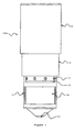
Figure 1 shows a front view of a first preferred embodiment of the invention, depicting a telescopic cylindrical covering and mounting structure in pendant arrangement, with electronic adjustment controls, LEDs, a second PIR motion detector lens and a first motion detector lens, in a fully extended position. -
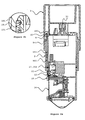
Figure 2a shows a cross-section view of the embodiment as shown inFigure 1 . -
Figure 2b shows an enlarged view of the area marked "A" inFigure 2a . -
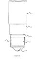
Figure 3 shows a front view of the embodiment as shown inFigure 1 , with the LEDs and the second PIR motion detector lens fully visible. -
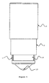
Figure 4 shows a front view of the embodiment as shown inFigure 1 , with the second PIR motion detector lens fully visible. -
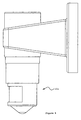
Figure 5 shows a front view of the embodiment as shown inFigure 1 , with the second PIR motion detector lens partly visible. -
Figure 6 shows a cross-section view of the embodiment as shown inFigure 5 . -
Figure 7 shows a front view of the embodiment as shown inFigure 1 , with the electronic adjustment controls, the LEDs and the second PIR motion detector lens in a concealed position. -
Figure 8 shows a side view of the first embodiment shown inFigure 1 being wall-mounted in a pendant arrangement. -
Figure 9 shows a side view of the first embodiment shown inFigure 1 being ceiling-mounted in a pendant arrangement. -
Figure 10a shows a front view of a second preferred embodiment of the invention, depicting a single body cylindrical covering and mounting structure in pendant arrangement, with electronic adjustment controls, LEDs, and second PIR motion detector lens being selectively masked by an exterior covering structure. -
Figure 10b shows a top view of the embodiment shown inFigure 10a . -
Figure 11 shows a perspective view of the embodiment shown inFigure 10a . -
Figure 12 shows a front view of a third preferred embodiment of the invention, depicting a telescopic cylindrical covering and mounting structure in standing post arrangement, with electronic adjustment controls, LEDs and second PIR motion detector lens in a fully extended position. - For clarity, alphabets "a", "b" and "c" are used to differentiate the three embodiments. For the sake of explanation, a first embodiment of the invention is elaborated in the form of a cylindrical telescopic covering and mounting structure (10a) disposed in a pendant arrangement. The covering and mounting structure (10a) is either wall-mounted or ceiling-mounted as shown in
Figures 8 and9 , respectively. - Referring first to
Figures 1 and2a , a cylindrical telescopic covering and mounting structure (10a) is shown in its fully extended position. Electronic adjustment controls (11), LEDs (12), a second PIR motion detector lens (14) and a first motion detector lens (13) are carried on the covering and mounting structure (10a). The first motion detector lens (13) is downwardly viewing and provides a limited motion detection. The second PIR motion detector lens (14) is laterally viewing and provides wider motion detection. - The covering and mounting structure (10a) comprises an inner tube (1), an intermediate tube (2) and an outer tube (3), and the three tubes (1, 2, 3) are telescopically assembled. The inner tube (1) carries the downwardly viewing first motion detector lens (13), and the laterally viewing second PIR motion detector lens (14) above the first motion detector lens (13). The inner tube (1) also carries the LEDs (12) and the electronic adjustment controls (11), with the electronic adjustment controls (11) placed above the LEDs (12). The outer tube (3) and said intermediate tube (2) serve to receive said inner tube (1).
- A sensor bottom cover (15), to which the electronic adjustment controls (11), the LEDs (12) and the second PIR motion detector lens (14) are bodily connected, is allowed to move up and down, but limited by the position of the intermediate tube (2) and the outer tube (3). The tubes (2, 3) are attached together, with the assistance of mechanical means such as clips, to create an enclosure in which the inner tube (1) is able to move. These tubes (2. 3) are also the interface tubes, whereby these designs are adapted to provide the mechanical interface with the device to which the sensor is being applied.
- Now referring to
Figures 2a, 2b and6 , a sensor top cover (18) is jammed or secured with a suitable mechanical means between the intermediate and inner tubes (2, 1). A horizontal protrusion (181) is provided around the internal circumference of the sensor top cover (18). A plurality of grooves (151) is provided throughout the length of the inner tube (1) at pre-determined interval on its external circumference. The horizontal protrusion (181) engages appropriate groove (151) on the up and down movement of the inner tube (1) at each adjustment position. - An O-ring (17), disposed in a pre-determined groove (152) on the sensor bottom cover (15), provides sufficient interface with intermediate tube (2), in order to achieve the necessary seal against water ingression.
- In addition to the upward or downward adjustment, a side to side or pan adjustment is also provided by an axial rotation created between the outer tube (3) and the sensor top cover (18). This is being achieved by means of a vertical protrusion (31) inside the outer tube (3) and an interfacing boss on the sensor top cover (18).
- The electronic adjustment controls (11), the LEDs (12) and the laterally viewing second PIR motion detector lens (14) are progressively and selectively concealed by adjacent tube (2, 3), when retracting the inner tube (1) into the intermediate and outer tubes (2, 3).
- As shown in
Figure 3 , the inner tube (1) is partially retracted. The LEDs (12), the full second PIR motion detector lens (14), and the downwardly viewing first motion detector lens (13) are visible. As shown inFigure 4 , the inner tube (1) is further retracted. The full second PIR motion detector lens (14) and the first motion detector lens (13) are visible. As shown inFigures 5 and6 , the inner tube (1) is further retracted. Only part of the second PIR motion detector lens (14) and the full first motion detector lens (13) are visible. As shown inFigure 7 , the inner tube (1) is completely retracted. The electronic adjustment controls (11), the LEDs (12) and the second PIR motion detector lens (14) are now concealed. Only the first motion detector lens (13) is visible. - The covering and mounting structure (10a) can be mounted on a wall or on a ceiling. A wall-mounted and a ceiling-mounted covering and mounting structure (10a) are as shown in
Figures 8 and9 , respectively. - The intention of the present invention is not restricted to the first embodiment illustrated and described above. Other embodiments, modifications and alterations can be made within the scope of the invention defined in the appended claims.
- A second embodiment is a single body cylindrical covering and mounting structure (10b), as shown in
Figures 10a, 10b and11 . Since the covering and mounting structure (10b) is not telescopic, an exterior covering structure (4) is therefore employed to mask selectively the product features carried thereon. It is important to note that the shape of the exterior covering structure (4) must match and fit the shape of the mounting structure. Again, the second preferred embodiment can be disposed in a pendant or standing post arrangement. In the case of pendant arrangement, it is advantageous to include a downwardly viewing first motion detector lens (13) and a laterally viewing second PIR motion detector lens (14) for motion detection, according to the teaching of the invention. In the case of standing post arrangement, only a laterally viewing second PIR motion detector lens (14) is employed. - A third preferred embodiment of the invention depicts a telescopic cylindrical covering and mounting structure (10c) disposed in a standing post arrangement, with electronic adjustment controls (11), LEDs (12) and second PIR motion detector lens (14), in a fully extended position, as shown in
Figure 12 . It is important to note that only one laterally viewing second PIR motion detector lens (14) is provided on the covering and mounting structure. - In the three embodiments mentioned above, the covering and mounting structures (10a, 10b, 10c) are all cylindrical in shape. It is obvious to those skilled in the arts that the covering and mounting structure (10) can be constructed in a non-cylindrical shape. In that situation, non-circular channel is employed instead of tube in the telescopic design.
- The following paragraphs describe preferred aspects of the invention:
- A) A covering and mounting structure (10a) for electronic adjustment controls (11), light emitting diodes (LEDs) (12), at least one motion detector lens (14, 13) all for use in a motion detector device, characterized in that the covering and mounting structure comprises an inner tube (1) or channel, an intermediate tube (2) or channel and an outer tube (3) or channel, all three tubes (1, 2, 3) being telescopically assembled, such that the covering and mounting structure selectively masks the electronic adjustment controls (11), the LEDs (12) and the at least one motion detector lens (14, 13).
- B) A telescopic covering and mounting structure (10a) as in paragraph A in which the covering and mounting structure (10a) is disposed in a pendant arrangement, whereas the inner tube (1) or channel carries a downwardly viewing first motion detector lens (13), and a laterally viewing second passive infra-red (PIR) motion detector lens (14) above the first motion detector lens (13); the inner tube (1) or channel also carries the LEDs (12) and the electronic adjustment controls (11) which are placed above the LEDs (12); and the outer tube (3) or channel serving to receive said intermediate and inner tubes (2, 1) or channels.
- C) A telescopic covering and mounting structure (10a) as in paragraphs A or B in which the body of the mounting structure is always able to hang vertically down, whether ceiling-mounted or wall-mounted.
- D) A telescopic covering and mounting structure (10a) as in paragraphs A or B in which the electronic adjustment controls (11), the LEDs (12) and the laterally viewing second PIR motion detector lens (14) are progressively and selectively concealed by adjacent tube or channel, when retracting the inner tube (1) or channel into the intermediate and outer tubes (2, 3) or channels.
- E) A telescopic covering and mounting structure (10c) as in paragraph A in which the covering and mounting structure (10c) is disposed in a standing post arrangement, whereas the inner tube (1) or channel carries a laterally viewing second PIR motion detector lens (14), LEDs (12) and electronic adjustment controls (11).
- F) A telescopic covering and mounting structure (10a, 10c) as in paragraph A in which the covering and mounting structure (10a, 10c) is cylindrical in shape.
- G) A telescopic covering and mounting structure (10a, 10c) as in paragraph A in which the covering and mounting structure (10a, 10c) is non-cylindrical in shape.
- H) A non-telescopic covering and mounting structure (10b) for electronic adjustment controls (11), LEDs (12), at least one motion detector lens (14, 13), all for use in a motion detector device, characterized in that the covering and mounting structure is a single body design, carrying at least one motion detector lens (14, 13), LEDs (12) and electronic adjustment controls (11); whereas
an exterior covering structure (4) is employed to mask selectively the electronic adjustment controls (11), the LEDs (12), and the motion detector lens (14). - I) A non-telescopic covering and mounting structure (10b) for use in a motion detector device as in paragraph H in which the shape of the exterior covering structure (4) must match and fit the shape of the mounting structure.
- J) A non-telescopic covering and mounting structure (10b) for use in a motion detector device as in paragraph H in which the mounting structure is disposed in a pendant arrangement, and the mounting structure carries a downwardly viewing first motion detector lens (13) and a laterally viewing second PIR motion detector lens (14).
- K) A non-telescopic covering and mounting structure (10b) for use in a motion detector device as in paragraph H in which the mounting structure is disposed in a standing post arrangement, whereas the mounting structure carries a laterally viewing second PIR motion detector lens (14).
- L) A non-telescopic covering and mounting structure (10b) for use in a motion detector device as in paragraph H in which the mounting structure is cylindrical in shape.
- M) A non-telescopic covering and mounting structure (10b) for use in a motion detector device as in paragraph H in which the mounting structure is non-cylindrical in shape.
Claims (6)
- A non-telescopic covering and mounting structure (10b) for electronic adjustment controls (11), LEDs (12), at least one motion detector lens (14, 13), all for use in a motion detector device, characterized in that the covering and mounting structure is a single body design, carrying at least one motion detector lens (14, 13), LEDs (12) and electronic adjustment controls (11); whereas
an exterior covering structure (4) is employed to mask selectively the electronic adjustment controls (11), the LEDs (12), and the motion detector lens (14). - A non-telescopic covering and mounting structure (10b) for use in a motion detector device as in Claim 1 in which the shape of the exterior covering structure (4) must match and fit the shape of the mounting structure.
- A non-telescopic covering and mounting structure (10b) for use in a motion detector device as in Claim 1 in which the mounting structure is disposed in a pendant arrangement, and the mounting structure carries a downwardly viewing first motion detector lens (13) and a laterally viewing second PIR motion detector lens (14).
- A non-telescopic covering and mounting structure (10b) for use in a motion detector device as in Claim 1 in which the mounting structure is disposed in a standing post arrangement, whereas the mounting structure carries a laterally viewing second PIR motion detector lens (14).
- A non-telescopic covering and mounting structure (10b) for use in a motion detector device as in Claim 1 in which the mounting structure is cylindrical in shape.
- A non-telescopic covering and mounting structure (10b) for use in a motion detector device as in Claim 1 in which the mounting structure is non-cylindrical in shape.
Applications Claiming Priority (1)
| Application Number | Priority Date | Filing Date | Title |
|---|---|---|---|
| EP02253625A EP1365370B1 (en) | 2002-05-23 | 2002-05-23 | A covering and mounting means for motion detector |
Related Parent Applications (1)
| Application Number | Title | Priority Date | Filing Date |
|---|---|---|---|
| EP02253625A Division EP1365370B1 (en) | 2002-05-23 | 2002-05-23 | A covering and mounting means for motion detector |
Publications (1)
| Publication Number | Publication Date |
|---|---|
| EP2043065A1 true EP2043065A1 (en) | 2009-04-01 |
Family
ID=29286222
Family Applications (2)
| Application Number | Title | Priority Date | Filing Date |
|---|---|---|---|
| EP02253625A Expired - Lifetime EP1365370B1 (en) | 2002-05-23 | 2002-05-23 | A covering and mounting means for motion detector |
| EP08019589A Withdrawn EP2043065A1 (en) | 2002-05-23 | 2002-05-23 | A covering and mounting structure for motion detector, light emitting diodes and electronic adjustment controls |
Family Applications Before (1)
| Application Number | Title | Priority Date | Filing Date |
|---|---|---|---|
| EP02253625A Expired - Lifetime EP1365370B1 (en) | 2002-05-23 | 2002-05-23 | A covering and mounting means for motion detector |
Country Status (3)
| Country | Link |
|---|---|
| EP (2) | EP1365370B1 (en) |
| AT (1) | ATE424014T1 (en) |
| DE (1) | DE60231289D1 (en) |
Cited By (1)
| Publication number | Priority date | Publication date | Assignee | Title |
|---|---|---|---|---|
| EP2312545A1 (en) | 2009-10-15 | 2011-04-20 | HAGER CONTROLS (Société par Actions Simplifiée) | Motion detector with mobile cover |
Families Citing this family (6)
| Publication number | Priority date | Publication date | Assignee | Title |
|---|---|---|---|---|
| FR2934377B1 (en) * | 2008-07-28 | 2010-10-29 | Hager Controls | PASS DETECTOR WITH DETECTION AREAS THAT CAN BE PREDEFINED |
| AU2011100726B4 (en) * | 2011-06-09 | 2012-01-19 | Gerard Lighting Pty Ltd | PIR sensor with retractable controls |
| US11333334B2 (en) | 2018-01-29 | 2022-05-17 | Heathco Llc | Rotatable light fixture secured to a junction box via a base |
| US11346514B2 (en) | 2020-09-14 | 2022-05-31 | Heathco Llc | Rotationally adjustable outdoor security light |
| US11280458B1 (en) | 2020-09-14 | 2022-03-22 | Heathco Llc | Mechanical and electrical interface for security light mounting |
| US11231152B1 (en) | 2020-09-14 | 2022-01-25 | Heathco Llc | Variable power supply security light |
Citations (8)
| Publication number | Priority date | Publication date | Assignee | Title |
|---|---|---|---|---|
| US4873469A (en) * | 1987-05-21 | 1989-10-10 | Pittway Corporation | Infrared actuated control switch assembly |
| DE4006631A1 (en) * | 1990-03-03 | 1991-09-05 | Berker Geb | Protective cover for IR motion detector - has segmented hood enabling continuous range of adjustment by varying detection angles |
| EP0542170A2 (en) | 1991-11-15 | 1993-05-19 | ABBPATENT GmbH | Passive infra-red movement detector |
| DE9406661U1 (en) * | 1994-04-21 | 1994-06-30 | Merten Gmbh & Co Kg Geb | Mask for an infrared motion detector |
| US5440292A (en) * | 1994-06-20 | 1995-08-08 | Guard-Tech Industries, Inc. | Intrusion detector |
| EP0772168A2 (en) * | 1995-11-01 | 1997-05-07 | Thomson Consumer Electronics, Inc. | Infrared surveillance system with controlled video recording |
| US5739753A (en) | 1996-09-19 | 1998-04-14 | Leviton Manufacturing Co., Inc. | Detector system with adjustable field of view |
| USD424727S (en) | 1996-10-07 | 2000-05-09 | Steinel Gmbh & Co. K.G. | Combined motion detector and security lights |
Family Cites Families (2)
| Publication number | Priority date | Publication date | Assignee | Title |
|---|---|---|---|---|
| US4703171A (en) * | 1985-11-05 | 1987-10-27 | Target Concepts Inc. | Lighting control system with infrared occupancy detector |
| DE29503531U1 (en) * | 1995-03-03 | 1995-05-18 | Rev Ritter Gmbh | Motion detector with infrared sensor |
-
2002
- 2002-05-23 AT AT02253625T patent/ATE424014T1/en not_active IP Right Cessation
- 2002-05-23 DE DE60231289T patent/DE60231289D1/en not_active Expired - Fee Related
- 2002-05-23 EP EP02253625A patent/EP1365370B1/en not_active Expired - Lifetime
- 2002-05-23 EP EP08019589A patent/EP2043065A1/en not_active Withdrawn
Patent Citations (8)
| Publication number | Priority date | Publication date | Assignee | Title |
|---|---|---|---|---|
| US4873469A (en) * | 1987-05-21 | 1989-10-10 | Pittway Corporation | Infrared actuated control switch assembly |
| DE4006631A1 (en) * | 1990-03-03 | 1991-09-05 | Berker Geb | Protective cover for IR motion detector - has segmented hood enabling continuous range of adjustment by varying detection angles |
| EP0542170A2 (en) | 1991-11-15 | 1993-05-19 | ABBPATENT GmbH | Passive infra-red movement detector |
| DE9406661U1 (en) * | 1994-04-21 | 1994-06-30 | Merten Gmbh & Co Kg Geb | Mask for an infrared motion detector |
| US5440292A (en) * | 1994-06-20 | 1995-08-08 | Guard-Tech Industries, Inc. | Intrusion detector |
| EP0772168A2 (en) * | 1995-11-01 | 1997-05-07 | Thomson Consumer Electronics, Inc. | Infrared surveillance system with controlled video recording |
| US5739753A (en) | 1996-09-19 | 1998-04-14 | Leviton Manufacturing Co., Inc. | Detector system with adjustable field of view |
| USD424727S (en) | 1996-10-07 | 2000-05-09 | Steinel Gmbh & Co. K.G. | Combined motion detector and security lights |
Cited By (1)
| Publication number | Priority date | Publication date | Assignee | Title |
|---|---|---|---|---|
| EP2312545A1 (en) | 2009-10-15 | 2011-04-20 | HAGER CONTROLS (Société par Actions Simplifiée) | Motion detector with mobile cover |
Also Published As
| Publication number | Publication date |
|---|---|
| EP1365370A1 (en) | 2003-11-26 |
| EP1365370B1 (en) | 2009-02-25 |
| DE60231289D1 (en) | 2009-04-09 |
| ATE424014T1 (en) | 2009-03-15 |
Similar Documents
| Publication | Publication Date | Title |
|---|---|---|
| US6844555B2 (en) | Covering and mounting structure for a motion detector having light emitting diodes and electronic adjustment controls | |
| JP6465951B2 (en) | Camera structure with illuminator | |
| US6348691B1 (en) | Motion detector with extra-wide angle mirrored optics | |
| US8337100B2 (en) | Dome security camera | |
| US20070177384A1 (en) | Motion sensing lighting fixture | |
| US7543958B2 (en) | Lighting fixture with a retractable sensor module and methods of operating the same | |
| US5649761A (en) | Motion detector with side-pivoting light fixture | |
| US5282118A (en) | Lighting fixture with integral motion detector | |
| US6346705B1 (en) | Hidden PIR motion detector with mirrored optics | |
| RU2606384C2 (en) | Integral troffer motion detector | |
| US5434764A (en) | Lighting fixture with integral motion detector | |
| US20140204347A1 (en) | Message Projection System | |
| EP2533026A2 (en) | Coaxial PIR and light sensor | |
| EP3642813B1 (en) | A sensor assembly and a device comprising such sensor assembly | |
| EP1365370B1 (en) | A covering and mounting means for motion detector | |
| JP2007328114A (en) | Light emitting element display structure of outdoor device | |
| KR200422158Y1 (en) | Easily lens control guard camera | |
| JPH08321215A (en) | Illumination fixture | |
| KR200482975Y1 (en) | Lighting equipment | |
| KR101369894B1 (en) | Sensor light capable of adjusting sensing angle | |
| KR101899494B1 (en) | A camera device having a magnet fastening structure capable of adjusting a monitoring position from the outside | |
| KR200455107Y1 (en) | Dome Camera with Illumination | |
| KR101441611B1 (en) | Sensor light capable of adjusting sensing angle | |
| KR200380960Y1 (en) | Camera module fixing holder for cctv | |
| KR101032985B1 (en) | Camera for Closed Circuit Television capable of Focusing and Zooming In/Out |
Legal Events
| Date | Code | Title | Description |
|---|---|---|---|
| PUAI | Public reference made under article 153(3) epc to a published international application that has entered the european phase |
Free format text: ORIGINAL CODE: 0009012 |
|
| 17P | Request for examination filed |
Effective date: 20081127 |
|
| AC | Divisional application: reference to earlier application |
Ref document number: 1365370 Country of ref document: EP Kind code of ref document: P |
|
| AK | Designated contracting states |
Kind code of ref document: A1 Designated state(s): AT BE CH CY DE DK ES FI FR GB GR IE IT LI LU MC NL PT SE TR |
|
| STAA | Information on the status of an ep patent application or granted ep patent |
Free format text: STATUS: THE APPLICATION HAS BEEN WITHDRAWN |
|
| 18W | Application withdrawn |
Effective date: 20090611 |