EP2042957A2 - Method for automatic time synchronisation of devices in network-based systems - Google Patents
Method for automatic time synchronisation of devices in network-based systems Download PDFInfo
- Publication number
- EP2042957A2 EP2042957A2 EP08164067A EP08164067A EP2042957A2 EP 2042957 A2 EP2042957 A2 EP 2042957A2 EP 08164067 A EP08164067 A EP 08164067A EP 08164067 A EP08164067 A EP 08164067A EP 2042957 A2 EP2042957 A2 EP 2042957A2
- Authority
- EP
- European Patent Office
- Prior art keywords
- server
- field device
- time
- data
- current time
- Prior art date
- Legal status (The legal status is an assumption and is not a legal conclusion. Google has not performed a legal analysis and makes no representation as to the accuracy of the status listed.)
- Granted
Links
- 238000000034 method Methods 0.000 title claims abstract description 75
- 238000004590 computer program Methods 0.000 claims abstract description 13
- 238000004891 communication Methods 0.000 claims description 50
- 230000008569 process Effects 0.000 claims description 19
- 230000004044 response Effects 0.000 claims description 14
- 238000012937 correction Methods 0.000 claims description 10
- 230000005540 biological transmission Effects 0.000 claims description 9
- 238000012546 transfer Methods 0.000 claims description 8
- 230000008859 change Effects 0.000 claims description 2
- 230000003750 conditioning effect Effects 0.000 description 39
- 230000001360 synchronised effect Effects 0.000 description 7
- 238000012545 processing Methods 0.000 description 6
- 238000006243 chemical reaction Methods 0.000 description 5
- 238000011156 evaluation Methods 0.000 description 5
- 238000004801 process automation Methods 0.000 description 4
- 230000001960 triggered effect Effects 0.000 description 4
- 238000012790 confirmation Methods 0.000 description 3
- 230000006870 function Effects 0.000 description 3
- 238000005259 measurement Methods 0.000 description 3
- 238000012800 visualization Methods 0.000 description 3
- 230000004913 activation Effects 0.000 description 2
- 230000000977 initiatory effect Effects 0.000 description 2
- 230000003993 interaction Effects 0.000 description 2
- 230000009471 action Effects 0.000 description 1
- 239000004020 conductor Substances 0.000 description 1
- 230000001419 dependent effect Effects 0.000 description 1
- 238000001514 detection method Methods 0.000 description 1
- 230000009977 dual effect Effects 0.000 description 1
- 239000003999 initiator Substances 0.000 description 1
- 230000007246 mechanism Effects 0.000 description 1
- 230000002123 temporal effect Effects 0.000 description 1
Images


Classifications
-
- G—PHYSICS
- G05—CONTROLLING; REGULATING
- G05B—CONTROL OR REGULATING SYSTEMS IN GENERAL; FUNCTIONAL ELEMENTS OF SUCH SYSTEMS; MONITORING OR TESTING ARRANGEMENTS FOR SUCH SYSTEMS OR ELEMENTS
- G05B19/00—Programme-control systems
- G05B19/02—Programme-control systems electric
- G05B19/04—Programme control other than numerical control, i.e. in sequence controllers or logic controllers
- G05B19/042—Programme control other than numerical control, i.e. in sequence controllers or logic controllers using digital processors
-
- G—PHYSICS
- G06—COMPUTING; CALCULATING OR COUNTING
- G06F—ELECTRIC DIGITAL DATA PROCESSING
- G06F1/00—Details not covered by groups G06F3/00 - G06F13/00 and G06F21/00
- G06F1/04—Generating or distributing clock signals or signals derived directly therefrom
- G06F1/14—Time supervision arrangements, e.g. real time clock
-
- G—PHYSICS
- G05—CONTROLLING; REGULATING
- G05B—CONTROL OR REGULATING SYSTEMS IN GENERAL; FUNCTIONAL ELEMENTS OF SUCH SYSTEMS; MONITORING OR TESTING ARRANGEMENTS FOR SUCH SYSTEMS OR ELEMENTS
- G05B2219/00—Program-control systems
- G05B2219/20—Pc systems
- G05B2219/25—Pc structure of the system
- G05B2219/25478—Synchronize several controllers using syncline
-
- G—PHYSICS
- G05—CONTROLLING; REGULATING
- G05B—CONTROL OR REGULATING SYSTEMS IN GENERAL; FUNCTIONAL ELEMENTS OF SUCH SYSTEMS; MONITORING OR TESTING ARRANGEMENTS FOR SUCH SYSTEMS OR ELEMENTS
- G05B2219/00—Program-control systems
- G05B2219/20—Pc systems
- G05B2219/25—Pc structure of the system
- G05B2219/25479—Synchronize controllers using messages, add transmission time afterwards
-
- H—ELECTRICITY
- H04—ELECTRIC COMMUNICATION TECHNIQUE
- H04J—MULTIPLEX COMMUNICATION
- H04J3/00—Time-division multiplex systems
- H04J3/02—Details
- H04J3/06—Synchronising arrangements
- H04J3/0635—Clock or time synchronisation in a network
- H04J3/0638—Clock or time synchronisation among nodes; Internode synchronisation
- H04J3/0658—Clock or time synchronisation among packet nodes
- H04J3/0661—Clock or time synchronisation among packet nodes using timestamps
- H04J3/0667—Bidirectional timestamps, e.g. NTP or PTP for compensation of clock drift and for compensation of propagation delays
Definitions
- the present invention relates to a method for automatic time synchronization of field devices in network-based systems, a network-based measuring system for automatic time synchronization, a computer program for automatic time synchronization of field devices, a storage medium on which a computer program for automatic time synchronization of field devices is stored and a microprocessor with such computer program.
- a uniform time base is essential. If these are device / server systems with servers that are to receive and archive measured value and device information with time stamp information from their devices, then this uniform time base is urgently required. In particular, when the devices or clients to collect information such as measured value information over a long period of time and to block at a suitable time to the server.
- time server is cyclically contacted for the automated synchronization of a globally uniform time base of computers that have access to the Internet.
- a time server is usually synchronized by a high-precision clock or by several other time servers.
- Every computer that wants to use this service should be specially set up to use a time server. This is done manually on site for each individual device and can mean a significant amount of work with a significant potential for sources of error in terms of a uniform time base in a worldwide distribution of equipment. However, if you would like to use this option for controllers or field devices in the field of process automation, then you have to realize that the commissioning staff is often overwhelmed with these necessary settings and systems because it does not have the necessary know-how. Likewise, this procedure is complex and it is not ensured that an incorrect operation takes place during operation, as a result of which the time base is changed or the set time server can no longer be reached.
- the terms client, measuring device or signal conditioning instrument will be used synonymously for the term field device, wherein all embodiments of the present invention may always refer to a plurality of field devices and field device controllers.
- the present invention is possible for any technical device that can acquire data and has a clock.
- a method based on a communication and data network for the automatic time synchronization of field devices namely level gauges, pressure gauges and field device controls is given.
- a current time value by the field device or the Field device control determines, and it is provided by, in a or to a central server, a target value.
- the current time value is set to the setpoint value if the setpoint deviates from the current time value by more than a predetermined threshold value.
- the process of determining a current time value corresponds to the generation of so-called time comparison data by at least one field device.
- the method according to the invention thus makes it possible to automatically ensure that there is a uniform time base in the server and the field device in adjustable regularity, which can be predefined by the user, for example. Since the field devices are factory-set or server-side centrally to their respective time zone and the server knows in which time zone the device is located, centrally data that is time-critical (data in which the acquisition time plays an important role) can be accessed worldwide distributed field devices are compared and combined as needed. It can be ensured by the server that a correct conversion of the current time of day of a field device is performed on the factory or Serverzeitzone.
- the inventive method is based on a data and communication network or the server, the field devices and the Field device controllers are integrated in this network.
- data and communication networks are, for example, network-based, Internet-based, web-based, network-based, or based on a browser-based network.
- the method can also provide server-side control and correction of the time zones in the respective field device or in the respective controller. This dual control by the server over the globally distributed external devices ensures compliance with the synchronicity of all participating external devices to each other and to the server with respect to respective time zones.
- This method may also involve asking the field device from the server for a clock comparison by means of the communication connection.
- the following description of the figures describes a process chain which is triggered by such a request of the server.
- a transmission of the time information is prescribed and guaranteed by the method according to an embodiment of the present invention.
- the exemplary embodiments of the method presented below can be executed by the measuring system according to the invention, the computer program and the microprocessor, or stored on the storage medium.
- the method comprises the step of transferring data from the field device or the field device control by the server into a database. In this case, this step is performed only if the setpoint deviates from the current time value by at most the predetermined threshold value.
- the method according to the invention thus ensures that acquisition of data of the field device by the server is possible only after securing identical times and a same time base in the server and the field device. If any combinations of the data stored on the server are then used for visualization or further processing, the user can be sure that data that has been transmitted to and stored by the server from various locations worldwide is compared with the desired accuracy in terms of time can. Thus, the transfer of stored data by the server to higher-level processing instances or processing tools with respect to the time information that belongs to the respective data is not critical.
- the server thus serves for the central distribution of time information to the field devices and the field device controls and is thus available to a hitherto manually performed time management of field devices at the respective device location as an advantageous alternative.
- the data can be in any file format, for example in an XML file format. It also ensures the data and communication network data transfer, including the transfer of individual files and the block-by-file transmission of the files for synchronization.
- the method provides for sending the current time value by the field device to the server and determining the time difference between the current time value and the setpoint.
- the field devices thus provide time information, which may be present in the XML structure ⁇ Device>, for example, in order to deliver the current time in the signal conditioning instrument, ie at the time of the data exchange, with the server.
- the current time value or this time information or this time comparison data can be created and transmitted in any file format, as long as the comparison on the server with the desired value can be made.
- These time comparison data contain, in addition to the device name, the device type, the version, the serial number, the IP address of the device also the essential current time of the field device at the location of the field device and date.
- This time comparison data or the XML element "Device” can be sent in certain cases for the purpose of pure time alignment, even without the measured value information. This then serves only to ensure a synchronicity between server and field device.
- the server additionally sends a response to the field device that the system time of the field device is in order if the desired value deviates from the current time value by at most the predetermined threshold value.
- all data to be stored are transmitted from the field device to the server and the server confirms the data reception in a further step.
- This method therefore ensures that data that has been transmitted from the field device to the server via the communication network can only be stored on the server if the time of the field device has been automatically and immediately adapted to the time of the server. So only if there is synchrony and an equal time base between all field devices and the server, data can be stored on the server side. Both a block-wise transmission of data and a single, sequential transmission of data through the data and communication network is possible. In this case, the transmission can be realized by an http protocol, from which an acknowledgment or confirmation upon data reception by the server with an http status 200 is answered.
- the synchronization or the initiation of this synchronization can be initiated both automatically by the server or the field device or the field device control, however, is an instantaneous request of the user to start the process anytime possible. This represents an additional and alternative safety measure within the method according to the invention.
- the method further comprises sending a server time to the field device and prompting for a time slot Synchronization of the field device with the server. Similarly, storing the "time synchronization in the field device" operation in a message buffer on the server is part of this embodiment.
- the server sends its time to the field device.
- an error has been corrected on the part of the signal conditioning instrument or field device with regard to the current time or with regard to the setting of the time zone. This is registered by storing this process in a message buffer on the server, ie a specially designed database.
- the method according to the invention is implemented in the detection system WEB-VV.
- the method according to the invention can be implemented and used, for example, in the web-based measured value acquisition and visualization system WEB-VV.
- WEB-VV which system now serves as a server, receives its measured value information with associated time stamps from a multiplicity of signal conditioning instruments as (for example XML) files and stores them centrally in a database which is designed for this purpose.
- the stored data can be combined as desired in the WEB-VV server and visualized via browser access as so-called measured value views or for further processing to higher-level tools, eg. B. logistics tools are served.
- the goal of keeping the time base synchronized for all devices involved in the WEB-VV network is most easily achieved by having all devices receive the time information centrally from one point.
- the method according to the invention includes the step of requesting the field device by the server for a clock comparison.
- the server sends a command to the desired field device with the goal of the clock comparison.
- the signal conditioning instrument generates an XML file, but in any case a time comparison file, and delivers it to the server. For example, back to WEB-VV, where the deviation between device time and server time is checked.
- the method according to the invention furthermore provides for the server to only be able to accept the data if it has been ensured that identical times prevail in the server and the respective data-supplying field device or if the difference from the setpoint value (FIG. am) server and device time (ie the current time value, ie on the field device or the field device control) does not exceed the threshold.
- the server to only be able to accept the data if it has been ensured that identical times prevail in the server and the respective data-supplying field device or if the difference from the setpoint value (FIG. am) server and device time (ie the current time value, ie on the field device or the field device control) does not exceed the threshold.
- a server is to be understood as a time server which is able to provide a time reference to a connected field device via a network.
- At least one of the data groups "time comparison data” and “data to be stored” in an XML file format is used in the method according to the invention.
- Extensible Markup Language is a markup language for representing hierarchically structured data in the form of text files. Since these data are particularly suitable for the exchange between different IT systems on the Internet, it may be advantageous to use this file format in the method according to the invention.
- all field devices in the method according to the invention receive the time information centrally by the server.
- This server-side control and provision of time in the field devices provides the highest level of security to guard against manual operator errors in the field devices distributed worldwide, incorrect settings of the time zone offset within the operating software of the field devices, and against the technically given time drift of the clocks within the field devices.
- Checking the correct timing of each field device is performed at a sufficiently high rate (it does not matter if this was initiated on the server side or on the field device side). In this way it can be achieved that the time for all participating field devices is automatically kept synchronous by the server. This is done not least by controlling and possibly correcting the time zones set in each field device or in the operating software of the respective field device by the server.
- an http communication between the server and the field devices is used in the method according to the invention.
- http hypertext transfer protocol
- the method according to the invention uses the Internet as the communication and data network.
- setting the current time value comprises both the time synchronization of the field device with Correcting a real-time clock of the field device and correcting time stamps for the currently produced data in the field device.
- this procedure ensures that the files are also the correct one Contain time information that is being produced during a synchronization. All data of such a file, from the first to the last, thus contain the same and correct time information adapted to the server time after a synchronization.
- the method according to the invention furthermore has the step of collecting different data records with associated time stamps in the field device and the step of changing all time stamps for a pending time synchronization.
- trend data or history data can also be stored.
- data is collected over a longer period of time than a typical average measurement or a typical average recording of data and made available in blocks later.
- these so-called trend data to also be completely provided with a correct time stamp, not only the device time of the field device, but also the trend data and its time stamp are synchronized and thus activated in the event of synchronization adjusted the server time.
- the field device makes contact with the server at predefined times via the communication and data network.
- This embodiment allows for a sufficiently accurate timing or setting the predefined times the synchrony between server and field device to a minimum residual risk. It is alternatively or additionally possible that a current request for time synchronization can be triggered by the user.
- a data and communication network-based measuring system for measuring a fill level or a pressure and for automatic time synchronization.
- the measuring system has a server, at least one field device or at least one field device control and a communication connection between the server and the at least one field device or the at least one field device control for mutual data transmission.
- the field device or the field device control is designed to determine a current time value
- the server is set up to provide a setpoint value.
- the server is set to set the current time value to the setpoint if the setpoint deviates from the current time value by more than a predetermined threshold.
- an indispensable uniform time base can thus be ensured on both sides of the system in worldwide network-based client / server systems in which the server is to receive and archive measured value and device information with time stamp information.
- the clients that is to say the field devices
- this time control or time correction by the server is of absolute importance.
- the configuration of the time zones and the provision of the reference time, namely the server time of the field devices involved takes place at a central point, namely only at the named server.
- Both a natural technical time drift and an inadvertently changed value in the time base of the field device on site is registered by the server and the next time the communication with the field device, the time base is automatically set back to the setpoint, namely the system time of the server or set the correct time zone.
- the measuring system according to the invention is equipped with a field device which is set up in such a way as to generate time comparison data and to send time comparison data to the server.
- the server is set up to provide a threshold for the allowed time deviation and is able to determine the time difference between the current one Time value and the setpoint to determine.
- the server may compare the time difference with the threshold and decide whether the time difference is greater or less than the threshold.
- the server is set up so that it can send a response to the field device in which the field device is informed that the time of the field device is in order.
- the field device is set up for a time synchronization, whereby corrections are made to the time stamps of currently produced data in the field device.
- the field device is set up such that the data to be completely stored can be transmitted to the server.
- the server in turn is set up to take over the data in a database and can confirm the data reception via the communication and data network to the field device.
- the server is set up to send a server time to the field device and to request a time synchronization of the field device with the server.
- the server has a so-called message buffer in which the server stores the process "time synchronization in the field device".
- a computer program for automatic time synchronization of field devices namely level gauges and pressure gauges and field device controls in a communication and data network
- the computer program when executed by a processor, causing the processor to perform the following steps: determining a current time value by the field device or by the field device control and the provision of a setpoint in a central server. Furthermore, the step of comparing the current time value with the target value is executed, followed by the step of setting the current time value to the target value, if the target value deviates from the current time value by more than a predetermined threshold value.
- a storage medium is specified on which a computer program for automatic time synchronization of field devices, namely level gauges and pressure gauges as well as field device controls, is stored in a communication and data network.
- this computer program when executed by a processor, this computer program causes the processor to perform the following steps: determining a current time value by the field device or by the field device control, and providing a setpoint in a central server. Furthermore, the step is done comparing the current one Time value with the setpoint, whereupon the adjustment of the current time value to the setpoint, if the setpoint deviates from the current time value by more than a predetermined threshold value.
- a microprocessor for automatically time synchronization of field devices namely level gauges and pressure gauges and field device controls in a communication and data network and for carrying out the following steps: determining a current time value by the field device or by the field device control and the provision of a Setpoint in a central server. Similarly, the step of comparing the current time value with the target value is performed and the step of setting the current time value to the target value occurs precisely when the target value deviates from the current time value by more than a predetermined threshold value.
- Fig. 1 shows a method according to an embodiment of the present invention, in which the synchronization or the connection setup for synchronization is started from the field device.
- the field device or the field device control 101 sends 104 the current time value or the time comparison data to the server 102 after a possible event 103.
- the event can occur in the entire system, for example, it may be an event in WEB-VV, a so-called WEB-VV event.
- WEB-VV event eg an automatically generated trigger event in the field device, so z.
- the time comparison data can be present, for example, in XML format.
- 110 sends the field device the complete data to the server.
- the server 102 accepts 111 the data. Then the server confirms the file reception.
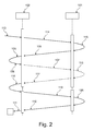
- Fig. 2 shows a schematic representation of the synchronization method according to the invention according to an embodiment of the present invention, wherein the connection structure in the embodiment shown here, starting from the server.
- the server 102 After a previous event 113 (eg, after an interaction of the WEB-VV user), the server 102 starts a clock comparison request 114 to the field device 101.
- the field device 101 responds with the current time value generation 115 current time comparison data.
- the field device 101 sends 104 the current time value or the time comparison data to the server.
- the server in turn compares 105 the current time value with the setpoint. Depending on the result of the comparison, that is, depending on whether this time difference is greater or less than a predefined threshold value, a request for time synchronization 106 takes place.
- the server 102 sends the current server time "Server Date Time” together with the "status" setDeviceTime and thus requests the field device for time synchronization.
- the field device 101 in turn reacts with a correction 116 of the device time and the trend data.
- the field device 101 sends an acknowledgment 117 to the server via the data and communication network, so far as everything is in order, e.g. For example, enter an http status 200 and confirm the correction of the device time and the trend data.
- the event "time synchronization in the field device” is stored in the message buffer in the server 102 118. This is followed by sending a request 119 for data exchange.
- the field device 101 is thus requested to generate measured value data 120, whereupon the field device 101 causes the data exchange 110 to the server 102.
- the data is sent via the data and communication network and taken over by the server 102 111.
- Fig. 3 shows a schematic measuring system according to an embodiment of the present invention, with a server 102, which contains a storage medium 130 and a CPU, so a microprocessor 131.
- the communication and data network 123 on which the method according to the invention is based is shown, and two globally distributed field devices 121 and 122 are shown by way of example. Via the communication and data network 123, it is therefore possible by the method according to the invention to realize the secure automated synchronization of the time base of these globally distributed controllers 121 and 122 in the process automation by means of a special time server 102.
- the controllers or field devices or even clients and the server can use the Internet as an exemplary embodiment of the data and communication network 123.
- Fig. 4 shows by way of example the surface of an operating software of the server for setting the device network access data for a field device of the method according to the invention. It can be clearly seen that the respective time zone in which the respective field device is located is shown here. However, it is important that the time zone is set and controlled centrally by the server according to the invention and controlled by the server. Thus, a high level of security can be ensured with respect to the synchronicity of all field devices with the server and the correct time zone setting in all external field devices. Should a user change the time zone, it will be detected by the server during the next communication over the communication and data network and will be corrected during the same communication and reset to the original correct time zone value. If such a synchronization has to take place, then this is archived in a message buffer on the server.
- Fig. 5 schematically shows an inventive measuring system 132 with a server 102 and a field device or a field device control 121. It can be clearly seen that both sides of the measuring system according to the invention the contact to the opposite side can be recorded, which is represented by the arrows starting from the respective initiator. This is done via the communication and data network 123.
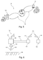
- Fig. 6 schematically shows a representation of the measuring system 132 according to the invention, which has a field device 101 and a connection 123a, for example in the form of a 4... 20 mA conductor loop for field device control 124.
- the server 102 like the field device controller and the field device, has an antenna 126.
- This antenna exemplifies the connection to the communication and data network 123.
- a wired connection may also exist.
- the field device 121 has a further second antenna 126 mounted in this image below, which in this case is aligned for measuring the fill level or the pressure.
- a transmission signal 127 and a reception signal 128 which checks the level of the contents 129.
- Fig.7 and Fig.8 show schematic representations of dialogs of the field device operating software.
- Fig. 7 represents the part in which the notification type is defined.
- Fig. 8 on the other hand, you can see the part that defines the sending time for sending messages. It can be seen that the interval of a query is displayed, which according to the invention can be set secured on the server side.
- the method according to an embodiment of the present invention forces the server owner to set the time zone for each participating client, which is central and server-side only. If the time base of a local client is accidentally changed, the server will register this on the next communication with the client and the client's time base will automatically be reset to the setpoint.
- the arrangement according to the invention can be used, for example, in the web-based measured value acquisition and visualization system "WEB-VV".
- WEB-VV web-based measured value acquisition and visualization system
- the server for example, WEB-VV receives its measured value information with associated time stamps from a variety of signal conditioning devices (clients) by file.
- this can be an XML file.
- the server also stores this information centrally in a database.
- the stored data can be combined as desired in the WEB-VV server and visualized via browser access as so-called measured value views, or passed on to higher-level tools, for example logistics tools, for further processing.
- the signal conditioning instruments can also provide history data with a timestamp as a file, for example in the form of XML data.
- FIG. 3 schematically shows a WEB-VV system.
- the server communicates with the signal conditioning instruments via four different services, whereby in the first variant the communication originates from the signal conditioning instrument.
- the service "Send measured value" is therefore initiated by the signal conditioning instrument.
- the services Scan Device Network, Update Measurement, and Set WEB VV Event Interval are initiated by the server.
- an http communication can be used, which allows both sides to obtain time information from the other party and to use it accordingly. Since the signal conditioning instruments can be located in any time zone, WEB-VV must be notified manually once when creating a device network. This is done by a prepared configuration dialog in the WEB-VV (see Fig. 4 ).
- WEB-VV is thus enabled to return its current time corrected to the local time of the signal conditioning instruments (see Fig. 5 ).
- both the signal conditioning devices and the WEB VV servers transmit their time information to the respective counterpart during each connection except for the "Scan Device Network” service.
- the decision as to whether a time synchronization should be made in the signal conditioning instrument lies solely with the server, in this case WEB-VV. This requests the signal conditioning instrument to synchronize if necessary.
- WEB-VV checks the device time information of incoming data, so for example from XML measured value data and compares this with the current computer time, ie the time of the server.
- the signal conditioning instruments store time stamp information in the structure ⁇ Values> in the measured value data, in this case in the XML measured value data.
- This time stamp information represents the time at which a measured value was recorded in the signal conditioning instrument and stored in the buffer.
- the signal conditioning instruments provide time information in the structure ⁇ Device>. This time information provides the current time in the signal conditioning instrument at the time of the data exchange with the server, ie with WEB-VV.
- the XML element Device can be sent in certain cases for the purpose of pure time synchronization without the measured value information.
- the content of the XML file is called XML time comparison data.
- WEB-VV converts both time information to UTC (Universal Time Coordinated). The conversion is done for the computer time based on the Windows country settings, for the device time "Time" of the signal conditioning instrument based on the time zone assignment of the device network in the server.
- WEB-VV generally takes the measured values together with the timestamps transmitted in the XML file into the database, whereby these are stored standardized according to UTC.
- the server After the server has completely accepted the data, it returns together with the http status the server time corrected to the local time zone of the signal conditioning instrument in its response.
- WEB-VV is exemplary for a server which is able to carry out the inventive implementation of a method for the automatic time synchronization of devices in network-based systems.
- the basic prerequisite for the interaction of signal conditioning instruments with WEB-VV is the activation of the WEB-VV function within a signal conditioning instrument.
- the function for communication with the system or the server software is thus set here in the signal conditioning instrument.
- FIGS. 7 and 8 shown dialogues of the signal conditioning control software, preferably presented by a Device Type Manager according to the specification of FDT.
- the signal conditioning instrument would automatically send measured value files to the server WEB-VV every hour between 8 am and 6 pm local time. It can clearly be seen that the frequency of the synchronization can be set here.
- a parameter for defining the permitted time deviation of the signal conditioning instruments is provided. For example, the default value of two minutes is entered and can be changed. If the actual deviation is within the limit value, the server, ie WEB-VV, returns the current server time "Server Date Time” together with the status: “Device Time OK”. Otherwise, the response will include the current server time "Server Date Time” along with the status "Set Device Time”.
- the process "Time synchronization in the signal conditioning instrument" is entered in the message buffer "Messages / Events" of the supervisor, ie on a part of the server.
- the signal conditioning instrument now performs a time synchronization.
- the actual data exchange is initiated with a command, ie the transfer of the complete data, for example the complete XML measured value data, to the server, thus for example with post 2 "... / DataExchange.aspx".
- the server takes the measured value data into the database and confirms the file receive with the HTTP status 200, whereby the XML response is omitted in this case. This ends the synchronization, in which the connection is initiated by the signal conditioning instrument.
- the following is an example of a synchronization in which the connection is initiated from the server.
- the signal conditioning instrument generates the time comparison data or the current time value or the XML time comparison data and returns them to WEB-VV, where the deviation between device time and server time is checked.
- the measured value data generated by the signal conditioning instrument are transferred to the database after arrival in the WEB-VV server.
- WEB-VV requests the signal conditioning instrument for time synchronization with a command with the content of the current server time "Server Date Time” together with the "status” "Set Device Time”.
- the process "Time synchronization in the signal conditioning instrument” is entered in the message buffer "Messages / Events" of the supervisor. After the time synchronization, the actual measured value data are then requested and transmitted as above.
- the synchronization example for a communication initiated by the WEB VV server ends.
- Additional mechanisms of the client regarding the system time of the client are implemented as an additional security measure to ensure the same time base.
- the system time of the clients (signal conditioning devices), which are integrated in the server network, is managed centrally via the server. Accordingly, the system time on site can no longer be influenced.
- the following software feature is implemented. Changing the system time is blocked if a WEB-VV event has been created and activated for the device.
- WEB VV event means the general setting within the field device or within the field device control for network-based time synchronization by an external server.
- the lock applies for key operation on the operating unit of the signal conditioning instrument as well as for operation via the operating software (eg so-called Device Type Manager, DTM).
- the evaluation device gives a message to the device's own Display when the user tries to edit the active lock with regard to time and date. If the time synchronization in a processor is triggered by a WEB-VV command or a WEB-VV response, the time stamps for the complete current recording and the real-time clock are corrected.
- Table 1 evaluation WEB-VV Response Reaction in the evaluation unit Watch comparison at Http status eg 200 Correct real-time clock and "Send measured values" with: 7-8 * .GND timestamp ⁇ IP> /Web-W/InBox/TimeExchange.aspx ⁇ Response> correct ⁇ ServerDateTime> 2005-10-18 10:20:12 ⁇ / Server datetime> ⁇ Status> setDeviceTime ⁇ / State> ⁇ / Response>
- Table 2 with exemplary relevant commands using the example WEB-VV is shown.
- No time correction type scan network http: // ⁇ IP> /webvv/webvv.xml?
- No time correction type data exchange http: // ⁇ IP> /cgi/webvv/webvv.xml?
Landscapes
- Engineering & Computer Science (AREA)
- Physics & Mathematics (AREA)
- General Physics & Mathematics (AREA)
- Theoretical Computer Science (AREA)
- Automation & Control Theory (AREA)
- General Engineering & Computer Science (AREA)
- Computer And Data Communications (AREA)
- Synchronisation In Digital Transmission Systems (AREA)
- Electric Clocks (AREA)
Abstract
Description
Die vorliegende Erfindung betrifft ein Verfahren zur automatischen Zeitsynchronisation von Feldgeräten in netzbasierten Systemen, ein netzbasiertes Messsystem zur automatischen Zeitsynchronisation, ein Computerprogramm zur automatischen Zeitsynchronisation von Feldgeräten, ein Speichermedium, auf welchem ein Computerprogramm zur automatischen Zeitsynchronisation von Feldgeräten gespeichert ist sowie ein Mikroprozessor mit einem solchen Computerprogramm.The present invention relates to a method for automatic time synchronization of field devices in network-based systems, a network-based measuring system for automatic time synchronization, a computer program for automatic time synchronization of field devices, a storage medium on which a computer program for automatic time synchronization of field devices is stored and a microprocessor with such computer program.
Möchte man ein Gerätenetzwerk, welches sich global sehr weit erstrecken kann, dahingehend nutzen, dass zeitkritische Daten der verteilten Geräte zentral verglichen und gespeichert werden sollen, so ist eine einheitliche Zeitbasis unerlässlich. Handelt es sich dabei um Geräte-/Serversysteme mit Servern, die von ihren Geräten Messwert- und Geräteinformationen mit Zeitstempelinformationen entgegennehmen und archivieren sollen, so ist diese einheitliche Zeitbasis also dringend erforderlich. Insbesondere wenn die Geräte bzw. Clients Informationen wie Messwertinformationen über einen längeren Zeitraum sammeln und zu einem geeigneten Zeitpunkt blockweise an den Server leiten sollen.If you want to use a device network, which can extend very far worldwide, in such a way that time-critical data of the distributed devices should be compared and stored centrally, a uniform time base is essential. If these are device / server systems with servers that are to receive and archive measured value and device information with time stamp information from their devices, then this uniform time base is urgently required. In particular, when the devices or clients to collect information such as measured value information over a long period of time and to block at a suitable time to the server.
Typischerweise wird heute für das automatisierte Synchronisieren einer weltweit einheitlichen Zeitbasis von Computern, die Zugriff auf das Internet haben, zyklisch ein so genannter Time Server kontaktiert. Ein Time Server wird üblicherweise von einem hochgenauen Uhrzeitgeber oder von mehreren anderen Time Servern synchronisiert.Typically today, a so-called time server is cyclically contacted for the automated synchronization of a globally uniform time base of computers that have access to the Internet. A time server is usually synchronized by a high-precision clock or by several other time servers.
Damit dieses Verfahren funktioniert, sollte jeder Computer, der diesen Dienst nutzen möchte, eigens zur Nutzung eines Time Servers eingerichtet werden. Dies wird händisch vor Ort bei jedem einzelnen Gerät durchgeführt und kann bei einer weltweiten Verteilung der Geräte einen erheblichen Arbeitsaufwand mit einem erheblichen Potential an Fehlerquellen hinsichtlich einer einheitlichen Zeitbasis bedeuten. Möchte man nun aber diese Möglichkeit für Steuerungen oder Feldgeräte aus dem Bereich der Prozessautomatisierung nutzen, so muss man feststellen, dass das Inbetriebnahmepersonal oft mit diesen nötigen Einstellungen und Systemen überfordert ist, da es nicht über das notwendige Know-how verfügt. Ebenso ist diese Vorgehensweise aufwändig und es ist nicht sichergestellt, dass während des laufenden Betriebes eine Fehlbedienung erfolgt, wodurch die Zeitbasis verstellt wird oder der eingestellte Time Server nicht mehr erreichbar ist. Weiterhin kann es über Jahre hinweg zu einem Zeitdrift in den verwendeten Uhren kommen, da die zeitliche Präzision von Uhren stets technisch begrenzt ist. Ferner sind bisherige Verfahren nur optional einzurichten; bei menschlichem Versagen oder Vergessen durch das Inbetriebnahmepersonal beim Einrichten des Time Servers sind die Zeitinformationen der Messwertinformationen nicht brauchbar und nicht vergleichbar.For this procedure to work, every computer that wants to use this service should be specially set up to use a time server. This is done manually on site for each individual device and can mean a significant amount of work with a significant potential for sources of error in terms of a uniform time base in a worldwide distribution of equipment. However, if you would like to use this option for controllers or field devices in the field of process automation, then you have to realize that the commissioning staff is often overwhelmed with these necessary settings and systems because it does not have the necessary know-how. Likewise, this procedure is complex and it is not ensured that an incorrect operation takes place during operation, as a result of which the time base is changed or the set time server can no longer be reached. Furthermore, it can come to a time drift in the clocks used over years, since the temporal precision of watches is always technically limited. Furthermore, previous methods are only optional to set up; in case of human error or forgetting by the commissioning staff when setting up the time server, the time information of the measured value information is not usable and not comparable.
Es ist eine Aufgabe der vorliegenden Erfindung, eine vereinfachte Synchronisation der Zeitbasis von weltweit verteilten Feldgeräten oder Feldgerätesteuerungen in der Prozessautomation mittels eines Zeitservers bereitzustellen.It is an object of the present invention to provide a simplified synchronization of the time base of globally distributed field devices or field device controllers in the process automation by means of a time server.
Im folgenden Text werden für den Begriff Feldgerät gleichbedeutend die Begriffe Client, Messgerät oder Auswertgerät verwendet, wobei sich alle Ausführungsbeispiele der vorliegenden Erfindung immer auch auf eine Mehrzahl von Feldgeräten und Feldgerätesteuerungen beziehen können. Letztlich ist die vorliegende Erfindung für jedes technische Gerät möglich, welches Daten erfassen kann und eine Uhr aufweist.In the following text, the terms client, measuring device or signal conditioning instrument will be used synonymously for the term field device, wherein all embodiments of the present invention may always refer to a plurality of field devices and field device controllers. Finally, the present invention is possible for any technical device that can acquire data and has a clock.
Gemäß einem Ausführungsbeispiel der vorliegenden Erfindung ist ein Verfahren basierend auf einem Kommunikations- und Datennetz zur automatischen Zeitsynchronisation von Feldgeräten, nämlich Füllstandsmessgeräten, Druckmessgeräten sowie Feldgerätesteuerungen angegeben. Dabei wird ein aktueller Zeitwert durch das Feldgerät oder die Feldgerätesteuerung bestimmt, und es wird durch, in einem oder an einen zentralen Server ein Sollwert bereitgestellt. Neben dem Vergleich des aktuellen Zeitwerts mit dem Sollwert wird in dem Verfahren der aktuelle Zeitwert auf den Sollwert eingestellt, wenn der Sollwert vom aktuellen Zeitwert um mehr als einen vorgegebenen Schwellwert abweicht.According to an embodiment of the present invention, a method based on a communication and data network for the automatic time synchronization of field devices, namely level gauges, pressure gauges and field device controls is given. In this case, a current time value by the field device or the Field device control determines, and it is provided by, in a or to a central server, a target value. In addition to the comparison of the current time value with the setpoint value, in the method the current time value is set to the setpoint value if the setpoint deviates from the current time value by more than a predetermined threshold value.
Um eine gesicherte und automatisierte Synchronisation der Zeitbasis von weltweit verteilten Steuerungen und Feldgeräten zu erreichen, wird also die Zeit eines Feldgerätes an einem beliebigen Ort zentral durch den Server kontrolliert und ggf. synchronisiert. Dies geschieht automatisch, da sowohl bei einer Kommunikation, die durch das Feldgerät initiiert ist, als auch bei einer Kommunikation, die durch den Server initiiert ist, jeweils die Kommunikation zur Zeitsynchronisation mehr oder weniger regelmäßig angestoßen wird. Somit entspricht das Aktivieren des gesamten Verfahrens innerhalb des Auswertegerätes oder innerhalb des Servers dem Durchführen einer Bediensoftware.In order to achieve a secure and automated synchronization of the time base of globally distributed controllers and field devices, ie the time of a field device at any location centrally controlled by the server and possibly synchronized. This happens automatically, since the communication for time synchronization is triggered more or less regularly, both in a communication initiated by the field device and in a communication initiated by the server. Thus, the activation of the entire process within the evaluation device or within the server corresponds to the execution of an operating software.
Dabei entspricht dem Vorgang des Bestimmens eines aktuellen Zeitwertes das Erzeugen von so genannten Zeitvergleichsdaten durch zumindest ein Feldgerät. Durch das erfindungsgemäße Verfahren kann also automatisiert sichergestellt werden, dass in einstellbarer Regelmäßigkeit, die beispielsweise durch den Benutzer vordefiniert werden kann, eine einheitliche Zeitbasis bei dem Server und dem Feldgerät vorliegt. Da die Feldgeräte werkseitig bzw. serverseitig zentral auf ihre jeweilige Zeitzone eingestellt werden und der Server weiß, in welcher Zeitzone sich das Gerät befindet, können somit zentral Daten, die zeitkritisch sind (Daten, bei denen die Erfassungszeit eine wichtige Rolle spielt), von weltweit verteilten Feldgeräten verglichen und bei Bedarf kombiniert werden. Dabei kann durch den Server sichergestellt werden, dass eine korrekte Umrechnung der aktuellen Tageszeit eines Feldgerätes auf die Werks- bzw. Serverzeitzone durchgeführt wird. Dadurch können alle oben genannten Fehlerpotenziale für den Vergleich von weltweit erzeugten zeitkritischen Messwertdaten vermieden bzw. reduziert werden und es wird einem natürlichen Zeitdrift jedes einzelnen Feldgerätes entgegengewirkt. Da sowohl die Serverseite als auch die Feldgeräte bzw. die Feldgerätesteuerungen zur Kontaktaufnahme des jeweiligen Gegenübers eingerichtet sind, kann die Kommunikation zur Zeitsynchronisation von beiden Seiten initiiert werden.In this case, the process of determining a current time value corresponds to the generation of so-called time comparison data by at least one field device. The method according to the invention thus makes it possible to automatically ensure that there is a uniform time base in the server and the field device in adjustable regularity, which can be predefined by the user, for example. Since the field devices are factory-set or server-side centrally to their respective time zone and the server knows in which time zone the device is located, centrally data that is time-critical (data in which the acquisition time plays an important role) can be accessed worldwide distributed field devices are compared and combined as needed. It can be ensured by the server that a correct conversion of the current time of day of a field device is performed on the factory or Serverzeitzone. As a result, all of the abovementioned error potentials for the comparison of time-critical measured value data generated worldwide can be avoided or reduced, and a natural time drift of each individual field device is counteracted. Since both the server side and the field devices or the field device controls are set up to make contact with the respective counterpart, the communication for time synchronization can be initiated by both parties.
Um die Zeitsynchronisation zu ermöglichen, basiert das erfindungsgemäße Verfahren auf ein Daten- und Kommunikationsnetz bzw. der Server, die Feldgeräte und die Feldgerätesteuerungen sind in dieses Netz eingebunden. Solche Daten- und Kommunikationsnetze sind z.B. netzbasiert, internetbasiert, webbasiert, netzwerkbasiert, oder auf ein browsergestütztes Netzwerk basiert.In order to enable the time synchronization, the inventive method is based on a data and communication network or the server, the field devices and the Field device controllers are integrated in this network. Such data and communication networks are, for example, network-based, Internet-based, web-based, network-based, or based on a browser-based network.
Neben der Kontrolle und der Korrektur der aktuellen Zeit eines Feldgerätes bzw. einer Feldgerätesteuerung kann durch das Verfahren auch eine serverseitige Kontrolle und Korrektur der Zeitzonen in dem jeweiligen Feldgerät bzw. in der jeweiligen Steuerung gegeben sein. Durch diese duale Kontrolle seitens des Servers über die global verteilten externen Geräte wird die Einhaltung der Synchronität aller beteiligten externen Geräte zueinander und zu dem Server mit Berücksichtigung respektiver Zeitzonen gewährleistet.In addition to checking and correcting the current time of a field device or a field device control, the method can also provide server-side control and correction of the time zones in the respective field device or in the respective controller. This dual control by the server over the globally distributed external devices ensures compliance with the synchronicity of all participating external devices to each other and to the server with respect to respective time zones.
Dieses Verfahren kann dazu auch beinhalten, dass das Feldgerät von dem Server mittels der Kommunikationsverbindung zu einem Uhrenvergleich aufgefordert wird. In der später folgenden Figurenbeschreibung wird eine dann folgende Prozesskette beschrieben, die durch solch ein Auffordern des Servers ausgelöst wird.This method may also involve asking the field device from the server for a clock comparison by means of the communication connection. The following description of the figures describes a process chain which is triggered by such a request of the server.
Um die Sicherheit des erfindungsgemäßen Verfahrens zu erhöhen, ist gemäß einem Ausführungsbeispiel der vorliegenden Erfindung bei jeder Übertragung zwischen dem Server und dem Feldgerät und zwischen dem Feldgerät und dem Server eine Übermittlung der Zeitinformation vorgeschrieben und durch das Verfahren gewährleistet.In order to increase the security of the method according to the invention, in each transmission between the server and the field device and between the field device and the server, a transmission of the time information is prescribed and guaranteed by the method according to an embodiment of the present invention.
Es wird somit der Vorgang der Zeitsynchronisation innerhalb des normalen Betriebes und innerhalb des meist permanent ablaufenden Prozesses des Gerätes implementiert.Thus, the process of time synchronization is implemented within normal operation and within the most permanent process of the device.
Dabei ist von besonderer Wichtigkeit, dass der aktuelle Zeitwert im Feldgerät umgestellt bzw. angepasst wird, da dieses Feldgerät durch das erfindungsgemäße Verfahren synchron zum Server und damit synchron zu allen anderen Feldgeräten in dem Verbund gehalten werden soll.It is of particular importance that the current time value in the field device is changed over or adapted, since this field device is to be kept synchronous with the server according to the invention and thus synchronously with all other field devices in the network.
Die im Folgenden dargestellten Ausführungsbeispiele des Verfahrens können von dem erfindungsgemäßen Meßsystem, dem Computerprogramm und dem Mikroprozessor ausgeführt werden, oder auf dem Speichermedium gespeichert sein.The exemplary embodiments of the method presented below can be executed by the measuring system according to the invention, the computer program and the microprocessor, or stored on the storage medium.
Gemäß einem weiteren Ausführungsbeispiel der vorliegenden Erfindung weist das Verfahren den Schritt Übernehmen von Daten von dem Feldgerät oder der Feldgerätesteuerung durch den Server in eine Datenbank auf. Dabei wird dieser Schritt nur vollzogen, wenn der Sollwert vom aktuellen Zeitwert höchstens um den vorgegebenen Schwellwert abweicht.According to a further exemplary embodiment of the present invention, the method comprises the step of transferring data from the field device or the field device control by the server into a database. In this case, this step is performed only if the setpoint deviates from the current time value by at most the predetermined threshold value.
Das erfindungsgemäße Verfahren stellt also sicher, dass eine Übernahme von Daten des Feldgerätes durch den Server nur nach einer Sicherstellung gleicher Zeiten und einer gleichen Zeitbasis in dem Server und dem Feldgerät möglich ist. Sollten danach also beliebige Kombinationen der auf dem Server gespeicherten Daten zur Visualisierung oder Weiterverarbeitung benutzt werden, kann der Benutzer sicher sein, dass auch Daten, die von weltweit unterschiedlichen Standorten an den Server übertragen und dort gespeichert wurden, zeitlich in der gewünschten Genauigkeit miteinander verglichen werden können. Somit ist also die Weitergabe von gespeicherten Daten durch den Server an übergeordnete verarbeitende Instanzen oder verarbeitende Tools hinsichtlich der Zeitinformationen, die zu den jeweiligen Daten gehören, unkritisch. Der Server dient somit zur zentralen Verteilung von Zeitinformation an die Feldgeräte und die Feldgerätesteuerungen und steht somit einem bisher händisch durchgeführten Zeitmanagement von Feldgeräten am jeweiligen Geräteort als vorteilhafte Alternative zur Verfügung.The method according to the invention thus ensures that acquisition of data of the field device by the server is possible only after securing identical times and a same time base in the server and the field device. If any combinations of the data stored on the server are then used for visualization or further processing, the user can be sure that data that has been transmitted to and stored by the server from various locations worldwide is compared with the desired accuracy in terms of time can. Thus, the transfer of stored data by the server to higher-level processing instances or processing tools with respect to the time information that belongs to the respective data is not critical. The server thus serves for the central distribution of time information to the field devices and the field device controls and is thus available to a hitherto manually performed time management of field devices at the respective device location as an advantageous alternative.
Dabei können die Daten im beliebigen Dateiformat, also beispielsweise in einem XML-Dateiformat, vorliegen. Es stellt weiterhin das Daten- und Kommunikationsnetz die Datenübertragung, also auch die Übertragung einzelner Dateien sowie die blockweise Übertragung der Dateien für die Synchronisation sicher.The data can be in any file format, for example in an XML file format. It also ensures the data and communication network data transfer, including the transfer of individual files and the block-by-file transmission of the files for synchronization.
Gemäß einem weiteren Ausführungsbeispiel der vorliegenden Erfindung erfolgt durch das Verfahren das Versenden des aktuellen Zeitwerts durch das Feldgerät an den Server und das Bestimmen des Zeitunterschieds zwischen dem aktuellen Zeitwert und dem Sollwert.In accordance with another embodiment of the present invention, the method provides for sending the current time value by the field device to the server and determining the time difference between the current time value and the setpoint.
Die Feldgeräte liefern somit Zeitinformationen, die beispielsweise in der XML-Struktur <Device> vorliegen können, um die aktuelle Uhrzeit im Auswertgerät, also zum Zeitpunkt des Datenaustauschs, mit dem Server zu liefern. Der aktuelle Zeitwert bzw. diese Zeitinformation bzw. diese Zeitvergleichsdaten können in jedem beliebigen Dateiformat erstellt und übertragen werden, solange damit der Vergleich auf dem Server mit dem Sollwert erfolgen kann. Diese Zeitvergleichsdaten enthalten neben dem Gerätenamen, dem Gerätetyp, der Version, der Seriennummer, der IP-Adresse des Geräts auch die wesentliche aktuelle Zeit des Feldgerätes am Ort des Feldgerätes samt Datum. Das Element "Device" der XML-Messwertdaten enthält beispielsweise folgende Daten: <Device tag = "My MET", type = "VEGA Scan 693", version = "1.75/12", serial = "11111111", IP Address = "172.16.40.4", Time = "2006-07-26, 10:38:38 Uhr">. Diese Zeitvergleichsdaten oder das XML-Element "Device" können in bestimmten Fällen zum Zweck des reinen Zeitabgleichs, auch ohne die Messwertinformation verschickt werden. Dies dient dann lediglich der Sicherstellung einer Synchronität zwischen Server und Feldgerät.The field devices thus provide time information, which may be present in the XML structure <Device>, for example, in order to deliver the current time in the signal conditioning instrument, ie at the time of the data exchange, with the server. The current time value or this time information or this time comparison data can be created and transmitted in any file format, as long as the comparison on the server with the desired value can be made. These time comparison data contain, in addition to the device name, the device type, the version, the serial number, the IP address of the device also the essential current time of the field device at the location of the field device and date. For example, the "Device" element of the XML metric data contains the following data: <Device tag = "My MET", type = "VEGA Scan 693", version = "1.75 / 12", serial = "11111111", IP Address = "172.16 .40.4 ", Time =" 2006-07-26, 10:38:38 o'clock ">. This time comparison data or the XML element "Device" can be sent in certain cases for the purpose of pure time alignment, even without the measured value information. This then serves only to ensure a synchronicity between server and field device.
Gemäß einem weiteren Ausführungsbeispiel der vorliegenden Erfindung sendet der Server zusätzlich eine Antwort an das Feldgerät, dass die Systemzeit des Feldgerätes in Ordnung ist, wenn der Sollwert vom aktuellen Zeitwert um höchstens den vorgegebenen Schwellenwert abweicht. Ebenso werden in einem weiteren Schritt sämtliche zu speichernde Daten von dem Feldgerät an den Server übertragen und der Server bestätigt in einem weiteren Schritt den Datenempfang.According to a further exemplary embodiment of the present invention, the server additionally sends a response to the field device that the system time of the field device is in order if the desired value deviates from the current time value by at most the predetermined threshold value. Likewise, in a further step, all data to be stored are transmitted from the field device to the server and the server confirms the data reception in a further step.
Dieses Verfahren stellt also sicher, dass Daten, die über das Kommunikationsnetzwerk von dem Feldgerät an den Server übertragen wurden, nur dann auf dem Server gespeichert werden können, wenn die Zeit des Feldgerätes automatisch und unmittelbar zuvor an die Zeit des Servers angepasst wurde. Also lediglich wenn Synchronität und eine gleiche Zeitbasis zwischen allen Feldgeräten und dem Server vorliegt, können Daten serverseitig gespeichert werden. Dabei ist sowohl eine blockweise Übertragung von Daten als auch eine einzelne, sequenzielle Übertragung von Daten durch das Daten- und Kommunikationsnetz möglich. Die Übertragung kann dabei durch ein http-Protokoll realisiert werden, woraus eine Quittierung bzw. Bestätigung bei Datenempfang durch den Server mit einem http-Status 200 beantwortet wird. Dabei gilt für dieses und für jedes weitere Ausführungsbeispiel der vorliegenden Erfindung, dass die Synchronisation bzw. die Initiierung dieser Synchronisation sowohl automatisch durch den Server bzw. das Feldgerät bzw. die Feldgerätesteuerung initiiert werden kann, jedoch ist eine momentane Aufforderung des Benutzers zum Starten des Verfahrens jederzeit möglich. Dies stellt eine zusätzliche und alternative Sicherheitsmaßnahme innerhalb des erfindungsgemäßen Verfahrens dar.This method therefore ensures that data that has been transmitted from the field device to the server via the communication network can only be stored on the server if the time of the field device has been automatically and immediately adapted to the time of the server. So only if there is synchrony and an equal time base between all field devices and the server, data can be stored on the server side. Both a block-wise transmission of data and a single, sequential transmission of data through the data and communication network is possible. In this case, the transmission can be realized by an http protocol, from which an acknowledgment or confirmation upon data reception by the server with an http status 200 is answered. It applies to this and for each further embodiment of the present invention that the synchronization or the initiation of this synchronization can be initiated both automatically by the server or the field device or the field device control, however, is an instantaneous request of the user to start the process anytime possible. This represents an additional and alternative safety measure within the method according to the invention.
Gemäß einem weiteren Ausführungsbeispiel der vorliegenden Erfindung weist das Verfahren weiterhin das Senden einer Serverzeit an das Feldgerät und das Auffordern zu einer zeitlichen Synchronisation des Feldgerätes mit dem Server auf. Ebenso ist das Speichern des Vorgangs "Zeitsynchronisation im Feldgerät" in einem Meldungspuffer auf dem Server Teil diese Ausführungsbeispiels.According to another embodiment of the present invention, the method further comprises sending a server time to the field device and prompting for a time slot Synchronization of the field device with the server. Similarly, storing the "time synchronization in the field device" operation in a message buffer on the server is part of this embodiment.
Sollte das Verfahren zur Sicherstellung der Zeitbasis und richtigen Einstellung der Zeitzone im jeweiligen Feldgerät eine nötige Synchronisation festgestellt haben, so sendet der Server seine Zeit an das Feldgerät. Es ist somit ein Fehler auf Seiten des Auswertgeräts bzw. Feldgeräts hinsichtlich der aktuellen Zeit bzw. hinsichtlich der Einstellung der Zeitzone behoben worden. Dies wird durch die Speicherung dieses Vorgangs in einem Meldungspuffer auf dem Server, also einer extra dafür ausgelegten Datenbank, registriert.Should the procedure for ensuring the time base and the correct setting of the time zone in the respective field device have established a necessary synchronization, then the server sends its time to the field device. Thus, an error has been corrected on the part of the signal conditioning instrument or field device with regard to the current time or with regard to the setting of the time zone. This is registered by storing this process in a message buffer on the server, ie a specially designed database.
Gemäß einem weiteren Ausführungsbeispiel der vorliegenden Erfindung ist das erfindungsgemäße Verfahren in das Erfassungssystem WEB-VV implementiert.According to a further exemplary embodiment of the present invention, the method according to the invention is implemented in the detection system WEB-VV.
Das erfindungsgemäße Verfahren lässt sich beispielsweise in dem webbasierten Messwerterfassungs- und Visualisierungssystem WEB-VV implementieren und einsetzen. Dabei erhält WEB-VV, welches System nun als Server dient, seine Messwertinformationen mit zugehörigen Zeitstempeln von einer Vielzahl von Auswertgeräten als (beispielsweise XML-) Datei und speichert diese zentral in einer Datenbank, die dafür ausgelegt ist, ab. Die gespeicherten Daten können im WEB-VV Server beliebig kombiniert und über Browserzugriff als sog. Messwertansichten visualisiert werden bzw. zur Weiterverarbeitung an übergeordnete Tools, z. B. Logistiktools, gereicht werden. Das Ziel, die Zeitbasis für alle im WEB-VV-Verbund beteiligten Geräte synchron zu halten, kann am Einfachsten dadurch erreicht werden, dass alle Geräte die Zeitinformation zentral von einer Stelle erhalten.The method according to the invention can be implemented and used, for example, in the web-based measured value acquisition and visualization system WEB-VV. In this case, WEB-VV, which system now serves as a server, receives its measured value information with associated time stamps from a multiplicity of signal conditioning instruments as (for example XML) files and stores them centrally in a database which is designed for this purpose. The stored data can be combined as desired in the WEB-VV server and visualized via browser access as so-called measured value views or for further processing to higher-level tools, eg. B. logistics tools are served. The goal of keeping the time base synchronized for all devices involved in the WEB-VV network is most easily achieved by having all devices receive the time information centrally from one point.
Gemäß einem weiteren Ausführungsbeispiel der vorliegenden Erfindung beinhaltet das erfindungsgemäße Verfahren den Schritt des Aufforderns des Feldgeräts durch den Server zu einem Uhrenvergleich.According to another embodiment of the present invention, the method according to the invention includes the step of requesting the field device by the server for a clock comparison.
Da nicht nur das Feldgerät den Beginn der erfindungsgemäßen Kommunikation zwischen dem Feldgerät und dem Server veranlassen kann, sondern da dies auch durch den Server geschehen kann, sendet in diesem Fall der Server einen Befehl an das gewünschte Feldgerät mit dem Ziel des Uhrenvergleichs. Daraufhin erzeugt das Auswertgerät beispielsweise eine XML-Datei, in jedem Fall aber eine Zeitvergleichsdatei, und liefert diese an den Server, beispielsweise an WEB-VV zurück, wo die Abweichung zwischen Gerätezeit und Serverzeit überprüft wird.Since not only the field device can initiate the beginning of the communication according to the invention between the field device and the server, but since this can also be done by the server, in this case the server sends a command to the desired field device with the goal of the clock comparison. For example, the signal conditioning instrument generates an XML file, but in any case a time comparison file, and delivers it to the server. For example, back to WEB-VV, where the deviation between device time and server time is checked.
Gemäß einem weiteren Ausführungsbeispiel der vorliegenden Erfindung weist das erfindungsgemäße Verfahren weiterhin eine Ermöglichung zum Übernehmen der Daten durch den Server nur dann auf, wenn sichergestellt wurde, dass in dem Server und dem jeweiligen Daten liefernden Feldgerät gleiche Zeiten herrschen bzw. wenn die Differenz aus Sollwert (am) Server und Gerätezeit (also dem aktuellen Zeitwert, also am Feldgerät bzw. der Felgerätesteuerung) den Schwellwert nicht überschreitet.According to a further exemplary embodiment of the present invention, the method according to the invention furthermore provides for the server to only be able to accept the data if it has been ensured that identical times prevail in the server and the respective data-supplying field device or if the difference from the setpoint value (FIG. am) server and device time (ie the current time value, ie on the field device or the field device control) does not exceed the threshold.
Dabei ist in diesem und in jedem anderen Ausführungsbeispiel der vorliegenden Erfindung mit dem Begriff gleiche Zeiten oder gleiche Uhrzeit gemeint, dass nach Berücksichtigung von verschiedenen Zeitzonen, in denen sich ein Feldgerät und ein Server befinden können, die gleiche Zeit in beiden Geräten herrscht. Dabei wird auch eine Umrechnung normiert auf einen gewünschten Standard zum Beispiel UTC berücksichtigt und durchgeführt.It is meant in this and in any other embodiment of the present invention with the term same times or same time that after taking into account different time zones in which a field device and a server can be the same time prevails in both devices. A conversion normalized to a desired standard, for example UTC, is also taken into account and carried out.
Durch diesen Schritt des erfindungsgemäßen Verfahrens ist es also möglich, eine gesicherte automatisierte Synchronisation der Zeitbasis von weltweit verteilten Steuerungen und Feldgeräten in der Prozessautomation mittels eines speziellen Zeitservers zu realisieren. Wobei an dieser und an jeder anderen Stelle der vorliegenden Erfindung unter einem Server ein Zeitserver zu verstehen ist, der in der Lage ist, einen zeitlichen Sollwert zu einem angeschlossenen Feldgeräte über ein Netz zur Verfügung zu stellen.By this step of the method according to the invention, it is thus possible to realize a secure automated synchronization of the time base of globally distributed controllers and field devices in the process automation by means of a special time server. Wherein, at this and at any other point in the present invention, a server is to be understood as a time server which is able to provide a time reference to a connected field device via a network.
Gemäß einem weiteren Ausführungsbeispiel der vorliegenden Erfindung wird in dem erfindungsgemäßen Verfahren zumindest eine der Datengruppen "Zeitvergleichsdaten" und "zu speichernde Daten" in einem XML-Dateiformat verwendet.According to a further exemplary embodiment of the present invention, at least one of the data groups "time comparison data" and "data to be stored" in an XML file format is used in the method according to the invention.
Die Extensible Markup Language (XML) ist eine Auszeichnungssprache zur Darstellung hierarchisch strukturierter Daten in Form von Textdateien. Da diese Daten für den Austausch zwischen unterschiedlichen IT-Systemen im Internet speziell geeignet sind, kann es von Vorteil sein, dieses Dateiformat im erfindungsgemäßen Verfahren zu benutzen.Extensible Markup Language (XML) is a markup language for representing hierarchically structured data in the form of text files. Since these data are particularly suitable for the exchange between different IT systems on the Internet, it may be advantageous to use this file format in the method according to the invention.
Gemäß einem weiteren Ausführungsbeispiel der vorliegenden Erfindung erhalten alle Feldgeräte in dem erfindungsgemäßen Verfahren zentral durch den Server die Zeitinformation.According to a further exemplary embodiment of the present invention, all field devices in the method according to the invention receive the time information centrally by the server.
Diese serverseitige Steuerung und Bereitstellung der Zeit in den Feldgeräten bietet die höchste Sicherheit, um sich gegen manuelle Bedienfehler in den weltweit verteilten Feldgeräten, falschen Einstellungen des Zeitzonenoffsets innerhalb der Bediensoftware der Feldgeräte, und gegenüber dem technisch gegebenen Zeitdrift der Uhren innerhalb der Feldgeräte abzusichern. Das Überprüfen der richtigen Zeiteinstellung eines jeden Feldgerätes wird in einer hinreichend hohen Taktung vollzogen (dabei spielt es keine Rolle, ob dies serverseitig oder feldgerätseitig initiiert wurde). So kann damit erreicht werden, dass die Zeit für alle beteiligten Feldgeräte durch den Server automatisch synchron gehalten wird. Dies wird nicht zuletzt durch das Kontrollieren und ggf. Korrigieren der gesetzten Zeitzonen in jedem Feldgerät bzw. in der Bediensoftware des jeweiligen Feldgerätes durch den Server geleistet.This server-side control and provision of time in the field devices provides the highest level of security to guard against manual operator errors in the field devices distributed worldwide, incorrect settings of the time zone offset within the operating software of the field devices, and against the technically given time drift of the clocks within the field devices. Checking the correct timing of each field device is performed at a sufficiently high rate (it does not matter if this was initiated on the server side or on the field device side). In this way it can be achieved that the time for all participating field devices is automatically kept synchronous by the server. This is done not least by controlling and possibly correcting the time zones set in each field device or in the operating software of the respective field device by the server.
Gemäß einem weiteren Ausführungsbeispiel der vorliegenden Erfindung wird in dem erfindungsgemäßen Verfahren eine http-Kommunikation zwischen dem Server und den Feldgeräten verwendet.According to a further embodiment of the present invention, an http communication between the server and the field devices is used in the method according to the invention.
Das hypertext transfer protocol (http) ist ein Protokoll zur Übertragung von Daten über ein Netzwerk. Es wird hauptsächlich eingesetzt, um Webseiten und andere Daten aus dem World Wide Web in einen Webbrowser zu laden.The hypertext transfer protocol (http) is a protocol for transmitting data over a network. It is mainly used to load web pages and other data from the World Wide Web into a web browser.
Gemäß einem weiteren Ausführungsbeispiel der vorliegenden Erfindung benutzt das erfindungsgemäße Verfahren als Kommunikations- und Datennetz das Internet.According to a further embodiment of the present invention, the method according to the invention uses the Internet as the communication and data network.
Gerade die Sicherheit und die weltweite Verfügbarkeit macht das Internet zu einem interessanten Netzwerk, in dem der erfindungsgemäße Daten- und Informationsaustausch hinreichend ermöglicht wird.Especially the security and the worldwide availability makes the Internet an interesting network in which the data and information exchange according to the invention is made sufficiently possible.
Gemäß einem weiteren Ausführungsbeispiel der vorliegenden Erfindung umfasst das Einstellen des aktuellen Zeitwerts sowohl das zeitliche Synchronisieren des Feldgerätes mit Korrigieren einer Echtzeituhr des Feldgerätes sowie das Korrigieren von Zeitstempeln für die momentan produzierten Daten in dem Feldgerät.According to a further embodiment of the present invention, setting the current time value comprises both the time synchronization of the field device with Correcting a real-time clock of the field device and correcting time stamps for the currently produced data in the field device.
Da es sich bei dem Speichervorgang von Daten in einem Feldgerät um einen längeren Vorgang handeln kann, also um einen Vorgang, bei dem Daten eines Vorgangs unterschiedliche Zeitinformationen bzw. sog. Zeitstempel enthalten, ist durch dieses erfindungsgemäße Vorgehen sichergestellt, dass auch die Dateien die richtige Zeitinformation enthalten, die während einer Synchronisation gerade produziert werden. Alle Daten einer solchen Datei, von der ersten bis zur letzten, enthalten damit die gleiche und richtige, nämlich an die Serverzeit angepasste Zeitinformation nach einer Synchronisation.Since the storage process of data in a field device can be a longer process, ie a process in which data of a process contain different time information or so-called time stamps, this procedure according to the invention ensures that the files are also the correct one Contain time information that is being produced during a synchronization. All data of such a file, from the first to the last, thus contain the same and correct time information adapted to the server time after a synchronization.
Gemäß einem weiteren Ausführungsbeispiel der vorliegenden Erfindung weist das erfindungsgemäße Verfahren weiterhin den Schritt des Sammelns von verschiedenen Datensätzen mit zugehörigen Zeitstempeln im Feldgerät auf sowie den Schritt der Änderung aller Zeitstempel bei einer anstehenden Zeitsynchronisation.According to a further exemplary embodiment of the present invention, the method according to the invention furthermore has the step of collecting different data records with associated time stamps in the field device and the step of changing all time stamps for a pending time synchronization.
Im Gegensatz zu dem momentanen Speichern von aktuellen Daten, bei dem ein Prozessbild zu einem festen Zeitpunkt erstellt wird, können auch sog. Trenddaten bzw. Historiedaten gespeichert werden. Dabei wird über einen längeren Zeitraum als eine typische durchschnittliche Messung bzw. eine typische durchschnittliche Aufnahme von Daten dauert Datenmaterial gesammelt und blockweise später zur Verfügung gestellt. Um nun zu ermöglichen, dass auch diese blockweise übertragenen Daten, diese so genannten Trenddaten, alle vollständig mit einem richtigen Zeitstempel ausgestattet sind, werden bei einer anfallenden Synchronisation nicht nur die Gerätezeit des Feldgerätes, sondern auch die Trenddaten und dabei deren Zeitstempel synchronisiert und somit an die Serverzeit angepasst.In contrast to the current saving of current data, in which a process image is created at a fixed point in time, so-called trend data or history data can also be stored. In the process, data is collected over a longer period of time than a typical average measurement or a typical average recording of data and made available in blocks later. In order to make it possible for these block-by-bit transmitted data, these so-called trend data, to also be completely provided with a correct time stamp, not only the device time of the field device, but also the trend data and its time stamp are synchronized and thus activated in the event of synchronization adjusted the server time.
Gemäß einem weiteren Ausführungsbeispiel der vorliegenden Erfindung nimmt das Feldgerät zu vordefinierten Zeiten Kontakt über das Kommunikations- und Datennetz zum Server auf.According to a further exemplary embodiment of the present invention, the field device makes contact with the server at predefined times via the communication and data network.
Dieses Ausführungsbeispiel ermöglicht bei einer hinreichend genauen Taktung bzw. Einstellung der vordefinierten Zeiten die Synchronität zwischen Server und Feldgerät bis auf ein minimales Restrisiko. Dabei ist alternativ oder auch zusätzlich möglich, dass durch den Benutzer eine momentane Aufforderung zur Zeitsynchronisation getriggert werden kann.This embodiment allows for a sufficiently accurate timing or setting the predefined times the synchrony between server and field device to a minimum residual risk. It is alternatively or additionally possible that a current request for time synchronization can be triggered by the user.
Diese zusätzliche benutzerdefinierte Zeitsynchronisation erhöht somit die mögliche maximale Synchronität des Systems.This additional custom time synchronization thus increases the possible maximum system synchronicity.
Gemäß einem weiteren Ausführungsbeispiel der vorliegenden Erfindung ist ein daten- und kommunikationsnetzbasiertes Messsystem zur Messung eines Füllstandes oder eines Drucks und zur automatischen Zeitsynchronisation angegeben. Dabei weist das Messsystem einen Server, zumindest ein Feldgerät oder zumindest eine Feldgerätesteuerung und eine Kommunikationsverbindung zwischen dem Server und dem zumindest einen Feldgerät bzw. der zumindest einen Feldgerätesteuerung zur gegenseitigen Datenübertragung auf. Dabei ist das Feldgerät bzw. die Feldgerätesteuerung zur Bestimmung eines aktuellen Zeitwerts ausgestaltet und der Server ist zur Bereitstellung eines Sollwerts eingerichtet. Weiterhin ist der Server zum Einstellen des aktuellen Zeitwerts auf den Sollwert eingerichtet, wenn der Sollwert vom aktuellen Zeitwert um mehr als einen vorgegebenen Schwellwert abweicht.According to a further exemplary embodiment of the present invention, a data and communication network-based measuring system for measuring a fill level or a pressure and for automatic time synchronization is specified. In this case, the measuring system has a server, at least one field device or at least one field device control and a communication connection between the server and the at least one field device or the at least one field device control for mutual data transmission. In this case, the field device or the field device control is designed to determine a current time value, and the server is set up to provide a setpoint value. Furthermore, the server is set to set the current time value to the setpoint if the setpoint deviates from the current time value by more than a predetermined threshold.
Durch dieses erfindungsgemäße Messsystem kann also in weltweiten netzbasierten Client/Serversystemen, in welchen der Server Messwert- und Geräteinformationen mit Zeitstempelinformationen entgegennehmen und archivieren soll, eine unerlässlich einheitliche Zeitbasis auf beiden Seiten des Systems sichergestellt werden. Insbesondere wenn die Clients, also die Feldgeräte, Messwertinformationen über einen längeren Zeitraum sammeln und zu einem geeigneten Zeitpunkt blockweise an den Server leiten sollen, ist diese zeitliche Kontrolle bzw. zeitliche Korrektur durch den Server von absoluter Wichtigkeit. Bei der erfindungsgemäßen Anordnung erfolgt die Konfiguration der Zeitzonen sowie die Bereitstellung der Referenzzeit, nämlich der Serverzeit der beteiligten Feldgeräte, an einer zentralen Stelle, nämlich nur an dem genannten Server. Sowohl ein natürlich technischer Zeitdrift als auch ein versehentlich veränderter Wert in der Zeitbasis des Feldgerätes vor Ort wird durch den Server registriert und bei der nächsten Kommunikation mit dem Feldgerät wird die Zeitbasis automatisch wieder auf den Sollwert, nämlich auf die Systemzeit des Servers, gesetzt bzw. die richtige Zeitzone eingestellt.By means of this measurement system according to the invention, an indispensable uniform time base can thus be ensured on both sides of the system in worldwide network-based client / server systems in which the server is to receive and archive measured value and device information with time stamp information. In particular if the clients, that is to say the field devices, collect measured value information over a longer period of time and should guide them block by block to the server at a suitable time, this time control or time correction by the server is of absolute importance. In the arrangement according to the invention, the configuration of the time zones and the provision of the reference time, namely the server time of the field devices involved, takes place at a central point, namely only at the named server. Both a natural technical time drift and an inadvertently changed value in the time base of the field device on site is registered by the server and the next time the communication with the field device, the time base is automatically set back to the setpoint, namely the system time of the server or set the correct time zone.
Gemäß einem weiteren Ausführungsbeispiel der vorliegenden Erfindung ist das erfindungsgemäße Messsystem mit einem Feldgerät ausgestattet, welches derart eingerichtet ist, um Zeitvergleichsdaten zu erzeugen, und um Zeitvergleichsdaten an den Server zu versenden. Ebenso ist der Server zur Bereitstellung eines Schwellwertes zur erlaubten Zeitabweichung eingerichtet und ist in der Lage, den Zeitunterschied zwischen dem aktuellen Zeitwert und dem Sollwert zu bestimmen. Ebenso kann der Server den Zeitunterschied mit dem Schwellwert vergleichen und entscheidet, ob der Zeitunterschied größer oder kleiner als der Schwellwert ist. Weiterhin ist der Server derart eingerichtet, dass er eine Antwort an das Feldgerät senden kann, in welcher dem Feldgerät mitgeteilt wird, dass die Zeit des Feldgerätes in Ordnung ist. Weiterhin ist das Feldgerät zu einer zeitlichen Synchronisation eingerichtet, wobei dabei Korrekturen an den Zeitstempeln momentan produzierter Daten in dem Feldgerät vorgenommen werden. Weiterhin ist das Feldgerät derart eingerichtet, dass die komplett zu speichernden Daten an den Server übertragen werden können. Der Server wiederum ist zur Übernahme der Daten in eine Datenbank eingerichtet und kann den Datenempfang über das Kommunikations- und Datennetz an das Feldgerät bestätigen. Weiterhin ist der Server zum Senden einer Serverzeit an das Feldgerät und zum Auffordern zu einer zeitlichen Synchronisation des Feldgerätes mit dem Server eingerichtet. Um den Fall der Synchronisation archivieren zu können, weist der Server einen sog. Meldungspuffer auf, in dem der Server den Vorgang "Zeitsynchronisation im Feldgerät" speichert.According to a further exemplary embodiment of the present invention, the measuring system according to the invention is equipped with a field device which is set up in such a way as to generate time comparison data and to send time comparison data to the server. Likewise, the server is set up to provide a threshold for the allowed time deviation and is able to determine the time difference between the current one Time value and the setpoint to determine. Similarly, the server may compare the time difference with the threshold and decide whether the time difference is greater or less than the threshold. Furthermore, the server is set up so that it can send a response to the field device in which the field device is informed that the time of the field device is in order. Furthermore, the field device is set up for a time synchronization, whereby corrections are made to the time stamps of currently produced data in the field device. Furthermore, the field device is set up such that the data to be completely stored can be transmitted to the server. The server in turn is set up to take over the data in a database and can confirm the data reception via the communication and data network to the field device. Furthermore, the server is set up to send a server time to the field device and to request a time synchronization of the field device with the server. In order to be able to archive the case of the synchronization, the server has a so-called message buffer in which the server stores the process "time synchronization in the field device".
Gemäß einem weiteren Ausführungsbeispiel der vorliegenden Erfindung ist ein Computerprogramm zur automatischen Zeitsynchronisation von Feldgeräten, nämlich Füllstandsmessgeräten und Druckmessgeräten sowie Feldgerätesteuerungen in einem Kommunikations- und Datennetz angegeben, wobei das Computerprogramm bei Ausführung durch einen Prozessor den Prozessor veranlasst, die folgenden Schritte auszuführen: Das Bestimmen eines aktuellen Zeitwerts durch das Feldgerät oder durch die Feldgerätesteuerung und die Bereitstellung eines Sollwerts in einem zentralen Server. Weiterhin wird der Schritt Vergleich des aktuellen Zeitwerts mit dem Sollwert ausgeführt, worauf der Schritt Einstellen des aktuellen Zeitwerts auf den Sollwert erfolgt, wenn der Sollwert vom aktuellen Zeitwert um mehr als einen vorgegebenen Schwellwert abweicht.According to a further exemplary embodiment of the present invention, a computer program for automatic time synchronization of field devices, namely level gauges and pressure gauges and field device controls in a communication and data network is provided, the computer program, when executed by a processor, causing the processor to perform the following steps: determining a current time value by the field device or by the field device control and the provision of a setpoint in a central server. Furthermore, the step of comparing the current time value with the target value is executed, followed by the step of setting the current time value to the target value, if the target value deviates from the current time value by more than a predetermined threshold value.
Gemäß einem weiteren Ausführungsbeispiel der vorliegenden Erfindung ist ein Speichermedium angegeben, auf welchem ein Computerprogramm zur automatischen Zeitsynchronisation von Feldgeräten, nämlich Füllstandsmessgeräten und Druckmessgeräten sowie Feldgerätesteuerungen in einem Kommunikations- und Datennetz gespeichert ist. Dabei veranlasst dieses Computerprogramm bei Ausführung durch einen Prozessor den Prozessor, die folgenden Schritte durchzuführen: Das Bestimmen eines aktuellen Zeitwerts durch das Feldgerät oder durch die Feldgerätesteuerung sowie die Bereitstellung eines Sollwerts in einem zentralen Server. Weiterhin erfolgt der Schritt Vergleich des aktuellen Zeitwerts mit dem Sollwert, woraufhin das Einstellen des aktuellen Zeitwerts auf den Sollwert erfolgt, wenn der Sollwert vom aktuellen Zeitwert um mehr als einen vorgegebenen Schwellwert abweicht.According to a further exemplary embodiment of the present invention, a storage medium is specified on which a computer program for automatic time synchronization of field devices, namely level gauges and pressure gauges as well as field device controls, is stored in a communication and data network. In doing so, when executed by a processor, this computer program causes the processor to perform the following steps: determining a current time value by the field device or by the field device control, and providing a setpoint in a central server. Furthermore, the step is done comparing the current one Time value with the setpoint, whereupon the adjustment of the current time value to the setpoint, if the setpoint deviates from the current time value by more than a predetermined threshold value.
Gemäß einem weiteren Ausführungsbeispiel der vorliegenden Erfindung ist ein Mikroprozessor zur automatischen Zeitsynchronisation von Feldgeräten, nämlich Füllstandsmessgeräten und Druckmessgeräten sowie Feldgerätesteuerungen in einem Kommunikations- und Datennetz und zum Ausführen der folgenden Schritte: Bestimmen eines aktuellen Zeitwerts durch das Feldgerät oder durch die Feldgerätesteuerung und die Bereitstellung eines Sollwerts in einem zentralen Server. Ebenso wird der Schritt Vergleich des aktuellen Zeitwerts mit dem Sollwert ausgeführt und der Schritt Einstellen des aktuellen Zeitwerts auf den Sollwert erfolgt genau dann, wenn der Sollwert vom aktuellen Zeitwert um mehr als einen vorgegebenen Schwellwert abweicht.According to a further embodiment of the present invention, a microprocessor for automatically time synchronization of field devices, namely level gauges and pressure gauges and field device controls in a communication and data network and for carrying out the following steps: determining a current time value by the field device or by the field device control and the provision of a Setpoint in a central server. Similarly, the step of comparing the current time value with the target value is performed and the step of setting the current time value to the target value occurs precisely when the target value deviates from the current time value by more than a predetermined threshold value.
Weitere Ausführungsbeispiele und Vorteile der Erfindung ergeben sich aus den Unteransprüchen.Further embodiments and advantages of the invention will become apparent from the dependent claims.
Im Folgenden werden mit Verweis auf die Figuren bevorzugte Ausführungsbeispiele der vorliegenden Erfindung beschrieben.In the following, preferred embodiments of the present invention will be described with reference to the figures.
- Fig. 1Fig. 1
- zeigt eine schematische Darstellung des Verfahrens zur erfindungsgemäßen Synchronisation gemäß einem Ausführungsbeispiel der vorliegenden Erfindung, wobei der Verbindungsaufbau ausgehend vom Feldgerät ist.shows a schematic representation of the method for synchronization according to the invention according to an embodiment of the present invention, wherein the connection setup is based on the field device.
- Fig. 2Fig. 2
- zeigt eine schematische Darstellung zur erfindungsgemäßen Synchronisation gemäß einem Ausführungsbeispiel der vorliegenden Erfindung, wobei der Verbindungsaufbau ausgehend von dem Server ist.shows a schematic representation of the synchronization according to the invention according to an embodiment of the present invention, wherein the connection setup is based on the server.
- Fig. 3Fig. 3
- zeigt eine schematische Darstellung eines Kommunikations- und Datennetzes, in welchem ein Ausführungsbeispiel des erfindungsgemäße Verfahrens implementiert ist.shows a schematic representation of a communication and data network in which an embodiment of the inventive method is implemented.
- Fig. 4Fig. 4
- zeigt eine mögliche Ansicht der Bediensoftware des Servers zur Einstellung der Gerätenetzzugangsdaten für ein Feldgerät.shows a possible view of the server operating software for setting the device network access data for a field device.
- Fig. 5Fig. 5
- zeigt eine schematische Darstellung eines Kommunikations- und Datennetzes, in dem ein Ausführungsbeispiel des erfindungsgemäße Verfahrens implementiert ist.shows a schematic representation of a communication and data network, in which an embodiment of the inventive method is implemented.
- Fig. 6Fig. 6
- zeigt eine schematische Darstellung ein Messsystems gemäß einem Ausführungsbeispiel der vorliegenden Erfindung.shows a schematic representation of a measuring system according to an embodiment of the present invention.
- Fig. 7Fig. 7
- zeigt eine schematische Darstellung eines Dialogs der Feldgeräte-Bediensoftware.shows a schematic representation of a dialog of the field device operating software.
- Fig. 8Fig. 8
- zeigt eine schematische Darstellung eines Dialogs der Feldgeräte-Bediensoftware.shows a schematic representation of a dialog of the field device operating software.
Die Darstellungen in den Figuren sind schematisch und nicht maßstäblich.The illustrations in the figures are schematic and not to scale.
In der folgenden Figurenbeschreibung werden für die gleichen oder ähnlichen Elemente die gleichen Bezugsziffern verwendet.In the following description of the figures, the same reference numerals are used for the same or similar elements.
Hierbei kann ein WEB-VV-Event z.B. ein automatisch erzeugtes Triggerereignis im Feldgerät sein, also z. B. dass der programmierte Zeitpunkt zum Versenden der Messwerte an den WEB-VV Server erreicht wurde.
Dabei können die Zeitvergleichsdaten beispielsweise im XML-Format vorliegen. Anschließend vergleicht 105 der Server den aktuellen Zeitwert mit dem Sollwert und entscheidet je nachdem, ob der Zeitunterschied zwischen dem aktuellen Zeitwert und dem Sollwert einen gewissen Schwellenwert übersteigt, und ob er eine Aufforderung zur Zeitsynchronisation 106 an das Feldgerät 101 sendet. Liegt die tatsächliche Abweichung innerhalb des Grenzwertes, so schickt 107 der Server die aktuelle Serverzeit "Server Date Time" zusammen mit dem "Status" = DeviceTimeok zurück. Andernfalls beinhaltet die Antwort die aktuelle Serverzeit "Server Date Time" zusammen mit dem "Status" = setDeviceTime. Jetzt kann die Verbindung zwischen dem Feldgerät 101 und dem Server 102 unterbrochen werden. Das Feldgerät 101 prüft nun 108 den vom Server 102 gesendeten Status. Je nach gesendetem Status muss das Feldgerät die Gerätezeit und die Trenddaten korrigieren 109. Anschließend sendet 110 das Feldgerät die kompletten Daten an den Server. Hierfür wird, falls die Verbindung zuvor unterbrochen wurde, eine vollständig unabhängige neue Verbindung zwischen dem Feldgerät 101 bzw. der Feldgerätesteuerung und dem Server 102 hergestellt. Der Server 102 übernimmt 111 daraufhin die Daten. Anschließend bestätigt 112 der Server den Dateiempfang.
This can be a WEB-VV event eg an automatically generated trigger event in the field device, so z. B. that the programmed time for sending the measured values to the WEB-VV server has been reached.
The time comparison data can be present, for example, in XML format. Then, the server compares the current time value with the setpoint and decides depending on whether the time difference between the current time value and the set point exceeds a certain threshold, and whether it sends a request for
Dabei wird im Server 102 das Ereignis "Zeitsynchronisation im Feldgerät" im Meldungspuffer gespeichert 118. Daraufhin folgt ein Senden einer Aufforderung 119 zum Datenaustausch. Das Feldgerät 101 wird somit zur Erzeugung von Messwertdaten aufgefordert 120, woraufhin das Feldgerät 101 den Datenaustausch 110 an den Server 102 veranlasst. Die Daten werden über das Daten- und Kommunikationsnetz versendet und vom Server 102 übernommen 111.In this case, the event "time synchronization in the field device" is stored in the message buffer in the
Weiterhin ist zu erkennen, dass das Feldgerät 121 eine weitere in diesem Bild unten angebrachte zweite Antenne 126 aufweist, die in diesem Fall zur Messung des Füllstandes bzw. des Drucks ausgerichtet ist. Man sieht somit ein Sendesignal 127 und ein Empfangssignal 128, das den Stand des Füllgutes 129 überprüft.
Furthermore, it can be seen that the
Das Verfahren gemäß einem Ausführungsbeispiel der vorliegenden Erfindung zwingt den Serververantwortlichen zum Setzen der Zeitzone für jeden beteiligten Client, wobei dies zentral und nur serverseitig erforderlich ist.
Wird die Zeitbasis eines Clients vor Ort versehentlich verändert, registriert der Server dies bei der nächsten Kommunikation mit dem Client und die Zeitbasis im Client wird automatisch wieder auf den Sollwert gesetzt.The method according to an embodiment of the present invention forces the server owner to set the time zone for each participating client, which is central and server-side only.
If the time base of a local client is accidentally changed, the server will register this on the next communication with the client and the client's time base will automatically be reset to the setpoint.
Die erfindungsgemäße Anordnung kann beispielsweise in dem web-basierten Messwerterfassungs- und Visualisierungssystem "WEB-VV" eingesetzt werden. Dabei wird zwischen den beiden Kommunikationsseiten, nämlich einerseits dem Server, hier auch als WEB-VV bezeichnet, und den Geräten bzw. Clients oder Feldgeräten andererseits unterschieden.The arrangement according to the invention can be used, for example, in the web-based measured value acquisition and visualization system "WEB-VV". In this case, a distinction is made between the two communication pages, namely on the one hand the server, here also referred to as WEB-VV, and the devices or clients or field devices on the other hand.
Der Server, also beispielsweise WEB-VV, erhält seine Messwertinformationen mit zugehörigen Zeitstempeln von einer Vielzahl von Auswertgeräten (Clients) per Datei. Im speziellen kann dies ein XML-Datei sein. Der Server speichert weiterhin diese Information zentral in einer Datenbank ab. Die gespeicherten Daten können im WEB-VV-Server beliebig kombiniert und über Browserzugriff als so genannte Messwertansichten visualisiert werden bzw. zur Weiterverarbeitung an übergeordnete Tools, zum Beispiel Logistiktools, gereicht werden.The server, for example, WEB-VV receives its measured value information with associated time stamps from a variety of signal conditioning devices (clients) by file. In particular, this can be an XML file. The server also stores this information centrally in a database. The stored data can be combined as desired in the WEB-VV server and visualized via browser access as so-called measured value views, or passed on to higher-level tools, for example logistics tools, for further processing.
Neben den Prozessabbildern mit Zeitstempeln (Zeitstempel sind gleich Momentaufnahmen der Messwerte) können die Auswertgeräte auch Historiedaten mit Zeitstempel versehen als Datei, also zum Beispiel in Form von XML-Daten, abliefern.In addition to the process images with time stamps (timestamps are instantaneous snapshots of the measured values), the signal conditioning instruments can also provide history data with a timestamp as a file, for example in the form of XML data.
Um nun für die Vielzahl der Messwerte eine sinnvolle Vergleichsmöglichkeit bzw. Weiterverarbeitbarkeit zu gewährleisten, ist es wichtig, dass für alle gespeicherten Werte eine einheitliche Zeitbasis zugrunde gelegt werden kann.
Das Ziel, die Zeitbasis für alle im WEB-VV-Verbund beteiligten Geräte synchron zu halten, kann am einfachsten dadurch erreicht werden, dass alle Geräte die Zeitinformation zentral von einer Stelle erhalten. Der Server kommuniziert mit den Auswertgeräten über viererlei Dienste, wobei bei der ersten Variante die Kommunikation vom Auswertgerät ausgeht. Der Dienst "Messwert senden" wird also vom Auswertgerät initiiert. Die Dienste "Gerätenetz scannen, Messwert aktualisieren, und Intervall für WEB-VV-Event setzen" werden durch den Server initiiert. In jedem Fall kann dabei eine http-Kommunikation verwendet werden, die es beiden Seiten erlaubt, Zeitinformationen vom Gegenüber in Erfahrung zu bringen und entsprechend auszunutzen. Da sich die Auswertgeräte in beliebigen Zeitzonen befinden können, muss WEB-VV beim Anlegen eines Gerätenetzes diese Information einmalig manuell mitgeteilt werden. Dies erfolgt durch einen dafür vorbereiteten Konfigurationsdialog im WEB-VV (siehe
So wird WEB-VV in die Lage gesetzt, seine aktuelle Uhrzeit korrigiert auf die lokale Uhrzeit der Auswertgeräte zurückzuliefern (siehe dazu
Wie oben erwähnt, übertragen sowohl die Auswertgeräte als auch die WEB-VV-Server ihre Zeitinformationen zum jeweiligen Gegenüber während jeder Verbindung außer bei dem Dienst "Gerätenetz scannen". Die Entscheidung, ob eine Zeitsynchronisation im Auswertgerät vorzunehmen ist, liegt jedoch alleine bei dem Server, also in diesem Fall bei WEB-VV. Dieser fordert das Auswertgerät im Bedarfsfall zu einer Synchronisation auf.As mentioned above, both the signal conditioning devices and the WEB VV servers transmit their time information to the respective counterpart during each connection except for the "Scan Device Network" service. However, the decision as to whether a time synchronization should be made in the signal conditioning instrument lies solely with the server, in this case WEB-VV. This requests the signal conditioning instrument to synchronize if necessary.
WEB-VV überprüft die Gerätezeitinformation eingehender Daten, also beispielsweise von XML-Messwertdaten und vergleicht diese mit der aktuellen Rechnerzeit, also der Zeit des Servers.WEB-VV checks the device time information of incoming data, so for example from XML measured value data and compares this with the current computer time, ie the time of the server.
Die Auswertgeräte speichern zusammen mit den einzelnen Messwerten Zeitstempelinformation in der Struktur <Values> in den Messwertdaten, also in diesem Fall in den XML-Messwertdaten. Diese Zeitstempelinformationen repräsentieren den Zeitpunkt, zu dem ein Messwert im Auswertgerät erfasst und im Zwischenspeicher abgelegt wurde.Together with the individual measured values, the signal conditioning instruments store time stamp information in the structure <Values> in the measured value data, in this case in the XML measured value data. This time stamp information represents the time at which a measured value was recorded in the signal conditioning instrument and stored in the buffer.
Zusätzlich liefern die Auswertgeräte Zeitinformationen in der Struktur <Device>. Diese Zeitinformation liefert die aktuelle Uhrzeit im Auswertgerät zum Zeitpunkt des Datenaustauschs mit dem Server, also mit WEB-VV.In addition, the signal conditioning instruments provide time information in the structure <Device>. This time information provides the current time in the signal conditioning instrument at the time of the data exchange with the server, ie with WEB-VV.
Das Element "Device" der XML-Messwertdaten enthält neben einem persönlichen Namen des erstellenden Feldgerätes auch die Typen und Versionsbezeichnung sowie eine Seriennummer und die IP-Adresse. Als wichtigster Inhalt dieser Messwertdaten ist natürlich die genaue lokale Uhrzeit mit Datum in der Datei eingetragen.
Also zum Beispiel : < Device tag = "My MET", type = "VEGA Scan 693", version = "1.75/12", serial = "11111111", IP Address = "172.16.40.4", Time = "2006-07-26, 10:38:38 Uhr">.The element "Device" of the XML measured value data contains not only a personal name of the creating field device but also the types and version designation as well as a serial number and the IP address. The most important content of this measured value data is of course the exact local time with date entered in the file.
So for example: <Device tag = "My MET", type = "VEGA Scan 693", version = "1.75 / 12", serial = "11111111", IP Address = "172.16.40.4", Time = "2006-07 -26, 10:38:38 clock ">.
Das XML-Element Device kann in bestimmten Fällen zum Zwecke des reinen Zeitabgleichs auch ohne die Messwertinformationen verschickt werden. In diesem Fall wird der Inhalt der XML-Datei mit XML-Zeitvergleichsdaten bezeichnet.The XML element Device can be sent in certain cases for the purpose of pure time synchronization without the measured value information. In this case, the content of the XML file is called XML time comparison data.
Für die Überprüfung von Rechnerzeit und Gerätezeit rechnet WEB-VV beide Zeitinformationen nach UTC (Universal Time Coordinated) um. Die Umrechnung erfolgt für die Rechnerzeit anhand der Windows-Ländereinstellungen, für die Gerätezeit "Time" des Auswertgerätes anhand der Zeitzonenzuordnung des Gerätenetzes im Server.For checking computer time and device time, WEB-VV converts both time information to UTC (Universal Time Coordinated). The conversion is done for the computer time based on the Windows country settings, for the device time "Time" of the signal conditioning instrument based on the time zone assignment of the device network in the server.
WEB-VV übernimmt die Messwerte generell zusammen mit den in der XML-Datei übertragenen Zeitstempeln in die Datenbank, wobei diese nach UTC normiert abgelegt werden.WEB-VV generally takes the measured values together with the timestamps transmitted in the XML file into the database, whereby these are stored standardized according to UTC.
Nachdem der Server die Daten komplett entgegengenommen hat, sendet er zusammen mit dem http-Status die Serverzeit korrigiert auf die lokale Zeitzone des Auswertgerätes in seiner Response zurück.After the server has completely accepted the data, it returns together with the http status the server time corrected to the local time zone of the signal conditioning instrument in its response.
Dabei gilt für den gesamten vorhergehenden Teil der Beschreibung sowie für alles Folgende, dass WEB-VV beispielhaft für einen Server steht, der in der Lage ist, die erfindungsgemäße Durchführung eines Verfahrens zur automatischen Zeitsynchronisation von Geräten in netzbasierten Systemen durchzuführen.In this case, for the entire preceding part of the description as well as for all following, WEB-VV is exemplary for a server which is able to carry out the inventive implementation of a method for the automatic time synchronization of devices in network-based systems.
Da sich die verschiedenen Kommunikationsmöglichkeiten zwischen dem Server und den Feldgeräten in ihrer Initiierung unterscheiden (Synchronisation von Auswertgerät ausgehend, oder Synchronisation vom Server ausgehend) sei im folgenden jeweils ein Beispiel aus beiden Gruppen ausführlich beschrieben.Since the different communication possibilities between the server and the field devices differ in their initiation (synchronization of signal conditioning instrument starting, or synchronization starting from the server), an example from both groups will be described in detail in the following.
Grundvoraussetzung für das Zusammenwirken von Auswertgeräten mit WEB-VV ist das Aktivieren der WEB-VV-Funktion innerhalb eines Auswertgerätes. Allgemein wird hier also im Auswertgerät die Funktion zur Kommunikation mit dem System bzw. der Serversoftware eingestellt. Dies geschieht durch die beiden in
Die Funktion "Messwerte senden" an den Server bzw. WEB-VV über das Auswertgerät eröffnet mit einem Zeitvergleich gemäß eines Vergleichskommandos. Es werden dazu nur die Zeitvergleichsdaten, also der aktuelle Zeitwert versandt, wobei im Falle von XML-Zeitvergleichsdaten sich deren Inhalt im Wesentlichen auf das XML-Element Device beschränkt:
 <?xml version="1.0" encoding="iso-8859-1"?>

 <VEGA version="1.0">
 <DeviceNetwork>
 < Device tag = "My MET", type = "VEGA Scan 693", version = "1.75/12", serial =
"11111111", IP Address = "172.16.40.4", Time = "2006-07-26, 10:38:38 Uhr"
 </Device>
 </DeviceNetwork>
 </VEGA>
The function "Send measured values" to the server or WEB-VV via the signal conditioning instrument opens with a time comparison according to a comparison command. For this purpose, only the time comparison data, ie the current time value, are sent, whereby in the case of XML time comparison data whose content is essentially limited to the XML element Device:
 <? xml version = "1.0" encoding = "iso-8859-1"?><VEGA version = "1.0"><DeviceNetwork><Device tag = "My MET", type = "VEGA Scan 693", version = "1.75 / 12", serial =
"11111111", IP Address = "172.16.40.4", Time = "2006-07-26, 10:38:38 o'clock"</Device></ Device Network></VEGA>
In einer WEB-VV-Konfigurationsdatei wird ein Parameter zur Definition der erlaubten Zeitabweichung der Auswertgeräte bereitgestellt. Der Standardwert wird mit zwei Minuten beispielsweise eingetragen und ist veränderbar. Liegt die tatsächliche Abweichung innerhalb des Grenzwertes, so schickt der Server, also WEB-VV, die aktuelle Serverzeit "Server Date Time" zusammen mit dem Status: "Device Time OK" zurück. Andernfalls beinhaltet die Antwort die aktuelle Serverzeit "Server Date Time" zusammen mit dem Status "Set Device Time". Der Vorgang "Zeitsynchronisation im Auswertgerät" wird im Meldungspuffer "Meldungen/Ereignisse" des Supervisors , also auf einem Teil des Servers, eingetragen.In a WEB-VV configuration file, a parameter for defining the permitted time deviation of the signal conditioning instruments is provided. For example, the default value of two minutes is entered and can be changed. If the actual deviation is within the limit value, the server, ie WEB-VV, returns the current server time "Server Date Time" together with the status: "Device Time OK". Otherwise, the response will include the current server time "Server Date Time" along with the status "Set Device Time". The process "Time synchronization in the signal conditioning instrument" is entered in the message buffer "Messages / Events" of the supervisor, ie on a part of the server.
Je nach Inhalt der Antwort bzw. des Befehls des Servers, also je nach Inhalt des XML-Elements "Status", führt das Auswertgerät nun eine Zeitsynchronisation durch. Nach Beendigung der Zeitsynchronisation wird mit einem Befehl der eigentliche Datenaustausch angestoßen, also der Transfer der kompletten Daten, zum Beispiel der kompletten XML-Messwertdaten, an den Server, also zum Beispiel mit Post 2 ".../DataExchange.aspx". Der Server übernimmt die Messwertdaten in die Datenbank und bestätigt den Dateiempfang mit dem http-Status 200, wobei die XML-Response in diesem Fall entfällt. Dies beendet die Synchronisation, bei der der Verbindungsaufbau vom Auswertgerät initiiert wird.Depending on the content of the response or the command of the server, that is, depending on the content of the XML element "status", the signal conditioning instrument now performs a time synchronization. After completion of the time synchronization, the actual data exchange is initiated with a command, ie the transfer of the complete data, for example the complete XML measured value data, to the server, thus for example with post 2 "... / DataExchange.aspx". The server takes the measured value data into the database and confirms the file receive with the HTTP status 200, whereby the XML response is omitted in this case. This ends the synchronization, in which the connection is initiated by the signal conditioning instrument.
Es folgt ein Beispiel einer Synchronisation, bei der der Verbindungsaufbau ausgehend vom Server initiiert wird.The following is an example of a synchronization in which the connection is initiated from the server.
Der Server, in diesem Fall der WEB-VV-Server, eröffnet die Kommunikation mit einer Aufforderung zum "Uhrenvergleich" über einen Befehl, also zum Beispiel ".../webw/webw.xml?type=timeExchange". Das Auswertgerät erzeugt die Zeitvergleichsdaten bzw. den aktuellen Zeitwert bzw. die XML-Zeitvergleichsdaten und liefert diese an WEB-VV zurück, wo die Abweichung zwischen Gerätezeit und Serverzeit überprüft wird.The server, in this case the WEB VV server, opens the communication with a request for "clock comparison" via a command, for example "... / webw / webw.xml? Type = timeExchange". The signal conditioning instrument generates the time comparison data or the current time value or the XML time comparison data and returns them to WEB-VV, where the deviation between device time and server time is checked.
Liegt die tatsächliche Abweichung innerhalb des Grenzwertes, so überspringt WEB-VV die Aktion zum Synchronisieren der Geräteuhr und fordert mit einem Befehl unmittelbar die Messwertdaten des Auswertgerätes an. Dies geschieht zum Beispiel mit
"..../webvv/webvv.xml?type=dataExchange".
Die vom Auswertgerät erzeugten Messwertdaten werden nach Eintreffen im WEB-VV-Server in die Datenbank übernommen.If the actual deviation is within the limit value, WEB-VV skips the action for synchronizing the device clock and immediately requests the measured value data of the signal conditioning instrument with a command. This happens, for example, with
".... / webvv / webvv.xml? Type = data exchange".
The measured value data generated by the signal conditioning instrument are transferred to the database after arrival in the WEB-VV server.
Liegt die tatsächliche Zeitabweichung außerhalb des Grenzwertes, so fordert WEB-VV mit einem Befehl mit Inhalt aktuelle Serverzeit "Server Date Time" zusammen mit dem "Status" gleich "Set Device Time" das Auswertgerät zur Zeitsynchronisation auf. Der Vorgang "Zeitsynchronisation im Auswertgerät" wird im Meldungspuffer "Meldungen/Ereignisse" des Supervisors eingetragen. Nach erfolgter Zeitsynchronisation werden dann die eigentlichen Messwertdaten wie oben angefordert und übertragen. Somit endet das Synchronisationsbeispiel für eine Kommunikation, die durch den WEB-VV-Server initiiert wurde.If the actual time deviation is outside the limit value, WEB-VV requests the signal conditioning instrument for time synchronization with a command with the content of the current server time "Server Date Time" together with the "status" "Set Device Time". The process "Time synchronization in the signal conditioning instrument" is entered in the message buffer "Messages / Events" of the supervisor. After the time synchronization, the actual measured value data are then requested and transmitted as above. Thus, the synchronization example for a communication initiated by the WEB VV server ends.
Zusätzliche Mechanismen des Clients bezüglich der Systemzeit des Clients sind als zusätzliche Sicherheitsmaßnahme zur Sicherstellung der gleichen Zeitbasis implementiert. So ist zum Beispiel die Systemzeit der Clients (Auswertgeräte), die im Serververbund integriert sind, zentral über den Server verwaltet. Demnach darf die Systemzeit vor Ort nicht mehr beeinflussbar sein. Um dies zu erreichen, ist folgende Softwarefunktion implementiert. Das Verändern der Systemzeit wird gesperrt, wenn für das Gerät ein WEB-VV-Event angelegt und aktiviert ist. Dabei meint WEB-VV-Event die allgemeine Einstellung innerhalb des Feldgerätes bzw. innerhalb der Feldgerätesteuerung zur netzbasierten Zeitsynchronisation durch einen externen Server. Die Sperre gilt für Tastenbedienung an der Bedieneinheit des Auswertgerätes sowie für die Bedienung über die Bediensoftware (z.B. so genannte Device Type Manager, DTM). Weiterhin gibt das Auswertegerät eine Meldung an der geräteeigenen Anzeige aus, wenn der Anwender versucht, die aktive Sperre bezüglich Uhrzeit und Datum zu editieren. Wird in einem Auswertegerät die Zeitsynchronisation durch ein WEB-VV-Kommando oder eine WEB-VV-Response ausgelöst, so werden die Zeitstempel für die komplette laufende Aufzeichnung und die Echtzeituhr korrigiert.Additional mechanisms of the client regarding the system time of the client are implemented as an additional security measure to ensure the same time base. For example, the system time of the clients (signal conditioning devices), which are integrated in the server network, is managed centrally via the server. Accordingly, the system time on site can no longer be influenced. To achieve this, the following software feature is implemented. Changing the system time is blocked if a WEB-VV event has been created and activated for the device. WEB VV event means the general setting within the field device or within the field device control for network-based time synchronization by an external server. The lock applies for key operation on the operating unit of the signal conditioning instrument as well as for operation via the operating software (eg so-called Device Type Manager, DTM). Furthermore, the evaluation device gives a message to the device's own Display when the user tries to edit the active lock with regard to time and date. If the time synchronization in a processor is triggered by a WEB-VV command or a WEB-VV response, the time stamps for the complete current recording and the real-time clock are corrected.
Es ist im folgenden eine Tabelle 1 mit relevanten Server- bzw.- WEB-VV Antworten dargestellt:
Ebenso ist eine Tabelle 2 mit beispielhaften relevanten Kommandos an Hand des Beispiels WEB-VV gezeigt.
Ergänzend sei darauf hinzuweisen, dass umfassend und aufweisend keine anderen Elemente oder Schritte ausschließen und eine oder ein keine Vielzahl ausschließt. Ferner sei darauf hingewiesen, dass Merkmale oder Schritte, die mit Verweis auf eines der obigen Ausführungsbeispiele beschrieben worden sind, auch in Kombination mit anderen Merkmalen oder Schritten anderer oben beschriebener Ausführungsbeispiele verwendet werden können. Bezugszeichen in den Ansprüchen sind nicht als Einschränkung anzusehen.In addition, it should be noted that comprehensively and by implication, no other elements or steps preclude and exclude one or a plurality. It should also be noted that features or steps that are described with reference to any of the above Embodiments may also be used in combination with other features or steps of other embodiments described above. Reference signs in the claims are not to be considered as limiting.
- 100100
- Verfahren zur automatischen ZeitsynchronisationMethod for automatic time synchronization
- 101101
- Feldgerät/FeldgerätesteuerungField device / field device control
- 102102
- Serverserver
- 103103
- Server EreignisServer event
- 104104
- Senden des aktuellen Zeitwerts / der ZeitvergleichsdatenSend the current time value / time comparison data
- 105105
- Vergleich des aktuellen Zeitwerts mit dem SollwertComparison of the current time value with the setpoint
- 106106
- Gegebenenfalls Aufforderung zur ZeitsynchronisationIf necessary, request for time synchronization
- 107107
- Senden des Status zusammen mit der ServerzeitSend the status along with the server time
- 108108
- Status prüfenCheck status
- 109109
- Gegebenenfalls Gerätezeit und Trenddaten korrigierenIf necessary, correct device time and trend data
- 110110
- Datenaustauschdata exchange
- 111111
- DatenübernahmeData Transfer
- 112112
- Bestätigung des DateiempfangsConfirmation of file receipt
- 113113
- vorheriges Ereignis z.B. Messwert aktualisierenprevious event e.g. Update reading
- 114114
- Aufforderung zum UhrenvergleichRequest for clock comparison
- 115115
- Erzeugung des aktuellen Zeitwerts / der ZeitvergleichsdatenGeneration of the current time value / time comparison data
- 116116
- Korrektur der Gerätezeit und der TrenddatenCorrection of device time and trend data
- 117117
- Senden einer Bestätigung, dass soweit alles in Ordnung, z.B. http Status 200Sending a confirmation that everything goes well, e.g. http status 200
- 118118
- Speichern des Ereignisses "Zeitsynchronisation im Feldgerät" im Meldungspuffer des Servers.Saving the event "Time synchronization in the field device" in the message buffer of the server.
- 119119
- Aufforderung zum DatenaustauschRequest for data exchange
- 120120
- Erzeugung von MesswertdatenGeneration of measured value data
- 121121
-
Feldgerät 1
Field device 1 - 122122
- Feldgerät 2Field device 2
- 123123
- Daten- und KommunikationsnetzData and communication network
- 123a123a
- Verbindung zur SteuerungConnection to the controller
- 124124
- FeldgerätesteuerungField Device Control
- 126126
- Antenneantenna
- 127127
- Sendesignalsend signal
- 128128
- Empfangssignalreceive signal
- 129129
- Füllgutfilling
- 130130
- Speichermediumstorage medium
- 131131
- CPUCPU
- 132132
- Messsystemmeasuring system
Claims (15)
wobei alle Feldgeräte zentral durch den Server die Zeitinformation erhalten.Method according to one of the preceding claims,
wherein all field devices receive the time information centrally through the server.
wobei das Einstellen des aktuellen Zeitwerts das zeitliche Synchronisieren des Feldgerätes mit Korrigieren einer Echtzeituhr des Feldgerätes und mit Korrigieren von Zeitstempeln für die momentan produzierten Daten in dem Feldgerät umfasst.Method according to one of the preceding claims,
wherein adjusting the current time value comprises timing the field device with correcting a real time clock of the field device and correcting time stamps for the currently produced data in the field device.
wobei der Server für eine Bereitstellung eines Sollwertes in dem Server ausgestaltet ist; und
wobei der Server zum Einstellen des aktuellen Zeitwerts auf den Sollwert eingerichtet ist, wenn der Sollwert vom aktuellen Zeitwert um mehr als einen vorgegebenen Schwellwert abweicht.Data and communication network-based measuring system for measuring a level or a pressure and for automatic time synchronization, the measuring system comprising:
wherein the server is configured to provide a setpoint in the server; and
wherein the server is adapted to set the current time value to the setpoint if the setpoint deviates from the current time value by more than a predetermined threshold.
wobei das Feldgerät eingerichtet ist, um Zeitvergleichsdaten zu erzeugen; und
wobei das Feldgerät eingerichtet ist, um die Zeitvergleichsdaten an den Server zu versenden; und
wobei der Server zur Bereitstellung eines Schwellwertes zur erlaubten Zeitabweichung eingerichtet ist; und
wobei der Server zur Bestimmung des Zeitunterschiedes zwischen dem aktuellen Zeitwertes und dem Sollwert eingerichtet ist; und
wobei der Server zum Vergleich des Zeitunterschiedes mit dem Schwellwert eingerichtet ist; und
wobei der Server eingerichtet ist um zu entscheiden, ob der Zeitunterschied größer oder kleiner als der Schwellwert ist; und
wobei der Server eingerichtet ist, um eine Antwort an das Feldgerät zu senden, dass die Zeit des Feldgerätes in Ordnung ist; und
wobei das Feldgerät zu einer zeitlichen Synchronisation eingerichtet ist mit einer Korrektur von Zeitstempeln für die momentan produzierten Daten in dem Feldgerät; und
wobei das Feldgerät zum Übertragen der komplett zu speichernden Daten an den Server eingerichtet ist; und
wobei der Server zur Übernahme der Daten in eine Datenbank eingerichtet ist,
und wobei der Server zur Bestätigung des Datenempfangs über das Kommunikations- und Datennetz an das Feldgerät eingerichtet ist; und wobei der Server zum Senden einer Serverzeit an das Feldgerät und zum Auffordern zu einer zeitlichen Synchronisation des Feldgerätes mit dem Server eingerichtet ist; und
wobei der Server einen Meldungspuffer aufweist, in dem der Server den Vorgang "Zeitsynchronisation im Feldgerät" speichert.Measuring system according to claim 11,
wherein the field device is arranged to generate time comparison data; and
wherein the field device is arranged to send the time comparison data to the server; and
wherein the server is adapted to provide a threshold of allowed time deviation; and
wherein the server is configured to determine the time difference between the current time value and the setpoint; and
wherein the server is adapted to compare the time difference with the threshold; and
the server being arranged to decide whether the time difference is greater or less than the threshold; and
wherein the server is arranged to send a response to the field device that the time of the field device is in order; and
wherein the field device is arranged for a time synchronization with a correction of time stamps for the currently produced data in the field device; and
wherein the field device is set up to transfer the data to be completely stored to the server; and
wherein the server is set up to transfer the data to a database,
and wherein the server is set to confirm the data reception via the communication and data network to the field device; and wherein the server is adapted to send a server time to the field device and to request a time synchronization of the field device with the server; and
wherein the server has a message buffer in which the server stores the "time synchronization in the field device" process.
Applications Claiming Priority (1)
| Application Number | Priority Date | Filing Date | Title |
|---|---|---|---|
| US97532007P | 2007-09-26 | 2007-09-26 |
Publications (3)
| Publication Number | Publication Date |
|---|---|
| EP2042957A2 true EP2042957A2 (en) | 2009-04-01 |
| EP2042957A3 EP2042957A3 (en) | 2014-07-02 |
| EP2042957B1 EP2042957B1 (en) | 2018-08-01 |
Family
ID=40010955
Family Applications (1)
| Application Number | Title | Priority Date | Filing Date |
|---|---|---|---|
| EP08164067.4A Active EP2042957B1 (en) | 2007-09-26 | 2008-09-10 | Method for automatic time synchronisation of devices in network-based systems |
Country Status (3)
| Country | Link |
|---|---|
| US (1) | US8838776B2 (en) |
| EP (1) | EP2042957B1 (en) |
| CN (1) | CN101399657A (en) |
Cited By (2)
| Publication number | Priority date | Publication date | Assignee | Title |
|---|---|---|---|---|
| CN102364982A (en) * | 2011-11-29 | 2012-02-29 | 电信科学技术研究院 | Method for synchronizing groups and terminal in mixed self-organizing network |
| DE102017120032A1 (en) * | 2017-08-31 | 2019-02-28 | Vega Grieshaber Kg | Method for the time-synchronized processing of data of a field device of process automation |
Families Citing this family (19)
| Publication number | Priority date | Publication date | Assignee | Title |
|---|---|---|---|---|
| KR101303672B1 (en) | 2007-10-15 | 2013-09-16 | 삼성전자주식회사 | Device and method of sharing contents by devices |
| JP5505771B2 (en) * | 2009-10-09 | 2014-05-28 | コニカミノルタ株式会社 | Management system, managed device, and management method |
| DE102010024210B4 (en) * | 2010-06-17 | 2012-09-20 | Abb Technology Ag | Field device with real-time clock |
| JP5713340B2 (en) | 2010-12-21 | 2015-05-07 | インターナショナル・ビジネス・マシーンズ・コーポレーションInternational Business Machines Corporation | Method for transmitting event notification, and computer and computer program thereof |
| US9106645B1 (en) * | 2011-01-26 | 2015-08-11 | Symantec Corporation | Automatic reset for time-based credentials on a mobile device |
| CN102231656B (en) * | 2011-06-20 | 2016-09-14 | 南京中兴新软件有限责任公司 | Ntp server clock synchronization keeping method, system and device |
| US8533153B2 (en) * | 2011-07-14 | 2013-09-10 | General Electric Company | Storing data following a power outage and without a proper time source |
| FR2982973B1 (en) * | 2011-11-21 | 2014-05-23 | Bull Sas | METHODS OF MONITORING COMPUTER DEVICE SIZES, COMPUTER PROGRAM, AND DEVICE THEREOF |
| CN103514298A (en) * | 2013-10-16 | 2014-01-15 | 浪潮(北京)电子信息产业有限公司 | Method for achieving file lock and metadata server |
| CN104639796B (en) * | 2013-11-08 | 2017-11-21 | 浙江大华技术股份有限公司 | A kind of monitoring server and its method for controlling video source device time synchronized |
| CN103873567B (en) * | 2014-03-03 | 2018-09-04 | 北京智谷睿拓技术服务有限公司 | The data transmission method and data transmission device of task based access control |
| CN105141458B (en) * | 2015-08-25 | 2018-09-11 | 广州酷狗计算机科技有限公司 | Residual time length methods of exhibiting and device |
| CN106094766A (en) * | 2016-08-09 | 2016-11-09 | 红塔烟草(集团)有限责任公司 | Cigaret primacy processing line PLC clock synchronizer and Siemens Wincc industry control PLC clock synchronizer |
| CN106361322A (en) * | 2016-08-31 | 2017-02-01 | 博睿康科技(常州)股份有限公司 | Automatic accumulative deviation detection method and automatic accumulative deviation detection device for electroencephalogram device |
| CN107874756A (en) * | 2017-11-21 | 2018-04-06 | 博睿康科技(常州)股份有限公司 | The precise synchronization method of eeg collection system and video acquisition system |
| CN110474702A (en) * | 2018-05-10 | 2019-11-19 | 杭州涂鸦信息技术有限公司 | One kind being based on System Clock, and relies on the implementation method for the Time Service that server-side is automatically repaired |
| HUE055122T2 (en) * | 2018-07-20 | 2021-11-29 | Grieshaber Vega Kg | Battery-operated field device with time information transmission |
| CN109445517A (en) * | 2018-11-08 | 2019-03-08 | 郑州云海信息技术有限公司 | A kind of method, apparatus, terminal and the storage medium of synchronous BMC and OS time |
| CN111208866B (en) * | 2019-12-27 | 2022-10-28 | 视联动力信息技术股份有限公司 | System time adjusting method and device |
Citations (5)
| Publication number | Priority date | Publication date | Assignee | Title |
|---|---|---|---|---|
| US20020018402A1 (en) * | 1998-11-20 | 2002-02-14 | Siemens Ag | Network subscriber for improved time synchronization accuracy and associated method therefor |
| EP1215559A2 (en) * | 2000-12-13 | 2002-06-19 | Chrysalis- ITS Inc. | Method and system for time synchronization |
| US20030103486A1 (en) * | 2001-11-30 | 2003-06-05 | Metin Salt | Time synchronization using dynamic thresholds |
| EP1430627A1 (en) * | 2001-09-26 | 2004-06-23 | Siemens Aktiengesellschaft | Method for synchronising nodes of a communications system |
| DE102004050386A1 (en) * | 2004-10-15 | 2006-05-04 | Siemens Ag | Method and device for analyzing a technical process |
Family Cites Families (9)
| Publication number | Priority date | Publication date | Assignee | Title |
|---|---|---|---|---|
| US6714160B2 (en) * | 2002-02-19 | 2004-03-30 | Eride, Inc. | Real time clock for GPS receivers |
| US7228417B2 (en) * | 2002-02-26 | 2007-06-05 | America Online, Inc. | Simple secure login with multiple-authentication providers |
| EP1565102A4 (en) * | 2002-10-15 | 2008-05-28 | Medtronic Inc | Synchronization and calibration of clocks for a medical device and calibrated clock |
| US8930579B2 (en) * | 2004-09-13 | 2015-01-06 | Keysight Technologies, Inc. | System and method for synchronizing operations of a plurality of devices via messages over a communication network |
| WO2006088922A2 (en) * | 2005-02-14 | 2006-08-24 | Reactivity, Inc. | Proxy server caching |
| CN100421495C (en) | 2005-06-27 | 2008-09-24 | 华为技术有限公司 | Method and device synchronous operating time in equipment management |
| US20080079596A1 (en) * | 2006-09-29 | 2008-04-03 | Rockwell Automation Technologies, Inc. | Buffering alarms |
| US7991876B2 (en) * | 2006-12-19 | 2011-08-02 | International Business Machines Corporation | Management of monitoring sessions between monitoring clients and monitoring target server |
| US8842971B2 (en) * | 2007-07-31 | 2014-09-23 | The Directv Group, Inc. | Methods and apparatus to present audio and video at non-native rates |
-
2008
- 2008-08-19 US US12/194,057 patent/US8838776B2/en active Active
- 2008-09-10 EP EP08164067.4A patent/EP2042957B1/en active Active
- 2008-09-24 CN CNA200810161289XA patent/CN101399657A/en active Pending
Patent Citations (5)
| Publication number | Priority date | Publication date | Assignee | Title |
|---|---|---|---|---|
| US20020018402A1 (en) * | 1998-11-20 | 2002-02-14 | Siemens Ag | Network subscriber for improved time synchronization accuracy and associated method therefor |
| EP1215559A2 (en) * | 2000-12-13 | 2002-06-19 | Chrysalis- ITS Inc. | Method and system for time synchronization |
| EP1430627A1 (en) * | 2001-09-26 | 2004-06-23 | Siemens Aktiengesellschaft | Method for synchronising nodes of a communications system |
| US20030103486A1 (en) * | 2001-11-30 | 2003-06-05 | Metin Salt | Time synchronization using dynamic thresholds |
| DE102004050386A1 (en) * | 2004-10-15 | 2006-05-04 | Siemens Ag | Method and device for analyzing a technical process |
Cited By (3)
| Publication number | Priority date | Publication date | Assignee | Title |
|---|---|---|---|---|
| CN102364982A (en) * | 2011-11-29 | 2012-02-29 | 电信科学技术研究院 | Method for synchronizing groups and terminal in mixed self-organizing network |
| DE102017120032A1 (en) * | 2017-08-31 | 2019-02-28 | Vega Grieshaber Kg | Method for the time-synchronized processing of data of a field device of process automation |
| US11139947B2 (en) | 2017-08-31 | 2021-10-05 | Vega Grieshaber Kg | Method for the time-synchronized processing of data of a field device of process automation |
Also Published As
| Publication number | Publication date |
|---|---|
| US8838776B2 (en) | 2014-09-16 |
| US20090083444A1 (en) | 2009-03-26 |
| CN101399657A (en) | 2009-04-01 |
| EP2042957A3 (en) | 2014-07-02 |
| EP2042957B1 (en) | 2018-08-01 |
Similar Documents
| Publication | Publication Date | Title |
|---|---|---|
| EP2042957B1 (en) | Method for automatic time synchronisation of devices in network-based systems | |
| EP3610605B1 (en) | Method and device for generating a cryptographic timestamp for a digital document on a majority basis | |
| DE112011104944T5 (en) | Long-term signature terminal, long-term signature server, long-term signature terminal program and long-term signature server program | |
| EP1987614A1 (en) | Methods and devices for sending transmission-time or reception-time information for a transmitted or received message | |
| EP4343467A2 (en) | Real-time automation device having a real-time data bus and an interface software module | |
| DE112019006938T5 (en) | Communication system, communication device and program | |
| EP3825880B1 (en) | Protected iot device reset | |
| WO2022048701A1 (en) | Method for transmitting data from a medical apparatus, and medical apparatus | |
| EP3143466A1 (en) | Field device, method for operating a field device and cloud service | |
| WO2005104055A2 (en) | Method and system for remote monitoring remote control and/or remote diagnosis of a device | |
| WO2015096930A1 (en) | Transfer of a user interface | |
| WO2005038662A2 (en) | Operating method for a server and corresponding objects | |
| DE112016006338T5 (en) | Communication device, communication system and communication method | |
| EP3106950B1 (en) | Tool system for an assembly plant and method for a tool system for an assembly plant | |
| DE10242918A1 (en) | Process data update system for updating data displayed on a client in a process-data-driven environment compares a first update stamp with a second stamp during the addition of new information | |
| EP3851923B1 (en) | Control system for technical installations with certificate management | |
| EP1307989B1 (en) | Communication method | |
| EP2418556A1 (en) | Internet-based fill level measuring and diagnosis information query system and corresponding method | |
| EP3748951B1 (en) | Determining a deviation of a time of a camera from a time of a timer | |
| DE10150847B4 (en) | Simple and secure method for determining the time zone of an Internet client | |
| EP1316898A2 (en) | Simple and secure method for locking data sets from CGI scripts | |
| EP4087184B1 (en) | Method for authenticating interactions independent of a system time, and device for carrying out this method and flame monitor comprising such a device | |
| DE102017120032A1 (en) | Method for the time-synchronized processing of data of a field device of process automation | |
| EP3306514B1 (en) | Method and device for certification of a safety critical function chain | |
| DE102016107673A1 (en) | Method for using a proxy server for data exchange |
Legal Events
| Date | Code | Title | Description |
|---|---|---|---|
| PUAI | Public reference made under article 153(3) epc to a published international application that has entered the european phase |
Free format text: ORIGINAL CODE: 0009012 |
|
| AK | Designated contracting states |
Kind code of ref document: A2 Designated state(s): AT BE BG CH CY CZ DE DK EE ES FI FR GB GR HR HU IE IS IT LI LT LU LV MC MT NL NO PL PT RO SE SI SK TR |
|
| AX | Request for extension of the european patent |
Extension state: AL BA MK RS |
|
| PUAL | Search report despatched |
Free format text: ORIGINAL CODE: 0009013 |
|
| AK | Designated contracting states |
Kind code of ref document: A3 Designated state(s): AT BE BG CH CY CZ DE DK EE ES FI FR GB GR HR HU IE IS IT LI LT LU LV MC MT NL NO PL PT RO SE SI SK TR |
|
| AX | Request for extension of the european patent |
Extension state: AL BA MK RS |
|
| RIC1 | Information provided on ipc code assigned before grant |
Ipc: G06F 1/14 20060101ALI20140527BHEP Ipc: G05B 19/418 20060101AFI20140527BHEP Ipc: G05B 19/042 20060101ALI20140527BHEP |
|
| 17P | Request for examination filed |
Effective date: 20141219 |
|
| RBV | Designated contracting states (corrected) |
Designated state(s): AT BE BG CH CY CZ DE DK EE ES FI FR GB GR HR HU IE IS IT LI LT LU LV MC MT NL NO PL PT RO SE SI SK TR |
|
| AKX | Designation fees paid |
Designated state(s): AT BE BG CH CY CZ DE DK EE ES FI FR GB GR HR HU IE IS IT LI LT LU LV MC MT NL NO PL PT RO SE SI SK TR |
|
| AXX | Extension fees paid |
Extension state: RS Extension state: AL Extension state: BA Extension state: MK |
|
| 17Q | First examination report despatched |
Effective date: 20160726 |
|
| GRAP | Despatch of communication of intention to grant a patent |
Free format text: ORIGINAL CODE: EPIDOSNIGR1 |
|
| STAA | Information on the status of an ep patent application or granted ep patent |
Free format text: STATUS: GRANT OF PATENT IS INTENDED |
|
| INTG | Intention to grant announced |
Effective date: 20180316 |
|
| GRAS | Grant fee paid |
Free format text: ORIGINAL CODE: EPIDOSNIGR3 |
|
| GRAA | (expected) grant |
Free format text: ORIGINAL CODE: 0009210 |
|
| STAA | Information on the status of an ep patent application or granted ep patent |
Free format text: STATUS: THE PATENT HAS BEEN GRANTED |
|
| AK | Designated contracting states |
Kind code of ref document: B1 Designated state(s): AT BE BG CH CY CZ DE DK EE ES FI FR GB GR HR HU IE IS IT LI LT LU LV MC MT NL NO PL PT RO SE SI SK TR |
|
| REG | Reference to a national code |
Ref country code: GB Ref legal event code: FG4D Free format text: NOT ENGLISH |
|
| REG | Reference to a national code |
Ref country code: CH Ref legal event code: EP Ref country code: AT Ref legal event code: REF Ref document number: 1025025 Country of ref document: AT Kind code of ref document: T Effective date: 20180815 |
|
| REG | Reference to a national code |
Ref country code: IE Ref legal event code: FG4D Free format text: LANGUAGE OF EP DOCUMENT: GERMAN |
|
| REG | Reference to a national code |
Ref country code: DE Ref legal event code: R096 Ref document number: 502008016222 Country of ref document: DE |
|
| REG | Reference to a national code |
Ref country code: FR Ref legal event code: PLFP Year of fee payment: 11 |
|
| REG | Reference to a national code |
Ref country code: NL Ref legal event code: MP Effective date: 20180801 |
|
| REG | Reference to a national code |
Ref country code: LT Ref legal event code: MG4D |
|
| PG25 | Lapsed in a contracting state [announced via postgrant information from national office to epo] |
Ref country code: SE Free format text: LAPSE BECAUSE OF FAILURE TO SUBMIT A TRANSLATION OF THE DESCRIPTION OR TO PAY THE FEE WITHIN THE PRESCRIBED TIME-LIMIT Effective date: 20180801 Ref country code: BG Free format text: LAPSE BECAUSE OF FAILURE TO SUBMIT A TRANSLATION OF THE DESCRIPTION OR TO PAY THE FEE WITHIN THE PRESCRIBED TIME-LIMIT Effective date: 20181101 Ref country code: NO Free format text: LAPSE BECAUSE OF FAILURE TO SUBMIT A TRANSLATION OF THE DESCRIPTION OR TO PAY THE FEE WITHIN THE PRESCRIBED TIME-LIMIT Effective date: 20181101 Ref country code: GR Free format text: LAPSE BECAUSE OF FAILURE TO SUBMIT A TRANSLATION OF THE DESCRIPTION OR TO PAY THE FEE WITHIN THE PRESCRIBED TIME-LIMIT Effective date: 20181102 Ref country code: IS Free format text: LAPSE BECAUSE OF FAILURE TO SUBMIT A TRANSLATION OF THE DESCRIPTION OR TO PAY THE FEE WITHIN THE PRESCRIBED TIME-LIMIT Effective date: 20181201 Ref country code: PL Free format text: LAPSE BECAUSE OF FAILURE TO SUBMIT A TRANSLATION OF THE DESCRIPTION OR TO PAY THE FEE WITHIN THE PRESCRIBED TIME-LIMIT Effective date: 20180801 Ref country code: FI Free format text: LAPSE BECAUSE OF FAILURE TO SUBMIT A TRANSLATION OF THE DESCRIPTION OR TO PAY THE FEE WITHIN THE PRESCRIBED TIME-LIMIT Effective date: 20180801 Ref country code: LT Free format text: LAPSE BECAUSE OF FAILURE TO SUBMIT A TRANSLATION OF THE DESCRIPTION OR TO PAY THE FEE WITHIN THE PRESCRIBED TIME-LIMIT Effective date: 20180801 Ref country code: NL Free format text: LAPSE BECAUSE OF FAILURE TO SUBMIT A TRANSLATION OF THE DESCRIPTION OR TO PAY THE FEE WITHIN THE PRESCRIBED TIME-LIMIT Effective date: 20180801 |
|
| PG25 | Lapsed in a contracting state [announced via postgrant information from national office to epo] |
Ref country code: LV Free format text: LAPSE BECAUSE OF FAILURE TO SUBMIT A TRANSLATION OF THE DESCRIPTION OR TO PAY THE FEE WITHIN THE PRESCRIBED TIME-LIMIT Effective date: 20180801 Ref country code: ES Free format text: LAPSE BECAUSE OF FAILURE TO SUBMIT A TRANSLATION OF THE DESCRIPTION OR TO PAY THE FEE WITHIN THE PRESCRIBED TIME-LIMIT Effective date: 20180801 Ref country code: HR Free format text: LAPSE BECAUSE OF FAILURE TO SUBMIT A TRANSLATION OF THE DESCRIPTION OR TO PAY THE FEE WITHIN THE PRESCRIBED TIME-LIMIT Effective date: 20180801 |
|
| PG25 | Lapsed in a contracting state [announced via postgrant information from national office to epo] |
Ref country code: RO Free format text: LAPSE BECAUSE OF FAILURE TO SUBMIT A TRANSLATION OF THE DESCRIPTION OR TO PAY THE FEE WITHIN THE PRESCRIBED TIME-LIMIT Effective date: 20180801 Ref country code: EE Free format text: LAPSE BECAUSE OF FAILURE TO SUBMIT A TRANSLATION OF THE DESCRIPTION OR TO PAY THE FEE WITHIN THE PRESCRIBED TIME-LIMIT Effective date: 20180801 Ref country code: CZ Free format text: LAPSE BECAUSE OF FAILURE TO SUBMIT A TRANSLATION OF THE DESCRIPTION OR TO PAY THE FEE WITHIN THE PRESCRIBED TIME-LIMIT Effective date: 20180801 Ref country code: MC Free format text: LAPSE BECAUSE OF FAILURE TO SUBMIT A TRANSLATION OF THE DESCRIPTION OR TO PAY THE FEE WITHIN THE PRESCRIBED TIME-LIMIT Effective date: 20180801 Ref country code: IT Free format text: LAPSE BECAUSE OF FAILURE TO SUBMIT A TRANSLATION OF THE DESCRIPTION OR TO PAY THE FEE WITHIN THE PRESCRIBED TIME-LIMIT Effective date: 20180801 |
|
| REG | Reference to a national code |
Ref country code: CH Ref legal event code: PL |
|
| REG | Reference to a national code |
Ref country code: DE Ref legal event code: R097 Ref document number: 502008016222 Country of ref document: DE |
|
| PG25 | Lapsed in a contracting state [announced via postgrant information from national office to epo] |
Ref country code: SK Free format text: LAPSE BECAUSE OF FAILURE TO SUBMIT A TRANSLATION OF THE DESCRIPTION OR TO PAY THE FEE WITHIN THE PRESCRIBED TIME-LIMIT Effective date: 20180801 Ref country code: DK Free format text: LAPSE BECAUSE OF FAILURE TO SUBMIT A TRANSLATION OF THE DESCRIPTION OR TO PAY THE FEE WITHIN THE PRESCRIBED TIME-LIMIT Effective date: 20180801 |
|
| PLBE | No opposition filed within time limit |
Free format text: ORIGINAL CODE: 0009261 |
|
| STAA | Information on the status of an ep patent application or granted ep patent |
Free format text: STATUS: NO OPPOSITION FILED WITHIN TIME LIMIT |
|
| REG | Reference to a national code |
Ref country code: BE Ref legal event code: MM Effective date: 20180930 |
|
| REG | Reference to a national code |
Ref country code: IE Ref legal event code: MM4A |
|
| PG25 | Lapsed in a contracting state [announced via postgrant information from national office to epo] |
Ref country code: LU Free format text: LAPSE BECAUSE OF NON-PAYMENT OF DUE FEES Effective date: 20180910 |
|
| 26N | No opposition filed |
Effective date: 20190503 |
|
| PG25 | Lapsed in a contracting state [announced via postgrant information from national office to epo] |
Ref country code: IE Free format text: LAPSE BECAUSE OF NON-PAYMENT OF DUE FEES Effective date: 20180910 |
|
| PG25 | Lapsed in a contracting state [announced via postgrant information from national office to epo] |
Ref country code: LI Free format text: LAPSE BECAUSE OF NON-PAYMENT OF DUE FEES Effective date: 20180930 Ref country code: CH Free format text: LAPSE BECAUSE OF NON-PAYMENT OF DUE FEES Effective date: 20180930 Ref country code: SI Free format text: LAPSE BECAUSE OF FAILURE TO SUBMIT A TRANSLATION OF THE DESCRIPTION OR TO PAY THE FEE WITHIN THE PRESCRIBED TIME-LIMIT Effective date: 20180801 Ref country code: BE Free format text: LAPSE BECAUSE OF NON-PAYMENT OF DUE FEES Effective date: 20180930 |
|
| REG | Reference to a national code |
Ref country code: AT Ref legal event code: MM01 Ref document number: 1025025 Country of ref document: AT Kind code of ref document: T Effective date: 20180910 |
|
| PG25 | Lapsed in a contracting state [announced via postgrant information from national office to epo] |
Ref country code: MT Free format text: LAPSE BECAUSE OF FAILURE TO SUBMIT A TRANSLATION OF THE DESCRIPTION OR TO PAY THE FEE WITHIN THE PRESCRIBED TIME-LIMIT Effective date: 20180801 Ref country code: AT Free format text: LAPSE BECAUSE OF NON-PAYMENT OF DUE FEES Effective date: 20180910 |
|
| PG25 | Lapsed in a contracting state [announced via postgrant information from national office to epo] |
Ref country code: TR Free format text: LAPSE BECAUSE OF FAILURE TO SUBMIT A TRANSLATION OF THE DESCRIPTION OR TO PAY THE FEE WITHIN THE PRESCRIBED TIME-LIMIT Effective date: 20180801 |
|
| PG25 | Lapsed in a contracting state [announced via postgrant information from national office to epo] |
Ref country code: HU Free format text: LAPSE BECAUSE OF FAILURE TO SUBMIT A TRANSLATION OF THE DESCRIPTION OR TO PAY THE FEE WITHIN THE PRESCRIBED TIME-LIMIT; INVALID AB INITIO Effective date: 20080910 Ref country code: PT Free format text: LAPSE BECAUSE OF FAILURE TO SUBMIT A TRANSLATION OF THE DESCRIPTION OR TO PAY THE FEE WITHIN THE PRESCRIBED TIME-LIMIT Effective date: 20180801 |
|
| PG25 | Lapsed in a contracting state [announced via postgrant information from national office to epo] |
Ref country code: CY Free format text: LAPSE BECAUSE OF FAILURE TO SUBMIT A TRANSLATION OF THE DESCRIPTION OR TO PAY THE FEE WITHIN THE PRESCRIBED TIME-LIMIT Effective date: 20180801 |
|
| PGFP | Annual fee paid to national office [announced via postgrant information from national office to epo] |
Ref country code: GB Payment date: 20230921 Year of fee payment: 16 |
|
| PGFP | Annual fee paid to national office [announced via postgrant information from national office to epo] |
Ref country code: FR Payment date: 20230918 Year of fee payment: 16 Ref country code: DE Payment date: 20230919 Year of fee payment: 16 |