EP2039823A2 - Laundry machine - Google Patents
Laundry machine Download PDFInfo
- Publication number
- EP2039823A2 EP2039823A2 EP08010906A EP08010906A EP2039823A2 EP 2039823 A2 EP2039823 A2 EP 2039823A2 EP 08010906 A EP08010906 A EP 08010906A EP 08010906 A EP08010906 A EP 08010906A EP 2039823 A2 EP2039823 A2 EP 2039823A2
- Authority
- EP
- European Patent Office
- Prior art keywords
- water
- laundry machine
- reservoir
- drum
- water supply
- Prior art date
- Legal status (The legal status is an assumption and is not a legal conclusion. Google has not performed a legal analysis and makes no representation as to the accuracy of the status listed.)
- Granted
Links
- XLYOFNOQVPJJNP-UHFFFAOYSA-N water Substances O XLYOFNOQVPJJNP-UHFFFAOYSA-N 0.000 claims abstract description 138
- 238000005406 washing Methods 0.000 claims description 19
- 239000008400 supply water Substances 0.000 claims description 6
- 239000007921 spray Substances 0.000 description 7
- 238000000034 method Methods 0.000 description 5
- 238000001035 drying Methods 0.000 description 4
- 230000008901 benefit Effects 0.000 description 3
- 238000009833 condensation Methods 0.000 description 3
- 230000005494 condensation Effects 0.000 description 3
- 238000007599 discharging Methods 0.000 description 3
- 238000010438 heat treatment Methods 0.000 description 3
- 238000010981 drying operation Methods 0.000 description 2
- 230000007257 malfunction Effects 0.000 description 2
- 238000012986 modification Methods 0.000 description 2
- 230000004048 modification Effects 0.000 description 2
- 238000002485 combustion reaction Methods 0.000 description 1
- 230000007423 decrease Effects 0.000 description 1
- 238000007789 sealing Methods 0.000 description 1
Images

Classifications
-
- D—TEXTILES; PAPER
- D06—TREATMENT OF TEXTILES OR THE LIKE; LAUNDERING; FLEXIBLE MATERIALS NOT OTHERWISE PROVIDED FOR
- D06F—LAUNDERING, DRYING, IRONING, PRESSING OR FOLDING TEXTILE ARTICLES
- D06F39/00—Details of washing machines not specific to a single type of machines covered by groups D06F9/00 - D06F27/00
- D06F39/04—Heating arrangements
-
- D—TEXTILES; PAPER
- D06—TREATMENT OF TEXTILES OR THE LIKE; LAUNDERING; FLEXIBLE MATERIALS NOT OTHERWISE PROVIDED FOR
- D06F—LAUNDERING, DRYING, IRONING, PRESSING OR FOLDING TEXTILE ARTICLES
- D06F58/00—Domestic laundry dryers
- D06F58/20—General details of domestic laundry dryers
- D06F58/203—Laundry conditioning arrangements
-
- D—TEXTILES; PAPER
- D06—TREATMENT OF TEXTILES OR THE LIKE; LAUNDERING; FLEXIBLE MATERIALS NOT OTHERWISE PROVIDED FOR
- D06F—LAUNDERING, DRYING, IRONING, PRESSING OR FOLDING TEXTILE ARTICLES
- D06F58/00—Domestic laundry dryers
- D06F58/32—Control of operations performed in domestic laundry dryers
- D06F58/34—Control of operations performed in domestic laundry dryers characterised by the purpose or target of the control
- D06F58/36—Control of operational steps, e.g. for optimisation or improvement of operational steps depending on the condition of the laundry
- D06F58/44—Control of operational steps, e.g. for optimisation or improvement of operational steps depending on the condition of the laundry of conditioning or finishing, e.g. for smoothing or removing creases
-
- D—TEXTILES; PAPER
- D06—TREATMENT OF TEXTILES OR THE LIKE; LAUNDERING; FLEXIBLE MATERIALS NOT OTHERWISE PROVIDED FOR
- D06F—LAUNDERING, DRYING, IRONING, PRESSING OR FOLDING TEXTILE ARTICLES
- D06F58/00—Domestic laundry dryers
- D06F58/32—Control of operations performed in domestic laundry dryers
- D06F58/34—Control of operations performed in domestic laundry dryers characterised by the purpose or target of the control
- D06F58/50—Responding to irregular working conditions, e.g. malfunctioning of blowers
-
- D—TEXTILES; PAPER
- D06—TREATMENT OF TEXTILES OR THE LIKE; LAUNDERING; FLEXIBLE MATERIALS NOT OTHERWISE PROVIDED FOR
- D06F—LAUNDERING, DRYING, IRONING, PRESSING OR FOLDING TEXTILE ARTICLES
- D06F2103/00—Parameters monitored or detected for the control of domestic laundry washing machines, washer-dryers or laundry dryers
- D06F2103/44—Current or voltage
-
- D—TEXTILES; PAPER
- D06—TREATMENT OF TEXTILES OR THE LIKE; LAUNDERING; FLEXIBLE MATERIALS NOT OTHERWISE PROVIDED FOR
- D06F—LAUNDERING, DRYING, IRONING, PRESSING OR FOLDING TEXTILE ARTICLES
- D06F2103/00—Parameters monitored or detected for the control of domestic laundry washing machines, washer-dryers or laundry dryers
- D06F2103/60—Parameters monitored or detected for the control of domestic laundry washing machines, washer-dryers or laundry dryers related to auxiliary conditioning or finishing agents, e.g. filling level of perfume tanks
- D06F2103/62—Parameters monitored or detected for the control of domestic laundry washing machines, washer-dryers or laundry dryers related to auxiliary conditioning or finishing agents, e.g. filling level of perfume tanks related to systems for water or steam used for conditioning or finishing
-
- D—TEXTILES; PAPER
- D06—TREATMENT OF TEXTILES OR THE LIKE; LAUNDERING; FLEXIBLE MATERIALS NOT OTHERWISE PROVIDED FOR
- D06F—LAUNDERING, DRYING, IRONING, PRESSING OR FOLDING TEXTILE ARTICLES
- D06F2105/00—Systems or parameters controlled or affected by the control systems of washing machines, washer-dryers or laundry dryers
- D06F2105/02—Water supply
-
- D—TEXTILES; PAPER
- D06—TREATMENT OF TEXTILES OR THE LIKE; LAUNDERING; FLEXIBLE MATERIALS NOT OTHERWISE PROVIDED FOR
- D06F—LAUNDERING, DRYING, IRONING, PRESSING OR FOLDING TEXTILE ARTICLES
- D06F2105/00—Systems or parameters controlled or affected by the control systems of washing machines, washer-dryers or laundry dryers
- D06F2105/28—Electric heating
-
- D—TEXTILES; PAPER
- D06—TREATMENT OF TEXTILES OR THE LIKE; LAUNDERING; FLEXIBLE MATERIALS NOT OTHERWISE PROVIDED FOR
- D06F—LAUNDERING, DRYING, IRONING, PRESSING OR FOLDING TEXTILE ARTICLES
- D06F2105/00—Systems or parameters controlled or affected by the control systems of washing machines, washer-dryers or laundry dryers
- D06F2105/58—Indications or alarms to the control system or to the user
-
- D—TEXTILES; PAPER
- D06—TREATMENT OF TEXTILES OR THE LIKE; LAUNDERING; FLEXIBLE MATERIALS NOT OTHERWISE PROVIDED FOR
- D06F—LAUNDERING, DRYING, IRONING, PRESSING OR FOLDING TEXTILE ARTICLES
- D06F39/00—Details of washing machines not specific to a single type of machines covered by groups D06F9/00 - D06F27/00
- D06F39/40—Steam generating arrangements
Definitions
- the present invention relates to a laundry machine.
- the laundry machine includes a washing machine, a dryer, a drying and washing machine or the like.
- the laundry machine includes a steam generator.
- the present invention relates more particularly to a laundry machine having a steam generator.
- washing machines include a pulsator type washing machine and a drum washing machine. Further, the washing machines also include a drying and washing machine which can perform both a washing operation and a drying operation.
- a dryer is an electric home appliance which generally dries wet laundry using high-temperature air.
- the dryer generally includes a drum which accommodates the laundry therein, a driving device which drives the drum, a heating unit which heats air introduced into the drum, a blower unit which makes the heater air to flow in the drum, and the like.
- the dryers are classified into an electric dryer and a gas-type dryer according to an air heating method, i.e., a heating unit.
- the electric dryer heats air using electric resistance heat
- the gas-type dryer heats air using heat generated by gas combustion.
- the dryers may be classified into a condensation dryer and an exhaust dryer.
- the condensation dryer humid air which has been heat-exchanged with the laundry in the drum is circulated without being discharged to the outside, and the humid air is converted into condensed water in a separate condenser by heat exchange with outside air to be discharged to the outside.
- the exhaust dryer humid air which has been heat-exchanged with the laundry in the drum is directly discharged out of the dryer.
- a conventional laundry machine may include a steam generator.
- a washing machine using steam in the washing operation has a good washing performance.
- the dryer may also include a steam generator.
- water When water is supplied into the laundry machine to supply steam into the drum, water may be excessively supplied and introduced into the drum.
- water when water is excessively supplied into the steam generator, water may overflow through a steam line.
- water when water is supplied into the steam generator through a faucet and a water supply valve, if the water supply valve is out of order, water may continuously flow into the steam generator, thereby causing overflow.
- overflowing water may be introduced into the drum to get the laundry wet. Further, since the dryer generally does not have a drain line, differently from the washing machine, the problem becomes worse.
- water may overflow the steam generator due to an error in the water supply to flow into the tub, thereby causing a problem.
- the present invention is directed to a laundry machine that substantially obviates one or more problems due to limitations and disadvantages of the related art.
- An embodiment of the present invention comprises a drum in which laundry is put; a reservoir to hold water for supplying moisture into the drum, the reservoir having a drain hole at a predetermined level of height; and a drain line connected to the drain hole.
- the drain line can be connected to an outside drain pipe such as an indoor drain pipe. Further, the drain line can be connected to a tub or a drain line of a washing machine which is placed near the laundry machine. Generally, since the washing machine includes its own drain line for discharging water in its tub, the drain line can be used to discharge the over-supplied water of the laundry machine.
- the laundry machine can further comprise a water supply line to supply water to the reservoir.
- the water supply line can be connected between a faucet and the reservoir.
- the laundry machine can further comprise a water supply valve in the water supply line.
- the water supply valve can be controlled to be closed before a water level of the reservoir reaches the drain hole.
- the water supply valve can be controlled based on an amount of water to be supplied into the reservoir.
- the water supply valve can be controlled to be closed when the amount of water supplied into the reservoir is equal to or larger than a preset amount.
- the laundry machine can further comprise a flowmeter in the water supply line to measure an amount of water supplied to the reservoir.
- the flowmeter can be a conventional well-known impeller flowmeter. The impeller flowmeter detects the amount of water based on the number of rotation of the impeller.
- the laundry machine can further comprise a water level sensor to sense a water level of the reservoir.
- the water supply valve is controlled to be closed when the water level of the reservoir reaches a preset level.
- the water supply valve can be controlled according to time. The water is not supplied over a predetermined period of time such that the water level of the reservoir does not reach the drain hole.
- the laundry machine can further comprise a fine water droplet generator to supply moisture into the drum with fine droplets of water.
- the fine water droplet generator makes fine droplets with the supplied water.
- the fine water droplet generator can include a steam generator.
- the fine water droplet generator is connected to the reservoir.
- the laundry machine can further comprise a pump to supply the water from the reservoir to the fine water droplet generator.
- the fine water droplet generator can include a spray.
- the spray changes water into fine droplets.
- the spray can be connected to the reservoir through a hose to directly spray the droplets of the water into the drum.
- the spray can include a generally well-known spray nozzle which turns pressurized water into fine droplets.
- the fine water droplet generator can be a device which changes water into fine droplets of water by ultrasonic vibration as a method mainly used in a humidifier.
- FIG. 1 illustrates a laundry machine according to an embodiment of the present invention
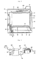
- FIG. 2 illustrates a cross-sectional view of the laundry machine shown in FIG. 1 ;
- FIG. 3 illustrates an enlarged configuration view showing essential portions of the laundry machine shown in FIG. 1 .
- FIGs. 1 to 3 For convenience, a top-loading, electric, condensation dryer is explained as an example, but the present invention is not limited thereto.
- a rotatable drum 20, a motor 70 which drives the drum 20 and a belt 68 are installed inside a cabinet 10 forming an external appearance of the dryer.
- a heater 90 (hereinafter, simply referred to as a "hot air heater") which heats air to produce high-temperature air (hereinafter, referred to as "hot air") and a hot air supply duct 44 which supplies hot air produced in the hot air heater 90 to the drum 20 are installed at specific positions of the cabinet 10.
- an exhaust duct 80 which discharges humid air that has been heat-exchanged with laundry in the drum 20, and a blower unit 60 which sucks the humid air are installed in the cabinet 10.
- a steam generator 200 is installed at a specific position of the cabinet 10 to generate high-temperature steam.
- the cabinet 10 forming an external appearance of the dryer includes a base 12 forming a bottom surface, a pair of side covers 14 vertically installed on the base 12, a front cover 16 and a rear cover 18 respectively installed on the front and rear surfaces of the side covers 14, and a top cover 17 positioned at an upper portion of the side covers 14.
- a control panel 19 having various control switches and the like is generally disposed on the top cover 17 or the front cover 16.
- a door 164 is installed on the front cover 16.
- the rear cover 18 includes a suction port 182 which introduces outside air and an exhaust hole 184 serving a final passage to discharge air in the drum 20 to the outside.
- An inner space of the drum 20 serves as a drying chamber to perform a drying operation, and the drum 20 has a lift 22 therein.
- a front supporter 30 and a rear supporter 40 are installed between the drum 20 and the cabinet 10 (the front cover 16 and the rear cover 18).
- the drum 20 is rotatably installed between the front supporter 30 and the rear supporter 40.
- Sealing members are installed between the front supporter 30 and the drum 20 and between the rear supporter 40 and the drum 20, respectively, to prevent leakage. That is, the front supporter 30 and the rear supporter 40 close the front and rear surfaces of the drum 20 to form the drying chamber and serve to support a front end and a rear end of the drum 20.
- An opening is formed on the front supporter 30 such that the drum 20 communicates with the outside of the dryer.
- the opening is selectively opened and closed by the door 164.
- a lint duct 50 serving as a passage for discharging air of the drum 20 to the outside is connected to the front supporter 30, and a lint filter 52 is installed in the lint duct 50.
- the lint duct 50 is connected to one side of the blower unit 60, and the other side of the blower unit 60 is connected to the exhaust duct 80.
- the exhaust duct 80 communicates with the exhaust hole 184 disposed on the rear cover 18.
- the blower unit 60 when the blower unit 60 is operated, air in the drum 20 is discharged to the outside through the lint duct 50, the exhaust duct 80 and the exhaust hole 184. In this case, foreign matter such as nap is filtered by the lint filter 52.
- the blower unit 60 includes a blower 62 and a blower housing 64, and the blower 62 is connected to and driven by the motor 70 for driving the drum 20.
- An opening 42 generally having a number of through holes is formed on the rear supporter 40.
- the opening 42 is connected to the hot air supply duct 44.
- the hot air supply duct 44 communicates with the drum 20 to serve as a passage for supplying hot air to the drum 20. Accordingly, the hot air heater 90 is installed at a specific position of the hot air supply duct 44.
- the steam generator 200 is installed at a specific position of the cabinet 10 to generate steam and supply the steam into the drum 20.
- the steam generator 200 includes a case for accommodating water therein, a heater (not shown) mounted in the case, a water level sensor (not shown) which measures a water level of the steam generator 200, and a temperature sensor (not shown) which measures a temperature of the steam generator 200.
- the water level sensor includes a common electrode, a low water level electrode and a high water level electrode. The water level sensor detects a high water level and a low water level according to whether the common electrode is electrically connected to the high water level electrode or whether the common electrode is electrically connected to the low water level electrode.
- a water supply hose 220 for supplying water is connected to one side of the steam generator 200 and a steam hose 230 for discharging steam is connected to the other side of the steam generator 200. It is preferable to provide a nozzle 250 at a leading end of the steam hose 230.
- a faucet and a water supply valve are connected to one end of the water supply hose 220.
- a leading end portion of the steam hose 230 or the nozzle 250, that is, a steam discharge port, is disposed at a specific position of the drum 20 to spray steam into the drum 20.
- the nozzle 250 is installed on the rear supporter 40.
- a reservoir 296 for storing water is disposed in the cabinet.
- the reservoir 296 is connected to the faucet through a hose.
- a water level sensor 292 is disposed in the reservoir 296 to sense a water level in the reservoir 296.
- the water level sensor 292 includes a common electrode 293, a low water level electrode 294 and a high water level electrode 295.
- the reservoir 296 has a drain hole disposed at an upper portion thereof.
- the drain hole is connected to a drain line 297.
- the drain hole is disposed at a position higher than a water level sensed by the high water level electrode 295.
- a controller opens the water supply valve to supply water to the reservoir 296.
- the controller closes the water supply valve.
- water supply may be continuously performed over the high water level due to an error generated in the water supply process.
- the excessively supplied water is discharged to the outside of the laundry machine through the drain hole and the drain line 297. Accordingly, there is no problem such as water leakage into the laundry machine.
- the error in the water supply process includes a malfunction of the water supply valve, a malfunction of the water level sensor or the like.
- the drain line 297 may be connected to an outside drain pipe. Further, the drain line 297 may be connected to a drain line of a washing machine.
- the drain line of the washing machine generally includes a drain pump and a drain hose. Further, the drain line 297 may be connected to a tub of the washing machine to discharge water.
- the water stored in the reservoir 296 is supplied to the steam generator 200 by operating a pump 291.
- the controller operates the pump 291 to supply water in the reservoir 296 to the steam generator 200.
- the pump 291 is stopped.
- the heater of the steam generator 200 is turned on to heat water and generate steam.
- the generated steam is supplied to the drum 20.
- the low water level electrode 294 is electrically disconnected to the common electrode 293.
- the controller opens the water supply valve to supply water into the reservoir 296.
- a flowmeter 282 may be installed on the water supply hose which connects the reservoir with the faucet to detect an amount of water supplied into the reservoir.
- a conventional well-known impeller flowmeter 282 can be used as the flowmeter.
- the amount of water supplied through the water supply hose is detected using the rotation number of the impeller.
- the controller receives a signal of the flowmeter 282 and closes the water supply valve when the amount of water reaches a preset amount.
- the reservoir may not have the water level sensor.
- the amount of supplied water is detected by the flowmeter 282 and the amount of water supplied into the steam generator is detected by the operation of the pump, thereby perceiving the amount of water remaining in the reservoir.
- the amount of water remaining in the reservoir may be stored in a memory and used for the controller to control the water supply valve.
- the present invention relates to a laundry machine to wash or dry the laundry. Even though water is excessively supplied to the laundry machine, the water is discharged to the outside through the drain hole of the reservoir, thereby preventing a problem generated due to excessive water supply.
Landscapes
- Engineering & Computer Science (AREA)
- Textile Engineering (AREA)
- Detail Structures Of Washing Machines And Dryers (AREA)
- Control Of Washing Machine And Dryer (AREA)
- Treatment Of Fiber Materials (AREA)
Abstract
Description
- This application claims the benefit of Korean Patent Application No.
10-2007-0096567, filed on September 21, 2007 - The present invention relates to a laundry machine. The laundry machine includes a washing machine, a dryer, a drying and washing machine or the like. Recently, the laundry machine includes a steam generator. The present invention relates more particularly to a laundry machine having a steam generator.
- Generally, washing machines include a pulsator type washing machine and a drum washing machine. Further, the washing machines also include a drying and washing machine which can perform both a washing operation and a drying operation.
- A dryer is an electric home appliance which generally dries wet laundry using high-temperature air. The dryer generally includes a drum which accommodates the laundry therein, a driving device which drives the drum, a heating unit which heats air introduced into the drum, a blower unit which makes the heater air to flow in the drum, and the like.
- The dryers are classified into an electric dryer and a gas-type dryer according to an air heating method, i.e., a heating unit. The electric dryer heats air using electric resistance heat, and the gas-type dryer heats air using heat generated by gas combustion. In another way, the dryers may be classified into a condensation dryer and an exhaust dryer. In the condensation dryer, humid air which has been heat-exchanged with the laundry in the drum is circulated without being discharged to the outside, and the humid air is converted into condensed water in a separate condenser by heat exchange with outside air to be discharged to the outside. In the exhaust dryer, humid air which has been heat-exchanged with the laundry in the drum is directly discharged out of the dryer.
- A conventional laundry machine may include a steam generator. A washing machine using steam in the washing operation has a good washing performance. The dryer may also include a steam generator.
- When water is supplied into the laundry machine to supply steam into the drum, water may be excessively supplied and introduced into the drum.
- For example, when water is excessively supplied into the steam generator, water may overflow through a steam line. Particularly, when water is supplied into the steam generator through a faucet and a water supply valve, if the water supply valve is out of order, water may continuously flow into the steam generator, thereby causing overflow. In case of a dryer, overflowing water may be introduced into the drum to get the laundry wet. Further, since the dryer generally does not have a drain line, differently from the washing machine, the problem becomes worse.
- Also in the washing machine, water may overflow the steam generator due to an error in the water supply to flow into the tub, thereby causing a problem.
- Accordingly, the present invention is directed to a laundry machine that substantially obviates one or more problems due to limitations and disadvantages of the related art.
- Additional advantages, objects, and features of the invention will be set forth in part in the description which follows and in part will become apparent to those having ordinary skill in the art upon examination of the following or may be learned from practice of the invention. The objectives and other advantages of the invention may be realized and attained by the structure particularly pointed out in the written description and claims hereof as well as the appended drawings.
- An embodiment of the present invention comprises a drum in which laundry is put; a reservoir to hold water for supplying moisture into the drum, the reservoir having a drain hole at a predetermined level of height; and a drain line connected to the drain hole.
- Even though water is supplied to the reservoir over to a required level, the water is discharged through the drain line via the drain hole. The drain line can be connected to an outside drain pipe such as an indoor drain pipe. Further, the drain line can be connected to a tub or a drain line of a washing machine which is placed near the laundry machine. Generally, since the washing machine includes its own drain line for discharging water in its tub, the drain line can be used to discharge the over-supplied water of the laundry machine.
- The laundry machine can further comprise a water supply line to supply water to the reservoir. The water supply line can be connected between a faucet and the reservoir. The laundry machine can further comprise a water supply valve in the water supply line.
- The water supply valve can be controlled to be closed before a water level of the reservoir reaches the drain hole. For this, the water supply valve can be controlled based on an amount of water to be supplied into the reservoir. For example, the water supply valve can be controlled to be closed when the amount of water supplied into the reservoir is equal to or larger than a preset amount. The laundry machine can further comprise a flowmeter in the water supply line to measure an amount of water supplied to the reservoir. The flowmeter can be a conventional well-known impeller flowmeter. The impeller flowmeter detects the amount of water based on the number of rotation of the impeller.
- The laundry machine can further comprise a water level sensor to sense a water level of the reservoir. The water supply valve is controlled to be closed when the water level of the reservoir reaches a preset level.
- Further, the water supply valve can be controlled according to time. The water is not supplied over a predetermined period of time such that the water level of the reservoir does not reach the drain hole.
- The laundry machine can further comprise a fine water droplet generator to supply moisture into the drum with fine droplets of water. The fine water droplet generator makes fine droplets with the supplied water.
- The fine water droplet generator can include a steam generator.
- The fine water droplet generator is connected to the reservoir. The laundry machine can further comprise a pump to supply the water from the reservoir to the fine water droplet generator.
- Alternatively, the fine water droplet generator can include a spray. The spray changes water into fine droplets. The spray can be connected to the reservoir through a hose to directly spray the droplets of the water into the drum. For example, the spray can include a generally well-known spray nozzle which turns pressurized water into fine droplets. Further, the fine water droplet generator can be a device which changes water into fine droplets of water by ultrasonic vibration as a method mainly used in a humidifier.
- Even though water is over-supplied to the laundry machine, the water is discharged to the outside through the drain hole of the reservoir, thereby preventing a problem generated due to over-supplying of water.
- It is to be understood that both the foregoing general description and the following detailed description of the present invention are exemplary and explanatory and are intended to provide further explanation of the invention as claimed.
- The accompanying drawings, which are included to provide a further understanding of the invention and are incorporated in and constitute a part of this application, illustrate embodiment(s) of the invention and together with the description serve to explain the principle of the invention. In the drawings:
-
FIG. 1 illustrates a laundry machine according to an embodiment of the present invention; -
FIG. 2 illustrates a cross-sectional view of the laundry machine shown inFIG. 1 ; and -
FIG. 3 illustrates an enlarged configuration view showing essential portions of the laundry machine shown inFIG. 1 . - Reference will now be made in detail to the preferred embodiments of the present invention, examples of which are illustrated in the accompanying drawings. Wherever possible, the same reference numbers will be used throughout the drawings to refer to the same or like parts.
- Hereinafter, a laundry machine according to an embodiment of the present invention will be described with reference to
FIGs. 1 to 3 . For convenience, a top-loading, electric, condensation dryer is explained as an example, but the present invention is not limited thereto. - A
rotatable drum 20, amotor 70 which drives thedrum 20 and abelt 68 are installed inside acabinet 10 forming an external appearance of the dryer. Further, a heater 90 (hereinafter, simply referred to as a "hot air heater") which heats air to produce high-temperature air (hereinafter, referred to as "hot air") and a hot air supply duct 44 which supplies hot air produced in thehot air heater 90 to thedrum 20 are installed at specific positions of thecabinet 10. Further, anexhaust duct 80 which discharges humid air that has been heat-exchanged with laundry in thedrum 20, and ablower unit 60 which sucks the humid air are installed in thecabinet 10. Meanwhile, asteam generator 200 is installed at a specific position of thecabinet 10 to generate high-temperature steam. Although an indirect drive type dryer which rotates thedrum 20 using themotor 70 and thebelt 68 is shown and described in this embodiment for convenience, the present invention is not limited thereto. That is, a direct drive type dryer which directly rotates thedrum 20 by a motor directly connected to the rear surface of thedrum 20 may be applied to the present invention. - The respective components are described in detail below.
- The
cabinet 10 forming an external appearance of the dryer includes a base 12 forming a bottom surface, a pair of side covers 14 vertically installed on thebase 12, afront cover 16 and arear cover 18 respectively installed on the front and rear surfaces of the side covers 14, and atop cover 17 positioned at an upper portion of the side covers 14. Acontrol panel 19 having various control switches and the like is generally disposed on thetop cover 17 or thefront cover 16. Adoor 164 is installed on thefront cover 16. Therear cover 18 includes asuction port 182 which introduces outside air and anexhaust hole 184 serving a final passage to discharge air in thedrum 20 to the outside. - An inner space of the
drum 20 serves as a drying chamber to perform a drying operation, and thedrum 20 has alift 22 therein. - Meanwhile, a
front supporter 30 and arear supporter 40 are installed between thedrum 20 and the cabinet 10 (thefront cover 16 and the rear cover 18). Thedrum 20 is rotatably installed between thefront supporter 30 and therear supporter 40. Sealing members (not shown) are installed between thefront supporter 30 and thedrum 20 and between therear supporter 40 and thedrum 20, respectively, to prevent leakage. That is, thefront supporter 30 and therear supporter 40 close the front and rear surfaces of thedrum 20 to form the drying chamber and serve to support a front end and a rear end of thedrum 20. - An opening is formed on the
front supporter 30 such that thedrum 20 communicates with the outside of the dryer. The opening is selectively opened and closed by thedoor 164. Further, alint duct 50 serving as a passage for discharging air of thedrum 20 to the outside is connected to thefront supporter 30, and alint filter 52 is installed in thelint duct 50. Thelint duct 50 is connected to one side of theblower unit 60, and the other side of theblower unit 60 is connected to theexhaust duct 80. Theexhaust duct 80 communicates with theexhaust hole 184 disposed on therear cover 18. Accordingly, when theblower unit 60 is operated, air in thedrum 20 is discharged to the outside through thelint duct 50, theexhaust duct 80 and theexhaust hole 184. In this case, foreign matter such as nap is filtered by thelint filter 52. Generally, theblower unit 60 includes ablower 62 and ablower housing 64, and theblower 62 is connected to and driven by themotor 70 for driving thedrum 20. - An
opening 42 generally having a number of through holes is formed on therear supporter 40. Theopening 42 is connected to the hot air supply duct 44. The hot air supply duct 44 communicates with thedrum 20 to serve as a passage for supplying hot air to thedrum 20. Accordingly, thehot air heater 90 is installed at a specific position of the hot air supply duct 44. - Meanwhile, the
steam generator 200 is installed at a specific position of thecabinet 10 to generate steam and supply the steam into thedrum 20. - The
steam generator 200 includes a case for accommodating water therein, a heater (not shown) mounted in the case, a water level sensor (not shown) which measures a water level of thesteam generator 200, and a temperature sensor (not shown) which measures a temperature of thesteam generator 200. The water level sensor includes a common electrode, a low water level electrode and a high water level electrode. The water level sensor detects a high water level and a low water level according to whether the common electrode is electrically connected to the high water level electrode or whether the common electrode is electrically connected to the low water level electrode. - A water supply hose 220 for supplying water is connected to one side of the
steam generator 200 and asteam hose 230 for discharging steam is connected to the other side of thesteam generator 200. It is preferable to provide anozzle 250 at a leading end of thesteam hose 230. A faucet and a water supply valve are connected to one end of the water supply hose 220. A leading end portion of thesteam hose 230 or thenozzle 250, that is, a steam discharge port, is disposed at a specific position of thedrum 20 to spray steam into thedrum 20. In this embodiment, thenozzle 250 is installed on therear supporter 40. - Further, a
reservoir 296 for storing water is disposed in the cabinet. Thereservoir 296 is connected to the faucet through a hose. Awater level sensor 292 is disposed in thereservoir 296 to sense a water level in thereservoir 296. Thewater level sensor 292 includes acommon electrode 293, a lowwater level electrode 294 and a highwater level electrode 295. - Further, the
reservoir 296 has a drain hole disposed at an upper portion thereof. The drain hole is connected to adrain line 297. In this embodiment, the drain hole is disposed at a position higher than a water level sensed by the highwater level electrode 295. - A process of supplying water to the reservoir is described below.
- A controller opens the water supply valve to supply water to the
reservoir 296. When it is determined that the water level in thereservoir 296 reaches a high water level based on a signal of thewater level sensor 292, the controller closes the water supply valve. In this case, water supply may be continuously performed over the high water level due to an error generated in the water supply process. The excessively supplied water is discharged to the outside of the laundry machine through the drain hole and thedrain line 297. Accordingly, there is no problem such as water leakage into the laundry machine. The error in the water supply process includes a malfunction of the water supply valve, a malfunction of the water level sensor or the like. - In this case, although not shown in the drawings, the
drain line 297 may be connected to an outside drain pipe. Further, thedrain line 297 may be connected to a drain line of a washing machine. The drain line of the washing machine generally includes a drain pump and a drain hose. Further, thedrain line 297 may be connected to a tub of the washing machine to discharge water. - The water stored in the
reservoir 296 is supplied to thesteam generator 200 by operating apump 291. In order to use steam, the controller operates thepump 291 to supply water in thereservoir 296 to thesteam generator 200. When it is determined that a water level in thesteam generator 200 reaches a preset level by the water level sensor, thepump 291 is stopped. Then, the heater of thesteam generator 200 is turned on to heat water and generate steam. The generated steam is supplied to thedrum 20. - When the water level gradually decreases as water in the
reservoir 296 is used, the lowwater level electrode 294 is electrically disconnected to thecommon electrode 293. In this case, when it is necessary to supply water into thereservoir 296, the controller opens the water supply valve to supply water into thereservoir 296. - Meanwhile, a
flowmeter 282 may be installed on the water supply hose which connects the reservoir with the faucet to detect an amount of water supplied into the reservoir. Generally, a conventional well-knownimpeller flowmeter 282 can be used as the flowmeter. The amount of water supplied through the water supply hose is detected using the rotation number of the impeller. The controller receives a signal of theflowmeter 282 and closes the water supply valve when the amount of water reaches a preset amount. In case of using theflowmeter 282, the reservoir may not have the water level sensor. The amount of supplied water is detected by theflowmeter 282 and the amount of water supplied into the steam generator is detected by the operation of the pump, thereby perceiving the amount of water remaining in the reservoir. The amount of water remaining in the reservoir may be stored in a memory and used for the controller to control the water supply valve. - The present invention relates to a laundry machine to wash or dry the laundry. Even though water is excessively supplied to the laundry machine, the water is discharged to the outside through the drain hole of the reservoir, thereby preventing a problem generated due to excessive water supply.
- It will be apparent to those skilled in the art that various modifications and variations can be made in the present invention without departing from the spirit or scope of the inventions. Thus, it is intended that the present invention covers the modifications and variations of this invention provided they come within the scope of the appended claims and their equivalents.
Claims (13)
- A laundry machine comprising:a drum in which laundry is put;a reservoir to hold water for supplying moisture into the drum, the reservoir having a drain hole at a predetermined level of height; anda drain line connected to the drain hole.
- The laundry machine of claim 1, further comprising a water supply line to supply water through from a faucet to the reservoir.
- The laundry machine of claim 1, wherein the drain line is configured to be connected to a tub or a drain line of a washing machine.
- The laundry machine of claim 1, the drain line is configured to be connected to an outside drain pipe.
- The laundry machine of claim 1, further comprising a fine water droplet generator to generate fine droplets of water.
- The laundry machine of claim 5, further comprising a pump to supply the water from the reservoir to the fine water droplet generator.
- The laundry machine of claim 5, wherein the fine water droplet generator comprises a steam generator to generate steam.
- The laundry machine of claim 5, wherein the fine water droplet generator comprises a nozzle which turns water into fine droplets.
- The laundry machine of claim 2, further comprising a water supply valve in the water supply line, wherein the water supply valve is controlled to be closed before a water level of the reservoir reaches the drain hole.
- The laundry machine of claim 9, further comprising a water level sensor to sense a water level of the reservoir, wherein the water supply valve is controlled to be closed when the sensed water level reaches a preset level below the drain hole.
- The laundry machine of claim 9, wherein the water supply valve is controlled according to time.
- The laundry machine of claim 9, further comprising an instrument to measure an amount of water supplied to the reservoir.
- The laundry machine of claim 12, wherein the instrument comprises an impeller flowmeter placed in the water supply line.
Applications Claiming Priority (1)
| Application Number | Priority Date | Filing Date | Title |
|---|---|---|---|
| KR1020070096567A KR20090030901A (en) | 2007-09-21 | 2007-09-21 | Laundry machine |
Publications (3)
| Publication Number | Publication Date |
|---|---|
| EP2039823A2 true EP2039823A2 (en) | 2009-03-25 |
| EP2039823A3 EP2039823A3 (en) | 2009-06-17 |
| EP2039823B1 EP2039823B1 (en) | 2014-01-22 |
Family
ID=40210533
Family Applications (1)
| Application Number | Title | Priority Date | Filing Date |
|---|---|---|---|
| EP08010906.9A Active EP2039823B1 (en) | 2007-09-21 | 2008-06-16 | Laundry machine |
Country Status (4)
| Country | Link |
|---|---|
| US (1) | US20090100882A1 (en) |
| EP (1) | EP2039823B1 (en) |
| KR (1) | KR20090030901A (en) |
| CN (1) | CN101392445B (en) |
Cited By (3)
| Publication number | Priority date | Publication date | Assignee | Title |
|---|---|---|---|---|
| WO2013145063A1 (en) | 2012-03-30 | 2013-10-03 | パナソニック株式会社 | Clothing treatment device |
| WO2013145067A1 (en) | 2012-03-30 | 2013-10-03 | パナソニック株式会社 | Clothes treatment device |
| EP2764814A1 (en) * | 2013-02-08 | 2014-08-13 | AWECO Appliance Entwicklungs- und Engineering GmbH | Household appliance |
Families Citing this family (19)
| Publication number | Priority date | Publication date | Assignee | Title |
|---|---|---|---|---|
| KR100556503B1 (en) * | 2002-11-26 | 2006-03-03 | 엘지전자 주식회사 | Control Method of Drying Time for Dryer |
| DE10260149A1 (en) * | 2002-12-20 | 2004-07-01 | BSH Bosch und Siemens Hausgeräte GmbH | Device for determining the conductivity of laundry, clothes dryer and method for preventing layer formation on electrodes |
| DE102007007354B4 (en) * | 2006-02-20 | 2013-10-10 | Lg Electronics Inc. | Clothes dryer and method of control |
| KR100830514B1 (en) | 2006-06-12 | 2008-05-21 | 엘지전자 주식회사 | laundry dryer and method for controlling the same |
| KR101341461B1 (en) * | 2006-12-15 | 2013-12-16 | 엘지전자 주식회사 | Steam laundry dryer |
| US7997006B2 (en) * | 2007-01-12 | 2011-08-16 | Lg Electronics Inc. | Laundry machine and control method thereof |
| KR101432585B1 (en) * | 2007-03-06 | 2014-08-22 | 엘지전자 주식회사 | Apparatus for collecting foreign materials and method for cleaning the same |
| KR101348719B1 (en) | 2007-03-06 | 2014-01-16 | 엘지전자 주식회사 | Apparatus for collecting foreign materials |
| KR101360205B1 (en) * | 2007-03-06 | 2014-02-12 | 엘지전자 주식회사 | Apparatus for collecting foreign materials and washing machine having the same |
| KR101441917B1 (en) * | 2007-03-06 | 2014-09-29 | 엘지전자 주식회사 | Apparatus for collecting foreign materials and washing machine having the same |
| KR101348718B1 (en) | 2007-03-06 | 2014-01-10 | 엘지전자 주식회사 | Apparatus for collecting foreign materials and washing machine having the same |
| WO2012033880A1 (en) * | 2010-09-08 | 2012-03-15 | Direct Drivehead, Inc. | System and method for controlling fluid pumps to achieve desired levels |
| CN102587092A (en) * | 2012-01-16 | 2012-07-18 | 贝国寅 | Digital water level control device and water control method for washing machine |
| EP2762634B1 (en) * | 2013-02-01 | 2017-08-30 | Panasonic Corporation | Laundry dryer |
| ES2564024T3 (en) * | 2013-02-13 | 2016-03-17 | Lg Electronics Inc. | Machine for washing the laundry and its control procedure |
| US10738409B2 (en) * | 2017-10-31 | 2020-08-11 | Whirlpool Corporation | Laundry treating appliance with a sensor |
| CN110393490B (en) * | 2018-04-24 | 2022-05-06 | 天津海尔洗涤电器有限公司 | Washing equipment control method and washing equipment |
| TR202010838A2 (en) * | 2020-07-08 | 2020-08-21 | Dogan Buelbuel | A DRYER THAT USES A HUMIDIFIER TO REMOVE MOISTURE |
| CN115478424A (en) * | 2022-09-20 | 2022-12-16 | 浙江一挺电器股份有限公司 | Power-off protection long-service-life garment steamer and control method thereof |
Citations (2)
| Publication number | Priority date | Publication date | Assignee | Title |
|---|---|---|---|---|
| WO2006129916A1 (en) | 2005-05-31 | 2006-12-07 | Lg Electronics Inc. | Laundry machine |
| EP1813704A1 (en) | 2006-01-26 | 2007-08-01 | LG Electronics Inc. | Steam generator for a washing machine |
-
2007
- 2007-09-21 KR KR1020070096567A patent/KR20090030901A/en not_active Application Discontinuation
-
2008
- 2008-06-16 EP EP08010906.9A patent/EP2039823B1/en active Active
- 2008-07-29 CN CN200810144120.3A patent/CN101392445B/en not_active Expired - Fee Related
- 2008-09-12 US US12/232,268 patent/US20090100882A1/en not_active Abandoned
Patent Citations (2)
| Publication number | Priority date | Publication date | Assignee | Title |
|---|---|---|---|---|
| WO2006129916A1 (en) | 2005-05-31 | 2006-12-07 | Lg Electronics Inc. | Laundry machine |
| EP1813704A1 (en) | 2006-01-26 | 2007-08-01 | LG Electronics Inc. | Steam generator for a washing machine |
Cited By (5)
| Publication number | Priority date | Publication date | Assignee | Title |
|---|---|---|---|---|
| WO2013145063A1 (en) | 2012-03-30 | 2013-10-03 | パナソニック株式会社 | Clothing treatment device |
| WO2013145067A1 (en) | 2012-03-30 | 2013-10-03 | パナソニック株式会社 | Clothes treatment device |
| EP2662484A1 (en) * | 2012-03-30 | 2013-11-13 | Panasonic Corporation | Clothing treatment device |
| EP2662484A4 (en) * | 2012-03-30 | 2014-04-23 | Panasonic Corp | Clothing treatment device |
| EP2764814A1 (en) * | 2013-02-08 | 2014-08-13 | AWECO Appliance Entwicklungs- und Engineering GmbH | Household appliance |
Also Published As
| Publication number | Publication date |
|---|---|
| US20090100882A1 (en) | 2009-04-23 |
| CN101392445A (en) | 2009-03-25 |
| KR20090030901A (en) | 2009-03-25 |
| EP2039823A3 (en) | 2009-06-17 |
| CN101392445B (en) | 2015-08-12 |
| EP2039823B1 (en) | 2014-01-22 |
Similar Documents
| Publication | Publication Date | Title |
|---|---|---|
| EP2039823B1 (en) | Laundry machine | |
| EP2039824B1 (en) | Laundry machine | |
| US7930838B2 (en) | Laundry dryer | |
| KR100866884B1 (en) | Controlling method of a clothes dryer for detecting an amount of laundry put therein and a clothes dryer with the same | |
| KR101319874B1 (en) | control method of laundry dryer | |
| US7520145B2 (en) | Washing machine combined with dryer and controlling method thereof | |
| US8312642B2 (en) | Controlling method of a steam generator and a laundry machine with the same | |
| US8250777B2 (en) | Device of supplying water for laundry dryer and method for controlling the same | |
| KR20070023888A (en) | Operating method for laundry machine | |
| KR20060061974A (en) | Apparatus for remove wrinkles of clothes and method thereof | |
| US20080141553A1 (en) | Laundry machine and control method thereof | |
| KR20060085537A (en) | Method to remove wrinkles of clothes | |
| KR100640811B1 (en) | Device of supplying water for laundry dryer and method for controlling the same | |
| KR100808868B1 (en) | Method to remove wrinkles of clothes | |
| EP3296452B1 (en) | Washing machine with drying apparatus and method of controlling the same | |
| KR101208531B1 (en) | laundry dryer | |
| KR100833866B1 (en) | Steam laundry dryer | |
| KR20080032378A (en) | Steam washing method for washing machine | |
| JPH09173697A (en) | Drum type washing and drying machine | |
| KR20060062407A (en) | Control method of washing machine with steam generation device | |
| KR101072029B1 (en) | Clothes dryer having fragrance supplying module | |
| KR100804108B1 (en) | Steam generator and control method thereof | |
| KR20080007844A (en) | Laundry dryer | |
| AU2006341533A1 (en) | Device of supplying water for laundry dryer and method for controlling the same |
Legal Events
| Date | Code | Title | Description |
|---|---|---|---|
| PUAI | Public reference made under article 153(3) epc to a published international application that has entered the european phase |
Free format text: ORIGINAL CODE: 0009012 |
|
| AK | Designated contracting states |
Kind code of ref document: A2 Designated state(s): AT BE BG CH CY CZ DE DK EE ES FI FR GB GR HR HU IE IS IT LI LT LU LV MC MT NL NO PL PT RO SE SI SK TR |
|
| AX | Request for extension of the european patent |
Extension state: AL BA MK RS |
|
| PUAL | Search report despatched |
Free format text: ORIGINAL CODE: 0009013 |
|
| AK | Designated contracting states |
Kind code of ref document: A3 Designated state(s): AT BE BG CH CY CZ DE DK EE ES FI FR GB GR HR HU IE IS IT LI LT LU LV MC MT NL NO PL PT RO SE SI SK TR |
|
| AX | Request for extension of the european patent |
Extension state: AL BA MK RS |
|
| 17P | Request for examination filed |
Effective date: 20091215 |
|
| 17Q | First examination report despatched |
Effective date: 20100111 |
|
| AKX | Designation fees paid |
Designated state(s): DE FR |
|
| GRAP | Despatch of communication of intention to grant a patent |
Free format text: ORIGINAL CODE: EPIDOSNIGR1 |
|
| INTG | Intention to grant announced |
Effective date: 20131004 |
|
| GRAS | Grant fee paid |
Free format text: ORIGINAL CODE: EPIDOSNIGR3 |
|
| GRAA | (expected) grant |
Free format text: ORIGINAL CODE: 0009210 |
|
| AK | Designated contracting states |
Kind code of ref document: B1 Designated state(s): DE FR |
|
| REG | Reference to a national code |
Ref country code: DE Ref legal event code: R096 Ref document number: 602008030032 Country of ref document: DE Effective date: 20140306 |
|
| REG | Reference to a national code |
Ref country code: DE Ref legal event code: R097 Ref document number: 602008030032 Country of ref document: DE |
|
| PLBE | No opposition filed within time limit |
Free format text: ORIGINAL CODE: 0009261 |
|
| STAA | Information on the status of an ep patent application or granted ep patent |
Free format text: STATUS: NO OPPOSITION FILED WITHIN TIME LIMIT |
|
| 26N | No opposition filed |
Effective date: 20141023 |
|
| REG | Reference to a national code |
Ref country code: DE Ref legal event code: R097 Ref document number: 602008030032 Country of ref document: DE Effective date: 20141023 |
|
| REG | Reference to a national code |
Ref country code: FR Ref legal event code: PLFP Year of fee payment: 9 |
|
| REG | Reference to a national code |
Ref country code: FR Ref legal event code: PLFP Year of fee payment: 10 |
|
| REG | Reference to a national code |
Ref country code: FR Ref legal event code: PLFP Year of fee payment: 11 |
|
| PGFP | Annual fee paid to national office [announced via postgrant information from national office to epo] |
Ref country code: FR Payment date: 20220512 Year of fee payment: 15 |
|
| PGFP | Annual fee paid to national office [announced via postgrant information from national office to epo] |
Ref country code: DE Payment date: 20230508 Year of fee payment: 16 |