EP2036838B1 - Lid assembly for a fluid container - Google Patents
Lid assembly for a fluid container Download PDFInfo
- Publication number
- EP2036838B1 EP2036838B1 EP08007860A EP08007860A EP2036838B1 EP 2036838 B1 EP2036838 B1 EP 2036838B1 EP 08007860 A EP08007860 A EP 08007860A EP 08007860 A EP08007860 A EP 08007860A EP 2036838 B1 EP2036838 B1 EP 2036838B1
- Authority
- EP
- European Patent Office
- Prior art keywords
- lid
- lid assembly
- container
- assembly according
- skirt
- Prior art date
- Legal status (The legal status is an assumption and is not a legal conclusion. Google has not performed a legal analysis and makes no representation as to the accuracy of the status listed.)
- Active
Links
- 239000012530 fluid Substances 0.000 title description 2
- 239000007788 liquid Substances 0.000 claims description 9
- 229920003023 plastic Polymers 0.000 claims description 4
- 239000004033 plastic Substances 0.000 claims description 4
- 239000011324 bead Substances 0.000 claims description 3
- 238000007789 sealing Methods 0.000 claims description 3
- 239000000463 material Substances 0.000 claims description 2
- 230000002787 reinforcement Effects 0.000 claims 3
- 230000000295 complement effect Effects 0.000 claims 1
- 230000037431 insertion Effects 0.000 claims 1
- 238000003780 insertion Methods 0.000 claims 1
- 230000003014 reinforcing effect Effects 0.000 description 9
- 230000002093 peripheral effect Effects 0.000 description 5
- 229920001971 elastomer Polymers 0.000 description 3
- 239000002699 waste material Substances 0.000 description 3
- 230000002349 favourable effect Effects 0.000 description 2
- 239000003921 oil Substances 0.000 description 2
- 230000006641 stabilisation Effects 0.000 description 2
- 238000011105 stabilization Methods 0.000 description 2
- 238000010521 absorption reaction Methods 0.000 description 1
- 230000000712 assembly Effects 0.000 description 1
- 238000000429 assembly Methods 0.000 description 1
- 230000009286 beneficial effect Effects 0.000 description 1
- 238000011109 contamination Methods 0.000 description 1
- 239000000806 elastomer Substances 0.000 description 1
- 239000003925 fat Substances 0.000 description 1
- 238000001746 injection moulding Methods 0.000 description 1
- 239000003351 stiffener Substances 0.000 description 1
Images


Classifications
-
- B—PERFORMING OPERATIONS; TRANSPORTING
- B65—CONVEYING; PACKING; STORING; HANDLING THIN OR FILAMENTARY MATERIAL
- B65F—GATHERING OR REMOVAL OF DOMESTIC OR LIKE REFUSE
- B65F1/00—Refuse receptacles; Accessories therefor
- B65F1/14—Other constructional features; Accessories
- B65F1/16—Lids or covers
- B65F1/1615—Lids or covers with means for locking, fastening or permanently closing thereof
-
- B—PERFORMING OPERATIONS; TRANSPORTING
- B65—CONVEYING; PACKING; STORING; HANDLING THIN OR FILAMENTARY MATERIAL
- B65D—CONTAINERS FOR STORAGE OR TRANSPORT OF ARTICLES OR MATERIALS, e.g. BAGS, BARRELS, BOTTLES, BOXES, CANS, CARTONS, CRATES, DRUMS, JARS, TANKS, HOPPERS, FORWARDING CONTAINERS; ACCESSORIES, CLOSURES, OR FITTINGS THEREFOR; PACKAGING ELEMENTS; PACKAGES
- B65D43/00—Lids or covers for rigid or semi-rigid containers
- B65D43/14—Non-removable lids or covers
- B65D43/22—Devices for holding in closed position, e.g. clips
-
- B—PERFORMING OPERATIONS; TRANSPORTING
- B65—CONVEYING; PACKING; STORING; HANDLING THIN OR FILAMENTARY MATERIAL
- B65F—GATHERING OR REMOVAL OF DOMESTIC OR LIKE REFUSE
- B65F1/00—Refuse receptacles; Accessories therefor
- B65F1/14—Other constructional features; Accessories
- B65F2001/1653—Constructional features of lids or covers
- B65F2001/1676—Constructional features of lids or covers relating to means for sealing the lid or cover, e.g. against escaping odors
-
- B—PERFORMING OPERATIONS; TRANSPORTING
- B65—CONVEYING; PACKING; STORING; HANDLING THIN OR FILAMENTARY MATERIAL
- B65F—GATHERING OR REMOVAL OF DOMESTIC OR LIKE REFUSE
- B65F2240/00—Types of refuse collected
- B65F2240/142—Grease
-
- B—PERFORMING OPERATIONS; TRANSPORTING
- B65—CONVEYING; PACKING; STORING; HANDLING THIN OR FILAMENTARY MATERIAL
- B65F—GATHERING OR REMOVAL OF DOMESTIC OR LIKE REFUSE
- B65F2240/00—Types of refuse collected
- B65F2240/152—Oil
Definitions
- the invention relates to a lid arrangement for a container for liquids, which has a downwardly directed areawise oblique edge, in regions according to the preamble of claim 1.
- a generic lid assembly for a commercial garbage container is known with a specially designed lid, wherein a seal between two peripheral edges of the lid is arranged both edges embrace a protruding peripheral edge of the container opening. So that the lid can not jump open, it is secured by three acting in the manner of toggle fasteners locks. These connect the lid to the container, wherein a ring is hinged by means of a flange movable on the lid and engages behind a riveted hook on the container.
- the locking hook is formed on the cover and
- the locking hook is located centrally on the edge opposite the lid hinges.
- the present lid assembly is particularly beneficial when used on tons that can be used to dispose of waste liquids, including fats or oils. It is advantageous that the lid has two mounting brackets in the front region of the lid, which are integrally formed on the lid. Due to the one-piece design, it is possible for the user of the lid assembly of the invention to close without additional measures the lid by a simple downward pressing. The integrally formed on the cover mounting brackets are also in a handle to solve again.
- the lid assembly is made of plastic, for example by injection molding, so that the mounting brackets formed thereon are molded on could be.
- the cover assembly of the invention can be placed on existing, standardized containers, such as garbage bins.
- Garbage bins are made in accordance with EN 840 so that the lid assembly of the invention is applicable to all such barrels.
- the two laterally disposed mounting brackets extend downwardly from the lid over an upper peripheral edge of the container Fig. 1 negative Z-direction) to one at the upper peripheral edge of the barrel down or possibly in a non-standard tons possibly also to the side (in Fig. 1 X-direction) behind the protruding edge.
- the mounting brackets are elastically bend outward and snap in a closed position of the lid with their hooked ends behind the edge in a closed position. To close the lid so it is only necessary to push the lid down until the mounting brackets engage. To open the lid, the mounting brackets are pushed outward with hand force and simultaneously moved upward, so that the latching connection of the mounting brackets is released at the peripheral edge of the barrel. Due to the elasticity of the mounting brackets, the closed position can be repeated as often as desired.
- At least one fastening arm is provided on the cover arrangement, which extends over a predetermined length over the surface of the lid and is simultaneously supported on the holding device of the container or is guided thereon.
- the attachment arm can be formed integrally with the cover assembly or attached as an additional part in retrospect.
- the lid assembly of the invention may additionally have an apron, which projects into the container.
- the skirt may have a fit to the inner wall of the container. The apron projecting into the container serves, in particular, to prevent a liquid bouncing against the lid assembly with great force (for example when the container falls over) from acting completely on the lid seal, but largely absorbed by the apron extending in the circumferential direction along the inner wall of the container becomes.
- the skirt may be slightly spaced from the inner wall of the container. It then makes sense to provide an additional seal between the inner wall of the container and the apron.
- this front skirt part can also be elastically movable, so that it can always rest against the inner wall of the container.
- it could also be provided to slit the corners of the apron in the front area.
- the lid arrangement is also sealed over its outer edge against unwanted liquid leakage.
- the lid arrangement has a downwardly directed groove which extends over a rim extending upwardly from the container.
- a seal preferably a rubber seal is arranged.
- the groove may be formed differently deep over its length, so that the seal arranged therein at different locations at different depths in the groove. In this way, from the projecting into the groove edge of the container, which has a constant height, at different points of the seal a different pressure force exercised, which leads to special tightness over the entire circumference of the lid assembly.
- the groove on all four Rare the lid assembly may be evenly cambered.
- the camber on each longitudinal side may have a size of 2 to 5 mm.
- the skirt may be an extension of the inner web of the groove.
- reinforcing struts on the underside of the lid, which can be integrally formed with the lid.
- the reinforcing struts can be formed in any pattern, for example star or cross-shaped.
- lid assembly on conventional, standardized containers, such as refuse, so that no additional costs incurred for the development of new tons and equipment.
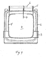
- Fig. 1 the lid assembly 1 of the invention is shown on a like a garbage bin container 2 in a perspective view obliquely from above.
- the cover assembly preferably made of plastic, can be placed on the container 2 and fastened thereto with two fixing clips 3 integrally formed on the cover assembly 1.
- hinge arms 5 extend outwardly in the direction (Y direction) of a holding device 6 provided on the container 2 and are connected thereto.
- the connection of the hinge arms 5 to the holding device 6 is provided by hinge pins 6 ", which are pressed from the side through openings 5 'of the hinge arms 5 into bores 6' of the holding device 6.
- the cover 4 is, as is known from commercial garbage cans. to open by a rotational movement about the holding device 6.
- the integrally formed on the lid 4 of the lid assembly 1 mounting brackets 3 extend from the lid 4 initially in the X direction to the outside, form an arc around the edge of the lid assembly 1 and continue to extend substantially vertically in the Z direction down to over its length to overlap both the lid assembly 1 and the upper edge of the container 2.
- the mounting brackets 3 At its free end 3 ', the mounting brackets 3 have a hook shape (see. Fig. 2 ), with which they engage behind an edge with an oblique edge of the container 2.
- the lower edge of the mounting brackets 3 is chamfered in the Y direction.
- the Befest onlysklammem 3 are preferably made of plastic and elastic, so that they can bend when closing the lid 4, when they slide over the outer edge of the container 2, to the outside and then the edge or the edge or the like of the container 2 alone can engage behind by their elastic restoring force as soon as the closed position of the lid 4 is reached.
- the lid is first pressed down and then the hook-shaped ends 3 'bent with hand force to the outside and the lid 4 simultaneously moved upwards.
- the depression is made possible by a flexible soft seal between cover and barrel explained in more detail below.
- one or more reinforcing ribs 4 ' extending over at least part of the circumference of the lid 4 are provided.
- the fastening brackets 3 adjoin the reinforcing rib 4 ', so that the elastic forces of the fastening brackets 3 can also be supported by the reinforcing rib 4' at the rear, ie toward the center of the lid.
- At least one fastening arm 7 is provided in the lid assembly 4, which extends over a predetermined length of the rear part of the lid assembly 1 in the Y direction.
- the mounting arm 7 is integrally formed with the cover 4 and supported and guided on the rear side of the holding device 6 designed as a rod.
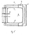
- Fig. 2 shows the lid assembly 1 in a perspective view obliquely from above.
- the lid 4 of the lid assembly 1 is closed.
- one fastening clip 3 is provided on the cover 4 in the front region on the left and right sides.
- the fastening clips 3 have lateral stiffeners 3 "on their side edges, which ensure the necessary rigidity and stability for securely holding the engagement position of the hook-shaped free ends 3 ' (see. Fig. 1 ) engages and is supported on this.
- the lid assembly 1 has a downwardly directed skirt 8, which is insertable into the interior of a container 2.
- the skirt 8 is integrally formed on the lid assembly 1 and dimensioned so that it rests against the inner wall of the container 2 in a fit.
- the skirt 8 has a depth (in the Z direction) of 10 to 150 mm, more preferably 70-100 mm.
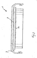
- Fig. 3 shows the lid assembly 1 in a perspective view obliquely from below.
- the cover assembly 1 has a downwardly directed groove 9, in which a seal 10, preferably soft seal, extends from a suitable elastomer.
- the groove 9 is formed so that it can be placed on a container 2 upwardly extending edge and thus a seal of the lid assembly 1 relative to the interior of the container 2 is ensured.
- the groove 9 is cambered over its length sections, ie different deep, so that the seal 10 extends unevenly deep within the groove 9.
- the groove 9 in the region of the mounting bracket 3 and on the back in the region of the mounting arm 7 is formed to be less deep in order to increase the pressure forces on the seal 10 in these areas.
- a particularly good tightness of the cover assembly 1 can be achieved.
- the cover 4 on its underside reinforcing struts 11.
- the lid 4 does not deform under load and fits exactly on the provided on the container 2 edge.
- a plurality of reinforcing struts 11 are provided in a cross-over shape, but any other arbitrary pattern is possible as long as the lid 4 is sufficiently stiffened.
- Fig. 4 the lid assembly 1 of the invention is shown on a container 2 in a view from above. Here, it is easy to see how the mounting brackets 3 overlap the outer edge of the container 2 and engage with their hook-shaped free ends 3 'an edge of the container 2.
- Fig. 5 the lid assembly 1 of the invention is shown in a further embodiment in plan view.
- the lid 4 in this case has two arranged in the rear region of the mounting arms 7, which guide the lid 4 when opening and closing on the holding device 6 and support it at loads.
- the reinforcing rib 4 'extends over the entire circumference of the lid 4 and provides additional stabilization for the fastening arms 7.
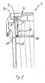
- Fig. 6 is a sectional view taken along the line A - A in Fig. 5 ,
- the cover 4 in this case has a downwardly open groove 9, in the circumferential direction, a seal 10 extends.
- the groove 9 is formed by two downwardly directed webs 9 ', 9 "The outer web 9' has a length such that it securely engages over the upwardly protruding edge of the container 2, but at the same time to the upwardly directed outer edge of the container 2 is also spaced in the closed state of the lid 4.
- the inner web 9 is shown in the Extended design and forms the projecting into the container 2 skirt 8. In this way, contamination of the edge region is reliably prevented
- the skirt 8 is formed thin, that is, that it has a thickness of about 2-10 mm.
- Fig. 7 shows the lid assembly 1 in a side view.
- the circumferentially extending groove 9 is cambered in this embodiment at the respective longitudinal sides.
- the camber preferably has a height of 2-4 mm. In this way, a particularly good seal is achieved because the running in the groove 9 seal 10 is pressed firmly against the upstanding edge of the container 2.
- Fig. 8 shows a sectional view of the lid assembly 1 according to another embodiment.
- the characteristics are essentially the same as those of the Fig. 6
- the webs 9 ', 9 "of the groove 9 are the same length
- the skirt 8 is arranged as an additional element in the interior of the lid 4 and spaced from the inner web 9".
- a circumferentially extending seal 12 preferably a rubber seal, is provided for sealing between the skirt 8 and the inner wall of the container 2.
- Such a seal can be plugged with a Einstecknut on the edge of the skirt and press with a laterally molded thereto sealing bead against the container wall.
- This front skirt portion may also be elastically movable and provided at the corners with a slot 8 '.
- this skirt part can be manually pressed in the Y-direction when opening the lid 4 and a secure concern in the closed state at the front inner wall of the container 2 can be ensured due to its elasticity.
- FIG. 9 how out Fig. 9 can be seen, the features as in connection with the embodiments of a lid in the Fig. 1 to 8 are described with particular advantage in a lid for a ball bottom container 20 used.
- a ball bottom container 20 is in an excellent manner for the absorption of hot fluids, since a strength of the container is ensured even with hot content materials due to the special structure that arises as a result of the combination square container top with ball bottom. This strength is further increased by the tension of the lid in the opening, so that a bulging of wall areas in equipped with lids globe bottom containers.
Landscapes
- Engineering & Computer Science (AREA)
- Mechanical Engineering (AREA)
- Closures For Containers (AREA)
Description
Die Erfindung betrifft eine Deckelanordnung für einen Behälter für Flüssigkeiten, der eine nach unten gerichtete bereichweise schräge Kante aufweist, bereichsweise gemäß dem Oberbegriff des Anspruchs 1.The invention relates to a lid arrangement for a container for liquids, which has a downwardly directed areawise oblique edge, in regions according to the preamble of claim 1.
Aus der
In der
Aus dem Stand der Technik ist weiterhin bei Werkzeugkisten oder Ordnungstonnen bekannt, an Deckelanordnungen Befestigungsklammern vorzusehen, die durch Bolzen gehalten sind. Zur Aufnahme der Bolzen sind an der Deckelanordnung gewöhnlich Halterungen vorgesehen. Die Befestigungsklammern sind somit um die Achse des Bolzens drehbar. Auch ist bekannt, an Befestigungsklammern als Ersatz für einen Bolzen seitliche Vorsprünge vorzusehen, die in entsprechende Aufnahmen an der Deckelanordnung eingreifen. Die Befestigungsklammern lassen sich dann um die seitlichen Vorsprünge drehen. Nachteilig an dem bekannten Stand der Technik ist, dass zur Befestigung oder zum Lösen der Deckelanordnung an bzw. von einem Behälter es notwendig ist, jede einzelne Befestigungsklammer um den Bolzen bzw. die Vorsprünge zu drehen und in Eingriff zu bringen. Auch ist insbesondere bei Tonnen mit den beschriebenen Befestigungsklammern nachteilig, dass diese über den gesamten Umfang in gleichmäßigen Abständen verteilt angeordnet sind, so dass ein erheblicher Arbeitsaufwand besteht, bis sämtliche Befestigungsklammern geschlossen sind.From the state of the art is still known in tool boxes or order tons to provide cover assemblies mounting brackets, which are held by bolts. To accommodate the bolts usually brackets are provided on the cover assembly. The mounting brackets are thus rotatable about the axis of the bolt. It is also known to provide lateral projections on mounting brackets as a replacement for a bolt, which engage in corresponding receptacles on the cover assembly. The mounting brackets can then rotate around the lateral projections. A disadvantage of the known prior art is that for attachment or for releasing the lid assembly to or from a container, it is necessary to rotate and engage each individual mounting bracket to the bolt or the projections. It is also disadvantageous in particular with tons with the described fastening clips that they are distributed over the entire circumference at regular intervals, so that a considerable amount of work is required until all the fastening clips are closed.
Ausgehend von dem Stand der Technik
Es wird eine Deckelanordnung für einen Behälter für Flüssigkeiten, wobei der Behälter eine nach unten gerichtete bereichsweise schräge Kante aufweist,
- mit einem Deckel, der mittels Scharnierarmen, die sich zu einer an dem Behälter angeordneten Halteeinrichtung erstrecken, an dieser Halteeinrich-tung am Behälter drehbar gehalten ist, und
- mit mindestens zwei Befestigungskiammern zum Befestigen des Deckels an dem Behälter, wobei zwei Befestigungsklammern seitlich an zwei gegenüberliegenden Deckelseiten angeordnet sind vorgeschlagen, wobei die Aufgabe dadurch gelöst wird, dass die zwei Befestigungsklammern einstückig an dem Deckel im Vorderbereich ausgebildet sind, sich aus der Deckelebene in Richtung des Behälters erstrecken und ein hakenförmiges freies Ende aufweisen, wobei
- with a lid, which by means of hinge arms, which extend to a holding device arranged on the container, at this Halteeinrich-device is rotatably supported on the container, and
- with at least two mounting clamps for attaching the lid to the container, wherein two mounting brackets are arranged laterally on two opposite sides of the cover proposed, the object is achieved in that the two mounting brackets are integrally formed on the cover in the front region, from the lid plane in the direction extend the container and have a hook-shaped free end, wherein
Die vorliegende Deckelanordnung ist insbesondere bei einer Verwendung an Tonnen günstig, die zur Entsorgung von Altflüssigkeiten, unter anderem auch Fetten oder Ölen, verwendet werden können. Dabei ist es vorteilhaft, dass der Deckel zwei Befestigungsklammern Im Vorderbereich des Deckels aufweist, die einstückig an den Deckel ausgebildet sind. Durch die einstückige Bauweise ist es für den Verwender der Deckelanordnung der Erfindung möglich, ohne zusätzliche Maßnahmen den Deckel durch ein simples nach unten Drücken zu schließen. Die einstückig an dem Deckel ausgebildeten Befestigungsklammern sind auch in einem Handgriff wieder zu lösen. In einer bevorzugten Ausführung ist die Deckelanordnung aus Kunststoff, beispielsweise im Spritzgussverfahren hergestellt, so dass die daran ausgebildeten Befestigungsklammern mit angespritzt sein können.The present lid assembly is particularly beneficial when used on tons that can be used to dispose of waste liquids, including fats or oils. It is advantageous that the lid has two mounting brackets in the front region of the lid, which are integrally formed on the lid. Due to the one-piece design, it is possible for the user of the lid assembly of the invention to close without additional measures the lid by a simple downward pressing. The integrally formed on the cover mounting brackets are also in a handle to solve again. In a preferred embodiment, the lid assembly is made of plastic, for example by injection molding, so that the mounting brackets formed thereon are molded on could be.
Weiterhin ist günstig, dass die Deckelanordnung der Erfindung auf bestehende, genormte Behälter, wie Mülltonnen, aufgesetzt werden kann. Mülltonnen sind nach der Norm EN 840 hergestellt, so dass die Deckelanordnung der Erfindung auf sämtliche derartige Tonnen anwendbar ist Vorzugsweise erstrecken sich die zwei seitlich angeordnete Befestigungsklammern von dem Deckel über einen oberen Umfangsrand des Behälters nach unten (in
Die Befestigungsklammern sind elastisch nach außen zu verbiegen und schnappen bei einer geschlossenen Stellung des Deckels mit ihren hakenförmigen Enden hinter der Kante in einer Schließstellung ein. Zum Schließen des Deckels ist es also lediglich nötig, den Deckel nach unten zu drücken, bis die Befestigungsklammern einrasten. Zum Öffnen des Deckels werden die Befestigungsklammern mit Handkraft nach außen gedrückt und gleichzeitig nach oben bewegt, so dass die einrastende Verbindung der Befestigungsklammern am Umfangsrand der Tonne gelöst ist. Aufgrund der Elastizität der Befestigungsklammern kann die Schließstellung beliebig oft wiederholt werden.The mounting brackets are elastically bend outward and snap in a closed position of the lid with their hooked ends behind the edge in a closed position. To close the lid so it is only necessary to push the lid down until the mounting brackets engage. To open the lid, the mounting brackets are pushed outward with hand force and simultaneously moved upward, so that the latching connection of the mounting brackets is released at the peripheral edge of the barrel. Due to the elasticity of the mounting brackets, the closed position can be repeated as often as desired.
Auch ist es günstig, dass an der Deckelanordnung mindestens ein Befestigungsarm vorgesehen ist, der sich über eine vorbestimmte Länge über die Oberfläche des Deckels erstreckt und sich gleichzeitig an der Halteeinrichtung des Behälters abstützt bzw. daran geführt wird. Der Befestigungsarm kann einstückig mit der Deckelanordnung ausgebildet oder als zusätzliches Teil im Nachhinein angebracht werden. Durch den mindestens einen Befestigungsarm ist eine zusätzliche Absicherung gegen ein ungewolltes Öffnen des Deckels, insbesondere bei Belastungsspitzen durch gegen den Deckel schwappende Flüssigkeit gewährleistet.It is also advantageous that at least one fastening arm is provided on the cover arrangement, which extends over a predetermined length over the surface of the lid and is simultaneously supported on the holding device of the container or is guided thereon. The attachment arm can be formed integrally with the cover assembly or attached as an additional part in retrospect. By at least one mounting arm is an additional safeguard against accidental opening of the lid, especially at peak loads ensured by sloshing against the lid liquid.
In einer besonderen Ausführung kann die Deckelanordnung der Erfindung zusätzlich eine Schürze aufweisen, die in den Behälter hineinragt. In einer besonderen Ausführung kann die Schürze eine Passform zu der Innenwand des Behälters aufweisen. Die in den Behälter hineinragende Schürze dient insbesondere dazu, dass eine mit großer Wucht gegen die Deckelanordnung prallende Flüssigkeit (beispielsweise bei einem Umfallen des Behälters) nicht vollständig auf die Deckeldichtung wirkt, sondern größtenteils von der sich in Umfangsrichtung entlang der Innenwand des Behälters erstreckenden Schürze absorbiert wird. In einer alternativen Ausführung kann die Schürze von der Innenwand des Behälters leicht beabstandet angeordnet sein. Es ist dann sinnvoll, eine zusätzliche Dichtung zwischen der Innenwand des Behälters und der Schürze vorzusehen. Auch ist es möglich, dass der bezüglich des Behälters nach vorne gerichtete Teil der Schürze kürzer ist, um ein leichteres Öffnen und Schließen des Deckels zu gewährleisten. Alternativ oder zusätzlich kann dieser vordere Schürzenteil auch elastisch beweglich sein, so dass er stets an der Innenwand des Behälters anliegen kann. Hierfür könnte ferner vorgesehen sein, die Ecken der Schürze im Vorderbereich zu schlitzen. Mittels der Schürze weist die Deckelanordnung eine zusätzliche Sicherung gegen ein ungewolltes Öffnen des Deckels und somit den ungewollten Austritt von Flüssigkeit auf, da die Schürze an der Innenwand einen Reibwiderstand erzeugt. Die Dichtheit ist insbesondere bei Transport von Gefahrgütern wie beispielsweise Altöl vorteilhaft.In a particular embodiment, the lid assembly of the invention may additionally have an apron, which projects into the container. In a particular embodiment, the skirt may have a fit to the inner wall of the container. The apron projecting into the container serves, in particular, to prevent a liquid bouncing against the lid assembly with great force (for example when the container falls over) from acting completely on the lid seal, but largely absorbed by the apron extending in the circumferential direction along the inner wall of the container becomes. In an alternative embodiment, the skirt may be slightly spaced from the inner wall of the container. It then makes sense to provide an additional seal between the inner wall of the container and the apron. It is also possible for the part of the skirt facing the container to be shorter in order to ensure easier opening and closing of the lid. Alternatively or additionally, this front skirt part can also be elastically movable, so that it can always rest against the inner wall of the container. For this purpose, it could also be provided to slit the corners of the apron in the front area. By means of the apron, the lid assembly an additional safeguard against accidental opening of the lid and thus the unwanted escape of liquid, since the apron on the inner wall generates a frictional resistance. The tightness is particularly advantageous for the transport of dangerous goods such as waste oil.
Die Deckelanordnung ist ferner über ihren Außenrand gegen einen ungewollten Flüssigkeitsaustritt abgedichtet. Hierzu weist die Deckelanordnung eine nach unten gerichtete, zu einem sich über einen von dem Behälter nach oben erstreckenden Rand komplementäre Nut auf. Zum Sicherstellen der Dichtheit ist innerhalb dieser Nut eine Dichtung, vorzugsweise eine Gummidichtung angeordnet. In einer besonderen Ausgestaltung kann die Nut über ihre Länge unterschiedlich tief ausgebildet sein, so dass die darin angeordnete Dichtung an verschiedenen Stellen unterschiedlich tief in der Nut verläuft. Auf diese Weise wird von dem in die Nut ragenden Rand des Behälters, der eine konstante Höhe aufweist, an verschiedenen Stellen der Dichtung eine unterschiedliche Druckkraft ausgeübt, die zu besonderer Dichtheit über den gesamten Umfang der Deckelanordnung führt. In einer bevorzugten Ausführung kann die Nut an allen vier Selten der Deckelanordnung gleichmäßig bombiert sein. Vorzugsweise kann die Bombage auf jeder Längsseite eine Größe von 2 bis 5 mm aufweisen. In einer günstigen Ausführung kann die Schürze eine Verlängerung des inneren Steges der Nut sein.The lid assembly is also sealed over its outer edge against unwanted liquid leakage. For this purpose, the lid arrangement has a downwardly directed groove which extends over a rim extending upwardly from the container. To ensure the tightness within this groove a seal, preferably a rubber seal is arranged. In a particular embodiment, the groove may be formed differently deep over its length, so that the seal arranged therein at different locations at different depths in the groove. In this way, from the projecting into the groove edge of the container, which has a constant height, at different points of the seal a different pressure force exercised, which leads to special tightness over the entire circumference of the lid assembly. In a preferred embodiment, the groove on all four Rare the lid assembly may be evenly cambered. Preferably, the camber on each longitudinal side may have a size of 2 to 5 mm. In a favorable embodiment, the skirt may be an extension of the inner web of the groove.
Zur Stabilisierung und Versteifung des Deckels ist es besonders günstig, unterseitig an dem Deckel Verstärkungsstreben vorzusehen, die einstückig mit an dem Deckel ausgebildet sein können. Die Verstärkungsstreben können in einem beliebigen Muster, beispielsweise stern- oder kreuzförmig ausgebildet sein.To stabilize and stiffen the lid, it is particularly advantageous to provide reinforcing struts on the underside of the lid, which can be integrally formed with the lid. The reinforcing struts can be formed in any pattern, for example star or cross-shaped.
Besonders vorteilhaft ist die Verwendung der Deckelanordnung auf herkömmliche, genormte Behälter, wie Müllfonnen, so dass keine zusätzlichen Kosten für die Entwicklung neuer Tonnen und Anlagen anfallen.Particularly advantageous is the use of the lid assembly on conventional, standardized containers, such as refuse, so that no additional costs incurred for the development of new tons and equipment.
Weitere Vorteile der Erfindung werden nachstehend gemeinsam mit der Beschreibung eines bevorzugten Ausführungsbeispiels der Erfindung anhand der Figuren näher dargestellt. Die Darstellung in den beigefügten Figuren erfolgt beispielhaft und schematisch. In den Figuren sind jeweils gleiche Teile mit gleichen Bezugszeichen versehen. Ferner sind nur die für das Verständnis der Erfindung wesentlichen Elemente dargestellt. Es zeigen
- Fig. 1
- die Deckelanordnung der Erfindung auf einem Behälter in einer perspektivischen Ansicht;
- Fig. 2
- die Deckelanordnung der Erfindung in einer perspektivischen Ansicht von schräg oben;
- Fig. 3
- die Deckelanordnung der Erfindung in einer perspektivischen Ansicht von schräg unten;
- Fig. 4
- die Deckelanordnung der Erfindung auf einem Behälter in einer Ansicht von oben;
- Fig. 5
- zeigt eine weitere Ausführung der Deckelanordnung der Erfindung in einer Ansicht von oben;
- Fig. 6
- zeigt eine Schnittansicht A - A aus der
Fig. 5 ; - Fig. 7
- zeigt einen Teil einer seitlichen Schnittansicht der Deckelanordnung;
- Fig. 8
- zeigt eine weitere Ausführungsform eines Teils der Deckelanordnung in einer Schnittansicht und
- Fig. 9
- zeigt ein Kugelbodenmüllgefäß oder -behälter mit erfindungsgemäßer Deckelanordnung.
- Fig. 1
- the lid assembly of the invention on a container in a perspective view;
- Fig. 2
- the lid assembly of the invention in a perspective view obliquely from above;
- Fig. 3
- the lid assembly of the invention in a perspective view obliquely from below;
- Fig. 4
- the lid assembly of the invention on a container in one View from above;
- Fig. 5
- shows a further embodiment of the lid assembly of the invention in a view from above;
- Fig. 6
- shows a sectional view A - A from the
Fig. 5 ; - Fig. 7
- shows a part of a side sectional view of the lid assembly;
- Fig. 8
- shows a further embodiment of a portion of the lid assembly in a sectional view and
- Fig. 9
- shows a Kugelbodenmüllgefäß or container with inventive lid assembly.
In
Die einstückig an dem Deckel 4 der Deckelanordnung 1 ausgebildeten Befestigungsklammern 3 erstrecken sich von dem Deckel 4 zunächst in X-Richtung nach außen, bilden eine Bogenform um den Rand der Deckelanordnung 1 und erstrecken sich weiter im wesentlichen senkrecht in Z-Richtung nach unten, um über ihre Länge sowohl die Deckelanordnung 1 als auch den oberen Rand des Behälters 2 zu übergreifen. An ihrem freien Ende 3' weisen die Befestigungsklammern 3 eine Hakenform (vgl.
Zusätzlich ist bei der Deckelanordnung 4 mindestens ein Befestigungsarm 7 vorgesehen, der sich über eine vorbestimmte Länge des hinteren Teils der Deckelanordnung 1 in Y-Richtung erstreckt. Der Befestigungsarm 7 ist einstückig mit dem Deckel 4 ausgebildet und rückseitig an der als Stange ausgebildeten Halteeinrichtung 6 abgestützt und geführt. Hierdurch ist eine zusätzliche Sicherung der Schließstellung der Deckelanordnung 1 gewährleistet. Gleichzeitig kann bei Belastungsspitzen auf die Deckelanordnung 1 die auftretende Kraft auch auf den Befestigungsarm 7 und somit mittelbar auf die Halteeinrichtung 6 verteilt werden.In addition, at least one
In
In
Es wird ausdrücklich darauf hingewiesen, dass alle verschiedenen Merkmalselemente der einzeinen Ausführungsbeispiele beliebig miteinander kombinierbar sind, soweit wie dies technisch möglich ist und kein Widerspruch besteht. So ist es z. B. möglich, auch bei einer an der Innenwand des Behälters anliegenden Schürze gemäß
Wie aus
Claims (20)
- Lid assembly for a container (2) for liquids, the container (2) comprising a downward-facing edge which Is angled In regions,- having a lid (4) which, by means of hinge arms (5) which extend to a holding means (6) arranged on the container (2), is rotatably held on the container (2) on said holding means (6), and- having at least two fastening clamps (3) for fastening the lid (4) to the container (2), two fastening clamps (3) being arranged laterally on two opposite sides of the lid,characterised In that the two fastening clamps are formed in one piece on the lid in the front region, extend from the plane of the lid towards the container (2) and comprise a hook-shaped free end (3'),
each hook-shaped free end (3') of the fastening clamps (3) comprising a bevel, which engages behind each downward-facing, angled edge on the container (2). - Lid assembly according to claim 1, characterised in that the two fastening clamps (3) can spring back resiliently.
- Lid assembly according to either claim 1 or claim 2, characterised in that the two fastening clamps (3) are made of plastics material.
- Lid assembly according to any of the preceding claims, characterised In that the two fastening clamps (3) comprise lateral reinforcements.
- Lid assembly according to claim 4, characterised In that at least one fastening arm (7) is provided which Is arranged on the lid (4), acts on the holding means (6) and extends over the lid (4) at a predetermined length.
- Lid assembly according to the preceding claim, characterised in that the at least one fastening arm (7) is formed In one piece together with the lid (4).
- Lid assembly according to claim 1, characterised In that a skirt (8) is provided which extends downwards from the lid assembly (1) and projects into the container (2).
- Lid assembly according to the preceding claim, characterised in that the skirt (8) is 10 to 150 mm long.
- Lid assembly according to either claim 7 or claim 8, characterised in that the skirt (8) is formed so as to fit to the inner wall of the container (2).
- Lid assembly according to any of claims 7 to 9, characterised In that an additional seal (12) is provided between the Inner wall of the container (2) and the skirt (8), the seal (12) extending in the circumferential direction.
- Lid assembly according to claim 10, characterised in that the seal (12) having an insertion groove is mounted on the edge of the skirt (8) and is pressed against the container wall by a sealing bead formed laterally on the edge of the skirt.
- Lid assembly according to any of claims 7 to 11, characterised in that the skirt (8) is- shorter along the front longitudinal side of the lid assembly (1) and/or- resiliently pivotable and/or- provided with slits (8') on at least two of the corners of the container.
- Lid assembly according to any of claims 7 to 12, characterised in that the skirt (8) generates frictional resistance on the inner wall of the container (2).
- Lid assembly according to any of the preceding claims, characterised In that the lid assembly (1) comprises a groove which faces downwards and is complementary to an edge which extends upwards from the container (2).
- Lid assembly according to any of claims 7 to 12, in conjunction with claim 14, characterised in that the skirt (8) Is an extension of a web (9") which forms part of the groove (9).
- Lid assembly according to any of claims 7 to 13, In conjunction with either claim 14 or claim 15, characterised in that the skirt (8) Is spaced inwards from the groove (9).
- Lid assembly according to any of claims 14 to 16, characterised in that the downward-facing groove (9) has different depths.
- Lid assembly according to any of claims 14 to 17, characterised in that a seal (10) Is arranged in the downward-facing groove (9).
- Lid assembly according to any of the preceding claims, characterised in that the lid (4) comprises reinforcement struts (11) on the underside thereof.
- Lid assembly according to any of the preceding claims, characterised in that the lid (4) comprises at least one reinforcement rib (4') on the top thereof.
Priority Applications (2)
| Application Number | Priority Date | Filing Date | Title |
|---|---|---|---|
| SI200830901T SI2036838T1 (en) | 2007-09-14 | 2008-04-23 | Lid assembly for a fluid container |
| PL08007860T PL2036838T3 (en) | 2007-09-14 | 2008-04-23 | Lid assembly for a fluid container |
Applications Claiming Priority (1)
| Application Number | Priority Date | Filing Date | Title |
|---|---|---|---|
| DE202007012923U DE202007012923U1 (en) | 2007-09-11 | 2007-09-14 | Lid arrangement for a liquid container |
Publications (2)
| Publication Number | Publication Date |
|---|---|
| EP2036838A1 EP2036838A1 (en) | 2009-03-18 |
| EP2036838B1 true EP2036838B1 (en) | 2012-12-05 |
Family
ID=39884556
Family Applications (1)
| Application Number | Title | Priority Date | Filing Date |
|---|---|---|---|
| EP08007860A Active EP2036838B1 (en) | 2007-09-14 | 2008-04-23 | Lid assembly for a fluid container |
Country Status (8)
| Country | Link |
|---|---|
| US (1) | US8479949B2 (en) |
| EP (1) | EP2036838B1 (en) |
| KR (1) | KR20090027178A (en) |
| AU (1) | AU2008212080B8 (en) |
| ES (1) | ES2400820T3 (en) |
| PL (1) | PL2036838T3 (en) |
| RU (1) | RU2491218C2 (en) |
| SI (1) | SI2036838T1 (en) |
Families Citing this family (25)
| Publication number | Priority date | Publication date | Assignee | Title |
|---|---|---|---|---|
| KR100925547B1 (en) * | 2009-04-06 | 2009-11-06 | (주)오토코리아 | Dustbin having damper |
| KR100925542B1 (en) * | 2009-04-06 | 2009-11-06 | (주)오토코리아 | Dustbin having damper |
| KR101336827B1 (en) * | 2012-07-24 | 2013-12-04 | 엔피씨(주) | Food garbage basket |
| CA2838382A1 (en) | 2013-01-09 | 2014-07-09 | Speed Eco Products and Systems Ltd. | Container lid latch |
| US9726380B2 (en) * | 2013-07-10 | 2017-08-08 | Kenyon International, Inc. | Collapsible grill lid |
| US9258943B1 (en) * | 2013-08-06 | 2016-02-16 | John W. Ruger | Plant extraction assembly |
| US11376152B2 (en) | 2014-03-19 | 2022-07-05 | Purewick Corporation | Apparatus and methods for receiving discharged urine |
| US11806266B2 (en) | 2014-03-19 | 2023-11-07 | Purewick Corporation | Apparatus and methods for receiving discharged urine |
| US9821830B1 (en) * | 2016-05-23 | 2017-11-21 | Janelle Matlock | Covered wheelbarrow system |
| US10973678B2 (en) | 2016-07-27 | 2021-04-13 | Purewick Corporation | Apparatus and methods for receiving discharged urine |
| US10900255B2 (en) | 2016-08-15 | 2021-01-26 | Fath, Inc. | Tamper resistant gravity latch |
| MX2017014522A (en) * | 2016-11-11 | 2018-10-04 | Rehrig Pacific Co | Roll out cart. |
| USD839074S1 (en) | 2017-08-14 | 2019-01-29 | Fath, Inc. | Gravity latch |
| US11944740B2 (en) | 2018-05-01 | 2024-04-02 | Purewick Corporation | Fluid collection devices, related systems, and related methods |
| WO2019212951A1 (en) | 2018-05-01 | 2019-11-07 | Purewick Corporation | Fluid collection devices, systems, and methods |
| WO2019212954A1 (en) | 2018-05-01 | 2019-11-07 | Purewick Corporation | Fluid collection garments |
| US11084514B2 (en) * | 2018-10-16 | 2021-08-10 | Toolspace Pty Ltd | Semipermanent wheelbarrow enclosure |
| DE102019101724A1 (en) * | 2019-01-24 | 2020-07-30 | Sudhaus Gmbh | Waste collection device |
| DE202019104264U1 (en) * | 2019-08-02 | 2020-11-03 | Sudhaus Gmbh | Waste collection device |
| USD967409S1 (en) | 2020-07-15 | 2022-10-18 | Purewick Corporation | Urine collection apparatus cover |
| US11801186B2 (en) | 2020-09-10 | 2023-10-31 | Purewick Corporation | Urine storage container handle and lid accessories |
| AU2022211357A1 (en) | 2021-01-19 | 2023-06-22 | Purewick Corporation | Variable fit fluid collection devices, systems, and methods |
| WO2022182385A1 (en) | 2021-02-26 | 2022-09-01 | Purewick Corporation | Fluid collection devices having a sump between a tube opening and a barrier, and related systems and methods |
| US11938054B2 (en) | 2021-03-10 | 2024-03-26 | Purewick Corporation | Bodily waste and fluid collection with sacral pad |
| USD1027607S1 (en) | 2022-08-17 | 2024-05-21 | Fath, Inc. | Gravity latch |
Family Cites Families (18)
| Publication number | Priority date | Publication date | Assignee | Title |
|---|---|---|---|---|
| US3688942A (en) * | 1970-11-20 | 1972-09-05 | Continental Can Co | Container and closure combination |
| US3759415A (en) * | 1972-06-13 | 1973-09-18 | Nosco Plastics | Pail |
| US3999677A (en) * | 1975-06-30 | 1976-12-28 | Van Dorn Company | Plastic lid for containers |
| IT1204261B (en) * | 1986-01-24 | 1989-03-01 | Olimpio Stocchiero | LID FOR ACCUMULATORS CLOSED BY PRESSURE ON THE CONTAINER |
| US4691840A (en) * | 1986-11-12 | 1987-09-08 | Gott Corporation | Lid locking handle for waste container |
| US5103994A (en) * | 1990-12-28 | 1992-04-14 | Rubbermaid Incorporated | Locking system for a waste receptacle |
| US5230525A (en) * | 1991-06-25 | 1993-07-27 | Rubbermaid Commercial Products Inc. | Step-on waste container |
| US5207345A (en) * | 1992-07-10 | 1993-05-04 | Stewart Gene L | Lid adapter for bucket |
| US5323923A (en) * | 1992-08-17 | 1994-06-28 | Schauer Charles D | Waste container |
| US5385259A (en) * | 1994-01-28 | 1995-01-31 | Safety 1St, Inc. | Diaper pail |
| US5641090A (en) * | 1994-11-14 | 1997-06-24 | Rubbermaid Commercial Products Inc. | Lid for refuse a container |
| US5699929A (en) * | 1996-03-25 | 1997-12-23 | Ouno; Taiichi | Garbage container |
| FR2784364B1 (en) * | 1998-10-13 | 2000-12-15 | Plastic Omnium Cie | BIN FOR THE COLLECTION OF WASTE, EQUIPPED WITH A TRANSPONDER |
| US20030160057A1 (en) * | 2000-07-12 | 2003-08-28 | Wiggo-Arne Johansen | Blocking device for a waste container lid |
| ES1048353Y (en) | 2001-02-15 | 2001-12-01 | Contenur Espana Sl | CONTAINER BUCK FOR SELECTIVE COLLECTION OF LIQUID WASTE. |
| CA2372465A1 (en) * | 2002-02-15 | 2003-08-15 | Norseman Plastics Limited | Refuse container |
| DE20304131U1 (en) | 2003-03-13 | 2003-06-05 | Haefner & Krullmann Gmbh | Bin for collecting of especially domestic waste has sprung locking hook formed or fitted on lid and equipped with protruding locking member which fits under rim or reinforcing rail formed on edge of bin's body |
| DE202007012923U1 (en) * | 2007-09-11 | 2008-03-27 | P. Henkel Gmbh | Lid arrangement for a liquid container |
-
2008
- 2008-04-23 EP EP08007860A patent/EP2036838B1/en active Active
- 2008-04-23 SI SI200830901T patent/SI2036838T1/en unknown
- 2008-04-23 ES ES08007860T patent/ES2400820T3/en active Active
- 2008-04-23 PL PL08007860T patent/PL2036838T3/en unknown
- 2008-09-09 AU AU2008212080A patent/AU2008212080B8/en active Active
- 2008-09-09 US US12/283,065 patent/US8479949B2/en active Active
- 2008-09-10 RU RU2008136535/12A patent/RU2491218C2/en active
- 2008-09-11 KR KR1020080089882A patent/KR20090027178A/en not_active Application Discontinuation
Also Published As
| Publication number | Publication date |
|---|---|
| AU2008212080B2 (en) | 2013-11-07 |
| PL2036838T3 (en) | 2013-05-31 |
| US8479949B2 (en) | 2013-07-09 |
| AU2008212080B8 (en) | 2014-02-27 |
| AU2008212080A8 (en) | 2014-02-27 |
| US20090134164A1 (en) | 2009-05-28 |
| SI2036838T1 (en) | 2013-04-30 |
| EP2036838A1 (en) | 2009-03-18 |
| KR20090027178A (en) | 2009-03-16 |
| ES2400820T3 (en) | 2013-04-12 |
| RU2491218C2 (en) | 2013-08-27 |
| AU2008212080A1 (en) | 2009-03-26 |
| RU2008136535A (en) | 2010-03-20 |
Similar Documents
| Publication | Publication Date | Title |
|---|---|---|
| EP2036838B1 (en) | Lid assembly for a fluid container | |
| AT401767B (en) | WASTE BIN | |
| AT507950B1 (en) | COVER OF A CONTAINER | |
| DE4143145A1 (en) | LOCKING SYSTEM FOR A WASTE BIN | |
| EP0881161B1 (en) | Transport and storage container for liquids | |
| EP1343703A1 (en) | Pallet container | |
| EP1533244B1 (en) | Container with pivotally mounted cover | |
| DE202007012923U1 (en) | Lid arrangement for a liquid container | |
| EP3552983B1 (en) | Container with locking ring for securing a lid for transport | |
| WO2021156144A1 (en) | Container for transporting and storing liquids, said container comprising a fixing ring | |
| WO2017085171A1 (en) | Container made of plastic | |
| DE202009012302U1 (en) | Container with flanged edges | |
| DE2725215A1 (en) | CLOSURE | |
| CH690272A5 (en) | Application part for domestic sweepings container in which sweepings bag can be inserted comprises ring body with outer shape corresponding to opening cross-section of container and is provided with retention devices | |
| EP0633204B1 (en) | Refuse container | |
| EP3655340A1 (en) | Container | |
| WO1988000915A1 (en) | Collection tank for reusable product | |
| DE2254600C3 (en) | Closing device for cans or similar containers made of metal | |
| DE202020106218U1 (en) | Circlip to secure a lid, lid and container during transport | |
| DE3104604A1 (en) | Can closure | |
| DE4439821C2 (en) | Motor vehicle door lock | |
| WO1994005558A1 (en) | Sealing cap for a safety closure | |
| DE4422936A1 (en) | container | |
| DE102009032929B4 (en) | Container with a manhole | |
| DE202017100341U1 (en) | container |
Legal Events
| Date | Code | Title | Description |
|---|---|---|---|
| PUAI | Public reference made under article 153(3) epc to a published international application that has entered the european phase |
Free format text: ORIGINAL CODE: 0009012 |
|
| 17P | Request for examination filed |
Effective date: 20080710 |
|
| AK | Designated contracting states |
Kind code of ref document: A1 Designated state(s): AT BE BG CH CY CZ DE DK EE ES FI FR GB GR HR HU IE IS IT LI LT LU LV MC MT NL NO PL PT RO SE SI SK TR |
|
| AX | Request for extension of the european patent |
Extension state: AL BA MK RS |
|
| AKX | Designation fees paid |
Designated state(s): AT BE BG CH CY CZ DE DK EE ES FI FR GB GR HR HU IE IS IT LI LT LU LV MC MT NL NO PL PT RO SE SI SK TR |
|
| 17Q | First examination report despatched |
Effective date: 20091216 |
|
| GRAP | Despatch of communication of intention to grant a patent |
Free format text: ORIGINAL CODE: EPIDOSNIGR1 |
|
| GRAS | Grant fee paid |
Free format text: ORIGINAL CODE: EPIDOSNIGR3 |
|
| GRAA | (expected) grant |
Free format text: ORIGINAL CODE: 0009210 |
|
| AK | Designated contracting states |
Kind code of ref document: B1 Designated state(s): AT BE BG CH CY CZ DE DK EE ES FI FR GB GR HR HU IE IS IT LI LT LU LV MC MT NL NO PL PT RO SE SI SK TR |
|
| REG | Reference to a national code |
Ref country code: GB Ref legal event code: FG4D Free format text: NOT ENGLISH |
|
| REG | Reference to a national code |
Ref country code: CH Ref legal event code: EP |
|
| REG | Reference to a national code |
Ref country code: AT Ref legal event code: REF Ref document number: 587161 Country of ref document: AT Kind code of ref document: T Effective date: 20121215 |
|
| REG | Reference to a national code |
Ref country code: IE Ref legal event code: FG4D Free format text: LANGUAGE OF EP DOCUMENT: GERMAN |
|
| REG | Reference to a national code |
Ref country code: DE Ref legal event code: R096 Ref document number: 502008008805 Country of ref document: DE Effective date: 20130131 |
|
| REG | Reference to a national code |
Ref country code: SE Ref legal event code: TRGR |
|
| REG | Reference to a national code |
Ref country code: ES Ref legal event code: FG2A Ref document number: 2400820 Country of ref document: ES Kind code of ref document: T3 Effective date: 20130412 |
|
| PG25 | Lapsed in a contracting state [announced via postgrant information from national office to epo] |
Ref country code: FI Free format text: LAPSE BECAUSE OF FAILURE TO SUBMIT A TRANSLATION OF THE DESCRIPTION OR TO PAY THE FEE WITHIN THE PRESCRIBED TIME-LIMIT Effective date: 20121205 Ref country code: NO Free format text: LAPSE BECAUSE OF FAILURE TO SUBMIT A TRANSLATION OF THE DESCRIPTION OR TO PAY THE FEE WITHIN THE PRESCRIBED TIME-LIMIT Effective date: 20130305 Ref country code: LT Free format text: LAPSE BECAUSE OF FAILURE TO SUBMIT A TRANSLATION OF THE DESCRIPTION OR TO PAY THE FEE WITHIN THE PRESCRIBED TIME-LIMIT Effective date: 20121205 |
|
| REG | Reference to a national code |
Ref country code: NL Ref legal event code: VDEP Effective date: 20121205 |
|
| REG | Reference to a national code |
Ref country code: SK Ref legal event code: T3 Ref document number: E 13535 Country of ref document: SK |
|
| REG | Reference to a national code |
Ref country code: LT Ref legal event code: MG4D |
|
| PG25 | Lapsed in a contracting state [announced via postgrant information from national office to epo] |
Ref country code: LV Free format text: LAPSE BECAUSE OF FAILURE TO SUBMIT A TRANSLATION OF THE DESCRIPTION OR TO PAY THE FEE WITHIN THE PRESCRIBED TIME-LIMIT Effective date: 20121205 Ref country code: GR Free format text: LAPSE BECAUSE OF FAILURE TO SUBMIT A TRANSLATION OF THE DESCRIPTION OR TO PAY THE FEE WITHIN THE PRESCRIBED TIME-LIMIT Effective date: 20130306 |
|
| REG | Reference to a national code |
Ref country code: PL Ref legal event code: T3 |
|
| PG25 | Lapsed in a contracting state [announced via postgrant information from national office to epo] |
Ref country code: IS Free format text: LAPSE BECAUSE OF FAILURE TO SUBMIT A TRANSLATION OF THE DESCRIPTION OR TO PAY THE FEE WITHIN THE PRESCRIBED TIME-LIMIT Effective date: 20130405 Ref country code: BG Free format text: LAPSE BECAUSE OF FAILURE TO SUBMIT A TRANSLATION OF THE DESCRIPTION OR TO PAY THE FEE WITHIN THE PRESCRIBED TIME-LIMIT Effective date: 20130305 Ref country code: EE Free format text: LAPSE BECAUSE OF FAILURE TO SUBMIT A TRANSLATION OF THE DESCRIPTION OR TO PAY THE FEE WITHIN THE PRESCRIBED TIME-LIMIT Effective date: 20121205 |
|
| PG25 | Lapsed in a contracting state [announced via postgrant information from national office to epo] |
Ref country code: PT Free format text: LAPSE BECAUSE OF FAILURE TO SUBMIT A TRANSLATION OF THE DESCRIPTION OR TO PAY THE FEE WITHIN THE PRESCRIBED TIME-LIMIT Effective date: 20130405 Ref country code: RO Free format text: LAPSE BECAUSE OF FAILURE TO SUBMIT A TRANSLATION OF THE DESCRIPTION OR TO PAY THE FEE WITHIN THE PRESCRIBED TIME-LIMIT Effective date: 20121205 |
|
| PLBE | No opposition filed within time limit |
Free format text: ORIGINAL CODE: 0009261 |
|
| STAA | Information on the status of an ep patent application or granted ep patent |
Free format text: STATUS: NO OPPOSITION FILED WITHIN TIME LIMIT |
|
| PG25 | Lapsed in a contracting state [announced via postgrant information from national office to epo] |
Ref country code: DK Free format text: LAPSE BECAUSE OF FAILURE TO SUBMIT A TRANSLATION OF THE DESCRIPTION OR TO PAY THE FEE WITHIN THE PRESCRIBED TIME-LIMIT Effective date: 20121205 |
|
| 26N | No opposition filed |
Effective date: 20130906 |
|
| PG25 | Lapsed in a contracting state [announced via postgrant information from national office to epo] |
Ref country code: CY Free format text: LAPSE BECAUSE OF FAILURE TO SUBMIT A TRANSLATION OF THE DESCRIPTION OR TO PAY THE FEE WITHIN THE PRESCRIBED TIME-LIMIT Effective date: 20121205 Ref country code: HR Free format text: LAPSE BECAUSE OF FAILURE TO SUBMIT A TRANSLATION OF THE DESCRIPTION OR TO PAY THE FEE WITHIN THE PRESCRIBED TIME-LIMIT Effective date: 20121205 Ref country code: MC Free format text: LAPSE BECAUSE OF FAILURE TO SUBMIT A TRANSLATION OF THE DESCRIPTION OR TO PAY THE FEE WITHIN THE PRESCRIBED TIME-LIMIT Effective date: 20121205 |
|
| REG | Reference to a national code |
Ref country code: DE Ref legal event code: R097 Ref document number: 502008008805 Country of ref document: DE Effective date: 20130906 |
|
| REG | Reference to a national code |
Ref country code: NL Ref legal event code: RD1H Effective date: 20140513 |
|
| REG | Reference to a national code |
Ref country code: NL Ref legal event code: RDX Effective date: 20140617 Ref country code: NL Ref legal event code: RD1H Effective date: 20140513 |
|
| REG | Reference to a national code |
Ref country code: NL Ref legal event code: BK Free format text: TEN ONTERECHTE VERVALLENOP 2012.12.05 PUBLIKATIE I.E. 2013/18UITGEGEVEN 2013.05.01 |
|
| PG25 | Lapsed in a contracting state [announced via postgrant information from national office to epo] |
Ref country code: MT Free format text: LAPSE BECAUSE OF FAILURE TO SUBMIT A TRANSLATION OF THE DESCRIPTION OR TO PAY THE FEE WITHIN THE PRESCRIBED TIME-LIMIT Effective date: 20121205 |
|
| PG25 | Lapsed in a contracting state [announced via postgrant information from national office to epo] |
Ref country code: TR Free format text: LAPSE BECAUSE OF FAILURE TO SUBMIT A TRANSLATION OF THE DESCRIPTION OR TO PAY THE FEE WITHIN THE PRESCRIBED TIME-LIMIT Effective date: 20121205 |
|
| PG25 | Lapsed in a contracting state [announced via postgrant information from national office to epo] |
Ref country code: LU Free format text: LAPSE BECAUSE OF NON-PAYMENT OF DUE FEES Effective date: 20130423 Ref country code: HU Free format text: LAPSE BECAUSE OF FAILURE TO SUBMIT A TRANSLATION OF THE DESCRIPTION OR TO PAY THE FEE WITHIN THE PRESCRIBED TIME-LIMIT; INVALID AB INITIO Effective date: 20080423 |
|
| REG | Reference to a national code |
Ref country code: NL Ref legal event code: RD2H Effective date: 20140704 |
|
| REG | Reference to a national code |
Ref country code: FR Ref legal event code: PLFP Year of fee payment: 9 |
|
| REG | Reference to a national code |
Ref country code: FR Ref legal event code: PLFP Year of fee payment: 10 |
|
| REG | Reference to a national code |
Ref country code: FR Ref legal event code: PLFP Year of fee payment: 11 |
|
| PGFP | Annual fee paid to national office [announced via postgrant information from national office to epo] |
Ref country code: PL Payment date: 20230321 Year of fee payment: 16 |
|
| PGFP | Annual fee paid to national office [announced via postgrant information from national office to epo] |
Ref country code: IT Payment date: 20230426 Year of fee payment: 16 Ref country code: IE Payment date: 20230419 Year of fee payment: 16 Ref country code: FR Payment date: 20230420 Year of fee payment: 16 Ref country code: ES Payment date: 20230627 Year of fee payment: 16 Ref country code: DE Payment date: 20230626 Year of fee payment: 16 Ref country code: CZ Payment date: 20230414 Year of fee payment: 16 Ref country code: CH Payment date: 20230502 Year of fee payment: 16 |
|
| PGFP | Annual fee paid to national office [announced via postgrant information from national office to epo] |
Ref country code: SK Payment date: 20230418 Year of fee payment: 16 Ref country code: SI Payment date: 20230413 Year of fee payment: 16 Ref country code: SE Payment date: 20230420 Year of fee payment: 16 Ref country code: AT Payment date: 20230420 Year of fee payment: 16 |
|
| PGFP | Annual fee paid to national office [announced via postgrant information from national office to epo] |
Ref country code: BE Payment date: 20230419 Year of fee payment: 16 |
|
| PGFP | Annual fee paid to national office [announced via postgrant information from national office to epo] |
Ref country code: GB Payment date: 20230419 Year of fee payment: 16 |
|
| PGFP | Annual fee paid to national office [announced via postgrant information from national office to epo] |
Ref country code: NL Payment date: 20240418 Year of fee payment: 17 |