EP2036201B1 - Filtereinheit und verfahren zur erzeugung von subbandfilter-impulsreaktionen - Google Patents
Filtereinheit und verfahren zur erzeugung von subbandfilter-impulsreaktionen Download PDFInfo
- Publication number
- EP2036201B1 EP2036201B1 EP07765029.9A EP07765029A EP2036201B1 EP 2036201 B1 EP2036201 B1 EP 2036201B1 EP 07765029 A EP07765029 A EP 07765029A EP 2036201 B1 EP2036201 B1 EP 2036201B1
- Authority
- EP
- European Patent Office
- Prior art keywords
- filter
- impulse response
- filter impulse
- subband
- value
- Prior art date
- Legal status (The legal status is an assumption and is not a legal conclusion. Google has not performed a legal analysis and makes no representation as to the accuracy of the status listed.)
- Active
Links
- 230000004044 response Effects 0.000 title claims description 479
- 238000000034 method Methods 0.000 title claims description 33
- 238000011156 evaluation Methods 0.000 claims description 87
- 238000003860 storage Methods 0.000 claims description 28
- 238000005303 weighing Methods 0.000 claims description 24
- 238000012546 transfer Methods 0.000 claims description 14
- 230000014509 gene expression Effects 0.000 claims description 11
- 238000012545 processing Methods 0.000 claims description 7
- 238000004590 computer program Methods 0.000 claims description 6
- 238000004458 analytical method Methods 0.000 description 45
- 230000002087 whitening effect Effects 0.000 description 41
- 238000001914 filtration Methods 0.000 description 37
- 230000006870 function Effects 0.000 description 26
- 230000015572 biosynthetic process Effects 0.000 description 23
- 238000003786 synthesis reaction Methods 0.000 description 23
- 230000003595 spectral effect Effects 0.000 description 21
- 230000009467 reduction Effects 0.000 description 12
- 230000006835 compression Effects 0.000 description 9
- 238000007906 compression Methods 0.000 description 9
- 239000011159 matrix material Substances 0.000 description 7
- 230000001934 delay Effects 0.000 description 6
- 230000002829 reductive effect Effects 0.000 description 6
- 238000013461 design Methods 0.000 description 5
- 230000000694 effects Effects 0.000 description 5
- 238000004519 manufacturing process Methods 0.000 description 5
- 230000015654 memory Effects 0.000 description 5
- 230000036961 partial effect Effects 0.000 description 5
- 238000005070 sampling Methods 0.000 description 5
- 238000004364 calculation method Methods 0.000 description 4
- 238000009826 distribution Methods 0.000 description 4
- 230000003993 interaction Effects 0.000 description 4
- 230000004048 modification Effects 0.000 description 4
- 238000012986 modification Methods 0.000 description 4
- 230000009466 transformation Effects 0.000 description 4
- 238000011161 development Methods 0.000 description 3
- 230000018109 developmental process Effects 0.000 description 3
- 239000000203 mixture Substances 0.000 description 3
- 238000010606 normalization Methods 0.000 description 3
- 230000005236 sound signal Effects 0.000 description 3
- 238000000844 transformation Methods 0.000 description 3
- 230000008901 benefit Effects 0.000 description 2
- 230000008859 change Effects 0.000 description 2
- 238000006243 chemical reaction Methods 0.000 description 2
- 230000002349 favourable effect Effects 0.000 description 2
- 230000000670 limiting effect Effects 0.000 description 2
- 230000000873 masking effect Effects 0.000 description 2
- 230000000717 retained effect Effects 0.000 description 2
- DNTFEAHNXKUSKQ-RFZPGFLSSA-N (1r,2r)-2-aminocyclopentane-1-sulfonic acid Chemical compound N[C@@H]1CCC[C@H]1S(O)(=O)=O DNTFEAHNXKUSKQ-RFZPGFLSSA-N 0.000 description 1
- 230000006978 adaptation Effects 0.000 description 1
- 230000004075 alteration Effects 0.000 description 1
- 230000006399 behavior Effects 0.000 description 1
- 229910002056 binary alloy Inorganic materials 0.000 description 1
- 239000011449 brick Substances 0.000 description 1
- 238000004422 calculation algorithm Methods 0.000 description 1
- 230000021615 conjugation Effects 0.000 description 1
- 230000008878 coupling Effects 0.000 description 1
- 238000010168 coupling process Methods 0.000 description 1
- 238000005859 coupling reaction Methods 0.000 description 1
- 238000009795 derivation Methods 0.000 description 1
- 238000010586 diagram Methods 0.000 description 1
- 238000005265 energy consumption Methods 0.000 description 1
- 230000005284 excitation Effects 0.000 description 1
- 239000000284 extract Substances 0.000 description 1
- 238000000605 extraction Methods 0.000 description 1
- 238000003780 insertion Methods 0.000 description 1
- 230000037431 insertion Effects 0.000 description 1
- 238000013507 mapping Methods 0.000 description 1
- 238000005457 optimization Methods 0.000 description 1
- 230000008447 perception Effects 0.000 description 1
- 238000012805 post-processing Methods 0.000 description 1
- 230000008569 process Effects 0.000 description 1
- 230000006798 recombination Effects 0.000 description 1
- 238000005215 recombination Methods 0.000 description 1
- 238000011946 reduction process Methods 0.000 description 1
- 230000001131 transforming effect Effects 0.000 description 1
- 230000007704 transition Effects 0.000 description 1
Images


Classifications
-
- H—ELECTRICITY
- H03—ELECTRONIC CIRCUITRY
- H03H—IMPEDANCE NETWORKS, e.g. RESONANT CIRCUITS; RESONATORS
- H03H17/00—Networks using digital techniques
- H03H17/02—Frequency selective networks
- H03H17/0248—Filters characterised by a particular frequency response or filtering method
- H03H17/0264—Filter sets with mutual related characteristics
- H03H17/0272—Quadrature mirror filters
-
- H—ELECTRICITY
- H03—ELECTRONIC CIRCUITRY
- H03H—IMPEDANCE NETWORKS, e.g. RESONANT CIRCUITS; RESONATORS
- H03H17/00—Networks using digital techniques
- H03H17/02—Frequency selective networks
-
- G—PHYSICS
- G10—MUSICAL INSTRUMENTS; ACOUSTICS
- G10L—SPEECH ANALYSIS TECHNIQUES OR SPEECH SYNTHESIS; SPEECH RECOGNITION; SPEECH OR VOICE PROCESSING TECHNIQUES; SPEECH OR AUDIO CODING OR DECODING
- G10L19/00—Speech or audio signals analysis-synthesis techniques for redundancy reduction, e.g. in vocoders; Coding or decoding of speech or audio signals, using source filter models or psychoacoustic analysis
- G10L19/02—Speech or audio signals analysis-synthesis techniques for redundancy reduction, e.g. in vocoders; Coding or decoding of speech or audio signals, using source filter models or psychoacoustic analysis using spectral analysis, e.g. transform vocoders or subband vocoders
-
- H—ELECTRICITY
- H03—ELECTRONIC CIRCUITRY
- H03H—IMPEDANCE NETWORKS, e.g. RESONANT CIRCUITS; RESONATORS
- H03H17/00—Networks using digital techniques
- H03H17/02—Frequency selective networks
- H03H17/0248—Filters characterised by a particular frequency response or filtering method
- H03H17/0264—Filter sets with mutual related characteristics
- H03H17/0266—Filter banks
-
- H—ELECTRICITY
- H03—ELECTRONIC CIRCUITRY
- H03M—CODING; DECODING; CODE CONVERSION IN GENERAL
- H03M7/00—Conversion of a code where information is represented by a given sequence or number of digits to a code where the same, similar or subset of information is represented by a different sequence or number of digits
- H03M7/30—Compression; Expansion; Suppression of unnecessary data, e.g. redundancy reduction
-
- H—ELECTRICITY
- H04—ELECTRIC COMMUNICATION TECHNIQUE
- H04S—STEREOPHONIC SYSTEMS
- H04S5/00—Pseudo-stereo systems, e.g. in which additional channel signals are derived from monophonic signals by means of phase shifting, time delay or reverberation
-
- G—PHYSICS
- G10—MUSICAL INSTRUMENTS; ACOUSTICS
- G10L—SPEECH ANALYSIS TECHNIQUES OR SPEECH SYNTHESIS; SPEECH RECOGNITION; SPEECH OR VOICE PROCESSING TECHNIQUES; SPEECH OR AUDIO CODING OR DECODING
- G10L19/00—Speech or audio signals analysis-synthesis techniques for redundancy reduction, e.g. in vocoders; Coding or decoding of speech or audio signals, using source filter models or psychoacoustic analysis
- G10L19/02—Speech or audio signals analysis-synthesis techniques for redundancy reduction, e.g. in vocoders; Coding or decoding of speech or audio signals, using source filter models or psychoacoustic analysis using spectral analysis, e.g. transform vocoders or subband vocoders
- G10L19/0204—Speech or audio signals analysis-synthesis techniques for redundancy reduction, e.g. in vocoders; Coding or decoding of speech or audio signals, using source filter models or psychoacoustic analysis using spectral analysis, e.g. transform vocoders or subband vocoders using subband decomposition
Definitions
- QMF Quadrature Mirror Filterbank
- such a parametric multi-channel audio decoder e.g. MPEG Surround, reconstructs N channels based on M transmitted channels, with N and M are possible integers, wherein N > M, and the additional control data.
- the additional control data represents a significant lower data rate than transmitting all the N channels, making the coding very efficient while at the same time ensuring compatibility with both M-channel devices and N-channel devices.
- These parametric surround coding methods usually comprise a parameterization of the surround signal based on IID (Inter channel Intensity Difference) and ICC (Inter Channel Coherence). These parameters describe power ratios and correlation between channel pairs in the up-mix process. Further parameters also used in prior art comprise prediction parameters used to predict intermediate or output channels during the up-mix procedure.
- IID Inter channel Intensity Difference
- ICC Inter Channel Coherence
- the four filters describe as a function of the parametric multi-channel representation how the stereo signal (two channels) used as an input for the multi-channel representation will be combined or mixed to achieve the resulting binaural or stereo output signals (two channels). So each of the four filters relate to one of the two input signals with respect to the two output signals.
- the HRTF filters can be quite long in order to nicely model room characteristics, and therefore the computational complexity of filtering the four HRTF filters in the QMF domain can become significant.
- the EP 1 047 047 A2 relates to an audio signal coding and decoding method and a corresponding apparatus.
- An input signal is time-frequency transformed, then the frequency-domain coefficients are divided into coefficient segments of about 100 Hz width to generate a sequence of coefficient segments, and the sequence of coefficient segments is split into subbands each consisting of plural coefficient segments.
- a threshold value is determined based on the intensity of each coefficient segment in each subband. The intensity of each coefficient segment is compared with the threshold value, and the coefficient segments are classified into low- and high-intensity groups.
- the coefficient segments are quantized for each group, or they are flattened respectively and then quantized through recombination.
- a filter apparatus as defined in claim 1 is proposed.
- a further embodiment of the present invention relates to a method for providing compressed subband impulse responses from input subband filter responses corresponding to subbands, as defined in claim 52.
- An embodiment of a computer-readable storage medium is defined in claim 54.
- Embodiments of the present invention can become favorable when it comes to balancing computational efficiency on the one hand and quality on the other hand.
- Embodiments offer both, a significant reduction of the computational complexity and an excellent approximation of a filter represented by the input subband filter impulse responses.
- the examination (eventually comprising selecting or determining) and constructing of the compressed subband filter impulse responses using the selected (or determined) filter impulse response values may achieve both, the reduction of the computational complexity and the excellent approximation in some embodiments and/or applications, which may lead to an (almost) audibly indistinguishable listening experience.
- this is achieved by finding, selecting or determining filter impulse response values of input filter impulse responses having higher values, while at least one filter impulse response value is not selected or determined, which has a value being lower than the higher values.
- a compressed filter impulse response having compressed filter impulse response values is constructed or manufactured.
- the not selected or not determined filter impulse response value or the filter impulse response value having a value lower than the higher values is set to zero or disregarded.
- the filter impulse response values may comprise a pattern of disregarded, set to zero or otherwise modified filter impulse response values.
- some embodiments may offer a wide range of achievable reductions of the computational complexity by influencing the selecting of filter impulse response values on the basis of which the compressed subband filter impulse responses are constructed.
- some embodiments of the present invention offer an enormous flexibility in balancing the achievable adaptation of computational complexity on the one hand and the quality of the approximation on the other hand.
- Some embodiments of the present invention can therefore be especially applied in the field of audio or other applications involving filters having a comparably long (finite) impulse response in the time-domain.
- the computations can be carried out in parallel as the impulse responses of the individual subband filters are significantly shorter compared to the impulse response of the filter in the time-domain.
- the overall computational complexity cannot only be reduced by a pure transition from the time-domain into the (complex) subband domain alone.
- filters having a comparably long impulse response such as HRTF filters
- even the individual subband filters usually have a long finite impulse response, which is very roughly speaking of the order of the finite impulse response of the corresponding filter in the time-domain divided by the number of individual subbands.
- the overall computational complexity or even the computational complexity relating to an individual subband filter can be substantial.
- a level-based determination of the filter impulse response can be implemented in an embodiment of a filter compressor.
- the filter compressor may be adapted such that at least one filter impulse response value may be set to zero or be disregarded, when the value (e.g. the absolute value) of the filter impulse response is below a threshold.
- one or more filter impulse response values may be close to an aliasing level of a filterbank corresponding to the input subband filter impulse response.
- certain taps are allowed to be set to zero so that the corresponding filter coefficients or filter impulse response values may safely be set to zero.
- an implementation of a filter based on such a compressed filter impulse response is not required to perform a multiply-add for zero-valued coefficients or impulse response values.
- an aliasing level of a filterbank is an inherent characteristic of many filterbanks.
- Such an aliasing level of a filterbank may result from a purely processing of the signal, for instance in the framework of a SBR application.
- aliasing level are in the range of and below -30 dB, -40 dB, -50 dB, -60 dB and -70 dB compared to a peak signal.
- a filter converter may be followed by a filter reduction process in the form of an embodiment of a filter compressor.
- the filter reduction step aims at simplifying the HRTF filters such that the subbands HRTF filters comprise at least a few or even a substantial number of zeros. Since fewer coefficients are active, a significant reduction in computational complexity can thereby be achieved.
- an embodiment of a filter compressor, a set of manufactured compressed subband filter impulse responses provided by an embodiment of the method for manufacturing same and an embodiment of a computer-readable storage medium comprising a plurality of compressed subband filter impulse responses may be capable of significantly reducing the individual computational complexity for each subband filter as well as the overall computational complexity concerning all subband filters.
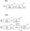
- FIG. 1 shows a filter converter 101 being connected to an embodiment of a filter compressor 102 .
- the filter converter 101 will be described in more detail later on.
- the embodiments of a filter converter 101 is provided with an input signal comprising information concerning a finite impulse response h(n) of a filter or a filter element in the time-domain.
- the index n is in this context an integer indicating different values or samples of the finite impulse response (FIR), wherein h(n) is a real-value number.
- the finite impulse response of a time-domain filter h(n) is a response of a filter or filter element in the time-domain upon an excitation in the form of a single impulse having a defined amplitude.
- the complete behavior of the filter element in the time-domain is comprised in the finite impulse response of the filter.
- the impulse response of the filter can be determined or measured by applying an input signal having at a single instance in time a value which is different from zero. This value can, for instance be equal to 1.
- the filter converter 101 is capable of providing a set of finite impulse responses H(n,k) which can be used in the framework of an adaptable filter, as will be outlined in the context of Fig. 10 .
- Both, l and k are integers.
- the number of subbands L is also a positive integer.
- the number L of the subbands provided by the filter converter 101 and later on used for filtering digital audio input signals is often a power of 2, e.g. 16, 32, 64, 128, 256, 512.
- every positive integer L as a number of subbands in applications components and embodiments of a filter compressor can be employed.
- the time-domain filter h(n) is input into the filter converter 101 that produces a complex QMF or subband representation of the filter H(n,k) .
- the filter H(n,k) is subsequently input to the filter compressor 102 , according to the present invention, that outputs ⁇ (n,k) as a compressed subband filter impulse response.
- the embodiment of the filter compressor 102 outputs a filter ⁇ (n,k) that has a higher number of zero-valued coefficients than the original filter H(n,k) has, and therefore allows for lower computational complexity.
- This option is indicated in Fig. 1 by the slash (/) crossing the connection of the filter converter 101 and the filter compressor 102 .
- the two components may also be coupled to each other by a lesser number of connections or even by only a single connection, over which the corresponding signals or information are transmitted.
- a possible parallel connection of elements comprising an individual connection for each subband is shown where appropriate.
- any connection can be implemented.
- filter compressor 102 also outputs a set of or a plurality of filter impulse responses for a respective number of subband filters comprised, for instance, in a subband filterbank.
- the input subband filter impulse responses H(n,k) and the compressed subband filter impulse responses ⁇ (n,k) are both complex-valued numbers arranged in a two-dimensional matrix being labeled by the time-related n and the subband-related k as explained previously.
- a general use-case scenario for the present invention is outlined.
- the time-domain filter h(n) is again input to the filter converter 101 that produces a complex QMF representation of the filter H(n,k)
- the complex QMF filter H(n,k) is input to an embodiment of a filter compressor 102, that outputs the reduced or compressed complex QMF filter ⁇ (n,k) , as previously explained.
- the use-case scenario shown in Fig. 2 further comprises a QMF analysis filterbank 203 , which is also referred to as a complex analysis filterbank.
- the QMF analysis filterbank 203 is provided with an input signal x(n) , which can for instance be a digital audio signal.
- the QMF analysis filter domain 203 provides at an output a complex QMF representation X(n,k) of the input signal x(n).
- the integers n and k relate to the sample or time index and the subband index, respectively.
- a possible solution for a QMF analysis filterbank 203 will be explained in more detail in the context of Fig. 9 .
- the complex QMF representation X(n,k) of the input signal x(n) is subsequently provided to a filtering stage 201 operating in the subband domain.
- the filtering stage or subband filter 201 is an adjustable subband filterbank, which comprises a plurality of L intermediate filters which are coupled to the output of the embodiment of a filter compressor 102 .
- the intermediate filters of the subband filterbank 201 are provided with the compressed subband filter impulse responses ⁇ (n,k) that is used to filter the (complex-valued) QMF representation X(n,k) .
- the complex QMF representation X(n,k) can be filtered by calculating the convolution of the complex QMF representation X(n,k) and the respective filter impulse response ⁇ (n,k) provided by the embodiment of the filter compressor 102 for each subband identified by the subband index k .
- the filter signal provided by the subband filterbank 201 in the complex QMF domain is then provided to a QMF synthesis filterbank or complex synthesis filterbank, which finally synthesizes the (real-value) output signal y(n).
- a QMF synthesis filterbank 202 or a complex synthesis filterbank will be discussed in the framework of Figs. 11 and 12 .
- the signal x(n) is input to a QMF analysis 203 module that outputs X(n,k) , i.e. a complex QMF representation of the input signal.
- the signal is subsequently filtered 201 in the QMF domain using the complex QMF filter output by the filter compressor 102 , and the filtered signal is finally synthesized to the time-domain by the QMF synthesis filterbank 202 producing the filtered output signal y(n) .
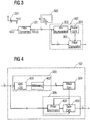
- Fig. 3 a more detailed view of the embodiment of the filter compressor 102 is given.
- the time-domain filter h(n) as the input impulse response in the time-domain is input to the filter converter 101 .
- the time-domain impulse response of the filter is displayed by 301 .
- the time-domain filter is transferred to the subband domain and is represented by H(n,k) .
- An absolute valued time/frequency plot of the filter response is given by 302 .
- the embodiment of the filter compressor 102 shown in Fig. 3 comprises an absolute value representation module 303 , which is connected to the input of the embodiment of the filter compressor 102 .
- the embodiment of the filter compressor 102 furthermore comprises a mask generator 304 , which is coupled to an output of the absolute value representation module 303 .
- a filter calculator 305 is also comprised in the embodiment of the filter compressor 102 , which is connected to both, the input of the embodiment of the filter compressor 102 and an output of the mask generator 304 .
- the filter calculator 305 comprises an output, which also represents an output of the embodiment of the filter compressor 102 .
- the complex QMF filter or subband input filter H(n,k) is input to the embodiment of the filter compressor 102 , that comprises the absolute value representation module 303 , the filter mask generator 304 , and the filter calculator 305 .
- the absolute value representation module 303 creates an absolute valued time/frequency plot of the filters, as exemplified by the partial figure 302 . This can, for instance, be a logarithmic representation of the absolute values of the filter coefficients in the QMF domain, as will be outlined later.
- the filter mask generator 304 selects or determines in one embodiment the coefficients (n,k) that have the largest values in the absolute valued representation of the filter in the QMF domain based on the information provided by the absolute value representation module 302 .
- the filter mask generator 304 determines or selects an adjustable, programmable, fixed or predetermined number of coefficients that depends on the amount of filter compression that is desired. A lower number of selected filter coefficients gives a higher complexity reduction. Examples and more details will be explained in the further course of the application. In many cases in the framework of the present description, the words determining, selecting, deciding on, establishing and finding can hence be used synonymously. In many cases filter impulse response values being determined or selected are such filter impulse response values, which have (or comprise) higher values as compared to filter impulse response values having lower values than the higher values. These lower valued filter impulse response values are also referred to as being not selected or not determined.
- the complexity reduction may also be achieved based on examining the filter taps or filter impulse response values compared to the so-called aliasing level of the filterbank corresponding to the filter impulse response as provided to an embodiment of a filter compressor. If certain taps of the filter impulse response values in the QMF domain are close to the aliasing level of the filterbank, these filter taps may safely be set to zero or treated otherwise to reduce the computational complexity. These filter taps may then safely be disregarded in the case of an implementation of a filter as zero-valued coefficients are not required to be included in the framework of a multiply-add in an implementation of such a filter.
- some of the time-frequency tiles in the complex QMF representation can have low absolute values at the aliasing level of the corresponding MPEG surround filterbank.
- These entries in the complex QMF representation of the HRTF filters may then be set to zero, which enables a complexity reduction for implementing long HRTF filters with room-response included.
- the filter mask generator creates, based on the information provided by the absolute value representation module 302 a filter mask M(n,k) and outputs the selected filter mask M(n,k) , indicating the selected filter coefficients of H(n,k) to the filter calculator 305 .
- the filter calculator 305 produces a new, compressed filter ⁇ (n,k) from the original filter H(n,k) in the QMF domain comprising the selected filter coefficients. Further details on different possibilities concerning implementations will be given below.
- Fig. 4 shows a further embodiment of a filter compressor 102 , which has the same basic structure as the embodiment of the filter compressor 102 shown in Fig. 3 .
- the embodiment of the filter compressor 102 shown in Fig. 4 also comprises an absolute value representation module 303 which is on the one hand, connected to an input of the embodiment of the filter compressor 102 and on the other hand, via an output of the absolute value representation module 303 to a mask generator 304 .
- the embodiment of the filter compressor 102 in Fig. 4 also comprises a filter calculator 305 , which is also connected to the input of the filter compressor and to an output of the mask generator 304 .
- An output of the filter calculator 305 once again represents an output of the embodiment of the filter compressor 102 shown in Fig. 4 .
- the absolute value representation module 303 as well as the filter calculator 305 are shown in more detail in the case of the embodiment shown in Fig. 4 and will be explained in more detail along with alternative or further implementations in the following sections of the present patent application.
- the absolute value representation module 303 comprises an absolute value algorithmic function module 401 , which is connected in series with a whitening module 402 in between the input and the output of the absolute value representation module 303 .
- the filter calculator module 305 comprises a filter decimator module 403 , which is connected in series with a gain calculator 404 . Both, the filter decimator module 403 and the gain calculator 404 are connected in series between the input and the output of the filter calculator module 305 .
- the information concerning the mask as provided by the mask generator 304 will be provided to the filter decimator module 403 and optionally also to the gain calculator module 404 , as indicated in Fig. 4 .
- the gain calculator module 404 may be optionally provided with the input subband filter impulse responses H(n,k) , as provided to the embodiment of the filter compressor 102 via the optional connection between the gain calculator module 404 and the input of the filter calculator module 305 , as indicated by the dashed line in Fig. 4
- the different embodiment of the filter compressor 102 according to the present invention is outlined.
- the absolute value representation module 303 comprises the absolute values and logarithmic function 401 , and a whitening module 402 that performs a spectral whitening of the absolute valued representation supplied by the absolute values and logarithmic function module 401 .
- the filter mask generator 304 is the same as before, and outputs the filter mask M(n,k) to the filter calculator module 305 .
- This comprises the filter decimator module 403 that keeps the selected coefficients of the filter H(n,k) and sets the other coefficients to zero in this embodiment, and the gain calculator module 404 , that adjusts the gain of the filter so that the gain of the compressed filter ⁇ (n,k) is the same as that of the original filter H(n,k) .
- the evaluation representation A(n,k) as indicated by equation (1) reflects a volume distribution with respect to the human ear without taking into account the specific acoustic characteristics of the human ear.
- evaluation representations A(n,k) can be implemented in the framework of the absolute value representation module 303 .
- the evaluation representation A(n,k) according to equation (1) is based on a decibel scale based on the energy
- further ways of calculating the evaluation representation can be employed by, for instance, implementing psycho-acoustic models. It is important to note that in the embodiment shown in Fig. 4 as well as in the embodiment shown in Fig.
- the filter converter 101 creates, based on the real-valued time-domain impulse response h (n) a complex-valued input subband filter impulse response H(n,k) so that for mathematical reasons, to be able to compare different impulse response values of the corresponding input subband filter impulse response H(n,k), a mathematical measure is advisable to be applied to the input subband filter responses.
- this mathematical measure is the absolute value as indicated by
- other mathematical measures can also be applied, such as taking the real part, taking the imaginary part, taking the angle of the corresponding complex number with respect to the positive direction of the real-valued numbers in the plane of the complex numbers.
- the partial figure 302 in Fig. 3 schematically representing the evaluation representation A(n,k) can be understood as a three-dimensional plot of the evaluation representation A(n,k) as a function of the two indices k, n in the plane shown in Fig. 3 , while the evaluation representation values A(n,k) are plotted perpendicular to the n-k-plane of the partial figure 302 .
- the partial figure 302 shows a schematic representation of the evaluation representation of the absolute valued time/frequency representation of the filter A(n,k) as a function of the sample index or time index n and the subband index k.
- the time index or sample index n may differ from the index n of the time-domain impulse response h(n) , for instance, by a factor of L (number of subbands).
- the filter converter 101 may comprise a complex-modulated analysis filterbank, which in turn may comprise one or more downsamplers, which reduce the number of samples by a factor, which can for instance be the number of subbands L .
- the index n may either refer to a time index or sample index comparable to the index n of the time-domain impulse response H(n), or may correspond to a downsampled time index or sample index differing from the time or sample index n of the time-domain impulse response H(n) , for instance, by a factor of L.
- the purpose of the whitening module taught by the present invention is to enable a perceptual weighing of filters prior to the mask generation in order to avoid the situation where perceptually important filter taps are discarded, because they have a small absolute value, in favor of other perceptually less important filter taps.
- whitening and weighing can be used synonymously in the framework of the present application.
- the (spectral) whitening is based on the finding that it may be advisable to transfer energy from spectral parts to different spectral parts to prevent or to minimize distortion created in the course of the filter compression.
- Real-life filters and audio systems very often have an unevenly distributed time/frequency distribution, which may result in the filter impulse responses in the subband domain having significantly larger lengths comparing subbands located at lower frequencies than subbands being located at higher frequencies. Furthermore, the unevenly distributed amplitude/frequency distributions of real-life filters and audio systems may also lead to different relevancies of the individual subband filters with respect to each other. In other words, for instance, due to a higher dampening of real-life filters and audio systems at higher frequencies subband filters corresponding to higher frequencies may be less important as compared to subband filters corresponding to lower frequencies.
- the (spectral) whitening can be favorably implemented to prevent in the scenario outlined above, subband filters at higher frequencies from being completely suppressed in the course of the compression, leading to severe distortions of the listening experience.
- (spectral) whitening also referred to as weighing, may be a crucial point for real-life filters and audio systems.
- the whitening module 402 as comprised in the absolute value representation module 303 in the embodiment shown in Fig. 4 , therefore applies a spectral whitening in which a normalization effect is employed by dividing the overall frequency range in frequency bands.
- each subband corresponds to a specific frequency range with a specific center frequency.
- the subbands can be arranged according to the center frequencies.
- the subband index k corresponds in increasing order to the center frequencies in increasing order.
- perceptually relevant intervals of subbands or subgroups of subbands are formed, which comprise at least one subband each.
- an individual subband belongs to exactly one subgroup as a whole.
- each subgroup of subbands may comprise more than one subband.
- a subgroup typically only comprises subbands with neighboring center frequencies.
- each frequency band can be represented by a subgroup or an interval of subbands, which is a superset of the subbands.
- a subgroup of subbands may also comprise exactly one subband.
- the whitening therefore leads in many real-life filters and audio systems to a transfer of the energy from lower spectral parts to higher spectral parts, optionally based on the perception characteristics of the human ear with respect to psycho-acoustic models.
- whitening module 402 can easily be implemented in the framework of the absolute value representation 303.
- alternative implementations comprise the possibilities of individually whitening the evaluation representations A(n,k) for each subband with index k instead of the performing the whitening based on all subbands comprised in the respective subgroup of subbands according to equation (4).
- a whitening may be performed by dividing all values of the evaluation representation A(n,k) and thereby normalizing all values of the evaluation representation with respect to the maximum of each subband or with respect to the maximum value of each subgroup of subbands.
- the described normalization by dividing the valuation representation can also be carried out such that the sum of all values of the respective evaluation representation A(n,k) (either with respect to each individual subband or with respect to each subgroup of subbands) can be carried out.
- the sum of all values of the evaluation representation with respect to the respective subband or the respective subgroup of subbands will be determined, which is then followed by the subtracting according to equation (4) or by dividing the values of the evaluation representation with the respective sum value.
- the examination as well as the selecting is based on the absolute value of the filter impulse response values at the filter taps.
- the filter impulse response values are selected or not selected based on a comparison concerning the absolute values of the filter taps when selecting at least one comprising a higher value.
- the comparison or examination of the filter taps may be based on applying other mathematical measures, if necessary. If the filter taps are real-valued, in principle an application of a mathematical measure is not required, however, calculating or determining the absolute value may be implemented.
- the whitened evaluation representation A W (n,k) as output by the whitening module 402 is provided to the mask generator 304 , which creates a filter mask or mask M(k) based on the whitened evaluation representation. Due to the fact of the whitening module 402 on the evaluation representation, the mask generator 304 is now capable of selecting the most (perceptually) relevant filter coefficients.
- the concrete implementation of a mask generator 304 can substantially differ from one embodiment to the next embodiment of a filter compressor 102 .
- a specific absolute number of impulse response values also a relative number with respect to the overall number of impulse response values given by the set of subband filter responses H(n,k) is possible.
- the overall matrix of the input subband filter responses is given by a 64 • 16 matrix containing 1024 impulse response values.
- the mask generator 304 may be adapted to receiving a signal indicative of the absolute number of impulse response values to be selected or indicative of the ratio of impulse response values with respect to the overall number of impulse response values.
- the compression ratio can be adjusted by adjusting the previously mentioned figures.
- the mask generator 304 may alternatively or additionally, be adapted to selecting the respective filter impulse response values based on different criteria.
- the mask generator 304 may be adapted to selecting a predetermined, fixed, programmable, or adaptable number of impulse response values per subband (e.g. the 3 impulse response values having the maximum values with respect to the evaluation representation for each subband).
- the mask generator 304 may be adapted such that a threshold criteria holds, so that for instance, all impulse response values are selected, the corresponding evaluation representation values of which are larger than a predetermined, fixed, adjustable or programmable threshold value.
- mask generator 304 it may be advisable to adapt the mask generator 304 such that it is capable of selecting the impulse response values, based on a comparison of the respective value, with its neighboring impulse response values.
- mask generator 304 may be adapted such that a filter impulse response value is not selected if the respective value is in view of the (optionally whitened) evaluation representation smaller than a fixed, predetermined, programmable or adjustable ratio compared to the neighboring values (e.g. smaller than 25%).
- a fixed, predetermined, programmable or adjustable ratio compared to the neighboring values
- At least one impulse response value is selected in each subgroup of subbands or in each subband, depending on the concrete implementation, although the number of selected impulse response values may substantially differ from one subband to the next subband, or from one subgroup to the next subgroup.
- the whitening carried out by dividing the evaluation representation A(n,k) by, for instance, the maximum value of the corresponding subset of evaluation representation values, in the above described implementation of the mask generator 304 , at least one filter impulse response value is selected in each subband or in each subgroup of subbands, as will be explained in the context of Fig. 14 .
- the interplay of the absolute value representation module 303 and the mask generator 304 will lead to a concentration to the important areas of the filter impulse response values in the n-k-plane (cf. partial figure 302 in fig 3 ), and to a "compression” of "vacuum” or "air” in between the perceptually relevant areas of the n-k-plane.
- the relevant impulse response values will be disregarded by setting the mask M(n,k) accordingly.
- the filter calculator module or filter impulse response constructor also referred to as the filter calculator module 305 , comprises in the embodiment shown in Fig. 4 as one element, a filter decimator 403 , which sets all the non-selected filter taps or filter impulse response values to zero, as indicated by the filter mask M(n,k) .
- the decimator 403 outputs in this case a masked matrix of a subband filter impulse responses H M (n,k) , which is equal to the corresponding matrix element of the subband filter impulse responses H(n,k), if the corresponding filter mask value M(n,k) is equal to 1.
- the filter mask of a corresponding filter impulse response value M (n , k) is set to 0
- the masked matrix of subband filter impulse responses H M (n,k) is set to 0.
- the mask consists of entries that are either zero or one.
- the entries with zeros describe which filter coefficients are to be discarded and the entries with ones describe which filter coefficients are to be kept (selected).
- the gain calculator module 404 comprised in the filter calculator module or rather filter impulse response constructor 305 is outlined.
- the purpose of the gain calculator module 404 taught by the present invention is to readjust the power gain of the decimated filters such that the final gain adjusted compressed filter has the same main spectral characteristic as the original filter. As the power gain of the decimated filter is lower than the original filter a compensation gain is computed in the gain calculator module 304 for each subband.
- G max is an upper bound on the gain compensation and ⁇ is a small positive number included for avoiding division with zero.
- G max and ⁇ are therefore numbers, which are useful in a numerical implementation of the gain calculator 404 to prevent a division by a zero (i.e. ⁇ > 0), and to limit the gain applied by the gain calculator module 404 to a subband to the value as defined by the maximum gain G max , as due to the minimum of the two terms in the braced brackets in the equations (6), (8), the respective gains G(k) and G(p) are limited to the value of G max .
- adjusting the gain in each of the P frequency bands or rather subgroups of subbands keeps the energy of the signal filtered by the respective subband filter in a very good approximation constant, when comparing the masked and non-masked subband filter impulse responses H M (n,k) and H(n,k) .
- the energies of the signals filtered with the respective filters based on the filter impulse responses are in both cases proportional to the sum of the squares of the absolute values of the respective subband filter impulse response values, as indicated by the expressions E ⁇ ⁇ H n k 2 and E ⁇ ⁇ H M n k 2 for the masked and the original input subband filter impulse response values.
- the gain G(k) and G(p) in the equations (6), (8) are based on a comparison of the two energies as outlined in equations (10a) and (10b), wherein the additional addend ⁇ has only been introduced to the equations (6), (8), to avoid in a concrete implementation a division by zero.
- a gain calculator module 404 normalizes the masked filter taps H M (n,k) with respect to the energy to compensate the energy lost in the course of the masking of at least some of the input subband input responses.
- a signal filtered with a subband filter input response corresponding to the masked subband filter impulse responses H M (n,k) will have a lesser energy compared to a subband filter employing the subband filter impulse responses H(n,k) .
- the gain calculator module 404 can also be adapted to applying a different gain scheme. As an example, not so much the energy but a direct comparison of the absolute values of the subband filter impulse responses can be employed to determine a gain factor. Additionally, or alternatively, the gain factor G can also be determined, based on the overall number of subband filter impulse response values, rather than the impulse response values of an individual subband or an individual subgroup of subbands, as explained in the context of equations (6) and (8). Moreover, it should be noted that a gain calculation module 404 is not a required component, but rather an optional component.
- the filter impulse response constructor or filter calculator module 305 can in further embodiments of the present invention, be capable of constructing the compressed subband filter impulse responses, not only by setting the non-selected subband filter impulse response values to zero as explained above. Depending on the concrete implementation, the filter impulse response constructor 305 can achieve this, for instance, by weighing, copying or taking the appropriate selected or determined subband filter impulse response values to construct the compressed subband filter impulse responses.
- the compressed subband filter impulse responses may comprise zero-valued values corresponding to the filtered taps of not-selected filter impulse response values or the compressed subband filter impulse responses may not include the respective not-selected filter impulse response values at all.
- the filter impulse response constructor 305 can, for instance be capable of constructing a compressed subband filter impulse response having in principle the same number of subband filter impulse response values as the input subband filter impulse responses, but with an increased number of zero-valued values or the compressed subband filter impulse responses may have a shorter overall length, as the filter impulse response constructor 305 only copies the selected values and disregards the not-selected values.
- the filter impulse response constructor 305 can also advantageously output the absolute values of some of the selected filter impulse response values. This mode of operation is particularly attractive in subbands corresponding to higher frequencies where the human hearing is less sensitive to phase relations.
- subband impulse response values of subbands corresponding to center frequencies above a border frequency can optionally be replaced by an absolute value, an imaginary part, a real part, a phase, a linear combination, a polynomial combination or a real-value expression of at least one of the aforementioned elements.
- the imaginary part of a complex value is also considered to be a real-valued number in the framework of the present description.
- the border frequency can be in the range of 1 kHz to 10 kHz, whereas in many applications an implementation of a border frequency in the range between 1 kHz to 5 kHz or 1 to 3 kHz may be utilized considering a typical hearing characteristic of a human being.
- the described replacement of a complex-valued filter impulse response value by a real-valued value based on the complex-valued filter impulse response value may be implemented depending on the filter impulse response value being selected or determined or not being selected or not being determined.
- filter impulse response values belonging to subbands corresponding to center frequencies above the border frequency may generally be replaced by corresponding real-valued values based on the complex-valued filter impulse response values.
- using determined or selected filter impulse response values also comprises using (e.g. real-valued) values based on such filter impulse response values to replace the corresponding filter impulse response values.
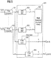
- Fig. 5 shows further embodiments of a filter compressor 501 , according to the present invention operating on multiple filters simultaneously.
- a different embodiment is outlined.
- N 10 time-domain filters.
- the filter compressor 501 shown in Fig. 5 is provided with a plurality of sets of impulse responses, wherein each set of filter impulse responses of the plurality of sets is provided by a different filter converter 101 in the case illustrated in Fig. 5 .
- the set of filter impulse responses comprises L individual filter impulse responses, each having a specific number of filter taps or filter impulse response values.
- each filter impulse response corresponding to an individual subband is associated to a center frequency thereby the center frequencies form a plurality of center frequencies.
- Filter impulse responses corresponding to the same subband index k but belonging to different sets of filter impulse responses as indicated by the index v , also correspond to the same center frequency.
- each center frequency of the plurality of center frequencies corresponds (exactly) one filter impulse response in each of the sets of filter impulse responses, at least before the compression.
- Each of the filter converters 101 provides for each of the time-domain filters, a set of complex valued subband filter impulse responses H v (n,k), which are provided to the embodiment of the filter compressor 501 shown in Fig. 5 .
- Each of the subband filter impulse responses for the N different time-domain filters is provided to an individual absolute value representation module 303 , which provides an absolute value representation or an evaluation representation for each of the N time-domain filters to the filter mask generator 502 .
- the absolute value representation modules 303 can be taken from one of the other embodiments of an inventive filter compressor outlined in the present application as indicated by the same reference sign.
- This (joint) absolute value representation forms the basis for a single mask generation M(n,k) exactly as in the single filter mask generator 304 in the previous embodiments. In case a whitening step is performed, this can either be done for each individual absolute value representation modules 303 or performed only once for the joint absolute value representation.
- the filter mask generator 502 in this embodiment creates a single filter mask M(n,k) for all filters based on the N absolute value representation of all filters. This is a great advantage of the embodiment of the present invention, since the filter mask generator 502 can take into account how the compressed filters will be combined in a later state.
- Each of the original filters is input to a filter calculator 305 as outlined before, and the filter compressor produces N new filters A W v (n,k), as each of the filter calculators is provided with the same mask M(n,k).
- the calculation of the absolute value representation according to equation (11) represents a specialized form of the absolute value representation according to equation (11') which offers a greater flexibility as it allows for weighing of the perceptual importance of the respective filters indicated by the index v .
- the embodiment of the filter compressor 501 is capable of creating a set of compressed subband filter impulse responses for each of the N filters such that even a post-processing of the N individual subband filters after the filter compressor 501 will not lead to a resulting compressed subband filter impulse response having an entry with a relevant impulse response value that does not have corresponding selected impulse response value in one of the other filters.
- the mask generator 502 although provided with N input subband filter impulse responses for N individual filters in the time-domain only, produces a single mask M(n,k) indicative of all the N subband filter impulse responses.
- different mask generators 502 may be employed, which can in principle use different schemes to provide a common evaluation representation for all the N filters in the time-domain.
- the individual evaluation representations as provided by the absolute value representation modules 303 may be combined to a single evaluation representation by summing the respective values, by linear combining the respective values, wherein, for instance, a weighing with respect to the subbands involved can be implemented, or by employing a more complex combination (e.g. a quadratic or higher order combination) of the respective values of the evaluation representations.
- the filter converter 601 receives a total of N ⁇ L filter impulse responses, wherein L is again the number of subbands.
- the ten HRTF filters in the QMF domain representation are input to an embodiment of a filter compressor 501 , as outlined above, and provide ten compressed and optionally gain adjusted filters H ⁇ (n,k) .
- the binaural decoder 602 accomplishes this by linearly combining the ten HRTF filters into four HRTF filters that are applied to the stereo input signal.
- the embodiment of the filter compressor 501 is designed to create the same filter mask for all filters, so that when they are linearly combined, an entry in one filter that has been set to zero does not have a corresponding non-zero entry in any other filter.
- each connection coupling the filter converter 601 , the filter converter 501 and the binaural decoder 604 transfers information concerning L subbands as indicated by the slash in Fig. 6 .
- the binaural decoder 602 combines the 10 (five audio input channels for two audio output channels (stereo)) into four HRTF filters, which can immediately be applied to the stereo input signal 603 .
- the HRTF filters do depend on the spatial parameters 604 provided to the binaural decoder 602 to render the binaural stereo signal 605 .
- especially HRTF filters can comprise a substantial number of non-trivial, non-zero or non-vanishing subband filter impulse response values as filter taps, as often very complex interactions between the binaural stereo output signals for the human ear and the sound sources have to be modeled.
- the respective HRTF filters can for instance become substantially long in order to effectively model the room characteristics of the environment and other influences to be modeled.
- a filter compressor 501 can efficiently be applied to reduce the computational complexity in terms of the binaural decoder 602 significantly.
- the binaural decoder 602 can be implemented with lesser computational power, which ultimately leads to a lower energy consumption, as for instance the clock rate of the corresponding binaural decoder can be reduced due to a lower number of calculations in a given period of time.
- the binaural decoder 602 can be built smaller for the same reasons so that in principle a second processing core may be avoidable.
- Fig. 7 shows a possible solution for a filter or filtering element 700 , to which a digital audio input is provided.
- the digital audio input could in principle be both, a time-domain signal and a signal in the (complex) subband domain.
- the filter element provides at an output, a digital audio output, which represents the filtered digital audio input, depending on a filter definition signal or a respective filter impulse response signal.
- a digital audio input x(n) being either a real-valued or a complex-valued input signal, depending on the domain involved
- the digital audio output signal y(n) as well as the impulse response signal f(n) of the filter 700
- l is a summing index used to calculate the resulting digital audio output signal, based on the convolution as given by equation (12).
- a filter converter 101 comprises, as shown in Fig. 8 a complex analysis filterbank 710 as a central component to which the corresponding filter impulse response signal is provided.
- the complex analysis filterbank 710 analyzes impulse response signals of the filter in the time-domain, which is to be transferred into the QMF domain, by means of filtering with a set of L analysis filters, followed by an optional downsampling of a factor L, wherein L is once again the positive integer, preferably larger than 1 and indicating the number of subbands of the complex analysis filterbank 710 .
- the analysis filters are usually obtained by a complex modulation of a prototype filter q(n), wherein n is once again a positive integer indicating the index in an array of data or an index of a value in a signal.
- the output of a filterbank 710 consists of L subband signals, which as a whole, represents the filter characterized by its filter impulse response in the time-domain in the complex QMF domain.
- the output of a complex analysis filterbank 710 is a set of subband filter impulse responses, which can be provided to a filter element 700 to perform a filtering of an audio input signal in the complex QMF domain, which leads to a perceptually indistinguishable difference of the audio output signal, compared to a direct filtering in the time-domain.
- Fig. 9 shows a possible solution of a complex analysis bank 710 in more detail.
- the complex analysis bank 710 comprises a plurality of L intermediate analysis filters 720 for each subband to be output by the complex analysis bank 710 .
- each of the L intermediate analysis filters 720 is connected in parallel to a node 730 to which the time-domain impulse response signal as an input signal to be processed is provided.
- Each of the intermediate analysis filters 720 is adapted for filtering the input signal of the complex analysis bank 710 with respect to a center frequency of each subband. According to the center frequencies of the different subbands, each subband is labeled by a subband index or index k, wherein k is again a non-negative integer, typically in the range from 0 to ( L- 1).
- the intermediate analysis filters 720 of the complex analysis bank 710 can be derived from a prototype filter p(n) by a complex modulation according to the subband index k of the subband to which the intermediate analysis filter 720 is applied. More details concerning the complex modulation of a prototype filter are explained below.
- the intermediate analysis filters 720 Either directly by the intermediate analysis filters 720 or by an optional downsampler 740 (denoted by dotted lines in Fig. 8 the sampling frequency of the signal output by the intermediate analysis filters 720 is reduced by a factor L .
- the downsamplers 740 supplied to each subband signal output by the corresponding intermediate analysis filters 720 are optional as, depending on the concrete implementation, the downsampling can also be carried out in the frame work of the intermediate analysis filters 720 . In principle, downsampling the signal output by the intermediate analysis filters 720 is not required. Nevertheless, the presence of the explicit or implicit downsamplers 740 my be a favorable option in some applications as the amount of data provided by the complex analysis bank 710 would alternatively be raised by a factor of L , leading to a significant redundancy of data.
- Fig. 10 shows a possible solution a subband filtering 750 and its interplay with the filter converter 101 in more detail.
- the subband filtering 750 comprises a plurality of intermediate filters 760 , wherein one intermediate filter 760 is provided for each complex valued subband signal provided to the subband filtering 750 .
- the subband filtering 750 comprises L intermediate filters 760 .
- the filter converter 101 is connected to each of the intermediate filters 760 .
- the filter converter 101 is capable of providing the filter taps for each of the intermediate filters 760 of the subband filtering 720 . More details concerning the filtering done by the intermediate filters 760 will be explained in the further course of the application.
- the filter taps provided to the different intermediate filters 760 and output by the filter converter 101 form the intermediate filter definition signal.
- delays or delayers can be comprised in elements shown (e.g. filters) or added as optional elements in all embodiments, solutions and implementations, depending on their concrete implementation.
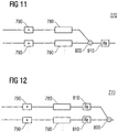
- Fig. 11 illustrates a possible solution for a complex synthesis bank 770 .
- the complex synthesis bank 770 comprises L intermediate synthesis filters 780 to which L subband signals are provided to.
- the subband signals are upsampled by L upsamplers 790 , which reconstruct the sampled frequency of the subband signals by increasing the sampling frequency by a factor of L .
- the optional upsampler 790 reconstruct or reform the subband signals provided to the upsampler 790 in such a way that the information contained in each of the subband signals is retained while the sampling frequency is increased by a factor of L .
- the upsamplers 790 are optional components, as the upsampling can also be carried out in the frame work of the intermediate synthesis filters 780 . Hence, the step of upsampling the subband signals carried out by the upsampler 790 can be simultaneously processed in the framework of the intermediate synthesis filers 780 . If, however, the downsamplers 740 are neither explicitly nor implicitly implemented, the upsamplers 790 do not have to be either implemented explicitly or implicitly.
- the intermediate synthesis filters 780 are connected via an output to an adder 800 which sums up the filtered subband signals output by the L intermediate synthesis filters 780 .
- the adder 800 is further connected to a real part extractor 810 , which extracts or forms a real-valued signal or rather a (real-valued) time-domain output signal based on the complex-valued signal provided by the adder 800 .
- the real part extractor 810 can perform this task for instance by extracting the real part of a complex-valued signal provided by the adder 810 , by calculating the absolute value of the complex-valued signal provided by the adder 810 or by another method that forms a real-valued output signal based on a complex-valued input signal.
- the second possible solution for a complex synthesis bank 770 shown in Fig. 12 differs from the first possible solution shown in Fig. 11 only concerning the real part extractors 810 and the adder 800 .
- the outputs of the intermediate synthesis filters 780 are connected separately from each subband to a real part extractor 810 extracting or forming a real-valued signal based on the complex-valued signal output by the intermediate synthesis filters 780 .
- the real part extractors 810 are then connected to the adder 800 , which sums up the L real-valued signals derived from the L filtered subband signals to form the real-valued output signal provided by the adder 800 .
- Fig. 3 illustrates a possible selection of a filter converter 101 .
- the filter is assumed to be given by its impulse response. Viewing this impulse response as a discrete time signal, it is analyzed by the L -band complex analysis (filter) bank 710 .
- the resulting subband signal outputs are then exactly the impulse responses of filters to be applied separately in each subband in the subband filtering 705 shown in Fig. 10 .
- the filter definition signal provided to the filter converter 101 and its complex analysis bank or complex analysis filter bank 710 is the impulse response signal indicative of the amplitude/frequency characteristic of a filter, which is to be transferred into the subband domain.
- the output of the complex analysis (filter) bank 710 of each of the L subbands represents the impulse response of the intermediate filters comprised in the subband filtering 750 .
- the complex analysis bank 710 is in principle derived from an analysis bank for an audio output signal, but has a different prototype filter and a slightly different modulation structure, the details of which will be outlined in the following description.
- the length of the prototype filter q(v) can be designed to be comparably small. Due to the downsampling by a factor L , the length of subband filters are also a factor of L smaller than the sum of the lengths of the given time-domain filter and the prototype filter q(v) .
- a non-vanishing tap or value is a tap or a value, which is ideally not equal to zero.
- a non-vanishing value or tap is a real-valued or complex-valued tap or value with an absolute value which is larger than a predetermined threshold, e.g. 10 - b or 2 - b , wherein b is a positive integer depending on the requirements of a concrete implementation.
- this threshold is preferably defined in the binary system (basis 2), wherein the integer b has a predetermined value depending on the specifics of the implementation.
- the value b is 4, 5, 6, 7, 8, 10, 12, 14, 16 or 32.
- n is an integer indicating an index or a time index of a time signal
- the complex exponential modulated L- band filterbank is defined from a real valued prototype filter p(v) of finite length. For the computations below it will be assumed by extension with zeros that the prototype filter is defined for all integers n .
- the time index m differs from the time index n with respect to the fact that m refers to the downsampled signals, whereas the integer n refers to signals with the full sample frequency.
- the perfect reconstruction property will hold true up to a delay (and/or a sign change), but in the computations that follow, this detail will be ignored by allowing the use of an acausal prototype filter, as also explained in the case of the pseudo QMF type of design as in PCT/SE02/00626 "Aliasing reduction using complex exponential modulated filter banks".
- the perfect reconstruction is also replaced by a near-perfect reconstruction property.
- H ( ⁇ ) be a given filter (e.g. transfer function) with real-valued impulse response h(n). This data is considered as input to the filter converter 101 .
- the drawback of this formula is that although H( ⁇ ) is a smooth function of ⁇ , the periodized segment of it defined by (20) will exhibit jumps and the impulse response of the subband filters will be unnecessarily long.
- any given filter h(n) can be efficiently transformed into intermediate subband filter responses.
- q(n) has K Q ⁇ L taps
- a time-domain filter h ( n ) of K H ⁇ L taps is converted into subband domain filters (24) with ( K H + K Q - 1 ) taps, wherein K H and K Q are positive integers.
- This prototype filter corresponds to the choice (20) and has the disadvantage of having an infinite and slowly decaying impulse response q(n). Instead, equation (17) is solved approximately (e.g. in the least-square sense) with a finite impulse response filter q(n).
- the system of linear equations (28) can be solved in the least squares sense for a prototype filter q(n). It is desirable to use a support significantly shorter than that of the original filter bank prototype filter p(n), and in that case the linear system (28) is over-determined. A given quality of approximation can also be traded for other desirable properties via joint optimization.
- One example of such a property is a low pass type of frequency response Q( ⁇ ).
- the subband filtering itself is carried out by the intermediate filters 760 inside the subband filtering 750.
- L 64 different subband signals. Nevertheless, this specific number of subband signals is not essential and the appropriate equations will also be given in a more general form.
- the filter converter 101 which converts the given time-domain FIR filter h(n) into the complex subband domain filters g k (l) comprises the complex analysis bank 710.
- l 0 and n 0 are delays
- l is an integer indicating an index of the filter taps
- equation (24) was developed without any regard to casualty of filters. Real implementations will cause always introduce delays. Hence, depending on the concrete implementation, additional delayers or delays can be implemented, which have been omitted for the sake of simplicity in the Figures.
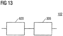
- Fig. 13 shows a simplified block diagram of an embodiment of a filter compressor 102 comprising a processor 820 and a filter impulse response constructor 305 which are connected in series between an input and an output of the embodiment of the filter compressor 102.
- the embodiment of a filter compressor 102 receives at the input, a set of input subband filter impulse responses, having filter impulse response values at filter taps, which are provided to the processor 820.
- the processor 820 examines the filter impulse response values from at least two of the input subband filter impulse responses and is capable of selecting filter impulse response values having a higher absolute value, as explained in the context of Fig. 4 and especially in the context of the absolute value representation module 303 and the whitening module 402, in particular, along with a mask generator 304.
- the processor 820 is capable of not selecting at least one filter impulse response value, having a lower absolute value compared to at least one selected filter impulse response.
- the processor 820 of the embodiment shown in Fig. 13 comprises the functionality of the absolute value representation module 303 and the mask generator 304.
- the filter impulse response constructor, or rather the filter calculator module 305 is capable of constructing compressed subband filter impulse responses using the selected filter impulse response values, wherein the compressed subband filter impulse responses do not include filter impulse response values or zero-valued values corresponding to filter taps of not selected filter impulse response values.
- the filter impulse response filter 305 can be adapted to setting not selected impulse response values to zero or constructing the compressed subband filter impulse responses by copying only the selected impulse response values or by some other means of disregarding the not selected filter impulse response values.
- the embodiment of the filter compressor 102 is capable of carrying out an embodiment of an inventive method of manufacturing compressed subband filter impulse responses from inputs in subband filter impulse responses having filter impulse response values at filter taps.
- manufacturing same can equally be understood as generating or providing the compressed subband filter impulse responses to as system or a computer-readable storage medium.
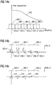
- Fig. 14a shows a schematic representation of an exemplary filter characteristic 850, as a function of the frequency of the filter in the time-domain.
- Each of these frequency bands 860 (using summarizing reference signs as indicated earlier) corresponding to one of the subbands with the respective subband index k can furthermore be characterized in terms of a center frequency, which is indicated in Fig. 14a as a dashed line 870-0, ..., 870-4.
- the center frequency, as well as the frequency bands of the respective subbands are determined by the inner structure of the complex modulated filterbanks employed in the filter converter 101.
- the prototype filter q(n) along with the center frequency depending on the subband index k , as can for instance be seen in the case of equation (14), determines the corresponding frequency bands of the respect subband.
- Fig. 14b shows a schematic representation of the input subband filter impulse responses as provided, for instance by the filter converter 101.
- Fig. 14b shows schematically which indicates the evaluation representation A(k,n) for the different subbands, indicated as a set of arrows 880.
- A(k,n) for the different subbands, indicated as a set of arrows 880.
- a set of three arrows 880 is shown in Fig. 14b for each of the subbands 890-0, ..., 890-4.
- the maximum value of the evaluation representation is determined, and will be subtracted afterwards from each of the evaluation representation values to obtain the whitened evaluation representation A w (k,n), as shown in Fig. 14c .
- the maximum contribution of the evaluation representation will be set to zero, as indicated in Fig. 14c by the dots 910.
- each of the subgroups of subbands 900 comprises at least one whitened evaluation representation value having the value of zero, wherein the rest of the whitened evaluation representation values A w ( k , n ) is smaller than or equal to zero.
- at least one value is set to zero and thereby represents a maximum value so that each of the subgroups of subbands, which were determined according to a psycho-acoustic model in some of the embodiments, in the course of the compression at least one filter impulse response value of each of the subgroups 900 is retained.
- spectral weight or spectral energy is transferred from the subbands having a lower central frequency to subbands having higher frequencies by applying the whitening scheme.
- a direct comparison of Figs. 14b and 14c also underlines this. While in Fig. 14b the evaluation representation values in the subgroup 900-2 are significantly smaller than those of the subgroup 900-1, after applying the whitening procedure, the resulting whitened evaluation representation values in the subgroups 900-2 are significantly larger as compared to at least some of the values of the evaluation representation of the subgroup 900-1.
- the subgroup 900-1 comprises two zero-valued evaluation representation values as indicated by the dots 910, which is caused by the fact that evaluation representations A(k,n) as shown in Fig. 14b of the subgroup comprises two identical maximum values.
- Equation (4) only ensures that at least one value of the evaluation representation of each subgroup is set to zero and thereby represents the maximum value in the context of the whitened evaluation representation A w (k.n).
- Fig. 15 shows a further embodiment of a filter compressor 501 , which is capable of processing more than one input subband filter impulse response H v (n,k) .
- the structure of the filter compressor shown in Fig. 15 is very similar to the one shown in Fig. 5 and differs from that embodiment only with respect to the fact that the absolute value representation modules 303 each comprise an absolute value and logarithmic function module 401 and a whitening module 402, which is also shown and explained in the context of Fig. 4 .
- the filter calculation module or filter impulse response constructor 305 comprises, each a filter decimator module 403, as well as a gain calculator 404 which can be implemented as an optional component in the context of Fig. 4 .
- the embodiment shown in Fig. 15 differs from the embodiment shown in Fig. 5 furthermore with respect the mask generator 502 for multiple filters.
- the mask generator 502 of Fig. 15 comprises an average calculating module 920, which can for instance, implement calculating the joint absolute value representation A(n,k) on the basis of the individual (optionally whitened) absolute value representation A v (n,k) according to equation (9).
- the embodiment 501 shown in Fig. 15 can be regarded as the embodiment in which the processor 820 and the filter impulse response constructor 305' are connected in the series between an input and an output of the respective filter compressor 501 .
- the Figs. 1 to 6 , 13 and 15 can also be considered as flow charts of the respective methods, wherein the "direction of the flow" is comprised in the direction of the signals.
- the figures mentioned above do not only reflect different embodiments of filter compressors 102 , 501 , but do also illustrate both, the methods carried out by these embodiments as well as embodiments of the methods for generating compressed subband filter impulse responses themselves.
- QMF Quadrature Mirror Filterbank
- the present invention relates to the problem of computational complexity of using long filters in the QMF domain.
- the invention teaches new ways to reduce the required computation when applying the filtering in the QMF domain by selecting the most relevant filter coefficients in a time-frequency representation of one or more filters, creating a filter-mask indicating the most relevant filter coefficients, and ignoring the coefficients not covered by the filter mask.
- the processor 820 is not required to consider all filters provided to the filter compressor 501 when examining and selecting filter impulse response values for the compressed filter impulse responses output by the filter compressor.
- embodiments of a filter compressor can in this case be adapted to constructing also a compressed filter impulse response or more than one compressed filter impulse responses for one or more input filter impulse responses, which have not been taken into consideration in the framework of examining and selecting filter impulse response values. This may, for instance, be advisable in the case of one or more filters being perceptually not that important so that to reduce the computational complexity further, these filters are not required to be taken into consideration when examining and selecting the filter impulse response values. This may for instance, be implemented if one or more filters do not have a significant amount of energy or volume. In these cases, distortions introduced by not examining and not selecting the filter impulse response values based on these filters may be acceptable depending on the special circumstances of these filters.
- Some embodiments of the present invention may solve the problem of high computational complexity of filtering long filters. They introduce a filter compressor operating in the complex QMF domain. Some embodiments of the present invention therefore may offer a reduction of the computational complexity of filtering.
- Embodiments of the present invention can, for instance, be implemented as a filter compressor, a method for manufacturing compressed subband filter impulse responses, a computer-readable storage medium or as a computer program.
- An embodiment of a filter compressor 102 , 501 offers the opportunity to improve the overall sound quality significantly, although the features of many audio-related impulse responses is to have a rather sparse time/frequency signature. Often longer contribution are only present for low frequencies and the effective time duration is much shorter than the nominal filter length for higher frequencies. Embodiments of the present invention, for instance in the form of filter compressors, are capable of exploiting these features.
- the compressed subband filter impulse responses can be stored on a computer-readable storage medium having stored thereon a set of or a plurality of subband filter impulse responses, which together approximate or represent a time-domain HRTF filter.
- the plurality of compressed subband filter impulse responses stored on the computer-readable storage medium typically have a shorter impulse response, which can be realized whether by having a lower number of respective impulse response values, by a reduced number of non-trivial or non-zero filter taps or a combination of both.
- the shorter impulse responses typically comprise less than (K H / L) at least in terms of one subband filter impulse response.
- at least one subband filter impulse response comprises even less than (KH / L-3) non-trivial or non-zero filter taps.
- the corresponding sets of compressed subband filter impulse responses comprise a common data pattern, wherein the common data pattern indicates impulse response values, which indicate in at least some of the set of subband filter impulse responses stored on the computer-readable storage medium, impulse response values having a trivial value or which are missing.
- the common data pattern relates to not selected filter impulse response values in more than one set of filter impulse responses, which have not been used by a filter impulse response constructor as part of an embodiment of a filter compressor.
- Such a (similar) data pattern can, for instance be caused by a common filter mask M(n,k) as provided by a mask generator 502 for multiple input filters H v (n,k) .
- a computer-readable storage medium may comprise not only a single set of (compressed) subband filter impulse responses for different subbands, but a plurality of filter impulse responses.
- Each of these sets of filter impulse responses may comprise a common data pattern, when being looked at as a whole, which is given either by a corresponding impulse response value being zero-valued or missing at all.
- Each of these sets of filter impulse responses comprises the same, common data pattern which are stored on the computer-readable storage medium.
- the impulse response values identified by the same sample or time index n and the same subband index k of other sets of subband impulse responses are also missing, zero-valued or having another predefined value.
- the different sets of filter impulse responses are identified or labeled by the respective indices v , wherein the index v may for instance acquire any of the integer values in the range from 0 to (N-1), wherein N is once again the number of filters.
- the data pattern described above refers to filter impulse response values, which may, for instance, not be selected in the sense described in the context of the embodiments of a filter compressor 501.
- the data pattern is recognizable or can be defined in terms of indices (n,k) referring to sample or time indices n and subband indices k of different sets of filter impulse responses identified by the respective filter index v being all set to zero or being all missing.
- the computer-readable storage medium may for instance comprise HRTF-related filters.
- a plurality of sets of subband filter impulse responses stored on the computer-readable storage medium can be a set of filter impulse responses for a spatial audio system.
- a computer-readable storage medium can in principle be any computer-readable storage medium.
- Examples for such a computer-readable storage medium are carriable storage media such as a floppy disc, a CD, a CD-ROM, a DVD or any other storage medium, which is capable of storing information in a computer-readable manner.
- also built in memories such as a RAM (random access memory), ROM (read only memory), hard disc memories, NVM (non-volatile memory) or flash-memories can be used.
- a computer-readable storage medium in the sense of the present application is not only a carriable storage medium, but also a built-in storage medium.
- the term computer-readable storage medium also refers to such media in which the data or information can be altered or changed as well as those memories, in which the respective data information cannot be changed.
- a computer-readable storage medium may have stored thereon a plurality of subband filter impulse responses, together approximating a time-domain head related transfer function, wherein the plurality of subband filter impulse filter responses have shorter impulse response as compared to the time-domain head related transfer function.
- embodiments of the inventive method can be implemented in hardware or in software.
- the implementation can be performed using a digital storage medium, a computer-readable storage medium, for instance, a disc, CD or a DVD having an electronically readable control signal stored thereon, which cooperates with a processor, such than an embodiment of the inventive method is performed.
- an embodiment of the present invention is, therefore, a computer program product with a program code stored on the machine-readable carrier, the program code being operative for performing an embodiment of an inventive method, when the computer program runs on a processor.
- embodiments of the inventive methods are, therefore, a computer program having a program code for performing at least one embodiment of the inventive methods, when the computer program runs on a computer.
- a processor can in this context, be formed by a programmable computer system, a programmable computer, a central processing unit (CPU), an application specific integrated circuit (ASIC), a processor or another integrated circuit (IC).
Landscapes
- Engineering & Computer Science (AREA)
- Physics & Mathematics (AREA)
- Computer Hardware Design (AREA)
- Mathematical Physics (AREA)
- Signal Processing (AREA)
- Acoustics & Sound (AREA)
- Computational Linguistics (AREA)
- Spectroscopy & Molecular Physics (AREA)
- Theoretical Computer Science (AREA)
- Health & Medical Sciences (AREA)
- Audiology, Speech & Language Pathology (AREA)
- Human Computer Interaction (AREA)
- Multimedia (AREA)
- Compression, Expansion, Code Conversion, And Decoders (AREA)
- Reduction Or Emphasis Of Bandwidth Of Signals (AREA)
- Compressor (AREA)
- Compression Or Coding Systems Of Tv Signals (AREA)
- Filtering Of Dispersed Particles In Gases (AREA)
Claims (56)
- Filtervorrichtung (102; 501) zum Erzeugen komprimierter TeilbandfilterImpulsantworten aus Teilbändern entsprechenden Eingangsteilbandfilter-Impulsantworten, die Filterimpulsantwortwerte an Filterabgriffen aufweisen, die folgende Merkmale aufweist:einen Prozessor (820) zum Bestimmen der Filterimpulsantwortwerte aus zumindest zwei Eingangsteilbandfilter-Impulsantworten mit höheren Werten und zum Auswählen zumindest eines Filterimpulsantwortwerts mit einem Wert, der niedriger als die höheren Werte ist; undeine Filterimpulsantwort-Konstruktionseinrichtung (305) zum Bereitstellen der komprimierten Teilbandfilter-Impulsantworten unter Verwendung der bestimmten Filterimpulsantwortwerte, wobei die komprimierten Teilbandfilter-Impulsantwortennicht den zumindest einen ausgewählten Filterimpulsantwortwert umfassen; odernullwertige Filterimpulsantwortwerte aufweisen, die Filterabgriffen des zumindest einen ausgewählten Filterimpulsantwortwerts entsprechen.
- Filtervorrichtung (102; 501) gemäß Anspruch 1, bei der der Prozessor (820) zum Untersuchen der Filterimpulsantwortwerte angepasst ist, komplexwertige Filterimpulsantwortwerte zu verarbeiten, und bei der die Filterimpulsantwortwert-Konstruktionseinrichtung (305) angepasst ist, komplexwertige Filterimpulsantwortwerte zu verarbeiten.
- Filtervorrichtung (102; 501) gemäß einem der vorhergehenden Ansprüche, bei der der Prozessor (820) angepasst ist, die Filterimpulsantwortwerte auf der Basis eines Absolutwerts derart zu untersuchen, dass die höheren Werte höhere Absolutwerte sind und der niedrigere Wert ein niedrigerer Absolutwert ist.
- Filtervorrichtung (102; 501) gemäß Anspruch 2, bei der der Prozessor (820) angepasst ist, die Filterimpulsantwortwerte auf der Basis eines Absolutwerts, eines Realteils, eines Absolutwerts des Realteils, eines Imaginärteils, eines Absolutwerts des Imaginärteils oder einer Phase der komplexen Werte der Filterimpulsantwortwerte zu untersuchen,
- Filtervorrichtung (102; 501) gemäß einem der vorhergehenden Ansprüche, bei der der Prozessor (820) angepasst ist, eine Auswertedarstellung auf der Basis der Filterimpulsantwortwerte der Eingangsfilterantworten zu berechnen.
- Filtervorrichtung (102; 501) gemäß Anspruch 5, bei der der Prozessor (820) angepasst ist, die Auswertedarstellung auf der Basis eines psychoakustischen Modells oder eines Modells zu berechnen, das auf einer Charakteristik eines menschlichen Ohrs basiert.
- Filtervorrichtung (102; 501) gemäß einem der Ansprüche 5 oder 6, bei der der Prozessor (820) angepasst ist, Absolutwerte auf der Basis der Filterimpulsantwortwerte zu berechnen, um die Auswertedarstellung zu erhalten.
- Filtervorrichtung (102; 501) gemäß einem der Ansprüche 5 bis 7, bei der der Prozessor (820) angepasst ist, logarithmische Werte auf der Basis der Filterimpulsantwortwerte zu berechnen, um die Auswertedarstellung zu erhalten.
- Filtervorrichtung (102; 501) gemäß einem der Ansprüche 5 bis 8, bei der der Prozessor (820) angepasst ist, die Auswertedarstellung A(n,k) auf der Basis der folgenden Gleichung zu berechnen:

- Filtervorrichtung (102; 501) gemäß einem der Ansprüche 3 bis 8, bei der der Prozessor (820) angepasst ist, die Auswertedarstellung A(n,k) auf der Basis der folgenden Gleichung zu berechnen:

- Filtervorrichtung (102; 501) gemäß einem der Ansprüche 5 bis 10, bei der der Prozessor (820) angepasst ist, die Auswertedarstellung auf der Basis eines psychoakustischen Modells zu gewichten, das auf den Mittenfrequenzen der Teilbänder basiert, die den Eingangsteilbandfilter-Impulsantworten entsprechen, um eine verweißte Auswertedarstellung zu erhalten.
- Filtervorrichtung (102; 501) gemäß einem der Ansprüche 5 bis 11, bei der der Prozessor (820) angepasst ist, die Auswertedarstellung auf der Basis zumindest einer Teilgruppe von Teilbändern zu gewichten, wobei jedes Teilband höchstens zu einer Teilgruppe von Teilbändern gehört.
- Filtervorrichtung (102; 501) gemäß Anspruch 12, bei der der Prozessor (820) angepasst ist, die Auswertedarstellung auf der Basis zumindest einer Teilgruppe von Teilbändern zu gewichten, wobei jede Teilgruppe von Teilbändern zumindest ein Teilband aufweist und jedes Teilband zu genau einer Teilgruppe von Teilbändern gehört.
- Filtervorrichtung (102; 501) gemäß einem der Ansprüche 12 oder 13, bei der der Prozessor (820) angepasst ist, die Auswertedarstellung auf der Basis zumindest einer Teilgruppe von Teilbändern zu gewichten, wobei jede Teilgruppe, die zumindest zwei Teilbänder aufweist, lediglich Teilbänder mit benachbarten Mittenfrequenzen bezüglich eines Satzes von Mittenfrequenzen aller Teilbänder aufweist, die entsprechend der jeweiligen Mittenfrequenzen der Teilbänder geordnet sind.
- Filtervorrichtung (102; 501) gemäß einem der Ansprüche 5 bis 14, bei der der Prozessor (820) angepasst ist, die Auswertedarstellung zu gewichten, um eine verweißte Auswertedarstellung derart zu erhalten, dass jedes Teilband oder jede Teilgruppe von Teilbändern zumindest einen Wert der verweißten Auswertedarstellung aufweist, der einem Impulsantwortwert entspricht und einen vorbestimmten, anspassbaren, programmierbaren oder festen Wert aufweist.
- Filtervorrichtung (102; 501) gemäß einem der Ansprüche 5 bis 15, bei der der Prozessor (820) angepasst ist, die Auswertedarstellung für jedes Teilband einzeln zu gewichten.
- Filtervorrichtung (102; 501) gemäß einem der Ansprüche 5 bis 16, bei der der Prozessor (820) angepasst ist, die Auswertedarstellung derart zu gewichten, dass die Gewichtung ein Bestimmen eines maximalen Werts für jede Teilgruppe von Teilbändern oder für jedes Teilband und ein Subtrahieren des bestimmten maximalen Werts von jedem Wert der Auswertedarstellung für die jeweilige Teilgruppe von Teilbändern oder für die jeweiligen Teilbänder aufweist.
- Filtervorrichtung (102; 501) gemäß einem der Ansprüche 5 bis 17, bei der der Prozessor (820) angepasst ist, die Auswertedarstellung A(n,k) zu gewichten, um die verweißte Auswertedarstellung Aw(n,k) auf der Basis der folgenden Gleichung zu erhalten:

- Filtervorrichtung (102; 501) gemäß einem der Ansprüche 5 bis 16, bei der der Prozessor (820) angepasst ist, die Auswertedarstellung derart zu gewichten, dass die Gewichtung ein Bestimmen eines maximalen Werts für jede Teilgruppe von Teilbändern oder für jedes Teilband und ein Dividieren jedes Werts der Auswertedarstellung der jeweiligen Teilgruppe von Teilbändern oder des jeweiligen Teilbands durch den bestimmten maximalen Wert oder einen daraus abgeleiteten Wert für die jeweilige Teilgruppe von Teilbändern oder durch den bestimmten maximalen Wert für das jeweilige Teilband aufweist.
- Filtervorrichtung (102; 501) gemäß einem der vorhergehenden Ansprüche, bei der der Prozessor (820) angepasst ist, zumindest einen Filterimpulsantwortwert jedes Teilbands oder zumindest einen Filterimpulsantwortwert jeder Teilgruppe von Teilbändern mit einem höheren Wert zu finden, ungeachtet des Absolutwerts der Impulsantwortwerte der Teilbänder oder der Teilgruppe von Teilbändern.
- Filtervorrichtung (102; 501) gemäß einem der Ansprüche 5 bis 20, bei der der Prozessor (820) angepasst ist, die Filterimpulsantwortwerte auf der Basis der Auswertedarstellung zu finden.
- Filtervorrichtung (102; 501) gemäß einem der vorhergehenden Ansprüche, bei der der Prozessor (820) angepasst ist, die Filterimpulsantwortwerte derart zu untersuchen, dass bezüglich zumindest eines Teilbands oder bezüglich zumindest einer Teilgruppe von Teilbändern weniger als 50 % der Gesamtzahl jeweiliger Filterimpulsantwortwerte Werte aufweisen, die niedriger als die höheren Werte sind.
- Filtervorrichtung (102; 501) gemäß einem der vorhergehenden Ansprüche, bei der der Prozessor (820) angepasst ist, Filterimpulsantwortwerte derart zu finden, dass bezüglich zumindest eines Teilbands eine Anzahl von Impulsantwortwerten, kleiner als KQ ist, mit einem Wert, der niedriger als die höheren Werte ist, wobei die Anzahl von Filterimpulsantwortwerten eines Filters in dem Zeitbereich, die den Eingangsteilbandfilter-Impulsantworten entspricht, zumindest KQ • L ist, wobei L die Anzahl von Teilbändern ist und wobei KQ und L positive Ganzzahlen sind.
- Filtervorrichtung (102; 501) gemäß Anspruch 23, bei der der Prozessor (820) angepasst ist, die Filterimpulsantwortwerte derart zu untersuchen, dass bezüglich des zumindest einen Teilbands die Anzahl von Filterimpulsantwortwerten gleich oder kleiner als (KQ-3) ist.
- Filtervorrichtung (102; 501) gemäß einem der Ansprüche 5 bis 24, bei der der Prozessor (820) angepasst ist, die Filterimpulsantwortwerte derart zu untersuchen, dass auf der Basis der Auswertedarstellung oder der verweißten Auswertedarstellung eine vorbestimmte, einstellbare, feste oder programmierbare Anzahl von Impulsantwortwerten die höheren Werte aufweist.
- Filtervorrichtung (102; 501) gemäß Anspruch 25, bei der der Prozessor (820) derart angepasst ist, dass die vorbestimmte, einstellbare, feste oder programmierbare Anzahl größer als oder gleich der Anzahl von Teilbändern oder gleich oder größer als die Anzahl von Teilgruppen von Teilbändern ist.
- Filtervorrichtung (102; 501) gemäß einem der vorhergehenden Ansprüche, bei der der Prozessor (820) angepasst ist, einen Filterimpulsantwortwert zu finden, der kleiner als die höheren Werte ist, wenn die Filterimpulsantwortwerte, der entsprechende Wert der Auswertedarstellung oder der entsprechende Wert der verweißten Auswertedarstellung unter einem Schwellenwert liegt.
- Filtervorrichtung (102; 501) gemäß einem der vorhergehenden Ansprüche, bei der der Prozessor (820) angepasst ist, zumindest einen Filterimpulsantwortwert zu finden, der niedriger als die höheren Werte ist, wenn der Wert des Filterimpulsantwortwerts in der Nähe eines Aliasing-Pegels einer Filterbank liegt, der der Eingangsteilbandfilter-Impulsantwort entspricht.
- Filtervorrichtung (102; 501) gemäß einem der vorhergehenden Ansprüche, bei der der Prozessor (820) angepasst ist, eine Maske M(n,k) bereitzustellen, die die Impulsantwortwerte mit den höheren Werten angibt, wobei n eine Ganzzahl ist, die einen Abtastwert oder einen Zeitindex angibt, und wobei k eine Ganzzahl ist, die einen Index der Teilbänder der zumindest zwei EingangsteilbandfilterImpulsantworten angibt.
- Filtervorrichtung (102; 501) gemäß Anspruch 29, bei der der Prozessor (820) angepasst ist, die Maske M(n,k) mit einem binären Wert bereitzustellen, der angibt, ob der Impulsantwortwert, der durch die Ganzzahlen n,k angegeben ist, einen höheren Wert aufweist oder einen Wert aufweist, der niedriger als die höheren Werte ist.
- Filtervorrichtung (102; 501) gemäß einem der vorhergehenden Ansprüche, bei der der Prozessor (820) derart angepasst ist, dass das Untersuchen der Filterimpulsantwortwerte ein Auswählen der Filterimpulsantwortwerte mit den höheren Werten aufweist.
- Filtervorrichtung (102; 501) gemäß einem der vorhergehenden Ansprüche, bei der die Filterimpulsantwort-Konstruktionseinrichtung (305) angepasst ist, die komprimierten Teilbandfilterimpulsantworten unter Verwendung der Filterimpulsantwortwerte mit einem höheren Wert zu konstruieren, durch Bereitstellen der jeweiligen Teilbandfilterimpulsantwortwerte oder von Werten auf der Basis derselben als die komprimierten Teilbandfilterimpulsantwortwerte; und
durch zumindest eines von:Auf-Null-Setzen der Impulsantwortwerte mit einem Wert, der niedriger als die höheren Werte ist;Nichtbeachten der Impulsantwortwerte mit einem Wert, der niedriger als die höheren Werte ist; undBereitstellen eines reellwertigen Werts auf der Basis eines komplexwertigen Filterimpulsantwortwerts mit einem niedrigeren Wert als die höheren Werte, wenn der Filterimpulsantwortwert komplexwertig ist. - Filtervorrichtung (102; 501) gemäß einem der vorhergehenden Ansprüche, bei der die Filterimpulsantwort-Konstruktionseinrichtung (305) angepasst ist, die komprimierten Teilbandfilterimpulsantworten unter Verwendung der Filterimpulsantwortwerte mit einem höheren Wert zu konstruieren, durch zumindest entweder Verwenden oder Kopieren der jeweiligen Impulsantwortwerte.
- Filtervorrichtung (102; 501) gemäß einem der Ansprüche 29 bis 33, bei der die Filterimpulsantwort-Konstruktionseinrichtung (305) angepasst ist, die komprimierten Teilbandfilterimpulsantworten HM(n,k) auf der Basis der folgenden Gleichung zu konstruieren:

- Filtervorrichtung (102; 501) gemäß einem der vorhergehenden Ansprüche, bei der die Filterimpulsantwort-Konstruktionseinrichtung (305) angepasst ist, zumindest einen Filterimpulsantwortwert einer komprimierten Teilbandfilterimpulsantwort derart einzustellen, dass der zumindest eine eingestellte Filterimpulsantwortwert im Vergleich zu dem Absolutwert des entsprechenden Filterimpulsantwortwerts einen größeren Absolutwert aufweist.
- Filtervorrichtung (102; 501) gemäß einem der vorhergehenden Ansprüche, bei der die Filterimpulsantwort-Konstruktionseinrichtung (305) angepasst ist, die Impulsantwortwerte mit einem höheren Wert einzustellen, durch Multiplizierten der jeweiligen Impulsantwortwerte mit einem teilbandspezifischen Gewinnfaktor in Abhängigkeit von dem jeweiligen Teilband.
- Filtervorrichtung (102; 501) gemäß einem der vorhergehenden Ansprüche, bei der die Filterimpulsantwort-Konstruktionseinrichtung (305) angepasst ist, die Impulsantwortwerte mit einem höheren Wert einzustellen, durch Multiplizieren der jeweiligen Impulsantwortwerte mit einem teilgruppenspezifischen Gewinnfaktor in Abhängigkeit von der jeweiligen Teilgruppe von Teilbändern.
- Filtervorrichtung (102; 501) gemäß einem der vorhergehenden Ansprüche, bei der die Filterimpulsantwort-Konstruktionseinrichtung (305) angepasst ist, die Impulsantwortwerte mit einem der höheren Werte einzustellen, durch Multiplizieren der jeweiligen Impulsantwortwerte HM(n,k) mit einem teilbandspezifischen Gewinnfaktor G(k) auf der Basis der folgenden Gleichung:


- Filtervorrichtung (102; 501) gemäß einem der Ansprüche 1 bis 37, bei der die Filterimpulsantwort-Konstruktionseinrichtung (305) angepasst ist, die Filterimpulsantwortwerte mit einem höheren Wert einzustellen, durch Multiplizierten der jeweiligen Impulsantwortwerte HM(n,k) mit einem teilbandspezifischen Gewinnfaktor G(p) auf der Basis der folgenden Gleichung:


- Filtervorrichtung (102; 501) gemäß einem der vorhergehenden Ansprüche, bei der die Filterimpulsantwort-Konstruktionseinrichtung (305) angepasst ist, die komprimierten Teilbandfilterimpulsantwortwerte zu konstruieren, durch Bereitstellen eines reellwertigen Werts auf der Basis eines komplexwertigen Filterimpulsantwortwerts als den entsprechenden komprimierten Teilbandfilterimpulsantwortwert, wenn der komplexwertige Eingangsfilterantwortwert einer Mittenfrequenz oberhalb einer Grenzfrequenz entspricht.
- Filtervorrichtung (102; 501) gemäß Anspruch 40, bei der die Filterimpulsantwort-Konstruktionseinrichtung (305) derart angepasst ist, dass der reellwertige Wert auf der Basis des komplexwertigen Filterimpulsantwortwerts zumindest einer eines Realteils, eines Imaginärteils, eines Absolutwerts, einer Phase, einer linearen Kombination auf der Basis derselben, eines polynomischen Ausdrucks auf der Basis derselben und eines reellwertigen Ausdrucks auf der Basis derselben ist.
- Filtervorrichtung (102; 501) gemäß einem der Ansprüche 40 oder 42, bei der die Filterimpulsantwort-Konstruktionseinrichtung (305) angepasst ist, den reellwertigen Wert durch Ersetzen des komplexwertigen Eingangsfilterantwortwerts mit dem reellwertigen Wert bereitzustellen.
- Filtervorrichtung (102; 501) gemäß einem der Ansprüche 40 bis 42, bei der die Filterimpuls-Konstruktionseinrichtung (305) derart angepasst ist, dass die Grenzfrequenz in dem Bereich von 1 kHz und 10 kHz liegt.
- Filtervorrichtung (102; 501) gemäß einem der Ansprüche 40 bis 43, bei der die Filterimpuls-Konstruktionseinrichtung (305) angepasst ist, den reellwertigen Wert auf der Basis des komplexwertigen Eingangsfilterantwortwerts als den entsprechenden komprimierten Impulsantwortwert der komprimierten Filterimpulsantwort bereitzustellen, wenn der Filterimpulsantwortwert einen höheren Wert aufweist.
- Filtervorrichtung (102; 501) gemäß einem der vorhergehenden Ansprüche, bei der die Filtervorrichtung (501) angepasst ist, eine Mehrzahl von Sätzen komprimierter Filterimpulsantworte auf der Basis einer Mehrzahl von Sätzen von Eingangsfilterimpulsantworten zu erzeugen, wobei jede komprimierte Filterimpulsantwort eines Satzes komprimierter Filterimpulsantworten genau einer Mittenfrequenz einer Mehrzahl von Mittenfrequenzen entspricht, jeder Mittenfrequenz der Mehrzahl von Mittenfrequenzen genau eine komprimierte Filterimpulsantwort jedes Satzes der Mehrzahl der Sätze von komprimierten Filterimpulsantworten entspricht, jede Eingangsfilterimpulsantwort eines Satzes von Eingangsfilterimpulsantworten genau einer Mittenfrequenz der Mehrzahl von Mittenfrequenzen entspricht, jeder Mittenfrequenz der Mehrzahl von Mittenfrequenzen genau eine Eingangsfilterimpulsantwort jedes Satzes der Mehrzahl von Sätzen von Eingangsfilterimpulsantworten entspricht.
- Filtervorrichtung (501) gemäß Anspruch 45, bei der der Prozessor (820) angepasst ist, die Filterimpulsantwortwerte aus zumindest zwei EingangsteilbandfilterImpulsantworten von zumindest einem Satz der Mehrzahl von Sätzen von Eingangsfilterimpulsantworten zu untersuchen, und bei der der Prozessor (820) ferner angepasst ist, aus zumindest zwei Sätzen von Eingangsfilterimpulsantworten, die derselben Mittenfrequenz entsprechen, Filterimpulsantwortwerte mit den höheren Werten zu finden.
- Filtervorrichtung (501) gemäß Anspruch 46, bei der der Prozessor (820) angepasst ist, aus allen Sätzen von Eingangsfilterimpulsantworten, die derselben Mittenfrequenz entsprechen, Filterimpulsantwortwerte mit den höheren Werten zu finden.
- Filtervorrichtung (501) gemäß einem der Ansprüche 46 oder 47, bei der der Prozessor (820) angepasst ist, aus zumindest zwei Sätzen von Eingangsfilterimpulsantworten der Mehrzahl von Sätzen von Eingangsfilterimpulsantworten, die einem selben Abtastwert oder Zeitindex n entsprechen, wobei n eine Ganzzahl ist, Filterimpulsantwortwerte mit den höheren Werten zu finden.
- Filtervorrichtung (501) gemäß einem der Ansprüche 45 bis 48, bei der der Prozessor (820) angepasst ist, eine Auswertedarstellung A v (n,k) oder eine verweißte Auswertedarstellung Aw v (n,k) für jeden Satz von Eingangsfilterimpulsantworten zu berechnen, wobei v eine Ganzzahl ist, die die Sätze von Eingangsfilterimpulsantworten angibt, wobei n eine Ganzzahl ist, die einen Abtastwert oder einen Zeitindex angibt, wobei k eine Ganzzahl ist, die einen Index der Teilbänder angibt, und wobei der Prozessor (820) ferner angepasst ist, die Auswertedarstellung A(n,k) auf der Basis von zumindest zwei Auswertedarstellungen A v (n,k) oder auf der Basis von zumindest zwei verweißten Auswertedarstellungen Aw v (n,k) zu berechnen.
- Filtervorrichtung (501) gemäß Anspruch 49, bei der der Prozessor (820) angepasst ist, die Auswertedarstellung A(n,k) auf der Basis einer der folgenden Gleichungen zu berechnen:

- Filtervorrichtung (501) gemäß einem der Ansprüche 45 bis 50, bei der die Filterimpulsantwort-Konstruktionseinrichtung (305) angepasst ist, die komprimierten Teilbandfilterimpulsantworten der Mehrzahl von Sätzen komprimierter Filterimpulsantworte derart zu konstruieren, dass die Filterimpulsantwortwerte der komprimierten Filterimpulsantworten, die denselben Mittenfrequenzen und demselben Abtastwert oder Zeitindex entsprechen, auf null gesetzt sind, nicht in den komprimierten Filterimpulsantworten der Mehrzahl von Sätzen komprimierter Filterimpulsantworten enthalten sind oder durch einen jeweiligen reellwertigen Wert ersetzt sind, wenn die entsprechenden Filterimpulsantwortwerte komplexwertig sind.
- Verfahren zum Bereitstellen komprimierter Teilbandfilterimpulsantworten aus den Teilbändern entsprechenden Eingangsteilbandfilter-Impulsantworten, die Filterimpulsantwortwerte an Filterabgriffen aufweisen, das folgende Schritte aufweist:Untersuchen der Filterimpulsantwortwerte aus zumindest zwei Eingangsteilbandfilter-Impulsantworten durch:Bereitstellen von Filterimpulsantwort-Darstellungswerten auf der Basis der Eingangsantwortwerte;Bestimmen zumindest eines Filterimpulsantwort-Darstellungswerts mit einem höchsten Wert;Auswählen zumindest eines Filterimpuls-Darstellungswerts mit einem Wert, der niedriger als der zumindest eine bestimmte Filterimpulsantwort-Darstellungswert ist; undBereitstellen der komprimierten Teilbandfilterimpulsantworten unter Verwendung der Filterimpulsantwortwerte, die dem zumindest einen bestimmten Filterimpulsantwort-Darstellungswert entsprechen,wobei die komprimierten Teilbandfilterimpulsantwortenkeine Filterimpulsantwortwerte umfassen, die Filterabgriffen des zumindest einen ausgewählten Filterimpulsantwort-Darstellungswerts entsprechen; odernullwertige Filterimpulsantwortwerte aufweisen, die Filterabgriffen des zumindest einen ausgewählten Filterimpulsantwort-Darstellungswerts entsprechen.
- Computerprogramm zum Durchführen eines Verfahrens gemäß Anspruch 52, wenn dasselbe auf einem Prozessor läuft.
- Computerlesbares Speichermedium, auf dem eine Mehrzahl von Sätzen von Teilbandfilterimpulsantworten gespeichert ist, wobei jeder Satz von Teilbandfilterimpulsantworten gemeinsam ein Zeitbereichsfilter, das auf eine kopfbezogene Übertragungsfunktion bezogen ist, nähert, wenn derselbe einem Teilbandfilter (201) bereitgestellt ist, wobei eine Filterimpulsantwort jedes der Zeitbereichsfilter, die auf eine kopfbezogene Übertragungsfunktion bezogen sind, größer als die Summe der Längen der Teilbandfilterimpulsantworten des jeweiligen Satzes von Teilbandfilterimpulsantworten ist oder wobei eine Filterimpulsantwort jedes der Zeitbereichsfilter, die auf eine kopfbezogene Übertragungsfunktion bezogen sind, größer als die Summe der Längen der komplexwertigen Filterimpulsantwortwerte der Teilbandfilterimpulsantworten des jeweiligen Satzes von Teilbandfilterimpulsantworten ist, wenn die Filterimpulsantwortwerte komplexwertig sind, wobei die Mehrzahl von Sätzen von Teilbandfilterimpulsantworten ein gemeinsames Datenmuster aufweist.
- Computerlesbares Speichermedium gemäß Anspruch 54, bei dem das gemeinsame Datenmuster sich auf nullwertige oder fehlende Filterimpulsantwortwerte von Teilbandfilterimpulsantworten von zumindest zwei Sätzen von Teilbandfilterimpulsantworten oder auf reellwertige Werte bezieht, wenn die Filterimpulsantwortwerte komplexwertig sind.
- Computerlesbares Speichermedium gemäß einem der Ansprüche 54 oder 55, bei dem zumindest ein Satz von Teilbandfilterimpulsantworten gemeinsam ein räumliches Audiofilter nähert.
Priority Applications (6)
| Application Number | Priority Date | Filing Date | Title |
|---|---|---|---|
| EP18199399.9A EP3447916B1 (de) | 2006-07-04 | 2007-07-03 | Filtersystem mit einem filterwandler und einem filterverdichter und verfahren zum betrieb des filtersystems |
| DK11160966.5T DK2337224T3 (en) | 2006-07-04 | 2007-07-03 | Filter unit and method for generating subband filter pulse response |
| EP11160966.5A EP2337224B1 (de) | 2006-07-04 | 2007-07-03 | Filtereinheit und Verfahren zur Erzeugung von Subbandfilter-Impulsreaktionen |
| EP17172246.5A EP3236587B1 (de) | 2006-07-04 | 2007-07-03 | Filtersystem mit filterwandler und filterverdichter und verfahren zum betrieb des filtersystems |
| EP21208144.2A EP3985873A1 (de) | 2006-07-04 | 2007-07-03 | Filtersystem mit einem filterwandler und einem filterverdichter und verfahren zum betrieb des filtersystems |
| EP20184766.2A EP3739752B1 (de) | 2006-07-04 | 2007-07-03 | Filtersystem mit einem filterwandler und einem filterverdichter und verfahren zum betrieb des filtersystems |
Applications Claiming Priority (3)
| Application Number | Priority Date | Filing Date | Title |
|---|---|---|---|
| SE0601462 | 2006-07-04 | ||
| US80660706P | 2006-07-05 | 2006-07-05 | |
| PCT/EP2007/005887 WO2008003467A1 (en) | 2006-07-04 | 2007-07-03 | Filter unit and method for generating subband filter impulse responses |
Related Child Applications (6)
| Application Number | Title | Priority Date | Filing Date |
|---|---|---|---|
| EP11160966.5A Division-Into EP2337224B1 (de) | 2006-07-04 | 2007-07-03 | Filtereinheit und Verfahren zur Erzeugung von Subbandfilter-Impulsreaktionen |
| EP11160966.5A Division EP2337224B1 (de) | 2006-07-04 | 2007-07-03 | Filtereinheit und Verfahren zur Erzeugung von Subbandfilter-Impulsreaktionen |
| EP18199399.9A Division EP3447916B1 (de) | 2006-07-04 | 2007-07-03 | Filtersystem mit einem filterwandler und einem filterverdichter und verfahren zum betrieb des filtersystems |
| EP17172246.5A Division EP3236587B1 (de) | 2006-07-04 | 2007-07-03 | Filtersystem mit filterwandler und filterverdichter und verfahren zum betrieb des filtersystems |
| EP21208144.2A Division EP3985873A1 (de) | 2006-07-04 | 2007-07-03 | Filtersystem mit einem filterwandler und einem filterverdichter und verfahren zum betrieb des filtersystems |
| EP20184766.2A Division EP3739752B1 (de) | 2006-07-04 | 2007-07-03 | Filtersystem mit einem filterwandler und einem filterverdichter und verfahren zum betrieb des filtersystems |
Publications (2)
| Publication Number | Publication Date |
|---|---|
| EP2036201A1 EP2036201A1 (de) | 2009-03-18 |
| EP2036201B1 true EP2036201B1 (de) | 2017-02-01 |
Family
ID=41003589
Family Applications (6)
| Application Number | Title | Priority Date | Filing Date |
|---|---|---|---|
| EP07765029.9A Active EP2036201B1 (de) | 2006-07-04 | 2007-07-03 | Filtereinheit und verfahren zur erzeugung von subbandfilter-impulsreaktionen |
| EP18199399.9A Active EP3447916B1 (de) | 2006-07-04 | 2007-07-03 | Filtersystem mit einem filterwandler und einem filterverdichter und verfahren zum betrieb des filtersystems |
| EP20184766.2A Active EP3739752B1 (de) | 2006-07-04 | 2007-07-03 | Filtersystem mit einem filterwandler und einem filterverdichter und verfahren zum betrieb des filtersystems |
| EP11160966.5A Active EP2337224B1 (de) | 2006-07-04 | 2007-07-03 | Filtereinheit und Verfahren zur Erzeugung von Subbandfilter-Impulsreaktionen |
| EP21208144.2A Pending EP3985873A1 (de) | 2006-07-04 | 2007-07-03 | Filtersystem mit einem filterwandler und einem filterverdichter und verfahren zum betrieb des filtersystems |
| EP17172246.5A Active EP3236587B1 (de) | 2006-07-04 | 2007-07-03 | Filtersystem mit filterwandler und filterverdichter und verfahren zum betrieb des filtersystems |
Family Applications After (5)
| Application Number | Title | Priority Date | Filing Date |
|---|---|---|---|
| EP18199399.9A Active EP3447916B1 (de) | 2006-07-04 | 2007-07-03 | Filtersystem mit einem filterwandler und einem filterverdichter und verfahren zum betrieb des filtersystems |
| EP20184766.2A Active EP3739752B1 (de) | 2006-07-04 | 2007-07-03 | Filtersystem mit einem filterwandler und einem filterverdichter und verfahren zum betrieb des filtersystems |
| EP11160966.5A Active EP2337224B1 (de) | 2006-07-04 | 2007-07-03 | Filtereinheit und Verfahren zur Erzeugung von Subbandfilter-Impulsreaktionen |
| EP21208144.2A Pending EP3985873A1 (de) | 2006-07-04 | 2007-07-03 | Filtersystem mit einem filterwandler und einem filterverdichter und verfahren zum betrieb des filtersystems |
| EP17172246.5A Active EP3236587B1 (de) | 2006-07-04 | 2007-07-03 | Filtersystem mit filterwandler und filterverdichter und verfahren zum betrieb des filtersystems |
Country Status (15)
| Country | Link |
|---|---|
| US (1) | US8255212B2 (de) |
| EP (6) | EP2036201B1 (de) |
| JP (1) | JP4704499B2 (de) |
| KR (1) | KR101201167B1 (de) |
| CN (1) | CN101512899B (de) |
| AR (1) | AR061807A1 (de) |
| DK (1) | DK2337224T3 (de) |
| ES (4) | ES2905764T3 (de) |
| HK (1) | HK1246013B (de) |
| HU (2) | HUE057855T2 (de) |
| MY (1) | MY151651A (de) |
| PL (1) | PL2337224T3 (de) |
| TR (1) | TR201902417T4 (de) |
| TW (1) | TWI351022B (de) |
| WO (1) | WO2008003467A1 (de) |
Families Citing this family (29)
| Publication number | Priority date | Publication date | Assignee | Title |
|---|---|---|---|---|
| WO2009001874A1 (ja) * | 2007-06-27 | 2008-12-31 | Nec Corporation | オーディオ符号化方法、オーディオ復号方法、オーディオ符号化装置、オーディオ復号装置、プログラム、およびオーディオ符号化・復号システム |
| ES2524428T3 (es) | 2009-06-24 | 2014-12-09 | Fraunhofer-Gesellschaft zur Förderung der angewandten Forschung e.V. | Decodificador de señales de audio, procedimiento para decodificar una señal de audio y programa de computación que utiliza etapas en cascada de procesamiento de objetos de audio |
| CN102792378B (zh) * | 2010-01-06 | 2015-04-29 | Lg电子株式会社 | 处理音频信号的设备及其方法 |
| WO2011105880A2 (ko) * | 2010-02-26 | 2011-09-01 | 한양대학교 산학협력단 | 개선된 감쇠 특성을 가지는 디지털 필터 |
| EP2365630B1 (de) * | 2010-03-02 | 2016-06-08 | Harman Becker Automotive Systems GmbH | Effiziente adaptive Subband-FIR-Filterung |
| CN102013879B (zh) * | 2010-09-10 | 2014-09-03 | 建荣集成电路科技(珠海)有限公司 | Mp3音乐均衡调节装置及方法 |
| US9173025B2 (en) | 2012-02-08 | 2015-10-27 | Dolby Laboratories Licensing Corporation | Combined suppression of noise, echo, and out-of-location signals |
| US8712076B2 (en) | 2012-02-08 | 2014-04-29 | Dolby Laboratories Licensing Corporation | Post-processing including median filtering of noise suppression gains |
| WO2014047854A1 (zh) | 2012-09-27 | 2014-04-03 | 华为技术有限公司 | 基于误差子带的自适应滤波方法及系统 |
| CA2897321C (en) | 2013-01-08 | 2018-09-04 | Dolby International Ab | Model based prediction in a critically sampled filterbank |
| CN114566182A (zh) | 2013-04-05 | 2022-05-31 | 杜比实验室特许公司 | 使用高级频谱延拓降低量化噪声的压扩装置和方法 |
| WO2014171791A1 (ko) | 2013-04-19 | 2014-10-23 | 한국전자통신연구원 | 다채널 오디오 신호 처리 장치 및 방법 |
| CN103269212B (zh) * | 2013-05-14 | 2016-05-18 | 泉州市天龙电子科技有限公司 | 低成本低功耗可编程多级fir滤波器实现方法 |
| FR3006535A1 (fr) * | 2013-05-28 | 2014-12-05 | France Telecom | Procede et dispositif de modulation delivrant un signal a porteuses multiples, procede et dispositif de demodulation et programme d’ordinateur correspondants. |
| EP2830047A1 (de) | 2013-07-22 | 2015-01-28 | Fraunhofer-Gesellschaft zur Förderung der angewandten Forschung e.V. | Vorrichtung und Verfahren zur verzögerungsarmen Codierung von Objektmetadaten |
| EP2830045A1 (de) | 2013-07-22 | 2015-01-28 | Fraunhofer-Gesellschaft zur Förderung der angewandten Forschung e.V. | Konzept zur Audiocodierung und Audiodecodierung für Audiokanäle und Audioobjekte |
| EP2830050A1 (de) | 2013-07-22 | 2015-01-28 | Fraunhofer-Gesellschaft zur Förderung der angewandten Forschung e.V. | Vorrichtung und Verfahren zur verbesserten Codierung eines räumlichen Audioobjekts |
| EP2830056A1 (de) * | 2013-07-22 | 2015-01-28 | Fraunhofer-Gesellschaft zur Förderung der angewandten Forschung e.V. | Vorrichtung und Verfahren zur Codierung oder Decodierung eines Audiosignals mit intelligenter Lückenfüllung in der spektralen Domäne |
| US9319819B2 (en) * | 2013-07-25 | 2016-04-19 | Etri | Binaural rendering method and apparatus for decoding multi channel audio |
| EP3048814B1 (de) | 2013-09-17 | 2019-10-23 | Wilus Institute of Standards and Technology Inc. | Verfahren und vorrichtung zur verarbeitung von tonsignalen |
| EP3062535B1 (de) | 2013-10-22 | 2019-07-03 | Industry-Academic Cooperation Foundation, Yonsei University | Verfahren und vorrichtung zur verarbeitung von tonsignalen |
| US9286902B2 (en) | 2013-12-16 | 2016-03-15 | Gracenote, Inc. | Audio fingerprinting |
| KR101627657B1 (ko) | 2013-12-23 | 2016-06-07 | 주식회사 윌러스표준기술연구소 | 오디오 신호의 필터 생성 방법 및 이를 위한 파라메터화 장치 |
| KR101782917B1 (ko) | 2014-03-19 | 2017-09-28 | 주식회사 윌러스표준기술연구소 | 오디오 신호 처리 방법 및 장치 |
| EP3399776B1 (de) | 2014-04-02 | 2024-01-31 | Wilus Institute of Standards and Technology Inc. | Verfahren und vorrichtung zur verarbeitung von tonsignalen |
| WO2016077320A1 (en) * | 2014-11-11 | 2016-05-19 | Google Inc. | 3d immersive spatial audio systems and methods |
| EP3048608A1 (de) * | 2015-01-20 | 2016-07-27 | Fraunhofer Gesellschaft zur Förderung der angewandten Forschung e.V. | Zur Maskierung von wiedergegebener Sprache in einer maskierten Sprachzone konfigurierte Sprachwiedergabevorrichtung |
| CN105553893B (zh) * | 2016-01-07 | 2021-04-09 | 广东新岸线科技有限公司 | 一种时域信道冲激响应的估计方法和装置 |
| US9742599B2 (en) * | 2016-01-19 | 2017-08-22 | Hughes Network Systems, Llc | Partial response signaling techniques for single and multi-carrier nonlinear satellite systems |
Family Cites Families (17)
| Publication number | Priority date | Publication date | Assignee | Title |
|---|---|---|---|---|
| US4692801A (en) * | 1985-05-20 | 1987-09-08 | Nippon Hoso Kyokai | Bandwidth compressed transmission system |
| US6252909B1 (en) * | 1992-09-21 | 2001-06-26 | Aware, Inc. | Multi-carrier transmission system utilizing channels of different bandwidth |
| KR100458969B1 (ko) * | 1993-05-31 | 2005-04-06 | 소니 가부시끼 가이샤 | 신호부호화또는복호화장치,및신호부호화또는복호화방법 |
| JP3465698B2 (ja) * | 1993-05-31 | 2003-11-10 | ソニー株式会社 | 信号復号化方法及び装置 |
| WO1995031881A1 (en) | 1994-05-11 | 1995-11-23 | Aureal Semiconductor Inc. | Three-dimensional virtual audio display employing reduced complexity imaging filters |
| GB9606814D0 (en) * | 1996-03-30 | 1996-06-05 | Central Research Lab Ltd | Apparatus for processing stereophonic signals |
| US6252535B1 (en) * | 1997-08-21 | 2001-06-26 | Data Fusion Corporation | Method and apparatus for acquiring wide-band pseudorandom noise encoded waveforms |
| US5923273A (en) | 1996-11-18 | 1999-07-13 | Crystal Semiconductor Corporation | Reduced power FIR filter |
| SE512719C2 (sv) * | 1997-06-10 | 2000-05-02 | Lars Gustaf Liljeryd | En metod och anordning för reduktion av dataflöde baserad på harmonisk bandbreddsexpansion |
| US6029126A (en) * | 1998-06-30 | 2000-02-22 | Microsoft Corporation | Scalable audio coder and decoder |
| US6442197B1 (en) | 1999-02-26 | 2002-08-27 | Texas Instruments Incorporated | Phase-shift calculation method, and system implementing it, for a finite-impulse-response (FIR) filter |
| DE60017825T2 (de) * | 1999-03-23 | 2006-01-12 | Nippon Telegraph And Telephone Corp. | Verfahren und Vorrichtung zur Kodierung und Dekodierung von Audiosignalen und Aufzeichnungsträger mit Programmen dafür |
| JP3434260B2 (ja) * | 1999-03-23 | 2003-08-04 | 日本電信電話株式会社 | オーディオ信号符号化方法及び復号化方法、これらの装置及びプログラム記録媒体 |
| US7043423B2 (en) * | 2002-07-16 | 2006-05-09 | Dolby Laboratories Licensing Corporation | Low bit-rate audio coding systems and methods that use expanding quantizers with arithmetic coding |
| US7272566B2 (en) | 2003-01-02 | 2007-09-18 | Dolby Laboratories Licensing Corporation | Reducing scale factor transmission cost for MPEG-2 advanced audio coding (AAC) using a lattice based post processing technique |
| JP4966013B2 (ja) * | 2003-10-30 | 2012-07-04 | コーニンクレッカ フィリップス エレクトロニクス エヌ ヴィ | オーディオ信号のエンコードまたはデコード |
| EP1691348A1 (de) * | 2005-02-14 | 2006-08-16 | Ecole Polytechnique Federale De Lausanne | Parametrische kombinierte Kodierung von Audio-Quellen |
-
2007
- 2007-07-03 JP JP2009517033A patent/JP4704499B2/ja active Active
- 2007-07-03 US US12/305,931 patent/US8255212B2/en active Active
- 2007-07-03 ES ES20184766T patent/ES2905764T3/es active Active
- 2007-07-03 EP EP07765029.9A patent/EP2036201B1/de active Active
- 2007-07-03 ES ES07765029.9T patent/ES2623226T3/es active Active
- 2007-07-03 WO PCT/EP2007/005887 patent/WO2008003467A1/en active Application Filing
- 2007-07-03 EP EP18199399.9A patent/EP3447916B1/de active Active
- 2007-07-03 KR KR1020097000044A patent/KR101201167B1/ko active IP Right Grant
- 2007-07-03 TR TR2019/02417T patent/TR201902417T4/tr unknown
- 2007-07-03 EP EP20184766.2A patent/EP3739752B1/de active Active
- 2007-07-03 AR ARP070102975A patent/AR061807A1/es active IP Right Grant
- 2007-07-03 HU HUE20184766A patent/HUE057855T2/hu unknown
- 2007-07-03 MY MYPI20085150A patent/MY151651A/en unknown
- 2007-07-03 EP EP11160966.5A patent/EP2337224B1/de active Active
- 2007-07-03 DK DK11160966.5T patent/DK2337224T3/en active
- 2007-07-03 TW TW096124214A patent/TWI351022B/zh active
- 2007-07-03 ES ES11160966.5T patent/ES2638269T3/es active Active
- 2007-07-03 EP EP21208144.2A patent/EP3985873A1/de active Pending
- 2007-07-03 EP EP17172246.5A patent/EP3236587B1/de active Active
- 2007-07-03 CN CN2007800326610A patent/CN101512899B/zh active Active
- 2007-07-03 ES ES17172246T patent/ES2712457T3/es active Active
- 2007-07-03 HU HUE17172246A patent/HUE043155T2/hu unknown
- 2007-07-03 PL PL11160966T patent/PL2337224T3/pl unknown
-
2018
- 2018-04-18 HK HK18105006.1A patent/HK1246013B/zh unknown
Non-Patent Citations (1)
| Title |
|---|
| None * |
Also Published As
Similar Documents
| Publication | Publication Date | Title |
|---|---|---|
| EP2036201B1 (de) | Filtereinheit und verfahren zur erzeugung von subbandfilter-impulsreaktionen | |
| EP2306644B1 (de) | Wirksames Filtern mithilfe einer komplex modulierten Filterbank | |
| EP2265041B1 (de) | Erweiterte Verarbeitung auf der Basis einer mit komplexer Exponentialfunktion modulierten Filterbank und adaptive Zeitsignalisierungsverfahren | |
| ES2812343T3 (es) | Sistema de filtro que comprende un convertidor de filtro y un compresor de filtro y método de funcionamiento del sistema de filtro |
Legal Events
| Date | Code | Title | Description |
|---|---|---|---|
| PUAI | Public reference made under article 153(3) epc to a published international application that has entered the european phase |
Free format text: ORIGINAL CODE: 0009012 |
|
| 17P | Request for examination filed |
Effective date: 20080328 |
|
| AK | Designated contracting states |
Kind code of ref document: A1 Designated state(s): AT BE BG CH CY CZ DE DK EE ES FI FR GB GR HU IE IS IT LI LT LU LV MC MT NL PL PT RO SE SI SK TR |
|
| AX | Request for extension of the european patent |
Extension state: AL BA HR MK RS |
|
| 17Q | First examination report despatched |
Effective date: 20090408 |
|
| REG | Reference to a national code |
Ref country code: HK Ref legal event code: DE Ref document number: 1124441 Country of ref document: HK |
|
| RAP1 | Party data changed (applicant data changed or rights of an application transferred) |
Owner name: DOLBY INTERNATIONAL AB |
|
| DAX | Request for extension of the european patent (deleted) | ||
| GRAP | Despatch of communication of intention to grant a patent |
Free format text: ORIGINAL CODE: EPIDOSNIGR1 |
|
| INTG | Intention to grant announced |
Effective date: 20160725 |
|
| GRAS | Grant fee paid |
Free format text: ORIGINAL CODE: EPIDOSNIGR3 |
|
| STAA | Information on the status of an ep patent application or granted ep patent |
Free format text: STATUS: GRANT OF PATENT IS INTENDED |
|
| GRAJ | Information related to disapproval of communication of intention to grant by the applicant or resumption of examination proceedings by the epo deleted |
Free format text: ORIGINAL CODE: EPIDOSDIGR1 |
|
| GRAL | Information related to payment of fee for publishing/printing deleted |
Free format text: ORIGINAL CODE: EPIDOSDIGR3 |
|
| STAA | Information on the status of an ep patent application or granted ep patent |
Free format text: STATUS: EXAMINATION IS IN PROGRESS |
|
| GRAR | Information related to intention to grant a patent recorded |
Free format text: ORIGINAL CODE: EPIDOSNIGR71 |
|
| STAA | Information on the status of an ep patent application or granted ep patent |
Free format text: STATUS: GRANT OF PATENT IS INTENDED |
|
| GRAA | (expected) grant |
Free format text: ORIGINAL CODE: 0009210 |
|
| STAA | Information on the status of an ep patent application or granted ep patent |
Free format text: STATUS: THE PATENT HAS BEEN GRANTED |
|
| INTC | Intention to grant announced (deleted) | ||
| INTG | Intention to grant announced |
Effective date: 20161221 |
|
| AK | Designated contracting states |
Kind code of ref document: B1 Designated state(s): AT BE BG CH CY CZ DE DK EE ES FI FR GB GR HU IE IS IT LI LT LU LV MC MT NL PL PT RO SE SI SK TR |
|
| REG | Reference to a national code |
Ref country code: GB Ref legal event code: FG4D |
|
| REG | Reference to a national code |
Ref country code: CH Ref legal event code: EP Ref country code: AT Ref legal event code: REF Ref document number: 866322 Country of ref document: AT Kind code of ref document: T Effective date: 20170215 |
|
| REG | Reference to a national code |
Ref country code: IE Ref legal event code: FG4D |
|
| REG | Reference to a national code |
Ref country code: DE Ref legal event code: R096 Ref document number: 602007049715 Country of ref document: DE |
|
| REG | Reference to a national code |
Ref country code: CH Ref legal event code: NV Representative=s name: BOVARD AG PATENT- UND MARKENANWAELTE, CH |
|
| REG | Reference to a national code |
Ref country code: NL Ref legal event code: FP |
|
| REG | Reference to a national code |
Ref country code: SE Ref legal event code: TRGR |
|
| REG | Reference to a national code |
Ref country code: LT Ref legal event code: MG4D |
|
| REG | Reference to a national code |
Ref country code: AT Ref legal event code: MK05 Ref document number: 866322 Country of ref document: AT Kind code of ref document: T Effective date: 20170201 |
|
| REG | Reference to a national code |
Ref country code: ES Ref legal event code: FG2A Ref document number: 2623226 Country of ref document: ES Kind code of ref document: T3 Effective date: 20170710 |
|
| REG | Reference to a national code |
Ref country code: FR Ref legal event code: PLFP Year of fee payment: 11 |
|
| PG25 | Lapsed in a contracting state [announced via postgrant information from national office to epo] |
Ref country code: FI Free format text: LAPSE BECAUSE OF FAILURE TO SUBMIT A TRANSLATION OF THE DESCRIPTION OR TO PAY THE FEE WITHIN THE PRESCRIBED TIME-LIMIT Effective date: 20170201 Ref country code: IS Free format text: LAPSE BECAUSE OF FAILURE TO SUBMIT A TRANSLATION OF THE DESCRIPTION OR TO PAY THE FEE WITHIN THE PRESCRIBED TIME-LIMIT Effective date: 20170601 Ref country code: LT Free format text: LAPSE BECAUSE OF FAILURE TO SUBMIT A TRANSLATION OF THE DESCRIPTION OR TO PAY THE FEE WITHIN THE PRESCRIBED TIME-LIMIT Effective date: 20170201 Ref country code: GR Free format text: LAPSE BECAUSE OF FAILURE TO SUBMIT A TRANSLATION OF THE DESCRIPTION OR TO PAY THE FEE WITHIN THE PRESCRIBED TIME-LIMIT Effective date: 20170502 |
|
| PG25 | Lapsed in a contracting state [announced via postgrant information from national office to epo] |
Ref country code: LV Free format text: LAPSE BECAUSE OF FAILURE TO SUBMIT A TRANSLATION OF THE DESCRIPTION OR TO PAY THE FEE WITHIN THE PRESCRIBED TIME-LIMIT Effective date: 20170201 Ref country code: BG Free format text: LAPSE BECAUSE OF FAILURE TO SUBMIT A TRANSLATION OF THE DESCRIPTION OR TO PAY THE FEE WITHIN THE PRESCRIBED TIME-LIMIT Effective date: 20170501 Ref country code: PL Free format text: LAPSE BECAUSE OF FAILURE TO SUBMIT A TRANSLATION OF THE DESCRIPTION OR TO PAY THE FEE WITHIN THE PRESCRIBED TIME-LIMIT Effective date: 20170201 Ref country code: AT Free format text: LAPSE BECAUSE OF FAILURE TO SUBMIT A TRANSLATION OF THE DESCRIPTION OR TO PAY THE FEE WITHIN THE PRESCRIBED TIME-LIMIT Effective date: 20170201 Ref country code: PT Free format text: LAPSE BECAUSE OF FAILURE TO SUBMIT A TRANSLATION OF THE DESCRIPTION OR TO PAY THE FEE WITHIN THE PRESCRIBED TIME-LIMIT Effective date: 20170601 |
|
| PG25 | Lapsed in a contracting state [announced via postgrant information from national office to epo] |
Ref country code: CZ Free format text: LAPSE BECAUSE OF FAILURE TO SUBMIT A TRANSLATION OF THE DESCRIPTION OR TO PAY THE FEE WITHIN THE PRESCRIBED TIME-LIMIT Effective date: 20170201 Ref country code: SK Free format text: LAPSE BECAUSE OF FAILURE TO SUBMIT A TRANSLATION OF THE DESCRIPTION OR TO PAY THE FEE WITHIN THE PRESCRIBED TIME-LIMIT Effective date: 20170201 Ref country code: RO Free format text: LAPSE BECAUSE OF FAILURE TO SUBMIT A TRANSLATION OF THE DESCRIPTION OR TO PAY THE FEE WITHIN THE PRESCRIBED TIME-LIMIT Effective date: 20170201 Ref country code: EE Free format text: LAPSE BECAUSE OF FAILURE TO SUBMIT A TRANSLATION OF THE DESCRIPTION OR TO PAY THE FEE WITHIN THE PRESCRIBED TIME-LIMIT Effective date: 20170201 |
|
| REG | Reference to a national code |
Ref country code: DE Ref legal event code: R097 Ref document number: 602007049715 Country of ref document: DE |
|
| REG | Reference to a national code |
Ref country code: HK Ref legal event code: GR Ref document number: 1124441 Country of ref document: HK |
|
| PG25 | Lapsed in a contracting state [announced via postgrant information from national office to epo] |
Ref country code: DK Free format text: LAPSE BECAUSE OF FAILURE TO SUBMIT A TRANSLATION OF THE DESCRIPTION OR TO PAY THE FEE WITHIN THE PRESCRIBED TIME-LIMIT Effective date: 20170201 |
|
| PLBE | No opposition filed within time limit |
Free format text: ORIGINAL CODE: 0009261 |
|
| STAA | Information on the status of an ep patent application or granted ep patent |
Free format text: STATUS: NO OPPOSITION FILED WITHIN TIME LIMIT |
|
| 26N | No opposition filed |
Effective date: 20171103 |
|
| PG25 | Lapsed in a contracting state [announced via postgrant information from national office to epo] |
Ref country code: SI Free format text: LAPSE BECAUSE OF FAILURE TO SUBMIT A TRANSLATION OF THE DESCRIPTION OR TO PAY THE FEE WITHIN THE PRESCRIBED TIME-LIMIT Effective date: 20170201 |
|
| REG | Reference to a national code |
Ref country code: IE Ref legal event code: MM4A |
|
| PG25 | Lapsed in a contracting state [announced via postgrant information from national office to epo] |
Ref country code: IE Free format text: LAPSE BECAUSE OF NON-PAYMENT OF DUE FEES Effective date: 20170703 |
|
| REG | Reference to a national code |
Ref country code: BE Ref legal event code: MM Effective date: 20170731 |
|
| PG25 | Lapsed in a contracting state [announced via postgrant information from national office to epo] |
Ref country code: LU Free format text: LAPSE BECAUSE OF NON-PAYMENT OF DUE FEES Effective date: 20170703 |
|
| REG | Reference to a national code |
Ref country code: FR Ref legal event code: PLFP Year of fee payment: 12 |
|
| PG25 | Lapsed in a contracting state [announced via postgrant information from national office to epo] |
Ref country code: BE Free format text: LAPSE BECAUSE OF NON-PAYMENT OF DUE FEES Effective date: 20170731 |
|
| PG25 | Lapsed in a contracting state [announced via postgrant information from national office to epo] |
Ref country code: MT Free format text: LAPSE BECAUSE OF NON-PAYMENT OF DUE FEES Effective date: 20170703 |
|
| PG25 | Lapsed in a contracting state [announced via postgrant information from national office to epo] |
Ref country code: HU Free format text: LAPSE BECAUSE OF FAILURE TO SUBMIT A TRANSLATION OF THE DESCRIPTION OR TO PAY THE FEE WITHIN THE PRESCRIBED TIME-LIMIT; INVALID AB INITIO Effective date: 20070703 Ref country code: MC Free format text: LAPSE BECAUSE OF FAILURE TO SUBMIT A TRANSLATION OF THE DESCRIPTION OR TO PAY THE FEE WITHIN THE PRESCRIBED TIME-LIMIT Effective date: 20170201 |
|
| PG25 | Lapsed in a contracting state [announced via postgrant information from national office to epo] |
Ref country code: CY Free format text: LAPSE BECAUSE OF NON-PAYMENT OF DUE FEES Effective date: 20170201 |
|
| REG | Reference to a national code |
Ref country code: FR Ref legal event code: PLFP Year of fee payment: 16 |
|
| REG | Reference to a national code |
Ref country code: DE Ref legal event code: R081 Ref document number: 602007049715 Country of ref document: DE Owner name: DOLBY INTERNATIONAL AB, IE Free format text: FORMER OWNER: DOLBY INTERNATIONAL AB, AMSTERDAM ZUID-OOST, NL Ref country code: DE Ref legal event code: R081 Ref document number: 602007049715 Country of ref document: DE Owner name: DOLBY INTERNATIONAL AB, NL Free format text: FORMER OWNER: DOLBY INTERNATIONAL AB, AMSTERDAM ZUID-OOST, NL |
|
| REG | Reference to a national code |
Ref country code: DE Ref legal event code: R081 Ref document number: 602007049715 Country of ref document: DE Owner name: DOLBY INTERNATIONAL AB, IE Free format text: FORMER OWNER: DOLBY INTERNATIONAL AB, DP AMSTERDAM, NL |
|
| P01 | Opt-out of the competence of the unified patent court (upc) registered |
Effective date: 20230512 |
|
| PGFP | Annual fee paid to national office [announced via postgrant information from national office to epo] |
Ref country code: NL Payment date: 20230622 Year of fee payment: 17 Ref country code: IT Payment date: 20230620 Year of fee payment: 17 Ref country code: FR Payment date: 20230621 Year of fee payment: 17 |
|
| PGFP | Annual fee paid to national office [announced via postgrant information from national office to epo] |
Ref country code: TR Payment date: 20230622 Year of fee payment: 17 Ref country code: SE Payment date: 20230622 Year of fee payment: 17 |
|
| PGFP | Annual fee paid to national office [announced via postgrant information from national office to epo] |
Ref country code: GB Payment date: 20230620 Year of fee payment: 17 Ref country code: ES Payment date: 20230801 Year of fee payment: 17 Ref country code: CH Payment date: 20230801 Year of fee payment: 17 |
|
| PGFP | Annual fee paid to national office [announced via postgrant information from national office to epo] |
Ref country code: DE Payment date: 20230620 Year of fee payment: 17 |