EP2035340B1 - Carbon nanotube glazing technology - Google Patents
Carbon nanotube glazing technology Download PDFInfo
- Publication number
- EP2035340B1 EP2035340B1 EP07872233.7A EP07872233A EP2035340B1 EP 2035340 B1 EP2035340 B1 EP 2035340B1 EP 07872233 A EP07872233 A EP 07872233A EP 2035340 B1 EP2035340 B1 EP 2035340B1
- Authority
- EP
- European Patent Office
- Prior art keywords
- unit
- coating
- insulating glazing
- carbon nanotubes
- glazing unit
- Prior art date
- Legal status (The legal status is an assumption and is not a legal conclusion. Google has not performed a legal analysis and makes no representation as to the accuracy of the status listed.)
- Active
Links
- OKTJSMMVPCPJKN-UHFFFAOYSA-N Carbon Chemical compound [C] OKTJSMMVPCPJKN-UHFFFAOYSA-N 0.000 title claims description 108
- 239000002041 carbon nanotube Substances 0.000 title claims description 105
- 229910021393 carbon nanotube Inorganic materials 0.000 title claims description 105
- 238000000576 coating method Methods 0.000 claims description 229
- 239000011248 coating agent Substances 0.000 claims description 201
- GWEVSGVZZGPLCZ-UHFFFAOYSA-N Titan oxide Chemical compound O=[Ti]=O GWEVSGVZZGPLCZ-UHFFFAOYSA-N 0.000 claims description 36
- 239000002071 nanotube Substances 0.000 claims description 35
- 239000004020 conductor Substances 0.000 claims description 31
- VYPSYNLAJGMNEJ-UHFFFAOYSA-N Silicium dioxide Chemical compound O=[Si]=O VYPSYNLAJGMNEJ-UHFFFAOYSA-N 0.000 claims description 23
- 239000003989 dielectric material Substances 0.000 claims description 14
- 239000000203 mixture Substances 0.000 claims description 11
- 239000000377 silicon dioxide Substances 0.000 claims description 11
- 238000002834 transmittance Methods 0.000 claims description 11
- 229910052751 metal Inorganic materials 0.000 claims description 9
- 239000002184 metal Substances 0.000 claims description 9
- 229910052581 Si3N4 Inorganic materials 0.000 claims description 6
- XUIMIQQOPSSXEZ-UHFFFAOYSA-N Silicon Chemical compound [Si] XUIMIQQOPSSXEZ-UHFFFAOYSA-N 0.000 claims description 6
- 229910010272 inorganic material Inorganic materials 0.000 claims description 6
- 239000011147 inorganic material Substances 0.000 claims description 6
- 239000010703 silicon Substances 0.000 claims description 6
- 229910052710 silicon Inorganic materials 0.000 claims description 6
- HQVNEWCFYHHQES-UHFFFAOYSA-N silicon nitride Chemical compound N12[Si]34N5[Si]62N3[Si]51N64 HQVNEWCFYHHQES-UHFFFAOYSA-N 0.000 claims description 6
- 229910044991 metal oxide Inorganic materials 0.000 claims description 5
- 150000004706 metal oxides Chemical class 0.000 claims description 5
- 229910052709 silver Inorganic materials 0.000 claims description 5
- 239000004332 silver Substances 0.000 claims description 5
- 239000011159 matrix material Substances 0.000 claims description 4
- 150000004767 nitrides Chemical class 0.000 claims description 4
- 239000000758 substrate Substances 0.000 description 44
- 239000011521 glass Substances 0.000 description 35
- 238000000034 method Methods 0.000 description 14
- 239000012298 atmosphere Substances 0.000 description 13
- 238000004544 sputter deposition Methods 0.000 description 12
- 230000005540 biological transmission Effects 0.000 description 10
- 238000000151 deposition Methods 0.000 description 10
- 238000012423 maintenance Methods 0.000 description 9
- 238000005496 tempering Methods 0.000 description 9
- 239000000463 material Substances 0.000 description 8
- 239000002904 solvent Substances 0.000 description 8
- 239000010936 titanium Substances 0.000 description 8
- KFZMGEQAYNKOFK-UHFFFAOYSA-N Isopropanol Chemical compound CC(C)O KFZMGEQAYNKOFK-UHFFFAOYSA-N 0.000 description 7
- 238000010438 heat treatment Methods 0.000 description 7
- XKRFYHLGVUSROY-UHFFFAOYSA-N Argon Chemical compound [Ar] XKRFYHLGVUSROY-UHFFFAOYSA-N 0.000 description 6
- 230000008021 deposition Effects 0.000 description 6
- 230000001590 oxidative effect Effects 0.000 description 6
- OGIDPMRJRNCKJF-UHFFFAOYSA-N titanium oxide Inorganic materials [Ti]=O OGIDPMRJRNCKJF-UHFFFAOYSA-N 0.000 description 6
- KYKLWYKWCAYAJY-UHFFFAOYSA-N oxotin;zinc Chemical compound [Zn].[Sn]=O KYKLWYKWCAYAJY-UHFFFAOYSA-N 0.000 description 5
- 230000005855 radiation Effects 0.000 description 5
- 125000006850 spacer group Chemical group 0.000 description 5
- BQCADISMDOOEFD-UHFFFAOYSA-N Silver Chemical compound [Ag] BQCADISMDOOEFD-UHFFFAOYSA-N 0.000 description 4
- XLOMVQKBTHCTTD-UHFFFAOYSA-N Zinc monoxide Chemical compound [Zn]=O XLOMVQKBTHCTTD-UHFFFAOYSA-N 0.000 description 4
- 238000005229 chemical vapour deposition Methods 0.000 description 4
- 239000007789 gas Substances 0.000 description 4
- 230000003287 optical effect Effects 0.000 description 4
- YXFVVABEGXRONW-UHFFFAOYSA-N Toluene Chemical compound CC1=CC=CC=C1 YXFVVABEGXRONW-UHFFFAOYSA-N 0.000 description 3
- 229910052786 argon Inorganic materials 0.000 description 3
- 229910052799 carbon Inorganic materials 0.000 description 3
- 238000012545 processing Methods 0.000 description 3
- 239000005361 soda-lime glass Substances 0.000 description 3
- 238000009718 spray deposition Methods 0.000 description 3
- 238000007655 standard test method Methods 0.000 description 3
- XLYOFNOQVPJJNP-UHFFFAOYSA-N water Substances O XLYOFNOQVPJJNP-UHFFFAOYSA-N 0.000 description 3
- IJGRMHOSHXDMSA-UHFFFAOYSA-N Atomic nitrogen Chemical compound N#N IJGRMHOSHXDMSA-UHFFFAOYSA-N 0.000 description 2
- DBMJMQXJHONAFJ-UHFFFAOYSA-M Sodium laurylsulphate Chemical compound [Na+].CCCCCCCCCCCCOS([O-])(=O)=O DBMJMQXJHONAFJ-UHFFFAOYSA-M 0.000 description 2
- RTAQQCXQSZGOHL-UHFFFAOYSA-N Titanium Chemical compound [Ti] RTAQQCXQSZGOHL-UHFFFAOYSA-N 0.000 description 2
- 239000000853 adhesive Substances 0.000 description 2
- 230000001070 adhesive effect Effects 0.000 description 2
- 230000009286 beneficial effect Effects 0.000 description 2
- 239000006227 byproduct Substances 0.000 description 2
- 229910052681 coesite Inorganic materials 0.000 description 2
- 238000004590 computer program Methods 0.000 description 2
- 229910052906 cristobalite Inorganic materials 0.000 description 2
- 230000003247 decreasing effect Effects 0.000 description 2
- 239000005329 float glass Substances 0.000 description 2
- 239000004033 plastic Substances 0.000 description 2
- 229920000642 polymer Polymers 0.000 description 2
- 239000000565 sealant Substances 0.000 description 2
- 229910052682 stishovite Inorganic materials 0.000 description 2
- 229910052719 titanium Inorganic materials 0.000 description 2
- 229910052905 tridymite Inorganic materials 0.000 description 2
- 239000011787 zinc oxide Substances 0.000 description 2
- JOYRKODLDBILNP-UHFFFAOYSA-N Ethyl urethane Chemical compound CCOC(N)=O JOYRKODLDBILNP-UHFFFAOYSA-N 0.000 description 1
- 239000004721 Polyphenylene oxide Substances 0.000 description 1
- 229910002796 Si–Al Inorganic materials 0.000 description 1
- NRTOMJZYCJJWKI-UHFFFAOYSA-N Titanium nitride Chemical compound [Ti]#N NRTOMJZYCJJWKI-UHFFFAOYSA-N 0.000 description 1
- HCHKCACWOHOZIP-UHFFFAOYSA-N Zinc Chemical compound [Zn] HCHKCACWOHOZIP-UHFFFAOYSA-N 0.000 description 1
- 238000010521 absorption reaction Methods 0.000 description 1
- NIXOWILDQLNWCW-UHFFFAOYSA-N acrylic acid group Chemical group C(C=C)(=O)O NIXOWILDQLNWCW-UHFFFAOYSA-N 0.000 description 1
- 230000002411 adverse Effects 0.000 description 1
- 229910052782 aluminium Inorganic materials 0.000 description 1
- XAGFODPZIPBFFR-UHFFFAOYSA-N aluminium Chemical compound [Al] XAGFODPZIPBFFR-UHFFFAOYSA-N 0.000 description 1
- PNEYBMLMFCGWSK-UHFFFAOYSA-N aluminium oxide Inorganic materials [O-2].[O-2].[O-2].[Al+3].[Al+3] PNEYBMLMFCGWSK-UHFFFAOYSA-N 0.000 description 1
- JYMITAMFTJDTAE-UHFFFAOYSA-N aluminum zinc oxygen(2-) Chemical compound [O-2].[Al+3].[Zn+2] JYMITAMFTJDTAE-UHFFFAOYSA-N 0.000 description 1
- 230000003466 anti-cipated effect Effects 0.000 description 1
- 239000005328 architectural glass Substances 0.000 description 1
- 239000012300 argon atmosphere Substances 0.000 description 1
- QVGXLLKOCUKJST-UHFFFAOYSA-N atomic oxygen Chemical compound [O] QVGXLLKOCUKJST-UHFFFAOYSA-N 0.000 description 1
- 230000003190 augmentative effect Effects 0.000 description 1
- 230000015572 biosynthetic process Effects 0.000 description 1
- 230000001680 brushing effect Effects 0.000 description 1
- 238000004364 calculation method Methods 0.000 description 1
- 229910021386 carbon form Inorganic materials 0.000 description 1
- 239000000919 ceramic Substances 0.000 description 1
- 239000003086 colorant Substances 0.000 description 1
- 230000002301 combined effect Effects 0.000 description 1
- 238000009833 condensation Methods 0.000 description 1
- 230000006866 deterioration Effects 0.000 description 1
- 238000007598 dipping method Methods 0.000 description 1
- 230000000694 effects Effects 0.000 description 1
- 238000010891 electric arc Methods 0.000 description 1
- 238000001962 electrophoresis Methods 0.000 description 1
- 238000001704 evaporation Methods 0.000 description 1
- 230000008020 evaporation Effects 0.000 description 1
- 238000005562 fading Methods 0.000 description 1
- 238000011049 filling Methods 0.000 description 1
- 125000002887 hydroxy group Chemical group [H]O* 0.000 description 1
- AMGQUBHHOARCQH-UHFFFAOYSA-N indium;oxotin Chemical compound [In].[Sn]=O AMGQUBHHOARCQH-UHFFFAOYSA-N 0.000 description 1
- 238000002329 infrared spectrum Methods 0.000 description 1
- 238000007641 inkjet printing Methods 0.000 description 1
- 238000009413 insulation Methods 0.000 description 1
- 239000012212 insulator Substances 0.000 description 1
- 238000000869 ion-assisted deposition Methods 0.000 description 1
- 229910052743 krypton Inorganic materials 0.000 description 1
- DNNSSWSSYDEUBZ-UHFFFAOYSA-N krypton atom Chemical compound [Kr] DNNSSWSSYDEUBZ-UHFFFAOYSA-N 0.000 description 1
- 238000000608 laser ablation Methods 0.000 description 1
- 238000001755 magnetron sputter deposition Methods 0.000 description 1
- 238000005259 measurement Methods 0.000 description 1
- 230000008018 melting Effects 0.000 description 1
- 238000002844 melting Methods 0.000 description 1
- 239000003863 metallic catalyst Substances 0.000 description 1
- 238000002156 mixing Methods 0.000 description 1
- 125000000896 monocarboxylic acid group Chemical group 0.000 description 1
- 239000002048 multi walled nanotube Substances 0.000 description 1
- 230000007935 neutral effect Effects 0.000 description 1
- 238000005121 nitriding Methods 0.000 description 1
- 229910052757 nitrogen Inorganic materials 0.000 description 1
- 239000012299 nitrogen atmosphere Substances 0.000 description 1
- 239000011368 organic material Substances 0.000 description 1
- 239000001301 oxygen Substances 0.000 description 1
- 229910052760 oxygen Inorganic materials 0.000 description 1
- 230000001699 photocatalysis Effects 0.000 description 1
- 238000000623 plasma-assisted chemical vapour deposition Methods 0.000 description 1
- 229920000767 polyaniline Polymers 0.000 description 1
- 229920000570 polyether Polymers 0.000 description 1
- 238000003672 processing method Methods 0.000 description 1
- 239000000523 sample Substances 0.000 description 1
- 238000006748 scratching Methods 0.000 description 1
- 230000002393 scratching effect Effects 0.000 description 1
- 238000007650 screen-printing Methods 0.000 description 1
- 229910052814 silicon oxide Inorganic materials 0.000 description 1
- 239000002109 single walled nanotube Substances 0.000 description 1
- HUAUNKAZQWMVFY-UHFFFAOYSA-M sodium;oxocalcium;hydroxide Chemical compound [OH-].[Na+].[Ca]=O HUAUNKAZQWMVFY-UHFFFAOYSA-M 0.000 description 1
- 238000000935 solvent evaporation Methods 0.000 description 1
- 238000004528 spin coating Methods 0.000 description 1
- 238000010561 standard procedure Methods 0.000 description 1
- 239000004094 surface-active agent Substances 0.000 description 1
- 238000003786 synthesis reaction Methods 0.000 description 1
- 230000002194 synthesizing effect Effects 0.000 description 1
- XOLBLPGZBRYERU-UHFFFAOYSA-N tin dioxide Chemical compound O=[Sn]=O XOLBLPGZBRYERU-UHFFFAOYSA-N 0.000 description 1
- 229910001887 tin oxide Inorganic materials 0.000 description 1
- 239000004408 titanium dioxide Substances 0.000 description 1
- 239000005341 toughened glass Substances 0.000 description 1
- 238000012546 transfer Methods 0.000 description 1
- 229910052725 zinc Inorganic materials 0.000 description 1
- 239000011701 zinc Substances 0.000 description 1
Images


Classifications
-
- B—PERFORMING OPERATIONS; TRANSPORTING
- B32—LAYERED PRODUCTS
- B32B—LAYERED PRODUCTS, i.e. PRODUCTS BUILT-UP OF STRATA OF FLAT OR NON-FLAT, e.g. CELLULAR OR HONEYCOMB, FORM
- B32B17/00—Layered products essentially comprising sheet glass, or glass, slag, or like fibres
- B32B17/06—Layered products essentially comprising sheet glass, or glass, slag, or like fibres comprising glass as the main or only constituent of a layer, next to another layer of a specific material
- B32B17/10—Layered products essentially comprising sheet glass, or glass, slag, or like fibres comprising glass as the main or only constituent of a layer, next to another layer of a specific material of synthetic resin
- B32B17/10005—Layered products essentially comprising sheet glass, or glass, slag, or like fibres comprising glass as the main or only constituent of a layer, next to another layer of a specific material of synthetic resin laminated safety glass or glazing
- B32B17/10009—Layered products essentially comprising sheet glass, or glass, slag, or like fibres comprising glass as the main or only constituent of a layer, next to another layer of a specific material of synthetic resin laminated safety glass or glazing characterized by the number, the constitution or treatment of glass sheets
- B32B17/10036—Layered products essentially comprising sheet glass, or glass, slag, or like fibres comprising glass as the main or only constituent of a layer, next to another layer of a specific material of synthetic resin laminated safety glass or glazing characterized by the number, the constitution or treatment of glass sheets comprising two outer glass sheets
-
- B—PERFORMING OPERATIONS; TRANSPORTING
- B32—LAYERED PRODUCTS
- B32B—LAYERED PRODUCTS, i.e. PRODUCTS BUILT-UP OF STRATA OF FLAT OR NON-FLAT, e.g. CELLULAR OR HONEYCOMB, FORM
- B32B17/00—Layered products essentially comprising sheet glass, or glass, slag, or like fibres
- B32B17/06—Layered products essentially comprising sheet glass, or glass, slag, or like fibres comprising glass as the main or only constituent of a layer, next to another layer of a specific material
- B32B17/10—Layered products essentially comprising sheet glass, or glass, slag, or like fibres comprising glass as the main or only constituent of a layer, next to another layer of a specific material of synthetic resin
- B32B17/10005—Layered products essentially comprising sheet glass, or glass, slag, or like fibres comprising glass as the main or only constituent of a layer, next to another layer of a specific material of synthetic resin laminated safety glass or glazing
- B32B17/1055—Layered products essentially comprising sheet glass, or glass, slag, or like fibres comprising glass as the main or only constituent of a layer, next to another layer of a specific material of synthetic resin laminated safety glass or glazing characterized by the resin layer, i.e. interlayer
- B32B17/10743—Layered products essentially comprising sheet glass, or glass, slag, or like fibres comprising glass as the main or only constituent of a layer, next to another layer of a specific material of synthetic resin laminated safety glass or glazing characterized by the resin layer, i.e. interlayer containing acrylate (co)polymers or salts thereof
-
- B—PERFORMING OPERATIONS; TRANSPORTING
- B32—LAYERED PRODUCTS
- B32B—LAYERED PRODUCTS, i.e. PRODUCTS BUILT-UP OF STRATA OF FLAT OR NON-FLAT, e.g. CELLULAR OR HONEYCOMB, FORM
- B32B17/00—Layered products essentially comprising sheet glass, or glass, slag, or like fibres
- B32B17/06—Layered products essentially comprising sheet glass, or glass, slag, or like fibres comprising glass as the main or only constituent of a layer, next to another layer of a specific material
- B32B17/10—Layered products essentially comprising sheet glass, or glass, slag, or like fibres comprising glass as the main or only constituent of a layer, next to another layer of a specific material of synthetic resin
- B32B17/10005—Layered products essentially comprising sheet glass, or glass, slag, or like fibres comprising glass as the main or only constituent of a layer, next to another layer of a specific material of synthetic resin laminated safety glass or glazing
- B32B17/1055—Layered products essentially comprising sheet glass, or glass, slag, or like fibres comprising glass as the main or only constituent of a layer, next to another layer of a specific material of synthetic resin laminated safety glass or glazing characterized by the resin layer, i.e. interlayer
- B32B17/10761—Layered products essentially comprising sheet glass, or glass, slag, or like fibres comprising glass as the main or only constituent of a layer, next to another layer of a specific material of synthetic resin laminated safety glass or glazing characterized by the resin layer, i.e. interlayer containing vinyl acetal
-
- C—CHEMISTRY; METALLURGY
- C03—GLASS; MINERAL OR SLAG WOOL
- C03C—CHEMICAL COMPOSITION OF GLASSES, GLAZES OR VITREOUS ENAMELS; SURFACE TREATMENT OF GLASS; SURFACE TREATMENT OF FIBRES OR FILAMENTS MADE FROM GLASS, MINERALS OR SLAGS; JOINING GLASS TO GLASS OR OTHER MATERIALS
- C03C17/00—Surface treatment of glass, not in the form of fibres or filaments, by coating
- C03C17/006—Surface treatment of glass, not in the form of fibres or filaments, by coating with materials of composite character
- C03C17/007—Surface treatment of glass, not in the form of fibres or filaments, by coating with materials of composite character containing a dispersed phase, e.g. particles, fibres or flakes, in a continuous phase
-
- C—CHEMISTRY; METALLURGY
- C03—GLASS; MINERAL OR SLAG WOOL
- C03C—CHEMICAL COMPOSITION OF GLASSES, GLAZES OR VITREOUS ENAMELS; SURFACE TREATMENT OF GLASS; SURFACE TREATMENT OF FIBRES OR FILAMENTS MADE FROM GLASS, MINERALS OR SLAGS; JOINING GLASS TO GLASS OR OTHER MATERIALS
- C03C17/00—Surface treatment of glass, not in the form of fibres or filaments, by coating
- C03C17/22—Surface treatment of glass, not in the form of fibres or filaments, by coating with other inorganic material
-
- E—FIXED CONSTRUCTIONS
- E06—DOORS, WINDOWS, SHUTTERS, OR ROLLER BLINDS IN GENERAL; LADDERS
- E06B—FIXED OR MOVABLE CLOSURES FOR OPENINGS IN BUILDINGS, VEHICLES, FENCES OR LIKE ENCLOSURES IN GENERAL, e.g. DOORS, WINDOWS, BLINDS, GATES
- E06B3/00—Window sashes, door leaves, or like elements for closing wall or like openings; Layout of fixed or moving closures, e.g. windows in wall or like openings; Features of rigidly-mounted outer frames relating to the mounting of wing frames
- E06B3/66—Units comprising two or more parallel glass or like panes permanently secured together
- E06B3/67—Units comprising two or more parallel glass or like panes permanently secured together characterised by additional arrangements or devices for heat or sound insulation or for controlled passage of light
-
- C—CHEMISTRY; METALLURGY
- C03—GLASS; MINERAL OR SLAG WOOL
- C03C—CHEMICAL COMPOSITION OF GLASSES, GLAZES OR VITREOUS ENAMELS; SURFACE TREATMENT OF GLASS; SURFACE TREATMENT OF FIBRES OR FILAMENTS MADE FROM GLASS, MINERALS OR SLAGS; JOINING GLASS TO GLASS OR OTHER MATERIALS
- C03C2217/00—Coatings on glass
- C03C2217/40—Coatings comprising at least one inhomogeneous layer
- C03C2217/42—Coatings comprising at least one inhomogeneous layer consisting of particles only
-
- C—CHEMISTRY; METALLURGY
- C03—GLASS; MINERAL OR SLAG WOOL
- C03C—CHEMICAL COMPOSITION OF GLASSES, GLAZES OR VITREOUS ENAMELS; SURFACE TREATMENT OF GLASS; SURFACE TREATMENT OF FIBRES OR FILAMENTS MADE FROM GLASS, MINERALS OR SLAGS; JOINING GLASS TO GLASS OR OTHER MATERIALS
- C03C2217/00—Coatings on glass
- C03C2217/40—Coatings comprising at least one inhomogeneous layer
- C03C2217/43—Coatings comprising at least one inhomogeneous layer consisting of a dispersed phase in a continuous phase
- C03C2217/44—Coatings comprising at least one inhomogeneous layer consisting of a dispersed phase in a continuous phase characterized by the composition of the continuous phase
- C03C2217/45—Inorganic continuous phases
-
- C—CHEMISTRY; METALLURGY
- C03—GLASS; MINERAL OR SLAG WOOL
- C03C—CHEMICAL COMPOSITION OF GLASSES, GLAZES OR VITREOUS ENAMELS; SURFACE TREATMENT OF GLASS; SURFACE TREATMENT OF FIBRES OR FILAMENTS MADE FROM GLASS, MINERALS OR SLAGS; JOINING GLASS TO GLASS OR OTHER MATERIALS
- C03C2217/00—Coatings on glass
- C03C2217/40—Coatings comprising at least one inhomogeneous layer
- C03C2217/43—Coatings comprising at least one inhomogeneous layer consisting of a dispersed phase in a continuous phase
- C03C2217/46—Coatings comprising at least one inhomogeneous layer consisting of a dispersed phase in a continuous phase characterized by the dispersed phase
- C03C2217/47—Coatings comprising at least one inhomogeneous layer consisting of a dispersed phase in a continuous phase characterized by the dispersed phase consisting of a specific material
- C03C2217/475—Inorganic materials
-
- C—CHEMISTRY; METALLURGY
- C03—GLASS; MINERAL OR SLAG WOOL
- C03C—CHEMICAL COMPOSITION OF GLASSES, GLAZES OR VITREOUS ENAMELS; SURFACE TREATMENT OF GLASS; SURFACE TREATMENT OF FIBRES OR FILAMENTS MADE FROM GLASS, MINERALS OR SLAGS; JOINING GLASS TO GLASS OR OTHER MATERIALS
- C03C2217/00—Coatings on glass
- C03C2217/90—Other aspects of coatings
- C03C2217/91—Coatings containing at least one layer having a composition gradient through its thickness
-
- Y—GENERAL TAGGING OF NEW TECHNOLOGICAL DEVELOPMENTS; GENERAL TAGGING OF CROSS-SECTIONAL TECHNOLOGIES SPANNING OVER SEVERAL SECTIONS OF THE IPC; TECHNICAL SUBJECTS COVERED BY FORMER USPC CROSS-REFERENCE ART COLLECTIONS [XRACs] AND DIGESTS
- Y10—TECHNICAL SUBJECTS COVERED BY FORMER USPC
- Y10T—TECHNICAL SUBJECTS COVERED BY FORMER US CLASSIFICATION
- Y10T428/00—Stock material or miscellaneous articles
- Y10T428/30—Self-sustaining carbon mass or layer with impregnant or other layer
Definitions
- the present invention provides an insulating glazing unit having a coating including carbon nanotubes.
- Glass sheets and other substrates can be coated with a stack of transparent, metal-containing films to vary the optical properties of the coated substrates.
- Particularly desirable are coatings characterized by their ability to readily transmit visible light while minimizing the transmittance of other wavelengths of radiation, especially radiation in the infrared spectrum.
- Known coatings that reflect infrared radiation include low-emissivity coatings and also transparent conductor coatings, such as indium tin oxide (“ITO") coatings. These coatings are useful for reducing radiant heat transfer without impairing visible transmittance.
- Coated glass of this nature is useful as architectural glass and as automotive glass.
- Coated glass sheets are often incorporated into glazings. At least three types of glazings are commercially available today. These three types are often referred to as single glazing, double glazing and triple glazing. Double glazings are the most common. They commonly include an insulating glazing unit ("IG unit") having a sealed space between two panes of glass. Coating on the glass imparts desirable optical properties into the glazing.
- IG unit insulating glazing unit
- a glazing that exhibits a well balanced set of properties.
- a coating such as a low-emissivity coating
- ITO coatings can be expensive to produce. Materials for producing ITO coatings are also limited in supply. As a result, there is a need for an alternate transparent conductor coating in the marketplace. ITO coatings also may have less than desirable durability. For example, ITO coatings may be relatively prone to scratching. Thus, there is a need for a transparent conductor coating that can be produced in a cost-effective manner and also is durable.
- Desirable properties are even more difficult to achieve when coatings are subjected to heat treatment. It is often necessary to heat coated glass sheets to temperatures at or near the melting point of glass to temper the glass or to enable it to be bent into desired shapes, such as curved automobile windshields. Tempering is important for glass in automobile windows, and particularly for glass in automobile windshields. Upon breaking, tempered glass desirably exhibits a break pattern in which the glass shatters into a great many small pieces, rather than into large dangerous shards. During tempering, coated glass is typically subjected to elevated temperatures on the order of 700 degrees C. Moreover, coated glass often must be able to withstand such temperatures for substantial periods of time. Certain coatings, for example ITO coatings, may not withstand such high temperature processing without some deterioration. Thus, there is a need for a transparent conductor coating that can withstand high temperature processing.
- a multiple-pane insulating glazing unit including at least two spaced-apart panes, the insulating glazing unit having at least one between-pane space and having a desired surface on which there is provided a transparent conductor coating comprising carbon nanotubes and inorganic material, the desired surface being an exterior surface of the unit rather than being an interior surface facing a between-pane space of the unit.
- the transparent conductor coating can have a thickness, nanotube coverage, and composition selected to provide the unit with a ⁇ U of at least 0.03, the ⁇ U being defined as an absolute value of a difference between the U value of the unit with the transparent conductor coating and the U value of the unit without the transparent conductor coating. In certain cases, the U value is of less than 0.24 or less than 0.21.
- the transparent conductor coating can provide an emissivity of less than 0.25.
- the transparent conductor coating has a thickness, nanotube coverage, and composition selected to provide a ⁇ T v , of less than 5%, the ⁇ T v being defined as an absolute value of a difference between visible transmittance of the unit with the transparent conductor coating and visible transmittance of the unit without the transparent conductor coating.
- the insulating glazing unit has a visible transmission between 30% and 75%.
- the unit can also have a #2 surface on which there is provided a low-emissivity coating.
- the low-emissivity coating comprises at least one infrared-reflective film comprising silver, said infrared-reflective film being located between two transparent dielectric films.
- the unit can also have a #1 surface on which there is provided a water-sheeting coating.
- the water-sheeting coating for example, can comprise silica, titania, or both.
- the transparent conductor coating, the low-emissivity coating, and the water-sheeting coating can have a combined physical thickness of between 1,000 angstroms and 10,000 angstroms, such as 1,000 angstroms and 5,000 angstroms.
- the insulating glazing unit has an exterior reflected color characterized by an a h color coordinate of between + 2 and - 6 and a b h color coordinate of between + 6 and - 6.
- the insulating glazing unit has a transmitted color characterized by an a h color coordinate of between 0 and - 6 and a b h color coordinate of between + 6 and -6.
- a glazing comprising a transparent pane having a major surface on which there is provided a coating comprising carbon nanotubes, the coating comprising both transparent dielectric film and the carbon nanotubes, wherein the coating has a thickness of greater than 200 angstroms and less than 4,000 angstroms.
- the major surface of the pane can have a total surface area of which the carbon nanotubes cover less than 50 percent or less than 30 percent of the total surface area of the major surface.
- the coating can have a surface resistance of less than 100 ohms per square or less than 20 ohms per square.
- the transparent dielectric film can be a metal oxide film and can be over at least some of the carbon nanotubes.
- a glazing comprising a transparent pane on which there is provided a coating comprising carbon nanotubes, the coating having a thickness of less than 4,000 angstroms, wherein the coating is located on a major surface of the transparent pane and wherein the carbon nanotubes provide coverage over at least 1-2 percent of the major surface.
- the coated transparent pane can have a monolithic transmission of at least 70 percent.
- the coating can have a thickness of less than 1,500 angstroms and a surface resistance of less than 100 ohms per square.
- the nanotube coverage can be provided at 100 percent.
- the glazing includes a further pane on which there is provided a coating comprising three infrared-reflective films each comprising silver.
- Certain embodiments provide a glazing comprising a transparent pane with a major surface on which there is provided a coating consisting essentially of dielectric film and carbon nanotubes.
- the coating has a thickness of less than 10,000 angstroms, and the coating has a dielectric/carbon nanotube weight ratio of between 2.3 and 9999.
- the dielectric/carbon nanotube weight ratio is defined as the total weight of the dielectric film over the total weight of the carbon nanotubes.
- An insulating glazing unit is also provided, the unit being mounted in a frame on a wall of a building, the unit having a #1 surface exposed to an outdoor environment and a #2 surface exposed to a between-pane space of the unit, wherein the unit has an inboard pane with a room-side surface exposed to an indoor environment of the building, wherein a coating comprising carbon nanotubes is on the room-side surface, wherein the carbon nanotubes cover less than 100% of the room-side surface, and wherein the coating includes a transparent dielectric film over the carbon nanotubes.
- the coating comprising carbon nanotubes can have a thickness of less than 4,000 angstroms or less than 1,500 angstroms.
- the carbon nanotubes can cover less than 50 percent or less than 30 percent of the room-side surface.
- An insulating glazing unit is also provided, the unit being mounted in a frame on a wall of a building is provided, the unit having a #1 surface exposed to an outdoor environment, wherein a water-sheeting coating is on the #1 surface, the unit having an inboard pane with a room-side surface exposed to an indoor environment of the building, wherein the coating comprising carbon nanotubes is on the room-side surface, and wherein the unit has an inner surface that is coated and is exposed to a between-pane space of the unit, wherein a low-emissivity coating is on said inner surface, and wherein the coating comprising carbon nanotubes, the low-emissivity coating, and the water-sheeting coating have a combined thickness of between 1,000 angstroms and 10,000 angstroms such as between 1,000 angstroms and 5,000 angstroms.
- a glazing unit in one embodiment, includes a sheet-like substrate 10, 10' having generally opposed first 12, 16 and second 14, 18 major surfaces.
- the substrate will comprise a transparent (or at least translucent) material, such as glass or clear plastic.
- a transparent (or at least translucent) material such as glass or clear plastic.
- soda-lime glass will commonly be preferred.
- the substrate is part of a window, skylight, door, shower door, or other glazing.
- Substrates of various sizes can be used in the present invention. Commonly, large-area substrates are used. Certain embodiments involve a substrate 10 having a major dimension (e.g., a length or width) of at least .5 meter, preferably at least 1 meter, perhaps more preferably at least 1.5 meters (e.g., between 2 meters and 4 meters), and in some cases at least 3 meters.
- the substrate is a jumbo glass sheet having a length and/or width that is between 3 meters and 10 meters, e.g., a glass sheet having a width of 3.5 meters and a length of 6.5 meters. Substrates having a length and/or width of greater than 10 meters are also anticipated.
- the substrate 10' is a generally square or rectangular glass sheet.
- the substrate in these embodiments can have any of the dimensions described in the preceding paragraph and/or in the following paragraph.
- the substrate is a generally rectangular glass sheet having a width of between 3 meters and 5 meters, such as 3.5 meters, and a length of between 6 meters and 10 meters, such as 6.5 meters.
- the substrate 10' (which can optionally be a glass sheet) has a thickness of 1-5 mm. Certain embodiments involve a substrate 10' with a thickness of between 2.3 mm and 4.8 mm, and perhaps more preferably between 2.5 mm and 4.8 mm. In one particular embodiment, a sheet of glass (e.g., soda-lime glass) with a thickness of 3 mm is used. In one group of embodiments, the thickness of the substrate (which can be glass, plastic, or another material) is between 4 mm and 20 mm. Thicknesses in this range, for example, may be useful for aquarium tanks (in which case, the substrate can optionally be glass or acrylic).
- the substrate When the substrate is float glass, it will commonly have a thickness of between 4 mm and 19 mm. In another group of embodiments, the substrate is a thin sheet (e.g., of glass) having a thickness of between 0.35 mm and 1.9 mm. Embodiments of this nature can optionally involve the substrate 10' being a sheet of display glass or the like.
- the invention provides a glazing comprising a substrate, e.g., a transparent pane, on which there is provided a coating comprising carbon nanotubes.
- the glazing for example, can be double glazing, or triple glazing. In some cases, the glazing is a double glazed window, door, skylight, etc.
- the glazing will comprise an insulating glazing unit. Commonly, the insulating glazing unit includes two transparent panes (optionally of glass) bounding a between-pane space. The between-pane space provides thermal insulation, and this insulating effect can optionally be enhanced by filling the space with an insulative gas such as argon or krypton.
- a transparent pane of the glazing bears a coating comprising carbon nanotubes.
- the carbon nanotubes can be of any kind known in the art. Generally speaking, carbon nanotubes are cylindrical carbon molecules that exhibit extraordinary strength, electrical and conductive properties. Carbon nanotubes are of two types: single-walled and multi-walled. A single-walled nanotube consists of a single cylinder whereas a multi-walled nanotubes comprises several concentric cylinders. A nanotube is often on the order of a few nanometers in diameter and up to several centimeters in length (e.g., between 100 nm and 700 cm, such as between hundreds of nanometers and several centimeters).
- the present coating comprises a plurality of carbon nanotubes having an average length of greater ;than 500 nm, such as between 500 nm and 5 cm, and perhaps preferably between 5 microns and 5 cm. In some cases, a majority (optionally substantially all) of the carbon nanotubes are of lengths falling in one or more of the ranges noted in this paragraph.
- the coating can, in addition to the carbon nanotubes, include other carbon forms or other materials, such as materials that end up in the coating as by-products of the nanotube deposition or synthesis process. For example, metallic catalysts are often used to synthesize nanotubes and can end up in the coating as a byproduct.
- the coating comprising carbon nanotubes imparts several desirable properties to the glazing.
- Carbon nanotubes are excellent thermal and electrical conductors along the axis of each tube, and good thermal insulators perpendicular to the tube axis. As a result, they can provide the glazing with low sheet resistance and low-emissivity. Thus, the coating can serve as a transparent conductor coating.
- Carbon nanotube coatings are also extremely durable to heat processing. Thus, they may be particularly durable to many processing methods, such as glass tempering and other elevated temperature processes. In particular, they are expected to be more durable than ITO transparent conductor coatings.
- a coating containing carbon nanotubes is disclosed for example in JP 2004 075400 .
- the coating (or at least a layer or region of the coating) comprises both carbon nanotubes and polymeric film.
- the polymeric film is an electrically conductive polymeric film in some cases and is used to protect (optionally over at least some of, over substantially all of, or over all of) the nanotubes.
- the polymeric film comprises a polyaniline polymer.
- the film comprises polyether urethane 4901, a material commercially available from Hi Tech Polymers, a company located in Cleveland, Ohio, USA.
- the coating can comprise both carbon nanotubes and transparent dielectric film. Some embodiments of this nature provide carbon nanotubes disposed in a ceramic matrix (e.g., a matrix of a transparent dielectric material, such as a metal oxide).
- the transparent dielectric film can include titanium oxide, titanium nitride, silicon oxide, silicon nitride, zinc oxide, tin oxide and/or others.
- the transparent dielectric component of the coating consists essentially of an inorganic material selected from the group consisting of metal oxides, metal nitrides, and metal oxynitrides.
- the carbon nanotubes alter the properties of the dielectric film.
- the nanotubes can be provided to increase roughness (and surface area), hardness, conductivity and/or other properties of the dielectric film.
- the coating 50 comprises (and optionally consists essentially of) titanium oxide (e.g., TiO 2 ) and carbon nanotubes.
- the titanium oxide can optionally be a film deposited over a layer of carbon nanotubes.
- the resulting coating may have a particularly high level of photoactivity due to increased roughness/surface area created by the carbon nanotubes.
- the nanotubes may also impart particularly low sheet resistance and/or high strength to the coated substrate.
- the thus coated substrate is subjected to a post deposition heat treatment, such as tempering, heat strengthening, or another heat treatment that impacts the properties of the coating.
- the coating may include both crystalline titania and the carbon nanotubes.
- the coating 50 has a particular dielectric/carbon nanotube weight ratio.
- the ratio for example, can be about 2.3-9999 (e.g., about 2.3-999), or perhaps 9-9999 (e.g., about 9-999).
- the dielectric/carbon nanotube weight ratio is defined as the total weight of the dielectric material over the total weight of the carbon nanotubes. These ranges are examples: depending on the application, it may be desirable to vary the ratio. For example, a lower ratio may be desirable for electromagnetic shielding embodiments, while a higher ratio may be selected when particularly high visible transmission is desired.
- the dielectric film can increase the durability of the coating.
- the coating includes both carbon nanotubes and silica.
- the coating includes both carbon nanotubes and silicon nitride (or silicon oxynitride).
- the silicon oxynitride embodiment for example, can be varied (e.g., in terms of the relative amounts of oxide and nitride) so as to achieve different levels of refractive index. These embodiments may be preferred, for example, when it is desired to employ an amorphous or substantially amorphous dielectric film in combination with carbon nanotubes, as may be provided in a broader group of embodiments.
- one group of embodiments provides a coating comprising (optionally consisting essentially of) carbon nanotubes and amorphous or substantially amorphous dielectric film.
- the carbon nanotubes for example, may be embedded in a matrix of amorphous or substantially amorphous dielectric material.
- the dielectric material for example, can be selected from the group consisting of silica, silicon nitride, and silicon oxynitride.
- One embodiment provides the amorphous dielectric film over the carbon nanotubes (optionally so as to entirely encase the carbon nanotubes), e.g., for durability purposes.
- the coating 50 in certain embodiments is subjected to tempering, heat strengthening, a pulse of light, a pulse of plasma, or another heat treatment.
- Some of the present embodiments involve heat treating the carbon nanotube-containing coating (e.g., to a temperature exceeding 300 degrees C, or even exceeding 600 degrees C) while the coating is exposed to an oxidizing atmosphere (e.g., air).
- Some embodiments provide a coating in the form of one or more films that are durable to such heat treatment in that the coating remains transparent, rather than browning or otherwise turning opaque in response to such heat treatment.
- the coating in these embodiments can advantageously consist essentially of carbon nanotubes and inorganic material (optionally selected from metal oxides, metal nitrides, and metal oxynitrides).
- the coating comprises electrically non-conductive dielectric material.
- this may involve using TiO 2 , SiO 2 , or various mixtures of TiO 2 and SiO 2 , to name just a few.
- the dielectric component of the coating 50 can optionally consist essentially of electrically non-conductive dielectric material.
- the coating has a thickness of less than 4,000 angstroms. In some embodiments of this nature, the coating 50 has a thickness in the range of between 200 and 4,000 angstroms. The coating in some cases is less than 1,500 angstroms (perhaps even less than 1,000 angstroms). In another group of embodiments, though, the coating has a thickness of between 4,000 and 10,000 angstroms, such as 6,000-7,000 angstroms. More generally then, the thickness may range between 200 and 10,000 angstroms. The thickness ranges noted in this paragraph can be used for any embodiment of the present disclosure.
- the carbon nanotubes can be provided on the substrate using a number of known methods. Methods of synthesizing nanotubes include, but are not limited to, arc discharge, laser ablation, chemical vapor deposition, plasma enhanced chemical vapor deposition, pyrolytic deposition, and electrophoresis deposition. Once the carbon nanotubes are synthesized or otherwise obtained, they can be deposited on the substrate. Exemplary deposition methods include spray deposition, ink-jet printing, dispensing, spin-coating, brushing, dipping, and screen-printing. In certain embodiments, the carbon nanotubes are deposited using chemical vapor deposition. Suitable chemical vapor deposition methods for depositing nanotubes are described in U.S. Patent Application Nos.
- the carbon nanotubes are deposited using spray deposition.
- previously synthesized nanotubes can be obtained for example from Carbon Solutions, Inc., a company located in Riverside, California, USA.
- the synthesized nanotubes can be suspended in a solvent (e.g., water, isopropyl alcohol, toluene, etc.) and then the solvent and nanotubes can be sprayed onto the substrates.
- the nanotubes can be functionalized (e.g., by adding OH groups, COOH groups and the like to the nanotube surfaces) to make them easier to dissolve in the solvent.
- the nanotube and solvent can also be subjected to ultrasonic mixing to help dissolve the nanotubes.
- Other suitable methods for depositing the carbon nanotubes are described in U.S. Patent Application Nos. 10/984,079 , and 10/468,145 .
- a dielectric film is optionally deposited over the nanotubes.
- the dielectric film can be deposited using known methods including, but not limited to, sputtering, chemical vapor deposition, pyrolytic deposition, evaporation, sol-gel deposition, and ion-assisted deposition.
- the dielectric film is deposited by sputtering, such as DC, AC and/or pulsed DC sputtering.
- sputtering such as DC, AC and/or pulsed DC sputtering.
- One preferred method utilizes DC magnetron sputtering, which is commonly used in the industry and one embodiment of which is described in Chapin's U.S. Patent 4,166,018 .
- a dielectric film is deposited over a substrate previously coated with carbon nanotubes by transporting the substrate through a sputter coater in which the dielectric film is applied.
- the sputter coater includes one or more targets that can be sputtered to deposit the dielectric film.
- the coater is equipped with a plurality of targets carrying sputterable material formed of a dielectric (e.g., zinc aluminum oxide or titanium dioxide, optionally sub-oxides thereof).
- the target may be sputtered in an inert atmosphere (e.g., an argon atmosphere), or in a slightly oxidizing atmosphere, or in a slightly nitriding atmosphere, to deposit the desired dielectric material on the substrate.
- a metallic target is provided and the dielectric film is deposited by sputtering a metal target in a reactive atmosphere.
- the metal reacts with the reactive gas (e.g., oxygen and/or nitrogen) in the atmosphere to form a dielectric.
- a zinc oxide film can be deposited by sputtering a zinc target in an oxidizing atmosphere.
- a titanium oxide film can be deposited by sputtering a titanium target in an oxidizing atmosphere.
- a silicon nitride film can be deposited by sputtering a silicon target (which may be doped with aluminum or the like to improve conductivity) in a nitrogen atmosphere.
- a silica film can be deposited by sputtering a silicon target (or a Si-Al target) in an oxidizing atmosphere.
- a silicon target or a Si-Al target
- the thickness of the film thus deposited can be controlled by varying the speed of the substrate and/or by varying the power and sputtering rate of each individual target.
- Certain preferable methods of sputter depositing dielectric films are described in Applicant's own U.S. Patent No. 5,318,685 and Patent Application Nos. 09/024,240 , 09/759,661 , 09/044,681 , 09/966,636 , 10/032,901 , any 10/008,949 .
- Figures 1-3 each illustrate a substrate 10' having a surface 18 bearing a coating 50 in accordance with different embodiments.
- the coating 50 for example, can be a transparent conductor coating, although this is by no means required.
- the coating 50 consists essentially of carbon nanotubes.
- Carbon nanotubes 20 are provided over (optionally directly over) the surface 18. Further, the carbon nanotubes here are exposed (i.e., they define the outermost portion of the coating). In some cases, the nanotubes cover substantially the entire surface 18.
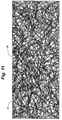
- Figure 8 schematically depicts a 100 percent coverage situation. In this schematic figure, nanotubes below the illustrated tubes are not shown. However, in the areas that appear to be open space in this two-dimensional figure, there would actually be other carbon nanotubes below these spaces (this, however, is not the case for Figure 9 and 10 ) so as to provide 100 percent coverage. In other cases, the nanotubes cover only part of the surface 18.
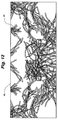
- the coverage can optionally be less than or equal to about 60 percent, less than or equal to about 50 percent, or less than or equal to about 30 percent.
- Figures 9 and 10 schematically depict embodiments where the coverage is less than 60 percent and less than 50 percent, and Figure 10 schematically depicts an embodiment where the coverage is less than 30 percent.
- the nanotubes cover at least about 1-2 percent of the surface 18.
- the coating 50 comprises carbon nanotubes 20 and transparent dielectric film 30.
- the carbon nanotubes 20 can be provided over the surface so as to provide any desired coverage, such as any coverage range noted above.
- the transparent dielectric film 30 is provided over (e.g., so as to embed) at least some of the carbon nanotubes 20.
- the dielectric film 30 is shown entirely over the nanotubes 20. In other cases, the film 30 covers only parts, or some, of the nanotubes. For example, some of the nanotubes may be covered whereas others may project somewhat from the top surface of the film 30.
- the coating here, for example, can have a thickness of less than 10,000 angstroms, less than 4,000 angstroms, or less than 1,500 angstroms.
- Figure 3 illustrates a graded coating 50 comprising both carbon nanotubes 20 and transparent dielectric film 30.
- the graded coating comprises, from the substrate surface 18 outwardly, a generally continuously increasing concentration of transparent dielectric film 30 and a generally continuously decreasing concentration of carbon nanotubes 20.
- the graded coating comprises, from the substrate surface 18 outwardly, a generally continuously increasing concentration of carbon nanotubes 20 and a generally continuously decreasing concentration of transparent dielectric film 30. This could be achieved through methods in which a transparent dielectric film is deposited before (e.g., under) the carbon nanotubes.
- the coating 50 in any of the illustrated embodiments can have a thickness of anywhere between 100 angstroms and 30,000 angstroms, depending on the desired conductivity and transmission properties of the coating. Moreover, some applications may call for even greater thicknesses. The more narrow exemplary thickness ranges noted above may be preferable in embodiments of this disclosure.
- a heat treatment can optionally be performed on the coated substrate. This may involve tempering, heat strengthening, delivering energy to the coated substrate using a pulse of light or a pulse of plasma, etc.
- the coated substrate is by no means required to be heat treated in all embodiments.
- a sheet of soda-lime glass is coated with carbon nanotubes at a coverage of about 30% and a thickness of 100 ⁇ .
- the carbon nanotubes are deposited by spray deposition.
- Synthesized nanotubes (such as tubes obtained commercially from Carbon Solutions, Inc.) are dissolved in a solvent (e.g., water or organic material such as isopropanol).
- a solvent e.g., water or organic material such as isopropanol.
- the nanotubes are functionalized so they will dissolve in the desired solvent.
- a 60-minute treatment in an ultrasonicator in isopropanol, water, or other solvent may be useful.
- the tubes can be suspended in a stable solution using a surfactant, such as sodium dodecyl sulfate (SDS).
- SDS sodium dodecyl sulfate
- the solution can be sprayed (e.g., using an ultrasonic sprayer) onto the sheet of glass so that a coverage of about 30% is obtained.
- the solvent evaporates from the glass sheet, so that primarily the nanotubes remain.
- the glass sheet thus coated with carbon nanotubes on one of its major surfaces is then conveyed through a sputter coater, in which titanium oxide film is sputter deposited over the carbon nanotubes 20 at a theoretical thickness of 40 ⁇ .
- the film can be deposited by sputtering a titanium target in an oxidizing atmosphere or by sputtering a titanium oxide target (such as a substoichiometric titania target) in an inert atmosphere.
- a titanium oxide target such as a substoichiometric titania target
- Useful substoichiometric titania targets can be obtained commercially from Bekaert VDS (Deinze, Belgium). Targets of this nature and useful sputter deposition methods are described in U.S. Patents 6,511,587 , 6,468,402 , and 6,461,682 .
- the invention provides an IG unit having at least one transparent pane bearing a coating comprising carbon nanotubes.
- the coating is on a #1 surface of the unit.
- the coating is on a #4 surface of the unit, or on a #6 surface of the unit.
- the unit can have such coatings on both #1 and #4 surfaces, or on both #1 and #6 surfaces, etc.
- the unit can be a double-pane unit, triple-pane unit, etc.
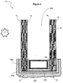
- an IG unit 110 is provided having a first pane 10 and a second pane 10' separated by a between-pane space 800.
- a spacer 900 (which can optionally be an integral part of a sash, frame, etc.) is commonly provided to separate the panes 10 and 10'.
- the IG unit is mounted in a frame 1000 which is mounted in a building 2000, although this is by no means required.
- the spacer can be secured to the inner surfaces of the panes using an adhesive 700.
- an end sealant 600 is also provided.
- the first pane 10 has an outer surface 12 (the #1 surface) and an inner surface 14 (the #2 surface).
- the illustrated second pane 10' has an inner surface 16 (the #3 surface) and an outer surface 18 (the #4 surface).
- the first pane 10 can optionally be an outboard pane.
- the second pane 10 can optionally be an inboard pane, such that its outer surface 18 is a room-side surface (i.e., a surface exposed to an indoor environment).
- the unit can be an advantageous anti-condensation insulating glazing unit.
- the surface 18 (the #4 surface) of the unit bears a coating 50 comprising carbon nanotubes.
- the #6 surface can have such a coating.
- the coating 50 can be any one of the coating embodiments already described with reference to Figures 1-3 .
- the second pane 10' bears the coating 50.
- the first pane 10 can also (or alternatively) bear a coating comprising carbon nanotubes.
- the unit 110 is only provided with a coating 50 comprising carbon nanotubes. That is, only the outer surface 18 of the second pane 10' is provided with a coating 50 while the surfaces 12, 14 and 16 are uncoated.
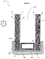
- the IG unit 110 also has a functional coating (e.g., a low-emissivity coating) on another surface (e.g., the #2 surface or #3 surface).
- a functional coating e.g., a low-emissivity coating
- the IG unit 110 has a #2 surface provided with a low-emissivity coating 60 and a #4 surface provided with a coating 50 comprising carbon nanotubes.
- a triple-pane IG unit has a coating comprising carbon nanotubes on a #6 surface in combination with a low-emissivity coating on a #2 surface or a #4 surface (or low-emissivity coatings may be on both the #2 and #4 surfaces).
- the low-emissivity coating 60 can be any such coating known in the art.
- the coating can have one, two, three or more infrared-reflective films.
- Low-emissivity coatings having one or two infrared-reflective films are known in the art. Suitable low-emissivity coatings having three or more infrared-reflective films are described in Applicant's own U.S. Patent Application No. 11/360,266 .
- One particular embodiment group provides a multiple-pane IG unit having one major surface (preferably, a #4 surface or a #6 surface) bearing a coating comprising carbon nanotubes and another major surface bearing a low-emissivity comprising three infrared-reflective film regions (each optionally comprising silver).
- the IG unit also has a major surface (preferably a #1 surface) bearing a low-maintenance coating, such as a hydrophilic and/or photocatalytic coating.
- the low-maintenance coating, the low-emissivity coating, and the coating comprising carbon nanotubes have a combined thickness of less than 10,000 angstroms (e.g., between 1,000 and 10,000 angstroms), perhaps even less than 5,000 angstroms (e.g., between 1,000 angstroms and 5,000 angstroms). This can provide a particularly good combination of functional coating properties while simultaneously producing desirable optics/appearance features.
- the IG unit 110 can be provided with a low-maintenance coating 70 on the exterior surface 12 (the #1 surface).
- the low-maintenance coating can, for example, comprise silica and/or titania. Suitable low-maintenance coatings are described in Applicant's own U.S. Patent Application Nos. 11/021,482 , 11/179,178 , 11/179,852 , 11/129,820 , and 11/293,032 .
- the IG unit 110 has a #1 surface provided with a low-maintenance coating 70, a #2 surface provided with a low-emissivity coating 60 (optionally having one, two, or three silver-containing layers) and a #4 surface provided with a coating 50 comprising carbon nanotubes.
- the low-maintenance coating 70, the low-emissivity coating 60, and the coating 50 comprising carbon nanotubes have a combined physical thickness of less than about 5,000 angstroms, such as between 1,000 angstroms and 5,000 angstroms.
- one embodiment provides a double-pane IG unit having a low-maintenance coating formed by 75 ⁇ of silica film (optionally containing alumina or the like) directly over the #1 surface with 25-40 ⁇ of TiO 2 directly over the silica, a coating formed by carbon nanotubes directly over the #4 surface and having a thickness of 100 ⁇ at 30% coverage and a low-emissivity coating formed by the following sequence of films over the #2 surface: 130 ⁇ of TiO 2 / 120 ⁇ of Ag/ 20 ⁇ of Ti (optionally being at least partially oxidized)/470 ⁇ of TiO 2 /150 ⁇ of Ag/20 ⁇ of Ti (optionally oxidized at least in part)/550 ⁇ of TiO 2 /205 ⁇ of Ag/20 ⁇ of Ti (optionally oxidized at least in part)/280 ⁇ of TiO 2 .
- Figure 7 depicts a triple pane IG unit 110.
- the IG unit 110 is provided having a first pane 10, a second, middle pane 10', and a third pane 10 " .
- the first pane 10 and second pane 10' are separated by a between-pane space 800 and the second pane 10' and the third pane 10" are separated by a between-pane space 800'.
- a spacer 900 (which can optionally be an integral part of a sash, frame, etc.) is commonly provided to separate the panes 10 and 10' and a spacer 900' is provided to separate the panes 10' and 10".
- the spacers can be secured to the inner surfaces of the panes using adhesive 700. In some cases, end sealants 600 are also provided.
- the first pane 10 has an outer surface 12 (the #1 surface) and an inner surface 14 (the #2 surface).
- the illustrated second pane 10 ' has a surface 13 (the #3 surface) and a surface 15 (the #4 surface).
- the illustrated third pane 10" has an inner surface 16 (the #5 surface) and an outer surface 18 (the #6 surface).
- the first pane 10 can optionally be an outboard pane.
- it can be mounted in a frame 1000 (a window frame, door frame, skylight frame, etc.) such that its outer surface 12 is exposed to an outdoor environment.
- the illustrated inner surfaces 14, 13, 15, 16 are exposed to the atmosphere in the between-pane spaces 800, 800' of the IG unit.
- the third pane 10" can optionally be an inboard pane, such that its outer surface 18 is a room-side surface.
- the surface 18 (the #6 surface) of the unit bears a coating 50 comprising carbon nanotubes.
- the coating 50 can be any one of the coating embodiments already described with reference to Figures 1-3 .
- the surface 15 (the #4 surface) bears a low-emissivity coating 60.
- a low-emissivity coating can (additionally or alternatively) be provided on surface 14 (the #2 surface), surface 13 (the #3 surface) or surface 16 (the #5 surface).
- the low-emissivity coating 60 can be any such coating known in the art.
- a low-maintenance coating 70 is also provided on the exterior surface 12 (the #1 surface) in the illustrated embodiment.
- the only coating on the IG unit is the coating 50 on the #6 surface.
- only the coatings 50 and 70 are provided.
- the present coating comprising carbon nanotubes has a number of beneficial properties.
- the ensuing discussion reports several of these properties.
- properties are reported for a double-pane IG unit having the present coating 50 on its #4 surface 18.
- the reported properties are calculated for a double-pane IG unit wherein both panes are clear 2.2 mm soda lime float glass with a 1 ⁇ 2 inch between-pane space filled with an insulative gas mix of 90% argon and 10% air.
- both panes are clear 2.2 mm soda lime float glass with a 1 ⁇ 2 inch between-pane space filled with an insulative gas mix of 90% argon and 10% air.
- the present discussion reflects determinations that can be made using the well known WINDOW 5.2a computer program (e.g., calculating center of glass data) under standard ASHRAE conditions.
- the coating 50 can provide exceptional thermal insulating properties.
- the thickness, nanotube coverage, and composition of the coating 50 are selected such that the coating 50 exhibits a sheet resistance of less than 100 ohms per square, less than 50 ohms per square or less than 20 ohms per square.
- the sheet resistance of the coating can be measured in standard fashion using a 4-point probe. Other methods known in the art as being useful for calculating sheet resistance can also be used.
- the invention provides an IG unit having a U value of less than 0.24 and more preferably less than 0.21.
- the U value of a glazing is a measure of the thermal insulating property of the unit. The smaller the U value, the better the insulating property.
- the term U Value is well known in the art.
- the IG unit can be of the type shown in Figure 4 (having only coating 50), of the type shown in Figure 5 (having both coatings 50 and 60), or of the type shown in Figure 6 (having coatings 50, 60 and 70).
- the thickness, nanotube coverage, and composition of the coating 50 are selected such that providing only this coating 50 on the IG unit results in the unit having a U value within one or more of the ranges noted in this paragraph.
- the IG unit reaches the desired low U value by virtue of the combined effects of two or more coatings, e.g., coatings 50 and 60.
- the coating has a thickness, nanotube coverage, and composition selected to provide the IG unit with a ⁇ U of at least about 0.03.
- the ⁇ U is defined as the absolute value of the difference between the U value of the unit with the coating 50 and the U value of the unit without the coating 50.
- the coating 50 can also have exceptionally low emissivity.
- the emissivity of the coating 50 is less than 0.25.
- the present emissivity values can be determined as specified in "Standard Test Method For Emittance Of Specular Surfaces Using Spectrometric Measurements" NFRC 301-93. Emissivity can be calculated by multiplying the measured sheet resistance by 0.016866. Using this method, a coating 50 that provides sheet resistance of about 1.25, for example, can be determined to have an emissivity of about 0.021.
- the present coating 50 can provide high visible transmission.
- the coating 50 provides a visible transmission (for a monolithic pane or an IG unit) of between 30% and 75%.
- a pane bearing the coating 50 may have a monolithic transmission in this range and/or an IG unit with a pane bearing the coating 50 (optionally also having coatings 60 and/or 70 on the appropriate surface(s)) may have an insulated transmission in this range.
- a monolithic glass pane having on one of its major surfaces a coating formed by carbon nanotubes at a coverage of 50% and a thickness of 50 ⁇ is expected to provide a visible transmission of at least 70%.
- visible transmittance is well known in the art and is used herein in accordance with its well-known meaning. Visible transmittance, as well as visible reflectance, can be determined in accordance with NFRC 300, Standard Test Method for Determining the Solar and Infrared Optical Properties of Glazing Materials and Fading Resistance of Systems (National Fenestration Rating Council Incorporated, adopted December 2001, published January 2002 ). The well known WINDOW 5.2a computer program can be used in calculating these and other reported optical properties.
- the coating 50 has a thickness, nanotube coverage, and composition selected to provide the glazing (e.g., an IG unit) with a ⁇ T v of less than 5%, or even less than 2%.
- the ⁇ T v is defined as the absolute value of the difference between the visible transmittance of the glazing with the coating 50 and the transmittance of the glazing without the coating 50.
- the coating 50 can be provided to impart electrical conductivity and/or strength with a minimal attendant decrease in visible transmission.
- the coating 50 is formed by carbon nanotubes deposited onto the substrate surface at a thickness of about 100 angstroms and having a surface coverage of 30%. A coating according to this embodiment is expected to provide a ⁇ T v of less than 5%.
- the present coating 50 desirably facilitates pleasing color properties.
- the following discussion of transmitted and reflected color is reported using the well known color coordinates of "a" and "b". In particular, these color coordinates are indicated herein using the subscript h (i.e., a h and b h ) to represent the conventional use of the well known Hunter Lab Color System (Hunter methods/units, III. D65, 10 degree observer).
- the present color properties can be determined as specified in ASTM D-2244-93, "Standard Test Method For Calculation Of Color Differences From Instrumentally Measured Color Coordinates", Sep. 15, 1993, as augmented by ASTM E-308-85 Annual Book of ASTM Standards, Vol. 06.01 "Standard Method For Computing The Colors Of Objects By Using The CIE System ".
- the coating 50 desirably provides an IG unit with a pleasing transmitted color. It is commonly desirable for windows to exhibit hues of blue or blue-green, with blue commonly being especially desired.
- the IG unit has a transmitted color characterized by an a h color coordinate of between 0 and - 6 and a b h color coordinate of between + 6 and - 6.
- One exemplary embodiment of this nature involves a double-pane IG unit where the #4 surface has a coating formed by carbon nanotubes at 50% coverage and an average thickness of 50 ⁇ , and the #2 surface has a low-emissivity coating formed by the following sequence of films, moving outwardly from the #2 surface: 165 ⁇ of zinc tin oxide/120 ⁇ of Ag/20 ⁇ of Ti (optionally being at least partially oxidized/590 ⁇ of zinc tin oxide/155 ⁇ of Ag/20 ⁇ of Ti (optionally being at least partially oxidized)/665 ⁇ of zinc tin oxide, 205 ⁇ of Ag/20 ⁇ of Ti (optionally being at least partially oxidized)/315 ⁇ of zinc tin oxide (the outermost 100 ⁇ of zinc tin oxide can optionally be replaced with 100 ⁇ of silicon nitride).
- the coating 50 desirably provides an IG unit with a reflected color that is pleasing.
- the reflected color reported herein is measured from the #1 surface of the IG unit.
- the coating is on an IG unit having an exterior reflected color characterized by an a h color coordinate of between + 2 and - 6 and a b h color coordinate of between + 6 and - 6.
- the exemplary embodiment detailed in the paragraph immediately above would be useful.
Landscapes
- Chemical & Material Sciences (AREA)
- Engineering & Computer Science (AREA)
- General Chemical & Material Sciences (AREA)
- Organic Chemistry (AREA)
- Materials Engineering (AREA)
- Geochemistry & Mineralogy (AREA)
- Life Sciences & Earth Sciences (AREA)
- Chemical Kinetics & Catalysis (AREA)
- Dispersion Chemistry (AREA)
- Composite Materials (AREA)
- Structural Engineering (AREA)
- Civil Engineering (AREA)
- Laminated Bodies (AREA)
- Surface Treatment Of Glass (AREA)
- Joining Of Glass To Other Materials (AREA)
- Carbon And Carbon Compounds (AREA)
- Non-Insulated Conductors (AREA)
Description
- The present invention provides an insulating glazing unit having a coating including carbon nanotubes.
- Glass sheets and other substrates can be coated with a stack of transparent, metal-containing films to vary the optical properties of the coated substrates. Particularly desirable are coatings characterized by their ability to readily transmit visible light while minimizing the transmittance of other wavelengths of radiation, especially radiation in the infrared spectrum. Known coatings that reflect infrared radiation include low-emissivity coatings and also transparent conductor coatings, such as indium tin oxide ("ITO") coatings. These coatings are useful for reducing radiant heat transfer without impairing visible transmittance. Coated glass of this nature is useful as architectural glass and as automotive glass.
- Coated glass sheets are often incorporated into glazings. At least three types of glazings are commercially available today. These three types are often referred to as single glazing, double glazing and triple glazing. Double glazings are the most common. They commonly include an insulating glazing unit ("IG unit") having a sealed space between two panes of glass. Coating on the glass imparts desirable optical properties into the glazing.
- It is challenging to provide a glazing that exhibits a well balanced set of properties. For example, when a glazing includes a glass sheet bearing a coating, such as a low-emissivity coating, it is challenging to achieve a desired level of visible transmittance, low visible reflectance, good thermal insulating properties, neutral color, and good durability. In particular, it is difficult to identify specific combinations of film thicknesses and compositions that achieve an exceptional balance of coating properties. To achieve exceptional results for a particular property, one may consider a variety of potential coating adjustments. Many adjustments, however, adversely impact other desired coating properties.
- It is also challenging to provide coated glass that can be produced in a cost-effective manner. For example, transparent conductor coatings, such as ITO coatings, can be expensive to produce. Materials for producing ITO coatings are also limited in supply. As a result, there is a need for an alternate transparent conductor coating in the marketplace. ITO coatings also may have less than desirable durability. For example, ITO coatings may be relatively prone to scratching. Thus, there is a need for a transparent conductor coating that can be produced in a cost-effective manner and also is durable.
- Desirable properties are even more difficult to achieve when coatings are subjected to heat treatment. It is often necessary to heat coated glass sheets to temperatures at or near the melting point of glass to temper the glass or to enable it to be bent into desired shapes, such as curved automobile windshields. Tempering is important for glass in automobile windows, and particularly for glass in automobile windshields. Upon breaking, tempered glass desirably exhibits a break pattern in which the glass shatters into a great many small pieces, rather than into large dangerous shards. During tempering, coated glass is typically subjected to elevated temperatures on the order of 700 degrees C. Moreover, coated glass often must be able to withstand such temperatures for substantial periods of time. Certain coatings, for example ITO coatings, may not withstand such high temperature processing without some deterioration. Thus, there is a need for a transparent conductor coating that can withstand high temperature processing.
- According to the present invention, there is provided a multiple-pane insulating glazing unit including at least two spaced-apart panes, the insulating glazing unit having at least one between-pane space and having a desired surface on which there is provided a transparent conductor coating comprising carbon nanotubes and inorganic material, the desired surface being an exterior surface of the unit rather than being an interior surface facing a between-pane space of the unit.
- The transparent conductor coating can have a thickness, nanotube coverage, and composition selected to provide the unit with a ΔU of at least 0.03, the ΔU being defined as an absolute value of a difference between the U value of the unit with the transparent conductor coating and the U value of the unit without the transparent conductor coating. In certain cases, the U value is of less than 0.24 or less than 0.21. The transparent conductor coating can provide an emissivity of less than 0.25. In some cases, the transparent conductor coating has a thickness, nanotube coverage, and composition selected to provide a ΔTv, of less than 5%, the ΔTv being defined as an absolute value of a difference between visible transmittance of the unit with the transparent conductor coating and visible transmittance of the unit without the transparent conductor coating.
- In some cases, the insulating glazing unit has a visible transmission between 30% and 75%. The unit can also have a #2 surface on which there is provided a low-emissivity coating. In certain cases, the low-emissivity coating comprises at least one infrared-reflective film comprising silver, said infrared-reflective film being located between two transparent dielectric films. The unit can also have a #1 surface on which there is provided a water-sheeting coating. The water-sheeting coating, for example, can comprise silica, titania, or both. The transparent conductor coating, the low-emissivity coating, and the water-sheeting coating (when all three such coatings are provided) can have a combined physical thickness of between 1,000 angstroms and 10,000 angstroms, such as 1,000 angstroms and 5,000 angstroms. In some embodiments, the insulating glazing unit has an exterior reflected color characterized by an ah color coordinate of between + 2 and - 6 and a bh color coordinate of between + 6 and - 6. Likewise, in some embodiments, the insulating glazing unit has a transmitted color characterized by an ah color coordinate of between 0 and - 6 and a bh color coordinate of between + 6 and -6.
- A glazing is also provided comprising a transparent pane having a major surface on which there is provided a coating comprising carbon nanotubes, the coating comprising both transparent dielectric film and the carbon nanotubes, wherein the coating has a thickness of greater than 200 angstroms and less than 4,000 angstroms. The major surface of the pane can have a total surface area of which the carbon nanotubes cover less than 50 percent or less than 30 percent of the total surface area of the major surface. The coating can have a surface resistance of less than 100 ohms per square or less than 20 ohms per square. The transparent dielectric film can be a metal oxide film and can be over at least some of the carbon nanotubes.
- A glazing is also provided comprising a transparent pane on which there is provided a coating comprising carbon nanotubes, the coating having a thickness of less than 4,000 angstroms, wherein the coating is located on a major surface of the transparent pane and wherein the carbon nanotubes provide coverage over at least 1-2 percent of the major surface. The coated transparent pane can have a monolithic transmission of at least 70 percent. The coating can have a thickness of less than 1,500 angstroms and a surface resistance of less than 100 ohms per square. The nanotube coverage can be provided at 100 percent. In some cases, the glazing includes a further pane on which there is provided a coating comprising three infrared-reflective films each comprising silver.
- Certain embodiments provide a glazing comprising a transparent pane with a major surface on which there is provided a coating consisting essentially of dielectric film and carbon nanotubes. In the present embodiments, the coating has a thickness of less than 10,000 angstroms, and the coating has a dielectric/carbon nanotube weight ratio of between 2.3 and 9999. The dielectric/carbon nanotube weight ratio is defined as the total weight of the dielectric film over the total weight of the carbon nanotubes.
- An insulating glazing unit is also provided, the unit being mounted in a frame on a wall of a building, the unit having a #1 surface exposed to an outdoor environment and a #2 surface exposed to a between-pane space of the unit, wherein the unit has an inboard pane with a room-side surface exposed to an indoor environment of the building, wherein a coating comprising carbon nanotubes is on the room-side surface, wherein the carbon nanotubes cover less than 100% of the room-side surface, and wherein the coating includes a transparent dielectric film over the carbon nanotubes. The coating comprising carbon nanotubes can have a thickness of less than 4,000 angstroms or less than 1,500 angstroms. The carbon nanotubes can cover less than 50 percent or less than 30 percent of the room-side surface.
- An insulating glazing unit is also provided, the unit being mounted in a frame on a wall of a building is provided, the unit having a #1 surface exposed to an outdoor environment, wherein a water-sheeting coating is on the #1 surface, the unit having an inboard pane with a room-side surface exposed to an indoor environment of the building, wherein the coating comprising carbon nanotubes is on the room-side surface, and wherein the unit has an inner surface that is coated and is exposed to a between-pane space of the unit, wherein a low-emissivity coating is on said inner surface, and wherein the coating comprising carbon nanotubes, the low-emissivity coating, and the water-sheeting coating have a combined thickness of between 1,000 angstroms and 10,000 angstroms such as between 1,000 angstroms and 5,000 angstroms.
-
-
Figure 1 is a schematic cross-sectional view of a substrate having a surface bearing a coating; -
Figure 2 is a schematic cross-sectional view of a substrate having a surface bearing a coating; -
Figure 3 is a schematic cross-sectional view of a substrate having a surface bearing a coating; -
Figure 4 is a partially broken-away schematic cross-sectional side view of a multiple-pane insulating glazing unit that is mounted in a frame on a wall of a building in accordance with certain embodiments of the invention; -
Figure 5 is a partially broken-away schematic cross-sectional side view of a multiple-pane insulating glazing unit that is mounted in a frame on a wall of a building in accordance with certain embodiments of the invention; -
Figure 6 is a partially broken-away schematic cross-sectional side view of a multiple-pane insulating glazing unit that is mounted in a frame on a wall of a building in accordance with certain embodiments of the invention; -
Figure 7 is a partially broken-away schematic cross-sectional side view of a multiple-pane insulating glazing unit that is mounted in a frame on a wall of a building in accordance with certain embodiments of the invention; -
Figure 8 is a schematic magnified top image of a surface bearing a coating comprising carbon nanotubes; -
Figure 9 is another schematic magnified top image of a surface bearing a coating comprising carbon nanotubes; and -
Figure 10 is yet another schematic magnified top image of a surface bearing a coating comprising carbon nanotubes. - The following detailed description is to be read with reference to the drawings, in which like elements in different drawings have like reference numbers. The drawings, which are not necessarily to scale, depict selected embodiments and are not intended to limit the scope of the invention. Skilled artisans will recognize that the given examples have many alternatives that fall within the scope of the invention.
- In one embodiment, a glazing unit includes a sheet-
like substrate 10, 10' having generally opposed first 12, 16 and second 14, 18 major surfaces. - For many applications, the substrate will comprise a transparent (or at least translucent) material, such as glass or clear plastic. A variety of known glass types can be used, and soda-lime glass will commonly be preferred. In certain preferred embodiments, the substrate is part of a window, skylight, door, shower door, or other glazing. Substrates of various sizes can be used in the present invention. Commonly, large-area substrates are used. Certain embodiments involve a
substrate 10 having a major dimension (e.g., a length or width) of at least .5 meter, preferably at least 1 meter, perhaps more preferably at least 1.5 meters (e.g., between 2 meters and 4 meters), and in some cases at least 3 meters. In some embodiments, the substrate is a jumbo glass sheet having a length and/or width that is between 3 meters and 10 meters, e.g., a glass sheet having a width of 3.5 meters and a length of 6.5 meters. Substrates having a length and/or width of greater than 10 meters are also anticipated. - In some embodiments, the substrate 10' is a generally square or rectangular glass sheet. The substrate in these embodiments can have any of the dimensions described in the preceding paragraph and/or in the following paragraph. In one particular embodiment, the substrate is a generally rectangular glass sheet having a width of between 3 meters and 5 meters, such as 3.5 meters, and a length of between 6 meters and 10 meters, such as 6.5 meters.
- Substrates of various thicknesses can be used in the present invention. In some embodiments, the substrate 10' (which can optionally be a glass sheet) has a thickness of 1-5 mm. Certain embodiments involve a substrate 10' with a thickness of between 2.3 mm and 4.8 mm, and perhaps more preferably between 2.5 mm and 4.8 mm. In one particular embodiment, a sheet of glass (e.g., soda-lime glass) with a thickness of 3 mm is used. In one group of embodiments, the thickness of the substrate (which can be glass, plastic, or another material) is between 4 mm and 20 mm. Thicknesses in this range, for example, may be useful for aquarium tanks (in which case, the substrate can optionally be glass or acrylic). When the substrate is float glass, it will commonly have a thickness of between 4 mm and 19 mm. In another group of embodiments, the substrate is a thin sheet (e.g., of glass) having a thickness of between 0.35 mm and 1.9 mm. Embodiments of this nature can optionally involve the substrate 10' being a sheet of display glass or the like.
- The invention provides a glazing comprising a substrate, e.g., a transparent pane, on which there is provided a coating comprising carbon nanotubes. The glazing, for example, can be double glazing, or triple glazing. In some cases, the glazing is a double glazed window, door, skylight, etc. The glazing will comprise an insulating glazing unit. Commonly, the insulating glazing unit includes two transparent panes (optionally of glass) bounding a between-pane space. The between-pane space provides thermal insulation, and this insulating effect can optionally be enhanced by filling the space with an insulative gas such as argon or krypton.
- A transparent pane of the glazing bears a coating comprising carbon nanotubes. The carbon nanotubes can be of any kind known in the art. Generally speaking, carbon nanotubes are cylindrical carbon molecules that exhibit extraordinary strength, electrical and conductive properties. Carbon nanotubes are of two types: single-walled and multi-walled. A single-walled nanotube consists of a single cylinder whereas a multi-walled nanotubes comprises several concentric cylinders. A nanotube is often on the order of a few nanometers in diameter and up to several centimeters in length (e.g., between 100 nm and 700 cm, such as between hundreds of nanometers and several centimeters). In some embodiments, the present coating comprises a plurality of carbon nanotubes having an average length of greater ;than 500 nm, such as between 500 nm and 5 cm, and perhaps preferably between 5 microns and 5 cm. In some cases, a majority (optionally substantially all) of the carbon nanotubes are of lengths falling in one or more of the ranges noted in this paragraph. The coating can, in addition to the carbon nanotubes, include other carbon forms or other materials, such as materials that end up in the coating as by-products of the nanotube deposition or synthesis process. For example, metallic catalysts are often used to synthesize nanotubes and can end up in the coating as a byproduct.
- The coating comprising carbon nanotubes imparts several desirable properties to the glazing. Carbon nanotubes are excellent thermal and electrical conductors along the axis of each tube, and good thermal insulators perpendicular to the tube axis. As a result, they can provide the glazing with low sheet resistance and low-emissivity. Thus, the coating can serve as a transparent conductor coating. Carbon nanotube coatings are also extremely durable to heat processing. Thus, they may be particularly durable to many processing methods, such as glass tempering and other elevated temperature processes. In particular, they are expected to be more durable than ITO transparent conductor coatings.
- A coating containing carbon nanotubes is disclosed for example in
JP 2004 075400 - In some cases, the coating (or at least a layer or region of the coating) comprises both carbon nanotubes and polymeric film. The polymeric film is an electrically conductive polymeric film in some cases and is used to protect (optionally over at least some of, over substantially all of, or over all of) the nanotubes. In certain embodiments, the polymeric film comprises a polyaniline polymer. For example, in some embodiments, the film comprises polyether urethane 4901, a material commercially available from Hi Tech Polymers, a company located in Cleveland, Ohio, USA.
- The coating can comprise both carbon nanotubes and transparent dielectric film. Some embodiments of this nature provide carbon nanotubes disposed in a ceramic matrix (e.g., a matrix of a transparent dielectric material, such as a metal oxide). The transparent dielectric film can include titanium oxide, titanium nitride, silicon oxide, silicon nitride, zinc oxide, tin oxide and/or others. The transparent dielectric component of the coating consists essentially of an inorganic material selected from the group consisting of metal oxides, metal nitrides, and metal oxynitrides.
- When combined with a dielectric film, the carbon nanotubes alter the properties of the dielectric film. For example, the nanotubes can be provided to increase roughness (and surface area), hardness, conductivity and/or other properties of the dielectric film. In one embodiment, the
coating 50 comprises (and optionally consists essentially of) titanium oxide (e.g., TiO2) and carbon nanotubes. Here, the titanium oxide can optionally be a film deposited over a layer of carbon nanotubes. The resulting coating may have a particularly high level of photoactivity due to increased roughness/surface area created by the carbon nanotubes. The nanotubes may also impart particularly low sheet resistance and/or high strength to the coated substrate. In some cases, the thus coated substrate is subjected to a post deposition heat treatment, such as tempering, heat strengthening, or another heat treatment that impacts the properties of the coating. In these cases, the coating may include both crystalline titania and the carbon nanotubes. - In some embodiments, the
coating 50 has a particular dielectric/carbon nanotube weight ratio. The ratio, for example, can be about 2.3-9999 (e.g., about 2.3-999), or perhaps 9-9999 (e.g., about 9-999). The dielectric/carbon nanotube weight ratio is defined as the total weight of the dielectric material over the total weight of the carbon nanotubes. These ranges are examples: depending on the application, it may be desirable to vary the ratio. For example, a lower ratio may be desirable for electromagnetic shielding embodiments, while a higher ratio may be selected when particularly high visible transmission is desired. - When provided, the dielectric film can increase the durability of the coating. In some cases, the coating includes both carbon nanotubes and silica. In other cases, the coating includes both carbon nanotubes and silicon nitride (or silicon oxynitride). The silicon oxynitride embodiment, for example, can be varied (e.g., in terms of the relative amounts of oxide and nitride) so as to achieve different levels of refractive index. These embodiments may be preferred, for example, when it is desired to employ an amorphous or substantially amorphous dielectric film in combination with carbon nanotubes, as may be provided in a broader group of embodiments.
- Thus, one group of embodiments provides a coating comprising (optionally consisting essentially of) carbon nanotubes and amorphous or substantially amorphous dielectric film. The carbon nanotubes, for example, may be embedded in a matrix of amorphous or substantially amorphous dielectric material. The dielectric material, for example, can be selected from the group consisting of silica, silicon nitride, and silicon oxynitride. One embodiment provides the amorphous dielectric film over the carbon nanotubes (optionally so as to entirely encase the carbon nanotubes), e.g., for durability purposes.
- The
coating 50 in certain embodiments is subjected to tempering, heat strengthening, a pulse of light, a pulse of plasma, or another heat treatment. Some of the present embodiments involve heat treating the carbon nanotube-containing coating (e.g., to a temperature exceeding 300 degrees C, or even exceeding 600 degrees C) while the coating is exposed to an oxidizing atmosphere (e.g., air). Some embodiments provide a coating in the form of one or more films that are durable to such heat treatment in that the coating remains transparent, rather than browning or otherwise turning opaque in response to such heat treatment. The coating in these embodiments, for example, can advantageously consist essentially of carbon nanotubes and inorganic material (optionally selected from metal oxides, metal nitrides, and metal oxynitrides). - In one subgroup of the dielectric-carbon nanotube coating embodiments, the coating comprises electrically non-conductive dielectric material. For example, this may involve using TiO2, SiO2, or various mixtures of TiO2 and SiO2, to name just a few. The dielectric component of the
coating 50 can optionally consist essentially of electrically non-conductive dielectric material. - In certain embodiments, the coating has a thickness of less than 4,000 angstroms. In some embodiments of this nature, the
coating 50 has a thickness in the range of between 200 and 4,000 angstroms. The coating in some cases is less than 1,500 angstroms (perhaps even less than 1,000 angstroms). In another group of embodiments, though, the coating has a thickness of between 4,000 and 10,000 angstroms, such as 6,000-7,000 angstroms. More generally then, the thickness may range between 200 and 10,000 angstroms. The thickness ranges noted in this paragraph can be used for any embodiment of the present disclosure. - The carbon nanotubes can be provided on the substrate using a number of known methods. Methods of synthesizing nanotubes include, but are not limited to, arc discharge, laser ablation, chemical vapor deposition, plasma enhanced chemical vapor deposition, pyrolytic deposition, and electrophoresis deposition. Once the carbon nanotubes are synthesized or otherwise obtained, they can be deposited on the substrate. Exemplary deposition methods include spray deposition, ink-jet printing, dispensing, spin-coating, brushing, dipping, and screen-printing. In certain embodiments, the carbon nanotubes are deposited using chemical vapor deposition. Suitable chemical vapor deposition methods for depositing nanotubes are described in
U.S. Patent Application Nos. 09/556,816 and10/945,814 U.S. Patent Application Nos. 10/984,079 , and10/468,145 - Once the carbon nanotubes are provided on a substrate, a dielectric film is optionally deposited over the nanotubes. The dielectric film can be deposited using known methods including, but not limited to, sputtering, chemical vapor deposition, pyrolytic deposition, evaporation, sol-gel deposition, and ion-assisted deposition. In certain embodiments, the dielectric film is deposited by sputtering, such as DC, AC and/or pulsed DC sputtering. One preferred method utilizes DC magnetron sputtering, which is commonly used in the industry and one embodiment of which is described in Chapin's
U.S. Patent 4,166,018 . - In some embodiments, a dielectric film is deposited over a substrate previously coated with carbon nanotubes by transporting the substrate through a sputter coater in which the dielectric film is applied. The sputter coater includes one or more targets that can be sputtered to deposit the dielectric film. In some cases, the coater is equipped with a plurality of targets carrying sputterable material formed of a dielectric (e.g., zinc aluminum oxide or titanium dioxide, optionally sub-oxides thereof). The target may be sputtered in an inert atmosphere (e.g., an argon atmosphere), or in a slightly oxidizing atmosphere, or in a slightly nitriding atmosphere, to deposit the desired dielectric material on the substrate. More commonly, though, a metallic target is provided and the dielectric film is deposited by sputtering a metal target in a reactive atmosphere. The metal reacts with the reactive gas (e.g., oxygen and/or nitrogen) in the atmosphere to form a dielectric. For example, a zinc oxide film can be deposited by sputtering a zinc target in an oxidizing atmosphere. Likewise, a titanium oxide film can be deposited by sputtering a titanium target in an oxidizing atmosphere. Also, a silicon nitride film can be deposited by sputtering a silicon target (which may be doped with aluminum or the like to improve conductivity) in a nitrogen atmosphere. A silica film can be deposited by sputtering a silicon target (or a Si-Al target) in an oxidizing atmosphere. A series of the desired targets, of course, would normally be used. The thickness of the film thus deposited can be controlled by varying the speed of the substrate and/or by varying the power and sputtering rate of each individual target. Certain preferable methods of sputter depositing dielectric films are described in Applicant's own
U.S. Patent No. 5,318,685 and Patent Application Nos.09/024,240 09/759,661 09/044,681 09/966,636 10/032,901 10/008,949 -
Figures 1-3 each illustrate a substrate 10' having asurface 18 bearing acoating 50 in accordance with different embodiments. Thecoating 50, for example, can be a transparent conductor coating, although this is by no means required. - In
Figure 1 , thecoating 50 consists essentially of carbon nanotubes.Carbon nanotubes 20 are provided over (optionally directly over) thesurface 18. Further, the carbon nanotubes here are exposed (i.e., they define the outermost portion of the coating). In some cases, the nanotubes cover substantially theentire surface 18.Figure 8 schematically depicts a 100 percent coverage situation. In this schematic figure, nanotubes below the illustrated tubes are not shown. However, in the areas that appear to be open space in this two-dimensional figure, there would actually be other carbon nanotubes below these spaces (this, however, is not the case forFigure 9 and 10 ) so as to provide 100 percent coverage. In other cases, the nanotubes cover only part of thesurface 18. For example, the coverage can optionally be less than or equal to about 60 percent, less than or equal to about 50 percent, or less than or equal to about 30 percent.Figures 9 and 10 schematically depict embodiments where the coverage is less than 60 percent and less than 50 percent, andFigure 10 schematically depicts an embodiment where the coverage is less than 30 percent. Preferably, the nanotubes cover at least about 1-2 percent of thesurface 18. - In
Figure 2 , thecoating 50 comprisescarbon nanotubes 20 andtransparent dielectric film 30. Thecarbon nanotubes 20 can be provided over the surface so as to provide any desired coverage, such as any coverage range noted above. Preferably, thetransparent dielectric film 30 is provided over (e.g., so as to embed) at least some of thecarbon nanotubes 20. Thedielectric film 30 is shown entirely over thenanotubes 20. In other cases, thefilm 30 covers only parts, or some, of the nanotubes. For example, some of the nanotubes may be covered whereas others may project somewhat from the top surface of thefilm 30. The coating here, for example, can have a thickness of less than 10,000 angstroms, less than 4,000 angstroms, or less than 1,500 angstroms. -
Figure 3 illustrates a gradedcoating 50 comprising bothcarbon nanotubes 20 andtransparent dielectric film 30. In certain cases, the graded coating comprises, from thesubstrate surface 18 outwardly, a generally continuously increasing concentration oftransparent dielectric film 30 and a generally continuously decreasing concentration ofcarbon nanotubes 20. In other cases, the graded coating comprises, from thesubstrate surface 18 outwardly, a generally continuously increasing concentration ofcarbon nanotubes 20 and a generally continuously decreasing concentration oftransparent dielectric film 30. This could be achieved through methods in which a transparent dielectric film is deposited before (e.g., under) the carbon nanotubes. - The
coating 50 in any of the illustrated embodiments can have a thickness of anywhere between 100 angstroms and 30,000 angstroms, depending on the desired conductivity and transmission properties of the coating. Moreover, some applications may call for even greater thicknesses. The more narrow exemplary thickness ranges noted above may be preferable in embodiments of this disclosure. - Once the substrate is coated, a heat treatment can optionally be performed on the coated substrate. This may involve tempering, heat strengthening, delivering energy to the coated substrate using a pulse of light or a pulse of plasma, etc. The coated substrate, though, is by no means required to be heat treated in all embodiments.
- In one particular embodiment, a sheet of soda-lime glass is coated with carbon nanotubes at a coverage of about 30% and a thickness of 100 Å. The carbon nanotubes are deposited by spray deposition. Synthesized nanotubes (such as tubes obtained commercially from Carbon Solutions, Inc.) are dissolved in a solvent (e.g., water or organic material such as isopropanol). In some cases, the nanotubes are functionalized so they will dissolve in the desired solvent. A 60-minute treatment in an ultrasonicator in isopropanol, water, or other solvent may be useful. In other cases, the tubes can be suspended in a stable solution using a surfactant, such as sodium dodecyl sulfate (SDS). The solution can be sprayed (e.g., using an ultrasonic sprayer) onto the sheet of glass so that a coverage of about 30% is obtained. In many cases, the solvent evaporates from the glass sheet, so that primarily the nanotubes remain. In certain cases, it may be desirable to heat the substrate to increase the rate of solvent evaporation. The glass sheet thus coated with carbon nanotubes on one of its major surfaces is then conveyed through a sputter coater, in which titanium oxide film is sputter deposited over the
carbon nanotubes 20 at a theoretical thickness of 40 Å. The film can be deposited by sputtering a titanium target in an oxidizing atmosphere or by sputtering a titanium oxide target (such as a substoichiometric titania target) in an inert atmosphere. Useful substoichiometric titania targets can be obtained commercially from Bekaert VDS (Deinze, Belgium). Targets of this nature and useful sputter deposition methods are described inU.S. Patents 6,511,587 ,6,468,402 , and6,461,682 . - The invention provides an IG unit having at least one transparent pane bearing a coating comprising carbon nanotubes. In some cases, the coating is on a #1 surface of the unit. In other cases, the coating is on a #4 surface of the unit, or on a #6 surface of the unit. Still further, the unit can have such coatings on both #1 and #4 surfaces, or on both #1 and #6 surfaces, etc. Thus, the unit can be a double-pane unit, triple-pane unit, etc. With reference to
Figures 4-6 , in certain embodiments, anIG unit 110 is provided having afirst pane 10 and a second pane 10' separated by a between-pane space 800. A spacer 900 (which can optionally be an integral part of a sash, frame, etc.) is commonly provided to separate thepanes 10 and 10'. In the illustrated embodiments, the IG unit is mounted in aframe 1000 which is mounted in abuilding 2000, although this is by no means required. The spacer can be secured to the inner surfaces of the panes using an adhesive 700. In some cases, anend sealant 600 is also provided. In the illustrated embodiment, thefirst pane 10 has an outer surface 12 (the #1 surface) and an inner surface 14 (the #2 surface). The illustrated second pane 10' has an inner surface 16 (the #3 surface) and an outer surface 18 (the #4 surface). Thefirst pane 10 can optionally be an outboard pane. For example, it can be mounted in a frame 1000 (a window frame, door frame, skylight frame, etc.) such that itsouter surface 12 is exposed to an outdoor environment. The illustratedinner surfaces pane space 800 of the IG unit. Thesecond pane 10 can optionally be an inboard pane, such that itsouter surface 18 is a room-side surface (i.e., a surface exposed to an indoor environment). - For embodiments where the
coating 50 is on the #1 surface of an IG unit, the unit can be an advantageous anti-condensation insulating glazing unit. - In
Figures 4-6 , the surface 18 (the #4 surface) of the unit bears acoating 50 comprising carbon nanotubes. In some embodiments involving triple glazing, the #6 surface can have such a coating. Thecoating 50 can be any one of the coating embodiments already described with reference toFigures 1-3 . In the illustrated embodiments, the second pane 10' bears thecoating 50. However, thefirst pane 10 can also (or alternatively) bear a coating comprising carbon nanotubes. In the embodiment ofFigure 4 , theunit 110 is only provided with acoating 50 comprising carbon nanotubes. That is, only theouter surface 18 of the second pane 10' is provided with acoating 50 while thesurfaces - In other cases, the
IG unit 110 also has a functional coating (e.g., a low-emissivity coating) on another surface (e.g., the #2 surface or #3 surface). In the embodiment illustrated inFigure 5 , theIG unit 110 has a #2 surface provided with a low-emissivity coating 60 and a #4 surface provided with acoating 50 comprising carbon nanotubes. In another embodiment (as illustrated inFigure 7 ), a triple-pane IG unit has a coating comprising carbon nanotubes on a #6 surface in combination with a low-emissivity coating on a #2 surface or a #4 surface (or low-emissivity coatings may be on both the #2 and #4 surfaces). The low-emissivity coating 60 can be any such coating known in the art. The coating can have one, two, three or more infrared-reflective films. Low-emissivity coatings having one or two infrared-reflective films are known in the art. Suitable low-emissivity coatings having three or more infrared-reflective films are described in Applicant's ownU.S. Patent Application No. 11/360,266 . - One particular embodiment group provides a multiple-pane IG unit having one major surface (preferably, a #4 surface or a #6 surface) bearing a coating comprising carbon nanotubes and another major surface bearing a low-emissivity comprising three infrared-reflective film regions (each optionally comprising silver). In some embodiments of this nature, the IG unit also has a major surface (preferably a #1 surface) bearing a low-maintenance coating, such as a hydrophilic and/or photocatalytic coating. In one particular embodiment, the low-maintenance coating, the low-emissivity coating, and the coating comprising carbon nanotubes have a combined thickness of less than 10,000 angstroms (e.g., between 1,000 and 10,000 angstroms), perhaps even less than 5,000 angstroms (e.g., between 1,000 angstroms and 5,000 angstroms). This can provide a particularly good combination of functional coating properties while simultaneously producing desirable optics/appearance features.
- With reference to
Figure 6 , theIG unit 110 can be provided with a low-maintenance coating 70 on the exterior surface 12 (the #1 surface). The low-maintenance coating can, for example, comprise silica and/or titania. Suitable low-maintenance coatings are described in Applicant's ownU.S. Patent Application Nos. 11/021,482 ,11/179,178 11/179,852 11/129,820 11/293,032 IG unit 110 has a #1 surface provided with a low-maintenance coating 70, a #2 surface provided with a low-emissivity coating 60 (optionally having one, two, or three silver-containing layers) and a #4 surface provided with acoating 50 comprising carbon nanotubes. In some cases, the low-maintenance coating 70, the low-emissivity coating 60, and thecoating 50 comprising carbon nanotubes have a combined physical thickness of less than about 5,000 angstroms, such as between 1,000 angstroms and 5,000 angstroms. For example, one embodiment provides a double-pane IG unit having a low-maintenance coating formed by 75 Å of silica film (optionally containing alumina or the like) directly over the #1 surface with 25-40 Å of TiO2 directly over the silica, a coating formed by carbon nanotubes directly over the #4 surface and having a thickness of 100 Å at 30% coverage and a low-emissivity coating formed by the following sequence of films over the #2 surface: 130 Å of TiO2/ 120 Å of Ag/ 20 Å of Ti (optionally being at least partially oxidized)/470 Å of TiO2/150 Å of Ag/20 Å of Ti (optionally oxidized at least in part)/550 Å of TiO2/205 Å of Ag/20 Å of Ti (optionally oxidized at least in part)/280 Å of TiO2. -
Figure 7 depicts a triplepane IG unit 110. Here, theIG unit 110 is provided having afirst pane 10, a second, middle pane 10', and athird pane 10". Thefirst pane 10 and second pane 10' are separated by a between-pane space 800 and the second pane 10' and thethird pane 10" are separated by a between-pane space 800'. A spacer 900 (which can optionally be an integral part of a sash, frame, etc.) is commonly provided to separate thepanes 10 and 10' and a spacer 900' is provided to separate thepanes 10' and 10". The spacers can be secured to the inner surfaces of the panes using adhesive 700. In some cases,end sealants 600 are also provided. In the illustrated embodiment, thefirst pane 10 has an outer surface 12 (the #1 surface) and an inner surface 14 (the #2 surface). The illustrated second pane 10' has a surface 13 (the #3 surface) and a surface 15 (the #4 surface). The illustratedthird pane 10" has an inner surface 16 (the #5 surface) and an outer surface 18 (the #6 surface). Thefirst pane 10 can optionally be an outboard pane. For example, it can be mounted in a frame 1000 (a window frame, door frame, skylight frame, etc.) such that itsouter surface 12 is exposed to an outdoor environment. The illustratedinner surfaces pane spaces 800, 800' of the IG unit. Thethird pane 10" can optionally be an inboard pane, such that itsouter surface 18 is a room-side surface. - With continued reference to
Figure 7 , the surface 18 (the #6 surface) of the unit bears acoating 50 comprising carbon nanotubes. Thecoating 50 can be any one of the coating embodiments already described with reference toFigures 1-3 . The surface 15 (the #4 surface) bears a low-emissivity coating 60. Of course, a low-emissivity coating can (additionally or alternatively) be provided on surface 14 (the #2 surface), surface 13 (the #3 surface) or surface 16 (the #5 surface). The low-emissivity coating 60 can be any such coating known in the art. A low-maintenance coating 70 is also provided on the exterior surface 12 (the #1 surface) in the illustrated embodiment. In one variant, the only coating on the IG unit is thecoating 50 on the #6 surface. In another variant, only thecoatings - The present coating comprising carbon nanotubes has a number of beneficial properties. The ensuing discussion reports several of these properties. In some cases, properties are reported for a double-pane IG unit having the
present coating 50 on its #4surface 18. In such cases, the reported properties are calculated for a double-pane IG unit wherein both panes are clear 2.2 mm soda lime float glass with a ½ inch between-pane space filled with an insulative gas mix of 90% argon and 10% air. Of course, these specifics are by no means limiting to the invention. Absent an express statement to the contrary, the present discussion reflects determinations that can be made using the well known WINDOW 5.2a computer program (e.g., calculating center of glass data) under standard ASHRAE conditions. - Due to the electrical conductivity of the carbon nanotubes, the
coating 50 can provide exceptional thermal insulating properties. In some embodiments, the thickness, nanotube coverage, and composition of thecoating 50 are selected such that thecoating 50 exhibits a sheet resistance of less than 100 ohms per square, less than 50 ohms per square or less than 20 ohms per square. The sheet resistance of the coating can be measured in standard fashion using a 4-point probe. Other methods known in the art as being useful for calculating sheet resistance can also be used. - In certain embodiments, the invention provides an IG unit having a U value of less than 0.24 and more preferably less than 0.21. As is well known, the U value of a glazing is a measure of the thermal insulating property of the unit. The smaller the U value, the better the insulating property. The term U Value is well known in the art. Here, the IG unit can be of the type shown in
Figure 4 (having only coating 50), of the type shown inFigure 5 (having bothcoatings 50 and 60), or of the type shown inFigure 6 (havingcoatings coating 50 are selected such that providing only thiscoating 50 on the IG unit results in the unit having a U value within one or more of the ranges noted in this paragraph. In other cases, the IG unit reaches the desired low U value by virtue of the combined effects of two or more coatings, e.g.,coatings - In some cases, the coating has a thickness, nanotube coverage, and composition selected to provide the IG unit with a ΔU of at least about 0.03. The ΔU is defined as the absolute value of the difference between the U value of the unit with the
coating 50 and the U value of the unit without thecoating 50. - The
coating 50 can also have exceptionally low emissivity. For example, in some embodiments, the emissivity of thecoating 50 is less than 0.25. The term "emissivity" is well known in the present art. This term is used herein in accordance with its well-known meaning to refer to the ratio of radiation emitted by a surface to the radiation emitted by a blackbody at the same temperature. Emissivity is a characteristic of both absorption and reflectance. It is usually represented by the formula: E = 1 - Reflectance. The present emissivity values can be determined as specified in "Standard Test Method For Emittance Of Specular Surfaces Using Spectrometric Measurements" NFRC 301-93. Emissivity can be calculated by multiplying the measured sheet resistance by 0.016866. Using this method, acoating 50 that provides sheet resistance of about 1.25, for example, can be determined to have an emissivity of about 0.021. - In addition to low sheet resistance and low emissivity, the
present coating 50 can provide high visible transmission. In some embodiments, thecoating 50 provides a visible transmission (for a monolithic pane or an IG unit) of between 30% and 75%. For example, a pane bearing thecoating 50 may have a monolithic transmission in this range and/or an IG unit with a pane bearing the coating 50 (optionally also havingcoatings 60 and/or 70 on the appropriate surface(s)) may have an insulated transmission in this range. A monolithic glass pane having on one of its major surfaces a coating formed by carbon nanotubes at a coverage of 50% and a thickness of 50 Å is expected to provide a visible transmission of at least 70%. - The term "visible transmittance" is well known in the art and is used herein in accordance with its well-known meaning. Visible transmittance, as well as visible reflectance, can be determined in accordance with NFRC 300, Standard Test Method for Determining the Solar and Infrared Optical Properties of Glazing Materials and Fading Resistance of Systems (National Fenestration Rating Council Incorporated, adopted December 2001, published January 2002). The well known WINDOW 5.2a computer program can be used in calculating these and other reported optical properties.
- In certain cases, the
coating 50 has a thickness, nanotube coverage, and composition selected to provide the glazing (e.g., an IG unit) with a ΔTv of less than 5%, or even less than 2%. The ΔTv is defined as the absolute value of the difference between the visible transmittance of the glazing with thecoating 50 and the transmittance of the glazing without thecoating 50. Thus, thecoating 50 can be provided to impart electrical conductivity and/or strength with a minimal attendant decrease in visible transmission. In one embodiment, thecoating 50 is formed by carbon nanotubes deposited onto the substrate surface at a thickness of about 100 angstroms and having a surface coverage of 30%. A coating according to this embodiment is expected to provide a ΔTv of less than 5%. - In addition to these beneficial properties, the
present coating 50 desirably facilitates pleasing color properties. The following discussion of transmitted and reflected color is reported using the well known color coordinates of "a" and "b". In particular, these color coordinates are indicated herein using the subscript h (i.e., ah and bh) to represent the conventional use of the well known Hunter Lab Color System (Hunter methods/units, III. D65, 10 degree observer). The present color properties can be determined as specified in ASTM D-2244-93, "Standard Test Method For Calculation Of Color Differences From Instrumentally Measured Color Coordinates", Sep. 15, 1993, as augmented by ASTM E-308-85 Annual Book of ASTM Standards, Vol. 06.01 "Standard Method For Computing The Colors Of Objects By Using The CIE System". - The
coating 50 desirably provides an IG unit with a pleasing transmitted color. It is commonly desirable for windows to exhibit hues of blue or blue-green, with blue commonly being especially desired. In some embodiments, the IG unit has a transmitted color characterized by an ah color coordinate of between 0 and - 6 and a bh color coordinate of between + 6 and - 6. One exemplary embodiment of this nature involves a double-pane IG unit where the #4 surface has a coating formed by carbon nanotubes at 50% coverage and an average thickness of 50 Å, and the #2 surface has a low-emissivity coating formed by the following sequence of films, moving outwardly from the #2 surface: 165 Å of zinc tin oxide/120 Å of Ag/20 Å of Ti (optionally being at least partially oxidized/590 Å of zinc tin oxide/155 Å of Ag/20 Å of Ti (optionally being at least partially oxidized)/665 Å of zinc tin oxide, 205 Å of Ag/20 Å of Ti (optionally being at least partially oxidized)/315 Å of zinc tin oxide (the outermost 100 Å of zinc tin oxide can optionally be replaced with 100 Å of silicon nitride). - The
coating 50 desirably provides an IG unit with a reflected color that is pleasing. The reflected color reported herein is measured from the #1 surface of the IG unit. In some embodiments, the coating is on an IG unit having an exterior reflected color characterized by an ah color coordinate of between + 2 and - 6 and a bh color coordinate of between + 6 and - 6. The exemplary embodiment detailed in the paragraph immediately above would be useful.
Claims (21)
- A multiple-pane insulating glazing unit including at least two spaced-apart panes, the insulating glazing unit having at least one between-pane space and having a desired surface on which there is provided a transparent conductor coating comprising carbon nanotubes and inorganic material, the desired surface being an exterior surface of the unit rather than being an interior surface facing a between-pane space of the unit.
- The insulating glazing unit of claim 1 wherein the transparent conductor coating has a thickness, nanotube coverage, and composition selected to provide the unit with a ΔU of at least 0.03, the ΔU being defined as an absolute value of a difference between U value of the unit with the transparent conductor coating and U value of the unit without the transparent conductor coating.
- The insulating glazing unit of claim 2 wherein the transparent conductor coating has a thickness of less than 10,000 angstroms and yet the ΔU is at least 0.03.
- The insulating glazing unit of claim 1 wherein the inorganic material comprises dielectric material, the transparent conductor coating consists essentially of carbon nanotubes and dielectric material, the coating being characterized by a dielectric/carbon nanotube weight ratio of between 9 and 999, the dielectric/carbon nanotube weight ratio being defined as the total weight of the dielectric material over the total weight of the carbon nanotubes.
- The insulating glazing unit of claim 4, wherein the dielectric material is selected from the group consisting of metal oxides, metal nitrides and metal oxynitrides.
- The insulating glazing unit of claim 4 or claim 5, wherein the carbon nanotubes are encased in a matrix of the dielectric material.
- The insulating glazing unit of any one of claims 4 to 6, wherein the dielectric material is an amorphous or substantially amorphous dielectric material selected from the group consisting of silica, silicon nitride, and silicon oxynitride.
- The insulating glazing unit of claim 1 wherein the desired surface is either a #4 surface or a #6 surface of the unit, and wherein the unit is mounted in a frame on a wall of a building, the unit having a #1 surface exposed to an outdoor environment and a #2 surface exposed to a between-pane space of the unit, the desired surface being a room-side surface exposed to an indoor environment of the building, wherein the carbon nanotubes cover less than 100% of the room-side surface, and the inorganic material includes a transparent dielectric film encasing the carbon nanotubes.
- The insulating glazing unit of claim 8 wherein the carbon nanotubes cover less than 30 percent of the room-side surface.
- The insulating glazing unit of claim 1 wherein the unit has a U value of less than 0.24.
- The insulating glazing unit of claim 1 wherein the transparent conductor coating provides an emissivity of less than 0.25.
- The insulating glazing unit of claim 1 wherein the transparent conductor coating has a thickness, nanotube coverage, and composition selected to provide a ΔTv of less than 5%, the ΔTv being defined as an absolute value of a difference between visible transmittance of the unit with the transparent conductor coating and visible transmittance of the unit without the transparent conductor coating.
- The insulating glazing unit of claim 1 wherein the unit has a #2 surface on which there is provided a low-emissivity coating, the low-emissivity coating comprising at least one infrared-reflective film comprising silver, said infrared-reflective film being located between two transparent dielectric films.
- The insulating glazing unit of claim 13 wherein the unit has a #1 surface on which there is provided a water-sheeting coating.
- The insulating glazing unit of claim 14 wherein the water-sheeting coating includes silica, titania, or both, and wherein the transparent conductor coating, the low-emissivity coating, and the water-sheeting coating have a combined physical thickness of between 1,000 ångstroms and 10,000 ångstroms.
- The insulating glazing unit of claim 1 where the unit has a transmitted color characterized by an ah color coordinate of between 0 and - 6 and a bh color coordinate of between + 6 and - 6.
- The insulating glazing unit of claim 8 wherein the unit has an exterior reflected color characterized by an ah color coordinate of between + 2 and - 6 and a bh color coordinate of between + 6 and - 6.
- The insulating glazing unit of claim 1 wherein the transparent conductor coating has a thickness of less than 1,500 ångstroms.
- The insulating glazing unit of claim 1 wherein the desired surface is a #1 surface of the unit, and the unit is mounted in a frame on a wall of a building, the #1 surface being exposed to an outdoor environment, the unit having a #2 surface exposed to a between-pane space of the unit.
- The insulating glazing unit of claim 19 wherein the unit has a room-side surface exposed to an indoor environment, the room-side surface bearing a second transparent conductor coating comprising carbon nanotubes.
- The insulating glazing unit of claim 20 wherein the room-side surface is either a #4 surface of the unit or a #6 surface of the unit.
Priority Applications (1)
| Application Number | Priority Date | Filing Date | Title |
|---|---|---|---|
| EP10179537.5A EP2279986B1 (en) | 2006-06-30 | 2007-06-29 | Carbon nanotube coating technology |
Applications Claiming Priority (2)
| Application Number | Priority Date | Filing Date | Title |
|---|---|---|---|
| US81799706P | 2006-06-30 | 2006-06-30 | |
| PCT/US2007/072534 WO2008085541A2 (en) | 2006-06-30 | 2007-06-29 | Carbon nanotube glazing technology |
Related Child Applications (2)
| Application Number | Title | Priority Date | Filing Date |
|---|---|---|---|
| EP10179537.5A Division EP2279986B1 (en) | 2006-06-30 | 2007-06-29 | Carbon nanotube coating technology |
| EP10179537.5A Division-Into EP2279986B1 (en) | 2006-06-30 | 2007-06-29 | Carbon nanotube coating technology |
Publications (2)
| Publication Number | Publication Date |
|---|---|
| EP2035340A2 EP2035340A2 (en) | 2009-03-18 |
| EP2035340B1 true EP2035340B1 (en) | 2016-03-09 |
Family
ID=39609208
Family Applications (2)
| Application Number | Title | Priority Date | Filing Date |
|---|---|---|---|
| EP07872233.7A Active EP2035340B1 (en) | 2006-06-30 | 2007-06-29 | Carbon nanotube glazing technology |
| EP10179537.5A Active EP2279986B1 (en) | 2006-06-30 | 2007-06-29 | Carbon nanotube coating technology |
Family Applications After (1)
| Application Number | Title | Priority Date | Filing Date |
|---|---|---|---|
| EP10179537.5A Active EP2279986B1 (en) | 2006-06-30 | 2007-06-29 | Carbon nanotube coating technology |
Country Status (5)
| Country | Link |
|---|---|
| US (2) | US7754336B2 (en) |
| EP (2) | EP2035340B1 (en) |
| JP (1) | JP2010513175A (en) |
| CA (1) | CA2654576A1 (en) |
| WO (1) | WO2008085541A2 (en) |
Families Citing this family (30)
| Publication number | Priority date | Publication date | Assignee | Title |
|---|---|---|---|---|
| ITTV20050089A1 (en) * | 2005-06-20 | 2006-12-21 | Somec Spa | PROCEDURE FOR OBTAINING GLASS PANELS FOR CONTINUOUS STRUCTURAL FACADES. |
| US20080152870A1 (en) * | 2006-12-22 | 2008-06-26 | Katsunori Takada | Transparent electrically-conductive hard-coated substrate and method for producing the same |
| JP5473148B2 (en) * | 2007-11-14 | 2014-04-16 | チェイル インダストリーズ インコーポレイテッド | Transparent conductive film with improved conductivity and method for producing the same |
| CN101960047A (en) * | 2007-12-27 | 2011-01-26 | Posco公司 | Chrome-free coating compositions for surface-treating steel sheet including carbon nanotube, methods for surface-treating steel sheet and surface-treated steel sheets using the same |
| DE102009002469A1 (en) * | 2009-04-17 | 2010-10-21 | BSH Bosch und Siemens Hausgeräte GmbH | Refrigeration appliance with fog-free viewing window |
| CN102039708B (en) * | 2009-10-22 | 2013-12-11 | 清华大学 | Method for bonding two matrixes |
| TWI394730B (en) * | 2010-02-03 | 2013-05-01 | Beijing Funate Innovation Tech | Defrosting glass and car using the same |
| US8518472B2 (en) | 2010-03-04 | 2013-08-27 | Guardian Industries Corp. | Large-area transparent conductive coatings including doped carbon nanotubes and nanowire composites, and methods of making the same |
| US8460747B2 (en) | 2010-03-04 | 2013-06-11 | Guardian Industries Corp. | Large-area transparent conductive coatings including alloyed carbon nanotubes and nanowire composites, and methods of making the same |
| US8604332B2 (en) | 2010-03-04 | 2013-12-10 | Guardian Industries Corp. | Electronic devices including transparent conductive coatings including carbon nanotubes and nanowire composites, and methods of making the same |
| BE1019690A3 (en) | 2010-06-24 | 2012-10-02 | Agc Glass Europe | INSULATING GLAZING. |
| CN102049890A (en) | 2010-10-29 | 2011-05-11 | 清华大学 | Method for preparing carbon nanotube composite material |
| JP2012185919A (en) * | 2011-03-03 | 2012-09-27 | Panasonic Corp | Transparent conductive film, substrate with transparent conductive film, and organic electroluminescent element using the same |
| BE1019881A3 (en) * | 2011-03-16 | 2013-02-05 | Agc Glass Europe | INSULATING GLAZING. |
| US9163449B2 (en) * | 2011-07-01 | 2015-10-20 | Andersen Corporation | Laminated glass retention system |
| BE1020313A3 (en) * | 2012-03-05 | 2013-07-02 | Agc Glass Europe | INSULATING GLAZING. |
| DK177557B1 (en) * | 2012-04-27 | 2013-10-14 | Sl Holding Kolding Aps | Intelligent temperature controlled window |
| WO2013184581A1 (en) * | 2012-06-03 | 2013-12-12 | Insulating Coatings Of America, Inc. | Flaked borosilicate glass coatings |
| PL2906417T3 (en) * | 2012-10-15 | 2020-02-28 | Saint-Gobain Glass France | Pane with high frequency transmission |
| WO2015170695A1 (en) * | 2014-05-08 | 2015-11-12 | 富士フイルム株式会社 | Thermal insulation film for window, thermal insulation glass for window, construction material, window, building, and vehicle |
| RU2567062C1 (en) * | 2014-11-26 | 2015-10-27 | Общество С Ограниченной Ответственностью Управляющая Компания "Ломоносов Капитал" | Method for glass product manufacturing |
| RU2586123C1 (en) * | 2015-01-22 | 2016-06-10 | Общество С Ограниченной Ответственностью Управляющая Компания "Ломоносов Капитал" | Method for production of glass articles with electrically conducting surface |
| US9745792B2 (en) | 2015-03-20 | 2017-08-29 | Cardinal Cg Company | Nickel-aluminum blocker film multiple cavity controlled transmission coating |
| US9469566B2 (en) | 2015-03-20 | 2016-10-18 | Cardinal Cg Company | Nickel-aluminum blocker film low-emissivity coatings |
| US9752377B2 (en) * | 2015-03-20 | 2017-09-05 | Cardinal Cg Company | Nickel-aluminum blocker film controlled transmission coating |
| RU2626477C1 (en) * | 2016-04-27 | 2017-07-28 | Общество С Ограниченной Ответственностью Управляющая Компания "Ломоносов Капитал" | Method of production of colored glass products |
| SE1600311A1 (en) * | 2016-11-08 | 2018-02-20 | Lars Eriksson Dev Ab | Heat insulating disk unit forming an insulating box containing aerographite |
| LU100018B1 (en) * | 2017-01-11 | 2018-08-14 | Luxembourg Inst Science & Tech List | Infrared reflective and electrical conductive composite film and manufacturing method thereof |
| US11028012B2 (en) | 2018-10-31 | 2021-06-08 | Cardinal Cg Company | Low solar heat gain coatings, laminated glass assemblies, and methods of producing same |
| JP7340809B2 (en) * | 2019-04-01 | 2023-09-08 | ヤマキ電器株式会社 | Nanocarbon composite ceramics and manufacturing method thereof |
Family Cites Families (42)
| Publication number | Priority date | Publication date | Assignee | Title |
|---|---|---|---|---|
| NL284479A (en) | 1961-10-23 | 1900-01-01 | ||
| US4166018A (en) | 1974-01-31 | 1979-08-28 | Airco, Inc. | Sputtering process and apparatus |
| US5318685A (en) | 1987-08-18 | 1994-06-07 | Cardinal Ig Company | Method of making metal oxide films having barrier properties |
| US5536347A (en) | 1994-09-22 | 1996-07-16 | Monsanto Company | No autoclave process for forming a safety glass laminate |
| JPH09115334A (en) * | 1995-10-23 | 1997-05-02 | Mitsubishi Materiais Corp | Transparent conductive film and composition for film formation |
| GB9600210D0 (en) | 1996-01-05 | 1996-03-06 | Vanderstraeten E Bvba | Improved sputtering targets and method for the preparation thereof |
| US5698262A (en) * | 1996-05-06 | 1997-12-16 | Libbey-Owens-Ford Co. | Method for forming tin oxide coating on glass |
| US6974629B1 (en) | 1999-08-06 | 2005-12-13 | Cardinal Cg Company | Low-emissivity, soil-resistant coating for glass surfaces |
| CN1174916C (en) | 1999-04-21 | 2004-11-10 | 张震 | Forming method for carbon nano-tube |
| US6420092B1 (en) | 1999-07-14 | 2002-07-16 | Cheng-Jer Yang | Low dielectric constant nanotube |
| US6908572B1 (en) | 2000-07-17 | 2005-06-21 | University Of Kentucky Research Foundation | Mixing and dispersion of nanotubes by gas or vapor expansion |
| EP1365991B1 (en) | 2001-02-26 | 2004-09-08 | Nanolight International Ltd. | Method for forming a coating film, consisting of carbon nanotubes, on the surface of a substrate |
| US6461682B1 (en) | 2001-03-08 | 2002-10-08 | David Crotty | Composition and method for inhibiting corrosion of aluminum and aluminum alloys using mercapto substituted silanes |
| EP1392500A1 (en) | 2001-03-26 | 2004-03-03 | Eikos, Inc. | Coatings containing carbon nanotubes |
| US7041372B2 (en) | 2001-09-19 | 2006-05-09 | Lockheed Martin Corporation | Anti-ballistic nanotube structures |
| US7462498B2 (en) | 2001-10-19 | 2008-12-09 | Applied Nanotech Holdings, Inc. | Activation of carbon nanotubes for field emission applications |
| US6858197B1 (en) | 2002-03-13 | 2005-02-22 | The United States Of America As Represented By The Administrator Of The National Aeronautics And Space Administration | Controlled patterning and growth of single wall and multi-wall carbon nanotubes |
| US20050031876A1 (en) | 2003-07-18 | 2005-02-10 | Songwei Lu | Nanostructured coatings and related methods |
| JP2004075400A (en) | 2002-08-09 | 2004-03-11 | Sekisui Chem Co Ltd | Interlayer film for laminated glass, and laminated glass |
| US6841003B2 (en) | 2002-11-22 | 2005-01-11 | Cdream Display Corporation | Method for forming carbon nanotubes with intermediate purification steps |
| CA2511771A1 (en) | 2002-12-06 | 2004-06-24 | Eikos, Inc. | Optically transparent nanostructured electrical conductors |
| JP2004195678A (en) * | 2002-12-16 | 2004-07-15 | Toyobo Co Ltd | Conductive film |
| US7117914B2 (en) | 2003-03-20 | 2006-10-10 | Cardinal Lg Company | Non-autoclave laminated glass |
| US7143800B2 (en) | 2003-03-20 | 2006-12-05 | Cardinal Lg Company | Non-autoclave laminated glass |
| JP4359451B2 (en) * | 2003-06-26 | 2009-11-04 | セントラル硝子株式会社 | Electromagnetic shielding panel and electromagnetic shielding window |
| US20050109280A1 (en) | 2003-09-22 | 2005-05-26 | Chen Xiangqun S. | Rapid thermal chemical vapor deposition apparatus and method |
| US20050191493A1 (en) | 2003-10-30 | 2005-09-01 | Glatkowski Paul J. | Electrically conductive coatings with high thermal oxidative stability and low thermal conduction |
| EP1686092A4 (en) | 2003-11-17 | 2012-03-07 | Konica Minolta Holdings Inc | Method for producing nanostructured carbon material, nanostructured carbon material produced by such method, and substrate having such nanostructured carbon material |
| US20050209392A1 (en) * | 2003-12-17 | 2005-09-22 | Jiazhong Luo | Polymer binders for flexible and transparent conductive coatings containing carbon nanotubes |
| US7294404B2 (en) | 2003-12-22 | 2007-11-13 | Cardinal Cg Company | Graded photocatalytic coatings |
| JP2005311330A (en) * | 2004-03-22 | 2005-11-04 | Takiron Co Ltd | Radio wave absorber |
| JPWO2005104141A1 (en) * | 2004-04-20 | 2008-03-13 | タキロン株式会社 | Transparent conductive molded body for touch panel and touch panel |
| KR20050101753A (en) * | 2004-04-20 | 2005-10-25 | 엘지전자 주식회사 | Plasma display panel |
| US7604865B2 (en) | 2004-07-12 | 2009-10-20 | Cardinal Cg Company | Low-maintenance coatings |
| JP2006035773A (en) * | 2004-07-29 | 2006-02-09 | Takiron Co Ltd | Self-adhesive conductive molding |
| US7923114B2 (en) | 2004-12-03 | 2011-04-12 | Cardinal Cg Company | Hydrophilic coatings, methods for depositing hydrophilic coatings, and improved deposition technology for thin films |
| US8092660B2 (en) | 2004-12-03 | 2012-01-10 | Cardinal Cg Company | Methods and equipment for depositing hydrophilic coatings, and deposition technologies for thin films |
| JP2005289802A (en) * | 2005-04-25 | 2005-10-20 | Nippon Sheet Glass Co Ltd | Glass for freezer/refrigerator and glass article using the glass |
| JPWO2007040257A1 (en) * | 2005-10-05 | 2009-04-16 | 日本板硝子株式会社 | Article formed with organic-inorganic composite film and method for producing the same |
| US7339728B2 (en) | 2005-10-11 | 2008-03-04 | Cardinal Cg Company | Low-emissivity coatings having high visible transmission and low solar heat gain coefficient |
| ATE403695T1 (en) * | 2006-02-09 | 2008-08-15 | Innovent Ev Technologieentwicklung | MODIFIED POLYMERIC SUBSTRATE, IN PARTICULAR PLASTIC, METHOD FOR THE PRODUCTION AND USE THEREOF |
| JP2007334150A (en) * | 2006-06-16 | 2007-12-27 | Fujifilm Corp | Polarizing film for window and front window for vehicle |
-
2007
- 2007-06-29 JP JP2009518584A patent/JP2010513175A/en active Pending
- 2007-06-29 CA CA002654576A patent/CA2654576A1/en not_active Abandoned
- 2007-06-29 US US11/771,653 patent/US7754336B2/en active Active
- 2007-06-29 WO PCT/US2007/072534 patent/WO2008085541A2/en active Application Filing
- 2007-06-29 EP EP07872233.7A patent/EP2035340B1/en active Active
- 2007-06-29 EP EP10179537.5A patent/EP2279986B1/en active Active
-
2010
- 2010-06-03 US US12/792,832 patent/US20100247820A1/en not_active Abandoned
Also Published As
| Publication number | Publication date |
|---|---|
| WO2008085541A2 (en) | 2008-07-17 |
| US7754336B2 (en) | 2010-07-13 |
| JP2010513175A (en) | 2010-04-30 |
| EP2279986A3 (en) | 2012-07-25 |
| EP2279986A2 (en) | 2011-02-02 |
| EP2035340A2 (en) | 2009-03-18 |
| EP2279986B1 (en) | 2014-12-17 |
| US20100247820A1 (en) | 2010-09-30 |
| US20080280078A1 (en) | 2008-11-13 |
| CA2654576A1 (en) | 2008-07-17 |
| WO2008085541A3 (en) | 2008-11-20 |
Similar Documents
| Publication | Publication Date | Title |
|---|---|---|
| EP2035340B1 (en) | Carbon nanotube glazing technology | |
| EP2524099B1 (en) | High quality emission control coatings, emission control glazings | |
| US9862640B2 (en) | Tin oxide overcoat indium tin oxide coatings, coated glazings, and production methods | |
| US11149486B2 (en) | Nickel-aluminum blocker film multiple cavity controlled transmission coating | |
| US20240174557A1 (en) | Alloy oxide overcoat indium tin oxide coatings, coated glazings, and production methods | |
| US10563451B2 (en) | Nickel-aluminum blocker film controlled transmission coating | |
| EP3325420B1 (en) | Tin oxide overcoat indium tin oxide coatings, coated glazings, and production methods | |
| EP4098632A1 (en) | Alloy oxide overcoat indium tin oxide coatings, coated glazings, and production methods |
Legal Events
| Date | Code | Title | Description |
|---|---|---|---|
| PUAI | Public reference made under article 153(3) epc to a published international application that has entered the european phase |
Free format text: ORIGINAL CODE: 0009012 |
|
| 17P | Request for examination filed |
Effective date: 20090120 |
|
| AK | Designated contracting states |
Kind code of ref document: A2 Designated state(s): AT BE BG CH CY CZ DE DK EE ES FI FR GB GR HU IE IS IT LI LT LU LV MC MT NL PL PT RO SE SI SK TR |
|
| AX | Request for extension of the european patent |
Extension state: AL BA HR MK RS |
|
| RIN1 | Information on inventor provided before grant (corrected) |
Inventor name: BURROWS, KEITH, J. Inventor name: KRISKO, ANNETTE, J. |
|
| 17Q | First examination report despatched |
Effective date: 20090604 |
|
| DAX | Request for extension of the european patent (deleted) | ||
| GRAP | Despatch of communication of intention to grant a patent |
Free format text: ORIGINAL CODE: EPIDOSNIGR1 |
|
| INTG | Intention to grant announced |
Effective date: 20150910 |
|
| GRAS | Grant fee paid |
Free format text: ORIGINAL CODE: EPIDOSNIGR3 |
|
| GRAA | (expected) grant |
Free format text: ORIGINAL CODE: 0009210 |
|
| AK | Designated contracting states |
Kind code of ref document: B1 Designated state(s): AT BE BG CH CY CZ DE DK EE ES FI FR GB GR HU IE IS IT LI LT LU LV MC MT NL PL PT RO SE SI SK TR |
|
| REG | Reference to a national code |
Ref country code: GB Ref legal event code: FG4D |
|
| REG | Reference to a national code |
Ref country code: AT Ref legal event code: REF Ref document number: 779349 Country of ref document: AT Kind code of ref document: T Effective date: 20160315 Ref country code: CH Ref legal event code: EP |
|
| REG | Reference to a national code |
Ref country code: IE Ref legal event code: FG4D |
|
| REG | Reference to a national code |
Ref country code: DE Ref legal event code: R096 Ref document number: 602007045251 Country of ref document: DE |
|
| REG | Reference to a national code |
Ref country code: FR Ref legal event code: PLFP Year of fee payment: 10 |
|
| REG | Reference to a national code |
Ref country code: LT Ref legal event code: MG4D |
|
| REG | Reference to a national code |
Ref country code: NL Ref legal event code: MP Effective date: 20160309 |
|
| PG25 | Lapsed in a contracting state [announced via postgrant information from national office to epo] |
Ref country code: ES Free format text: LAPSE BECAUSE OF FAILURE TO SUBMIT A TRANSLATION OF THE DESCRIPTION OR TO PAY THE FEE WITHIN THE PRESCRIBED TIME-LIMIT Effective date: 20160309 Ref country code: GR Free format text: LAPSE BECAUSE OF FAILURE TO SUBMIT A TRANSLATION OF THE DESCRIPTION OR TO PAY THE FEE WITHIN THE PRESCRIBED TIME-LIMIT Effective date: 20160610 Ref country code: FI Free format text: LAPSE BECAUSE OF FAILURE TO SUBMIT A TRANSLATION OF THE DESCRIPTION OR TO PAY THE FEE WITHIN THE PRESCRIBED TIME-LIMIT Effective date: 20160309 |
|
| REG | Reference to a national code |
Ref country code: AT Ref legal event code: MK05 Ref document number: 779349 Country of ref document: AT Kind code of ref document: T Effective date: 20160309 |
|
| PG25 | Lapsed in a contracting state [announced via postgrant information from national office to epo] |
Ref country code: NL Free format text: LAPSE BECAUSE OF FAILURE TO SUBMIT A TRANSLATION OF THE DESCRIPTION OR TO PAY THE FEE WITHIN THE PRESCRIBED TIME-LIMIT Effective date: 20160309 Ref country code: LT Free format text: LAPSE BECAUSE OF FAILURE TO SUBMIT A TRANSLATION OF THE DESCRIPTION OR TO PAY THE FEE WITHIN THE PRESCRIBED TIME-LIMIT Effective date: 20160309 Ref country code: PL Free format text: LAPSE BECAUSE OF FAILURE TO SUBMIT A TRANSLATION OF THE DESCRIPTION OR TO PAY THE FEE WITHIN THE PRESCRIBED TIME-LIMIT Effective date: 20160309 Ref country code: SE Free format text: LAPSE BECAUSE OF FAILURE TO SUBMIT A TRANSLATION OF THE DESCRIPTION OR TO PAY THE FEE WITHIN THE PRESCRIBED TIME-LIMIT Effective date: 20160309 Ref country code: LV Free format text: LAPSE BECAUSE OF FAILURE TO SUBMIT A TRANSLATION OF THE DESCRIPTION OR TO PAY THE FEE WITHIN THE PRESCRIBED TIME-LIMIT Effective date: 20160309 |
|
| PG25 | Lapsed in a contracting state [announced via postgrant information from national office to epo] |
Ref country code: IS Free format text: LAPSE BECAUSE OF FAILURE TO SUBMIT A TRANSLATION OF THE DESCRIPTION OR TO PAY THE FEE WITHIN THE PRESCRIBED TIME-LIMIT Effective date: 20160709 Ref country code: EE Free format text: LAPSE BECAUSE OF FAILURE TO SUBMIT A TRANSLATION OF THE DESCRIPTION OR TO PAY THE FEE WITHIN THE PRESCRIBED TIME-LIMIT Effective date: 20160309 |
|
| PG25 | Lapsed in a contracting state [announced via postgrant information from national office to epo] |
Ref country code: PT Free format text: LAPSE BECAUSE OF FAILURE TO SUBMIT A TRANSLATION OF THE DESCRIPTION OR TO PAY THE FEE WITHIN THE PRESCRIBED TIME-LIMIT Effective date: 20160711 Ref country code: CZ Free format text: LAPSE BECAUSE OF FAILURE TO SUBMIT A TRANSLATION OF THE DESCRIPTION OR TO PAY THE FEE WITHIN THE PRESCRIBED TIME-LIMIT Effective date: 20160309 Ref country code: AT Free format text: LAPSE BECAUSE OF FAILURE TO SUBMIT A TRANSLATION OF THE DESCRIPTION OR TO PAY THE FEE WITHIN THE PRESCRIBED TIME-LIMIT Effective date: 20160309 Ref country code: RO Free format text: LAPSE BECAUSE OF FAILURE TO SUBMIT A TRANSLATION OF THE DESCRIPTION OR TO PAY THE FEE WITHIN THE PRESCRIBED TIME-LIMIT Effective date: 20160309 Ref country code: SK Free format text: LAPSE BECAUSE OF FAILURE TO SUBMIT A TRANSLATION OF THE DESCRIPTION OR TO PAY THE FEE WITHIN THE PRESCRIBED TIME-LIMIT Effective date: 20160309 |
|
| REG | Reference to a national code |
Ref country code: DE Ref legal event code: R097 Ref document number: 602007045251 Country of ref document: DE |
|
| PG25 | Lapsed in a contracting state [announced via postgrant information from national office to epo] |
Ref country code: BE Free format text: LAPSE BECAUSE OF FAILURE TO SUBMIT A TRANSLATION OF THE DESCRIPTION OR TO PAY THE FEE WITHIN THE PRESCRIBED TIME-LIMIT Effective date: 20160309 Ref country code: IT Free format text: LAPSE BECAUSE OF FAILURE TO SUBMIT A TRANSLATION OF THE DESCRIPTION OR TO PAY THE FEE WITHIN THE PRESCRIBED TIME-LIMIT Effective date: 20160309 |
|
| PLBE | No opposition filed within time limit |
Free format text: ORIGINAL CODE: 0009261 |
|
| STAA | Information on the status of an ep patent application or granted ep patent |
Free format text: STATUS: NO OPPOSITION FILED WITHIN TIME LIMIT |
|
| PG25 | Lapsed in a contracting state [announced via postgrant information from national office to epo] |
Ref country code: DK Free format text: LAPSE BECAUSE OF FAILURE TO SUBMIT A TRANSLATION OF THE DESCRIPTION OR TO PAY THE FEE WITHIN THE PRESCRIBED TIME-LIMIT Effective date: 20160309 Ref country code: MC Free format text: LAPSE BECAUSE OF FAILURE TO SUBMIT A TRANSLATION OF THE DESCRIPTION OR TO PAY THE FEE WITHIN THE PRESCRIBED TIME-LIMIT Effective date: 20160309 |
|
| REG | Reference to a national code |
Ref country code: CH Ref legal event code: PL |
|
| 26N | No opposition filed |
Effective date: 20161212 |
|
| PG25 | Lapsed in a contracting state [announced via postgrant information from national office to epo] |
Ref country code: BG Free format text: LAPSE BECAUSE OF FAILURE TO SUBMIT A TRANSLATION OF THE DESCRIPTION OR TO PAY THE FEE WITHIN THE PRESCRIBED TIME-LIMIT Effective date: 20160609 |
|
| REG | Reference to a national code |
Ref country code: IE Ref legal event code: MM4A |
|
| PG25 | Lapsed in a contracting state [announced via postgrant information from national office to epo] |
Ref country code: CH Free format text: LAPSE BECAUSE OF NON-PAYMENT OF DUE FEES Effective date: 20160630 Ref country code: LI Free format text: LAPSE BECAUSE OF NON-PAYMENT OF DUE FEES Effective date: 20160630 |
|
| PG25 | Lapsed in a contracting state [announced via postgrant information from national office to epo] |
Ref country code: SI Free format text: LAPSE BECAUSE OF FAILURE TO SUBMIT A TRANSLATION OF THE DESCRIPTION OR TO PAY THE FEE WITHIN THE PRESCRIBED TIME-LIMIT Effective date: 20160309 Ref country code: IE Free format text: LAPSE BECAUSE OF NON-PAYMENT OF DUE FEES Effective date: 20160629 |
|
| REG | Reference to a national code |
Ref country code: FR Ref legal event code: PLFP Year of fee payment: 11 |
|
| PG25 | Lapsed in a contracting state [announced via postgrant information from national office to epo] |
Ref country code: CY Free format text: LAPSE BECAUSE OF FAILURE TO SUBMIT A TRANSLATION OF THE DESCRIPTION OR TO PAY THE FEE WITHIN THE PRESCRIBED TIME-LIMIT Effective date: 20160309 Ref country code: HU Free format text: LAPSE BECAUSE OF FAILURE TO SUBMIT A TRANSLATION OF THE DESCRIPTION OR TO PAY THE FEE WITHIN THE PRESCRIBED TIME-LIMIT; INVALID AB INITIO Effective date: 20070629 |
|
| REG | Reference to a national code |
Ref country code: FR Ref legal event code: PLFP Year of fee payment: 12 |
|
| PG25 | Lapsed in a contracting state [announced via postgrant information from national office to epo] |
Ref country code: MT Free format text: LAPSE BECAUSE OF NON-PAYMENT OF DUE FEES Effective date: 20160630 Ref country code: TR Free format text: LAPSE BECAUSE OF FAILURE TO SUBMIT A TRANSLATION OF THE DESCRIPTION OR TO PAY THE FEE WITHIN THE PRESCRIBED TIME-LIMIT Effective date: 20160309 Ref country code: LU Free format text: LAPSE BECAUSE OF NON-PAYMENT OF DUE FEES Effective date: 20160629 |
|
| PGFP | Annual fee paid to national office [announced via postgrant information from national office to epo] |
Ref country code: GB Payment date: 20220628 Year of fee payment: 16 |
|
| PGFP | Annual fee paid to national office [announced via postgrant information from national office to epo] |
Ref country code: FR Payment date: 20220627 Year of fee payment: 16 |
|
| P01 | Opt-out of the competence of the unified patent court (upc) registered |
Effective date: 20230524 |
|
| PGFP | Annual fee paid to national office [announced via postgrant information from national office to epo] |
Ref country code: DE Payment date: 20230727 Year of fee payment: 17 |
|
| GBPC | Gb: european patent ceased through non-payment of renewal fee |
Effective date: 20230629 |
|
| PG25 | Lapsed in a contracting state [announced via postgrant information from national office to epo] |
Ref country code: GB Free format text: LAPSE BECAUSE OF NON-PAYMENT OF DUE FEES Effective date: 20230629 |