EP2034576B1 - Adhesive band for longitudinal sheathing of extended goods - Google Patents
Adhesive band for longitudinal sheathing of extended goods Download PDFInfo
- Publication number
- EP2034576B1 EP2034576B1 EP08162060.1A EP08162060A EP2034576B1 EP 2034576 B1 EP2034576 B1 EP 2034576B1 EP 08162060 A EP08162060 A EP 08162060A EP 2034576 B1 EP2034576 B1 EP 2034576B1
- Authority
- EP
- European Patent Office
- Prior art keywords
- carrier
- adhesive
- adhesive tape
- adhesive layer
- layer
- Prior art date
- Legal status (The legal status is an assumption and is not a legal conclusion. Google has not performed a legal analysis and makes no representation as to the accuracy of the status listed.)
- Active
Links
- 239000000853 adhesive Substances 0.000 title claims description 32
- 230000001070 adhesive effect Effects 0.000 title claims description 31
- 239000002390 adhesive tape Substances 0.000 claims description 79
- 239000012790 adhesive layer Substances 0.000 claims description 33
- 239000010410 layer Substances 0.000 claims description 28
- 239000000463 material Substances 0.000 claims description 15
- XAGFODPZIPBFFR-UHFFFAOYSA-N aluminium Chemical compound [Al] XAGFODPZIPBFFR-UHFFFAOYSA-N 0.000 claims description 12
- 229910052782 aluminium Inorganic materials 0.000 claims description 12
- 239000002131 composite material Substances 0.000 claims description 12
- 239000004753 textile Substances 0.000 claims description 5
- NIXOWILDQLNWCW-UHFFFAOYSA-M Acrylate Chemical compound [O-]C(=O)C=C NIXOWILDQLNWCW-UHFFFAOYSA-M 0.000 claims description 4
- 239000012876 carrier material Substances 0.000 claims description 3
- 239000011888 foil Substances 0.000 claims description 3
- 239000002985 plastic film Substances 0.000 claims description 3
- 229920006255 plastic film Polymers 0.000 claims description 3
- 229920001971 elastomer Polymers 0.000 claims description 2
- 239000005060 rubber Substances 0.000 claims description 2
- 239000004411 aluminium Substances 0.000 claims 3
- 239000002759 woven fabric Substances 0.000 claims 1
- 238000005299 abrasion Methods 0.000 description 25
- 239000004744 fabric Substances 0.000 description 19
- 229920000139 polyethylene terephthalate Polymers 0.000 description 18
- 239000005020 polyethylene terephthalate Substances 0.000 description 18
- 239000010408 film Substances 0.000 description 14
- 239000006260 foam Substances 0.000 description 7
- 238000004519 manufacturing process Methods 0.000 description 7
- 239000000969 carrier Substances 0.000 description 6
- 230000001681 protective effect Effects 0.000 description 5
- 238000012360 testing method Methods 0.000 description 5
- 238000004804 winding Methods 0.000 description 5
- 239000011248 coating agent Substances 0.000 description 4
- 238000000576 coating method Methods 0.000 description 4
- 238000013461 design Methods 0.000 description 4
- 239000004820 Pressure-sensitive adhesive Substances 0.000 description 3
- 239000008186 active pharmaceutical agent Substances 0.000 description 3
- 238000010276 construction Methods 0.000 description 3
- 230000000694 effects Effects 0.000 description 3
- 238000009413 insulation Methods 0.000 description 3
- 229920002799 BoPET Polymers 0.000 description 2
- 239000004020 conductor Substances 0.000 description 2
- 239000004835 fabric adhesive Substances 0.000 description 2
- 238000012545 processing Methods 0.000 description 2
- 239000000126 substance Substances 0.000 description 2
- 239000004952 Polyamide Substances 0.000 description 1
- 150000001252 acrylic acid derivatives Chemical class 0.000 description 1
- 230000001154 acute effect Effects 0.000 description 1
- 238000005452 bending Methods 0.000 description 1
- 239000013039 cover film Substances 0.000 description 1
- 238000013016 damping Methods 0.000 description 1
- 230000001419 dependent effect Effects 0.000 description 1
- 238000011161 development Methods 0.000 description 1
- 238000010292 electrical insulation Methods 0.000 description 1
- 238000010438 heat treatment Methods 0.000 description 1
- 238000009434 installation Methods 0.000 description 1
- 239000011810 insulating material Substances 0.000 description 1
- 238000010030 laminating Methods 0.000 description 1
- 238000000034 method Methods 0.000 description 1
- 239000004745 nonwoven fabric Substances 0.000 description 1
- 229920002647 polyamide Polymers 0.000 description 1
- 229920006149 polyester-amide block copolymer Polymers 0.000 description 1
- -1 polyethylene terephthalate Polymers 0.000 description 1
- 239000011241 protective layer Substances 0.000 description 1
- 230000005855 radiation Effects 0.000 description 1
- 239000012812 sealant material Substances 0.000 description 1
- 239000002356 single layer Substances 0.000 description 1
- 229920003051 synthetic elastomer Polymers 0.000 description 1
- 239000005061 synthetic rubber Substances 0.000 description 1
- 238000010998 test method Methods 0.000 description 1
- 229920001187 thermosetting polymer Polymers 0.000 description 1
- 230000008719 thickening Effects 0.000 description 1
Images

Classifications
-
- C—CHEMISTRY; METALLURGY
- C09—DYES; PAINTS; POLISHES; NATURAL RESINS; ADHESIVES; COMPOSITIONS NOT OTHERWISE PROVIDED FOR; APPLICATIONS OF MATERIALS NOT OTHERWISE PROVIDED FOR
- C09J—ADHESIVES; NON-MECHANICAL ASPECTS OF ADHESIVE PROCESSES IN GENERAL; ADHESIVE PROCESSES NOT PROVIDED FOR ELSEWHERE; USE OF MATERIALS AS ADHESIVES
- C09J7/00—Adhesives in the form of films or foils
- C09J7/20—Adhesives in the form of films or foils characterised by their carriers
- C09J7/21—Paper; Textile fabrics
-
- C—CHEMISTRY; METALLURGY
- C09—DYES; PAINTS; POLISHES; NATURAL RESINS; ADHESIVES; COMPOSITIONS NOT OTHERWISE PROVIDED FOR; APPLICATIONS OF MATERIALS NOT OTHERWISE PROVIDED FOR
- C09J—ADHESIVES; NON-MECHANICAL ASPECTS OF ADHESIVE PROCESSES IN GENERAL; ADHESIVE PROCESSES NOT PROVIDED FOR ELSEWHERE; USE OF MATERIALS AS ADHESIVES
- C09J7/00—Adhesives in the form of films or foils
- C09J7/20—Adhesives in the form of films or foils characterised by their carriers
- C09J7/22—Plastics; Metallised plastics
-
- C—CHEMISTRY; METALLURGY
- C09—DYES; PAINTS; POLISHES; NATURAL RESINS; ADHESIVES; COMPOSITIONS NOT OTHERWISE PROVIDED FOR; APPLICATIONS OF MATERIALS NOT OTHERWISE PROVIDED FOR
- C09J—ADHESIVES; NON-MECHANICAL ASPECTS OF ADHESIVE PROCESSES IN GENERAL; ADHESIVE PROCESSES NOT PROVIDED FOR ELSEWHERE; USE OF MATERIALS AS ADHESIVES
- C09J2203/00—Applications of adhesives in processes or use of adhesives in the form of films or foils
- C09J2203/302—Applications of adhesives in processes or use of adhesives in the form of films or foils for bundling cables
-
- C—CHEMISTRY; METALLURGY
- C09—DYES; PAINTS; POLISHES; NATURAL RESINS; ADHESIVES; COMPOSITIONS NOT OTHERWISE PROVIDED FOR; APPLICATIONS OF MATERIALS NOT OTHERWISE PROVIDED FOR
- C09J—ADHESIVES; NON-MECHANICAL ASPECTS OF ADHESIVE PROCESSES IN GENERAL; ADHESIVE PROCESSES NOT PROVIDED FOR ELSEWHERE; USE OF MATERIALS AS ADHESIVES
- C09J2301/00—Additional features of adhesives in the form of films or foils
- C09J2301/20—Additional features of adhesives in the form of films or foils characterized by the structural features of the adhesive itself
- C09J2301/204—Additional features of adhesives in the form of films or foils characterized by the structural features of the adhesive itself the adhesive coating being discontinuous
-
- C—CHEMISTRY; METALLURGY
- C09—DYES; PAINTS; POLISHES; NATURAL RESINS; ADHESIVES; COMPOSITIONS NOT OTHERWISE PROVIDED FOR; APPLICATIONS OF MATERIALS NOT OTHERWISE PROVIDED FOR
- C09J—ADHESIVES; NON-MECHANICAL ASPECTS OF ADHESIVE PROCESSES IN GENERAL; ADHESIVE PROCESSES NOT PROVIDED FOR ELSEWHERE; USE OF MATERIALS AS ADHESIVES
- C09J2400/00—Presence of inorganic and organic materials
- C09J2400/20—Presence of organic materials
- C09J2400/26—Presence of textile or fabric
- C09J2400/263—Presence of textile or fabric in the substrate
-
- C—CHEMISTRY; METALLURGY
- C09—DYES; PAINTS; POLISHES; NATURAL RESINS; ADHESIVES; COMPOSITIONS NOT OTHERWISE PROVIDED FOR; APPLICATIONS OF MATERIALS NOT OTHERWISE PROVIDED FOR
- C09J—ADHESIVES; NON-MECHANICAL ASPECTS OF ADHESIVE PROCESSES IN GENERAL; ADHESIVE PROCESSES NOT PROVIDED FOR ELSEWHERE; USE OF MATERIALS AS ADHESIVES
- C09J2467/00—Presence of polyester
- C09J2467/006—Presence of polyester in the substrate
-
- C—CHEMISTRY; METALLURGY
- C09—DYES; PAINTS; POLISHES; NATURAL RESINS; ADHESIVES; COMPOSITIONS NOT OTHERWISE PROVIDED FOR; APPLICATIONS OF MATERIALS NOT OTHERWISE PROVIDED FOR
- C09J—ADHESIVES; NON-MECHANICAL ASPECTS OF ADHESIVE PROCESSES IN GENERAL; ADHESIVE PROCESSES NOT PROVIDED FOR ELSEWHERE; USE OF MATERIALS AS ADHESIVES
- C09J2477/00—Presence of polyamide
- C09J2477/006—Presence of polyamide in the substrate
-
- H—ELECTRICITY
- H02—GENERATION; CONVERSION OR DISTRIBUTION OF ELECTRIC POWER
- H02G—INSTALLATION OF ELECTRIC CABLES OR LINES, OR OF COMBINED OPTICAL AND ELECTRIC CABLES OR LINES
- H02G3/00—Installations of electric cables or lines or protective tubing therefor in or on buildings, equivalent structures or vehicles
- H02G3/02—Details
- H02G3/04—Protective tubing or conduits, e.g. cable ladders or cable troughs
- H02G3/0462—Tubings, i.e. having a closed section
- H02G3/0481—Tubings, i.e. having a closed section with a circular cross-section
Definitions
- the invention relates to an adhesive tape for the longitudinal sheathing of elongated goods, in particular a cable winding tape, comprising a tape-shaped carrier and at least one adhesive layer applied to one side of the carrier according to the preamble of claim 1.
- an adhesive tape of the type mentioned which is used for the longitudinal wrapping of elongated material, refers inter alia WO 2006/108871 A1 , which also contains an extensive analysis of the known prior art in this regard.
- the document describes a method for wrapping elongated goods with a wrapping that has a first and a second adhesive tape equipped with one-sided adhesive, which are laminated to one another with an offset on the adhesive side in the running direction, the free edge of the first adhesive tape of the wrapping parallel to the central axis is aligned in such a way that the adhesive of the first adhesive tape is on the outside in relation to the central axis of the item.
- the free edge of the first adhesive tape of the envelope is led to the item and wrapped around the item so that the first adhesive tape essentially completely folds over the item.
- the second adhesive tape of the envelope is then guided around the item in a further winding, the open adhesive of the second adhesive tape being bonded to the open adhesive of the first adhesive tape so that the item is always surrounded by at least two layers of adhesive tape.
- the disadvantage of this technical solution is the need to use two adhesive tapes, which results in increased material costs, e.g. B. in a high adhesive consumption, is reflected.
- both sides are always tacky. In the case of a roll wound from such a web, the outside of the roll is sticky in addition to the inside, unless the outside adhesive area is covered by an additional release liner, which later has to be removed before the adhesive tape is applied .
- the US 2007/104927 describes a cover film for winding on a sheathed wire.
- This cover sheet comprises a base sheet that has a strip shape and an adhesive tape that has an adhesive surface formed on one side of the adhesive tape.
- the adhesive tape is bonded to the base sheet so that it protrudes from a side edge portion of the base sheet.
- the German utility model DE 295 10 907 U1 relates to a protective sheath for cables, strands and the like. and is based - as previously known per se - from a felt and foam strip, the inside of which is covered with adhesive, but is - thanks to the fact that on the outside of the felt and foam strip a Another type of material web is attached, the entire inner surface for fixing elongated objects available. This also makes it possible to combine high abrasion resistance, good noise insulation, good processability and easy installation with one another in relation to the respective application, with the costs also falling.
- the felt or foam strip is formed into a tube after the objects to be protected have been glued on, with an overlap located on the different outer material web and also covered with adhesive on the inside closing the joint of the longitudinal edges.
- the German utility model DE 94 00 574 U1 relates to an adhesive tape consisting of a flexible, tape-shaped carrier and a coating having self-adhesive properties.
- the carrier and / or the coating consists at least partially of a material which is initially flexible before being heated to a certain, material-specific curing temperature for the first time, so that the adhesive tape itself is also correspondingly flexible and therefore processed in the usual way and thus practically as " normal "tape can be used.
- the adhesive tape according to the invention After a temporary heating at least to the curing temperature, the adhesive tape according to the invention then receives a high dimensional stability due to the curing of the curable material component caused thereby, in that the material or the curable material component preferably acquires thermoset properties.
- the US 2007/0154684 A1 describes a protective sleeve for covering a wire harness comprising: an outer layer of fabric extending a first length and a first width and having an inwardly facing surface and an outwardly facing surface; an adhesive layer applied over the inner-facing surface of the outer layer; and an inner layer of nonwoven fabric extending for a second length and a second width less than the first width and having an outwardly facing surface adhered to the adhesive layer, the inner layer on the outer layer is centered.
- This protective cover can be understood as an adhesive tape of the type mentioned at the beginning.
- the technological background to the invention is also U.S. 4,327,246 A the content of which can be summarized as follows. Improved shielding elements and electrical cable constructions using these shielding elements are described.
- Various configurations of shielding elements can be used to enclose a single cable circuit comprised of one or more conductors in two concentric metallic shielding layers made from a single shielding element that provides electrical insulation for the cable circuit.
- the shielding elements comprise an elongated ribbon of insulating material and a pair of elongated foil strips arranged parallel to the ribbon. The strips of film are bonded to opposite sides of the tape and each have an elongated edge that is generally aligned with opposite elongated edges of the tape.
- the selective use of layers of heat sensitive sealant material to seal the shield layers protects the cable circuits from moisture.
- the invention is based on the object of creating an adhesive tape of the type mentioned at the outset, which has a largely tack-free inner surface, which can be easily processed both manually and mechanically in the longitudinal sheathing and has reduced manufacturing and assembly costs.
- An adhesive tape adapted to special applications is to be developed, which combines the possibility of a highly flexible covering with high heat protection and high abrasion protection with a largely tack-free inner surface with easy processing with manual or mechanical longitudinal wrapping and at the same time low manufacturing and assembly costs .
- the first carrier (2) is made from an aluminum composite material and the second carrier (4) is made from a PET fabric
- the aluminum composite material consists of at least two layers, of which the first layer is an aluminum layer and the second layer, to which the adhesive layer (3) is applied, consists of a temperature-resistant plastic film or of a textile carrier material.
- the invention provides an adhesive tape which on the one hand has a largely tack-free inside and thus advantageously offers the possibility of producing highly flexible sheaths even for large cable harness diameters, but on the other hand its production is simplified insofar as it does not require the use of a further narrow one or a wider strip of tape.
- the adhesive zones are advantageously only on one side of the web and, in the case of roll production, can be wound inwards without any problems - without the use of a release liner. Likewise, the tape can easily be unwound again from such a roll when it is used.
- the second carrier can thus run on one side edge flush with a side edge of the first carrier, the first carrier with the adhesive layer protruding from the other side edge of the second carrier.
- the first carrier with the adhesive layer can also protrude on both sides opposite the side edges of the second carrier or it can be provided that the first carrier with the adhesive layer protrudes on one side opposite a side edge of the second carrier and the second carrier on the other side of the first carrier on one side opposite one side edge of the first carrier protrudes.
- the second carrier to consist of at least two separate carrier parts, the first carrier part having a first width and the second carrier part having a second width, the sum of the widths of the carrier parts being smaller than the width of the first carrier .
- the laterally protruding adhesive areas of the first carrier can be covered with a release paper or a release film, which is removed shortly before application, for better handling.
- the two carriers are made of different materials, with a specific carrier combination being selected in order to achieve certain desired properties - advantageously also taking into account material-economical aspects.
- the first carrier made of an aluminum composite material, which forms an outer layer in a cover for elongated goods
- the second carrier made of PET fabric (PET - polyethylene terephthalate), which forms an inner layer in the cover
- FIGs. 1 to 4 each a schematic cross-sectional representation of the structure of a first to fourth embodiment of an adhesive tape according to the invention.
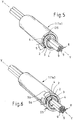
- Figures 5 and 6 show two embodiments of an adhesive tape according to the invention in the respective application, ie after the production of a cover for elongated material.
- an inventive adhesive tape in particular a cable winding tape for automobile construction, comprises a tape-shaped first carrier 2 which is provided on at least one side with a self-adhesive layer 3 which can in particular consist of a pressure-sensitive adhesive.
- an inventive adhesive tape in particular a cable winding tape for automobile construction, comprises a tape-shaped first carrier 2 which is provided on at least one side with a self-adhesive layer 3 which can in particular consist of a pressure-sensitive adhesive.
- a second carrier 4 is laminated onto the adhesive layer 3, which has a smaller width B4 than the width B2 of the first carrier 2.
- the individual embodiments of the tape according to the invention all have the same basic structure. However, they differ with regard to the details of the position of the second carrier 4 relative to the first carrier and in the design of the second carrier 4.
- the second carrier 4 runs on a side edge K4 flush with a side edge K2 of the first carrier 2, the first carrier 2 with the adhesive layer 3 protruding from the other side edge K4 of the second carrier 4 in the protruding area 5.
- the first carrier 2 with the adhesive layer 3 protrudes on both sides opposite the side edges K4 of the second carrier 4.
- the second carrier 4 can be arranged symmetrically or preferably asymmetrically to a longitudinal center axis or center plane XX of the first carrier 2.
- a smaller protruding area 5b can serve to pre-fix the goods to be wrapped, while the larger protruding area - as described in the first embodiment - can function as a closure.
- the first carrier 2 with the adhesive layer 3 protrudes on one side opposite a side edge K4 of the second carrier 4 and the second carrier 4 protrudes on the other side of the first carrier 2 (without adhesive coating 3) on one side opposite a side edge K2 of the first carrier 2 .
- the protruding area 7 without an adhesive coating 3 can be connected to the adhesive protruding area 5 when the goods are wrapped around.
- the second carrier 4 consists of at least two separate carrier parts 4a, 4b, the first carrier part 4a having a first width B4a and the second carrier part 4b having a second width B4b and the sum of the widths B4a, B4b of the carrier parts 4a, 4b is smaller than the width B2 of the first carrier 2.
- the areas 5a, 5b, 5c of the first carrier 2 located in the middle and the two edge-side areas covered by the adhesive layer 3 but not covered by the second carrier 4 can - similarly as with the execution according to Fig. 2 - Two (there could be more) zones for pre-fixing different goods to be wrapped, such as an electrical and a light guide strand, are used, while an edge area 5a, 5c in turn serves as a closure.
- An adhesive tape 1 according to the invention according to the embodiments shown can be glued on one side or overlapping on both sides.
- Two examples of coverings 1a produced with the adhesive tape 1 are shown in FIG Figures 5 and 6 shown.
- a preferred application of the adhesive tape 1 according to the invention is the wrapping of cable sets as an elongated product, which is shown in FIG Figures 5 and 6 is designated by the reference numeral 8 in each case.
- a cable harness in particular for the automotive industry, can be formed from several, each provided with insulation, in particular electrical lines 9 by at least partial wrapping - for example at non-insulated points of lines 9 - with the adhesive tape 1 according to the invention.
- the wrapping is not done in a helical manner, as is usual, but in such a way that a longitudinal axis of the tape (in Figs. 1 to 4 denoted by "XX”) is aligned essentially parallel to the direction YY of the elongated product 8.
- the adhesive tape 1 lies around the item in the form of an Archimedean spiral.
- Essentially parallel means that, for example, lateral kinks or twists running at a small acute angle, as can occur in cables 9 in a cable set 8 consisting of several conductors, are not taken into account.
- the running or longitudinal direction XX of the adhesive tape 1 is therefore essentially identical to the longitudinal direction YY of the item 8 to be wrapped.
- FIG. 3 shows an envelope 1a made from an inventive adhesive tape 1 according to the embodiment in FIG Fig. 1 is made.
- the only protruding area 5 that is present is located as a closure at the outer end of the helically wound adhesive tape 1.
- the inside of the envelope 1a is completely tack-free.
- FIG. 3 shows an envelope 1a made from an adhesive tape 1 according to the invention according to the embodiment in FIG Fig. 2 is made.
- One of the two protruding areas 5a that is present lies at the outer end of the helically wound adhesive tape 1, while the other protruding area 5b lies on the inside and has a fixing effect on the elongated product 8.
- both the first carrier 2 and the second carrier 4 consist of a film or a film composite material or a fabric, in particular a polyester or polyamide fabric, or a fleece. It is possible here by means of special carrier combinations to set a desired profile of properties for the adhesive tape 1 according to the invention.
- LV 312 "Protection systems for wiring harnesses in motor vehicles" contains test regulations as well as criteria and quantitative information for application-related important variables, such as temperature class, noise dampening behavior and abrasion resistance.
- LV 312 provides the classification given in Table 1 below.
- Table 1 Temperature classes according to LV 312 great Continuous use temperature Short term temperature Thermal overload temperature T U to T O in ° C (T O + 25) ° C (T O + 50) ° C A. - 40 to 85 110 ⁇ 2 135 ⁇ 3 B. - 40 to 100 125 ⁇ 3 150 ⁇ 3 C. - 40 to 125 150 ⁇ 3 175 ⁇ 3 D. - 40 to 150 175 ⁇ 3 200 ⁇ 3
- LV 312 provides the classification given in Table 2 below.
- Table 2 Abrasion protection classes according to LV 312 Abrasion class Requirement (number of strokes) A - no abrasion protection ⁇ 100 B - low abrasion protection 100-499 C - medium abrasion protection 500 - 999 D - high abrasion protection 1000-4999 E - very high abrasion protection 5000 and more
- LV 312 also provides for a division into five classes with regard to noise damping behavior, which is shown in Table 3 below.
- Table 3 Noise reduction classes according to LV 312 Noise reduction class Requirement A - no noise reduction 0 to 2 dB (A) B - low noise attenuation > 2 to 5 dB (A) C - medium noise reduction > 5 to 10 dB (A) D - high noise attenuation > 10 to 15 dB (A) E - very high noise attenuation > 15 dB (A)
- the guideline also describes, for example, test methods for the compatibility of adhesive tapes with electrical vehicle cables and for chemical resistance, fogging and flagging behavior.
- an adhesive tape 1 according to the invention not only enables easier production, but the adhesive tape 1 according to the invention also ensures improved strength of the closure. Furthermore, as mentioned, the largely tack-free inside provides the possibility of producing highly flexible sheaths 1a.
- UV-crosslinked acrylate adhesives hereinafter: UV acrylates
- 8 envelopes 1a are obtained for the elongated good, which can also be used in temperature class D according to Table 1 above under normal bending stress.
- the use of rubber-based adhesives is also possible, with the material-economical advantage of the invention with regard to the amount of adhesive already mentioned.
- the protective layer 1a corresponds at least to that of a conventional adhesive tape wound with a 50 percent overlap, but in the applied or assembled state with the structure: carrier 2 - adhesive layer 3 - carrier 4. In some areas, this thickness DS - as shown - can also be greater be.
- the grammage - and thus a thickness D3 - of the adhesive layer 3 depends in particular on the surface structure of the carrier 2, 4.
- an optimal specific mass of the adhesive layer 3 is preferably in the range from 70 to 140 g / m 2 , while a grammage of 40 to 80 g / m 2 appears to be sufficient for film carriers.
- the abrasion protection effect of an adhesive tape 1 according to the invention is increased again by the fact that the protective sheath 1a made from the adhesive tape 1 according to the invention is on the item 8, such as B. a cable set, can be movable. As a result, the forces acting are distributed over a larger area and can therefore only cause comparatively less damage. This effect becomes measurable when the casing 1a is movably attached to the abrasion mandrel of an abrasion measuring apparatus according to LV 312.
- Table 5 contains further information on the structure and the product properties of exemplary designs C1, C2, C3, only design C1 being an adhesive tape 1 according to the invention.
- Table 5 Basic data for adhesive tapes according to the invention size C1 C2 C3 first carrier 2 (outside) Aluminum composite foil PET fabric 120 g / m 2 PET fabric 120 g / m 2 Second carrier 4 (inside) PET fabric 120 g / m 2 PET fabric 120 g / m 2 PET fleece 240 g / m 2 Adhesive layer 3 UV acrylate 50 g / m 2 UV acrylate 140 g / m 2 Synthetic rubber 140 g / m 2 Thickness D (DIN EN 1942) 0.3 mm 0.5 mm 0.9 mm Breaking strength (DIN EN 14410) 300 N / cm 580 N / cm 300 N / cm Elongation at break (DIN EN 14410) 40% 45% 45% Noise reduction Class a class B Class D. Abrasion resistance Class E. Class E. Class E.
- the carrier composite of the first carrier 2 in the version C1 - referred to in the table field as "aluminum composite film” - consisted of a film which was in turn produced from a 9 ⁇ m thick aluminum film and a 15 ⁇ m thick PET film.
- the invention is not limited to the exemplary embodiment described - e.g. B. to the specified thicknesses of the layers of the aluminum composite material - limited., But also includes within the scope of claim 1 further combinations of Carriers 2, 4, which also take other adhesive tape properties into account, such as compatibility with electrical vehicle lines, chemical resistance, fogging and / or flagging behavior.
Landscapes
- Chemical & Material Sciences (AREA)
- Organic Chemistry (AREA)
- Adhesive Tapes (AREA)
Description
Die Erfindung betrifft ein Klebeband zur Längsummantelung von langgestrecktem Gut, insbesondere ein Kabelwickelband, umfassend einen bandförmigen Träger und mindestens eine auf einer Seite des Trägers aufgetragene Klebeschicht nach dem Oberbegriff des Anspruchs 1.The invention relates to an adhesive tape for the longitudinal sheathing of elongated goods, in particular a cable winding tape, comprising a tape-shaped carrier and at least one adhesive layer applied to one side of the carrier according to the preamble of
Im Automobilbereich werden Kabelsätze oftmals mit Klebebändern umwickelt, wobei vor allem textile Klebebänder neben der reinen Bündelungsfunktion mittlerweile zahlreiche Zusatzfunktionen, wie den Schutz der Leitungen vor Abrieb oder die Dämpfung von Klapper- oder Vibrationsgeräuschen, übernommen haben. Weit verbreitet ist dabei der Einsatz sowohl von Gewebeklebebändern, als auch von verschiedenartigen Vliesklebebändern, Folienklebebändern und SchaumstoffklebebändernIn the automotive sector, cable harnesses are often wrapped with adhesive tapes, with textile adhesive tapes in particular taking on numerous additional functions in addition to their pure bundling function, such as protecting cables from abrasion or dampening rattling or vibration noises. The use of fabric adhesive tapes as well as various types of non-woven adhesive tapes, film adhesive tapes and foam adhesive tapes is widespread
Als Alternative zu einer weithin üblichen Bewicklung von langgestrecktem Gut, bei der beispielsweise Kabelsätze mit einem Klebeband umwickelt werden, das in Längsrichtung des Gutes mit teilweiser Überlappung schraubenlinienförmig um das Gut geführt wird, werden auch verschiedene andere Systeme zur Längsumhüllung angeboten. Marktüblich vertreten sind dabei derzeit vollflächig klebende Längsverklebungsbänder zur automatischen oder manuellen Verarbeitung und Produkte mit einem nicht klebenden Mittelteil und einem oder zwei seitlichen Klebestreifen, wie sie beispielsweise in der
Auf ein Klebeband der eingangs genannten Art, das zur Längsummantelung von langgestrecktem Gut eingesetzt wird, bezieht sich u.a. die
Die
Das deutsche Gebrauchsmuster
Das deutsche Gebrauchsmuster
Die
Eine weitere dem eingangs genannten Klebeband nahekommende technische Lösung ist die im deutschen Gebrauchsmuster
Als technologischer Hintergrund zur Erfindung ist auch die
Der Erfindung liegt die Aufgabe zugrunde, ein Klebeband der eingangs genannten Art zu schaffen, das eine weitgehend klebfreie Innenfläche aufweist, das bei der Längsummantelung sowohl manuell, als auch maschinell leicht verarbeitbar ist und dabei einen verringerten Herstellungs- und Montageaufwand aufweist. Dabei soll ein an spezielle Anwendungsfälle angepasstes Klebeband entwickelt werden, welches in sich die Möglichkeit einer hochflexiblen Umhüllung mit einem hohen Hitzeschutz und mit einem hohen Abriebschutz bei einer weitgehend klebfreien Innenfläche mit leichter Verarbeitung bei manueller oder maschineller Längsummantelung und dabei einem geringen Herstellungs- und Montageaufwand vereint.The invention is based on the object of creating an adhesive tape of the type mentioned at the outset, which has a largely tack-free inner surface, which can be easily processed both manually and mechanically in the longitudinal sheathing and has reduced manufacturing and assembly costs. An adhesive tape adapted to special applications is to be developed, which combines the possibility of a highly flexible covering with high heat protection and high abrasion protection with a largely tack-free inner surface with easy processing with manual or mechanical longitudinal wrapping and at the same time low manufacturing and assembly costs .
Erfindungsgemäß wird dies gemäß Anspruch 1 dadurch erreicht, dass der erste Träger (2) aus einem Aluminiumverbundmaterial und der zweite Träger (4) aus einem PET-Gewebe bestehen, wobei das Aluminiumverbundmaterial aus mindestens zwei Schichten besteht, von denen die erste Schicht eine Aluminiumschicht ist und die zweite Schicht, auf die die Klebeschicht (3) aufgebracht ist, aus einer temperaturbeständigen Kunststofffolie oder aus textilem Trägermaterial besteht.According to the invention, this is achieved according to
Durch die Erfindung wird auf diese Weise ein Klebeband bereitgestellt, das einerseits eine weitgehend klebfreie Innenseite aufweist, und damit vorteilhafterweise die Möglichkeit der Herstellung hochflexibler Umhüllungen auch für große Kabelsatzdurchmesser bietet, dessen Herstellung aber anderseits insofern vereinfacht ist, als sie nicht den Einsatz eines weiteren schmalen oder auch breiteren Klebebandstreifens erfordert.In this way, the invention provides an adhesive tape which on the one hand has a largely tack-free inside and thus advantageously offers the possibility of producing highly flexible sheaths even for large cable harness diameters, but on the other hand its production is simplified insofar as it does not require the use of a further narrow one or a wider strip of tape.
Die klebenden Zonen befinden sich vorteilhafterweise bei dem erfindungsgemäßen Band nur auf einer Seite der Bahn und können bei einer Rollenfertigung problemlos - ohne die Verwendung eines Releaseliners - nach innen gewickelt werden. Ebenso kann das Band bei seinem Einsatz leicht wieder von einer solchen Rolle abgewickelt werden.In the case of the tape according to the invention, the adhesive zones are advantageously only on one side of the web and, in the case of roll production, can be wound inwards without any problems - without the use of a release liner. Likewise, the tape can easily be unwound again from such a roll when it is used.
Dadurch, dass jeweils nur eine der miteinander verbundenen Trägerbahnen mit einer Klebeschicht versehen ist, halbiert sich im Vergleich zu der vorstehend beschriebenen bekannten technischen Lösung der Klebstoffverbrauch.Because only one of the interconnected carrier webs is provided with an adhesive layer, the adhesive consumption is halved compared to the known technical solution described above.
Hierbei können vorteilhafterweise verschiedene Ausführungsformen vorgesehen sein. So kann der zweite Träger an einer Seitenkante bündig mit einer Seitenkante des ersten Trägers verlaufen, wobei der erste Träger mit der Klebeschicht gegenüber der anderen Seitenkante des zweiten Trägers übersteht. Der erste Träger kann mit der Klebeschicht auch beidseitig gegenüber den Seitenkanten des zweiten Trägers überstehen oder es kann vorgesehen sein, dass der erste Träger mit der Klebeschicht einseitig gegenüber einer Seitenkante des zweiten Trägers übersteht und der zweite Träger auf der anderen Seite des ersten Trägers einseitig gegenüber einer Seitenkante des ersten Trägers übersteht. Des Weiteren ist es auch möglich, das der zweite Träger mindestens aus zwei voneinander getrennten Trägerteilen besteht, wobei das erste Trägerteil eine erste Breite und das zweite Trägerteil eine zweite Breite aufweist, wobei die Summe der Breiten der Trägerteile kleiner ist als die Breite des ersten Trägers.Various embodiments can advantageously be provided here. The second carrier can thus run on one side edge flush with a side edge of the first carrier, the first carrier with the adhesive layer protruding from the other side edge of the second carrier. The first carrier with the adhesive layer can also protrude on both sides opposite the side edges of the second carrier or it can be provided that the first carrier with the adhesive layer protrudes on one side opposite a side edge of the second carrier and the second carrier on the other side of the first carrier on one side opposite one side edge of the first carrier protrudes. Furthermore, it is also possible for the second carrier to consist of at least two separate carrier parts, the first carrier part having a first width and the second carrier part having a second width, the sum of the widths of the carrier parts being smaller than the width of the first carrier .
Die seitlich überstehenden klebenden Bereiche des ersten Trägers können zur besseren Handhabung mit einem Trennpapier oder einer Trennfolie, die kurz vor der Applikation entfernt wird, abgedeckt sein.The laterally protruding adhesive areas of the first carrier can be covered with a release paper or a release film, which is removed shortly before application, for better handling.
Die beiden Träger bestehen aus unterschiedlichen Materialien, wobei zur Erzielung bestimmter erwünschter Eigenschaften - vorteilhafterweise auch unter Berücksichtigung materialökonomischer Aspekte - eine bestimmte Trägerkombinationen gewählt ist.The two carriers are made of different materials, with a specific carrier combination being selected in order to achieve certain desired properties - advantageously also taking into account material-economical aspects.
So kann mit dem ersten Träger aus einem Aluminiumverbundmaterial, der in einer Umhüllung für langgestrecktes Gut eine Außenlage bildet, und mit dem zweiten Träger aus PET-Gewebe (PET - Polyethylenterephtalat), der in der Umhüllung eine Innenlage bildet, ein hoher Hitzeschutz in Kombination mit einem hohen Abriebschutz erzielt werden.Thus, with the first carrier made of an aluminum composite material, which forms an outer layer in a cover for elongated goods, and with the second carrier made of PET fabric (PET - polyethylene terephthalate), which forms an inner layer in the cover, a high level of heat protection in combination with a high level of abrasion protection can be achieved.
Weitere vorteilhafte Ausgestaltungsmerkmale der Erfindung sind in den Unteransprüchen sowie der folgenden Beschreibung enthalten.Further advantageous design features of the invention are contained in the dependent claims and the following description.
Anhand mehrerer durch die beiliegenden Zeichnungen veranschaulichter erfindungsgemäßer Ausführungsbeispiele wird die Erfindung näher erläutert.The invention is explained in more detail with the aid of several exemplary embodiments according to the invention illustrated by the accompanying drawings.
Dabei zeigen
In den Figuren der Zeichnung sind gleiche Teile stets auch mit den gleichen Bezugszeichen versehen, so dass sie in der Regel auch jeweils nur einmal beschrieben werden.In the figures of the drawing, the same parts are always provided with the same reference numerals, so that they are usually only described once.
Wie zunächst
Wie zunächst
Erfindungsgemäß ist vorgesehen, dass auf die Klebeschicht 3 ein zweiter Träger 4 auflaminiert ist, der eine geringere Breite B4 aufweist als die Breite B2 des ersten Trägers 2.According to the invention it is provided that a
Die einzelnen Ausführungsbeispiele des erfindungsgemäßen Bandes weisen alle diesen gleichen Grundaufbau auf. Sie unterscheiden sich jedoch hinsichtlich der Details der Lage des zweiten Trägers 4 relativ zum ersten Träger und in der Ausführung des zweiten Trägers 4.The individual embodiments of the tape according to the invention all have the same basic structure. However, they differ with regard to the details of the position of the
In der ersten Ausführung gemäß
In der zweiten Ausführung gemäß
In der dritten Ausführung gemäß
In der vierten Ausführung gemäß
Vor der Applikation des erfindungsgemäßen Klebebandes können - wie in
Ein erfindungsgemäßes Klebeband 1 gemäß den dargestellten Ausführungen kann einseitig oder beidseitig überlappend verklebt werden. Zwei Beispiele für mit dem Klebeband 1 hergestellte Umhüllungen 1a sind in
Einen bevorzugten Anwendungsfall des erfindungsgemäßen Klebebandes 1 stellt das Umwickeln von Kabelsätzen als langgestrecktem Gut dar, das in
Bei allen figürlich dargestellten Ausführungsformen kann vorgesehen sein, dass sowohl der erste Träger 2, als auch der zweite Träger 4 aus einer Folie oder einem Folienverbundmaterial oder aus einem Gewebe, insbesondere aus einem Polyester- oder Polyamidgewebe, oder aus einem Vlies bestehen. Hierbei ist es durch spezielle Trägerkombinationen möglich, ein gewünschtes Eigenschaftsprofil des erfindungsgemäßen Klebebandes 1 einzustellen.In all the embodiments shown in the figures, it can be provided that both the
Die Prüfung des Eigenschaftsprofils von Kabelschutzsystemen erfolgt in der Automobilindustrie zumeist nach umfangreichen Normenwerken. Als gemeinsame Prüfrichtlinie der Firmen Audi, BMW, Daimler, Porsche und VW enthält die LV 312 "Schutzsysteme für Leitungssätze in Kraftfahrzeugen" Prüfungsvorschriften sowie Kriterien und quantitative Angaben für anwendungstechnisch wichtige Größen, wie die Temperaturklasse, das Geräuschdämpfungsverhalten und für die Abriebbeständigkeit.The testing of the property profile of cable protection systems in the automotive industry is mostly carried out according to extensive standards. As a common test guideline of the companies Audi, BMW, Daimler, Porsche and VW, LV 312 "Protection systems for wiring harnesses in motor vehicles" contains test regulations as well as criteria and quantitative information for application-related important variables, such as temperature class, noise dampening behavior and abrasion resistance.
Hinsichtlich der thermischen Beständigkeit ist in der LV 312 die in der nachstehenden Tabelle 1 wiedergegebene Klassifizierung vorgesehen.
Hinsichtlich der Abriebbeständigkeit ist in der LV 312 die in der nachstehenden Tabelle 2 wiedergegebene Klassifizierung vorgesehen.
Auch hinsichtlich des Geräuschdämpfungsverhaltens sieht die LV 312 eine Einteilung in fünf Klassen vor, die in der nachstehenden Tabelle 3 wiedergegeben ist.
Als weitere anwendungstechnisch wichtige Prüfungen sind in der genannten Richtlinie beispielsweise auch Prüfmethoden für die Kompatibilität von Klebebändern mit elektrischen Fahrzeugleitungen sowie für die Chemikalienbeständigkeit, das Foggingsowie für das Flagging-Verhalten beschrieben.As further tests that are important in terms of application, the guideline also describes, for example, test methods for the compatibility of adhesive tapes with electrical vehicle cables and for chemical resistance, fogging and flagging behavior.
Schutzsysteme gegen Strahlungshitzeschutz werden entsprechend US-Norm SAE J2302 "Thermal effectiveness of sleeve insulations" charakterisiert.Protective systems against radiation heat protection are characterized in accordance with US standard SAE J2302 "Thermal effectiveness of sleeve insulations".
Unter Verzicht auf den Einsatz der bei bekannten Sleeveumhüllungen vorgesehenen schmalen Verschlussstreifen oder zusätzlichen Klebebänder wird mit einem erfindungsgemäßen Klebeband 1 nicht nur eine einfachere Herstellung möglich, sondern das erfindungsgemäße Klebeband 1 gewährleistet auch eine verbesserte Festigkeit des Verschlusses. Des Weiteren ist durch die weitgehend klebfreie Innenseite - wie erwähnt - die Möglichkeit der Herstellung hochflexibler Umhüllungen 1a gegeben. Bei Einsatz von UV-vernetzten Acrylatklebstoffen (im Weiteren: UV-Acrylate), die eine hohe Temperaturbeständigkeit aufweisen, werden so für das langgestreckte Gut 8 Umhüllungen 1a erhalten, die bei normaler Biegebeanspruchung auch bei der Temperaturklasse D gemäß der vorstehenden Tabelle 1 einsetzbar sind. Grundsätzlich ist aber auch der Einsatz von kautschukbasierten Klebstoffen möglich, wobei der materialökonomische Vorteil der Erfindung in Bezug auf die Klebstoffmenge bereits erwähnt wurde.By dispensing with the use of the narrow closure strips or additional adhesive tapes provided in known sleeve wrappings, an
Durch den doppellagigen Aufbau des erfindungsgemäßen Klebebandes 1 mit dem ersten Träger 2 und dem zweiten Träger 4 wird ein erheblich höherer Abriebschutz erreicht als bei einlagigen Ummantelungen. Die Dicke (Bezugszeichen DS in
Die Grammatur - und damit eine Dicke D3 - der Klebeschicht 3 richtet sich insbesondere nach der Oberflächenstruktur der Träger 2, 4. Für textile Träger 2, 4 liegt eine optimale spezifische Masse der Klebeschicht 3 vorzugsweise im Bereich von 70 bis 140 g/m2, während bei Folienträgern bereits eine Grammatur von 40 bis 80 g/m2 als ausreichend erscheint.The grammage - and thus a thickness D3 - of the
Bei Wahl unterschiedlicher Materialien für die beiden Träger 2, 4, die im applizierten Zustand des erfindungsgemäßen Bandes 1 jeweils die innere und äußere Seite der Umhüllung 1a bilden, können - wie erwähnt - leicht verschiedenartige Funktionen von Klebebändern miteinander kombiniert werden.If different materials are selected for the two
Die Ausführung gemäß der Erfindung ist dabei:
- Erster Träger 2: Verbundmaterial aus mindestens zwei Schichten, wobei die erste der Schichten eine metallische Schicht - und zwar eine Aluminiumschicht - ist, und auf die zweite Schicht, die aus einer temperaturbeständigen Kunststofffolie oder textilem Trägermaterial besteht, die - vorzugsweise druckempfindliche -
Klebeschicht 3 aufgebracht ist; zweiter Träger 4: PET-Gewebe; Funktionen: Hitze- und Abriebschutz;
- First carrier 2: composite material consisting of at least two layers, the first of the layers being a metallic layer - namely an aluminum layer - and the - preferably pressure-sensitive -
adhesive layer 3 applied to the second layer, which consists of a temperature-resistant plastic film or textile carrier material is; second carrier 4: PET fabric; Functions: heat and abrasion protection;
Nicht erfindungsgemäße Ausführungen sind:
- erster Träger 2: PET-Gewebe; zweiter Träger 4: PET-Gewebe; Funktion: erhöhter Abriebschutz;
- - erster Träger 2: PET-Gewebe; zweiter Träger 4: PET-Vlies; Funktionen: Abriebschutz und Geräuschdämpfung;
- - erster Träger 2: PET-Folie; zweiter Träger 4: PET-Gewebe; Funktionen: Feuchtigkeits- und Abriebschutz;
- - erster Träger 2: PA-Gewebe; zweiter Träger 4: PET-Gewebe; Funktion: erhöhter Abriebschutz.
- first carrier 2: PET fabric; second carrier 4: PET fabric; Function: increased abrasion protection;
- - first carrier 2: PET fabric; second carrier 4: PET fleece; Functions: abrasion protection and noise reduction;
- - first carrier 2: PET film; second carrier 4: PET fabric; Functions: moisture and abrasion protection;
- - first carrier 2: PA fabric; second carrier 4: PET fabric; Function: increased abrasion protection.
Gegenüber konventionellen Kabelwickelbändern und auch gegenüber Umhüllungen, die aus drei einseitig klebenden Bändern bzw. Klebebandstreifen hergestellt sind und eine teilweise klebende Innenseite aufweisen, wird die Abriebschutzwirkung eines erfindungsgemäßen Klebebandes 1 nochmals dadurch gesteigert, dass die aus dem erfindungsgemäßen Klebeband 1 hergestellte Schutzumhüllung 1a auf dem Gut 8, wie z. B. einem Kabelsatz, beweglich sein kann. Dies hat zur Folge, dass einwirkende Kräfte sich auf eine größere Fläche verteilen und dadurch nur vergleichsweise geringere Schädigungen hervorrufen können. Messbar wird dieser Effekt bei einer beweglichen Befestigung der Umhüllung 1a auf dem Abriebdorn einer Abriebmessapparatur nach LV 312.Compared to conventional cable wrapping tapes and also compared to sheaths that are made from three single-sided adhesive tapes or strips of adhesive tape and have a partially adhesive inside, the abrasion protection effect of an
Dies verdeutlicht auch die nachstehende Tabelle 4, in der die bei einer Prüfung gemäß LV 312 an einem 5-mm-Dorn erreichte Anzahl der Doppelhübe einer mit einem Klebeband 1 hergestellten Umhüllung 1a (in der Tabelle mit "C2" bezeichnet) den entsprechenden Werten von Umhüllungen bekannter Bänder gegenüber gestellt ist. Das geprüfte Klebeband 1 wies dabei zwei PET-Gewebe-Träger 2, 4 auf und wurde in der Abriebapparatur einseitig befestigt. Bei der in der Tabelle mit "A" bezeichneten Umhüllung handelte es sich um eine solche gemäß der eingangs erwähnten
Tabelle 5 enthält weitere Angaben zum Aufbau und den Produkteigenschaften exemplarischer Ausführungen C1, C2, C3, wobei es sich nur bei der Ausführung C1 um ein erfindungsgemäßes Klebeband 1 handelt.
Der Trägerverbund des ersten Trägers 2 in der Ausführung C1 - im Tabellenfeld mit "Alu-Verbundfolie" bezeichnet - bestand dabei aus einer Folie, die ihrerseits aus einer 9 µm starken Aluminiumfolie und einer 15 µm starken PET-Folie hergestellt worden war.The carrier composite of the
Die Erfindung ist nicht auf das beschriebene Ausführungsbeispiel - z. B. auf die angegebenen Dicken der Schichten des Aluminiumverbundmaterials - beschränkt., sondern umfasst auch im Rahmen des Anspruchs 1 weitere Kombinationen von Trägern 2, 4, die zusätzlich auch anderen Klebebandeigenschaften, wie Kompatibilität mit elektrischen Fahrzeugleitungen, Chemikalienbeständigkeit, Fogging-und/oder Flagging-Verhaiten Rechnung tragen.The invention is not limited to the exemplary embodiment described - e.g. B. to the specified thicknesses of the layers of the aluminum composite material - limited., But also includes within the scope of
- 11
- Klebebandduct tape
- 22
- erster Trägerfirst carrier
- 33
- KlebeschichtAdhesive layer
- 44th
- zweiter Trägersecond carrier
- 4a4a
- erstes Trägerteil von 4first support part of 4
- 4b4b
- zweites Trägerteil von 4second support part of 4
- 5, 5a, 5b, 5c5, 5a, 5b, 5c
- Überstandsbereiche von 2/3 gegenüber 4Overhang areas of 2/3 compared to 4
- 66th
- Trennfolie auf 5, 5a, 5b, 5cRelease film on 5, 5a, 5b, 5c
- 77th
- Überstandsbereich von 4 gegenüber 2Overhang area of 4 versus 2
- 88th
- langggestrecktes Gut (Kabelsatz)elongated good (cable set)
- 99
- Kabel von 8Cable from 8
- B2B2
- Breite von 2Width of 2
- B4B4
- Breite von 4Width of 4
- B4aB4a
- Breite von 4aWidth of 4a
- B4bB4b
- Breite von 4bWidth of 4b
- DD.
- Dicke von 1Thickness of 1
- D3D3
- Dicke von 3Thickness of 3
- DSDS
- Dicke von 1aThickness of 1a
- K2K2
- Kante von 2Edge of 2
- K4K4
- Kante von 4Edge of 4
- K4aK4a
- Kante von 4aEdge of 4a
- K4bK4b
- Kante von 4bEdge of 4b
- X-XX-X
- Mittenachse bzw. -ebene von 2Center axis or plane of 2
- Y-YY-Y
- Längserstreckungsrichtung/-achse von 8Longitudinal direction / axis of 8
Claims (12)
- Adhesive tape (1) for longitudinally sheathing elongate goods (8), comprising a first tape-like carrier (2) and at least one adhesive layer (3) which is applied on one side of the first carrier (2) and which extends over the entire width (B2) of the first carrier (2), wherein a second carrier (4) is laminated onto the adhesive layer (3), said second carrier having a smaller width (B4) than the width (B2) of the first carrier (2), as a result of which the first carrier (2) protrudes along with the adhesive layer (3) at least in relation to a side edge of the second carrier (4), wherein the second carrier (4) is not provided with an adhesive layer and is intended to be the carrier next to the elongate goods (8) in the sheathed state of the elongate goods (8),
characterized in that the first carrier (2) is composed of an aluminium composite material and the second carrier (4) is composed of a PET woven fabric, wherein the aluminium composite material is composed of at least two layers, of which the first layer is an aluminium layer and the second layer, onto which the adhesive layer (3) is applied, is composed of a temperature-resistant plastic film or of textile carrier material. - Adhesive tape (1) according to Claim 1,
characterized in that, at one side edge (K4), the second carrier (4) runs flush with a side edge (K2) of the first carrier (2), wherein the first carrier (2) protrudes along with the adhesive layer (3) in relation to the other side edge (K4) of the second carrier (4). - Adhesive tape (1) according to Claim 1,
characterized in that the first carrier (2) protrudes along with the adhesive layer (3) on both sides in relation to the side edges (K4) of the second carrier (4). - Adhesive tape (1) according to Claim 3,
characterized in that the second carrier (4) is arranged asymmetrically with respect to a longitudinally running centre axis (X-X) of the first carrier (2). - Adhesive tape (1) according to Claim 1,
characterized in that the first carrier (2) protrudes along with the adhesive layer (3) on one side in relation to a side edge (K4) of the second carrier (4), and, on the other side of the first carrier (2), the second carrier (4) protrudes on one side in relation to a side edge (K2) of the first carrier (2). - Adhesive tape (1) according to one of Claims 1 to 5,
characterized in that the second carrier (4) is composed at least of two separate carrier parts (4a, 4b), wherein the first carrier part (4a) has a first width (B4a) and the second carrier part (4b) has a second width (B4b), and the sum of the widths (B4a, B4b) of the carrier parts (4a, 4b) is smaller than the width (B2) of the first carrier (2). - Adhesive tape (1) according to one of Claims 1 to 6,
characterized in that regions (5, 5a, 5b, 5c) of the first carrier (2) which protrude laterally in relation to the second carrier (4) and which are coated with the adhesive layer (3) are covered with a release paper or a release film/foil (7). - Adhesive tape (1) according to one of Claims 1 to 7,
characterized in that the adhesive layer (3) is composed of a UV-crosslinked acrylate adhesive material or of a rubber-based adhesive material. - Adhesive tape (1) according to one of Claims 1 to 8,
characterized in that the adhesive layer (3) has a grammage in the range of 70 to 140 g/m2. - Cable harness composed of a cable set (8) which has a sheath (1a) with an adhesive tape (1) according to one of Claims 1 to 9, wherein a longitudinal axis (X-X) of the adhesive tape (1) is oriented substantially parallel to the direction of extent (Y-Y) of the cable set (8).
- Cable harness according to Claim 10,
characterized in that the adhesive tape (1) - as seen in cross section - is wrapped in the form of an Archimedean spiral around the cable set (8). - Cable harness according to Claim 10 or 11,
characterized in that the sheath (1a) is movable on the cable set (8).
Applications Claiming Priority (1)
| Application Number | Priority Date | Filing Date | Title |
|---|---|---|---|
| DE202007012475U DE202007012475U1 (en) | 2007-09-06 | 2007-09-06 | Adhesive tape for longitudinal wrapping of elongated material |
Publications (2)
| Publication Number | Publication Date |
|---|---|
| EP2034576A1 EP2034576A1 (en) | 2009-03-11 |
| EP2034576B1 true EP2034576B1 (en) | 2020-10-07 |
Family
ID=39994202
Family Applications (1)
| Application Number | Title | Priority Date | Filing Date |
|---|---|---|---|
| EP08162060.1A Active EP2034576B1 (en) | 2007-09-06 | 2008-08-08 | Adhesive band for longitudinal sheathing of extended goods |
Country Status (2)
| Country | Link |
|---|---|
| EP (1) | EP2034576B1 (en) |
| DE (1) | DE202007012475U1 (en) |
Families Citing this family (22)
| Publication number | Priority date | Publication date | Assignee | Title |
|---|---|---|---|---|
| DE102008056554A1 (en) * | 2008-11-10 | 2010-05-20 | Tesa Se | Sheath for wrapping elongated goods e.g. cables, has adhesive tape overlapping and protruding from edge of covering, where tape and/or covering includes color marks that are optically and/or haptically differentiated from each other |
| DE102011005200A1 (en) * | 2011-03-07 | 2012-09-13 | Tesa Se | Adhesive tape for wrapping elongated goods, in particular cable harnesses and jacketing methods |
| DE102011005162A1 (en) * | 2011-03-07 | 2012-09-13 | Tesa Se | Adhesive tape for cable bandaging |
| DE102011005763A1 (en) * | 2011-03-18 | 2012-09-20 | Tesa Se | Adhesive tape for wrapping elongated goods, in particular cable harnesses and jacketing methods |
| ES2489217T3 (en) | 2011-10-06 | 2014-09-01 | Coroplast Fritz Müller Gmbh & Co. Kg | Procedure for producing an adhesive tape that can be used particularly for the longitudinal coating of elongated products, as well as a device for performing the procedure |
| DE202011110445U1 (en) | 2011-10-06 | 2014-01-22 | Coroplast Fritz Müller Gmbh & Co. Kg | Device for producing an adhesive tape which can be used in particular for the longitudinal covering of elongate material |
| EP3005502B1 (en) * | 2013-05-28 | 2018-03-07 | Federal-Mogul Powertrain, Inc. | Wrapped textile sleeve with bonded closure mechanism and method of construction thereof |
| DE102013111219B4 (en) | 2013-10-10 | 2024-04-18 | Coroplast Fritz Müller Gmbh & Co. Kg | "Wrapping material for an elongated item and its use" |
| DE102014113769A1 (en) | 2014-09-23 | 2016-03-24 | Certoplast Vorwerk & Sohn Gmbh | Method for producing a casing for elongated material |
| EP3224920B1 (en) * | 2014-11-26 | 2020-07-22 | Federal-Mogul Powertrain LLC | Nonwoven acoustic sleeve and method of construction thereof |
| DE202017100009U1 (en) | 2017-01-03 | 2017-01-20 | Certoplast Technische Klebebänder Gmbh | Adhesive tape, in particular winding tape |
| CN107123546B (en) * | 2017-06-23 | 2018-10-26 | 中达电子(江苏)有限公司 | The preparation method of coiling, winding and coiling |
| CN110137682A (en) * | 2018-02-02 | 2019-08-16 | 康普技术有限责任公司 | For adjusting the component and electrical tilt antenna system of electrical tilt antenna |
| EP3957695A1 (en) * | 2020-08-17 | 2022-02-23 | tesa SE | Adhesive tape for sheathing elongated goods, in particular cable sets and sheathing method |
| DE102021201856A1 (en) | 2021-02-26 | 2022-09-01 | Tesa Se | Adhesive tape for wrapping elongate goods, in particular cable harnesses and methods for wrapping |
| DE102021115573A1 (en) * | 2021-06-16 | 2022-12-22 | Tdk Electronics Ag | Arrangement for protecting a sensor device |
| WO2023051890A1 (en) | 2021-09-28 | 2023-04-06 | Coroplast Fritz Müller Gmbh & Co. Kg | Longitudinally coated, electromagnetically shielded elongated product, sleeve for coating the product, and use thereof |
| DE102021210866A1 (en) | 2021-09-28 | 2023-03-30 | Tesa Se | Adhesive tape for wrapping elongate goods, in particular cable harnesses and methods for wrapping |
| DE102021125009A1 (en) | 2021-09-28 | 2023-03-30 | Coroplast Fritz Müller GmbH & Co. K. G. | Longitudinally sheathed, electromagnetically shielded, elongate goods and sheathing for sheathing the goods and use of the same |
| DE202022101548U1 (en) | 2022-03-24 | 2022-04-06 | Certoplast Technische Klebebänder Gmbh | Adhesive tape, in particular wrapping tape for sheathing cables in automobiles |
| DE202022105886U1 (en) | 2022-10-19 | 2022-11-14 | Certoplast Technische Klebebänder Gmbh | duct tape |
| DE102022127834A1 (en) | 2022-10-21 | 2024-05-02 | Tesa Se | Adhesive tape for wrapping elongated goods |
Citations (11)
| Publication number | Priority date | Publication date | Assignee | Title |
|---|---|---|---|---|
| US4327246A (en) * | 1980-02-19 | 1982-04-27 | Belden Corporation | Electric cables with improved shielding members |
| DE9400574U1 (en) | 1993-10-06 | 1994-04-14 | Coroplast Fritz Mueller Kg | Adhesive tape, especially for wrapping a cable set |
| DE29510907U1 (en) | 1995-07-06 | 1995-10-19 | Mohr Karl Eugen | Protective sheath for cables, strands and the like. |
| DE29711387U1 (en) * | 1997-06-30 | 1997-11-06 | Bentley Harris Inc | Sheathing for elongated objects |
| DE10036805A1 (en) * | 2000-07-28 | 2002-02-07 | Tesa Ag | Process for sheathing elongated goods, such as cable sets in particular |
| DE10042732A1 (en) | 2000-08-31 | 2002-03-28 | Tesa Ag | Process for sheathing elongated goods, such as in particular cable sets with an adhesive tape |
| EP1615238A1 (en) | 2004-07-10 | 2006-01-11 | Coroplast Fritz Müller GmbH & Co. KG | thermically insulting technical adhesive tape and cable bundle having high temperature resistance |
| DE102005013124A1 (en) | 2005-03-18 | 2006-09-21 | Certoplast Vorwerk & Sohn Gmbh | Protective jacket useful for cable carriers with film or nonwoven material support where support is coated with melt or dispersion adhesive |
| WO2006108871A1 (en) | 2005-04-14 | 2006-10-19 | Tesa Ag | Method for covering an elongated product in particular cable looms with a coating |
| US20070104927A1 (en) | 2005-11-07 | 2007-05-10 | Yazaki Corporation | Covering sheet and wire harness |
| US20070154684A1 (en) * | 2005-12-30 | 2007-07-05 | Baer Angela L | Self-adhesive protective substrate |
-
2007
- 2007-09-06 DE DE202007012475U patent/DE202007012475U1/en not_active Expired - Lifetime
-
2008
- 2008-08-08 EP EP08162060.1A patent/EP2034576B1/en active Active
Patent Citations (12)
| Publication number | Priority date | Publication date | Assignee | Title |
|---|---|---|---|---|
| US4327246A (en) * | 1980-02-19 | 1982-04-27 | Belden Corporation | Electric cables with improved shielding members |
| DE9400574U1 (en) | 1993-10-06 | 1994-04-14 | Coroplast Fritz Mueller Kg | Adhesive tape, especially for wrapping a cable set |
| DE29510907U1 (en) | 1995-07-06 | 1995-10-19 | Mohr Karl Eugen | Protective sheath for cables, strands and the like. |
| DE29711387U1 (en) * | 1997-06-30 | 1997-11-06 | Bentley Harris Inc | Sheathing for elongated objects |
| DE10036805A1 (en) * | 2000-07-28 | 2002-02-07 | Tesa Ag | Process for sheathing elongated goods, such as cable sets in particular |
| DE10042732A1 (en) | 2000-08-31 | 2002-03-28 | Tesa Ag | Process for sheathing elongated goods, such as in particular cable sets with an adhesive tape |
| EP1615238A1 (en) | 2004-07-10 | 2006-01-11 | Coroplast Fritz Müller GmbH & Co. KG | thermically insulting technical adhesive tape and cable bundle having high temperature resistance |
| DE102005013124A1 (en) | 2005-03-18 | 2006-09-21 | Certoplast Vorwerk & Sohn Gmbh | Protective jacket useful for cable carriers with film or nonwoven material support where support is coated with melt or dispersion adhesive |
| WO2006108871A1 (en) | 2005-04-14 | 2006-10-19 | Tesa Ag | Method for covering an elongated product in particular cable looms with a coating |
| DE102005017381A1 (en) | 2005-04-14 | 2006-10-19 | Tesa Ag | A method for wrapping elongated material, in particular cable harnesses, with a sheath |
| US20070104927A1 (en) | 2005-11-07 | 2007-05-10 | Yazaki Corporation | Covering sheet and wire harness |
| US20070154684A1 (en) * | 2005-12-30 | 2007-07-05 | Baer Angela L | Self-adhesive protective substrate |
Also Published As
| Publication number | Publication date |
|---|---|
| DE202007012475U1 (en) | 2009-01-08 |
| EP2034576A1 (en) | 2009-03-11 |
Similar Documents
| Publication | Publication Date | Title |
|---|---|---|
| EP2034576B1 (en) | Adhesive band for longitudinal sheathing of extended goods | |
| EP2627539B1 (en) | Adhesive tape and tube casing produced from the adhesive tape | |
| EP1848006B1 (en) | Adhesive tape for sheathing elongated goods, application of this adhesive tape and harness with this adhesive tape | |
| EP1615238B2 (en) | Thermically insulting technical adhesive tape and cable bundle having high temperature resistance | |
| EP3197968B1 (en) | Method for producing a cladding for elongated material | |
| EP1988140B1 (en) | Heat reflective adhesive tape with high abrasion protection | |
| DE19732958A1 (en) | Adhesive tape for wrapping elongated goods, such as cable sets, plastic profiles or the like. | |
| DE2329532C3 (en) | Multi-layer flexible electrical tape or sheet | |
| EP0647691B1 (en) | Adhesive tape and its use in wrapping a wire harness | |
| DE102013111219B4 (en) | "Wrapping material for an elongated item and its use" | |
| EP1983036A1 (en) | Heat reflecting adhesive tape | |
| EP2497807A1 (en) | Adhesive tape for bundling cables | |
| EP3765577B1 (en) | Adhesive tape, in particular wrapping tape | |
| EP0525519B1 (en) | Heat-shrinkable composite sheet | |
| DE102008025580A1 (en) | Winding core for producing wound adhesive tape, has compression layer formed in carrier and provided with wave-shaped cross-section, where outer region of carrier is joined to upper side of compression layer | |
| DE102014114794A1 (en) | Method for producing a casing for elongated material | |
| EP3713758A1 (en) | Method for producing sheathing for an elongate item | |
| WO2023051890A1 (en) | Longitudinally coated, electromagnetically shielded elongated product, sleeve for coating the product, and use thereof | |
| DE102021125009A1 (en) | Longitudinally sheathed, electromagnetically shielded, elongate goods and sheathing for sheathing the goods and use of the same | |
| DE19740722B4 (en) | Electrical cable with an overlapped outer conductor | |
| DE10054909A1 (en) | duct tape | |
| DE102020109574A1 (en) | Roller blind system for a motor vehicle and method for producing a roller blind system | |
| DE102016214483A1 (en) | Data line and method for producing a data line | |
| EP2874157A1 (en) | Electric cable | |
| DE102011014397A1 (en) | Adhesive tape useful for wrapping an elongated material, preferably set of cables, comprises a carrier with self-adhesive strip layers respectively applied on a first side and a second side of carrier |
Legal Events
| Date | Code | Title | Description |
|---|---|---|---|
| PUAI | Public reference made under article 153(3) epc to a published international application that has entered the european phase |
Free format text: ORIGINAL CODE: 0009012 |
|
| AK | Designated contracting states |
Kind code of ref document: A1 Designated state(s): AT BE BG CH CY CZ DE DK EE ES FI FR GB GR HR HU IE IS IT LI LT LU LV MC MT NL NO PL PT RO SE SI SK TR |
|
| AX | Request for extension of the european patent |
Extension state: AL BA MK RS |
|
| 17P | Request for examination filed |
Effective date: 20090825 |
|
| 17Q | First examination report despatched |
Effective date: 20091022 |
|
| AKX | Designation fees paid |
Designated state(s): DE ES FR GB IT |
|
| STAA | Information on the status of an ep patent application or granted ep patent |
Free format text: STATUS: EXAMINATION IS IN PROGRESS |
|
| RIC1 | Information provided on ipc code assigned before grant |
Ipc: C09J 7/22 20180101ALI20200124BHEP Ipc: C09J 7/21 20180101ALI20200124BHEP Ipc: H02G 3/04 20060101AFI20200124BHEP |
|
| GRAP | Despatch of communication of intention to grant a patent |
Free format text: ORIGINAL CODE: EPIDOSNIGR1 |
|
| STAA | Information on the status of an ep patent application or granted ep patent |
Free format text: STATUS: GRANT OF PATENT IS INTENDED |
|
| INTG | Intention to grant announced |
Effective date: 20200310 |
|
| GRAS | Grant fee paid |
Free format text: ORIGINAL CODE: EPIDOSNIGR3 |
|
| GRAA | (expected) grant |
Free format text: ORIGINAL CODE: 0009210 |
|
| STAA | Information on the status of an ep patent application or granted ep patent |
Free format text: STATUS: THE PATENT HAS BEEN GRANTED |
|
| AK | Designated contracting states |
Kind code of ref document: B1 Designated state(s): DE ES FR GB IT |
|
| REG | Reference to a national code |
Ref country code: GB Ref legal event code: FG4D Free format text: NOT ENGLISH |
|
| REG | Reference to a national code |
Ref country code: DE Ref legal event code: R096 Ref document number: 502008017150 Country of ref document: DE |
|
| PG25 | Lapsed in a contracting state [announced via postgrant information from national office to epo] |
Ref country code: ES Free format text: LAPSE BECAUSE OF FAILURE TO SUBMIT A TRANSLATION OF THE DESCRIPTION OR TO PAY THE FEE WITHIN THE PRESCRIBED TIME-LIMIT Effective date: 20201007 |
|
| REG | Reference to a national code |
Ref country code: DE Ref legal event code: R026 Ref document number: 502008017150 Country of ref document: DE |
|
| PLBI | Opposition filed |
Free format text: ORIGINAL CODE: 0009260 |
|
| PLAX | Notice of opposition and request to file observation + time limit sent |
Free format text: ORIGINAL CODE: EPIDOSNOBS2 |
|
| 26 | Opposition filed |
Opponent name: CERTOPLAST TECHNISCHE KLEBEBAENDER GMBH Effective date: 20210617 |
|
| PG25 | Lapsed in a contracting state [announced via postgrant information from national office to epo] |
Ref country code: IT Free format text: LAPSE BECAUSE OF FAILURE TO SUBMIT A TRANSLATION OF THE DESCRIPTION OR TO PAY THE FEE WITHIN THE PRESCRIBED TIME-LIMIT Effective date: 20201007 |
|
| PLBB | Reply of patent proprietor to notice(s) of opposition received |
Free format text: ORIGINAL CODE: EPIDOSNOBS3 |
|
| GBPC | Gb: european patent ceased through non-payment of renewal fee |
Effective date: 20210808 |
|
| PG25 | Lapsed in a contracting state [announced via postgrant information from national office to epo] |
Ref country code: GB Free format text: LAPSE BECAUSE OF NON-PAYMENT OF DUE FEES Effective date: 20210808 |
|
| REG | Reference to a national code |
Ref country code: DE Ref legal event code: R100 Ref document number: 502008017150 Country of ref document: DE |
|
| PLCK | Communication despatched that opposition was rejected |
Free format text: ORIGINAL CODE: EPIDOSNREJ1 |
|
| PLBN | Opposition rejected |
Free format text: ORIGINAL CODE: 0009273 |
|
| STAA | Information on the status of an ep patent application or granted ep patent |
Free format text: STATUS: OPPOSITION REJECTED |
|
| 27O | Opposition rejected |
Effective date: 20220920 |
|
| P01 | Opt-out of the competence of the unified patent court (upc) registered |
Effective date: 20230525 |
|
| PGFP | Annual fee paid to national office [announced via postgrant information from national office to epo] |
Ref country code: FR Payment date: 20230726 Year of fee payment: 16 |
|
| PGFP | Annual fee paid to national office [announced via postgrant information from national office to epo] |
Ref country code: DE Payment date: 20231026 Year of fee payment: 16 |