EP2033393B1 - Orthogonal frequency division multiplexing using subsymbol processing - Google Patents
Orthogonal frequency division multiplexing using subsymbol processing Download PDFInfo
- Publication number
- EP2033393B1 EP2033393B1 EP06838501.2A EP06838501A EP2033393B1 EP 2033393 B1 EP2033393 B1 EP 2033393B1 EP 06838501 A EP06838501 A EP 06838501A EP 2033393 B1 EP2033393 B1 EP 2033393B1
- Authority
- EP
- European Patent Office
- Prior art keywords
- subcarriers
- data symbols
- domain
- time
- symbol
- Prior art date
- Legal status (The legal status is an assumption and is not a legal conclusion. Google has not performed a legal analysis and makes no representation as to the accuracy of the status listed.)
- Not-in-force
Links
Images


Classifications
-
- H—ELECTRICITY
- H04—ELECTRIC COMMUNICATION TECHNIQUE
- H04L—TRANSMISSION OF DIGITAL INFORMATION, e.g. TELEGRAPHIC COMMUNICATION
- H04L27/00—Modulated-carrier systems
- H04L27/26—Systems using multi-frequency codes
- H04L27/2601—Multicarrier modulation systems
- H04L27/2626—Arrangements specific to the transmitter only
- H04L27/2627—Modulators
- H04L27/2628—Inverse Fourier transform modulators, e.g. inverse fast Fourier transform [IFFT] or inverse discrete Fourier transform [IDFT] modulators
- H04L27/2633—Inverse Fourier transform modulators, e.g. inverse fast Fourier transform [IFFT] or inverse discrete Fourier transform [IDFT] modulators using partial FFTs
-
- H—ELECTRICITY
- H04—ELECTRIC COMMUNICATION TECHNIQUE
- H04L—TRANSMISSION OF DIGITAL INFORMATION, e.g. TELEGRAPHIC COMMUNICATION
- H04L27/00—Modulated-carrier systems
- H04L27/26—Systems using multi-frequency codes
- H04L27/2601—Multicarrier modulation systems
- H04L27/2626—Arrangements specific to the transmitter only
- H04L27/2627—Modulators
- H04L27/2628—Inverse Fourier transform modulators, e.g. inverse fast Fourier transform [IFFT] or inverse discrete Fourier transform [IDFT] modulators
-
- H—ELECTRICITY
- H04—ELECTRIC COMMUNICATION TECHNIQUE
- H04B—TRANSMISSION
- H04B1/00—Details of transmission systems, not covered by a single one of groups H04B3/00 - H04B13/00; Details of transmission systems not characterised by the medium used for transmission
- H04B1/02—Transmitters
- H04B1/04—Circuits
- H04B1/0483—Transmitters with multiple parallel paths
-
- H—ELECTRICITY
- H04—ELECTRIC COMMUNICATION TECHNIQUE
- H04L—TRANSMISSION OF DIGITAL INFORMATION, e.g. TELEGRAPHIC COMMUNICATION
- H04L27/00—Modulated-carrier systems
- H04L27/26—Systems using multi-frequency codes
- H04L27/2601—Multicarrier modulation systems
- H04L27/2626—Arrangements specific to the transmitter only
- H04L27/2627—Modulators
- H04L27/2644—Modulators with oversampling
-
- H—ELECTRICITY
- H04—ELECTRIC COMMUNICATION TECHNIQUE
- H04L—TRANSMISSION OF DIGITAL INFORMATION, e.g. TELEGRAPHIC COMMUNICATION
- H04L27/00—Modulated-carrier systems
- H04L27/26—Systems using multi-frequency codes
- H04L27/2601—Multicarrier modulation systems
- H04L27/2647—Arrangements specific to the receiver only
- H04L27/2649—Demodulators
- H04L27/265—Fourier transform demodulators, e.g. fast Fourier transform [FFT] or discrete Fourier transform [DFT] demodulators
- H04L27/26522—Fourier transform demodulators, e.g. fast Fourier transform [FFT] or discrete Fourier transform [DFT] demodulators using partial FFTs
Definitions
- the present invention relates to signal processing, and more specifically to orthogonal frequency division multiplexing techniques used in signal transmission and reception:
- Orthogonal frequency division multiplexing is a signal processing technology well known in the field of communications.
- OFDM operates by dividing a frequency spectrum into smaller subbands (a.k.a. subcarriers) and modulating these sub carriers with data symbols.
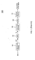
- FIG. 1 shows a simplified block diagram of one implementation of a prior-art OFDM transmitter 100.
- Transmitter 100 receives digital input data and converts the data into analog OFDM signals for transmission. Conversion of the data occurs through sequential steps of data symbol mapping 102 , inverse fast Fourier transform (IFFT) processing 104 , cyclic prefix appending 106 , digital-to-analog conversion (DAC) 108 , and spectral shaping 110 .
- IFFT inverse fast Fourier transform
- DAC digital-to-analog conversion
- Data symbol mapping block 102 receives binary bits of data, which are divided into groups of finite length. One or more data symbols a[n] are created for each group of bits, using any one of a number of modulation techniques commonly known in the art, such as differential quadrature phase-shift-keying (DQPSK) or quadrature amplitude modulation (QAM). The length of each group and thus the number of input data bits per data symbol is determined by the modulation technique employed.
- DQPSK differential quadrature phase-shift-keying
- QAM quadrature amplitude modulation
- IFFT 104 subsequently applies each set of N data symbols a[n] to a set of N subcarriers, which are numbered from 0 to N -1, where one data symbol a[n] is paired with each subcarrier.
- the subcarriers employed by OFDM are arranged orthogonally to one another, so that each subcarrier can be distinguished without intersymbol interference.
- Each set k of N data symbol a[n] and subcarrier pairs is then converted by IFFT 104 from frequency-domain representations into a time-domain OFDM symbol S k , consisting of N samples S k [i], where i equals 0 to N- 1.
- the OFDM symbols S k are then prepared for transmission.
- a cyclic prefix is inserted at the beginning of each OFDM symbol S k by cyclic prefix appending 106. This prefix enables the receiver to cope with signal echoes that result from multipath reflections.
- the OFDM symbols and prefixes are converted from digital format to analog format using digital-to-analog converter (DAC) 108 .
- DAC digital-to-analog converter
- the analog output from DAC 108 undergoes spectral shaping by spectral shaping block 110 to produce an OFDM signal for transmission.
- the samples S k [i] of each OFDM symbol S k remain grouped together, and the OFDM symbols S k are transmitted in succession.
- samples S 0 [0] to S 0 [127] of OFDM symbol S 0 are transmitted before samples S 1 [0] to S 1 [127] of OFDM symbol S 1 , which are transmitted before samples S 2 [0] to S 2 [127] of OFDM symbol S 2 .
- FIG. 2 shows a frequency-domain representation of prior-art OFDM symbol S 0 described in the example above.
- Each subcarrier represented by a single waveform, is assigned one data symbol a[n] . Additionally, note that the subcarriers are spaced apart so that the peak of each subcarrier corresponds to a zero level of every other subcarrier. This is representative of the orthogonal nature of the set of subcarriers.
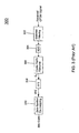
- FIG. 3 shows a simplified block diagram of one implementation of a prior-art OFDM receiver 300 , which reverses the operations performed by OFDM transmitter 100 .
- Receiver 300 receives analog OFDM signals and extracts the original digital data. Extraction occurs through sequential steps of matched filtering 302 , analog-to-digital conversion (ADC) 304 , cyclic prefix removal 306 , fast Fourier transform (FFT) processing 308 , and data symbol demapping 310 .
- ADC analog-to-digital conversion
- FFT fast Fourier transform
- the received OFDM signal is down-converted into a baseband analog signal at the receiver's RF front end.
- the baseband analog signal is filtered by matched filtering block 302 and converted to digital format by ADC 304 .
- synchronization and channel estimation may be performed (not shown).
- cyclic prefix removal block 306 removes the cyclic prefixes from the time-domain OFDM symbols S k .
- Müller, et al., "A Novel Peak Power Reduction Scheme for OFDM,” Proc. of the Int. Symposium on Personal, Indoor and Mobile Radio Communications, pp. 1090-1094, Sept. 1997 teaches an OFDM system that applyies V IDFTs to V frequency-domain subblocks, wherein all of the subcarrier positions in each subblock that are already represented in another subblock are set to zero. After applying the V IDFTs, the resulting V time-domain subblocks multiplied by rotation factors and are combined by summing the subsymbols to generate an OFDM symbol.
- the first samples of the V time-domain subsymbols are summed to generate a first sample of the OFDM symbol
- the second samples of the V time-domain subsymbols are summed to generate a second sample of the OFDM symbol, and so on.
- Multiplying by the rotation factors helps reduce the peak-to-average power ratio of the resulting OFDM symbol.
- summing the V time-domain subsymbols results in an OFDM symbol that has the same number of samples as each V time-domain subsymbol.
- European patent application number EP-1357718-A2 teaches a similar method of generating OFDM symbols.
- the invention is a method according to claim 1.
- the invention is an apparatus according to claim 8.
- the invention is a method according to claim 9.
- the invention is an apparatus according to claim 15.
- Certain embodiments of the present invention relate to combined-OFDM methods and apparatuses for practicing these methods.
- data symbols a [ n ] are divided into groups, where each group is converted into an OFDM subsymbol using an inverse fast Fourier transform. Then, multiple OFDM subsymbols are combined to produce a combined-OFDM symbol.
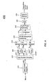
- FIG. 4 shows a simplified block diagram of a combined-OFDM transmitter 400 according to one embodiment of the present invention.
- Transmitter 400 receives digital input data and converts the data into analog combined-OFDM signals for transmission. Conversion of the data occurs through sequential steps of data symbol mapping 402 , data symbol grouping 412 , inverse fast Fourier transform (IFFT) processing 404 , OFDM subsymbol combining 416 , cyclic prefix appending 406 , digital-to-analog conversion (DAC) 408 , and spectral shaping 410.
- IFFT inverse fast Fourier transform
- IFFT 104 receives a set of N data symbols a [ n ] from data symbol mapping block 102 and assigns the N data symbols a [ n ] to N subcarriers.
- the N data symbol a [ n ] and subcarrier pairs are then converted from frequency-domain representations into a time-domain OFDM symbol S k .
- transmitter 400 has data symbol mapping block 402, which performs operations analogous to those of data symbol mapping block 102 of prior-art transmitter 100.
- transmitter 400 has M instances of IFFT 404, M > 1, each instance utilizing N subcarriers.
- a set of N data symbols a[n] is divided into M groups by data symbol grouping 412.
- Each group m numbered consecutively from 0 to M -1 , is then transmitted to a separate instance of IFFT 404.
- Division of data symbols a [ n ] amongst the M groups is performed according to a grouping pattern. This pattern is described further in the example below.
- Each instance of IFFT 404 receives one group m of N M data symbols a [ n ] and assigns the N M data symbols to the N subcarriers. Since the number N M of data symbols a [ n ] in each group m is smaller than the number N of subcarriers per IFFT 404 , not every subcarrier is assigned a data symbol a[n] for modulation. Thus, the number N m of modulated subcarriers per IFFT'404 is equal to N M . Each IFFT 404 then converts the N subcarriers (i.e.
- M instances of IFFT 404 produce M time-domain OFDM subsymbols S m , each subsymbol S m consisting of N samples.
- OFDM subsymbol combining 416 receives M OFDM subsymbols, each containing N samples, from the M instances of IFFT 404.
- the ( N x M ) total samples are combined using an interleaving pattern, to create one type of combined-OFDM symbol, herein referred to as an interleaved-OFDM (IOFDM) symbol.
- IPFDM interleaved-OFDM
- Equation (4) The resulting IOFDM symbol is expressed in Equation (4) below:
- ⁇ [.] denotes a unit impulse sequence. This unit impulse sequence varies depending on the OFDM subsymbol combining (e.g., interleaving) pattern used.
- transmitter 400 performs cyclic prefix appending 406 , digital-to-analog conversion (DAC) 408 , and spectral shaping 410 .
- DAC digital-to-analog conversion
- the 128 data symbols a[n] may be divided into M groups by data symbol grouping block 412 as shown in Table III. TABLE III. GROUPING OF DATA SYMBOLS a[n] IN THE FREQUENCY DOMAIN OF AN IOFDM SIGNAL ACCORDING TO ONE EMBODIMENT Subcarrier Index 0 1 2 3 4 ...
- the first data symbol a[0] is assigned to subcarner 0 in OFDM subsymbol S 0
- the second data symbol a[1] is assigned to subcarrier 1 in the second OFDM subsymbol S 1
- the third data symbol a[2] is assigned to subcarrier 2 in the third OFDM subsymbol S 2
- the fourth data symbol a[3] is assigned to subcarrier 3 in the fourth OFDM subsymbol S 3 .
- This grouping pattern is continued beginning with the fifth data symbol a[4] being assigned to subcarrier 4 in the first OFDM subsymbol S 0 and concluding with the last data symbol a[127] being assigned to subcarrier 127 in the fourth OFDM subsymbol S 3 .
- FIG. 5 further demonstrates the data symbol grouping pattern described in the example above.
- This frequency-domain representation shows each modulated subcarrier N m , represented by a single waveform.
- FIGS. 5 (a), (b), (c), and (d) show the first modulated subcarriers of OFDM subsymbols S 0 , S 1 , S 2 , and S 3 , respectively.
- FIG. 5 (e) shows the frequency-domain representation of the corresponding IOFDM symbol. Note that P( ⁇ ) is the frequency response of spectral shaping block 410.
- samples S m [i] may be interleaved as shown in Table IV to produce an IOFDM symbol X k .
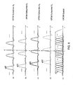
- FIG. 6 further demonstrates the interleaving pattern described in the example above.
- FIGS. 6 (a), (b), (c and (d) represent OFDM subsymbols S 0 , S 1 , S 2 , and S 3 , respectively.
- FIG. 6 (e) represents the interleaved OFDM symbol X k .
- each set of 128 data symbols is transmitted using 128 OFDM samples.
- the IOFDM symbol duration of this example is 4 times longer than the OFDM symbol duration of the corresponding prior-art example.
- an IOFDM symbol X k is more robust against noise effects during transmission than the corresponding prior-art OFDM symbol S k .
- the sample period (T/N) of the IOFDM symbol X k is the same as the sample period of the prior-art OFDM symbol S k .
- the bandwidth of the IOFDM symbol X k is the same as that of the OFDM symbol S k .
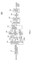
- FIG. 7 shows a simplified block diagram of one implementation of a combined-OFDM receiver 700 , which reverses the operations performed by combined-OFDM transmitter 400 .
- Receiver 700 receives analog combined-OFDM signals and extracts the original digital data. Extraction occurs through sequential steps of matched filtering 702 , analog-to-digital conversion (ADC) 704 , cyclic prefix removal 706 , OFDM subsymbol separating 714 , fast Fourier transform (FFT) processing 708 , data symbol de-grouping and equalization 718 , and data symbol de-mapping 710.
- ADC analog-to-digital conversion
- FFT fast Fourier transform
- receiver 700 down-converts the received signal into a baseband analog signal at the receiver's RF front end. Then, similar to prior-art receiver 300 of FIG. 3 , receiver 700 performs matched filtering 702 , analog-to-digital conversion ADC 704, and cyclic prefix removal 706 . Additionally, synchronization and channel estimation may be performed (not shown).
- OFDM subsymbol separating block 714 separates (e.g., deinterleaves) the digital IOFDM symbols X k to recover the M OFDM subsymbols S m .
- the M OFDM subsymbols S m are subsequently transmitted to the M instances of FFT 708 .
- Each instance of FFT 708 extracts N subcarriers from the corresponding OFDM subsymbol S m to obtain the corresponding group m of data symbols a[n] .
- the M groups of data symbols a[n] are then equalized and de-grouped by data symbol de-grouping and equalization block 718 .
- data symbols a[n] are de-mapped into the original binary bits using conventional data symbol de-mapping block 710 .
- data symbols a[n] were grouped using an interleaving pattern.
- Another grouping pattern using interleaving may be employed for the above IOFDM example in which the first two data symbols ( a [0] and a[1]) are assigned to subcarriers 0 and 1 in OFDM subsymbol S 0 , the third and fourth data symbols ( a[2] and a[3] ) are assigned to subcarriers 2 and 3 in OFDM subsymbol S 1 , the fifth and sixth data symbols ( a[4] and a[5]) are assigned to subcarriers 4 and 5 in OFDM subsymbol S 2 , and the seventh and eighth data symbols ( a[6] and a[7] ) are assigned to subcarriers 6 and 7 in OFDM subsymbol S 3 .
- OFDM subsymbol combining block 416 may assign two consecutive samples S m [i] to IOFDM symbol X(k) at a time.
- OFDM subsymbol combining block 416 may assign S 0 [0] and S 0 [1], followed by S 1 [0] and S 1 [1], followed by S 2 [0] and S 2 [1], followed by S 3 [0] and S 3 [1] to IOFDM symbol X ( k ). This process is then repeated beginning with S 0 [2] and ending with S 3 [127] .
- a vast number of alternative combining patterns using interleaving may be envisioned within the scope of this invention.
- subsymbols S k can be appended to each other without interleaving, such that, samples S 0 [0] to S 0 [127] of subsymbol S 0 are followed by samples S 1 [0] to S 1 [127] of subsymbol S 1 , which are followed by samples S 2 [0] to S 2 [127] of subsymbol S 2 , which are followed by samples S 3 [0] to S 3 [127] of subsymbol S 3 .
- the order in which subsymbols S k are appended may also vary.
- OFDM subsymbols S m or combined-OFDM symbols X k are upsampled by upsamplers 414 or 418, respectively, to increase the data rate.
- the 128 samples S m [i] may be upsampled by 4 (i.e., upsampled by M ), so that the total number of modulated samples transmitted per IOFDM symbol increases from 128 to 512.
- imaging in DAC 408 produces a larger signal bandwidth.
- FIG. 8 graphically demonstrates this imaging in the frequency domain. Note that the modulated subcarriers are repeated at higher frequencies. This phenomenon increases the overall signal bandwidth.
- receiver 700 has downsamplers 712 or 716 , which downsample either the combined-OFDM symbols X k or the OFDM subsymbols S m of the received signal, respectively.
- the present invention has been described using a number of data symbols a[n] that is equal to the number N of subcarriers; however, the present invention is not so limited.
- the number of data symbols a[n] may be fewer than the number N of subcarriers. Therefore, the number N m , of subcarriers modulated with data symbols a[n] per IFFT 404 could be less than N M .
- the excess unmodulated subcarriers could then be used for other purposes such as implementation as guard channels or pilot channels.
- the number M of groups varies.
- the number M of groups i.e., 4 was chosen based on the number N (i.e., 128) of subcarriers such that the number N m of modulated subcarriers per group (i.e., N M ) is an integer (i.e., 32). While it is preferred that the number of data symbols per group N m be an integer, it is not necessary.
- the number M of groups could be 3, in which case each group would not necessarily have the same number of data symbols a[n] .
- the width of the overall frequency spectrum is increased.
- Selecting a number M of groups that is equal to the number N of subcarriers allows for the greatest possible spectrum spreading.
- the frequency spectrum width is decreased.
- Selecting the number M of groups such that M 1, results in the production of a prior-art OFDM signal.
- Combined OFDM therefore, provides a means to construct a variable spreading ratio system according to different applications and/or channel conditions. This spectrum spreading ability allows combined OFDM to be suitable for use in ultra-wideband (UWB) applications. Additionally, due to the wider spectrum of the combined-OFDM signal, lower power operation can be achieved, thereby easing issues of interference compliance.
- the number of IFFT blocks in transmitter 400 and FFT blocks in receiver 700 may vary.
- transmitter 400 might have only one shared IFFT block that receives the M groups of data symbols a[n] in succession and converts the M groups in succession into M subsymbols S m in a time-multiplexed manner.
- OFDM coded OFDM
- piconet channelization methods such as code division multiple access (CDMA) and frequency division multiple access (FDMA) can be used in conjunction with combined OFDM so that multi-piconet performance can be improved.
- CDMA code division multiple access
- FDMA frequency division multiple access
- the present invention has been described as a transmitter and a receiver; however, the present invention may also be implemented as a transceiver. Furthermore, receivers, transmitters, and transceivers may be implemented in a wide variety of applications, including any suitable consumer product or other suitable apparatus. Such apparatuses include devices such as cellular phones and cellular phone base stations.
- the present invention may be implemented as (analog, digital, or a hybrid of both analog and digital) circuit-based processes, including possible implementation as a single integrated circuit (such as an ASIC or an FPGA), a multi-chip module, a single card, or a multi-card circuit pack.
- a single integrated circuit such as an ASIC or an FPGA
- a multi-chip module such as a single card, or a multi-card circuit pack.
- various functions of circuit elements may also be implemented as processing blocks in a software program.
- Such software may be employed in, for example, a digital signal processor, micro-controller, or general-purpose computer.
- the present invention can be embodied in the form of methods and apparatuses for practicing those methods.
- the present invention can also be embodied in the form of program code embodied in tangible media, such as magnetic recording media, optical recording media, solid state memory, floppy diskettes, CD-ROMs, hard drives, or any other machine-readable storage medium, wherein, when the program code is loaded into and executed by a machine, such as a computer, the machine becomes an apparatus for practicing the invention.
- the present invention can also be embodied in the form of program code, for example, whether stored in a storage medium, loaded into and/or executed by a machine, or transmitted over some transmission medium or carrier, such as over electrical wiring or cabling, through fiber optics, or via electromagnetic radiation, wherein, when the program code is loaded into and executed by a machine, such as a computer, the machine becomes an apparatus for practicing the invention.
- program code When implemented on a general-purpose processor, the program code segments combine with the processor to provide a unique device that operates analogously to specific circuits.
- the present invention can also be embodied in the form of a bitstream or other sequence of signal values electrically or optically transmitted through a medium, stored magnetic-field variations in a magnetic recording medium, etc., generated using a method and/or an apparatus of the present invention.
- figure numbers and/or figure reference labels in the claims is intended to identify one or more possible embodiments of the claimed subject matter in order to facilitate the interpretation of the claims. Such use is not to be construed as necessarily limiting the scope of those claims to the embodiments shown in the corresponding figures.
Landscapes
- Engineering & Computer Science (AREA)
- Computer Networks & Wireless Communication (AREA)
- Signal Processing (AREA)
- Physics & Mathematics (AREA)
- Discrete Mathematics (AREA)
- General Physics & Mathematics (AREA)
- Mathematical Physics (AREA)
- Error Detection And Correction (AREA)
- Digital Transmission Methods That Use Modulated Carrier Waves (AREA)
Description
- The present invention relates to signal processing, and more specifically to orthogonal frequency division multiplexing techniques used in signal transmission and reception:
- Orthogonal frequency division multiplexing (OFDM) is a signal processing technology well known in the field of communications. In general, OFDM operates by dividing a frequency spectrum into smaller subbands (a.k.a. subcarriers) and modulating these sub carriers with data symbols.
-
FIG. 1 shows a simplified block diagram of one implementation of a prior-art OFDM transmitter 100.Transmitter 100 receives digital input data and converts the data into analog OFDM signals for transmission. Conversion of the data occurs through sequential steps ofdata symbol mapping 102, inverse fast Fourier transform (IFFT)processing 104, cyclic prefix appending 106, digital-to-analog conversion (DAC) 108, andspectral shaping 110. - Data
symbol mapping block 102 receives binary bits of data, which are divided into groups of finite length. One or more data symbols a[n] are created for each group of bits, using any one of a number of modulation techniques commonly known in the art, such as differential quadrature phase-shift-keying (DQPSK) or quadrature amplitude modulation (QAM). The length of each group and thus the number of input data bits per data symbol is determined by the modulation technique employed. - IFFT 104 subsequently applies each set of N data symbols a[n] to a set of N subcarriers, which are numbered from 0 to N-1, where one data symbol a[n] is paired with each subcarrier. The subcarriers employed by OFDM are arranged orthogonally to one another, so that each subcarrier can be distinguished without intersymbol interference. Each set k of N data symbol a[n] and subcarrier pairs is then converted by IFFT 104 from frequency-domain representations into a time-domain OFDM symbol Sk , consisting of N samples Sk[i], where i equals 0 to N-1. The discrete model for each OFDM symbol Sk may be expressed by Equation (1) as follows:


- The OFDM symbols Sk are then prepared for transmission. First, a cyclic prefix is inserted at the beginning of each OFDM symbol Sk by cyclic prefix appending 106. This prefix enables the receiver to cope with signal echoes that result from multipath reflections. Next, the OFDM symbols and prefixes are converted from digital format to analog format using digital-to-analog converter (DAC) 108. Finally, the analog output from
DAC 108 undergoes spectral shaping byspectral shaping block 110 to produce an OFDM signal for transmission. - As an example of the production of a prior-art OFDM signal, assume that IFFT 104 receives 384 data symbols a[n], where n = 0,...,383, and employs N=128 subcarriers. Since one data symbol a[n] in each set of N data symbols a[n] is assigned to each subcarrier, the number of OFDM symbols Sk generated is equal to 3 (384 data symbols a[n] divided by 128 subcarriers). The grouping of data symbols a[n] in the frequency domain is shown in Table L As shown in Table I, in a prior-art OFDM system, data symbols a[0] to a[127] are assigned to OFDM symbol S0, data symbols a[128] to a[255] are assigned to OFDM symbol S1 , and data symbols a[256] to a[383] are assigned to OFDM symbol S2 .
TABLE I. GROUPING OF DATA SYMBOLS a[n] IN THE FREQUENCY DOMAIN OF A PRIOR-ART OFDM SIGNAL Subcarrier Index 0 1 2 3 ... 127 OFDM Symbol 0 (S0 ) a[0] a[1] a[2] a[3] ... a[127] OFDM Symbol 1 (S1 ) a[128] a[129] a[130] a[131] ... a[255] OFDM Symbol 2 (S2 ) a[256] a[257] A[258] a[259] ... a[383] - Table II shows the grouping of samples Sk[i], where k= 0, 1, 2 and i = 0,...,127, in the time domain after conversion by
FFT 104. In a prior-art OFDM system, the samples Sk[i] of each OFDM symbol Sk remain grouped together, and the OFDM symbols Sk are transmitted in succession. In other words, samples S0[0] to S0[127] of OFDM symbol S0 are transmitted before samples S1[0] to S1[127] of OFDM symbol S1 , which are transmitted before samples S2[0] to S2[127] of OFDM symbol S2 .TABLE II. GROUPING OF SAMPLES Sk[i] IN THE TIME DOMAIN OF A PRIOR-ART OFDM SIGNAL OFDM Symbol S0 OFDM Symbol S1 OFDM Symbol S2 Sample Index 0 1 2 3 ... 127 128 129 130 131 ... 255 256 257 258 259 ... 383 Trans-mitted Data S0[0] S0[1] S0[2] S0[3] ... S0[127] S1[0] S1[1] S1[2] S1[3] ... S1[127] S2[0] S2[1] S2[2] S2[3] ... S2[127] -
FIG. 2 shows a frequency-domain representation of prior-art OFDM symbol S0 described in the example above. Each subcarrier, represented by a single waveform, is assigned one data symbol a[n]. Additionally, note that the subcarriers are spaced apart so that the peak of each subcarrier corresponds to a zero level of every other subcarrier. This is representative of the orthogonal nature of the set of subcarriers. -
FIG. 3 shows a simplified block diagram of one implementation of a prior-art OFDM receiver 300, which reverses the operations performed byOFDM transmitter 100.Receiver 300 receives analog OFDM signals and extracts the original digital data. Extraction occurs through sequential steps of matchedfiltering 302, analog-to-digital conversion (ADC) 304,cyclic prefix removal 306, fast Fourier transform (FFT)processing 308, and data symbol demapping 310. - First, the received OFDM signal is down-converted into a baseband analog signal at the receiver's RF front end. The baseband analog signal is filtered by matched
filtering block 302 and converted to digital format byADC 304. Next, synchronization and channel estimation may be performed (not shown). Then, cyclicprefix removal block 306 removes the cyclic prefixes from the time-domain OFDM symbols Sk . - FFT 308 receives digital OFDM symbols Sk and extracts the N subcarriers from each to obtain data symbols a[n], according to Equation (2) as follows:

block 310 which demodulates the data symbols in accordance with the modulation technique employed bydata symbol mapping 102 ofFIG. 1 . - Müller, et al., "A Novel Peak Power Reduction Scheme for OFDM," Proc. of the Int. Symposium on Personal, Indoor and Mobile Radio Communications, pp. 1090-1094, Sept. 1997, teaches an OFDM system that applyies V IDFTs to V frequency-domain subblocks, wherein all of the subcarrier positions in each subblock that are already represented in another subblock are set to zero. After applying the V IDFTs, the resulting V time-domain subblocks multiplied by rotation factors and are combined by summing the subsymbols to generate an OFDM symbol. Thus, the first samples of the V time-domain subsymbols are summed to generate a first sample of the OFDM symbol, the second samples of the V time-domain subsymbols are summed to generate a second sample of the OFDM symbol, and so on. Multiplying by the rotation factors helps reduce the peak-to-average power ratio of the resulting OFDM symbol. Further, summing the V time-domain subsymbols results in an OFDM symbol that has the same number of samples as each V time-domain subsymbol. European patent application number
EP-1357718-A2 teaches a similar method of generating OFDM symbols. - In one aspect, the invention is a method according to
claim 1. - In another aspect, the invention is an apparatus according to claim 8.
- In a further aspect, the invention is a method according to claim 9.
- In yet another aspect, the invention is an apparatus according to claim 15.
- Other aspects, features, and advantages of the present invention will become more fully apparent from the following detailed description, the appended claims, and the accompanying drawings in which like reference numerals identify similar or identical elements.
-
FIG. 1 shows a simplified block diagram of one possible implementation of a prior-art OFDM transmitter; -
FIG. 2 graphically illustrates a frequency-domain representation of an exemplary prior-art OFDM signal; -
FIG. 3 shows a simplified block diagram of one possible implementation of a prior-art OFDM receiver; -
FIG. 4 shows a simplified block diagram of a combined-OFDM transmitter according to one embodiment of the present invention; -
FIG. 5 graphically illustrates one implementation of a grouping pattern of frequency-domain data symbols according to one embodiment of the present invention; -
FIG. 6 graphically illustrates one implementation of an interleaving pattern of time-domain samples according to one embodiment of the present invention; -
FIG. 7 shows a simplified block diagram of a combined-OFDM receiver according to one embodiment of the present invention; and -
FIG. 8 graphically illustrates the imaging that occurs in the frequency domain of an upsampled combined-OFDM signal according to one embodiment of the present invention. - Certain embodiments of the present invention relate to combined-OFDM methods and apparatuses for practicing these methods. In one such embodiment, data symbols a[n] are divided into groups, where each group is converted into an OFDM subsymbol using an inverse fast Fourier transform. Then, multiple OFDM subsymbols are combined to produce a combined-OFDM symbol.
-
FIG. 4 shows a simplified block diagram of a combined-OFDM transmitter 400 according to one embodiment of the present invention.Transmitter 400 receives digital input data and converts the data into analog combined-OFDM signals for transmission. Conversion of the data occurs through sequential steps ofdata symbol mapping 402,data symbol grouping 412, inverse fast Fourier transform (IFFT) processing 404, OFDM subsymbol combining 416, cyclic prefix appending 406, digital-to-analog conversion (DAC) 408, andspectral shaping 410. - In prior-
art transmitter 100 ofFIG. 1 ,IFFT 104 receives a set of N data symbols a[n] from datasymbol mapping block 102 and assigns the N data symbols a[n] to N subcarriers. The N data symbol a[n] and subcarrier pairs are then converted from frequency-domain representations into a time-domain OFDM symbol Sk . According to the embodiment ofFIG. 4 ,transmitter 400 has datasymbol mapping block 402, which performs operations analogous to those of datasymbol mapping block 102 of prior-art transmitter 100. Additionally,transmitter 400 has M instances ofIFFT 404, M > 1, each instance utilizing N subcarriers. A set of N data symbols a[n] is divided into M groups bydata symbol grouping 412. Each group m, numbered consecutively from 0 to M-1, is then transmitted to a separate instance ofIFFT 404. Division of data symbols a[n] amongst the M groups is performed according to a grouping pattern. This pattern is described further in the example below. - Each instance of
IFFT 404 receives one group m of


IFFT 404 , not every subcarrier is assigned a data symbol a[n] for modulation. Thus, the number Nm of modulated subcarriers per IFFT'404 is equal to
IFFT 404 then converts the N subcarriers (i.e. the Nm modulated subcarriers and (N - Nm ) unmodulated subcarriers) from frequency-domain representations into a time-domain OFDM subsymbol Sm . As such, M instances ofIFFT 404 produce M time-domain OFDM subsymbols Sm , each subsymbol Sm consisting of N samples. The discrete model for each OFDM subsymbol Sm , may be expressed by Equation (3) as follows:

- Next, OFDM subsymbol combining 416 receives M OFDM subsymbols, each containing N samples, from the M instances of
IFFT 404. According to this embodiment, the (N x M) total samples are combined using an interleaving pattern, to create one type of combined-OFDM symbol, herein referred to as an interleaved-OFDM (IOFDM) symbol. This interleaving pattern is discussed further in the example below. The resulting IOFDM symbol is expressed in Equation (4) below:
- The IOFDM symbols Xk are then prepared for transmission. Similar to prior-
art transmitter 100 ofFIG. 1 ,transmitter 400 performs cyclic prefix appending 406, digital-to-analog conversion (DAC) 408, andspectral shaping 410. - As an example of an IOFDM signal according to this embodiment, assume that data
symbol grouping block 412 receives 128 data symbols a[n], n = 0,..., 127, and each instance ofIFFT 404 employs N=128 subcarriers. Also, assume that the number M of groups is chosen to be 4. The 128 data symbols a[n] may be divided into M groups by datasymbol grouping block 412 as shown in Table III.TABLE III. GROUPING OF DATA SYMBOLS a[n] IN THE FREQUENCY DOMAIN OF AN IOFDM SIGNAL ACCORDING TO ONE EMBODIMENT Subcarrier Index 0 1 2 3 4 ... 127 OFDM Subsymbol 0 (S0 ) a[0] a[4] ... OFDM Subsymbol 1 (S1 ) a[1] ... OFDM Subsymbol 2 (S2 ) a[2] ... OFDM Subsymbol 3 (S3 ) a[3] ... a[127] subcarner 0 in OFDM subsymbol S0, the second data symbol a[1] is assigned tosubcarrier 1 in the second OFDM subsymbol S1, the third data symbol a[2] is assigned tosubcarrier 2 in the third OFDM subsymbol S2 , and the fourth data symbol a[3] is assigned tosubcarrier 3 in the fourth OFDM subsymbol S3. This grouping pattern is continued beginning with the fifth data symbol a[4] being assigned to subcarrier 4 in the first OFDM subsymbol S0 and concluding with the last data symbol a[127] being assigned tosubcarrier 127 in the fourth OFDM subsymbol S3 . -
FIG. 5 further demonstrates the data symbol grouping pattern described in the example above. This frequency-domain representation shows each modulated subcarrier Nm, represented by a single waveform.FIGS. 5 (a), (b), (c), and (d) show the first modulated subcarriers of OFDM subsymbols S0, S1, S2, and S3 , respectively.FIG. 5 (e) shows the frequency-domain representation of the corresponding IOFDM symbol. Note that P(ƒ) is the frequency response ofspectral shaping block 410. - After conversion from frequency-domain representations into time-domain OFDM subsymbols Sm by the 4 instances of
IFFT 404, samples Sm[i] may be interleaved as shown in Table IV to produce an IOFDM symbol Xk .TABLE IV. GROUPING OF SAMPLES Sm[i] IN THE TIME DOMAIN ACCORDING TO ONE EMBODIMENT IOFDM Symbol Xk(q), q = 0,..., 511 Sample Index q 0 1 2 3 4 5 6 7 8 9 10 11 ... 508 509 510 511 Trans-mitted Data S0[0] S1[0] S2[0] S3[0] S0[1] S1[1] S2[1] S 3 [1] S0[2] S1[2] S2[2] S3[2] ... S0[127] S1[127] S2[127] S3[127] -
FIG. 6 further demonstrates the interleaving pattern described in the example above.FIGS. 6 (a), (b), (c and (d) represent OFDM subsymbols S0, S1, S2, and S3 , respectively.FIG. 6 (e) represents the interleaved OFDM symbol Xk . - According to the exemplary IOFDM symbol given above, 512 samples Xk[q], where q = 0,...,511, are transmitted for each set of 128 data symbols a[n]. This is in contrast to the example provided for prior-
art OFDM transmitter 100 in the background section, where each set of 128 data symbols is transmitted using 128 OFDM samples. Thus, the IOFDM symbol duration of this example is 4 times longer than the OFDM symbol duration of the corresponding prior-art example. On the other hand, an IOFDM symbol Xk is more robust against noise effects during transmission than the corresponding prior-art OFDM symbol Sk. In addition, the sample period (T/N) of the IOFDM symbol Xk is the same as the sample period of the prior-art OFDM symbol Sk. Thus, the bandwidth of the IOFDM symbol Xk is the same as that of the OFDM symbol Sk. -
FIG. 7 shows a simplified block diagram of one implementation of a combined-OFDM receiver 700, which reverses the operations performed by combined-OFDM transmitter 400.Receiver 700 receives analog combined-OFDM signals and extracts the original digital data. Extraction occurs through sequential steps of matched filtering 702, analog-to-digital conversion (ADC) 704,cyclic prefix removal 706, OFDM subsymbol separating 714, fast Fourier transform (FFT) processing 708, data symbol de-grouping andequalization 718, anddata symbol de-mapping 710. - First,
receiver 700 down-converts the received signal into a baseband analog signal at the receiver's RF front end. Then, similar to prior-art receiver 300 ofFIG. 3 ,receiver 700 performs matched filtering 702, analog-to-digital conversion ADC 704, andcyclic prefix removal 706. Additionally, synchronization and channel estimation may be performed (not shown). - OFDM
subsymbol separating block 714 separates (e.g., deinterleaves) the digital IOFDM symbols Xk to recover the M OFDM subsymbols Sm. The M OFDM subsymbols Sm are subsequently transmitted to the M instances ofFFT 708. Each instance ofFFT 708 extracts N subcarriers from the corresponding OFDM subsymbol Sm to obtain the corresponding group m of data symbols a[n]. The M groups of data symbols a[n] are then equalized and de-grouped by data symbol de-grouping andequalization block 718. Finally, data symbols a[n] are de-mapped into the original binary bits using conventional data symbolde-mapping block 710. - Various embodiments of the present invention may be envisioned in which alternative grouping patterns are employed. In the IOFDM example above, data symbols a[n] were grouped using an interleaving pattern. Another grouping pattern using interleaving may be employed for the above IOFDM example in which the first two data symbols (a [0] and a[1]) are assigned to
subcarriers subcarriers subcarrier 126 and 127 in OFDM subsymbol S3 . A vast number of alternative grouping patterns may be envisioned within the scope of this invention. - Various embodiments of the present invention may also be envisioned in which alternative combining patterns using interleaving are employed. In one such alternative to the IOFDM example above, OFDM
subsymbol combining block 416 may assign two consecutive samples Sm[i] to IOFDM symbol X(k) at a time. In other words, OFDMsubsymbol combining block 416 may assign S0[0] and S0[1], followed by S1[0] and S1[1], followed by S2[0] and S2[1], followed by S3[0] and S3[1] to IOFDM symbol X(k). This process is then repeated beginning with S0[2] and ending with S3[127]. A vast number of alternative combining patterns using interleaving may be envisioned within the scope of this invention. - Furthermore, the above mentioned examples demonstrate one type of combined-OFDM symbol, referred to as an IOFDM symbol. In another type of combined-OFDM symbol, subsymbols Sk can be appended to each other without interleaving, such that, samples S0[0] to S0[127] of subsymbol S0 are followed by samples S1[0] to S1[127] of subsymbol S1, which are followed by samples S2[0] to S2[127] of subsymbol S2 , which are followed by samples S3[0] to S3[127] of subsymbol S3 . The order in which subsymbols Sk are appended may also vary.
- Further embodiments of the present invention may be envisioned in which the combined-OFDM symbol duration is the same as the corresponding prior-art OFDM symbol duration. In such embodiments, OFDM subsymbols Sm or combined-OFDM symbols Xk are upsampled by
upsamplers DAC 408 produces a larger signal bandwidth. The resulting upsampled IOFDM signal may be represented by Equation (5) as follows:

FIG. 8 graphically demonstrates this imaging in the frequency domain. Note that the modulated subcarriers are repeated at higher frequencies. This phenomenon increases the overall signal bandwidth. Additionally, in order to accommodate upsampling,receiver 700 hasdownsamplers - The present invention has been described using a number of data symbols a[n] that is equal to the number N of subcarriers; however, the present invention is not so limited. The number of data symbols a[n] may be fewer than the number N of subcarriers. Therefore, the number Nm, of subcarriers modulated with data symbols a[n] per
IFFT 404 could be less than
- Additional embodiments of the present invention may be envisioned in which the number M of groups varies. In the above-mentioned IOFDM example, the number M of groups (i.e., 4) was chosen based on the number N (i.e., 128) of subcarriers such that the number Nm of modulated subcarriers per group (i.e.,

- In yet other embodiments, the number of IFFT blocks in
transmitter 400 and FFT blocks inreceiver 700 may vary. For instance, in the above-mentioned IOFDM example,transmitter 400 might have only one shared IFFT block that receives the M groups of data symbols a[n] in succession and converts the M groups in succession into M subsymbols Sm in a time-multiplexed manner. - Other elements of OFDM are supported by this invention. For example, this invention may be implemented using coded OFDM (COFDM). Additionally, piconet channelization methods such as code division multiple access (CDMA) and frequency division multiple access (FDMA) can be used in conjunction with combined OFDM so that multi-piconet performance can be improved.
- The present invention has been described as a transmitter and a receiver; however, the present invention may also be implemented as a transceiver. Furthermore, receivers, transmitters, and transceivers may be implemented in a wide variety of applications, including any suitable consumer product or other suitable apparatus. Such apparatuses include devices such as cellular phones and cellular phone base stations.
- The present invention may be implemented as (analog, digital, or a hybrid of both analog and digital) circuit-based processes, including possible implementation as a single integrated circuit (such as an ASIC or an FPGA), a multi-chip module, a single card, or a multi-card circuit pack. As would be apparent to one skilled in the art, various functions of circuit elements may also be implemented as processing blocks in a software program. Such software may be employed in, for example, a digital signal processor, micro-controller, or general-purpose computer.
- The present invention can be embodied in the form of methods and apparatuses for practicing those methods. The present invention can also be embodied in the form of program code embodied in tangible media, such as magnetic recording media, optical recording media, solid state memory, floppy diskettes, CD-ROMs, hard drives, or any other machine-readable storage medium, wherein, when the program code is loaded into and executed by a machine, such as a computer, the machine becomes an apparatus for practicing the invention. The present invention can also be embodied in the form of program code, for example, whether stored in a storage medium, loaded into and/or executed by a machine, or transmitted over some transmission medium or carrier, such as over electrical wiring or cabling, through fiber optics, or via electromagnetic radiation, wherein, when the program code is loaded into and executed by a machine, such as a computer, the machine becomes an apparatus for practicing the invention. When implemented on a general-purpose processor, the program code segments combine with the processor to provide a unique device that operates analogously to specific circuits.
- The present invention can also be embodied in the form of a bitstream or other sequence of signal values electrically or optically transmitted through a medium, stored magnetic-field variations in a magnetic recording medium, etc., generated using a method and/or an apparatus of the present invention.
- Unless explicitly stated otherwise, each numerical value and range should be interpreted as being approximate as if the word "about" or "approximately" preceded the value of the value or range.
- It will be further understood that various changes in the details, materials, and arrangements of the parts which have been described and illustrated in order to explain the nature of this invention may be made by those skilled in the art without departing from the scope of the invention as expressed in the following claims. For example, various equalization techniques commonly known in the art may be employed in
receiver 700. As another example, methods other than cyclic prefix appending might be employed, including use of a zero pad. - The use of figure numbers and/or figure reference labels in the claims is intended to identify one or more possible embodiments of the claimed subject matter in order to facilitate the interpretation of the claims. Such use is not to be construed as necessarily limiting the scope of those claims to the embodiments shown in the corresponding figures.
- It should be understood that the steps of the exemplary methods set forth herein are not necessarily required to be performed in the order described, and the order of the steps of such methods should be understood to be merely exemplary. Likewise, additional steps may be included in such methods, and certain steps may be omitted or combined, in methods consistent with various embodiments of the present invention.
- Although the elements in the following method claims, if any, are recited in a particular sequence with corresponding labeling, unless the claim recitations otherwise imply a particular sequence for implementing some or all of those elements, those elements are not necessarily intended to be limited to being implemented in that particular sequence.
- Reference herein to "one embodiment" or "an embodiment" means that a particular feature, structure, or characteristic described in connection with the embodiment can be included in at least one embodiment of the invention. The appearances of the phrase "in one embodiment" in various places in the specification are not necessarily all referring to the same embodiment, nor are separate or alternative embodiments necessarily mutually exclusive of other embodiments. The same applies to the term "implementation."
Claims (15)
- A method for modulating a set of data symbols into a combined modulated symbol, the method comprising:a) dividing (412) the set of data symbols into M groups of data symbols, M>1;b) transforming (404) each group of data symbols into a time-domain subsymbol to produce M time-domain subsymbols, wherein:the transformation of each group of data symbols is based on a set of subcarriers, of which only a subset of the subcarriers is modulated by the group of data symbols;each data symbol in each group modulates a different subcarrier in a corresponding subset of the subcarriers; andno two subsets of subcarriers have a subcarrier in common; and CHARACTERIZED BY the method further comprising:c) combining (416) the M time-domain subsymbols to form the combined modulated symbol such that the combined modulated symbol has a duration that is longer than each time-domain subsymbol.
- The invention of claim 1, wherein the total number of subcarriers in the M subsets of subcarriers is equal to the number of subcarriers in the set of subcarriers.
- The invention of claim 1, wherein step b) comprises, for each subset of modulated subcarriers, transforming both the subset of modulated subcarriers and one or more unmodulated subcarriers to form the corresponding time-domain subsymbol.
- The invention of claim 3, wherein for each group of data symbols, the sum of 1) the number of the modulated subcarriers and 2) the number of the one or more unmodulated subcarriers is equal to the total number of subcarriers in the set.
- The invention of claim 1, wherein:each time-domain subsymbol is represented by a plurality of time-domain samples; andstep c) comprises interleaving the time-domain samples of the M subsymbols to form a sequence of interleaved time-domain samples for the combined modulated symbol.
- The invention of claim 1, wherein step c) comprises generating an upsampled combined modulated symbol by either i) upsampling (414) the M time-domain subsymbols prior to the combining or ii) upsampling the combined modulated symbol after the combining.
- The invention of claim 1, wherein:the transformation is an inverse fast Fourier transformation (IFFT);each time-domain subsymbol is an OFDM subsymbol; andthe combined modulated symbol is a combined OFDM symbol.
- Apparatus comprising a transmitter (400) for modulating a set of data symbols into a combined modulated symbol, the transmitter comprising:a data symbol grouper (412) adapted to divide the set of data symbols into M groups of data symbols, M>1;one or more transforms (404) adapted to transform each group of data symbols into a time-domain subsymbol, wherein:the transformation of each group of data symbols is based on a set of subcarriers, of which only a subset of the subcarriers is modulated by the group of data symbols;each data symbol in each group modulates a different subcarrier in a corresponding subset of the subcarriers; andno two subsets of subcarriers have a subcarrier in common; and_CHARACTERIZED BY the transmitter further comprising:a subsymbol combiner (416) adapted to combine the M time-domain subsymbols to form the combined modulated symbol such that the combined modulated symbol has a duration that is longer than each time-domain subsymbol.
- A method for demodulating a combined modulated symbol into a set of demodulated data symbols, CHARACTERIZED BY the method comprising:a) separating (714) the combined modulated symbol into M time-domain subsymbols, M>1, such that each time-domain subsymbol has a duration that is shorter than the combined modulated symbol;b) transforming (708) each time-domain subsymbol into a group of demodulated data symbols, wherein:the transformation of each time-domain subsymbol is based on a set of subcarriers, of which only a subset of the subcarriers is modulated by the group of demodulated data symbols;each demodulated data symbol in each group modulates a different subcarrier in a corresponding subset of the sub carriers; andno two subsets of subcarriers have a subcarrier in common; andc) de-grouping (718) the M groups of demodulated data symbols to generate the set of demodulated data symbols.
- The invention of claim 9, wherein:the combined modulated symbol comprises a sequence of interleaved time-domain samples; andstep a) comprises de-interleaving the interleaved time-domain samples to obtain the M time-domain subsymbols.
- The invention of claim 9, wherein the total number of subcarriers in the M subsets of subcarriers is equal to the number of subcarriers in the set of subcarriers.
- The invention of claim 9, wherein step b) comprises, for each subset of modulated subcarriers, transforming both the subset of modulated subcarriers and one or more unmodulated subcarriers to form the corresponding group of demodulated data symbols.
- The invention of claim 12, wherein for each group of demodulated data symbols, the sum of 1) the number of the modulated subcarriers and 2) the number of the one or more unmodulated subcarriers is equal to the total number of subcarriers in the set.
- The invention of claim 9, wherein:the transformation is a fast Fourier transformation (FFT);each time-domain subsymbol is an OFDM subsymbol; andthe combined modulated symbol is a combined OFDM symbol.
- Apparatus comprising a receiver (700) for demodulating a combined modulated symbol into a set of demodulated data symbols, CHARACTERIZED BY the receiver comprising:a subsymbol separator (714) adapted to separate the combined modulated symbol into M time-domain subsymbols, M>1, such that each time-domain subsymbol has a duration that is shorter than the combined modulated symbol;one or more transforms (708) adapted to transform each time-domain subsymbol into a group of demodulated data symbols, wherein:the transformation of each time-domain subsymbol is based on a set of subcarriers, of which only a subset of the subcarriers is modulated by the group of demodulated data symbols;each demodulated data symbol in each group modulates a different subcarrier in a corresponding subset of the subcarriers; andno two subsets of subcarriers have a subcarrier in common; anda data symbol de-grouper (718) adapted to de-group the M groups of demodulated data symbols to generate the set of demodulated data symbols.
Applications Claiming Priority (2)
| Application Number | Priority Date | Filing Date | Title |
|---|---|---|---|
| US81366706P | 2006-06-14 | 2006-06-14 | |
| PCT/US2006/045578 WO2007145660A1 (en) | 2006-06-14 | 2006-11-29 | Orthogonal frequency division multiplexing using subsymbol processing |
Publications (2)
| Publication Number | Publication Date |
|---|---|
| EP2033393A1 EP2033393A1 (en) | 2009-03-11 |
| EP2033393B1 true EP2033393B1 (en) | 2014-01-22 |
Family
ID=37876917
Family Applications (1)
| Application Number | Title | Priority Date | Filing Date |
|---|---|---|---|
| EP06838501.2A Not-in-force EP2033393B1 (en) | 2006-06-14 | 2006-11-29 | Orthogonal frequency division multiplexing using subsymbol processing |
Country Status (6)
| Country | Link |
|---|---|
| US (1) | US8406323B2 (en) |
| EP (1) | EP2033393B1 (en) |
| JP (1) | JP4959791B2 (en) |
| KR (1) | KR101298511B1 (en) |
| CN (1) | CN101461203B (en) |
| WO (1) | WO2007145660A1 (en) |
Families Citing this family (25)
| Publication number | Priority date | Publication date | Assignee | Title |
|---|---|---|---|---|
| US20030081538A1 (en) * | 2001-10-18 | 2003-05-01 | Walton Jay R. | Multiple-access hybrid OFDM-CDMA system |
| US7844280B2 (en) * | 2006-12-12 | 2010-11-30 | Trueposition, Inc. | Location of wideband OFDM transmitters with limited receiver bandwidth |
| US7797000B2 (en) * | 2006-12-01 | 2010-09-14 | Trueposition, Inc. | System for automatically determining cell transmitter parameters to facilitate the location of wireless devices |
| JP4548487B2 (en) * | 2008-01-11 | 2010-09-22 | ソニー株式会社 | Transmission device, communication system, transmission method, and program |
| CN102714648B (en) * | 2010-07-09 | 2015-07-15 | 联发科技(新加坡)私人有限公司 | WLAN device and method thereof |
| FR2977066B1 (en) * | 2011-06-27 | 2016-12-30 | Schneider Electric Ind Sas | ELECTRICAL PROTECTION APPARATUS COMPRISING AT LEAST ONE CUTTING MODULE CONTROLLED BY AN ELECTROMAGNETIC COIL CONTROL DEVICE |
| US8731413B1 (en) * | 2012-01-23 | 2014-05-20 | Viasat, Inc. | DAC-based optical modulator and demodulator |
| EP2627028B1 (en) * | 2012-02-08 | 2020-11-04 | Vodafone IP Licensing limited | Resource allocation in an OFDM communication system |
| EP2916506B1 (en) * | 2014-03-07 | 2019-07-31 | Vodafone GmbH | Walsh-Hadamard transformed GFDM radio transmission |
| CA2956957C (en) | 2014-08-07 | 2019-02-12 | ONE Media, LLC | Dynamic configuration of a flexible orthogonal frequency division multiplexing phy transport data frame |
| CA2955611C (en) | 2014-08-07 | 2022-03-22 | Coherent Logix, Incorporated | Multi-partition radio frames |
| JP6502764B2 (en) * | 2015-02-10 | 2019-04-17 | 日本放送協会 | Transmitter, receiver, and semiconductor chip |
| CN105024878B (en) * | 2015-06-30 | 2018-07-20 | 芯海科技(深圳)股份有限公司 | A kind of time-delay measuring method of OFDM group systems |
| EP3326342B1 (en) * | 2015-07-20 | 2019-09-25 | Telefonaktiebolaget LM Ericsson (publ) | Transceiver architecture that maintains legacy timing by inserting and removing cyclic prefix at legacy sampling rate |
| EP3206353B1 (en) * | 2016-02-09 | 2020-02-05 | Technische Universität München | Filter banks and methods for operating filter banks |
| CN107302416A (en) * | 2016-04-15 | 2017-10-27 | 索尼公司 | Apparatus and method, Soft Inform ation estimator for the sending and receiving end of wireless communication system |
| EP3445011B1 (en) | 2016-05-11 | 2022-01-26 | Huawei Technologies Co., Ltd. | Signal processing methods and transmitter |
| CN107370704A (en) * | 2016-05-13 | 2017-11-21 | 财团法人工业技术研究院 | Wireless communication apparatus and wireless signal generating method |
| FR3052616B1 (en) * | 2016-06-09 | 2018-06-22 | B-Com | METHOD FOR GENERATING A MODULATED SIGNAL IN PULSE POSITION, DEMODULATION METHOD, COMPUTER PROGAMET PRODUCT AND CORRESPONDING DEVICES |
| WO2018128579A1 (en) * | 2017-01-05 | 2018-07-12 | Telefonaktiebolaget Lm Ericsson (Publ) | Narrowband physical random access channel (nprach) for extended range |
| CN109510791A (en) * | 2017-09-15 | 2019-03-22 | 华为技术有限公司 | Transmission method and transmitting device |
| US10979270B2 (en) * | 2018-03-09 | 2021-04-13 | Infinera Corporation | Scalable synthesis of signals of high symbol rate using lower symbol rate DSPS |
| CN113055067B (en) * | 2019-12-27 | 2024-04-26 | 中兴通讯股份有限公司 | Downlink signal processing method, device and base station |
| CN115299016A (en) * | 2020-02-14 | 2022-11-04 | 华为技术有限公司 | Multi-rate crest factor reduction |
| US11595237B1 (en) * | 2022-05-03 | 2023-02-28 | Qualcomm Incorporated | Peak reduction tone allocation |
Family Cites Families (9)
| Publication number | Priority date | Publication date | Assignee | Title |
|---|---|---|---|---|
| DE19635813A1 (en) * | 1996-09-04 | 1998-03-05 | Johannes Prof Dr Ing Huber | Process for reducing the peak value factor in digital transmission processes |
| US7206350B2 (en) | 2001-06-11 | 2007-04-17 | Unique Broadband Systems, Inc. | OFDM multiple sub-channel communication system |
| JP3649179B2 (en) * | 2001-12-04 | 2005-05-18 | 住友電気工業株式会社 | Mobile communication device |
| KR100754721B1 (en) * | 2002-04-26 | 2007-09-03 | 삼성전자주식회사 | Apparatus and method for transmitting and receiving multiplexed data in an orthogonal frequency division multiplexing communication system |
| KR20040021322A (en) * | 2002-09-03 | 2004-03-10 | 삼성전자주식회사 | Optical disc drive |
| KR20040032683A (en) * | 2002-10-10 | 2004-04-17 | 엘지전자 주식회사 | Fast fourier transform apparatus for wireless lan system |
| US20040081131A1 (en) * | 2002-10-25 | 2004-04-29 | Walton Jay Rod | OFDM communication system with multiple OFDM symbol sizes |
| EP1678906A1 (en) | 2003-10-24 | 2006-07-12 | QUALCOMM Incorporated | Frequency division multiplexing of multiple data streams in a wireless multi-carrier communication system |
| JP4703135B2 (en) * | 2004-05-25 | 2011-06-15 | 株式会社エヌ・ティ・ティ・ドコモ | Transmitter and transmission control method |
-
2006
- 2006-11-29 KR KR1020087031967A patent/KR101298511B1/en not_active IP Right Cessation
- 2006-11-29 CN CN2006800549578A patent/CN101461203B/en not_active Expired - Fee Related
- 2006-11-29 US US12/299,348 patent/US8406323B2/en active Active
- 2006-11-29 EP EP06838501.2A patent/EP2033393B1/en not_active Not-in-force
- 2006-11-29 JP JP2009515379A patent/JP4959791B2/en not_active Expired - Fee Related
- 2006-11-29 WO PCT/US2006/045578 patent/WO2007145660A1/en active Application Filing
Also Published As
| Publication number | Publication date |
|---|---|
| CN101461203B (en) | 2013-03-27 |
| US20090207926A1 (en) | 2009-08-20 |
| WO2007145660A1 (en) | 2007-12-21 |
| JP2009540742A (en) | 2009-11-19 |
| CN101461203A (en) | 2009-06-17 |
| KR101298511B1 (en) | 2013-08-22 |
| JP4959791B2 (en) | 2012-06-27 |
| KR20090021296A (en) | 2009-03-02 |
| US8406323B2 (en) | 2013-03-26 |
| EP2033393A1 (en) | 2009-03-11 |
Similar Documents
| Publication | Publication Date | Title |
|---|---|---|
| EP2033393B1 (en) | Orthogonal frequency division multiplexing using subsymbol processing | |
| EP2200244B1 (en) | Method and apparatus for multi-carrier frequency division multiplexing transmission | |
| Michailow et al. | Generalized frequency division multiplexing: Analysis of an alternative multi-carrier technique for next generation cellular systems | |
| US8484272B2 (en) | Unified pulse shaping for multi-carrier and single-carrier waveforms | |
| AU2004247167B2 (en) | Apparatus and method for transmitting and receiving a pilot pattern for identification of a base station in an OFDM communication system | |
| CN1913515B (en) | Data communication method based on orthogonal frequency division multiple access | |
| US7948868B2 (en) | Method and arrangement relating to the insertion of pilot tones in the frequency domain in SC-FDMA | |
| US10348544B2 (en) | Method and device for controlling power in multi-carrier communication system | |
| KR20190006966A (en) | System, apparatus and method for communicating data with a circular pulse waveform | |
| US10116479B2 (en) | Apparatus and operating method for controlling peak to average power ratio of signal in wireless communication system | |
| CN101090386A (en) | Block transmission system frequency field demodulation device based on filter set and its method | |
| CN105049386A (en) | Active interference elimination method in UFMC system | |
| JP4633054B2 (en) | Method and transmitter for communicating ultra-wideband signals using orthogonal frequency division multiplexing modulation | |
| CN1925474B (en) | Single carrier frequency-division multi-address transmitting, receiving device based on multiple subband wave filter set and method thereof | |
| US20020168022A1 (en) | Data communication apparatus and method based on orthogonal frequency division multiple access | |
| Baig et al. | A novel precoding based hybrid MC/SC radio access system for PAPR reduction in layered OFDMA of LTE-Advanced | |
| Waldhauser et al. | Multicarrier systems and filter banks | |
| Kumar | BER analysis in Wavelet based SC-FDMA for LTE uplink transmission | |
| Li et al. | Simulation and analysis of GFDM system performance | |
| Rajeswaran et al. | OFDM receiver design and characterization with reduction of PAPR | |
| Augustine et al. | Development of a Novel Feedback Filtered Orthogonal Frequency Division Multiplexing Scheme for 5G Network and Beyond | |
| Dumari et al. | Research Article BER and PSD Improvement of FBMC with Higher Order QAM Using Hermite Filter for 5G Wireless Communication and beyond | |
| Padmavathi et al. | Analysis of Multi Carrier Modulation Techniques for 5G Physical Layer Communications Estimation of KPI | |
| Michailow et al. | Generalized Frequency Division Multiplexing: An Alternative Multi-Carrier Technique for Next Generation Cellular Systems | |
| Krall et al. | Parallel OFDM signal generation for UWB systems |
Legal Events
| Date | Code | Title | Description |
|---|---|---|---|
| PUAI | Public reference made under article 153(3) epc to a published international application that has entered the european phase |
Free format text: ORIGINAL CODE: 0009012 |
|
| 17P | Request for examination filed |
Effective date: 20090114 |
|
| AK | Designated contracting states |
Kind code of ref document: A1 Designated state(s): AT BE BG CH CY CZ DE DK EE ES FI FR GB GR HU IE IS IT LI LT LU LV MC NL PL PT RO SE SI SK TR |
|
| AX | Request for extension of the european patent |
Extension state: AL BA HR MK RS |
|
| DAX | Request for extension of the european patent (deleted) | ||
| RBV | Designated contracting states (corrected) |
Designated state(s): CH FI FR GB LI SE |
|
| REG | Reference to a national code |
Ref country code: DE Ref legal event code: 8566 |
|
| 17Q | First examination report despatched |
Effective date: 20110713 |
|
| GRAP | Despatch of communication of intention to grant a patent |
Free format text: ORIGINAL CODE: EPIDOSNIGR1 |
|
| INTG | Intention to grant announced |
Effective date: 20130910 |
|
| GRAS | Grant fee paid |
Free format text: ORIGINAL CODE: EPIDOSNIGR3 |
|
| GRAA | (expected) grant |
Free format text: ORIGINAL CODE: 0009210 |
|
| AK | Designated contracting states |
Kind code of ref document: B1 Designated state(s): CH FI FR GB LI SE |
|
| REG | Reference to a national code |
Ref country code: GB Ref legal event code: FG4D |
|
| REG | Reference to a national code |
Ref country code: CH Ref legal event code: EP |
|
| REG | Reference to a national code |
Ref country code: SE Ref legal event code: TRGR |
|
| REG | Reference to a national code |
Ref country code: CH Ref legal event code: NV Representative=s name: BOVARD AG, CH |
|
| PLBE | No opposition filed within time limit |
Free format text: ORIGINAL CODE: 0009261 |
|
| STAA | Information on the status of an ep patent application or granted ep patent |
Free format text: STATUS: NO OPPOSITION FILED WITHIN TIME LIMIT |
|
| 26N | No opposition filed |
Effective date: 20141023 |
|
| REG | Reference to a national code |
Ref country code: SE Ref legal event code: EUG Ref country code: CH Ref legal event code: PL |
|
| PG25 | Lapsed in a contracting state [announced via postgrant information from national office to epo] |
Ref country code: CH Free format text: LAPSE BECAUSE OF NON-PAYMENT OF DUE FEES Effective date: 20141130 Ref country code: FI Free format text: LAPSE BECAUSE OF NON-PAYMENT OF DUE FEES Effective date: 20141129 Ref country code: LI Free format text: LAPSE BECAUSE OF NON-PAYMENT OF DUE FEES Effective date: 20141130 Ref country code: SE Free format text: LAPSE BECAUSE OF NON-PAYMENT OF DUE FEES Effective date: 20141130 |
|
| REG | Reference to a national code |
Ref country code: FR Ref legal event code: ST Effective date: 20150731 |
|
| PG25 | Lapsed in a contracting state [announced via postgrant information from national office to epo] |
Ref country code: FR Free format text: LAPSE BECAUSE OF NON-PAYMENT OF DUE FEES Effective date: 20141201 |
|
| PGFP | Annual fee paid to national office [announced via postgrant information from national office to epo] |
Ref country code: GB Payment date: 20151027 Year of fee payment: 10 |
|
| GBPC | Gb: european patent ceased through non-payment of renewal fee |
Effective date: 20161129 |
|
| PG25 | Lapsed in a contracting state [announced via postgrant information from national office to epo] |
Ref country code: GB Free format text: LAPSE BECAUSE OF NON-PAYMENT OF DUE FEES Effective date: 20161129 |