EP2032067B1 - Oral appliance for treatment of snoring and sleep apnea - Google Patents
Oral appliance for treatment of snoring and sleep apnea Download PDFInfo
- Publication number
- EP2032067B1 EP2032067B1 EP07762140.7A EP07762140A EP2032067B1 EP 2032067 B1 EP2032067 B1 EP 2032067B1 EP 07762140 A EP07762140 A EP 07762140A EP 2032067 B1 EP2032067 B1 EP 2032067B1
- Authority
- EP
- European Patent Office
- Prior art keywords
- user
- oral appliance
- tray
- moldable material
- dentition
- Prior art date
- Legal status (The legal status is an assumption and is not a legal conclusion. Google has not performed a legal analysis and makes no representation as to the accuracy of the status listed.)
- Active
Links
Images


Classifications
-
- B—PERFORMING OPERATIONS; TRANSPORTING
- B29—WORKING OF PLASTICS; WORKING OF SUBSTANCES IN A PLASTIC STATE IN GENERAL
- B29C—SHAPING OR JOINING OF PLASTICS; SHAPING OF MATERIAL IN A PLASTIC STATE, NOT OTHERWISE PROVIDED FOR; AFTER-TREATMENT OF THE SHAPED PRODUCTS, e.g. REPAIRING
- B29C39/00—Shaping by casting, i.e. introducing the moulding material into a mould or between confining surfaces without significant moulding pressure; Apparatus therefor
- B29C39/22—Component parts, details or accessories; Auxiliary operations
- B29C39/38—Heating or cooling
-
- A—HUMAN NECESSITIES
- A61—MEDICAL OR VETERINARY SCIENCE; HYGIENE
- A61F—FILTERS IMPLANTABLE INTO BLOOD VESSELS; PROSTHESES; DEVICES PROVIDING PATENCY TO, OR PREVENTING COLLAPSING OF, TUBULAR STRUCTURES OF THE BODY, e.g. STENTS; ORTHOPAEDIC, NURSING OR CONTRACEPTIVE DEVICES; FOMENTATION; TREATMENT OR PROTECTION OF EYES OR EARS; BANDAGES, DRESSINGS OR ABSORBENT PADS; FIRST-AID KITS
- A61F5/00—Orthopaedic methods or devices for non-surgical treatment of bones or joints; Nursing devices; Anti-rape devices
- A61F5/56—Devices for preventing snoring
- A61F5/566—Intra-oral devices
-
- B—PERFORMING OPERATIONS; TRANSPORTING
- B29—WORKING OF PLASTICS; WORKING OF SUBSTANCES IN A PLASTIC STATE IN GENERAL
- B29C—SHAPING OR JOINING OF PLASTICS; SHAPING OF MATERIAL IN A PLASTIC STATE, NOT OTHERWISE PROVIDED FOR; AFTER-TREATMENT OF THE SHAPED PRODUCTS, e.g. REPAIRING
- B29C33/00—Moulds or cores; Details thereof or accessories therefor
- B29C33/38—Moulds or cores; Details thereof or accessories therefor characterised by the material or the manufacturing process
- B29C33/3842—Manufacturing moulds, e.g. shaping the mould surface by machining
- B29C33/3857—Manufacturing moulds, e.g. shaping the mould surface by machining by making impressions of one or more parts of models, e.g. shaped articles and including possible subsequent assembly of the parts
-
- B—PERFORMING OPERATIONS; TRANSPORTING
- B29—WORKING OF PLASTICS; WORKING OF SUBSTANCES IN A PLASTIC STATE IN GENERAL
- B29C—SHAPING OR JOINING OF PLASTICS; SHAPING OF MATERIAL IN A PLASTIC STATE, NOT OTHERWISE PROVIDED FOR; AFTER-TREATMENT OF THE SHAPED PRODUCTS, e.g. REPAIRING
- B29C39/00—Shaping by casting, i.e. introducing the moulding material into a mould or between confining surfaces without significant moulding pressure; Apparatus therefor
- B29C39/003—Shaping by casting, i.e. introducing the moulding material into a mould or between confining surfaces without significant moulding pressure; Apparatus therefor characterised by the choice of material
-
- B—PERFORMING OPERATIONS; TRANSPORTING
- B29—WORKING OF PLASTICS; WORKING OF SUBSTANCES IN A PLASTIC STATE IN GENERAL
- B29C—SHAPING OR JOINING OF PLASTICS; SHAPING OF MATERIAL IN A PLASTIC STATE, NOT OTHERWISE PROVIDED FOR; AFTER-TREATMENT OF THE SHAPED PRODUCTS, e.g. REPAIRING
- B29C39/00—Shaping by casting, i.e. introducing the moulding material into a mould or between confining surfaces without significant moulding pressure; Apparatus therefor
- B29C39/02—Shaping by casting, i.e. introducing the moulding material into a mould or between confining surfaces without significant moulding pressure; Apparatus therefor for making articles of definite length, i.e. discrete articles
-
- B—PERFORMING OPERATIONS; TRANSPORTING
- B29—WORKING OF PLASTICS; WORKING OF SUBSTANCES IN A PLASTIC STATE IN GENERAL
- B29K—INDEXING SCHEME ASSOCIATED WITH SUBCLASSES B29B, B29C OR B29D, RELATING TO MOULDING MATERIALS OR TO MATERIALS FOR MOULDS, REINFORCEMENTS, FILLERS OR PREFORMED PARTS, e.g. INSERTS
- B29K2023/00—Use of polyalkenes or derivatives thereof as moulding material
- B29K2023/04—Polymers of ethylene
- B29K2023/08—Copolymers of ethylene
- B29K2023/083—EVA, i.e. ethylene vinyl acetate copolymer
-
- B—PERFORMING OPERATIONS; TRANSPORTING
- B29—WORKING OF PLASTICS; WORKING OF SUBSTANCES IN A PLASTIC STATE IN GENERAL
- B29K—INDEXING SCHEME ASSOCIATED WITH SUBCLASSES B29B, B29C OR B29D, RELATING TO MOULDING MATERIALS OR TO MATERIALS FOR MOULDS, REINFORCEMENTS, FILLERS OR PREFORMED PARTS, e.g. INSERTS
- B29K2067/00—Use of polyesters or derivatives thereof, as moulding material
-
- B—PERFORMING OPERATIONS; TRANSPORTING
- B29—WORKING OF PLASTICS; WORKING OF SUBSTANCES IN A PLASTIC STATE IN GENERAL
- B29L—INDEXING SCHEME ASSOCIATED WITH SUBCLASS B29C, RELATING TO PARTICULAR ARTICLES
- B29L2031/00—Other particular articles
- B29L2031/753—Medical equipment; Accessories therefor
Definitions
- the present invention pertains to an oral appliance and more particularly to an oral appliance for the treatment of snoring and sleep apnea.
- OSA obstructive sleep apnea
- an oral appliance includes upper and lower dental trays coupled together in such a way as to impart forward advancement of the user's mandible (i.e., lower jaw) relative to the user's maxilla (upper jaw). Accordingly, an oral appliance may also be referred to as a "mandibular advancement device" or "MAD”. Forward advancement of the mandible helps prevent the soft tissue of the tongue and the throat from collapsing into, and thus blocking, the user's airway during sleep.
- PAP positive airway pressure
- Achieving the correct amount of forward mandibular advancement with an oral appliance is important.
- a user may continue to suffer from a sleep-related breathing disorder if the forward mandibular advancement imparted by the oral appliance is inadequate (e.g., the soft tissue of the user's tongue and throat are not prevented from collapsing into the user's airway).
- the forward mandibular advancement imparted by the oral appliance is excessive, the user may experience unnecessary discomfort. The discomfort may cause undesirable arousal from sleep and/or cause the user to stop wearing the oral appliance all together.
- Some oral appliances include mechanisms for adjusting the amount of mandibular advancement provided by the oral appliance. These and similar oral appliances, however, are expensive, complicated to manufacture, and have adjustment mechanisms are difficult to operate. Additionally, oral appliances incorporating adjustment mechanisms tend to be bulky, thereby adversely impacting the user's comfort level. Furthermore, known oral appliances are difficult to properly fit, do not allow sufficient vertical or horizontal movement of the jaw when worn, and are not flexible enough to allow a "one size fits all" application (e.g., the oral appliance may not be appropriate for both a user having a relatively small dental arch and a user having a relatively large dental arch).
- US 6,516,805 discloses a dental device having a post to extend the user's lower jaw forward to reduce snoring in which the length of the post is variable to adjust the gap between the upper and lower jaw and provides variation in the forward position of the post.
- US 2003/217753 discloses a device which when fitted in the user's mouth pulls the lower jaw forward to facilitate improved breathing.
- an oral appliance system comprises an upper tray and a plurality of lower trays.
- the upper tray is adaptable to conform to a user's maxillary dentition and each of the lower trays is adaptable to conform to the user's mandibular dentition.
- Each of the lower trays comprise astructure for coupling with the upper tray and to impart a different fixed amount of mandibular advancement.
- the oral appliance tray may comprise a moldable material and a support member.
- the support member may have a base, an outer wall, and an inner wall, which define a region adapted to couple with the moldable material. A portion of the moldable material may extend out of the region.
- the oral appliance tray may comprise a moldable material and a support member structured to carry a portion of the moldable material.
- the support member may have a ramp adapted to promote alignment of a user's dentition relative to the moldable material.
- the oral appliance assembly may comprise an oral appliance tray adaptable to conform to a user's dentition and a holding tray adapted to promote proper insertion of the oral appliance tray into a user's mouth.
- the holding tray may comprise a generally U-shaped frame structured to couple with the oral appliance tray and a handle located substantially at the vertex of the holding tray frame.
- a method of operating an oral appliance system comprises providing an oral appliance assembly comprising an upper tray adaptable to conform to a user's maxillary dentition and a plurality of lower trays each adaptable to conform to the user's mandibular dentition, wherein each of the lower trays comprises structure for a coupling with the upper tray to impart a different fixed amount of mandibular advancement, enabling a selection of at least one of the plurality of lower trays, and enabling coupling of the upper tray with a selected one of the lower trays to form an oral appliance having a desired amount of mandibular advancement.
- the oral appliance tray may comprise a generally U-shaped support member having a first width relative to a vertex thereof that is between approximately 0.30 inches (7.62 millimeters) and approximately 0.53 inches (13.46 millimeters) and having a second width relative to at least one of a first leg and a second leg thereof that is between approximately 0.50 inches (12.7 millimeters) and approximately 0.73 inches (18.54 millimeters).
- a holding tray adapted to promote proper insertion of an oral appliance into a user's mouth comprises a generally U-shaped frame and a handle may be included.
- the frame may be structured to engage the oral appliance and may have a base with an outer wall extending therefrom.
- the handle. projecting from a front surface of the outer wall, may be substantially located at the vertex of the U-shaped frame.
- the term "mandibular advancement" and derivatives thereof refer to the anterior movement of a user's mandible (lower jaw) relative to the user's maxilla (upper jaw). Lateral movement, as employed herein, refers to the left/right movement of the mandible relative to a sagittal plane passing through the interproximal space of the maxillary centrals. Vertical movement, as employed herein, refers to an increase/decrease of the spacing between the occlusal surfaces of the mandibular dentition and the occlusal surfaces of the maxillary dentition.
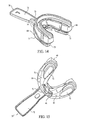
- FIG. 1 An oral appliance 1 according to one embodiment is shown in FIG. 1 .
- the oral appliance 1 includes an upper tray 10 adaptable to conform to a user's maxillary dentition and a lower tray 40 adaptable to conform to the user's mandibular dentition.
- a lower tray 40 may also be structured to provide, in combination with upper tray 10, a fixed amount of vertical spacing between the user's maxillary dentition and mandibular dentition. Accordingly, a user and/or dental specialist may select the proper lower tray 40 to provide a desired amount of mandibular advancement and/or a desired amount of vertical spacing.
- FIGS. 2 - 5 are front, bottom, top, and side plan views of upper tray 10 for oral appliance 1 of FIG. 1 .
- Upper tray 10 is generally U-shaped (e.g., having two legs 16b, 16c extending from a vertex 16a).
- Upper tray 10 includes an upper support member 11 and an upper moldable material 24.
- FIG. 6 A top plan view of upper support member 11 without upper moldable material 24 coupled thereto, for one embodiment, is illustrated in FIG. 6 .
- Upper support member 11 has a base 12 with a bonding surface 13 and an occlusal surface 14, an outer wall 15 with a front surface 16 and a rear surface 17, and an inner wall 18 with a front surface 19 and a rear surface 20.
- a single slotted engagement member 22 ( FIG. 3 ) extends from occlusal surface 14.
- a ramp 30 slopes downwardly from the top of a portion of inner wall 18 to a shelf 31 on bonding surface 13.
- ramp 30 is structured to assist with centering the user's dentition relative to tray 10 during fitting while shelf 31 is structured to help provide the desired vertical spacing between the patient's maxillary and mandibular dentition.
- Upper support member 11 may include identification markings 62.
- upper support member 11 includes the letter "U" on occlusal surface 14 ( FIG. 3 ).
- bonding surface 13 generally lies on a single plane (i.e., bonding surface 13 is generally flat). In an alternative embodiment, however, it is contemplated that bonding surface 13 may be somewhat curved in order to better accommodate the Curve of Spee associated with a user's dentition. Specifically, it is contemplated that bonding surface 13 is somewhat concave to accommodate the convex Curve of Spee associated with a user's maxillary dentition.
- upper support member 11 has a first width (A) at vertex 16a that is between approximately 0.30 inches (7.62 millimeters) and approximately 0.53 inches (13.46 millimeters).
- Upper support member 11 also has, relative to at least one of first leg 16b and second leg 16c, a second width (B) that is between approximately 0.50 inches (12.70 millimeters) and approximately 0.73 inches (18.54 millimeters).
- the distance between the outer portion of first leg 16b and the outer portion of second leg 16c is a third width (C) that is between approximately 2.0 inches (50.8 millimeters) and approximately 2.80 inches (71.12 millimeters).
- first width (A) is approximately 0.41 inches (10.41 millimeters)
- second width (B) is approximately 0.60 inches (15.24 millimeters)
- third width (C) is approximately 2.27 inches (57.66 millimeters).
- Upper support member 11 is sized such that the ratio between first width (A) and second width (B) is between approximately 0.60 and approximately 0.73 and the ratio between first width (A) and third width (C) is between approximately 0.17 and approximately 0.19.
- the ratio between first width (A) and second width (B) is approximately 0.68 and the ratio between first width (A) and third width (C) is approximately 0.18.
- upper support member 11 has, relative to vertex 16a, a first height (D) that is between approximately 0.30 inches (7.62 millimeters) and approximately 0.50 inches (12.70 millimeters), and has a second height (E) relative to at least one of a first leg 16b and a second leg 16c that is between approximately 0.025 inches (0.635 millimeters) and approximately 0.42 inches (10.67 millimeters).
- first height (D) and second height (E) are selected such that the ratio between second height (E) and first height (D) is between approximately 0.083 and approximately 0.125.
- upper support member 11 has a maximum height (F) that is approximately between 0.30 inches (7.62 millimeters) and 0.48 inches (12.19 millimeters).
- first height (D) is approximately 0.31 inches (7.87 millimeters)
- second height (E) is approximately 0.032 inches (0.813 millimeters)
- the ratio between second height (E) and first height (D) is approximately 0.10
- maximum height (F) is approximately 0.37 inches (9.40 millimeters).
- Upper support member 11 may be constructed of any rigid or semi-rigid material suitable for dental use.
- upper support member 11 has a density that is approximately between 0.040 lb/in3 and 0.050 lb/in 3 , a volume that is between approximately 0.12 in 3 and 0.22 in 3 and a weight that is between approximately 0.0071 lbs and 0.0081 lbs.
- upper support member 11 is constructed of a polycarbonate resin thermoplastic, such as LEXAN, and has a density of approximately 0.045 lb/in 3 , a volume of approximately 0.17 in 3 , and a weight of approximately 0.0076 lbs.
- upper support member 11 defines an upper region 21.
- Upper region 21 is generally defined, for example and without limitation, by base bonding surface 13, outer wall rear surface 17, and inner wall front surface 19.
- Upper region 21 is adapted to carry a portion of upper moldable material 24 therein.
- Upper moldable material 24 may be coupled to upper support member 11 in any suitable manner, for example and without limitation, using an adhesive.
- Upper moldable material 24 is not restricted within upper region 21. As seen for example in FIGS. 2 , 3 , and 5 , at least a portion of moldable material 24 extends out of upper region 21. In the current embodiment, it is contemplated that a portion of upper moldable material 24 extends at least 0.00984 inches (0.25 millimeters) above outer wall rear surface 17, at least 0.0256 inches (0.65 millimeters) above inner wall front surface 19, and at least 0.00394 inches (0.1 millimeters) from the end of bonding surface 13 of base 12 (i.e., from the end of the legs 16b, 16c of upper support member 11). It should be noted that the amount that moldable material 24 extends out of any portion of upper region 21 may be varied while remaining within the scope of the present invention.
- a moldable material may be selected which yields when heated, thereby conforming to the user's dentition during fitting, and re-hardens when cooled, thereby retaining the shape of the user's dentition imparted during fitting.
- a moldable material is sometimes referred to as a "boil and bite" material.
- moldable material 24 is an ethylene-vinyl acetate copolymer resin, such as ELVAX, having a density of approximately 0.035 lb/in 3 , a volume of approximately 0.75 in 3 , and a weight of approximately 0.0263 lbs.
- Oral appliance 1 incorporating an upper tray 10 provides benefits over other oral appliances which have an upper tray comprised solely of a moldable material or comprised of a moldable material which is substantially completely contained within a support member.
- upper support member 11 is smaller than other upper support members which completely enclose their moldable material.
- upper tray 10 is better able to conform to the user's maxillary dentition during the fitting process. More specifically, moldable material 24 is afforded a greater range of flow allowing moldable material 24 to conform to the user's dentition even if the user's dentition includes one or more misaligned teeth.
- Moldable material 24, such as that extending from the end of bonding surface 13, can be manipulated during the fitting process to conform to the user's dentition. Additionally, unlike other oral appliances which are comprised solely of a moldable material, upper support member 11 provides additional support to moldable material 24 during and after the fitting process. For these and other reasons, upper support member 11 provides increased patient comfort and allows upper tray 10 to fit a greater range of dental arch sizes.
- upper moldable material 24 has a channel 25 structured to center a user's dentition therein. More specifically, channel 25 includes a substantially V-shaped portion 26 structured to engage an anterior portion of the user's maxillary dentition (e.g., the upper centrals, laterals, and cuspids) and a substantially U-shaped portion 27 structured to engage a posterior portion of the user's maxillary dentition (e.g., the upper bicuspids and molars).
- the user or dental profession can better achieve the desired amount of mandibular advancement when upper tray 10 is engaged with a selected lower tray 40.
- V-shaped portion 26 and U-shaped portion 27 promote increased contact between the user's dentition and upper moldable material 24. Accordingly, an improved impression of the user's dentition is obtained during the fitting process.
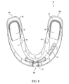
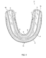
- FIGS. 7 - 10 are front, bottom, top, and side plan views, respectively, of lower tray 40 for oral appliance 1 of FIG. 1 .
- Lower tray 40 is generally U-shaped (e.g., with two legs 46b, 46c extending from a vertex 46a).
- Lower tray 40 includes a lower support member 41 and a lower moldable material 54.
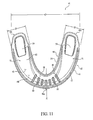
- FIG. 11 A top plan view of lower support member 41 without lower moldable material 54 coupled thereto, for one embodiment, is illustrated in FIG. 11 .
- Lower support member 41 has a base 42 with a bonding surface 43 and an occlusal surface 44, an outer wall 45 with a front surface 46 and a rear surface 47, and an inner wall 48 with a front surface 49 and a rear surface 50.
- An elongated engagement member 52 ( FIG. 10 ) extends from occlusal surface 44.
- a ramp 58 slopes downwardly from the top of a portion of inner wall 48 to a number of ribs 60 on bonding surface 43.
- ramp 58 is structured to assist with centering the user's dentition relative to tray 40 during fitting while ribs 60 are structured to help provide the desired vertical spacing between the patient's maxillary and mandibular dentition.
- Lower support member 41 may include identification markings 62.
- lower support member 41 includes the letter “L” and the numeral "000” on occlusal surface 14 ( FIG. 8 ).
- bonding surface 43 generally lies on a single plane (i.e., bonding surface 43 is generally flat). In an alternative embodiment, however, it is contemplated that bonding surface 43 may be somewhat curved in order to better accommodate the Curve of Spee associated with a user's dentition. Specifically, it is contemplated that bonding surface 43 is somewhat convex to accommodate the concave Curve of Spee associated with a user's mandibular dentition.
- legs 46b, 46c of lower support member 41 also include a number of bite pads 59 which are structured to help provide the desired vertical spacing (e.g., 10 millimeters of vertical spacing).
- Bite pads 59 may be sized to promote the proper bite angle during fitting such that of the user's bite pressure is distributed across the entire occlusal surface 44 of base 42 during the fitting process.
- bite pads 59 are similarly sized, however, different sized bite pads 59 are within the scope of the present invention
- lower support member 41 has a first width (A') at vertex 46a that is between approximately 0.30 inches (7.62 millimeters) and approximately 0.53 inches (13.46 millimeters).
- Lower support member 41 also has, relative to at least one of first leg 46b and second leg 46c, a second width (B') that is between approximately 0.50 inches (12.70 millimeters) and approximately 0.73 inches (18.54 millimeters).
- the distance between the outer portion of first leg 46b and the outer portion of second leg 46c is a third width (C') that is between approximately 2.0 inches (50.8 millimeters) and approximately 2.80 inches (71.12 millimeters).
- first width (A') is approximately 0.41 inches (10.41 millimeters)
- second width (B') is approximately 0.60 inches (15.24 millimeters)
- third width (C') is approximately 2.27 inches (57.66 millimeters).
- lower support member 41 is sized such that the ratio between first width (A') and second width (B') is between approximately 0.60 and approximately 0.73 and the ratio between first width (A') and third width (C') is between approximately 0.17 and 0.19.
- the ratio between first width (A') and second width (B') is approximately 0.68 and the ratio between first width (A') and third width (C') is approximately 0.18.
- lower support member 41 has, relative to vertex 46a, a first height (D') that is between approximately 0.30 inches (7.62 millimeters) and 0.5 inches (12.70 millimeters), and has a second height (E') relative to at least one of a first leg 46b and a second leg 46c that is between approximately 0.025 inches (0.635 millimeters) and approximately 0.42 inches (10.67 millimeters).
- first height (D') and second height (E') are selected such that the ratio between first height (D') and second height (E') is between approximately 0.083 and approximately 0.125.
- lower support member 41 has a maximum height (F') that is between approximately 0.30 inches (7.62 millimeters) and 0.48 inches (12.19 millimeters).
- first height (D') is approximately 0.32 inches (8.13 millimeters)
- second height (E') is approximately 0.032 inches (0.813 millimeters)
- the ratio between second height (E') and first height (D') is approximately 0.1
- maximum height (F') is approximately 0.42 inches (10.67 millimeters).
- Lower support member 41 may be constructed of any suitable rigid or semi-rigid material.
- lower support member 41 has a density that is approximately between 0.040 lb/in3 and 0.050 lb/in 3 , a volume that is between approximately 0.12 in 3 and 0.22 in 3 and a weight that is between approximately 0.0071 lbs and 0.0081 lbs.
- lower support member 41 is constructed of a polycarbonate resin thermoplastic, such as LEXAN, having a density of approximately 0.045 lb/in 3 , a volume of approximately 0.18 in 3 , and a weight of approximately 0.0081 lbs.
- upper tray 10 includes a ramp 30 (see FIG. 6 ) that slopes downwardly from the top of a portion of inner wall 18 to a shelf 31 located on the bonding surface 13 of base 12 and lower tray 40 includes a ramp 58 (see FIG. 11 ) that slopes downwardly from the top of a portion of inner wall 48 to a number of ribs 60 located on the bonding surface 43 of base 42.
- Ramp 30 is structured to assist in centering the user's maxillary dentition relative to upper tray 10
- ramp 58 is structured to assist in centering the user's mandibular dentition relative to lower tray 40 during fitting.
- Shelf 31 and ribs 60 are structured to help provide the desired vertical spacing between the user maxillary and mandibular dentition.
- lower support member 41 defines a lower region 51.
- Lower region 51 is generally defined, for example and without limitation, by base bonding surface 43, outer wall rear surface 47, and inner wall front surface 49.
- Lower region 51 is adapted to carry a portion of lower moldable material 54 therein.
- Lower moldable material 54 may be coupled to lower support member 41 in any suitable manner, for example and without limitation, using an adhesive.
- Lower moldable material 54 is not restricted within lower region 51. As seen for example in FIGS. 7 , 8 , and 10 , at least a portion of moldable material 54 extends out of lower region 51. In the current embodiment, it is contemplated that a portion of lower moldable material 54 extends at least 0.00984 inches (0.25 millimeters) above outer wall rear surface 47, at least 0.0256 inches (0.65 millimeters) above inner wall front surface 49, and at least 0.00394 inches (0.1 millimeters) from the end of bonding surface 43 of base 42 (i.e., from the end of the legs 46b, 46c of lower support member 41). It should be noted that the amount that moldable material 54 extends out of any portion of lower region 51 may be varied while remaining within the scope of the present invention.
- lower moldable material 54 may be selected which yields when heated, thereby conforming to the user's dentition during fitting, and re-hardens when cooled, thereby retaining the shape of the user's dentition imparted during fitting (i.e., a "boil and bite" material).
- lower moldable material 54 is an ethylene-vinyl acetate copolymer resin, such as ELVAX, having a density of approximately 0.035 lb/in 3 , a volume of approximately 0.66 in 3 , and a weight of approximately 0.0231 lbs.
- Oral appliance 1 incorporating a lower tray 40 provides the same benefits over other oral appliances which have a lower tray comprised solely of a moldable material or comprised of a moldable material which is substantially completely contained within a support member as were discussed above in conjunction with upper tray 10. Accordingly, for these and other reasons, lower support member 41 provides increased patient comfort and allows lower tray 40 to fit a greater range of dental arch sizes.
- lower moldable material 54 has a channel 55 structured to center a user's dentition therein. More specifically, channel 55 includes a substantially V-shaped portion 56 structured to engage an anterior portion of the user's mandibular dentition (e.g., the lower centrals, laterals, and cuspids) and a substantially U-shaped portion 57 structured to engage a posterior portion of the user's mandibular dentition (e.g., the lower bicuspids and molars).
- the user or dental profession can better achieve the desired amount of mandibular advancement when the selected lower tray 40 is engaged with upper tray 10.
- V-shaped portion 56 and U-shaped portion 57 promote increased contact between the user's dentition and lower moldable material 54. Accordingly, an improved impression of the user's dentition is obtained as a result of the fitting process.
- upper moldable material 24 and lower moldable material 54 are comprised of a polycaprolactone polymer or other aliphatic polyester (for example and without limitation, TONE P-700, TONE P-767 or TONE P-787 polycaprolactone polymers manufactured by Union Carbide Corporation).
- U.S. Patent Numbers 6,247,926 and 5,807,100 incorporated herein by reference, provides examples of the use of such materials.
- upper moldable material 24 and/or lower moldable material 54 are comprised of a combination of ELVAX and a polycaprolactone polymer or other aliphatic polyester Both the ELVAX and the polycaprolactone yield when heated. Accordingly, these materials are better able to flow around the user's dentition during the fitting process thereby providing a custom fit.
- the ELVAX remains relatively flexible and promotes retention of the oral appliance 1 within the patient's mouth.
- the polycaprolactone becomes relatively rigid after cooling. Accordingly, the polycaprolactone provides additional support to the ELVAX; support that may be lacking when the ELVAX is used alone.
- U.S. Patent Number 5,051,476 incorporated herein by reference, provides one such example of the use of ELVAX and polycaprolactone.
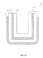
- FIGS. 20 - 21 show cross sectional views of upper trays 10', 10" according to embodiments in which the moldable material 24', 24" includes a combination of ELVAX 86 and polycaprolactone 85.
- ELVAX 86 and polycaprolactone 85 are arranged in alternating layers.
- moldable material 24' includes a layer of polycaprolactone 85 sandwiched between two layers of ELVAX 86.
- moldable material 24' is carried by support member 11', which in this instance, is constructed of polycarbonate.
- the present invention also contemplates eliminating one or more layers, for example and without limitation, eliminating the layer of ELVAX adjacent to support member 11'.
- polycaprolactone 85 is suspended within and throughout ELVAX 86.
- Moldable material 24" is carried by support member 11", which in this instance, is also constructed of polycarbonate.
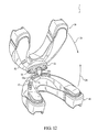
- FIG. 12 illustrates the engagement of upper tray 10 and lower tray 40.
- lower tray 40 is arranged approximately perpendicular to upper tray 10.
- a leading edge 52a of elongated engagement member 52 is brought into contact with a portion of slotted engagement member 22 such that end 52b is inserted into a bottom slot 33 of slotted engagement member 22.
- Lower tray 40 and upper tray 10 are then rotated, relative to each other, as indicated by directional arrows 34, such that end 52b enters front slot 32 (see FIG. 1 ) and is "hooked".
- end 52b is capable of moving a predetermined amount laterally (as indicated by directional arrow 35) and a predetermined amount vertically (as indicated by directional arrow 36) within slotted engagement member 22.
- end 52b can move between 10 - 13 millimeters laterally and between 0.8 - 1.2 millimeters vertically. It should be noted, however, that the amount of predetermined lateral and vertical movement may be altered while remaining within the scope of the present invention.
- slotted engagement member 22 may extend from lower support member 41 of lower tray 40 and the elongated support member 52 may extend from upper support member 11.
- the length of elongated engagement member 52, the size of hook end 52b, and the orientation of hook end 52b may be altered while remaining within the scope of the present invention.
- slotted engagement member 22 includes a frangible portion 23 (see FIG. 2 ) which is structured to break when approximately 36 lbs of force are applied thereto.
- Frangible portion 23 may be structured to break when a different amount of predetermined amount of force is applied thereto.
- the applied force at which frangible portion 23 breaks may vary depending upon the direction that the force is applied.
- elongated engagement member 52 may include a frangible portion (not shown).
- each of the multiple lower trays 40 is structured to impart a different fixed amount of mandibular advancement when engaged with upper tray 10.
- the amount of mandibular advancement imparted by each lower tray 40 is determined by the fixed placement of elongated engagement member 52 relative to, for example, vertex 46a of the outer wall front surface 46 at vertex 46a.
- leading edge 52a of elongated engagement member 52 is offset approximately 1.70 millimeters from the outer wall front surface at vertex 46a of the outer wall front surface 46.
- lower tray 40 is structured to provide a fixed amount of mandibular advancement which brings the user's lower central teeth into alignment with the user's upper central teeth in the current embodiment.
- Lower tray 40' illustrated in FIG. 13 is structured to provide a fixed amount of mandibular advancement such that the user's lower central teeth extend approximately 0.098 inches (2.5 millimeters) out from the user's upper central teeth (i.e., lower tray 40' imparts a Class III malocclusion or "underbite"). Specifically, leading edge 52a' of elongated engagement member 52' is offset approximately 4.20 millimeters relative to the outer wall front surface 46' at vertex 46a'.
- oral appliance 1 also includes an additional lower tray which provides fixed mandibular advancement such that the user's lower central teeth extend approximately 0.197 inches (5 millimeters) out from the user's upper central teeth.
- upper tray 10 and lower tray 40 are asymmetric, the amount of mandibular advancement may also be varied by flipping upper tray 10 and lower tray 40.
- oral appliance 1 imparts an amount of mandibular advancement to cause the user's upper central teeth to be aligned with the user's lower central teeth.
- oral appliance 1 imparts an amount of mandibular advancement to cause the user's lower central teeth to extend approximately 0.197 inches (5 millimeters) out from the user's central upper teeth (i.e., to cause a Class III malocclusion or "underbite"). Accordingly, a small number of lower trays may be needed to obtain a larger range of mandibular advancement.
- Oral appliance 1 may be part of an assembly/system which includes a number of holding trays which are structured to couple with the upper and lower trays.
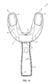
- FIGS. 14 and 15 illustrate a holding tray 70 engaged with lower tray 40 and
- FIG. 16 is a bottom plan view of holding tray 70 according to one embodiment.
- Holding tray 70 includes a generally U-shaped frame 71 which is sized to accept lower tray 40 therein.
- Frame 71 includes a base 78 with an outer wall 79 extending therefrom.
- base 78 includes a gate 77 which is structured to accommodate elongated engagement member 52.
- An ejector pin 76 is employed to maintain lower tray 40 in contact with holding tray 70.
- ejector pin 76 is located along the posterior side of gate 77. Accordingly, when lower tray 40 and holding tray 70 are coupled, ejector pin 76 engages inner wall 48 such that lower tray 40 "snaps-into" holding tray 70.
- holding tray 70 also includes a handle 72 which projects from a front surface 80 of outer wall 79 at vertex 73 of frame 71.
- Handle 70 may be employed by the user to suspend lower tray 40 within a heating medium during the fitting process.
- a user may grasp and hold handle 72 while moldable material 54 is submerged within the boiling water. Once moldable material 54 has yielded (e.g., has become soft enough to be reshaped or molded), the user may remove lower tray 40 from the boiling water and insert lower tray 40 into their mouth.
- Holding tray 70 promotes proper insertion of lower tray 40 into a user's mouth during the fitting process. Specifically, a user employing holding tray 70 has the additional leverage provided by handle 72 to better align lower tray 40 within their mouth.
- An occlusal surface 81 of base 78 may include a number of bite pads 75 located thereon.
- Bite pads 75 may be constructed of an elastomeric material that increases the user's comfort during the fitting process although other materials are contemplated. Additionally, bite pads 75 may be sized to promote the proper bite angle during fitting such that of the user's bite pressure is distributed across the entire occlusal surface 81 of base 78 during the fitting process. In the current embodiment, bite pads 75 are similarly sized, however, different sized bite pads 75 are within the scope of the present invention.
- holding tray 70 may have an ejector pin 76 located along the anterior side of gate 77 and an inner wall which engages outer wall 45 such that lower tray 40 "snaps-into" holding tray 70.
- ejector pin 76 located along the anterior side of gate 77 and an inner wall which engages outer wall 45 such that lower tray 40 "snaps-into" holding tray 70.
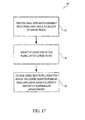
- FIG. 17 illustrates operational process 90 for effecting the patency of a user's airway according to one embodiment.
- Operational process begins at operation 91 which provides an oral appliance assembly including an oral appliance, such as oral appliance 1 shown in FIG. 1 , having an upper tray and plurality of lower trays.
- upper tray 10 is adaptable to conform to a user's maxillary dentition and each of the plurality of lower trays 40, 40' is adaptable to conform to the user's mandibular dentition.
- Upper tray 10 and lower tray(s) 40, 40' may be fitted to a user's maxillary dentition and mandibular dentition, respectively, using for example, operational process 100 and operational process 110 which will be described in more detail below.
- Each of at least some of lower trays 40, 40' is structured to couple with upper tray 10 to impart a different fixed amount of mandibular advancement.
- a lower tray may be selected based upon the particular amount of mandibular advancement that is desired.
- lower tray 40 is structured to provide a fixed amount of mandibular advancement to bring the user's lower central teeth into alignment with the user's upper central teeth
- lower tray 40' is structured to provide a fixed amount of mandibular advancement such that the user's lower central teeth extend approximately 2.5 millimeters out from the user's upper central teeth (i.e., lower tray 40' imparts a Class III malocclusion or "underbite").
- the selection of the proper lower tray may be made by a dental professional, a user, or others.
- Operational control is passed to operation 93 after one of the lower trays is selected.
- the upper tray is coupled with the selected lower tray to form an oral appliance having a desired amount of mandibular advancement.
- upper tray 10 includes a slotted engagement member 22 and lower trays 40, 40' include an elongated engagement member 52.
- Upper tray 10 and selected lower tray 40,40' may be coupled as described above in conjunction with FIG. 12 . After the upper and lower trays are coupled, oral appliance may be inserted into the user's mouth to effect the patency of a user's airway.
- FIG. 18 illustrates operational process 100 for fitting an oral appliance according to one embodiment.
- Operational process 100 begins with taking an imprint of a user's dentition at operation 101.
- An imprint is generally a negative likeness of the user's dentition.
- the imprint is taken by a dental professional using a plastic material which hardens or sets while in contact with the user's dentition.
- two imprints are taken: the first is an imprint of the user's maxillary dentition and the second is an imprint of the user's mandibular dentition.
- operation 102 a casting of the user's dentition is created.
- the casting may be made, for example, by filling the imprint with plaster of Paris or artificial stone.
- castings of both the user's maxillary and mandibular dentition are created. Once completed, the castings provide a facsimile of the user's maxillary and mandibular dentition.
- each casting created at operation 102 is placed in heating medium, for example and without limitation, water.
- the temperature of the heating medium is maintained between approximately 180° and 220° Fahrenheit (between approximately 82.22° and 104.4° Celsius).
- top tray 10 and a selected lower tray 40 are also placed in the heating medium such that moldable material 24 and moldable material 54 begin to yield (i.e., soften). It should be noted that the manner of heating and the value of the predetermined temperature may be altered while remaining within the scope of the present invention.
- the casting After reaching the predetermined temperature, the casting is pressed into the moldable material of an oral appliance.
- the heated casting of the user's maxillary dentition is placed within upper moldable material 24 of upper tray 10.
- the heat retained by this casting permits upper moldable material 24 to remain in a yielded state for a longer period of time, thereby allowing a more accurate impression of the user's maxillary dentition to be formed within upper moldable material 24.
- upper moldable material 24 has been fit to the user's maxillary dentition.
- the heated casting of the user's mandibular dentition is placed within lower moldable material 54 of lower tray 40.
- FIG. 19 illustrates operational process 110 for fitting an oral appliance according to another embodiment.
- Operational process 110 begins when an oral appliance tray is coupled with a holding tray at operation 111.
- the oral appliance tray is at least one of an upper tray 10 with moldable material 24 and a lower tray 40, 40' with moldable material 54, 54' and holding tray 70 has a handle 72 attached thereto.
- operational control is passed to operation 112 at which the oral appliance tray is submerged within a heating medium while at least a least a portion of the handle remains out of the heating medium.
- a user can grasp an end of handle 72 and submerge upper tray 10 within boiling water. The user may continue to hold handle 72 (which is not submerged in the boiling water) while upper tray 10 is submerged.
- Operational control is then passed to operation 113 at which the oral appliance tray is removed from the heating medium with the handle.
- a user can remove upper tray 10 from the boiling water (with handle 72) after upper moldable material 24 reaches a yielded state.
- Operational control is then passed to operation 114 at which the oral appliance tray is inserted into a user's mouth using the handle.
- a user can insert upper tray 10 into their mouth while maintaining a grip on handle 72.
- Handle 72 provides additional leverage to the user such that proper alignment of upper tray 72 within the user's mouth is facilitated. Additionally, handle 72 eliminates the need for the user to touch upper tray 10 which may still be somewhat hot from being submerged within the boiling water.
- operational control is passed to operation 115 at which an impression of at least a portion of the user's dentition is made.
- the user is able to bite into upper moldable material 24 which is in a yielded state.
- Upper moldable material 24 then flows around the user's dentition to form the impression.
- operational process 100 may provide more accurate results than operational process 110.
- a casting retains more heat than the moldable material. This heat is transferred from the casting to the moldable material, thus causing the moldable material to remain in the yielded state for an increase length of time as compared to heating the moldable material alone (e.g., operational process 110). Because the moldable material is in the yielded state for a longer length of time, the moldable material has a better opportunity to flow around the casting and form the impression. Furthermore, once placed in the moldable material, the casting remains substantially stationary; whereas a user biting directly into the moldable material (operational process 110) will move his/her jaw.
- Oral appliance 1 also may be adapted for use with a patient interface device.
- a patient receiving treatment for sleep apnea may be required to wear a nasal mask, oral mask, full-face mask, or other patient interface device.
- Examples of oral appliances used in combination with a patient interface device are found in U.S. Patent Nos. 2,521,084 ; 4,470,413 ; 5,573,994 ; 5,752,510 ; 5,954,048 ; 6,012,455 ; 6,405,729 ; 6,789,543 ; and 7,021,312 .
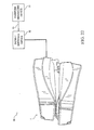
- FIG. 22 illustrates a system 90 for treating sleep apnea and/or other respiratory ailments.
- system 90 includes a pressure generating device 91, a nasal mask 92, a conduit 93, and oral appliance 1'.
- Oral appliance 1' is shown schematically coupled with nasal mask 92 which is operatively connected to pressure generating device 91 via conduit 93.
- Oral appliance 1' is structured to stabilize nasal mask 92 relative to the patient's face.
- Nasal mask 92 is structured to deliver, to the patient's airway, a flow of pressurized breathing gas produced by gas generating device 91.
- nasal appliance 92 By coupling with oral appliance 1', nasal appliance 92 is better secured to the patient's face and the patient's sleep apnea and/or other respiratory aliments are treated through both mandibular advancement and the application of positive airway pressure. It is contemplated that oral appliance 1' may be coupled with the patient interface device in any suitable manner.
- Oral appliance 1 may also be adapted to be used in combination with a patient monitoring device and/or intraoral electromuscular stimulation device.
- oral appliances with electrodes extending therefrom for use with a patient monitoring device and/or intraoral electromuscular stimulation device are found in U.S. Patent Nos. 6,618,627 and 5,190,053 .
- FIG. 23 illustrates oral appliance 1" with electrodes 95, 95' extending therefrom according to one embodiment.
- Electrodes 95, 95' may be structured, for example, to capture electromyography (EMG) activity produced by one or more of the patient's muscles (e.g., the masseter muscle). Measured EMG activity may be employed, for example and without limitation, to monitor bruxism and oral appliance wear compliance. EMG electrodes 95, 95' may be placed at any suitable location on oral appliance 1" such that, after fitting oral appliance 1", the EMG activity of the targeted muscle may be captured. As shown in FIG. 23 , for example, EMG electrodes 95 are placed in upper moldable material 24", and EMG electrodes 95' are placed on lower support member 41".
- a monitoring system (not shown) wirelessly communicates with EMG electrodes 95, 95'. The monitoring system may include a processor for analyzing the EMG activity detected in the masseter muscle.
- Electrodes 95, 95' may be structured, as another example, to provide intraoral electromuscular stimulation to reduce or minimize the occurrence of a breathing disorder, such as obstructive sleep apnea.
- Intraoral electromuscular stimulation may be employed, for instance, to provide electrical stimulation to the muscles of the upper airway responsible for maintaining the patency of the airway.
- electromuscular stimulation induces contraction in the muscles of the upper airway, thereby preventing or minimizing blockage of a user's airway.
- Electrodes 95, 95' may be altered while remaining within the scope of the present invention.
- only upper tray 10" may have electrodes 95 located thereon and/or electrodes 95, 95' may include a wire for communicating with the monitoring system.
- Electrodes 95, 95' may also be placed directly on the surface of upper moldable material 24, lower moldable material 54, or both. During the molding process the upper moldable material 24 or lower moldable material 54 is typically moved outward, i.e., toward the intraoral surfaces of the user's oral cavity as the teeth engage the moldable material.
- upper moldable material 24 and/or lower moldable material 54 serves to contact the electrode with the intraoral surfaces of the user's oral cavity so that no other electrode placement devices are needed.
- present invention also contemplates using electrode placement devices, such as springs and support members, to ensure that the electrodes 95, 95' are engaged with the intraoral surfaces of the user.
- patient monitoring devices e.g., vibration monitoring devices, sound monitoring devices, etc.
- components may be employed in conjunction with oral appliance 1".
Landscapes
- Health & Medical Sciences (AREA)
- Engineering & Computer Science (AREA)
- Biomedical Technology (AREA)
- Heart & Thoracic Surgery (AREA)
- Otolaryngology (AREA)
- Pulmonology (AREA)
- Nursing (AREA)
- Orthopedic Medicine & Surgery (AREA)
- Veterinary Medicine (AREA)
- Public Health (AREA)
- Vascular Medicine (AREA)
- Life Sciences & Earth Sciences (AREA)
- Animal Behavior & Ethology (AREA)
- General Health & Medical Sciences (AREA)
- Mechanical Engineering (AREA)
- Manufacturing & Machinery (AREA)
- Orthopedics, Nursing, And Contraception (AREA)
Description
- The present invention pertains to an oral appliance and more particularly to an oral appliance for the treatment of snoring and sleep apnea.
- Individuals suffering from sleep-related breathing disorders, such as excessive snoring and sleep apnea, have an increased risk of experiencing severe health problems. Studies have shown, for instance, that individuals suffering from obstructive sleep apnea (OSA) are more likely to have a stroke, heart failure, hypertension, and depression, among others. OSA is characterized by repetitive collapse of the upper airway during sleep. This yields episodes of reduced airflow, hypoxemia (reduced oxygen level in the blood), hypercapnia (elevated circulating carbon dioxide, CO2), and arousal from sleep to reestablish a stable airway.
- Severe sleep-related breathing disorders may require positive airway pressure (PAP) therapy. Less severe sleep-related breathing disorders, however, may be treated with other therapies or devices, such as an oral appliance. Generally, an oral appliance includes upper and lower dental trays coupled together in such a way as to impart forward advancement of the user's mandible (i.e., lower jaw) relative to the user's maxilla (upper jaw). Accordingly, an oral appliance may also be referred to as a "mandibular advancement device" or "MAD". Forward advancement of the mandible helps prevent the soft tissue of the tongue and the throat from collapsing into, and thus blocking, the user's airway during sleep.
- Achieving the correct amount of forward mandibular advancement with an oral appliance is important. A user, for example, may continue to suffer from a sleep-related breathing disorder if the forward mandibular advancement imparted by the oral appliance is inadequate (e.g., the soft tissue of the user's tongue and throat are not prevented from collapsing into the user's airway). On the other hand, if the forward mandibular advancement imparted by the oral appliance is excessive, the user may experience unnecessary discomfort. The discomfort may cause undesirable arousal from sleep and/or cause the user to stop wearing the oral appliance all together.
- Some oral appliances, such as those described in
U.S. Patent Nos. 5,829,441 ,5,365,945 , and5,868,138 , include mechanisms for adjusting the amount of mandibular advancement provided by the oral appliance. These and similar oral appliances, however, are expensive, complicated to manufacture, and have adjustment mechanisms are difficult to operate. Additionally, oral appliances incorporating adjustment mechanisms tend to be bulky, thereby adversely impacting the user's comfort level. Furthermore, known oral appliances are difficult to properly fit, do not allow sufficient vertical or horizontal movement of the jaw when worn, and are not flexible enough to allow a "one size fits all" application (e.g., the oral appliance may not be appropriate for both a user having a relatively small dental arch and a user having a relatively large dental arch). - Accordingly, a need exists for an improved oral appliance for the treatment of snoring and sleep apnea which overcomes these and other problems associated with known oral appliances.
-
US 6,516,805 discloses a dental device having a post to extend the user's lower jaw forward to reduce snoring in which the length of the post is variable to adjust the gap between the upper and lower jaw and provides variation in the forward position of the post. -
US 2003/217753 discloses a device which when fitted in the user's mouth pulls the lower jaw forward to facilitate improved breathing. - In accordance with an aspect of the present invention, an oral appliance system comprises an upper tray and a plurality of lower trays. The upper tray is adaptable to conform to a user's maxillary dentition and each of the lower trays is adaptable to conform to the user's mandibular dentition. Each of the lower trays comprise astructure for coupling with the upper tray and to impart a different fixed amount of mandibular advancement.
- The oral appliance tray may comprise a moldable material and a support member. The support member may have a base, an outer wall, and an inner wall, which define a region adapted to couple with the moldable material. A portion of the moldable material may extend out of the region.
- The oral appliance tray may comprise a moldable material and a support member structured to carry a portion of the moldable material. The support member may have a ramp adapted to promote alignment of a user's dentition relative to the moldable material.
- The oral appliance assembly may comprise an oral appliance tray adaptable to conform to a user's dentition and a holding tray adapted to promote proper insertion of the oral appliance tray into a user's mouth. The holding tray may comprise a generally U-shaped frame structured to couple with the oral appliance tray and a handle located substantially at the vertex of the holding tray frame.
- According to another aspect of the present invention, a method of operating an oral appliance system comprises providing an oral appliance assembly comprising an upper tray adaptable to conform to a user's maxillary dentition and a plurality of lower trays each adaptable to conform to the user's mandibular dentition, wherein each of the lower trays comprises structure for a coupling with the upper tray to impart a different fixed amount of mandibular advancement, enabling a selection of at least one of the plurality of lower trays, and enabling coupling of the upper tray with a selected one of the lower trays to form an oral appliance having a desired amount of mandibular advancement.
- The oral appliance tray may comprise a generally U-shaped support member having a first width relative to a vertex thereof that is between approximately 0.30 inches (7.62 millimeters) and approximately 0.53 inches (13.46 millimeters) and having a second width relative to at least one of a first leg and a second leg thereof that is between approximately 0.50 inches (12.7 millimeters) and approximately 0.73 inches (18.54 millimeters).
- A holding tray adapted to promote proper insertion of an oral appliance into a user's mouth comprises a generally U-shaped frame and a handle may be included. The frame may be structured to engage the oral appliance and may have a base with an outer wall extending therefrom. The handle. projecting from a front surface of the outer wall, may be substantially located at the vertex of the U-shaped frame.
- These and other objects, features, and characteristics of the present invention, as well as the methods of operation and functions of the related elements of structure and the combination of parts and economies of manufacture, will become more apparent upon consideration of the following description and the appended claims with reference to the accompanying drawings, all of which form a part of this specification, wherein like reference numerals designate corresponding parts in the various figures. It is to be expressly understood, however, that the drawings are for the purpose of illustration and description only and are not intended as a definition of the limits of the invention.
-
-
FIG. 1 is a perspective view of an oral appliance according to one embodiment. -
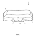
FIG. 2 is a front plan view of the upper tray for the oral appliance illustrated inFIG. 1 . -
FIG. 3 is a bottom plan view of the upper tray illustrated inFIG. 2 . -
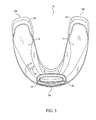
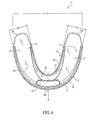
FIG. 4 is a top plan view of the upper tray illustrated inFIG. 2 . -
FIG. 5 is a side plan view of the upper tray illustrated inFIG. 2 . -
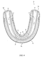
FIG. 6 is a top plan view of the upper support member portion of the upper tray illustrated inFIG. 2 . -
FIG. 7 is a front plan view of the lower tray for the oral appliance illustrated inFIG. 1 . -
FIG. 8 is a bottom plan view of the lower tray illustrated inFIG. 7 . -
FIG. 9 is a top plan view of the lower tray illustrated inFIG. 7 . -
FIG. 10 is a side plan view of the lower tray illustrated inFIG. 7 . -
FIG. 11 is a top plan view of the lower support member portion of the lower tray illustrated inFIG. 7 . -
FIG. 12 illustrates the engagement of the upper and lower trays according to one embodiment. -
FIG. 13 is a side plan view of a lower tray for the oral appliance illustrated inFIG. 1 according to another embodiment. -
FIG. 14 is top perspective view of a holding tray engaged with a lower tray according to one embodiment. -
FIG. 15 is bottom perspective view of the holding tray and lower tray ofFIG. 14 . -
FIG. 16 is a bottom plan view of the holding tray illustrated inFIG. 14 according to one embodiment. -
FIG. 17 illustrates an operational process for effecting the patency of a user's airway according to one embodiment. -
FIG. 18 illustrates an operational process for fitting an oral appliance according to one embodiment. -
FIG. 19 illustrates operational process for fitting an oral appliance according to another embodiment. -
FIG. 20 illustrates a layered moldable material according to one embodiment. -
FIG. 21 illustrates an embedded molded material according to one embodiment. -
FIG. 22 illustrates the oral appliance ofFIG. 1 schematically coupled with a patient interface device. -
FIG. 23 illustrates the oral appliance ofFIG. 1 with electromyography electrodes according to one embodiment. - As employed herein, the term "mandibular advancement" and derivatives thereof refer to the anterior movement of a user's mandible (lower jaw) relative to the user's maxilla (upper jaw). Lateral movement, as employed herein, refers to the left/right movement of the mandible relative to a sagittal plane passing through the interproximal space of the maxillary centrals. Vertical movement, as employed herein, refers to an increase/decrease of the spacing between the occlusal surfaces of the mandibular dentition and the occlusal surfaces of the maxillary dentition.
- An
oral appliance 1 according to one embodiment is shown inFIG. 1 . Theoral appliance 1 includes anupper tray 10 adaptable to conform to a user's maxillary dentition and alower tray 40 adaptable to conform to the user's mandibular dentition. Although only onelower tray 40 is illustrated inFIG. 1 , it is contemplated that multiplelower trays 40 will be provided. As will be discussed in more detail below, each of at least some of the multiplelower trays 40 is structured to impart a different fixed amount of mandibular advancement when engaged withupper tray 10. Alower tray 40 may also be structured to provide, in combination withupper tray 10, a fixed amount of vertical spacing between the user's maxillary dentition and mandibular dentition. Accordingly, a user and/or dental specialist may select the properlower tray 40 to provide a desired amount of mandibular advancement and/or a desired amount of vertical spacing. -
FIGS. 2 - 5 are front, bottom, top, and side plan views ofupper tray 10 fororal appliance 1 ofFIG. 1 .Upper tray 10 is generally U-shaped (e.g., having twolegs vertex 16a).Upper tray 10 includes anupper support member 11 and an uppermoldable material 24. - A top plan view of
upper support member 11 without uppermoldable material 24 coupled thereto, for one embodiment, is illustrated inFIG. 6 .Upper support member 11 has a base 12 with abonding surface 13 and anocclusal surface 14, anouter wall 15 with afront surface 16 and arear surface 17, and aninner wall 18 with afront surface 19 and arear surface 20. A single slotted engagement member 22 (FIG. 3 ) extends fromocclusal surface 14. Aramp 30 slopes downwardly from the top of a portion ofinner wall 18 to ashelf 31 onbonding surface 13. As will be discussed in greater detail below,ramp 30 is structured to assist with centering the user's dentition relative totray 10 during fitting whileshelf 31 is structured to help provide the desired vertical spacing between the patient's maxillary and mandibular dentition.Upper support member 11 may includeidentification markings 62. In the current embodiment, for example and without limitation,upper support member 11 includes the letter "U" on occlusal surface 14 (FIG. 3 ). - Traveling from
leg 16b toleg 16c alongbase 12,bonding surface 13 generally lies on a single plane (i.e., bondingsurface 13 is generally flat). In an alternative embodiment, however, it is contemplated that bondingsurface 13 may be somewhat curved in order to better accommodate the Curve of Spee associated with a user's dentition. Specifically, it is contemplated that bondingsurface 13 is somewhat concave to accommodate the convex Curve of Spee associated with a user's maxillary dentition. - Generally,
upper support member 11 has a first width (A) atvertex 16a that is between approximately 0.30 inches (7.62 millimeters) and approximately 0.53 inches (13.46 millimeters).Upper support member 11 also has, relative to at least one offirst leg 16b andsecond leg 16c, a second width (B) that is between approximately 0.50 inches (12.70 millimeters) and approximately 0.73 inches (18.54 millimeters). The distance between the outer portion offirst leg 16b and the outer portion ofsecond leg 16c is a third width (C) that is between approximately 2.0 inches (50.8 millimeters) and approximately 2.80 inches (71.12 millimeters). In the current embodiment, first width (A) is approximately 0.41 inches (10.41 millimeters), second width (B) is approximately 0.60 inches (15.24 millimeters), and third width (C) is approximately 2.27 inches (57.66 millimeters). -
Upper support member 11 is sized such that the ratio between first width (A) and second width (B) is between approximately 0.60 and approximately 0.73 and the ratio between first width (A) and third width (C) is between approximately 0.17 and approximately 0.19. In the current embodiment, for example, the ratio between first width (A) and second width (B) is approximately 0.68 and the ratio between first width (A) and third width (C) is approximately 0.18. - Referring briefly to
FIG. 5 ,upper support member 11 has, relative tovertex 16a, a first height (D) that is between approximately 0.30 inches (7.62 millimeters) and approximately 0.50 inches (12.70 millimeters), and has a second height (E) relative to at least one of afirst leg 16b and asecond leg 16c that is between approximately 0.025 inches (0.635 millimeters) and approximately 0.42 inches (10.67 millimeters). In the current embodiment, first height (D) and second height (E) are selected such that the ratio between second height (E) and first height (D) is between approximately 0.083 and approximately 0.125. Furthermore,upper support member 11 has a maximum height (F) that is approximately between 0.30 inches (7.62 millimeters) and 0.48 inches (12.19 millimeters). - In the current embodiment, first height (D) is approximately 0.31 inches (7.87 millimeters), second height (E) is approximately 0.032 inches (0.813 millimeters), the ratio between second height (E) and first height (D) is approximately 0.10, and maximum height (F) is approximately 0.37 inches (9.40 millimeters).
-
Upper support member 11 may be constructed of any rigid or semi-rigid material suitable for dental use. In the current embodiment,upper support member 11 has a density that is approximately between 0.040 lb/in3 and 0.050 lb/in3, a volume that is between approximately 0.12 in3 and 0.22 in3 and a weight that is between approximately 0.0071 lbs and 0.0081 lbs. For example,upper support member 11 is constructed of a polycarbonate resin thermoplastic, such as LEXAN, and has a density of approximately 0.045 lb/in3, a volume of approximately 0.17 in3, and a weight of approximately 0.0076 lbs. - Returning to
FIG. 6 ,upper support member 11 defines anupper region 21.Upper region 21 is generally defined, for example and without limitation, bybase bonding surface 13, outer wallrear surface 17, and inner wallfront surface 19.Upper region 21 is adapted to carry a portion of uppermoldable material 24 therein. Uppermoldable material 24 may be coupled toupper support member 11 in any suitable manner, for example and without limitation, using an adhesive. - Upper
moldable material 24 is not restricted withinupper region 21. As seen for example inFIGS. 2 ,3 , and5 , at least a portion ofmoldable material 24 extends out ofupper region 21. In the current embodiment, it is contemplated that a portion of uppermoldable material 24 extends at least 0.00984 inches (0.25 millimeters) above outer wallrear surface 17, at least 0.0256 inches (0.65 millimeters) above inner wallfront surface 19, and at least 0.00394 inches (0.1 millimeters) from the end ofbonding surface 13 of base 12 (i.e., from the end of thelegs moldable material 24 extends out of any portion ofupper region 21 may be varied while remaining within the scope of the present invention. - A moldable material may be selected which yields when heated, thereby conforming to the user's dentition during fitting, and re-hardens when cooled, thereby retaining the shape of the user's dentition imparted during fitting. Such a moldable material is sometimes referred to as a "boil and bite" material. In the current embodiment, for example,
moldable material 24 is an ethylene-vinyl acetate copolymer resin, such as ELVAX, having a density of approximately 0.035 lb/in3, a volume of approximately 0.75 in3, and a weight of approximately 0.0263 lbs. -
Oral appliance 1 incorporating anupper tray 10 provides benefits over other oral appliances which have an upper tray comprised solely of a moldable material or comprised of a moldable material which is substantially completely contained within a support member. For example,upper support member 11 is smaller than other upper support members which completely enclose their moldable material. Furthermore, by allowing a portion of uppermoldable material 24 to extend out fromupper support member 11,upper tray 10 is better able to conform to the user's maxillary dentition during the fitting process. More specifically,moldable material 24 is afforded a greater range of flow allowingmoldable material 24 to conform to the user's dentition even if the user's dentition includes one or more misaligned teeth.Moldable material 24, such as that extending from the end ofbonding surface 13, can be manipulated during the fitting process to conform to the user's dentition. Additionally, unlike other oral appliances which are comprised solely of a moldable material,upper support member 11 provides additional support tomoldable material 24 during and after the fitting process. For these and other reasons,upper support member 11 provides increased patient comfort and allowsupper tray 10 to fit a greater range of dental arch sizes. - Referring now to
FIG. 4 , uppermoldable material 24 has achannel 25 structured to center a user's dentition therein. More specifically,channel 25 includes a substantially V-shapedportion 26 structured to engage an anterior portion of the user's maxillary dentition (e.g., the upper centrals, laterals, and cuspids) and a substantiallyU-shaped portion 27 structured to engage a posterior portion of the user's maxillary dentition (e.g., the upper bicuspids and molars). By centering the user's upper dentition within uppermoldable material 24, the user or dental profession can better achieve the desired amount of mandibular advancement whenupper tray 10 is engaged with a selectedlower tray 40. In addition to centering the user's teeth withinchannel 25, V-shapedportion 26 andU-shaped portion 27 promote increased contact between the user's dentition and uppermoldable material 24. Accordingly, an improved impression of the user's dentition is obtained during the fitting process. -
FIGS. 7 - 10 are front, bottom, top, and side plan views, respectively, oflower tray 40 fororal appliance 1 ofFIG. 1 .Lower tray 40 is generally U-shaped (e.g., with twolegs vertex 46a).Lower tray 40 includes alower support member 41 and a lowermoldable material 54. - A top plan view of
lower support member 41 without lowermoldable material 54 coupled thereto, for one embodiment, is illustrated inFIG. 11 .Lower support member 41 has a base 42 with abonding surface 43 and anocclusal surface 44, anouter wall 45 with afront surface 46 and arear surface 47, and aninner wall 48 with afront surface 49 and arear surface 50. An elongated engagement member 52 (FIG. 10 ) extends fromocclusal surface 44. Aramp 58 slopes downwardly from the top of a portion ofinner wall 48 to a number ofribs 60 onbonding surface 43. As will be discussed in greater detail below,ramp 58 is structured to assist with centering the user's dentition relative totray 40 during fitting whileribs 60 are structured to help provide the desired vertical spacing between the patient's maxillary and mandibular dentition.Lower support member 41 may includeidentification markings 62. In the current embodiment, for example and without limitation,lower support member 41 includes the letter "L" and the numeral "000" on occlusal surface 14 (FIG. 8 ). - Traveling from
leg 46b toleg 46c alongbase 42,bonding surface 43 generally lies on a single plane (i.e., bondingsurface 43 is generally flat). In an alternative embodiment, however, it is contemplated that bondingsurface 43 may be somewhat curved in order to better accommodate the Curve of Spee associated with a user's dentition. Specifically, it is contemplated that bondingsurface 43 is somewhat convex to accommodate the concave Curve of Spee associated with a user's mandibular dentition. - In the current embodiment,
legs lower support member 41 also include a number ofbite pads 59 which are structured to help provide the desired vertical spacing (e.g., 10 millimeters of vertical spacing).Bite pads 59 may be sized to promote the proper bite angle during fitting such that of the user's bite pressure is distributed across the entireocclusal surface 44 ofbase 42 during the fitting process. In the current embodiment,bite pads 59 are similarly sized, however, differentsized bite pads 59 are within the scope of the present invention - Generally,
lower support member 41 has a first width (A') atvertex 46a that is between approximately 0.30 inches (7.62 millimeters) and approximately 0.53 inches (13.46 millimeters).Lower support member 41 also has, relative to at least one offirst leg 46b andsecond leg 46c, a second width (B') that is between approximately 0.50 inches (12.70 millimeters) and approximately 0.73 inches (18.54 millimeters). The distance between the outer portion offirst leg 46b and the outer portion ofsecond leg 46c is a third width (C') that is between approximately 2.0 inches (50.8 millimeters) and approximately 2.80 inches (71.12 millimeters). In the current embodiment, first width (A') is approximately 0.41 inches (10.41 millimeters), second width (B') is approximately 0.60 inches (15.24 millimeters), and third width (C') is approximately 2.27 inches (57.66 millimeters). - In the current embodiment,
lower support member 41 is sized such that the ratio between first width (A') and second width (B') is between approximately 0.60 and approximately 0.73 and the ratio between first width (A') and third width (C') is between approximately 0.17 and 0.19. In the current embodiment, for example, the ratio between first width (A') and second width (B') is approximately 0.68 and the ratio between first width (A') and third width (C') is approximately 0.18. - Referring briefly to
FIG. 10 ,lower support member 41 has, relative tovertex 46a, a first height (D') that is between approximately 0.30 inches (7.62 millimeters) and 0.5 inches (12.70 millimeters), and has a second height (E') relative to at least one of afirst leg 46b and asecond leg 46c that is between approximately 0.025 inches (0.635 millimeters) and approximately 0.42 inches (10.67 millimeters). In the current embodiment, first height (D') and second height (E') are selected such that the ratio between first height (D') and second height (E') is between approximately 0.083 and approximately 0.125. Furthermore,lower support member 41 has a maximum height (F') that is between approximately 0.30 inches (7.62 millimeters) and 0.48 inches (12.19 millimeters). - In the current embodiment, first height (D') is approximately 0.32 inches (8.13 millimeters), second height (E') is approximately 0.032 inches (0.813 millimeters), the ratio between second height (E') and first height (D') is approximately 0.1, and maximum height (F') is approximately 0.42 inches (10.67 millimeters).
-
Lower support member 41 may be constructed of any suitable rigid or semi-rigid material. In the current embodiment,lower support member 41 has a density that is approximately between 0.040 lb/in3 and 0.050 lb/in3, a volume that is between approximately 0.12 in3 and 0.22 in3 and a weight that is between approximately 0.0071 lbs and 0.0081 lbs. For example,lower support member 41 is constructed of a polycarbonate resin thermoplastic, such as LEXAN, having a density of approximately 0.045 lb/in3, a volume of approximately 0.18 in3, and a weight of approximately 0.0081 lbs. - As mentioned above,
upper tray 10 includes a ramp 30 (seeFIG. 6 ) that slopes downwardly from the top of a portion ofinner wall 18 to ashelf 31 located on thebonding surface 13 ofbase 12 andlower tray 40 includes a ramp 58 (seeFIG. 11 ) that slopes downwardly from the top of a portion ofinner wall 48 to a number ofribs 60 located on thebonding surface 43 ofbase 42.Ramp 30 is structured to assist in centering the user's maxillary dentition relative toupper tray 10 andramp 58 is structured to assist in centering the user's mandibular dentition relative to lowertray 40 during fitting.Shelf 31 andribs 60 are structured to help provide the desired vertical spacing between the user maxillary and mandibular dentition. - Returning to
FIG. 11 ,lower support member 41 defines alower region 51.Lower region 51 is generally defined, for example and without limitation, bybase bonding surface 43, outer wallrear surface 47, and inner wallfront surface 49.Lower region 51 is adapted to carry a portion of lowermoldable material 54 therein. Lowermoldable material 54 may be coupled tolower support member 41 in any suitable manner, for example and without limitation, using an adhesive. - Lower
moldable material 54 is not restricted withinlower region 51. As seen for example inFIGS. 7 ,8 , and10 , at least a portion ofmoldable material 54 extends out oflower region 51. In the current embodiment, it is contemplated that a portion of lowermoldable material 54 extends at least 0.00984 inches (0.25 millimeters) above outer wallrear surface 47, at least 0.0256 inches (0.65 millimeters) above inner wallfront surface 49, and at least 0.00394 inches (0.1 millimeters) from the end ofbonding surface 43 of base 42 (i.e., from the end of thelegs moldable material 54 extends out of any portion oflower region 51 may be varied while remaining within the scope of the present invention. - As discussed above in conjunction with upper
moldable material 24, a lowermoldable material 54 may be selected which yields when heated, thereby conforming to the user's dentition during fitting, and re-hardens when cooled, thereby retaining the shape of the user's dentition imparted during fitting (i.e., a "boil and bite" material). In the current embodiment, for example, lowermoldable material 54 is an ethylene-vinyl acetate copolymer resin, such as ELVAX, having a density of approximately 0.035 lb/in3, a volume of approximately 0.66 in3, and a weight of approximately 0.0231 lbs. -
Oral appliance 1 incorporating alower tray 40 provides the same benefits over other oral appliances which have a lower tray comprised solely of a moldable material or comprised of a moldable material which is substantially completely contained within a support member as were discussed above in conjunction withupper tray 10. Accordingly, for these and other reasons,lower support member 41 provides increased patient comfort and allowslower tray 40 to fit a greater range of dental arch sizes. - Referring now to
FIG. 9 , lowermoldable material 54 has achannel 55 structured to center a user's dentition therein. More specifically,channel 55 includes a substantially V-shapedportion 56 structured to engage an anterior portion of the user's mandibular dentition (e.g., the lower centrals, laterals, and cuspids) and a substantiallyU-shaped portion 57 structured to engage a posterior portion of the user's mandibular dentition (e.g., the lower bicuspids and molars). By centering the user's lower dentition within lowermoldable material 54, the user or dental profession can better achieve the desired amount of mandibular advancement when the selectedlower tray 40 is engaged withupper tray 10. In addition to centering the user's teeth withinchannel 55, V-shapedportion 56 andU-shaped portion 57 promote increased contact between the user's dentition and lowermoldable material 54. Accordingly, an improved impression of the user's dentition is obtained as a result of the fitting process. - Although the prior discussion of upper
moldable material 24 and lowermoldable material 54 was directed to the use of ELVAX, it should be noted that other materials and/or combinations of materials may be employed. For example, it is contemplated that uppermoldable material 24 and/or lowermoldable material 54 are comprised of a polycaprolactone polymer or other aliphatic polyester (for example and without limitation, TONE P-700, TONE P-767 or TONE P-787 polycaprolactone polymers manufactured by Union Carbide Corporation).U.S. Patent Numbers 6,247,926 and5,807,100 , incorporated herein by reference, provides examples of the use of such materials. - As another example, it is contemplated that upper
moldable material 24 and/or lowermoldable material 54 are comprised of a combination of ELVAX and a polycaprolactone polymer or other aliphatic polyester Both the ELVAX and the polycaprolactone yield when heated. Accordingly, these materials are better able to flow around the user's dentition during the fitting process thereby providing a custom fit. After cooling, the ELVAX remains relatively flexible and promotes retention of theoral appliance 1 within the patient's mouth. The polycaprolactone, however, becomes relatively rigid after cooling. Accordingly, the polycaprolactone provides additional support to the ELVAX; support that may be lacking when the ELVAX is used alone.U.S. Patent Number 5,051,476 , incorporated herein by reference, provides one such example of the use of ELVAX and polycaprolactone. - The specific arrangement of the ELVAX and polycaprolactone may be varied while remaining within the scope of the present invention.
FIGS. 20 - 21 , for instance, show cross sectional views ofupper trays 10', 10" according to embodiments in which themoldable material 24', 24" includes a combination of ELVAX 86 andpolycaprolactone 85. Referring toFIG. 20 ,ELVAX 86 andpolycaprolactone 85 are arranged in alternating layers. Specifically, moldable material 24' includes a layer ofpolycaprolactone 85 sandwiched between two layers ofELVAX 86. As shown inFIG. 20 , moldable material 24' is carried by support member 11', which in this instance, is constructed of polycarbonate. The present invention also contemplates eliminating one or more layers, for example and without limitation, eliminating the layer of ELVAX adjacent to support member 11'. Referring toFIG. 21 ,polycaprolactone 85 is suspended within and throughoutELVAX 86.Moldable material 24" is carried bysupport member 11", which in this instance, is also constructed of polycarbonate. -
FIG. 12 illustrates the engagement ofupper tray 10 andlower tray 40. Typically,lower tray 40 is arranged approximately perpendicular toupper tray 10. Aleading edge 52a ofelongated engagement member 52 is brought into contact with a portion of slottedengagement member 22 such thatend 52b is inserted into abottom slot 33 of slottedengagement member 22.Lower tray 40 andupper tray 10 are then rotated, relative to each other, as indicated bydirectional arrows 34, such thatend 52b enters front slot 32 (seeFIG. 1 ) and is "hooked". When engaged, as seen inFIG. 1 ,end 52b is capable of moving a predetermined amount laterally (as indicated by directional arrow 35) and a predetermined amount vertically (as indicated by directional arrow 36) within slottedengagement member 22. In the current embodiment, for instance,end 52b can move between 10 - 13 millimeters laterally and between 0.8 - 1.2 millimeters vertically. It should be noted, however, that the amount of predetermined lateral and vertical movement may be altered while remaining within the scope of the present invention. - Although the engagement of
upper tray 10 withlower tray 40 are described in conjunction with slottedengagement member 22 and elongated engagement member 52 (i.e., a hook and slot arrangement), alternative engagement mechanisms may be employed while remaining within the scope of the present invention. Furthermore, the specific arrangement of the engagement members may be altered while remaining within the scope of the present invention. For example, slottedengagement member 22 may extend fromlower support member 41 oflower tray 40 and theelongated support member 52 may extend fromupper support member 11. As further examples, and without limitation, the length ofelongated engagement member 52, the size ofhook end 52b, and the orientation ofhook end 52b may be altered while remaining within the scope of the present invention. - In the current embodiment, slotted
engagement member 22 includes a frangible portion 23 (seeFIG. 2 ) which is structured to break when approximately 36 lbs of force are applied thereto.Frangible portion 23, however, may be structured to break when a different amount of predetermined amount of force is applied thereto. Furthermore, the applied force at whichfrangible portion 23 breaks may vary depending upon the direction that the force is applied. Additionally, or alternatively,elongated engagement member 52 may include a frangible portion (not shown). - As discussed above, each of the multiple
lower trays 40 is structured to impart a different fixed amount of mandibular advancement when engaged withupper tray 10. In the current embodiment, the amount of mandibular advancement imparted by eachlower tray 40 is determined by the fixed placement ofelongated engagement member 52 relative to, for example,vertex 46a of the outerwall front surface 46 atvertex 46a. - For
lower tray 40 illustrated inFIGS. 7 - 10 , for example, leadingedge 52a ofelongated engagement member 52 is offset approximately 1.70 millimeters from the outer wall front surface atvertex 46a of the outerwall front surface 46. At this position,lower tray 40 is structured to provide a fixed amount of mandibular advancement which brings the user's lower central teeth into alignment with the user's upper central teeth in the current embodiment. - Lower tray 40' illustrated in
FIG. 13 , as another example, is structured to provide a fixed amount of mandibular advancement such that the user's lower central teeth extend approximately 0.098 inches (2.5 millimeters) out from the user's upper central teeth (i.e., lower tray 40' imparts a Class III malocclusion or "underbite"). Specifically, leadingedge 52a' of elongated engagement member 52' is offset approximately 4.20 millimeters relative to the outer wall front surface 46' atvertex 46a'. Although the current discussion was limited tolower tray 40 and lower tray 40', it is contemplated that other lower trays which impart different fixed amounts of mandibular advancement may be provided. For example, it is contemplated thatoral appliance 1 also includes an additional lower tray which provides fixed mandibular advancement such that the user's lower central teeth extend approximately 0.197 inches (5 millimeters) out from the user's upper central teeth. - Because
upper tray 10 andlower tray 40 are asymmetric, the amount of mandibular advancement may also be varied by flippingupper tray 10 andlower tray 40. For example, whenupper tray 10 is fitted to a user's maxillary dentition andlower tray 40 is fitted to the user's mandibular dentition;oral appliance 1 imparts an amount of mandibular advancement to cause the user's upper central teeth to be aligned with the user's lower central teeth. However, ifupper tray 10 is fitted to the user's mandibular dentition andlower tray 40 is fitted to the user's maxillary dentition;oral appliance 1 imparts an amount of mandibular advancement to cause the user's lower central teeth to extend approximately 0.197 inches (5 millimeters) out from the user's central upper teeth (i.e., to cause a Class III malocclusion or "underbite"). Accordingly, a small number of lower trays may be needed to obtain a larger range of mandibular advancement. -
Oral appliance 1 may be part of an assembly/system which includes a number of holding trays which are structured to couple with the upper and lower trays.FIGS. 14 and 15 , for example, illustrate a holdingtray 70 engaged withlower tray 40 andFIG. 16 is a bottom plan view of holdingtray 70 according to one embodiment. Holdingtray 70 includes a generallyU-shaped frame 71 which is sized to acceptlower tray 40 therein.Frame 71 includes a base 78 with anouter wall 79 extending therefrom. - In the current embodiment, base 78 includes a
gate 77 which is structured to accommodateelongated engagement member 52. Anejector pin 76 is employed to maintainlower tray 40 in contact with holdingtray 70. In the current embodiment,ejector pin 76 is located along the posterior side ofgate 77. Accordingly, whenlower tray 40 and holdingtray 70 are coupled,ejector pin 76 engagesinner wall 48 such thatlower tray 40 "snaps-into" holdingtray 70. - In the current embodiment, holding
tray 70 also includes ahandle 72 which projects from afront surface 80 ofouter wall 79 atvertex 73 offrame 71.Handle 70 may be employed by the user to suspendlower tray 40 within a heating medium during the fitting process. For "boil and bite" moldable materials, for example, a user may grasp and holdhandle 72 whilemoldable material 54 is submerged within the boiling water. Oncemoldable material 54 has yielded (e.g., has become soft enough to be reshaped or molded), the user may removelower tray 40 from the boiling water and insertlower tray 40 into their mouth. Holdingtray 70 promotes proper insertion oflower tray 40 into a user's mouth during the fitting process. Specifically, a user employing holdingtray 70 has the additional leverage provided byhandle 72 to better alignlower tray 40 within their mouth. - An
occlusal surface 81 of base 78 may include a number ofbite pads 75 located thereon.Bite pads 75 may be constructed of an elastomeric material that increases the user's comfort during the fitting process although other materials are contemplated. Additionally,bite pads 75 may be sized to promote the proper bite angle during fitting such that of the user's bite pressure is distributed across the entireocclusal surface 81 of base 78 during the fitting process. In the current embodiment,bite pads 75 are similarly sized, however, differentsized bite pads 75 are within the scope of the present invention. - It should be apparent that modifications may be made to holding
tray 70 while remaining within the scope of the present invention. For example and without limitation, holdingtray 70 may have anejector pin 76 located along the anterior side ofgate 77 and an inner wall which engagesouter wall 45 such thatlower tray 40 "snaps-into" holdingtray 70. Although the discussion associated withFIGS. 14 - 16 was generally limited to using holdingtray 70 in conjunction withlower tray 40, it should be apparent that holdingtray 70 may also be structured for use with other lower trays and/orupper tray 10. -
FIG. 17 illustratesoperational process 90 for effecting the patency of a user's airway according to one embodiment. Operational process begins atoperation 91 which provides an oral appliance assembly including an oral appliance, such asoral appliance 1 shown inFIG. 1 , having an upper tray and plurality of lower trays. In the current embodiment,upper tray 10 is adaptable to conform to a user's maxillary dentition and each of the plurality oflower trays 40, 40' is adaptable to conform to the user's mandibular dentition.Upper tray 10 and lower tray(s) 40, 40' may be fitted to a user's maxillary dentition and mandibular dentition, respectively, using for example,operational process 100 andoperational process 110 which will be described in more detail below. Each of at least some oflower trays 40, 40' is structured to couple withupper tray 10 to impart a different fixed amount of mandibular advancement. - Operational control is passed to
operation 92 after the oral appliance assembly is provided inoperation 91. AtOperation 92, at least one of the plurality of lower trays is selected. In the current embodiment, a lower tray may be selected based upon the particular amount of mandibular advancement that is desired. For example and without limitation,lower tray 40 is structured to provide a fixed amount of mandibular advancement to bring the user's lower central teeth into alignment with the user's upper central teeth, whereas lower tray 40' is structured to provide a fixed amount of mandibular advancement such that the user's lower central teeth extend approximately 2.5 millimeters out from the user's upper central teeth (i.e., lower tray 40' imparts a Class III malocclusion or "underbite"). The selection of the proper lower tray may be made by a dental professional, a user, or others. - Operational control is passed to
operation 93 after one of the lower trays is selected. AtOperation 93, the upper tray is coupled with the selected lower tray to form an oral appliance having a desired amount of mandibular advancement. In the current embodiment,upper tray 10 includes a slottedengagement member 22 andlower trays 40, 40' include anelongated engagement member 52.Upper tray 10 and selectedlower tray 40,40' may be coupled as described above in conjunction withFIG. 12 . After the upper and lower trays are coupled, oral appliance may be inserted into the user's mouth to effect the patency of a user's airway. -
FIG. 18 illustratesoperational process 100 for fitting an oral appliance according to one embodiment.Operational process 100 begins with taking an imprint of a user's dentition atoperation 101. An imprint is generally a negative likeness of the user's dentition. Typically, the imprint is taken by a dental professional using a plastic material which hardens or sets while in contact with the user's dentition. In the current embodiment, two imprints are taken: the first is an imprint of the user's maxillary dentition and the second is an imprint of the user's mandibular dentition. - After the imprint is completed, operational control is passed to
operation 102 at which a casting of the user's dentition is created. The casting may be made, for example, by filling the imprint with plaster of Paris or artificial stone. In the current embodiment, castings of both the user's maxillary and mandibular dentition are created. Once completed, the castings provide a facsimile of the user's maxillary and mandibular dentition. - The casting is then heated to a predetermined temperature at
operation 103. In the current embodiment, each casting created atoperation 102 is placed in heating medium, for example and without limitation, water. The temperature of the heating medium is maintained between approximately 180° and 220° Fahrenheit (between approximately 82.22° and 104.4° Celsius). In addition, in the current embodiment,top tray 10 and a selectedlower tray 40 are also placed in the heating medium such thatmoldable material 24 andmoldable material 54 begin to yield (i.e., soften). It should be noted that the manner of heating and the value of the predetermined temperature may be altered while remaining within the scope of the present invention. - After reaching the predetermined temperature, the casting is pressed into the moldable material of an oral appliance. In the current embodiment, the heated casting of the user's maxillary dentition is placed within upper
moldable material 24 ofupper tray 10. The heat retained by this casting permits uppermoldable material 24 to remain in a yielded state for a longer period of time, thereby allowing a more accurate impression of the user's maxillary dentition to be formed within uppermoldable material 24. Once cooled, uppermoldable material 24 has been fit to the user's maxillary dentition. Likewise, the heated casting of the user's mandibular dentition is placed within lowermoldable material 54 oflower tray 40. The heat retained by this casting permits lowermoldable material 54 to remain in a yielded state for a longer period of time, thereby allowing a more accurate impression of the user's mandibular dentition to be formed within lowermoldable material 54. Once cooled, lowermoldable material 54 has been fit to the user's mandibular dentition. -
FIG. 19 illustratesoperational process 110 for fitting an oral appliance according to another embodiment.Operational process 110 begins when an oral appliance tray is coupled with a holding tray atoperation 111. In the current embodiment, the oral appliance tray is at least one of anupper tray 10 withmoldable material 24 and alower tray 40, 40' withmoldable material 54, 54' and holdingtray 70 has ahandle 72 attached thereto. - After the oral appliance tray and the holding tray are coupled, operational control is passed to
operation 112 at which the oral appliance tray is submerged within a heating medium while at least a least a portion of the handle remains out of the heating medium. With reference to anupper tray 10, for example, a user can grasp an end ofhandle 72 and submergeupper tray 10 within boiling water. The user may continue to hold handle 72 (which is not submerged in the boiling water) whileupper tray 10 is submerged. - Operational control is then passed to
operation 113 at which the oral appliance tray is removed from the heating medium with the handle. Continuing the example above, a user can removeupper tray 10 from the boiling water (with handle 72) after uppermoldable material 24 reaches a yielded state. - Operational control is then passed to
operation 114 at which the oral appliance tray is inserted into a user's mouth using the handle. Continuing with the same example, a user can insertupper tray 10 into their mouth while maintaining a grip onhandle 72.Handle 72 provides additional leverage to the user such that proper alignment ofupper tray 72 within the user's mouth is facilitated. Additionally, handle 72 eliminates the need for the user to touchupper tray 10 which may still be somewhat hot from being submerged within the boiling water. - After the oral appliance tray is inserted into the user's mouth, operational control is passed to
operation 115 at which an impression of at least a portion of the user's dentition is made. In the current example, the user is able to bite into uppermoldable material 24 which is in a yielded state. Uppermoldable material 24 then flows around the user's dentition to form the impression. - Although both
operational process 100 andoperational process 110 can be used for fittingoral appliance 1,operational process 100 may provide more accurate results thanoperational process 110. Generally, a casting retains more heat than the moldable material. This heat is transferred from the casting to the moldable material, thus causing the moldable material to remain in the yielded state for an increase length of time as compared to heating the moldable material alone (e.g., operational process 110). Because the moldable material is in the yielded state for a longer length of time, the moldable material has a better opportunity to flow around the casting and form the impression. Furthermore, once placed in the moldable material, the casting remains substantially stationary; whereas a user biting directly into the moldable material (operational process 110) will move his/her jaw. -
Oral appliance 1 also may be adapted for use with a patient interface device. A patient receiving treatment for sleep apnea, for instance, may be required to wear a nasal mask, oral mask, full-face mask, or other patient interface device. Examples of oral appliances used in combination with a patient interface device are found inU.S. Patent Nos. 2,521,084 ;4,470,413 ;5,573,994 ;5,752,510 ;5,954,048 ;6,012,455 ;6,405,729 ;6,789,543 ; and7,021,312 . -
FIG. 22 illustrates asystem 90 for treating sleep apnea and/or other respiratory ailments. In the current embodiment,system 90 includes apressure generating device 91, anasal mask 92, aconduit 93, and oral appliance 1'. Oral appliance 1' is shown schematically coupled withnasal mask 92 which is operatively connected to pressure generatingdevice 91 viaconduit 93. Oral appliance 1' is structured to stabilizenasal mask 92 relative to the patient's face.Nasal mask 92 is structured to deliver, to the patient's airway, a flow of pressurized breathing gas produced bygas generating device 91. By coupling with oral appliance 1',nasal appliance 92 is better secured to the patient's face and the patient's sleep apnea and/or other respiratory aliments are treated through both mandibular advancement and the application of positive airway pressure. It is contemplated that oral appliance 1' may be coupled with the patient interface device in any suitable manner. -
Oral appliance 1 may also be adapted to be used in combination with a patient monitoring device and/or intraoral electromuscular stimulation device. Examples of oral appliances with electrodes extending therefrom for use with a patient monitoring device and/or intraoral electromuscular stimulation device are found inU.S. Patent Nos. 6,618,627 and5,190,053 .FIG. 23 illustratesoral appliance 1" withelectrodes 95, 95' extending therefrom according to one embodiment. -
Electrodes 95, 95' may be structured, for example, to capture electromyography (EMG) activity produced by one or more of the patient's muscles (e.g., the masseter muscle). Measured EMG activity may be employed, for example and without limitation, to monitor bruxism and oral appliance wear compliance.EMG electrodes 95, 95' may be placed at any suitable location onoral appliance 1" such that, after fittingoral appliance 1", the EMG activity of the targeted muscle may be captured. As shown inFIG. 23 , for example,EMG electrodes 95 are placed in uppermoldable material 24", and EMG electrodes 95' are placed onlower support member 41". A monitoring system (not shown) wirelessly communicates withEMG electrodes 95, 95'. The monitoring system may include a processor for analyzing the EMG activity detected in the masseter muscle. -
Electrodes 95, 95' may be structured, as another example, to provide intraoral electromuscular stimulation to reduce or minimize the occurrence of a breathing disorder, such as obstructive sleep apnea. Intraoral electromuscular stimulation may be employed, for instance, to provide electrical stimulation to the muscles of the upper airway responsible for maintaining the patency of the airway. Generally, electromuscular stimulation induces contraction in the muscles of the upper airway, thereby preventing or minimizing blockage of a user's airway. - It should be apparent that the number, type, function, and location of
electrodes 95, 95' may be altered while remaining within the scope of the present invention. For example, onlyupper tray 10" may haveelectrodes 95 located thereon and/orelectrodes 95, 95' may include a wire for communicating with the monitoring system.Electrodes 95, 95' may also be placed directly on the surface of uppermoldable material 24, lowermoldable material 54, or both. During the molding process the uppermoldable material 24 or lowermoldable material 54 is typically moved outward, i.e., toward the intraoral surfaces of the user's oral cavity as the teeth engage the moldable material. This outward movement of uppermoldable material 24 and/or lowermoldable material 54 serves to contact the electrode with the intraoral surfaces of the user's oral cavity so that no other electrode placement devices are needed. Nevertheless, the present invention also contemplates using electrode placement devices, such as springs and support members, to ensure that theelectrodes 95, 95' are engaged with the intraoral surfaces of the user. Furthermore, it is contemplated that other patient monitoring devices (e.g., vibration monitoring devices, sound monitoring devices, etc.) and/or components may be employed in conjunction withoral appliance 1".
Claims (14)
- An oral appliance system, comprising:an upper tray (10) adaptable to conform to a user's maxillary dentition; andcharacterised in that the oral appliance system further comprises a plurality of lower trays (40), each of the lower trays (40) adaptable to conform to the user's mandibular dentition, wherein each of the lower trays (40) comprises a structure (22, 52, 52) configured for coupling with the upper tray (10) and to impart a different fixed amount of mandibular advancement.
- The oral appliance system of claim 1, wherein the upper tray (10) comprises:an upper moldable material (24); andan upper support member (11) structured to define an upper region (21) adapted to carry a portion of the upper moldable material (24).
- The oral appliance system of claim 2, wherein the upper support member (11) includes a base (12) with a bonding surface (13) and an occlusal surface (14), an outer wall (15) with a front surface (16) and a rear surface (17), and an inner wall (18) with a front surface (19) and a rear surface (20), and wherein at least a portion of the upper region (21) is defined by the bonding surface (13) of the base (12), the rear surface (17) of the outer wall (15), and the front surface (19) of the inner wall (18).
- The oral appliance system of claim 2, wherein the upper moldable material (24) has a channel (25) structured to align the user's dentition within the center thereof, the channel (25) including a substantially V-shaped portion (26) structured to engage an anterior portion of the user's maxillary dentition and a substantially U-shaped portion (27) structured to engage a posterior portion of the user's maxillary dentition.
- The oral appliance system of claim 1, wherein each of the lower trays (40) comprises:an lower moldable material (54); anda lower support member (41) structured to define a lower region (51) adapted to carry a portion of the lower moldable material (54).
- The oral appliance system of claim 5, wherein the lower support member (41) includes a base (42) with a bonding surface (43) and an occlusal surface (44), an outer wall (45) with a front surface (46) and a rear surface (47), and an inner wall (48) with a front surface (49) and a rear surface (50), and wherein at least a portion of the lower region (51) is defined by the bonding surface (43) of the base (42), the rear surface (47) of the outer wall (45), and the front surface (49) of the inner wall (48).
- The oral appliance system of claim 1, wherein the upper tray (10) has a slotted engagement member (22) extending therefrom and each of at least some of the lower trays (40) has an elongated engagement member (52) extending therefrom, and wherein the slotted engagement member (22) is structured to receive the elongated engagement member (52) of a selected one of the lower trays (40) and releasably couple the upper tray (10) to the selected one of the lower trays (40).
- The oral appliance system of claim 7, wherein at least one of the slotted engagement member (22) and the elongated engagement member (52) includes a frangible portion (23, 53).
- The oral appliance system of claim 7, wherein the slotted engagement member (22) and the elongated engagement member (52) cooperate to permit a predetermined amount of lateral movement and a predetermined amount of vertical movement of the upper tray (10) relative to the selected one of the lower trays (40).
- The oral appliance system of claim 1, wherein each of the lower trays (40), in combination with the upper tray (10), are structured to impart an amount of vertical spacing between the user's maxillary dentition and mandibular dentition.
- The oral appliance system of claim 1 further comprising a holding tray (70) structured to engage at least one of the upper tray (10) and some of the plurality of lower trays (40).
- A method of operating an oral appliance system, comprising:providing an oral appliance assembly comprising an upper tray (10) adaptable to conform to a user's maxillary dentition and characterised in that the method further comprises providing a plurality of lower trays (40) each adaptable to conform to the user's mandibular dentition, wherein each of the lower trays (40) comprises a structure for coupling with the upper tray (10) to impart a different fixed amount of mandibular advancement;selecting at least one of the plurality of lower trays (40); andcoupling the upper tray (10) with a selected one of the lower trays (40) to form an oral appliance having a desired amount of mandibular advancement.
- The method of claim 12, wherein providing an oral appliance assembly includes at least one of fitting the upper tray (10) to conform to a user's maxillary dentition and fitting at least one of the lower trays (40) to a user's mandibular dentition.
- The method of claim 12, wherein providing an oral appliance assembly, further comprises:providing an upper tray (10) having an upper moldable material (24) and an upper support member (11) structured to define an upper region (21) adapted to carry a portion of the upper moldable material (24); andproviding a lower tray (40) having a lower moldable material (54) and a lower support member (41) structured to define lower region (51) adapted to carry a portion of the lower moldable material (54), and wherein at least one of the upper support member (11), lower support member (41), the upper moldable material (24), and the lower moldable material (54) has a number of electrodes (95) extending therefrom.
Applications Claiming Priority (2)
| Application Number | Priority Date | Filing Date | Title |
|---|---|---|---|
| US81340506P | 2006-06-14 | 2006-06-14 | |
| PCT/US2007/068784 WO2007146523A2 (en) | 2006-06-14 | 2007-05-11 | Oral appliance for treatment of snoring and sleep apnea |
Publications (3)
| Publication Number | Publication Date |
|---|---|
| EP2032067A2 EP2032067A2 (en) | 2009-03-11 |
| EP2032067A4 EP2032067A4 (en) | 2011-11-02 |
| EP2032067B1 true EP2032067B1 (en) | 2015-09-30 |
Family
ID=38832603
Family Applications (1)
| Application Number | Title | Priority Date | Filing Date |
|---|---|---|---|
| EP07762140.7A Active EP2032067B1 (en) | 2006-06-14 | 2007-05-11 | Oral appliance for treatment of snoring and sleep apnea |
Country Status (5)
| Country | Link |
|---|---|
| US (3) | US8205617B2 (en) |
| EP (1) | EP2032067B1 (en) |
| JP (2) | JP5129246B2 (en) |
| CN (1) | CN101553194B (en) |
| WO (1) | WO2007146523A2 (en) |
Families Citing this family (59)
| Publication number | Priority date | Publication date | Assignee | Title |
|---|---|---|---|---|
| US7748386B2 (en) | 2006-04-06 | 2010-07-06 | Thornton W Keith | Oral appliance for treating a breathing condition |
| US10772756B2 (en) | 2007-11-13 | 2020-09-15 | Somnics, Inc. | Oral device for mandibular advancement and medial tongue constraint |
| US9655768B2 (en) | 2007-11-13 | 2017-05-23 | Apnicure, Inc. | Oral device for mandibular advancement and medial tongue constraint |
| US9241825B2 (en) * | 2007-11-13 | 2016-01-26 | Apnicure, Inc. | Oral device for mandibular advancement and medial tongue constraint |
| WO2009135210A2 (en) * | 2008-05-02 | 2009-11-05 | Mcmullin Labs, Inc. | Oral appliance for improved nocturnal breathing |
| RU2482821C2 (en) * | 2008-05-21 | 2013-05-27 | ПЭНТИН Кристофер | Device for relieving apnoea during sleep (versions) |
| JP5513519B2 (en) * | 2008-12-23 | 2014-06-04 | コーニンクレッカ フィリップス エヌ ヴェ | Method for aerosol drug delivery and device comprising a mouthpiece having a step structure |
| US8312884B2 (en) * | 2008-12-24 | 2012-11-20 | Brian D Fuselier | Intra-oral apnea and snoring prevention appliance |
| EP2233115A1 (en) * | 2009-03-24 | 2010-09-29 | Michel Valceschini | Dental appliance for adjusting the position of the lower jaw |
| FR2951931B1 (en) * | 2009-10-30 | 2012-02-10 | Dornberger & Fils | DEVICE COMPRISING A GUTTER FOR DENTAL FOOTPRINTING AND PROTECTION AGAINST THE CONSEQUENCES OF BRUXISM |
| US20110174319A1 (en) * | 2010-01-15 | 2011-07-21 | Busciglio David J | Apparatus for the suppression of grinding and/or clenching of teeth |
| US8793830B2 (en) * | 2010-06-22 | 2014-08-05 | Koninklijke Philips N.V. | Mouthpiece for cleaning teeth with a mechanical drive train |
| US8833374B2 (en) * | 2010-12-13 | 2014-09-16 | James S. Fallon | Intra-oral mandibular advancement appliance |
| US8684007B2 (en) * | 2011-03-30 | 2014-04-01 | William R. Timmons | Oral appliance for the treatment of sleep apnea |
| WO2012138459A1 (en) | 2011-04-05 | 2012-10-11 | Airway Technologies, Llc | Oral appliance for treating particular disorders associated with sleep |
| EP2760389B1 (en) | 2011-09-30 | 2018-12-05 | Robert Rogers | Methods and oral orthotic systems for use in connection with sleep-disordered breathing |
| FR2980684B1 (en) * | 2011-10-04 | 2014-08-22 | Petelle Fleury Rech S Pfr | INTRABUCCAL ORTHESIS, METHOD OF MANUFACTURE, AND METHOD OF USING SUCH ORTHESIS. |
| FR2981843B1 (en) | 2011-10-28 | 2017-03-10 | Orthodontie Alliance Laboratoire | DEVICE FOR ACTIVATION OF MANDIBULAR GROWTH, MAXILLARY GROWTH AND MANDIBULAR PROPULSION |
| AU2012343270B2 (en) | 2011-11-25 | 2017-01-05 | Braebon Medical Corporation | Method and apparatus for verifying compliance with dental appliance therapy |
| US20150366700A1 (en) * | 2013-01-23 | 2015-12-24 | Hyun-Jin Choi | Oral appliance |
| US20160074207A1 (en) * | 2013-01-23 | 2016-03-17 | Hyun-Jin Choi | Oral appliance |
| AU2014241067B2 (en) * | 2013-03-14 | 2019-01-24 | Zst Holdings, Inc. | Systems and methods for providing an automated titration for oral appliance therapy |
| US11833075B2 (en) | 2013-10-24 | 2023-12-05 | Dante Togliatti | Dental appliance |
| US9820882B2 (en) | 2013-12-30 | 2017-11-21 | Prosomnus Sleep Technologies | Mandibular advancement device |
| US9339410B2 (en) | 2014-02-13 | 2016-05-17 | Silverfox Dental & Ortho, Llc | Oral motion preservation device |
| SE1450930A1 (en) * | 2014-08-11 | 2015-10-13 | Braincool Ab | Mouth cooler |
| US10376408B2 (en) * | 2014-08-25 | 2019-08-13 | Airway Technologies, Llc | Oral appliance |
| US11426304B2 (en) | 2014-08-25 | 2022-08-30 | Airway Technologies, Llc | Oral appliance |
| US20160051398A1 (en) * | 2014-08-25 | 2016-02-25 | Airway Technologies, Llc | Oral appliance |
| US10327944B2 (en) * | 2014-11-05 | 2019-06-25 | James Palmer Boyd | Dental mouthpiece for treating snoring or apnea and method of assembly |
| US10537463B2 (en) | 2015-01-13 | 2020-01-21 | Align Technology, Inc. | Systems and methods for positioning a patient's mandible in response to sleep apnea status |
| US10517701B2 (en) | 2015-01-13 | 2019-12-31 | Align Technology, Inc. | Mandibular advancement and retraction via bone anchoring devices |
| US10588776B2 (en) | 2015-01-13 | 2020-03-17 | Align Technology, Inc. | Systems, methods, and devices for applying distributed forces for mandibular advancement |
| USD752760S1 (en) * | 2015-02-11 | 2016-03-29 | Respire Medical Holdings, LLC | Oral sleep appliance |
| US10258319B2 (en) | 2015-05-18 | 2019-04-16 | Richard L. Arden | Airway assist device and method |
| US10010313B2 (en) | 2015-05-18 | 2018-07-03 | Richard L. Arden | Mandibular subluxation device and method |
| US10342526B2 (en) | 2015-07-01 | 2019-07-09 | Richard L. Arden | Airway assist device and method |
| US20170014262A1 (en) * | 2015-07-14 | 2017-01-19 | Thermal Fit, LLC | Intraoral Orthosis Device and Method for Manufacturing |
| USD759824S1 (en) * | 2015-09-30 | 2016-06-21 | Kenneth Luco | Retainer for sleep apnea |
| KR101772768B1 (en) * | 2015-11-27 | 2017-08-29 | 한국 한의학 연구원 | Method and apparatus for correcting temporomandibular joint |
| BE1023871A9 (en) * | 2016-02-26 | 2017-08-31 | Antonio Cavaleri | Device for reducing noise nuisance related to snoring |
| US11517402B2 (en) * | 2016-04-20 | 2022-12-06 | Advanced Facialdontics Llc | Apparatus and method for reducing bruxism and occlusal forces |
| WO2017184847A1 (en) * | 2016-04-20 | 2017-10-26 | Advanced Facialdontics Llc | Apparatus and method for reducing bruxism and occlusal forces |
| CN113576734A (en) * | 2016-06-28 | 2021-11-02 | 三井化学株式会社 | Tooth socket |
| CN105997331A (en) * | 2016-07-28 | 2016-10-12 | 刘帆 | Electrical stimulation snoring stopping braces |
| CN106473851A (en) * | 2016-07-28 | 2017-03-08 | 姜晓蕾 | A kind of Medical oral cavity corrects tooth-hardening apparatus |
| WO2018074683A1 (en) * | 2016-10-20 | 2018-04-26 | 주식회사 디오 | Dental retractor |
| AU2017369738A1 (en) * | 2016-11-30 | 2019-05-30 | Oventus Medical Limited | Oral appliance monitoring |
| FR3059544B1 (en) * | 2016-12-07 | 2019-05-10 | Oniris | INTRABUCCAL DEVICE WITH PAIR OF ARTICULATED DENTAL GUTTERS |
| US10398894B2 (en) * | 2016-12-27 | 2019-09-03 | Colgate-Palmolive Company | Oral device with activating element |
| SE543188C2 (en) * | 2017-10-26 | 2020-10-20 | Dormitek Medical Ab | Mouthpiece for reduced snoring, teeth pressing and grinding |
| US10849783B2 (en) * | 2018-01-16 | 2020-12-01 | James S. Fallon | Full movement jaw advancement oral appliance to reduce the effects of snoring and/or sleep apnea |
| WO2019178485A1 (en) * | 2018-03-16 | 2019-09-19 | Regents Of The University Of Minnesota | Intraoral device and method for the use thereof |
| US20200121984A1 (en) * | 2018-10-17 | 2020-04-23 | Signifier Medical Technologies Limited | Oral muscle training |
| USD888249S1 (en) * | 2019-01-15 | 2020-06-23 | Ryan Bruss | Mouthguard |
| US20230157861A1 (en) * | 2019-09-19 | 2023-05-25 | Mitsui Chemicals, Inc. | Mouthpiece |
| CN110547904A (en) * | 2019-10-05 | 2019-12-10 | 扬州市君瑞企业管理有限公司 | Simple snore preventing device for hospital physiotherapy and rehabilitation |
| USD976413S1 (en) | 2019-11-19 | 2023-01-24 | Advanced Facialdontics, Llc | Dental apparatus having unilateral bite block |
| USD932626S1 (en) | 2020-05-13 | 2021-10-05 | ProSomnus Sleep Technologies, Inc. | Mandibular advancement device with comfort bumps |
Family Cites Families (57)
| Publication number | Priority date | Publication date | Assignee | Title |
|---|---|---|---|---|
| US2521084A (en) | 1949-09-01 | 1950-09-05 | William T Oberto | Mandible cushion for oxygen masks |
| US3411501A (en) * | 1966-03-02 | 1968-11-19 | Greenberg Samuel | Thermoplastic mouthpiece and method of making same |
| US3878610A (en) | 1973-11-19 | 1975-04-22 | William Alfred Coscina | Low profile dental impression tray and set of such trays |
| JPS5358191A (en) * | 1976-11-05 | 1978-05-25 | Osamu Yoshii | Method of producing dental correction treating instrument using silicon resin material |
| US4255138A (en) | 1979-08-31 | 1981-03-10 | Frohn Hermann Josef | Apparatus for use in maxillary orthopaedics |
| US4350154A (en) | 1981-04-16 | 1982-09-21 | Feldbau Elliot V | Teeth protecting device |
| DE3202870C2 (en) | 1982-01-29 | 1985-03-21 | Drägerwerk AG, 2400 Lübeck | Breathing connection with mouthpiece for breathing apparatus |
| US4764111A (en) | 1985-11-21 | 1988-08-16 | Knierim Rupert W | Reminder and enforcer apparatus |
| DE3770239D1 (en) | 1986-10-15 | 1991-06-27 | Sunstar Inc | MOUTHPIECE AND METHOD FOR PRODUCING THIS. |
| US5092346A (en) | 1987-10-13 | 1992-03-03 | Hays & Meade, Inc. | Dental orthosis for alleviation of snoring |
| DE3923744C1 (en) | 1989-07-18 | 1990-08-23 | Frohn, Hermann-Josef, Dr., 5460 Linz, De | |
| US5042506A (en) | 1989-11-02 | 1991-08-27 | Liberati Salvator P | Antisnoring training device |
| AU642266B2 (en) | 1990-06-25 | 1993-10-14 | Kevin John Bourke | Method and apparatus for dental treatment |
| US5190053A (en) | 1991-02-28 | 1993-03-02 | Jeffrey A. Meer, Revocable Living Trust | Method and apparatus for electrical sublingual stimulation |
| US5624257A (en) | 1991-10-31 | 1997-04-29 | Farrell; Christopher J. | Oral appliance |
| JP3103848B2 (en) * | 1991-12-09 | 2000-10-30 | サンメディカル株式会社 | Orthodontic appliance and method of manufacturing the same |
| US5365945A (en) | 1993-04-13 | 1994-11-22 | Halstrom Leonard W | Adjustable dental applicance for treatment of snoring and obstructive sleep apnea |
| US5868138A (en) * | 1993-04-13 | 1999-02-09 | Silent Knight Ventures, Inc. | Dental appliance for treatment of snoring and obstructive sleep apnea |
| US6041784A (en) | 1993-04-13 | 2000-03-28 | Silent Knights Ventures Inc. | Dental appliance for treatment of snoring and obstructive sleep apnea |
| US6729335B1 (en) | 1993-04-13 | 2004-05-04 | Silent Knights Ventures Inc. | Dental appliance for treatment of snoring and obstructive sleep apnea |
| EP0705083A4 (en) | 1993-06-14 | 1997-02-05 | Kenneth L Hilsen | Snoring and sleep apnea device |
| US5427117A (en) * | 1993-09-29 | 1995-06-27 | Thornton; W. Keith | Apparatus for prevention of snoring and improved breathing during sleep |
| US5499633A (en) | 1993-12-17 | 1996-03-19 | Fenton; Douglas F. | Anti-snoring device with adjustable upper and lower relational members |
| US5465734A (en) * | 1994-01-12 | 1995-11-14 | Snorex, Inc. | Adjustable tongue positioning device and method |
| US5409017A (en) * | 1994-01-19 | 1995-04-25 | The University Of British Columbia | Mandible repositioning appliance |
| US5678567A (en) | 1994-03-25 | 1997-10-21 | Thornton; W. Keith | Apparatus for adjusting a dental device |
| US5573994A (en) | 1994-05-13 | 1996-11-12 | University Of Cincinnati | Superabsorbent foams, and method for producing the same |
| US5537994A (en) | 1994-06-03 | 1996-07-23 | Thornton; W. Keith | Combination face mask and dental device for improved breathing during sleep |
| US5954048A (en) | 1994-06-03 | 1999-09-21 | Thornton; W. Keith | Device and method for improving breathing |
| FR2737403B1 (en) | 1995-07-31 | 1997-09-26 | David Michel | INTRABUCCAL DEVICE, IN PARTICULAR FOR TREATING SNORING |
| US5642737A (en) | 1996-05-06 | 1997-07-01 | Parks; Scotty M. | Device for alleviating snoring |
| US5807100A (en) | 1996-05-24 | 1998-09-15 | Thornton; W. Keith | Dental device having an improved deformable material and method for forming same |
| US6012455A (en) | 1996-11-14 | 2000-01-11 | Goldstein; Joseph | Nasal air delivery apparatus |
| US5752510A (en) | 1996-11-14 | 1998-05-19 | Goldstein; Joseph | Nasal and oral air passageway delivery management apparatus |
| US5829441A (en) | 1997-06-24 | 1998-11-03 | Nellcor Puritan Bennett | Customizable dental device for snoring and sleep apnea treatment |
| AU5911399A (en) * | 1998-09-16 | 2000-04-03 | W. Keith Thornton | Device and method for improving breathing |
| US6129084A (en) | 1998-10-22 | 2000-10-10 | Bergersen; Earl O. | Intra-oral appliance for the prevention of snoring |
| US6212435B1 (en) * | 1998-11-13 | 2001-04-03 | Respironics, Inc. | Intraoral electromuscular stimulation device and method |
| US6170485B1 (en) * | 1999-11-10 | 2001-01-09 | Anthony J. Orrico | Anti-snoring device |
| US7802987B1 (en) * | 1999-12-17 | 2010-09-28 | Align Technology, Inc. | Methods and systems for lubricating dental appliances |
| GB2357433A (en) * | 1999-12-22 | 2001-06-27 | Estrange Peter L | Intra-oral device |
| US6247926B1 (en) * | 2000-01-17 | 2001-06-19 | W. Keith Thornton | Oral appliance having a bonding layer and methods for fitting and relining same |
| US6877513B2 (en) * | 2000-01-21 | 2005-04-12 | Respironics, Inc. | Intraoral apparatus for enhancing airway patency |
| US6405729B1 (en) | 2000-04-05 | 2002-06-18 | W. Keith Thornton | Oral appliance for improving breathing and method of constructing same |
| US6435870B1 (en) | 2000-09-28 | 2002-08-20 | Kevin C. Walde | Orthodontic distalizing appliance |
| US6584978B1 (en) * | 2001-05-25 | 2003-07-01 | Sportsguard Laboratories, Inc. | Mouthguard and method of making |
| US6447292B1 (en) * | 2001-05-29 | 2002-09-10 | Richard Champagne | Dental impression tray and bite registration rim assembly |
| AU2003231257B2 (en) | 2002-05-01 | 2009-07-23 | W. Keith Thornton | Device for improving a user's breathing |
| US6789543B2 (en) | 2002-07-02 | 2004-09-14 | James L. Cannon | Assisted breathing device and method of wearing same |
| US7143767B2 (en) * | 2002-11-07 | 2006-12-05 | Christopher Zacco | Mouthpiece for reducing snoring |
| AU2004202518A1 (en) * | 2003-06-13 | 2005-01-06 | Christopher John Farrell | Oral appliance |
| BE1015642A3 (en) * | 2003-08-08 | 2005-07-05 | Nelissen Jozef Frans | Device for the treatment of nocturnal breathing problems. |
| NL1025223C2 (en) * | 2004-01-13 | 2005-07-14 | Bruxtec B V | Device against bruxism. |
| EP1602347A1 (en) | 2004-06-04 | 2005-12-07 | Georges Magnin | Mandibular advancer orthesis. |
| US7021312B2 (en) | 2004-07-08 | 2006-04-04 | Cannon James L | Assisted breathing device and method of wearing same |
| DE102004058081A1 (en) * | 2004-12-01 | 2006-06-08 | Toussaint, Winfried, Dr. | Two-part lower jaw protrusion splint for inhibiting snoring and/or obstructive sleep apnea has upper and lower shell parts e.g. of polyethylene and polyvinyl acetate copolymer with screw and guide rail for adjusting length |
| US20070283973A1 (en) | 2006-06-05 | 2007-12-13 | Longley William H | Apparatuses, Systems and Methods for Confirming Use of an Oral Appliance |
-
2007
- 2007-05-11 US US11/801,994 patent/US8205617B2/en active Active
- 2007-05-11 JP JP2009515549A patent/JP5129246B2/en active Active
- 2007-05-11 WO PCT/US2007/068784 patent/WO2007146523A2/en active Application Filing
- 2007-05-11 EP EP07762140.7A patent/EP2032067B1/en active Active
- 2007-05-11 CN CN2007800218103A patent/CN101553194B/en active Active
-
2012
- 2012-05-10 US US13/468,177 patent/US20120216820A1/en not_active Abandoned
- 2012-11-01 JP JP2012241848A patent/JP2013017896A/en active Pending
-
2016
- 2016-12-14 US US15/378,162 patent/US20170095951A1/en not_active Abandoned
Also Published As
| Publication number | Publication date |
|---|---|
| JP5129246B2 (en) | 2013-01-30 |
| US20120216820A1 (en) | 2012-08-30 |
| US20070292819A1 (en) | 2007-12-20 |
| JP2009539559A (en) | 2009-11-19 |
| WO2007146523A3 (en) | 2009-04-09 |
| JP2013017896A (en) | 2013-01-31 |
| CN101553194B (en) | 2013-07-17 |
| US20170095951A1 (en) | 2017-04-06 |
| CN101553194A (en) | 2009-10-07 |
| US8205617B2 (en) | 2012-06-26 |
| EP2032067A4 (en) | 2011-11-02 |
| EP2032067A2 (en) | 2009-03-11 |
| WO2007146523A2 (en) | 2007-12-21 |
Similar Documents
| Publication | Publication Date | Title |
|---|---|---|
| EP2032067B1 (en) | Oral appliance for treatment of snoring and sleep apnea | |
| US8783259B2 (en) | Oral appliance for improved nocturnal breathing | |
| US11504213B2 (en) | Anterior guidance package, kit, and constructing method thereof | |
| EP2088974B1 (en) | Mandibular advancement device | |
| ES2346704T3 (en) | INTRAORAL DEVICE FOR THE TREATMENT OF SLEEP DISORDERS. | |
| CA2236503C (en) | Elastic mandibular advancement appliance with slide-in bite planes | |
| US20100095970A1 (en) | Mouth-Closing Device for Sleep Disorder Treatments | |
| US20130112210A1 (en) | Oral Sleep Apnea Device | |
| NZ738327A (en) | Oral appliance | |
| US20140060549A1 (en) | Pre-fabricated anterior guidance package kit for patients having bruxism/clenching habit with or without various malocclusions | |
| KR20190013698A (en) | Adjustable breathing apparatus | |
| US10799322B2 (en) | Oral anterior guidance packages, systems, and components | |
| US11723792B2 (en) | Oral appliance device | |
| WO2009096889A1 (en) | Oral tongue positioning device | |
| US9192455B1 (en) | Oral appliances and methods of making oral appliances | |
| US20210015658A1 (en) | Oral appliances, packages, systems, and components | |
| KR20220089955A (en) | Anti-snoring apparatus | |
| US20180338856A1 (en) | Systems, methods and oral appliance devices | |
| KR20220089956A (en) | Anti-snoring apparatus with pront extruding part |
Legal Events
| Date | Code | Title | Description |
|---|---|---|---|
| PUAI | Public reference made under article 153(3) epc to a published international application that has entered the european phase |
Free format text: ORIGINAL CODE: 0009012 |
|
| AK | Designated contracting states |
Kind code of ref document: A2 Designated state(s): AT BE BG CH CY CZ DE DK EE ES FI FR GB GR HU IE IS IT LI LT LU LV MC MT NL PL PT RO SE SI SK TR |
|
| AX | Request for extension of the european patent |
Extension state: AL BA HR MK RS |
|
| R17D | Deferred search report published (corrected) |
Effective date: 20090409 |
|
| RIC1 | Information provided on ipc code assigned before grant |
Ipc: A61C 3/00 20060101ALI20090421BHEP Ipc: A61C 5/14 20060101ALI20090421BHEP Ipc: A61C 19/04 20060101ALI20090421BHEP Ipc: A61F 5/37 20060101AFI20090421BHEP Ipc: A61F 13/00 20060101ALI20090421BHEP Ipc: A61F 5/56 20060101ALI20090421BHEP |
|
| 17P | Request for examination filed |
Effective date: 20091009 |
|
| RBV | Designated contracting states (corrected) |
Designated state(s): AT BE BG CH CY CZ DE DK EE ES FI FR GB GR HU IE IS IT LI LT LU LV MC MT NL PL PT RO SE SI SK TR |
|
| DAX | Request for extension of the european patent (deleted) | ||
| REG | Reference to a national code |
Ref country code: DE Ref legal event code: R079 Ref document number: 602007043323 Country of ref document: DE Free format text: PREVIOUS MAIN CLASS: A61C0005000000 Ipc: A61F0005370000 |
|
| A4 | Supplementary search report drawn up and despatched |
Effective date: 20111005 |
|
| RIC1 | Information provided on ipc code assigned before grant |
Ipc: A61F 13/00 20060101ALI20110928BHEP Ipc: A61C 19/04 20060101ALI20110928BHEP Ipc: A61C 3/00 20060101ALI20110928BHEP Ipc: A61F 5/56 20060101ALI20110928BHEP Ipc: A61F 5/37 20060101AFI20110928BHEP Ipc: A61C 5/14 20060101ALI20110928BHEP |
|
| 17Q | First examination report despatched |
Effective date: 20120723 |
|
| GRAP | Despatch of communication of intention to grant a patent |
Free format text: ORIGINAL CODE: EPIDOSNIGR1 |
|
| INTG | Intention to grant announced |
Effective date: 20150504 |
|
| GRAS | Grant fee paid |
Free format text: ORIGINAL CODE: EPIDOSNIGR3 |
|
| GRAA | (expected) grant |
Free format text: ORIGINAL CODE: 0009210 |
|
| AK | Designated contracting states |
Kind code of ref document: B1 Designated state(s): AT BE BG CH CY CZ DE DK EE ES FI FR GB GR HU IE IS IT LI LT LU LV MC MT NL PL PT RO SE SI SK TR |
|
| REG | Reference to a national code |
Ref country code: CH Ref legal event code: EP Ref country code: GB Ref legal event code: FG4D |
|
| REG | Reference to a national code |
Ref country code: AT Ref legal event code: REF Ref document number: 751940 Country of ref document: AT Kind code of ref document: T Effective date: 20151015 |
|
| REG | Reference to a national code |
Ref country code: IE Ref legal event code: FG4D |
|
| REG | Reference to a national code |
Ref country code: DE Ref legal event code: R096 Ref document number: 602007043323 Country of ref document: DE |
|
| PG25 | Lapsed in a contracting state [announced via postgrant information from national office to epo] |
Ref country code: LV Free format text: LAPSE BECAUSE OF FAILURE TO SUBMIT A TRANSLATION OF THE DESCRIPTION OR TO PAY THE FEE WITHIN THE PRESCRIBED TIME-LIMIT Effective date: 20150930 Ref country code: LT Free format text: LAPSE BECAUSE OF FAILURE TO SUBMIT A TRANSLATION OF THE DESCRIPTION OR TO PAY THE FEE WITHIN THE PRESCRIBED TIME-LIMIT Effective date: 20150930 Ref country code: GR Free format text: LAPSE BECAUSE OF FAILURE TO SUBMIT A TRANSLATION OF THE DESCRIPTION OR TO PAY THE FEE WITHIN THE PRESCRIBED TIME-LIMIT Effective date: 20151231 Ref country code: FI Free format text: LAPSE BECAUSE OF FAILURE TO SUBMIT A TRANSLATION OF THE DESCRIPTION OR TO PAY THE FEE WITHIN THE PRESCRIBED TIME-LIMIT Effective date: 20150930 |
|
| REG | Reference to a national code |
Ref country code: NL Ref legal event code: MP Effective date: 20150930 |
|
| REG | Reference to a national code |
Ref country code: LT Ref legal event code: MG4D |
|
| REG | Reference to a national code |
Ref country code: AT Ref legal event code: MK05 Ref document number: 751940 Country of ref document: AT Kind code of ref document: T Effective date: 20150930 |
|
| PG25 | Lapsed in a contracting state [announced via postgrant information from national office to epo] |
Ref country code: SE Free format text: LAPSE BECAUSE OF FAILURE TO SUBMIT A TRANSLATION OF THE DESCRIPTION OR TO PAY THE FEE WITHIN THE PRESCRIBED TIME-LIMIT Effective date: 20150930 |
|
| PG25 | Lapsed in a contracting state [announced via postgrant information from national office to epo] |
Ref country code: CZ Free format text: LAPSE BECAUSE OF FAILURE TO SUBMIT A TRANSLATION OF THE DESCRIPTION OR TO PAY THE FEE WITHIN THE PRESCRIBED TIME-LIMIT Effective date: 20150930 Ref country code: ES Free format text: LAPSE BECAUSE OF FAILURE TO SUBMIT A TRANSLATION OF THE DESCRIPTION OR TO PAY THE FEE WITHIN THE PRESCRIBED TIME-LIMIT Effective date: 20150930 Ref country code: NL Free format text: LAPSE BECAUSE OF FAILURE TO SUBMIT A TRANSLATION OF THE DESCRIPTION OR TO PAY THE FEE WITHIN THE PRESCRIBED TIME-LIMIT Effective date: 20150930 Ref country code: IS Free format text: LAPSE BECAUSE OF FAILURE TO SUBMIT A TRANSLATION OF THE DESCRIPTION OR TO PAY THE FEE WITHIN THE PRESCRIBED TIME-LIMIT Effective date: 20160130 Ref country code: IT Free format text: LAPSE BECAUSE OF FAILURE TO SUBMIT A TRANSLATION OF THE DESCRIPTION OR TO PAY THE FEE WITHIN THE PRESCRIBED TIME-LIMIT Effective date: 20150930 Ref country code: SK Free format text: LAPSE BECAUSE OF FAILURE TO SUBMIT A TRANSLATION OF THE DESCRIPTION OR TO PAY THE FEE WITHIN THE PRESCRIBED TIME-LIMIT Effective date: 20150930 Ref country code: EE Free format text: LAPSE BECAUSE OF FAILURE TO SUBMIT A TRANSLATION OF THE DESCRIPTION OR TO PAY THE FEE WITHIN THE PRESCRIBED TIME-LIMIT Effective date: 20150930 |
|
| PG25 | Lapsed in a contracting state [announced via postgrant information from national office to epo] |
Ref country code: RO Free format text: LAPSE BECAUSE OF FAILURE TO SUBMIT A TRANSLATION OF THE DESCRIPTION OR TO PAY THE FEE WITHIN THE PRESCRIBED TIME-LIMIT Effective date: 20150930 Ref country code: PT Free format text: LAPSE BECAUSE OF FAILURE TO SUBMIT A TRANSLATION OF THE DESCRIPTION OR TO PAY THE FEE WITHIN THE PRESCRIBED TIME-LIMIT Effective date: 20160201 Ref country code: AT Free format text: LAPSE BECAUSE OF FAILURE TO SUBMIT A TRANSLATION OF THE DESCRIPTION OR TO PAY THE FEE WITHIN THE PRESCRIBED TIME-LIMIT Effective date: 20150930 Ref country code: PL Free format text: LAPSE BECAUSE OF FAILURE TO SUBMIT A TRANSLATION OF THE DESCRIPTION OR TO PAY THE FEE WITHIN THE PRESCRIBED TIME-LIMIT Effective date: 20150930 |
|
| REG | Reference to a national code |
Ref country code: FR Ref legal event code: PLFP Year of fee payment: 10 |
|
| REG | Reference to a national code |
Ref country code: DE Ref legal event code: R097 Ref document number: 602007043323 Country of ref document: DE |
|
| PLBE | No opposition filed within time limit |
Free format text: ORIGINAL CODE: 0009261 |
|
| STAA | Information on the status of an ep patent application or granted ep patent |
Free format text: STATUS: NO OPPOSITION FILED WITHIN TIME LIMIT |
|
| PG25 | Lapsed in a contracting state [announced via postgrant information from national office to epo] |
Ref country code: BE Free format text: LAPSE BECAUSE OF NON-PAYMENT OF DUE FEES Effective date: 20160531 Ref country code: DK Free format text: LAPSE BECAUSE OF FAILURE TO SUBMIT A TRANSLATION OF THE DESCRIPTION OR TO PAY THE FEE WITHIN THE PRESCRIBED TIME-LIMIT Effective date: 20150930 |
|
| 26N | No opposition filed |
Effective date: 20160701 |
|
| PG25 | Lapsed in a contracting state [announced via postgrant information from national office to epo] |
Ref country code: SI Free format text: LAPSE BECAUSE OF FAILURE TO SUBMIT A TRANSLATION OF THE DESCRIPTION OR TO PAY THE FEE WITHIN THE PRESCRIBED TIME-LIMIT Effective date: 20150930 |
|
| PG25 | Lapsed in a contracting state [announced via postgrant information from national office to epo] |
Ref country code: BE Free format text: LAPSE BECAUSE OF FAILURE TO SUBMIT A TRANSLATION OF THE DESCRIPTION OR TO PAY THE FEE WITHIN THE PRESCRIBED TIME-LIMIT Effective date: 20150930 Ref country code: LU Free format text: LAPSE BECAUSE OF FAILURE TO SUBMIT A TRANSLATION OF THE DESCRIPTION OR TO PAY THE FEE WITHIN THE PRESCRIBED TIME-LIMIT Effective date: 20160511 |
|
| REG | Reference to a national code |
Ref country code: CH Ref legal event code: PL |
|
| GBPC | Gb: european patent ceased through non-payment of renewal fee |
Effective date: 20160511 |
|
| PG25 | Lapsed in a contracting state [announced via postgrant information from national office to epo] |
Ref country code: CH Free format text: LAPSE BECAUSE OF NON-PAYMENT OF DUE FEES Effective date: 20160531 Ref country code: LI Free format text: LAPSE BECAUSE OF NON-PAYMENT OF DUE FEES Effective date: 20160531 |
|
| REG | Reference to a national code |
Ref country code: IE Ref legal event code: MM4A |
|
| REG | Reference to a national code |
Ref country code: FR Ref legal event code: PLFP Year of fee payment: 11 |
|
| PG25 | Lapsed in a contracting state [announced via postgrant information from national office to epo] |
Ref country code: GB Free format text: LAPSE BECAUSE OF NON-PAYMENT OF DUE FEES Effective date: 20160511 Ref country code: IE Free format text: LAPSE BECAUSE OF NON-PAYMENT OF DUE FEES Effective date: 20160511 |
|
| REG | Reference to a national code |
Ref country code: FR Ref legal event code: PLFP Year of fee payment: 12 |
|
| PG25 | Lapsed in a contracting state [announced via postgrant information from national office to epo] |
Ref country code: CY Free format text: LAPSE BECAUSE OF FAILURE TO SUBMIT A TRANSLATION OF THE DESCRIPTION OR TO PAY THE FEE WITHIN THE PRESCRIBED TIME-LIMIT Effective date: 20150930 Ref country code: HU Free format text: LAPSE BECAUSE OF FAILURE TO SUBMIT A TRANSLATION OF THE DESCRIPTION OR TO PAY THE FEE WITHIN THE PRESCRIBED TIME-LIMIT; INVALID AB INITIO Effective date: 20070511 |
|
| PG25 | Lapsed in a contracting state [announced via postgrant information from national office to epo] |
Ref country code: MC Free format text: LAPSE BECAUSE OF FAILURE TO SUBMIT A TRANSLATION OF THE DESCRIPTION OR TO PAY THE FEE WITHIN THE PRESCRIBED TIME-LIMIT Effective date: 20150930 Ref country code: MT Free format text: LAPSE BECAUSE OF NON-PAYMENT OF DUE FEES Effective date: 20160531 Ref country code: TR Free format text: LAPSE BECAUSE OF FAILURE TO SUBMIT A TRANSLATION OF THE DESCRIPTION OR TO PAY THE FEE WITHIN THE PRESCRIBED TIME-LIMIT Effective date: 20150930 |
|
| PG25 | Lapsed in a contracting state [announced via postgrant information from national office to epo] |
Ref country code: BG Free format text: LAPSE BECAUSE OF FAILURE TO SUBMIT A TRANSLATION OF THE DESCRIPTION OR TO PAY THE FEE WITHIN THE PRESCRIBED TIME-LIMIT Effective date: 20150930 |
|
| PGFP | Annual fee paid to national office [announced via postgrant information from national office to epo] |
Ref country code: FR Payment date: 20220526 Year of fee payment: 16 |
|
| REG | Reference to a national code |
Ref country code: DE Ref legal event code: R081 Ref document number: 602007043323 Country of ref document: DE Owner name: PHILIPS RS NORTH AMERICA LLC, PITTSBURGH, US Free format text: FORMER OWNER: RIC INVESTMENTS, LLC, WILMINGTON, DEL., US Ref country code: DE Ref legal event code: R082 Ref document number: 602007043323 Country of ref document: DE |
|
| PGFP | Annual fee paid to national office [announced via postgrant information from national office to epo] |
Ref country code: DE Payment date: 20220628 Year of fee payment: 17 |