EP2027880B1 - Gas washout vent assembly for respiratory mask - Google Patents
Gas washout vent assembly for respiratory mask Download PDFInfo
- Publication number
- EP2027880B1 EP2027880B1 EP08162863.8A EP08162863A EP2027880B1 EP 2027880 B1 EP2027880 B1 EP 2027880B1 EP 08162863 A EP08162863 A EP 08162863A EP 2027880 B1 EP2027880 B1 EP 2027880B1
- Authority
- EP
- European Patent Office
- Prior art keywords
- vent
- mask
- elbow
- flow
- present disclosure
- Prior art date
- Legal status (The legal status is an assumption and is not a legal conclusion. Google has not performed a legal analysis and makes no representation as to the accuracy of the status listed.)
- Active
Links
- 230000000241 respiratory effect Effects 0.000 title description 3
- 230000029058 respiratory gaseous exchange Effects 0.000 claims description 6
- 239000007789 gas Substances 0.000 description 90
- 239000003570 air Substances 0.000 description 75
- 238000013022 venting Methods 0.000 description 34
- 239000004744 fabric Substances 0.000 description 19
- 239000012528 membrane Substances 0.000 description 17
- 239000000463 material Substances 0.000 description 16
- 229910001220 stainless steel Inorganic materials 0.000 description 15
- 239000010935 stainless steel Substances 0.000 description 14
- CURLTUGMZLYLDI-UHFFFAOYSA-N Carbon dioxide Chemical compound O=C=O CURLTUGMZLYLDI-UHFFFAOYSA-N 0.000 description 12
- 239000004743 Polypropylene Substances 0.000 description 10
- 229910002092 carbon dioxide Inorganic materials 0.000 description 10
- 230000002209 hydrophobic effect Effects 0.000 description 10
- 239000010410 layer Substances 0.000 description 9
- 239000011148 porous material Substances 0.000 description 9
- 230000000844 anti-bacterial effect Effects 0.000 description 8
- 230000008901 benefit Effects 0.000 description 8
- -1 polypropylene Polymers 0.000 description 8
- 239000004033 plastic Substances 0.000 description 7
- 229920003023 plastic Polymers 0.000 description 7
- 230000002829 reductive effect Effects 0.000 description 7
- 239000012080 ambient air Substances 0.000 description 6
- 238000011109 contamination Methods 0.000 description 6
- 230000037361 pathway Effects 0.000 description 6
- 238000007789 sealing Methods 0.000 description 6
- 238000004140 cleaning Methods 0.000 description 5
- 239000011248 coating agent Substances 0.000 description 5
- 238000000576 coating method Methods 0.000 description 5
- 238000009792 diffusion process Methods 0.000 description 5
- 210000003128 head Anatomy 0.000 description 5
- 208000001797 obstructive sleep apnea Diseases 0.000 description 5
- 125000006850 spacer group Chemical group 0.000 description 5
- 239000000853 adhesive Substances 0.000 description 4
- 230000001070 adhesive effect Effects 0.000 description 4
- 230000008859 change Effects 0.000 description 4
- 238000004519 manufacturing process Methods 0.000 description 4
- 230000007246 mechanism Effects 0.000 description 4
- 238000000465 moulding Methods 0.000 description 4
- 230000035699 permeability Effects 0.000 description 4
- 229920000515 polycarbonate Polymers 0.000 description 4
- 239000004417 polycarbonate Substances 0.000 description 4
- 229920001155 polypropylene Polymers 0.000 description 4
- 230000009467 reduction Effects 0.000 description 4
- XLYOFNOQVPJJNP-UHFFFAOYSA-N water Chemical compound O XLYOFNOQVPJJNP-UHFFFAOYSA-N 0.000 description 4
- 229920000544 Gore-Tex Polymers 0.000 description 3
- 208000030984 MIRAGE syndrome Diseases 0.000 description 3
- 239000004909 Moisturizer Substances 0.000 description 3
- 230000009977 dual effect Effects 0.000 description 3
- 229920000295 expanded polytetrafluoroethylene Polymers 0.000 description 3
- 239000000835 fiber Substances 0.000 description 3
- 239000012530 fluid Substances 0.000 description 3
- 238000003780 insertion Methods 0.000 description 3
- 230000037431 insertion Effects 0.000 description 3
- 230000014759 maintenance of location Effects 0.000 description 3
- 230000001333 moisturizer Effects 0.000 description 3
- 239000003921 oil Substances 0.000 description 3
- TVLSRXXIMLFWEO-UHFFFAOYSA-N prochloraz Chemical compound C1=CN=CN1C(=O)N(CCC)CCOC1=C(Cl)C=C(Cl)C=C1Cl TVLSRXXIMLFWEO-UHFFFAOYSA-N 0.000 description 3
- 238000010008 shearing Methods 0.000 description 3
- 239000004952 Polyamide Substances 0.000 description 2
- 229920001247 Reticulated foam Polymers 0.000 description 2
- 238000005452 bending Methods 0.000 description 2
- 239000001569 carbon dioxide Substances 0.000 description 2
- 238000004891 communication Methods 0.000 description 2
- 238000010276 construction Methods 0.000 description 2
- 238000011513 continuous positive airway pressure therapy Methods 0.000 description 2
- 230000001419 dependent effect Effects 0.000 description 2
- 238000001035 drying Methods 0.000 description 2
- 229920001971 elastomer Polymers 0.000 description 2
- 239000000806 elastomer Substances 0.000 description 2
- 239000011159 matrix material Substances 0.000 description 2
- 229920002647 polyamide Polymers 0.000 description 2
- 229920000728 polyester Polymers 0.000 description 2
- 229920001296 polysiloxane Polymers 0.000 description 2
- 229920001343 polytetrafluoroethylene Polymers 0.000 description 2
- 239000004810 polytetrafluoroethylene Substances 0.000 description 2
- 229920006395 saturated elastomer Polymers 0.000 description 2
- 229920002379 silicone rubber Polymers 0.000 description 2
- 239000002356 single layer Substances 0.000 description 2
- 239000004753 textile Substances 0.000 description 2
- 238000009423 ventilation Methods 0.000 description 2
- 239000002759 woven fabric Substances 0.000 description 2
- 206010003497 Asphyxia Diseases 0.000 description 1
- 206010007559 Cardiac failure congestive Diseases 0.000 description 1
- 206010019280 Heart failures Diseases 0.000 description 1
- 239000004677 Nylon Substances 0.000 description 1
- 208000008589 Obesity Diseases 0.000 description 1
- 241000237503 Pectinidae Species 0.000 description 1
- 208000006011 Stroke Diseases 0.000 description 1
- 239000004809 Teflon Substances 0.000 description 1
- 229920006362 Teflon® Polymers 0.000 description 1
- 230000002411 adverse Effects 0.000 description 1
- 238000003491 array Methods 0.000 description 1
- 230000000712 assembly Effects 0.000 description 1
- 238000000429 assembly Methods 0.000 description 1
- QVGXLLKOCUKJST-UHFFFAOYSA-N atomic oxygen Chemical compound [O] QVGXLLKOCUKJST-UHFFFAOYSA-N 0.000 description 1
- 230000001580 bacterial effect Effects 0.000 description 1
- 238000007681 bariatric surgery Methods 0.000 description 1
- 230000033228 biological regulation Effects 0.000 description 1
- 238000007664 blowing Methods 0.000 description 1
- 239000004020 conductor Substances 0.000 description 1
- 208000012696 congenital leptin deficiency Diseases 0.000 description 1
- 230000008878 coupling Effects 0.000 description 1
- 238000010168 coupling process Methods 0.000 description 1
- 238000005859 coupling reaction Methods 0.000 description 1
- 238000013461 design Methods 0.000 description 1
- 206010012601 diabetes mellitus Diseases 0.000 description 1
- 238000010586 diagram Methods 0.000 description 1
- 230000000694 effects Effects 0.000 description 1
- 238000001914 filtration Methods 0.000 description 1
- 239000006260 foam Substances 0.000 description 1
- 239000004519 grease Substances 0.000 description 1
- 230000036541 health Effects 0.000 description 1
- 230000013011 mating Effects 0.000 description 1
- 230000003278 mimic effect Effects 0.000 description 1
- 230000004048 modification Effects 0.000 description 1
- 238000012986 modification Methods 0.000 description 1
- 230000005404 monopole Effects 0.000 description 1
- 208000001022 morbid obesity Diseases 0.000 description 1
- 229920001778 nylon Polymers 0.000 description 1
- 229910052760 oxygen Inorganic materials 0.000 description 1
- 239000001301 oxygen Substances 0.000 description 1
- 230000008447 perception Effects 0.000 description 1
- 229920000642 polymer Polymers 0.000 description 1
- 229920000379 polypropylene carbonate Polymers 0.000 description 1
- 230000001737 promoting effect Effects 0.000 description 1
- 238000004080 punching Methods 0.000 description 1
- 230000001105 regulatory effect Effects 0.000 description 1
- 230000000284 resting effect Effects 0.000 description 1
- 230000000717 retained effect Effects 0.000 description 1
- 235000020637 scallop Nutrition 0.000 description 1
- 230000035945 sensitivity Effects 0.000 description 1
- 238000000926 separation method Methods 0.000 description 1
- 239000004945 silicone rubber Substances 0.000 description 1
- 230000007480 spreading Effects 0.000 description 1
- 238000003892 spreading Methods 0.000 description 1
- 230000000153 supplemental effect Effects 0.000 description 1
- 229920002725 thermoplastic elastomer Polymers 0.000 description 1
- 238000005406 washing Methods 0.000 description 1
Images


Classifications
-
- A—HUMAN NECESSITIES
- A61—MEDICAL OR VETERINARY SCIENCE; HYGIENE
- A61M—DEVICES FOR INTRODUCING MEDIA INTO, OR ONTO, THE BODY; DEVICES FOR TRANSDUCING BODY MEDIA OR FOR TAKING MEDIA FROM THE BODY; DEVICES FOR PRODUCING OR ENDING SLEEP OR STUPOR
- A61M16/00—Devices for influencing the respiratory system of patients by gas treatment, e.g. mouth-to-mouth respiration; Tracheal tubes
- A61M16/06—Respiratory or anaesthetic masks
- A61M16/0666—Nasal cannulas or tubing
-
- A—HUMAN NECESSITIES
- A61—MEDICAL OR VETERINARY SCIENCE; HYGIENE
- A61M—DEVICES FOR INTRODUCING MEDIA INTO, OR ONTO, THE BODY; DEVICES FOR TRANSDUCING BODY MEDIA OR FOR TAKING MEDIA FROM THE BODY; DEVICES FOR PRODUCING OR ENDING SLEEP OR STUPOR
- A61M16/00—Devices for influencing the respiratory system of patients by gas treatment, e.g. mouth-to-mouth respiration; Tracheal tubes
- A61M16/0057—Pumps therefor
- A61M16/0066—Blowers or centrifugal pumps
-
- A—HUMAN NECESSITIES
- A61—MEDICAL OR VETERINARY SCIENCE; HYGIENE
- A61M—DEVICES FOR INTRODUCING MEDIA INTO, OR ONTO, THE BODY; DEVICES FOR TRANSDUCING BODY MEDIA OR FOR TAKING MEDIA FROM THE BODY; DEVICES FOR PRODUCING OR ENDING SLEEP OR STUPOR
- A61M16/00—Devices for influencing the respiratory system of patients by gas treatment, e.g. mouth-to-mouth respiration; Tracheal tubes
- A61M16/0087—Environmental safety or protection means, e.g. preventing explosion
- A61M16/009—Removing used or expired gases or anaesthetic vapours
-
- A—HUMAN NECESSITIES
- A61—MEDICAL OR VETERINARY SCIENCE; HYGIENE
- A61M—DEVICES FOR INTRODUCING MEDIA INTO, OR ONTO, THE BODY; DEVICES FOR TRANSDUCING BODY MEDIA OR FOR TAKING MEDIA FROM THE BODY; DEVICES FOR PRODUCING OR ENDING SLEEP OR STUPOR
- A61M16/00—Devices for influencing the respiratory system of patients by gas treatment, e.g. mouth-to-mouth respiration; Tracheal tubes
- A61M16/06—Respiratory or anaesthetic masks
-
- A—HUMAN NECESSITIES
- A61—MEDICAL OR VETERINARY SCIENCE; HYGIENE
- A61M—DEVICES FOR INTRODUCING MEDIA INTO, OR ONTO, THE BODY; DEVICES FOR TRANSDUCING BODY MEDIA OR FOR TAKING MEDIA FROM THE BODY; DEVICES FOR PRODUCING OR ENDING SLEEP OR STUPOR
- A61M16/00—Devices for influencing the respiratory system of patients by gas treatment, e.g. mouth-to-mouth respiration; Tracheal tubes
- A61M16/08—Bellows; Connecting tubes ; Water traps; Patient circuits
- A61M16/0816—Joints or connectors
-
- A—HUMAN NECESSITIES
- A61—MEDICAL OR VETERINARY SCIENCE; HYGIENE
- A61M—DEVICES FOR INTRODUCING MEDIA INTO, OR ONTO, THE BODY; DEVICES FOR TRANSDUCING BODY MEDIA OR FOR TAKING MEDIA FROM THE BODY; DEVICES FOR PRODUCING OR ENDING SLEEP OR STUPOR
- A61M16/00—Devices for influencing the respiratory system of patients by gas treatment, e.g. mouth-to-mouth respiration; Tracheal tubes
- A61M16/08—Bellows; Connecting tubes ; Water traps; Patient circuits
- A61M16/0875—Connecting tubes
-
- A—HUMAN NECESSITIES
- A61—MEDICAL OR VETERINARY SCIENCE; HYGIENE
- A61M—DEVICES FOR INTRODUCING MEDIA INTO, OR ONTO, THE BODY; DEVICES FOR TRANSDUCING BODY MEDIA OR FOR TAKING MEDIA FROM THE BODY; DEVICES FOR PRODUCING OR ENDING SLEEP OR STUPOR
- A61M16/00—Devices for influencing the respiratory system of patients by gas treatment, e.g. mouth-to-mouth respiration; Tracheal tubes
- A61M16/10—Preparation of respiratory gases or vapours
- A61M16/105—Filters
- A61M16/1055—Filters bacterial
-
- A—HUMAN NECESSITIES
- A61—MEDICAL OR VETERINARY SCIENCE; HYGIENE
- A61M—DEVICES FOR INTRODUCING MEDIA INTO, OR ONTO, THE BODY; DEVICES FOR TRANSDUCING BODY MEDIA OR FOR TAKING MEDIA FROM THE BODY; DEVICES FOR PRODUCING OR ENDING SLEEP OR STUPOR
- A61M16/00—Devices for influencing the respiratory system of patients by gas treatment, e.g. mouth-to-mouth respiration; Tracheal tubes
- A61M16/10—Preparation of respiratory gases or vapours
- A61M16/105—Filters
- A61M16/106—Filters in a path
- A61M16/1065—Filters in a path in the expiratory path
-
- A—HUMAN NECESSITIES
- A61—MEDICAL OR VETERINARY SCIENCE; HYGIENE
- A61M—DEVICES FOR INTRODUCING MEDIA INTO, OR ONTO, THE BODY; DEVICES FOR TRANSDUCING BODY MEDIA OR FOR TAKING MEDIA FROM THE BODY; DEVICES FOR PRODUCING OR ENDING SLEEP OR STUPOR
- A61M16/00—Devices for influencing the respiratory system of patients by gas treatment, e.g. mouth-to-mouth respiration; Tracheal tubes
- A61M16/20—Valves specially adapted to medical respiratory devices
- A61M16/208—Non-controlled one-way valves, e.g. exhalation, check, pop-off non-rebreathing valves
-
- A—HUMAN NECESSITIES
- A61—MEDICAL OR VETERINARY SCIENCE; HYGIENE
- A61M—DEVICES FOR INTRODUCING MEDIA INTO, OR ONTO, THE BODY; DEVICES FOR TRANSDUCING BODY MEDIA OR FOR TAKING MEDIA FROM THE BODY; DEVICES FOR PRODUCING OR ENDING SLEEP OR STUPOR
- A61M2202/00—Special media to be introduced, removed or treated
- A61M2202/0085—Special media to be introduced, removed or treated product washed out
-
- A—HUMAN NECESSITIES
- A61—MEDICAL OR VETERINARY SCIENCE; HYGIENE
- A61M—DEVICES FOR INTRODUCING MEDIA INTO, OR ONTO, THE BODY; DEVICES FOR TRANSDUCING BODY MEDIA OR FOR TAKING MEDIA FROM THE BODY; DEVICES FOR PRODUCING OR ENDING SLEEP OR STUPOR
- A61M2202/00—Special media to be introduced, removed or treated
- A61M2202/02—Gases
- A61M2202/0225—Carbon oxides, e.g. Carbon dioxide
-
- A—HUMAN NECESSITIES
- A61—MEDICAL OR VETERINARY SCIENCE; HYGIENE
- A61M—DEVICES FOR INTRODUCING MEDIA INTO, OR ONTO, THE BODY; DEVICES FOR TRANSDUCING BODY MEDIA OR FOR TAKING MEDIA FROM THE BODY; DEVICES FOR PRODUCING OR ENDING SLEEP OR STUPOR
- A61M2205/00—General characteristics of the apparatus
- A61M2205/02—General characteristics of the apparatus characterised by a particular materials
- A61M2205/0205—Materials having antiseptic or antimicrobial properties, e.g. silver compounds, rubber with sterilising agent
-
- A—HUMAN NECESSITIES
- A61—MEDICAL OR VETERINARY SCIENCE; HYGIENE
- A61M—DEVICES FOR INTRODUCING MEDIA INTO, OR ONTO, THE BODY; DEVICES FOR TRANSDUCING BODY MEDIA OR FOR TAKING MEDIA FROM THE BODY; DEVICES FOR PRODUCING OR ENDING SLEEP OR STUPOR
- A61M2205/00—General characteristics of the apparatus
- A61M2205/02—General characteristics of the apparatus characterised by a particular materials
- A61M2205/0238—General characteristics of the apparatus characterised by a particular materials the material being a coating or protective layer
-
- A—HUMAN NECESSITIES
- A61—MEDICAL OR VETERINARY SCIENCE; HYGIENE
- A61M—DEVICES FOR INTRODUCING MEDIA INTO, OR ONTO, THE BODY; DEVICES FOR TRANSDUCING BODY MEDIA OR FOR TAKING MEDIA FROM THE BODY; DEVICES FOR PRODUCING OR ENDING SLEEP OR STUPOR
- A61M2205/00—General characteristics of the apparatus
- A61M2205/42—Reducing noise
Definitions
- the field of the invention relates to mask vents used for Non-invasive Positive Pressure Ventilation (NPPV) and for continuous positive airway pressure (CPAP) therapy of sleep disordered breathing (SDB) conditions such as obstructive sleep apnea (OSA).
- NPPV Non-invasive Positive Pressure Ventilation
- CPAP continuous positive airway pressure
- SDB sleep disordered breathing
- OSA obstructive sleep apnea
- SDB sleep disordered breathing
- OSA obstructive sleep apnea
- CPAP continuous positive airway pressure
- the washout vent is normally located in the mask or near the mask in the gas delivery conduit coupled to the mask.
- the washout of gas through the vent to the atmosphere removes exhaled gases to prevent carbon dioxide build-up, and hence "rebreathing", which represent a health risk to the mask wearer.
- Adequate gas washout is achieved by selecting a vent size and configuration that allows a minimum safe washout flow at a low operating CPAP pressure, which typically can be as low as 4 cm H 2 O for adults and 2 cm H 2 O for children.
- Noise is a significant issue in CPAP treatment for the patient and/or the patient's bed partner. Excessive noise can lead to patients being non-compliant with the CPAP therapy.
- One source of noise is the exhaust through the vent in the mask or conduit. The flow of gas through the vent creates noise as it exits to and interacts with the atmosphere. Noise can adversely affect patient and bed-partner comfort, depending on both the magnitude and character of the noise.
- bi-level gas delivery regimes tend to generate more noise than do constant level gas delivery regimes. This is thought to be due to the extra turbulence created by the gas accelerating and decelerating as it cycles between relatively low and relatively high pressures in the bi-level gas delivery systems.
- Air Jetting out of the vents is also a significant issue. Air jetting, or lack of diffusion in the vent, involves a high-velocity jet stream of exhaust gases blowing onto obstacles (such as bedding, bed partner, or even onto the mask wearer themselves). This not only causes a significant increase in noise due to a sudden change in velocity of the exhausted air, but the high-velocity jet stream also creates great discomfort for the bed partner or mask wearer as a result of "wind chill".
- Exemplary devices to reduce noise associated with gas washout are Respironics' Whisper Swivel II, Weinmann's SilentFlow 2, Weinmann's Noise Suppressor, ResMed MAP's Aero-Click, Fisher & Paykel's Aclaim 2, and Drager's E-Vent.
- ResMed's Gore-Tex membrane vent ResMed's stainless steel laser-cut orifices
- ResMed's Porex or sintered plastic vent For example, see PCT Publication No. WO 2006/069415, published July 6, 2006 .
- US 2006/266365 A1 describes a respiratory mask assembly for delivering breathable gas to a patient including a gas delivery path defining at least one vent outlet and a connection flange surrounding the vent outlet.
- a vent cover is removeably connected to the connection flange such that the vent cover is positioned in covering relation with respect to the vent outlet.
- the vent cover includes a cap portion providing at least one vent aperture for gas washout and a ring-shaped retaining portion defining an aperture into which the connection flange is inserted.
- the cap portion is movably connected to the retaining portion to allow the cap portion to be attached to and detached from the connection flange while the retaining portion remains connected to the connection flange.
- WO 2005/051468 A1 discloses a vent assembly for use with a mask assembly including a first vent, a second vent and a selector to switch the flow of exhaled gas from a patient between the first and second vents.
- WO 2002/051486 A1 relates to a flow regulation vent for regulating flow from a pressurized gas supply including a fixed portion adapted to engage a gas supply conduit and a spring force biased movable portion connected by a hinge to the fixed portion and flowingly connected to the pressurized gas supply.
- the fixed portion includes a gas flow orifice.
- the movable portion is pivotally movable between 1) a relaxed position, whereby at a specified minimum operating pressure, the movable portion is pivoted by the spring force away from the fixed portion to a position to establish a first gas flow area between the movable portion and the gas flow orifice; and 2) a fully pressurized position, whereby at a specified maximum operating pressure, the pressurized gas offsets the spring force to pivot the movable portion to a position adjacent the fixed portion to establish a minimum gas flow area between the movable portion and the gas flow orifice.
- WO 2006/096924 A1 is directed to a respiratory mask assembly for delivering breathable gas to a patient including a frame and a headgear assembly which are adapted to being removeably magnetically coupled to one another at a desired angular orientation therebetween.
- WO 2006/122369 A1 describes an elbow for a mask system including a proximal end adapted to be provided to the mask system, a distal end adapted to be provided to an air delivery conduit, and a baffle provided within the proximal end.
- the baffle has a generally planar configuration that defines an intake port that directs incoming air from the air delivery conduit into a mask cavity and an exhaust port separated from the intake port that directs exhaust air from the mask cavity to atmosphere.
- the baffle includes an end portion that is adapted to extend into the mask cavity defined by the mask system.
- the present invention provides a vent arrangement for a mask as defined in claim 1.
- the vent arrangement comprises a mask component and a vent cap provided to the mask component.
- the vent cap includes a base wall and a dome or raised portion that extends upwardly from the base wall.
- the dome or raised portion includes an annular side wall with multiple vent holes arranged radially along the annular side wall to radially divide exhaust flow over one or more portions totaling at least 90°.
- the vent holes are open in use at least during the inhalation and exhalation phases of the user's breathing cycle.
- the vent insert includes a base including one or more cross-bars and one or more grill components provided to the base.
- Each grill component includes a grill.
- the one or more grill components are stackable on top of the base and selectively rotatable with respect to the base to adjust the angle of the one or more grills of the one or more grill components with respect to the one or more cross-bars of the base so as to selectively define fine, porous vent orifices through the insert.
- the vent insert includes a base adapted to be supported within an outlet opening in the mask, one or more media provided to the base, and a cover including a cross-bar provided to the base to retain the at least one media within the base.
- the base includes one or more base cross-bars.
- a mask including a mask component including a venting area having a plurality of vent orifices and a cover provided to the mask component.
- the cover includes a venting area having a plurality of vent clusters.
- Each vent cluster includes a tubular spigot that defines an orifice and a plurality of arcuate shaped orifices regularly spaced and separated from one another along a circle about the spigot.
- the cover is attachable to the mask component such that each vent cluster of the cover is aligned with a respective vent orifice of the mask component.
- a mask including a mask component including a plurality of vent orifices and a cover provided to the mask component.
- the cover includes a plurality of vent clusters. Each vent cluster of the cover is aligned with a respective vent orifice of the mask component.
- a mask including a mask component including a plurality of vent orifices and a cover provided to the mask component.
- the cover includes a plurality of vent orifices.
- Each orifice of the mask component corresponds to a plurality of orifices of the cover.
- a mask assembly including a mask having a mask interior, an air delivery tube provided to the mask, and a shroud covering a portion of a length of the air delivery tube.
- the shroud and air delivery tube define a vent passage therebetween.
- the vent passage has an annular cross-section and including an inlet in communication with the mask interior and an outlet opening to atmosphere.
- a mask assembly including an interfacing structure, a manifold positioned on a top of the patient's head and adapted to connect with a supply of breathable gas, and two inlet conduits extending along respective sides of the patient's face.
- the two inlet conduits are connected to the manifold and adapted to deliver the supply of breathable gas to the interfacing structure.
- Each inlet conduit and/or the manifold includes one or more vent orifices for gas washout.
- Another aspect of the present disclosure relates to a mask frame including a main body and a plurality of vent orifices distributed over a majority of the main body.
- vent arrangement for a mask including a mask component, at least one vent orifice provided to the mask component, each vent orifice including a vent exit, and a protrusion provided to the mask component adjacent each vent exit.
- the protrusion may be pyramidal, conical, or dome shaped.
- Such arrangement provides adjacent vent orifices adapted to deliver streams of exhaust gas that are substantially directionally perpendicular to each other.
- vent arrangement for a mask including a mask component and at least one vent orifice provided to the mask component.
- Each vent orifice has an hourglass shape including an inlet portion with a convergent configuration in which the orifice tapers from larger to smaller cross-section along its entire length and an outlet portion with a divergent configuration in which the orifice tapers from smaller to larger cross-section along its entire length.
- the inlet portion is continuous with the outlet portion, and the inlet portion and outlet portion include substantially similar lengths.
- a mask including a mask frame including a mask interior, at least one vent orifice provided to the frame, and an obstruction provided within the mask interior and positioned in front of the at least one vent orifice.
- a vent arrangement for a mask including a mask component and a mesh structure provided to the mask component.
- the mesh structure is woven to create a plurality of vent orifices.
- the mesh structure includes stainless steel mesh or stainless steel wires.
- the mesh structure includes woven fabrics constructed of polypropylene, polycarbonate, polyamide, polyesters, polytetrafluoroethylene, or 3-dimensional spacer fabrics.
- a vent arrangement for a mask including a mask component including a dome-shaped portion and a plurality of vent orifices provided to the dome-shaped portion.
- the orifices include a central orifice and a plurality of orifices arranged in a circle about the central orifice.
- Another aspect of the present disclosure relates to a vent arrangement for a mask including a mask component and a plurality of vent orifices provided to the mask component. Adjacent vent orifices have a different diameter.
- a vent insert for a mask including a sheet having a plurality of perforated sections.
- the perforated sections are adapted to be folded against each other to produce vent orifices through the perforated sections.
- the vent arrangement includes a mask component and a plurality of adjacent protrusions provided to the mask component.
- Each of the protrusions includes one or more vent openings.
- the vent openings of the protrusions are arranged so that vent flow is directed in different directions, into one another, and/or slightly offset from one another to create diffuse air flow.
- the vent arrangement includes a mask component and one or more protrusions provided to the mask component.
- Each of the protrusions includes a plurality of vent openings.
- the vent openings of each protrusion are arranged so that vent flow is directed in different directions, into one another, and/or slightly offset from one another to create diffuse air flow.
- the vent arrangement includes a mask component and one or more recesses provided to the mask component.
- Each of the recesses includes a plurality of vent openings.
- the vent openings of the recesses are arranged so that vent flow is directed in different directions, into one another, and/or slightly offset from one another to create diffuse air flow.
- vent arrangement for a mask including a mask component and a vent cap provided to the mask component.
- the vent cap includes a base wall and a dome or raised portion that extends upwardly from the base wall.
- the dome or raised portion includes a side wall with multiple vent holes arranged along the side wall. The vent holes are open in use at least during the inhalation and exhalation phases of the user's breathing cycle.
- a mask system including a mask, an elbow provided to the mask, and a baffle provided between the mask and the elbow.
- the elbow includes an annular side wall and a plurality of vent holes for gas washout arranged on the annular side wall.
- the baffle includes an annular configuration with one or more undulations and/or guides structured to guide washout gas along a flow path to the vent holes.
- a mask system including a mask component including one or more openings for gas washout and a vent component provided to the mask component.
- the vent component includes one or more tracks or grooves along its outer surface adapted to guide gas washout.
- the vent component is adapted to cover the one or more openings in the mask component so that gas washout escapes along the one or more tracks or grooves between an outer surface of the mask component and the vent component.
- vent arrangement for a mask including a vent component adapted to be provided to the mask and at least partially define one or more openings for gas washout, and at least one port cap integrated with the vent component.
- Each port cap is adapted to engage a respective port provided to the mask.
- air will be taken to include breathable gases, for example air with supplemental oxygen. It is also acknowledged that the PAP devices or blowers described herein may be designed to pump fluids other than air.
- a range of masks are known including nasal masks, nose & mouth masks, full-face masks and nasal prongs, pillows, nozzles & cannulae.
- Masks typically include a rigid or semi-rigid portion (often referred to as a shell or frame) and a soft, patient contacting portion adapted to form a seal with the patient's nose and/or mouth (often referred to as a cushion or nasal prong arrangement).
- An elbow may be provided to the frame and adapted to be connected to an air delivery tube (not shown) that delivers breathable gas to the patient.
- air delivery tube not shown
- other mask arrangements are possible, e.g., not rigid (e.g., constructed of cloth).
- One or more washout vents are provided to the mask or associated conduit to discharge exhaled gas from the mask to atmosphere.
- the one or more vents may be provided to the frame and/or the elbow of the mask.
- One or more vents in the associated conduit is also possible.
- each vent arrangement may be adapted for use with any suitable interface type, e.g., nasal masks, nose & mouth masks, full-face masks, nasal prongs, etc.
- each vent arrangement may be adapted for use in any suitable portion of the mask, e.g., frame, elbow, conduit, etc.
- the vent arrangement may be a common component structured for use in multiple interface types.
- the vent arrangement may be adapted for use in a mask elbow, a mask frame for a full-face mask, and a frame for a nasal prong arrangement. Such an arrangement is described in greater detail below.
- vent arrangements described below may be structured to diffuse the exhaust vent flow. Increased diffusion of the exhaust vent flow may cause less air jetting onto bed clothes and bed partners, and may also produce less noise.
- FIG. 1-1 illustrates vent flow for a single large outlet 2. As illustrated, the exhaust vent flow produces a large core stream 4 with a large mixing area 6. High frequency noise is indicated at 7 and low frequency noise is indicated at 8.
- Fig. 1-2 illustrates vent flow for a diffused vent having a branched outlet 10 according to an aspect of the present disclosure.
- the core stream 14 and mixing area 16 is significantly smaller than that of the large outlet 2 of Fig. 1-1 .
- the noise e.g., high frequency noise from air streams contacting very low velocity ambient air streams
- the vent flow of outlet 2 has a higher velocity that produces more noise if the air flow is interrupted (e.g., by the patient's bed clothes) while the vent flow of branched outlet 10 has a lower velocity that produces less noise if the air flow is interrupted.
- the branched outlet 10 diffuses the vent flow to produce lower velocity flow than that of the large outlet 2 of Fig. 1-1 which may produce less noise. Also, the diffused vent flow produces less noise with an obstruction, e.g., vent flow against bed sheet, pillow, etc.
- vent arrangements described below may include one or more of the following properties: high level of diffusion to prevent vent jetting and to reduce the sensitivity of vent noise to obstructions, quietness, maintain vent flow under humidified conditions, maintain vent flow under saturated conditions, avoid vent blockage from grease and debris, minimize CO 2 rebreathing, physical size to fit the smallest masks, low cost, manufacturability, no particulates, robustness, cleanable and disposable, usability, durability and lifespan, compliance with existing flow generators, maintainability, biocompatibility, resist bacterial growth, quality of noise, and/or perception of reliability.
- Fig. 2-1 illustrates a mask including a vent arrangement according to an aspect of the present disclosure.
- the mask 20 includes an air delivery tube 22 having a mask end provided to the mask and a supply end provided to a flow generator adapted to deliver breathable gas to the mask.
- a short outer tube or shroud 25 covers a portion of the air delivery tube 22, e.g., from the mask end.
- vent passage 26 includes an inlet 26(1) in fluid communication with the mask interior and an outlet 26(2) opening to atmosphere.
- the vent passage 26 includes an annular cross-section, and the outlet 26(2) of the vent passage 26 is remote from the mask 20 and faces away from the mask and the patient.
- the vent passage 26 may taper from the inlet to the outlet, e.g., to reduce noise.
- the outer tube 25 may be perforated to include one or more small, diffused vent orifices 28 for gas washout.
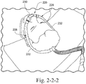
- Figs. 2-2-1 and 2-2-2 illustrate a mask 220 including an interfacing structure 230 and two tubes or inlet conduits 232 extending along respective sides of the patient's face and adapted to deliver breathable gas to the interfacing structure 230.
- Examples of such a mask are disclosed in U.S. Patent Application Nos. 11/878,933, filed July 27, 2007 (published as US 2008/0047560 A1 ) and 11/878,932, filed July 27, 2007 (published as US 2008/0060649 A1 ).
- each of the inlet conduits 232 may include one or more vent orifices 228 for gas washout.
- the orifices 228 may be provided in a region adjacent the interfacing structure 230 (see Fig. 2-2-1 ) and/or the orifices 228 may be provided along the length of each conduit 232 (see Fig. 2-2-2 ).
- the orifices 228 may be arranged in any suitable pattern on the conduit (e.g., random, aligned in columns, etc.) and may be arranged to direct washout gas in any suitable direction.
- each conduit may have any suitable number of orifices, and each orifice may have any suitable cross-sectional configuration along its length (e.g., tapered).
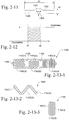
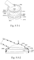
- a vent arrangement for a mask may be provided at the top of the patient's head in order to redirect vent exhaust away from the patient and bed partner.
- the inlet conduits extend to the top of the patient's head and are coupled to one another via a manifold.
- each of the inlet conduits 232 may include one or more vent orifices 228 for gas washout in a region adjacent the manifold 235 (see Fig. 2-3-1 ) and/or one or more vent orifices 228 may be provided in the manifold 235 itself (see Fig. 2-3-2 ).
- the orifices 228 may be arranged in any suitable pattern on the conduit (e.g., random, aligned in columns, etc.) and may be arranged to direct washout gas in any suitable direction.
- each conduit may have any suitable number of orifices, and each orifice may have any suitable cross-sectional configuration along its length (e.g., tapered).
- the mask frame 324 for a mask may include multiple vent orifices or clusters of vent orifices 328 spread out all over the frame 324 to diffuse gas washout.
- the vent orifices may be clustered in selected regions of the frame and/or the vent orifices may be distributed over the frame.
- the frame may have any suitable number of orifices, and each orifice may have any suitable cross-sectional configuration along its length (e.g., tapered).
- the mask may include multiple, adjacent vent orifices 428, and pyramidal or conical shaped protrusions 440 may be provided adjacent the vent exits to fill in viscous shearing regions and therefore reduce noise.
- protrusions 440 are provided to fill in these voids to reduce this shearing region and therefore reduce noise generated.
- the mask may include multiple, closely spaced vent orifices 528 with each vent orifice 528 having an hourglass shape, i.e., vent orifice 528 including the combination of a convergent orifice and a divergent orifice.
- each vent orifice 528 includes an inlet portion 528(1) with a convergent configuration (i.e., orifice tapers from larger to smaller cross-section) and an outlet portion 528(2) with a divergent configuration (i.e., orifice tapers from smaller to larger cross-section).
- the inlet portion 528(1) to the orifice may be rounded off or include a radius to minimize entrance effects.
- Hourglass-shaped orifices enable longer holes to be molded as the convergent inlets and divergent outlets are formed from tooling (pins) on opposite sides that meet at the "neck". Longer holes provide a longer flow path which helps to fully develop the flow.
- an obstruction may be provided in front of the inlet to the vent orifice to significantly reduce the vent inlet velocity and therefore reduce vent noise.
- Fig. 2-7-1 illustrates ResMed's Mirage mask 620 including a mask frame 624, an insert 627 including a plurality of vent orifices 628 provided to the frame, and an inlet tube 622 provided to frame and adapted to deliver pressurized gas.
- the direct flow of air into the vent inlets of the orifices 628 produces high velocity, laminar flow which can generate relatively high vent noise.
- an obstruction 638 e.g., side wall extending from frame
- the obstruction 638 may be placed in front of the vent inlets of the orifices 628 to create resistance and reduce flow velocity and generated vent noise. That is, the obstruction 638 reduces high velocity gas from directly entering the orifices 628, which reduces noise.
- the sound power of the vents is very sensitive to exit vent flow velocity.
- W radiated sound power
- S cross-sectional area of the vent
- ⁇ density of air
- V vent exit flow velocity
- c speed of sound.
- the exit vent flow velocity may be reduced in order to reduce noise.
- a portion of the mask may be provided with a stainless steel mesh 742 that includes plurality of vent orifices 728 for gas washout.
- the stainless steel mesh 742 includes wires 743 that are woven with one another to create the mesh structure with the plurality of vent orifices 728.
- the venting or permeability provided by the mesh 742 may depend on the wire size and the tightness of the weave, e.g., orifice area may be around 25% of the total area of the mesh and the minimum orifice size may be dictated by the minimum stainless steel wire diameter as the wires weave in and out of one another.
- the mesh may be constructed from other woven fabrics or meshed media, e.g., polypropylene, polycarbonate, polyamide (e.g., nylon), polyesters, polytetrafluoroethylene (e.g., Teflon), 3-dimensional spacer fabrics.
- polypropylene polypropylene
- polycarbonate polycarbonate
- polyamide e.g., nylon
- polyesters polytetrafluoroethylene (e.g., Teflon)
- 3-dimensional spacer fabrics e.g., polypropylene, polycarbonate, polyamide (e.g., nylon), polyesters, polytetrafluoroethylene (e.g., Teflon), 3-dimensional spacer fabrics.
- Vent arrangements including fine meshing, textiles, fragile construction of materials, and/or very small orifices are potentially prone to blockage from dirt and bio-build-up or damage. Therefore, the user either needs to regularly wash the vents or replace them to ensure that adequate vent flow is maintained for good CO 2 washout.
- the positive airway pressure device (PAP) device or flow generator may include an alarm to signal the user in the event of reduced vent flow so that the user knows when to replace/wash the vent arrangement. Fail-safe modes are also ways to ensure that the user is cautioned to replace/wash their vents. For instance, if the vent media were assembled to the mask with an adhesive, the adhesive could be CO 2 -sensitive/H 2 O-sensitive which would gradually dissolve with a pre-determined exposure to exhaled CO 2 /humidity. Eventually, the vent media may become loose and may expose a gap (between the vent media and mask) which would still allow for the exhaustion of exhaled gases, however, it may be quite noisy.
- vent component has a preloaded assembly feature that gradually relaxes (i.e., creeps) with time resulting in a loosely fitting vent that would expose a gap between the vent component and the mask interface to which it is assembled.
- a hydrophobic coating may be provided on the inside of the vent material, i.e., hydrophobic coating along the vent inlets.
- the hydrophobicity of the vent inlets will help to prevent the vent orifices from being blocked by humidity.
- the mask may include a dome-shaped portion 845 and a cluster of fine vent orifices 828 distributed over the dome-shaped portion 845 for gas washout.
- the orifice arrangement includes a central orifice and a plurality of orifices arranged in a circle about the central orifice.
- the orifices 828 are separated from one another by a distance x and each orifice 828 has a diameter size d.
- the orifices may be distributed over the dome in other manners, e.g., random, linearly, other patterns, etc.
- Computational Fluid Dynamics may be used to model variation in orifice size and orifice separation to achieve an optimum balance of these two parameters in an attempt to mimic the diffusive properties of membranes such as Gore-TexTM.
- the orifices may be molded out of a sheet of silicone rubber or elastomer and the sheet may be subsequently stretched over a support structure or railing (provided to the mask) structured to curve the sheet into a dome shape.
- the vent arrangement may be constructed in other suitable manners.
- the mask may include multiple vent orifices with adjacent vent orifices having a different size, e.g., alternating smaller and larger vent orifices. Such arrangement may reduce noise in use.
- the amount of generated vent noise is very sensitive to the difference in velocity between the exit vent flow and the velocity of the air surrounding the exit vent stream (i.e., typically the ambient air, which is relatively still).
- the vent arrangement may include a cluster of vent orifices distributed over a portion of the frame for gas washout.
- the vent orifices 928 are arranged within a circular area having a diameter d, and the orifices 928 have different sizes.
- the cluster includes a central or inner orifice 928(1) having a first diameter d1, a plurality of middle orifices 928(2) (e.g., six orifices) regularly spaced and separated from one another along a circle about the inner orifice 928(1) and each having a second diameter d2 that is larger than diameter d1, and a plurality of outer orifices 928(3) (e.g., eight orifices) regularly spaced and separated from one another along a circle that is concentric with the middle orifices 928(2) and each having a third diameter d3 that is larger than diameter d2.
- a central or inner orifice 928(1) having a first diameter d1
- a plurality of middle orifices 928(2) e.g., six orifices
- a plurality of outer orifices 928(3) e.g., eight orifices
- the vent arrangement includes adjacent orifices of different size to reduce noise. Specifically, as shown in Fig. 2-10-2 , the vent arrangement gradually creates different levels of velocity shrouds going from inside to outside a cluster of vent orifices. As illustrated, the velocity shroud is highest on the inner orifice 928(1) and lowest on the outer orifices 928(3) to help reduce the velocity gradient between the highest velocity, central stream and the slow moving ambient air.
- the number of orifices, size, length, spacing, and/or general layout may include a range of different permutations, e.g., non-circular arrangement of orifices.
- a portion of the mask may be provided with a stainless steel mesh that includes plurality of vent orifices for gas washout.
- the stainless steel mesh may be heavily coated with a hydrophobic material. If the hydrophobic coating is sufficiently thick, the coating can help to block up the typically large orifice size defined in stainless steel woven meshes such as the mesh 742 described above.
- a hydrophobic mesh/fabric such as that described above may be a medical grade filtration mesh with an extremely consistent, fine, orifice size, e.g., mesh and fabric available from Sefar.
- the mask may include a vent orifice 1028 and a cap 1050 that covers the vent orifice 1028 to define a small gap or vent passage 1026 that directs gas washout to an outlet remote from the mask, e.g., similar to the slot-orifice vent in ResMed's UltraMirage mask.
- the cap 1050 may include an arcuate portion 1051 adjacent the vent outlet.
- the thin slot or vent passage 1026 provides for much greater effective area to encourage a long flow path to fully develop flow, thereby reducing the amount of generated vent noise.
- the effective venting area is just the area of the small orifice at 1028.
- the relatively large vent cap radius, half d1 provides for a long flow path.
- the orifice size may be selected so that it is both cleanable and quiet.
- the diameter range between d1 and d2 of the orifice may be between about 0.4 - 0.8 mm.
- a larger diameter orifice is easier to clean, however the larger the orifice the nosier the orifice.
- Such orifice size may vary, e.g., depending on frame thickness, desired cleanability and/or quietness, etc.
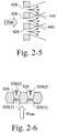
- the mask vent may be in the form of an insert that is provided to a mask (e.g., snap-fit into position) and defines a plurality of vent orifices.
- the insert 1160 is constructed of a molded/stamped sheet of plastic (e.g., polypropylene with thickness in the range of about 0.5 - 0.8 mm) having a plurality (e.g., Figs. 2-5 or 3 ) of perforated sections 1162(1), 1162(2), 1162(3) that are folded against each other to produce a three-dimensional matrix of finer, porous vent orifices.
- the first section 1162(1) includes a series of slots 1163(1) arranged at a first angle
- the second section 1162(2) includes a series of slots 1163(2) arranged at a second angle
- the third section 1162(3) includes a series of slots 1163(3) arranged at a third angle.
- the first angle is about 135° from horizontal
- the second angle is about 45° from horizontal (i.e., perpendicular to the first angle)
- the third angle is vertical or about 90° from horizontal.
- the slots may be arranged at other varying angles.
- each of the slots has a similar width.
- the slots may have varying widths, which may vary from slots in other sections.
- the sections 1162(1), 1162(2), 1162(3) are joined to one another by integral hinges 1164 (e.g., reduced width, slotted edges between sections) to facilitate folding. Also, ends of the first and third sections 1162(1), 1162(3) may includes locking snaps or tabs 1165 structured to retain the insert in its folded configuration.
- the slots 1163(1), 1163(2), 1163(3) overlap one another to provide fine, porous vent orifices through the insert 1160.
- the insert 1160 may be unfolded or opened for cleaning and/or quick drying.
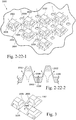
- Figs. 2-14-1 to 2-14-3 illustrate another aspect of a vent insert 1260 for a mask.
- the vent insert 1260 includes a plurality of grill components 1270(1), 1270(2), 1270(3), 1270(4) that are stacked on top of one another to produce a three-dimensional matrix of finer, porous vent orifices.
- the vent insert 1260 includes a cylindrical base 1265 that provides a flange or shoulder 1266 adapted to support the base within an outlet opening in the mask.
- a grill 1268 e.g., one or more cross-bars defining a series of slots is provided to an upper portion of the base 1265.
- the upper portion of the base 1265 includes an annular rim 1267 adapted to support a plurality of disk-like grill components 1270(1), 1270(2), 1270(3), 1270(4).
- four grill components 1270(1), 1270(2), 1270(3), 1270(4) are provided to the base 1265.
- more or less grill components may be used, e.g., 1, 2, 3, 4, or more grill components.
- Each disk-like grill component 1270(1), 1270(2), 1270(3), 1270(4) includes a grill 1272 defining a series of slots and an annular rim 1274 adapted to interlock with the base 1265 and/or other grill components.
- the upper edge of the annular rim includes diametrically opposed protrusions 1276 and the lower/outer edge of the annular rim includes a series of recesses 1278 (e.g., twelve recesses) regularly spaced and separated from one another.
- a first grill component 1270(1) is coupled to the base 1265 by interlocking selected recesses 1278 with the diametrically opposed protrusions 1269 provided on the annular rim 1267 of the base 1265.
- the first grill component 1270(1) may be selectively rotated and interlocked with the base 1265 in order to adjust the angle of its grill 1272 with respect to the grill 1268 of the base 1265.
- the second grill component 1270(2) may be selectively coupled to the first grill component 1270(1) by interlocking selected recesses 1278 with the diametrically opposed protrusions 1276 provided on the first grill component 1270(1).
- the third grill component 1270(3) may be selectively coupled to the second grill component 1270(2), and the forth grill component 1270(4) may be selectively coupled to the third grill component 1270(3).
- the grill components 1270(1), 1270(2), 1270(3), 1270(4) may be selectively rotated and interlocked in order to adjust the angle of the grills 1272 with respect to one another. That is, the grill components 1270(1), 1270(2), 1270(3), 1270(4) may be stacked in different configurations to create different arrays of vent orifices through the insert.
- the insert 1260 may be uncoupled or unstacked for cleaning and/or quick drying.
- Figs. 2-15-1 to 2-15-3 illustrate another example of a vent insert 1360 for a mask.
- the vent insert 1360 includes media 1380 (e.g., (anti-bacterial) filter, membrane, fabric, mesh, or other porous material) to diffuse flow.
- media 1380 e.g., (anti-bacterial) filter, membrane, fabric, mesh, or other porous material
- the vent insert 1360 includes a cylindrical base 1365 that provides a flange or shoulder 1366 adapted to support the base within an outlet opening in the mask (e.g., base secured to mask by friction-fit, adhesive, etc.).
- a grill 1368 e.g., one or more cross-bars defining a series of slots is provided to a lower portion of the base 1365. The grill or cross-bar(s) 1368 prevents inadvertent touching of the vent media during mask handling, and thereby minimizes the contamination of the vent media through handling.
- the upper portion of the base 1365 includes an annular rim 1367 adapted to support at least one or more media 1380, e.g., one or more layers, e.g., two layers. Also, a plurality of snap-fit tabs 1375 (e.g., four snap-fit tabs) extend upwardly from the rim. The tabs 1375 are adapted to interlock with a cover 1385 structured to maintain the media 1380 within the base 1365.
- the cover 1385 includes an annular side wall 1386 and a cross-bar 1387.
- An edge of the side wall includes an engagement flange 1386(1) adapted to engage within a recess 1375(1) provided in each of the tabs 1375 with a snap-fit.
- the cross-bar 1387 prevents inadvertent touching of the vent media during handling of the mask to minimize contamination of the vent media (e.g., from body oils, hand moisturizers, etc.).
- At least one media 1380 is selected (e.g., (anti-bacterial) filter, membrane, fabric, mesh, or other porous material) and inserted within the base 1365, and the cover 1385 is snap-fit to the base 1365 to retain the media 1380 therein.
- the vent flow is diffused as it passes through the grill 1368 and media 1380 of the insert 1360, which reduces noise.
- the cover 1385 may be removed to clean and/or replace the media 1380.
- the base 1365 and cover 1385 may be molded of a plastic material to define a plastic casing for the at least one media 1380.
- the at least one media 1380 may be overmolded or adhered to the casing.
- the entire vent insert 1360 may be replaced (i.e., replaceable cartridge), rather than replace the individual media.
- Figs. 2-16-1 to 2-16-3 illustrate another example of a vent insert 1460 for a mask.
- the vent insert 1460 includes two layers of media 1480(1), 1480(2) (e.g., (anti-bacterial) filter, membrane, fabric, mesh, or other porous material) to diffuse flow.
- media 1480(1), 1480(2) e.g., (anti-bacterial) filter, membrane, fabric, mesh, or other porous material
- the vent insert 1460 includes a cylindrical base 1465 that provides a flange or shoulder 1466 adapted to support the base within an outlet opening in the mask.
- a grill 1468 defining a series of slots is provided to a lower portion of the base 1465. The grill 1468 prevents inadvertent touching of the vent media during mask handling, and thereby minimizes the contamination of the vent media through handling.
- the upper portion of the base 1465 includes a lower annular rim 1467(1) adapted to support a first media 1480(1) and an upper annular rim 1467(2) adapted to support a second media 1480(2). Also, an engagement flange 1475 extends upwardly from the upper rim and is adapted to engage a cover 1485 structured to maintain the first and second media 1480(1), 1480(2) within the base 1465.
- the cover 1485 includes a ring portion 1486 and a cross-bar 1487.
- An edge of the ring portion 1486 is adapted to engage the flange 1475 provided to the base 1465.
- the cross-bar 1487 prevents inadvertent touching of the vent media during handling of the mask to minimize contamination of the vent media (e.g., from body oils, hand moisturizers, etc.).
- the perimeter of the base 1465 includes a recessed side wall and a series of slots 1482 extending through the side wall.
- a cylindrical band 1483 e.g., filter or other suitable permeable media is provided to the recessed side wall and covers the slots 1482.
- a first media 1480(1) is selected (e.g., (anti-bacterial) filter, membrane, fabric, mesh, or other porous material) and inserted into the lower rim 1467(1) of the base 1465
- a second media 1480(2) is selected (e.g., (anti-bacterial) filter, membrane, fabric, mesh, or other porous material) and inserted into the upper rim 1467(2) of the base 1465
- the cover 1485 is engaged with the base 1465 to retain the media 1480(1), 1480(2) therein.
- the cover 1485 includes an annular protrusion 1469 adapted to engage an upper surface of the second media 1490(2) to secure the same in position.
- first and second media may include similar structures (e.g., material, thickness, etc.), or the first and second media may include structures that are different from one another. Also, the first and second media may include different diameters (as illustrated) or the first and second media may include similar diameters (with the base structured to support the same).
- the vent flow is diffused as it passes through the grill 1468 and first and second media 1480(1), 1480(2) of the insert 1460, which reduces noise.
- the vent flow may pass through the slots 1482 and band 1483 between the first and second media 1480(1), 1480(2) to diffuse the flow.
- the cover 1485 may be removed to clean and/or replace the first and second media 1480(1), 1480(2).
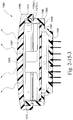
- Figs. 2-17-1 to 2-17-3 illustrate another example of a vent insert 1560 for a mask.
- the vent insert 1560 includes pleated media 1580 (e.g., (anti-bacterial) filter, membrane, fabric, mesh, or other porous material) to diffuse flow.
- pleated media 1580 e.g., (anti-bacterial) filter, membrane, fabric, mesh, or other porous material
- the vent insert 1560 includes a cylindrical base 1565 that provides a flange or shoulder 1566 adapted to support the base within an outlet opening in the mask.
- a grill 1568 defining a series of slots is provided to a lower portion of the base 1565. The grill 1568 prevents inadvertent touching of the vent media during mask handling, and thereby minimizes the contamination of the vent media through handling.
- the upper portion of the base 1565 includes an annular rim 1567 adapted to support media 1580 having a plurality of pleats or folds. Also, an engagement flange 1575 extends upwardly from the rim and is adapted to engage a cover 1585 structured to maintain the media 1580 within the base 1565.
- the cover 1585 includes a ring portion 1586 and a cross-bar 1587.
- the cross-bar 1587 prevents inadvertent touching of the vent media during handling of the mask to minimize contamination of the vent media (e.g., from body oils, hand moisturizers, etc.).
- the edge of the ring portion 1586 includes a recess and adapted to engage the flange 1575 provided to the base 1565.
- a pleated media 1580 is selected (e.g., (anti-bacterial) filter, membrane, fabric, mesh, or other porous material) and inserted within the base 1565, and the cover 1585 is engaged with the base 1565 to retain the media 1580 therein.
- a pleated media 1580 is selected (e.g., (anti-bacterial) filter, membrane, fabric, mesh, or other porous material) and inserted within the base 1565, and the cover 1585 is engaged with the base 1565 to retain the media 1580 therein.
- the vent flow is diffused as it passes through the grill 1568 and the pleated media 1580 of the insert 1560, which reduces noise.
- the cover 1585 may be removed to clean and/or replace the pleated media 1580.
- the use of pleated media allows for a greater area of lower air permeability, venting media to be used whilst still maintaining the footprint within a relatively small area. The lower the air permeability of the venting media, the more effective it is at reducing noise and diffusing air flow as it is much more restrictive to flow.
- media e.g., (anti-bacterial) filter, membrane, fabric, mesh, or other porous material
- vent arrangement e.g., vent insert
- Media may be selected from a range of materials, properties, and manufacturers.
- exemplary media may be disposable and/or hydrophobically treated and may be in the form of a plastic mesh, stainless steel mesh, 3D spacer fabric, felt, and/or membranes (e.g., PALL, Gore-Tex, GE Energy).
- plastic mesh stainless steel mesh
- 3D spacer fabric 3D spacer fabric
- felt 3D spacer fabric
- membranes e.g., PALL, Gore-Tex, GE Energy
- PALL BB Filter hydrophobic
- GE Energy ePTFE membrane Gore-Tex ePTFE membrane
- Sefar PP mesh 05-1001-K120 Sefar PP mesh 05-1001-K079
- Sefar PP mesh 05-8000-K085 3D spacer fabric SPC-121
- Sefar SS mesh 165/1400 Sefar PET mesh 07-88-K080 double layer
- Sefar PET mesh 07-88-K080 double-layer-gap Sefar PET mesh 07-88-K060 double layer
- Sefar NFW-PEPE-384-CS17 Transpor Drylayer woven wicking fabric, reticulated foam, and/or 3M 8710E non-woven.
- Advantages of the plastic mesh include: hydrophobic treatment, small footprint, humidification, biocompatible, and/or simple automated punching and overmolding.
- Advantages of the stainless steel mesh include high perceived value, robustness, and/or biocompatible.
- Advantages of the 3D spacer fabric include small footprint and/or humidification.
- Advantages of the felt include semi-hydrophobic, control of permeability with density, and/or less expensive.
- Advantages of the membranes include pleating, cost, hydrophobic. "high tech", and/or biocompatible.
- the media may be constructed of an electrically conductive material that allows a current to pass through the media, e.g., to dry the media during and/or after use and prevent water vapor from clogging the vent openings.
- the vent arrangement may be a common component structured for use in multiple interface types.
- Figs. 2-18-1 to 2-18-3 illustrate the vent insert 1360 shown in Figs. 2-15-1 to 2-15-3 provided to three different types of interfaces.
- the vent insert 1360 is attached to the mask frame 1624 of a mask.
- the vent insert 1360 is attached to the mask elbow 1627 of a mask.
- the vent insert 1360 is attached to the end of a frame 1629 for a nasal prong arrangement. The interchangeability of the vent insert 1360 facilitates manufacturing and replacement.
- vent flow for a single large outlet with a relatively short flow path produces relatively high velocity flow.
- Such high velocity flow is considered a "jet stream", generating large changes in speed directly outside the outlet.
- Such arrangement generates high jet noise.
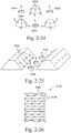
- Fig. 2-19 is a schematic of the velocity shrouds described above with respect to Fig. 2-10-2 for example.
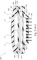
- Fig. 2-20 illustrates an example of a dual flow mouthpiece 1790 for an air compressor.
- This example illustrates an application of the theory in Fig. 2-19 to reduce noise of the jet stream.
- the dual flow mouthpiece 1790 includes a central conduit 1792 that provides a fast inner stream and an outer annular conduit 1794 that provides a slow outer stream. Such arrangement produces less noise than a mouthpiece having a single conduit or stream.
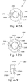
- Figs. 2-21-1 to 2-21-4 illustrate an elbow assembly 1845 according to an aspect of the present disclosure.
- the elbow assembly 1845 includes a vent arrangement that allows part of the vented gas to move at a slower speed outside a faster central stream to reduce noise.
- Such vent arrangement may be adapted for use with elbow assemblies described in U.S. Provisional Application No. 60/924,359, filed May 10, 2007 .
- such vent arrangement may be applied to other portions of a mask, e.g., mask frame.
- the elbow assembly 1845 includes an elbow 1846 and a cover 1850 releasably attached to the elbow 1846.
- the elbow 1846 includes a first end 1846(1) for releasably engaging with an opening in a mask frame and a second end 1846(2) for releasably engaging with a swivel.
- Each of the first and second ends 1846(1), 1846(2) include a plurality of resilient flexible arms 1847 adapted to engage the frame/swivel with a snap-fit.
- the main body of the elbow 1846 includes a venting area which includes a plurality of vent orifices 1828 for gas washout. As best shown in Figs. 2-21-3 and 2-21-4 , each vent orifice 1828 tapers from a smaller cross-section at the vent inlet to a larger cross-section at the vent outlet.
- a pair of lugs 1848 (only one being visible in Fig. 2-21-1 ) are provided on opposing sides of the venting area. The lugs 1848 are adapted to engage respective retaining members 1851 (see Fig. 2-21-2 ) provided on an inside surface of the cover 1850. Also, one or more tabs 1849 (see Fig.
- the taper direction of the vent orifices may be reversed, i.e., from larger cross-section at the inlet to smaller cross-section at the outlet.
- the elbow 1846 includes a baffle 1852 adjacent to where the elbow 1846 is attached to the mask frame.
- the baffle 1852 has a generally U-shape and is arranged to divide the upper arm of the elbow into an air delivery passage and an exhaust passage.
- the cover 1850 includes a venting area which includes a plurality of vent clusters 1854 for gas washout.
- each vent cluster 1854 includes a tubular spigot that defines an orifice 1856 that tapers from a larger cross-section at the inlet to a smaller cross-section at the outlet, and a plurality of arcuate shaped orifices 1858 (e.g., 4 orifices) regularly spaced and separated from one another along a circle about the spigot and each having a cross-section that tapers from a larger cross-section at the inlet to a smaller cross-section at the outlet.
- the taper direction of the orifices may be reversed, i.e., from smaller cross-section at the inlet to larger cross-section at the outlet.
- each vent cluster 1854 of the cover 1850 is aligned with a respective orifice 1828 of the elbow 1846 such that the spigot of each vent cluster 1854 extends partially within the respective orifice 1828 of the elbow 1846.
- vent flow passes through the orifices 1828 of the elbow 1846 and into respective vent clusters 1854 of the cover 1850.
- the flow passing through the orifice 1856 of the spigot is faster than the flow passing through the orifices 1858 outside the spigot.
- the extra, slower outer stream can reduce vent noise in use.
- Such arrangement also allows pins with a thickness of 0.7 mm or less to be used to mold very small holes, i.e., the arcuate orifices 1858 around the central orifice 1856.
- normal molding pins having a diameter of less than 0.7 mm are not particularly robust for use in tooling for molds.
- D 1 may be about 1.76 mm
- D 2 may be about 0.7 mm
- D 3 may be about 0.3 mm
- D 4 may be about 1.13 mm
- D 5 may be about 1.6 mm
- D 6 may be about 2.6 mm
- D 7 may be about 2.5 mm
- D 8 may be about 1.5 mm
- D 9 may be about 2 mm.
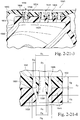
- Figs. 2-22-1 and 2-22-2 illustrate a vent arrangement 2000 according to another aspect of the present disclosure.
- the vent arrangement 2000 includes one or more protrusions 2002 provided to a venting area 2004 of the mask, and one or more vent openings 2006 are provided in side walls of each protrusion 2002 to vent washout gas.
- one or more vent openings 2008 may be provided in the venting area adjacent the protrusions 2002 to vent washout gas.
- washout gas from the vent openings 2006 in the protrusions 2002 and washout gas from the vent openings 2008 in the adjacent venting area are directed into one another to diffuse the air flow, which results in more diffused venting.
- the adjacent streams may also be slightly offset to avoid direct collision of the streams to minimize turbulent noise yet still provide some degree of diffusion.
- each protrusion 2002 is in the form of a truncated pyramid, and a vent opening 2006 is provided through each side wall of the pyramid, i.e., four vent openings 2006 per pyramid.
- any suitable number of openings may be provided to each pyramid, e.g., multiple openings in each side wall, opening in only selected side walls, opening in at least one side wall, etc.
- each opening 2006 has a generally trapezoidal shape, e.g., height of about 0.2-0.6 mm (e.g., 0.4 mm).
- the openings may have other suitable shapes, sizes, and/or arrangement, e.g., circular, tapered along its length, etc.
- the protrusions 2002 are arranged corner to corner in a spaced-apart, grid-like manner. Such arrangement defines multiple venting areas between the protrusions 2002 in which respective vent openings 2008 are provided.
- vent openings 2008 are provided in other suitable arrangements.
- other suitable arrangements of the protrusions are possible, e.g., random, circular, rows, columns, etc.
- openings 2008 may simply not be provided.
- each opening 2008 has a generally circular shape.
- the openings 2008 may have other suitable shapes, sizes, and/or arrangement, e.g., non-circular, tapered along its length, etc.
- the protrusions 2002 are structured to increase the surface area available for venting so more vent openings may be provided over a venting area of the mask.
- the protrusion 2002 provides four vent openings 2006 in a similar area as each vent 2008.
- vent openings 2006 in the protrusions 2002 and the vent openings 2008 in the base wall 2005 are arranged so that washout gas is directed in different directions, into one another and/or slightly offset from one another to create diffuse air flow, e.g., see Fig. 2-22-1 .
- the protrusions may have other suitable shapes or arrangements.
- the protrusions may be star-shaped, crescent-shaped, alphanumerically shaped, logo-shaped, hexagonal, octagonal, etc. That is, the protrusions may have any suitable shape with vent openings arranged to deliver exhaust gases in a direction that is not parallel to adjacent vent orifices.
- the lower edge of the vent openings 2006 may align with the base wall 2005, rather than be spaced upwardly from the base wall 2005 as in Figs. 2-22-1 and 2-22-2 .
- the inner base wall or interior surface of protrusion 2002 may be shaped rather than planar (as shown in Figs. 2-22-2 and 2-22-4 ), for example angular or rounded. This arrangement may direct the air stream out of vent openings 2006 in a smoother pathway, thereby reducing turbulent flow and thus noise.
- Fig. 2-22-5 is a schematic view of a mold for molding the protrusions of Figs. 2-22-3 and 2-22-4 .
- upper and lower molds UM, LM cooperate to define the top of the protrusions, the base wall, and the vent openings therebetween.
- each of the protrusions may have an inverted configuration, e.g., truncated pyramid-shaped recess that extends inwardly from the base wall 2005 and into the breathing cavity.
- a vent opening 2007 may be provided in the bottom wall of each truncated pyramid-shaped recess rather than the base wall 2005 to create diffuse flow.
- each protrusion may have a dome-shape with vent openings 2006 provided along the dome.
- each protrusion may be in the form of an elongated three-dimensional trapezoid with vent openings 2006 along side walls thereof. As illustrated, the 3-D trapezoids may be spaced apart to define venting areas therebetween in which vent openings 2008 are provided.
- the protrusion may be provided as a separate component from the mask that is adapted to be attached or retrofit to the mask including one or more vent openings. That is, the protrusion may be secured in position (e.g., glued, snap-fit, etc.) over a selected vent opening to cover the vent opening and provide diffused vent flow as gas passes therethrough in use.
- Fig. 2-26 illustrates a vent arrangement 2100 according to another aspect of the present disclosure.
- the vent arrangement 2100 is structured to be connected between the mask and the air delivery conduit.
- the vent arrangement 2100 includes a plurality of disks 2195 adapted to be stacked on top of one another.
- a plurality of the disks 2195 e.g., every disk in the stack, every other disk in the stack, etc.
- vent openings 2197 e.g., curved recesses
- the disks may be coupled to one another (e.g., slinky-like arrangement) to create a one-piece structure, e.g., to facilitate cleaning and reduce the risk of losing small parts.
- Fig. 3 provides a chart illustrating sound power for vent media described above. As illustrated, at 10 cmH 2 O, the sound power for vent media described above may range from about 22 dBA to about 45 dBA for a flow rate of about 6-57 L/min, and at 20 cmH 2 O, the sound power may range from about 28-35 dBA for a flow rate of about 23-42 L/min.
- the standard vent can be, for example, the vent arrangement shown in Fig. 4-1A .
- the vent media may be selected based on sound requirements, preferences, etc. For example, in an example, the vent may be quieter than about 30 dBA. In another example, the vent may be quieter than about 25 dBA.
- the sound power for the vent media may be dependent on the coarseness of the fibers in each vent media, the size of the holes in the vent media, and/or the flow path through the vent media.
- the fibers in the vent media may not be coarse so as to avoid turbulent flow.
- ePTFE membrane may have flaws and variations throughout the membrane and therefore may cause higher noise levels particularly at higher flow rates.
- the size of the holes in the vent media may be small, for example, the stainless steel meshes may have small vent holes that emit an acceptable level of noise.
- the flow path through the vent media may be generally long and direct, forming for example a continuous tunnel.
- the flow path through the PP mesh may be more direct (due to the arrangement of fibers) than that through the reticulated foam or woven wicking fabric thereby reducing the noise emitted from the PP mesh than the foam.
- Fig. 4-1A to 4-7D illustrate vent arrangements according to various aspects of the present disclosure.
- the mask vent is in the form of a vent cap structured to be releasably attached to an opening or venting area of the mask.
- the vent cover includes a plurality of vent holes constructed and arranged to diffuse airflow leaving the mask in use.
- Figs. 4-1A to 4-1C illustrate vent caps according to alternative aspects of the present disclosure
- Fig. 4-1A illustrates a vent cap 2200 including multiple vent holes 2230 arranged on a base wall to direct airflow away from the patient's face in use.
- Fig. 4-1B illustrates a vent cap 2300 for a vent arrangement according to an embodiment of the present invention, the vent cap 2300 including multiple vent holes 2330 arranged on an annular side wall to provide diffuse airflow that is directed away from the patient's face as well as the bed partner. The angle of the diffused airflow can be tuned by altering the dimensions of the vent cap.
- Fig. 4-1C illustrates a vent cap 2400 including media 2430 (e.g., textile, filter, membrane, fabric, mesh, or other porous material or means of ventilation) structured to diffuse airflow from the mask.
- media 2430 e.g., textile, filter, membrane, fabric, mesh, or other porous material or means of ventilation
- each vent cap there may be any suitable number of holes distributed around the vent cap.
- Each hole may have any suitable shape, e.g., generally round, square, tapered along its length, etc.
- the holes may be uniform or varying in size and/or shape.
- each hole may be no smaller than about 0.00-0.08 mm in diameter.
- each hole may be no smaller than 0.6-0.8 mm (e.g., 0.7 mm) in diameter. Smaller holes may be preferable as they direct air flows in such a way that they become more fully developed flows.
- the vent cap may include a venting area adapted to be aligned with a venting area of the mask (e.g., elbow) when assembled together to define "full" vent passages, e.g., similar to the arrangement shown in Figs. 2-21-1 to 2-21-4 described above.
- the vent cap may be made from a polymer, such as polypropylene or polycarbonate. However, other suitable materials are possible. Also, the vent cap may be constructed and arranged to be relatively durable, or the vent cap may be constructed and arranged to be less durable, replaceable, and/or disposable.
- the vent cap 2300 for a vent arrangement according to an embodiment of the present invention now be described in greater detail.
- the vent cap 2300 includes a base wall 2335 and a dome 2340 that extends upwardly from the base wall 2335 above the horizontal surface of the base wall 2335.
- the multiple vent holes 2330 are arranged on an annular side wall of the dome 2340.
- the dome 2340 may have a generally hemispherical, trapezoidal, square, or other desired shape.
- the dome 2340 has a low profile, e.g., raised 1-3 mm (e.g., 2 mm) from the horizontal surface of the base wall. This arrangement helps to direct air flow in long, thin paths so as to maintain more fully developed and/or laminar flow.
- the "domed" vent cap directs exhaust flow up and out from the mask, i.e., "domed” vent cap alternates the direction of exhaust flow from a first incoming direction d1 to a second outgoing direction d2 that is sloped or angled with respect to the first direction d1, e.g., substantially perpendicular, as shown in Fig. 4-3B .
- the vent cap constitutes an exhaust divider as the vent holes are arranged to divide the exhaust flow in different directions as it exits the vent cap.
- the vent holes are arranged radially along the annular side wall of the dome 2340 to radially divide the exhaust flow in 360°.
- vent holes may be arranged in other suitable manners radially along the annular side wall of the dome as long as they radially divide exhaust flow over one or more portions totaling at least 90°, e.g., a portion of the circumference from 90° up to 360° (e.g., 270°, 180°, 90°, or anywhere in between), selected arcs or portions of the circumference (e.g., selected portions on opposite sides of the dome).
- Alternative vent hole arrangements on the dome may be selected to direct exhaust gas in certain directions, e.g., away from the patient's face or bed partner. Also, as shown in Fig.
- the vent holes may be configured to direct exhaust gas at an angle with respect to horizontal, e.g., vent holes may direct exhaust in direction d2 or at angles ⁇ 1, ⁇ 2 with respect to d2 (e.g., ⁇ 1, ⁇ 2 about 0-20°).
- the dome 2340 may be any suitable size, but should not be wider than the base wall.
- the outer surface of the dome 2340 may have a smooth finish, e.g., the vent holes 2330 are not raised or sunken into the outer surface of the dome 2340. However, in an alternative embodiment, the holes 2330 may be raised or sunken into the outer surface of the dome 2340.
- each of the vent caps is structured to be releasably attached to the mask by means of a bayonet connection. Attachment of the vent cap 2300 to an elbow 2390 of the mask will now be described in greater detail.
- the vent cap may be releasably attached to another portion of the mask in a similar manner, e.g., mask frame.
- the vent cap may be attached to the mask in other suitable manners, e.g., snap fit, ultrasonically welded (in which case, it would not be a releasable component), interference fit, sliding fit, permanently machined into the mask, etc.
- the vent cap 2300 includes outer and inner side walls (e.g., see Fig. 4-2B ) 2352, 2354 that extend downwardly from the base wall 2335 and define a channel 2356 therebetween.
- Two diametrically opposed projections 2360 extend radially inwardly from the outer side wall 2352.
- the vent cap 2300 includes a window 2358 adjacent each projection 2360 that allows the user to visually recognize when the vent cap 2300 is in a locked position as described below.
- the elbow 2390 includes an opening 2392 for gas washout.
- An annular lip 2394 surrounds the opening 2392 and one or more ribs 2396 (e.g., two diametrically opposed ribs) extend radially outwardly from the lip 2394.
- each rib 2396 is generally L-shaped including a first leg 2396(1) and a second leg 2396(2).
- the second leg 2396(2) is a bayonet "stop" which prevents the vent cap from over-turning and subsequently disengaging.
- the second leg 2396(2) also offers feedback to the user that they have reached the "end" and the vent cap is properly locked.
- Figs. 4-6A to 4-6B and 4-7A to 4-7C illustrate attachment of the vent cap 2300 to the elbow 2390.
- Figs. 4-6A to 4-6B illustrate the vent cap 2300 in an unlocked position with the vent cap 2300 resting on the elbow lip 2394, i.e., channel 2356 receives elbow lip 2394 and ribs 2396 therebetween.
- the outer side wall 2352 of the vent cap 2300 overhangs the elbow lip 2394 such that the projections 2360 are circumferentially spaced from the elbow ribs 2396.
- the vent cap 2300 is rotatable with respect to the elbow 2390 to move the vent cap 2300 to a locked position as shown in Figs. 4-7A to 4-7C .
- the vent cap 2300 is rotated to position the projections 2360 underneath respective first legs 2396(1) of the ribs 2396, and thereby axially lock the vent cap 2300 in position on the elbow 2390.
- the second legs 2396(2) of the ribs 2396 prevent further rotation of the vent cap 2300 with respect to the elbow 2390, i.e., further rotation causes projections 2360 to engage respective second legs 2396(2).
- the window 2358 in the vent cap 2300 allows the user to visually recognize when the first legs 2396(1) of the ribs 2396 are aligned with the projections 2360 and hence locked.
- the bayonet connection provides a relatively simple and intuitive arrangement to use. It also minimizes leak from the vent cap since the connection is radial and does not require an interference to lock the vent cap in position, e.g., like a clip-on vent cover.
- vent cap will diffuse air so that the air flow is undetectable by a person at a distance of less than about 500 mm from the vent, e.g., less than 200 mm, less than 100 mm, less than 50 mm, less than 30 mm.
- vent cap will produce less than about 40 dBA sound power at 10 cmH 2 O tested according to ISO3744, e.g., less than 30 dBA, less than 25 dBA, less than 20 dBA.
- the vent cap has a generally circular shape.
- the vent cap may have other suitable shapes that allow a bayonet connection or other connection mechanism.
- the vent cap 2300 may include an extended edge 2380 that protrudes outwardly from the base wall 2335.
- the ideal vent will be quiet and diffuse. Noise can be minimized by promoting low velocity, fully developed, laminar flow from the vent. Diffuse flow can be achieved by releasing the air flow over a larger area. Vent arrangements are described below that are structured to minimize noise and diffuse flow from the vent though a combination of features.
- vent will be able to maintain flow under saturated or humidified conditions, minimize CO 2 re-breathing, be manufacturable, be cleanable or disposable, and biocompatible.
- air flow that is exiting a mask system will be directed through a vent that is quiet and diffuse.
- noise from the vent will be less than about 30-40 dBA, e.g., less than 35 dBA.
- the vent may be considered "super quiet" when noise is less than about 30 dBA, e.g., about 20-25 dBA.
- a baffle 2500 may be provided between a mask 2520 and an elbow 2540 as schematically shown in Fig. 5-1 .
- the baffle 2500 may be positioned between the elbow 2540 and a frame or cushion of the mask 2520 where air is typically vented from the mask 2520.
- the baffle 2500 is designed to force air exiting the mask 2520 to flow through a narrow pathway.
- the baffle will be wide so that the air will flow through a longer pathway (as compared to a narrow baffle in which the pathway is shorter).
- a longer pathway encourages low velocity, fully developed, laminar flow.
- the baffle is generally circular.
- the baffle may have any suitable shape that closely matches the geometry of the elbow to frame or elbow to cushion connection, e.g., elliptical.
- the baffle will be relatively thin to minimize the weight of the mask system.
- the baffle may not form a completely closed shape, e.g., the baffle may be hemispherical. This arrangement may allow for passage of another apparatus (e.g., anti-asphyxia valve (AAV)) or easier insertion and removal of the baffle.
- AAV anti-asphyxia valve
- the baffle 2500 may have undulations or curves 2502 to force the air to flow over a larger area before exiting the mask system. This will slow the flow of the air producing low velocity, fully developed, laminar flow.
- the baffle may form a part of the elbow.
- the baffle may be a separate part that may be retrofitted to an elbow. If retrofitted, the baffle may be held in place by any suitable means, e.g., interference fit, push fit, adhesive, etc.
- a lip may be provided to the baffle to enhance sealing.
- the baffle may be attached by a bayonet connection.
- the baffle 2500 includes an annular side wall 2510 with one or more male connectors 2512 provided to an exterior surface of the annular side wall 2510.
- the elbow 2540 includes an annular side wall 2542 with a corresponding number of female connectors 2544 (i.e., L-shaped female connectors) provided to an interior surface of the annular side wall 2542.
- the male connectors 2512 are received in the first leg 2544(1) of respective female connectors 2544, and then the baffle 2500 and elbow 2540 are rotated relative to one another to slide the male connectors 2512 into the second leg 2544(2) of respective female connectors 2544.
- the baffle may include female connectors for attachment with male connectors on the elbow.
- the bayonet connection may be positioned on the annular side walls of the baffle and elbow (as shown in Figs. 5-3-1, 5-3-2 , and 5-4 ), or the bayonet connection may be positioned on the mating surfaces of the baffle and elbow (e.g., see Fig. 5-5 ).
- the elbow 2540 includes multiple vent holes 2545 arranged on an annular side wall so that the elbow 2540 and baffle 2550 are arranged to force washout gas generally parallel to the user's face in use.
- vents are positioned so that vent flow from the mask system is perpendicular to the user's face and may possibly jet vent flow onto the bed partner or other interferences such as bedding. Jetting increases noise and discomfort for the bed partner. Vented gas traveling parallel to the user's face tends to avoid these problems by "spreading" the vent flow radially over a larger area rather than concentrating it all in a small region. That is, the vent flow in this arrangement is akin to a distributed load rather than a concentrated load, should it meet with an obstruction in its path.
- the air path 2560 created by the elbow and the baffle will be about 0.01 to 5 mm, e.g., 1 mm.
- the baffle 2500 may not be anchored in one position.
- the baffle 2500 may be able to rotate within the elbow 2540.
- baffles could be used to force air flow out of multiple air paths.
- 2, 3, 4, or more baffles may be stacked and placed between the elbow and the mask.
- the baffle may be about 1-30 mm wide (radially), e.g., 10 mm wide (radially).
- the baffle may be constructed of a hard plastic, e.g., such as polycarbonate.
- the baffle may be constructed from softer materials to absorb more of the sound, e.g., low durometer silicone.
- other suitable materials are possible.
- a single baffle may be used that is coiled to form multiple air paths.
- Fig. 5-6-1 shows the coil-type baffle 2600 in its uncoiled or uncompressed position
- Fig. 5-6-2 shows the coil-type baffle 2600 in its coiled or compressed position between a mask 2620 and elbow 2640.
- the coils cooperate to form multiple air paths along its length.
- one or more grooves may be provided in each coil to define air paths across the coil.
- Such arrangement provides a "stack" of vent rings integrally formed as a one-piece structure.
- tracks or guides may be provided to a vent hole that are structured to force washout gas to flow in long, narrow passages as it exits the mask system.
- Figs. 5-7-1 and 5-7-2 illustrate an elbow 2740 including multiple vent holes 2745 and spaced-apart raised tracks 2747 proximate each vent hole 2745 along the inner surface of the elbow 2740 (i.e., the side of the elbow that is subjected to the pressurized air flow).
- the tracks 2747 are generally rectangular.
- the tracks may have other suitable shapes to direct washout gas, e.g., elliptical.
- the "track" arrangement may also incorporate the use of an annular baffle as shown in Figs. 5-3-1 and 5-3-2 .
- the tracks may extend into the inner surface of the elbow 2740.
- the tracks would resemble indents or recesses. In use, the indented tracks will draw air flow into them and create a long, narrow flow path.
- the tracks may be uniform in length.
- the tracks may vary in length.
- the tracks will be longer than about 2 mm, e.g., 4 mm.
- each vent hole 2745 will have one or more tracks leading to the opening of the hole, e.g., two tracks per vent hole as shown in Fig. 5-7-2 . If there is more than one track for each vent hole, the track may be separated by any suitable amount, e.g., more than about 0.1 mm.
- the tracks may be molded or otherwise formed into the elbow.
- the tracks may be provided in a separate component (e.g., molded into separate component) and retrofitted to the elbow.
- two or more tracks may join together or otherwise cooperate about a vent hole to form a tube (or at least a portion of a tube).
- This tube may have a circular cross section, or any other desired cross section, e.g., square. Similar to the tracks, the tube will direct air flow down a long, narrow pathway to form low velocity, fully developed, laminar flow.
- a baffle with tracks may be provided to an elbow.
- Fig. 5-8-1 illustrates a baffle 2800 including a plurality of tracks 2802.
- the baffle 2800 includes a ring-like structure with each track 2802 extending from an inner radius of the baffle to an outer radius of the baffle.
- groups of tracks 2802 are placed about the baffle.
- the tracks may be arranged in other suitable manners, e.g., continuous around the baffle, randomly arranged.
- each track 2802 extends into the surface of the baffle like an indent or recess.
- each track may be raised from the surface of the baffle.
- each track 2802 may be curved from the inner radius of the baffle to the outer radius of the baffle. This arrangement maximizes the length of the tracks so that the air travels a longer distance and loses velocity.
- each track may have other suitable shape along its length, e.g., straight line or coiled extending from the inner radius to the outer radius of the baffle.
- the tracks 2802 are provided to one side of the baffle 2800. However, the tracks 2802 may be provided to both sides of the baffle (e.g., see Fig. 5-8-3 ).
- Fig. 5-8-2 and 5-8-3 show the baffle 2800 provided to an elbow 2840.
- the elbow 2840 includes one or more windows 2870 about its circumference adapted to receive the baffle 2800.
- the baffle 2800 extends through the windows 2870 and includes cutouts 2804 to receive elbow wall portions 2872 adjacent the windows 2870.
- the baffle 2800 is open ended (e.g., C-shaped) to allow the baffle 2800 to deform slightly during assembly/disassembly to the elbow 2840, e.g., spring like a circlip.
- the baffle 2800 with tracks on one side may reduce noise from the vent by at least 10 dBA when compared to other conventional masks (e.g., ResMed's Mirage Micro).
- a 10 dBA reduction in noise corresponds to half the amount of noise previously emitted.
- a vent cap (as described above in section 4.1) may reduce noise from the vent by at least 3 dBA when compared to other conventional masks.
- a 5 dBA reduction in noise is clearly noticeable when compared to the noise previously emitted.
- a 3 dBA reduction in noise is just noticeable when compared to the noise previously emitted. Therefore, the baffle is highly effective in terms of maximizing noise reduction from the vent and diffusing air flow from the vent.
- Figs. 5-9-1 to 5-9-6 illustrate a baffle or vent ring 3100 for an elbow 3140 according to another aspect of the present disclosure
- the vent ring 3100 has an open-ended C-shaped main body 3101 with L-shaped finger tabs 3103 adjacent the open end (see Fig. 5-9-2 ).
- the main body 3101 includes a plurality of radially arched tracks or grooves 3102 on one or both sides thereof.
- the grooves 3102 extend from an inner radius of the vent ring to an outer radius of the vent ring.
- each groove is open-ended (e.g., U-shaped, V-shaped, semi-circular shaped, etc.) and tapers along its length from the inner radius to the outer radius of the vent ring.
- each groove may be radially arched or curved along its length.
- each groove may include other suitable arrangements, e.g., same width along its length, zig-zag or other tortuous path along its length, different size, different depth, extend at different angle along main body (e.g., longest path from inner radius to outer radius of vent ring), etc.
- the vent ring 3100 is deformable (e.g., like a c-clip or circlip) to assemble/disassemble to the elbow 3140.
- the elbow 3140 includes a slot 3142 adapted to receive and support the vent ring 3100 within the elbow 3140.
- the slot 3142 provides an entry/exit window 3143 to receive the vent ring 3100, upper and lower flanges 3144, 3145 to support the vent ring 3100 within the elbow, and windows 3146 along with entry/exit window 3143 that allow gas washout across the vent ring 3100, and supporting beams 3148 to maintain and align the vent ring 3100 within the elbow 3140.
- the user's fingers may be placed in the gaps defined by the finger tabs 3103 of the vent ring 3100 so as facilitate gripping and squeezing the finger tabs 3103 towards one another, which distorts or deforms the generally round vent ring into an oval shape (see Fig. 5-9-3 ). Since the width of the distorted vent ring 3103 is now less than a width of the entry/exit window 3143 of the elbow 3140, the vent ring 3100 may be slid through the entry/exit window 3103 and into the elbow 3140 (see Fig. 5-9-4 ). When the finger tabs 3103 are released, the vent ring 3100 resiliently springs back into shape.
- vent ring 3100 is held in place by an interference fit, where the width of the vent ring 3100 is substantially the same as that of the entry/exit window 3143.
- the vent ring 3100 includes cutouts 3104 to receive supporting beams 3148 of the elbow 3140 (see Figs. 5-9-1 and 5-9-5 ).
- the vent ring 3100 may be made from a substantially rigid or semi-rigid material. Also, the elbow 3140 provides flanges 3144, 3145 on opposing sides of the vent ring 3100 to support the vent ring 3100 when it is loaded (e.g., pressurized gas flow), thereby preventing bowing of the vent ring 3100 and thus leak (see Fig. 5-9-6 ).
- the grooved vent ring combines with the elbow to define vent orifices, i.e., each vent orifice defined by a part of the vent ring (the groove) and a part of the elbow (upper and/or lower flange).
- vent orifices i.e., each vent orifice defined by a part of the vent ring (the groove) and a part of the elbow (upper and/or lower flange).
- Figs. 5-10-1 to 5-10-3 illustrate a vent ring 3200 according to another aspect of the present disclosure.
- the vent ring 3200 includes a hinge or movable joint 3290 and a locking mechanism 3292 diametrically opposed from the hinge 3290.
- the hinge 3290 allows the vent ring 3200 to pivot open and be wrapped around the slot 3142 in the elbow 3140 (see Fig. 5-10-2 ).
- the locking mechanism 3292 includes a pin and groove arrangement wherein the pin 3292(1) and groove 3292(2) can be pushed together and interlocked (see Fig. 5-10-1 ) to close the arms of the vent ring 3200 around the slot.
- the groove 3292(2) may be provided to a finger tab 3293 with an arched protrusion 3294 to facilitate grip.
- the hinge 3290 is provided by a thinned region of the vent ring 3200 (e.g., cutout 3204 and slot 3291).
- the vent ring 3200 should be somewhat flexible to allow the vent ring 3200 to be deformed (hoop stress) into an unlocked or open position for assembly to the elbow 3140.
- the vent ring 3200 includes a plurality of radially arched tracks or grooves 3202 on one or both sides thereof.
- grooves 3202 are provided on both sides, it is preferable to have the grooves 3202 extending in opposite directions on opposing top and bottom sides so that air streams are exhausted in opposite directions (see Fig. 5-10-3 ), which provides more diffuse exhaust.
- Figs. 5-11-1 and 5-11-2 illustrate a vent ring 3300 and elbow 3340 according to another aspect of the present disclosure.
- the vent ring 3300 is soft and flexible and includes a closed, o-ring shape so that the vent ring 3300 can be stretched or wrapped around the elbow 3340.
- a finger tab 3303 is provided to the vent ring 3300 to facilitate assembly/disassembly to the elbow 3340.
- the elbow 3340 includes a slot 3342 around its perimeter to receive the vent ring 3300.
- the bottom wall of the slot 3342 includes openings 3346 for gas washout and each side wall of the slot 3342 (adjacent each opening 3346) includes a plurality of tracks or grooves 3302.
- the vent ring 3300 forms a seal with the elbow 3340 so that air can only exhaust between the vent ring 3300 and the grooves 3302 on the elbow 3340.
- the soft and flexible vent ring 3300 may dampen sound in use.
- Figs. 5-12-1 and 5-12-2 illustrate a vent ring 3400 and elbow 3440 according to another aspect of the present disclosure.
- This example is similar to the example of Figs. 5-11-1 and 5-11-2 ; in contrast, grooves 3402 are provided on the vent ring 3400, and no grooves are provided on the elbow 3440 (e.g. smooth surface on side walls of the slot 3442). This arrangement may be easier to manufacture.
- the vent ring 3400 includes a plurality of tracks or grooves 3402 along the entire perimeter of the vent ring 3400. This arrangement provides 360° vent flow which may provide more diffuse exhaust.
- a section of the vent ring 3400 may not have grooves, and this section could be aligned with the patient's eyes so that air flow does not irritate the patient's eyes in use.
- Figs. 6-1 to 6-7 illustrate an elbow 3040 including a vent arrangement according to another embodiment of the present invention.
- the vent arrangement is in the form of a diffused vent cap 3000 that is integrally formed in one-piece with the elbow 3040.
- This arrangement provides a single piece elbow with no removable parts, e.g., so patients do not have to disassemble the elbow for cleaning.
- the vent cap may be integrally formed in one piece with other portions of the mask, e.g., mask frame, associated conduit, etc.
- the elbow 3040 includes a first end 3040(1) for releasably engaging with an opening in a mask frame and a second end 3040(2) for releasably engaging with a swivel.
- the first end 3040(1) includes opposing ribs 3046 adapted to engage the mask frame with a snap-fit.
- the first end 3040(1) may also have a long sealing surface 3041 adapted to interface with the mask frame, whereby such a long sealing surface promotes better sealing thereby reducing leak between the elbow and mask frame.
- the sealing surface 3041 may be frosted or textured to prevent noise (for example squeak) created by the friction of two moving parts.
- the first end 3040(1) may also have a stepped arrangement whereby sealing surface 3041 is wider than stepped surface 3042. This may allow for easier disassembly of the elbow from the mask frame. Additionally, scallops or cut outs 3043 may be provided to stepped surface 3042 to allow the stepped surface 3042 to flex inwards thereby enabling disassembly of the elbow from the mask frame.
- the second end 3040(2) includes a plurality of resilient flexible arms 3047 adapted to engage the swivel with a snap-fit. However, the first and second ends 3040(1), 3040(2) may include other suitable structures for engaging the frame/swivel.
- the main body of the elbow 3040 includes a vent cap 3000 integrally formed in one-piece therewith. Similar to the vent cap 2300 described above, the vent cap 3000 includes a base wall 3035, a dome 3040 extending upwardly from the base wall 3035, and multiple vent holes 3030 arranged on an annular side wall of the dome 3040 to provide diffuse airflow that is directed away from the patient's face as well as the bed partner.
- the angle of the diffused airflow can be tuned by altering the dimensions of the vent cap.
- the diffused airflow provides venting over a larger area to avoid jetting and may also reduce noise.
- the elbow 3040 includes a baffle 3052 adjacent to where the elbow 3040 is attached to the mask frame.
- the baffle 3052 has a generally U-shape and is arranged to divide the upper arm of the elbow into an air delivery passage and an exhaust passage, e.g., to enhance CO 2 washout.
- the baffle 3052 is integrally formed with the elbow 3040.
- the baffle may be retrofit to the elbow. Gaps 3053 are provided on either side of the baffle 3052 from the inner surfaces of first end 3040(1) to allow stepped surface 3042 to freely flex inwards when assembled and disassembled to the mask frame.
- Figs. 7-1 to 7-3 illustrate a plug-type vent 3500 and frame 3540 according to another aspect of the present disclosure.
- the plug 3500 is soft and flexible and includes a relatively long and narrow shape (e.g., I-shaped) for insertion into a corresponding I-shaped slot 3542 in the frame 3540.
- the plug 3500 includes a base 3501 and a top lip 3503 extending from the base 3501.
- a plurality of tracks or grooves 3502 are provided along the exterior surface of the base 3501 and the lower surface of the lip 3503.
- the bottom wall of the slot 3542 includes an elongated opening 3546 for gas washout.
- the grooved plug 3500 forms a seal with the slot 3542 so that air can only exhaust between the slot walls and the grooves 3502 on the plug 3500.
- the soft and flexible plug 3500 facilitates attachment to the frame 3540 and may dampen sound in use.
- the grooves 3502 extend along the entire perimeter of the plug, e.g., 360° vent flow, which may allow vent flow to be directed into the patient's eyes.
- the grooves may exit the plug vertically rather than horizontally so as to direct air flow away from the patient's eyes.
- Figs. 8-1 to 8-3 illustrate a plug-type vent 3600 and frame 3640 according to another aspect of the present disclosure.
- the plug 3600 and corresponding slot 3642 have a generally v-shaped configuration.
- the plug 3600 includes a pair of arms 3608 and a connecting portion 3609 connecting the arms 3608.
- a plurality of tracks or grooves 3602 are provided to each arm 3608 and extend along the bottom surface and the outer side of each arm.
- Each arm of the slot 3642 includes an elongated opening 3646 for gas washout.
- the grooves 3602 direct vent flow along sides of the frame and avoid exhaust into the patient's eyes.
- the grooves may extend along the inner side of each arm 3608 so that exhaust could flow out the inner sides and cause air paths to collide.
- Figs. 9-1 to 9-4 illustrate a plug-type vent 3700 and frame 3740 according to another aspect of the present disclosure.
- the plug 3700 and corresponding slot 3742 have a generally u-shaped configuration.
- the plug 3700 includes a pair of arms 3708 and a bight portion 3709 connecting the arms 3708.
- Each arm 3708 includes a plurality of tracks or grooves 3702 on one or both sides thereof and a connecting portion 3711 for engaging the frame 3740.
- each arm 3708 includes a port cap 3715 extending from the connecting portion 3711 and adapted to engage a respective port 3745 provided in the frame 3740.
- the frame 3740 includes a slot 3742 to receive the plug 3700.
- the bottom wall of the slot 3742 includes one or more openings 3746 for gas washout (see Fig. 9-4 ).
- the grooved plug 3700 forms a seal with the slot 3742 so that air can exhaust between the slot walls and the grooves 3702 on the plug 3700.
- the slot walls define an angle ⁇ (e.g., in the range of 5-45°, e.g., 10°) which directs the air stream outwards from the slot 3742.
- the angle ⁇ is not relatively large so as to direct the air stream onto the patient's chest.
- a support beam 3744 is provided in the center of the slot 3742 to maintain spacing between upper and lower slot walls.
- a groove 3717 is provided in the bight portion 3709 of the plug 3700 to receive at least a portion of the support beam 3744, e.g., to align the plug in the slot and enhance the interference fit.
- multiple support beams may be provided.
- the support beams should be sufficiently spaced apart from one another so that sufficient exhaust gas can enter the grooves 3702 on the plug 3700 to provide adequate CO 2 washout.
- baffles may be provided inside the frame to help with CO 2 washout.
- the connecting portion 3711 of each arm includes locking bumps 3713(1), 3713(2) on opposing sides thereof, one of which is adapted to interlock with a retention slot 3747 (see Figs. 9-1 and 9-2 ) provided to the frame 3740 along the slot 3742 (i.e., interference fit).
- a clearance 3749 is provided to the slot 3742 opposite the retention slot 3747 to receive the other of the locking bumps.
- the plug 3700 is adapted to wrap around and under an inlet opening 3751 provided to the frame 3740.
- the plug may be positioned at other suitable locations on the frame.
- port caps 3715 are integrated or incorporated into the plug 3700 (e.g., integrally formed in one piece). Such one-piece arrangement reduces the number of mask parts, prevents loss and/or misplacement of parts (e.g., port cap retained to plug when port cap is unplugged from port), and facilitates manufacturing. It should be appreciated that any suitable number of port caps may be provided to the plug.
- the connecting arm or hinge 3716 connecting each port cap 3715 to the plug 3700 may have any suitable length or thickness (e.g., arm could be wider, thicker, and/or longer), which may depend on material properties and/or desired assembly/disassembly force.
- the connecting arm 3716 is flexible to allow bending of the connecting arm in the plane of the plug 3700 and/or bending or twisting transverse to the plane of the plug 3700. Also, when removing the port cap 3715 from the respective port 3745, the plug 3700 may be maintained in position within the slot 3742, unless removal of the whole plug is desired.
- the plug 3700 is constructed from a soft and flexible material (e.g., silicone, TPE, rubber) to facilitate attachment to the frame and dampen noise in use.
- the plug material may have little to no moisture retention and may not be prone to creep.
- the plug may be made from an opaque elastomer and/or may be a relatively large part so that the plug is harder for the patient to lose.
- the plug 3700 may be made by two shot molding, i.e., a first shot may be made from a more rigid material to form a skeleton and then a second shot may be made from a softer material.
- Advantages of such construction include structural integrity of the plug, easier and more accurate assembly/disassembly, and/or soft outside surface to dampen noise.
- a polypropylene material may be used.
- the groove 3717 in the bight portion 3709 and the support beam 3744 of the frame 3740 may not be provided, e.g., frame may warp out of shape without the support beam.
- the groove 3717 is shown as a thin slot, however it may also be a scalloped, wider slot to avoid concentrated stress at the groove.
- the tracks or grooves 3702 along the plug 3700 are relatively thin, however it is possible to extend the length of the bight portion and thus the grooves 3702 may be made wider to allow for sufficient gas flow from the vent. Increasing the size of the bight portion will mean that less or no gas flow is directed towards the chest of the patient in use.
- vent component may be provided to any portion of the mask, e.g., a portion of the elbow or a portion of the frame.
- the separate vent component may not be completely removable from the mask, e.g., the vent component may be partially removed for cleaning while some part of the vent component is permanently attached to the frame/elbow. This arrangement may reduce the possibility of incorrect assembly and loss of parts.
- the vent component may be retrofit to an existing vent opening in a portion of the mask (e.g., elbow or frame).
- the vent component e.g., plug-type vent of Figs. 7-1 to 7-3 and 8-1 to 8-3
- the vent component may be suitably sized to be inserted in the vent opening of an existing mask.
- the vent component may include a groove around its periphery, the groove adapted to locate the vent component against a correspondingly sized rim of the vent opening in the mask.
- a mask may be provided with a series of replaceable vent components (e.g., series of vent rings or vent plugs) with different venting characteristics (e.g., number of grooves, positioning of grooves, shape of grooves, size of grooves, etc.).
- This arrangement allows a vent component to be selected from the series to provide a more customized mask system for the patient, e.g., based on treatment requirement, optimal gas washout, venting direction, sound requirement, etc.
Landscapes
- Health & Medical Sciences (AREA)
- Pulmonology (AREA)
- Life Sciences & Earth Sciences (AREA)
- Engineering & Computer Science (AREA)
- Anesthesiology (AREA)
- Public Health (AREA)
- Veterinary Medicine (AREA)
- Hematology (AREA)
- Emergency Medicine (AREA)
- Animal Behavior & Ethology (AREA)
- General Health & Medical Sciences (AREA)
- Biomedical Technology (AREA)
- Heart & Thoracic Surgery (AREA)
- Otolaryngology (AREA)
- Biodiversity & Conservation Biology (AREA)
- Ecology (AREA)
- Environmental & Geological Engineering (AREA)
- Environmental Sciences (AREA)
- Respiratory Apparatuses And Protective Means (AREA)
Description
- The field of the invention relates to mask vents used for Non-invasive Positive Pressure Ventilation (NPPV) and for continuous positive airway pressure (CPAP) therapy of sleep disordered breathing (SDB) conditions such as obstructive sleep apnea (OSA).
- Treatment of sleep disordered breathing (SDB), such as obstructive sleep apnea (OSA), by continuous positive airway pressure (CPAP) flow generator systems involves the continuous delivery of air (or other breathable gas) pressurized above atmospheric pressure to the airways of a human or other mammalian patient via a conduit and a mask. Typically, the mask fits over the mouth and/or nose of the patient. Pressurized air flows to the mask and to the airways of the patient via the nose and/or mouth. As the patient exhales, carbon dioxide gas may collect in the mask. A washout vent in the mask or conduit discharges the exhaled gas from the mask to atmosphere.
- The washout vent is normally located in the mask or near the mask in the gas delivery conduit coupled to the mask. The washout of gas through the vent to the atmosphere removes exhaled gases to prevent carbon dioxide build-up, and hence "rebreathing", which represent a health risk to the mask wearer. Adequate gas washout is achieved by selecting a vent size and configuration that allows a minimum safe washout flow at a low operating CPAP pressure, which typically can be as low as 4 cm H2O for adults and 2 cm H2O for children.
- Noise is a significant issue in CPAP treatment for the patient and/or the patient's bed partner. Excessive noise can lead to patients being non-compliant with the CPAP therapy. One source of noise is the exhaust through the vent in the mask or conduit. The flow of gas through the vent creates noise as it exits to and interacts with the atmosphere. Noise can adversely affect patient and bed-partner comfort, depending on both the magnitude and character of the noise. Further, bi-level gas delivery regimes tend to generate more noise than do constant level gas delivery regimes. This is thought to be due to the extra turbulence created by the gas accelerating and decelerating as it cycles between relatively low and relatively high pressures in the bi-level gas delivery systems.
- "Air Jetting" out of the vents is also a significant issue. Air jetting, or lack of diffusion in the vent, involves a high-velocity jet stream of exhaust gases blowing onto obstacles (such as bedding, bed partner, or even onto the mask wearer themselves). This not only causes a significant increase in noise due to a sudden change in velocity of the exhausted air, but the high-velocity jet stream also creates great discomfort for the bed partner or mask wearer as a result of "wind chill".
- Exemplary devices to reduce noise associated with gas washout are Respironics' Whisper Swivel II, Weinmann's SilentFlow 2, Weinmann's Noise Suppressor, ResMed MAP's Aero-Click, Fisher & Paykel's Aclaim 2, and Drager's E-Vent.
- Other exemplary devices to reduce noise associated with gas washout are ResMed's Gore-Tex membrane vent, ResMed's stainless steel laser-cut orifices, and ResMed's Porex or sintered plastic vent. For example, see
PCT Publication No. WO 2006/069415, published July 6, 2006 . -
US 2006/266365 A1 describes a respiratory mask assembly for delivering breathable gas to a patient including a gas delivery path defining at least one vent outlet and a connection flange surrounding the vent outlet. A vent cover is removeably connected to the connection flange such that the vent cover is positioned in covering relation with respect to the vent outlet. The vent cover includes a cap portion providing at least one vent aperture for gas washout and a ring-shaped retaining portion defining an aperture into which the connection flange is inserted. The cap portion is movably connected to the retaining portion to allow the cap portion to be attached to and detached from the connection flange while the retaining portion remains connected to the connection flange. -
WO 2005/051468 A1 discloses a vent assembly for use with a mask assembly including a first vent, a second vent and a selector to switch the flow of exhaled gas from a patient between the first and second vents. -
WO 2002/051486 A1 relates to a flow regulation vent for regulating flow from a pressurized gas supply including a fixed portion adapted to engage a gas supply conduit and a spring force biased movable portion connected by a hinge to the fixed portion and flowingly connected to the pressurized gas supply. The fixed portion includes a gas flow orifice. The movable portion is pivotally movable between 1) a relaxed position, whereby at a specified minimum operating pressure, the movable portion is pivoted by the spring force away from the fixed portion to a position to establish a first gas flow area between the movable portion and the gas flow orifice; and 2) a fully pressurized position, whereby at a specified maximum operating pressure, the pressurized gas offsets the spring force to pivot the movable portion to a position adjacent the fixed portion to establish a minimum gas flow area between the movable portion and the gas flow orifice. By altering characteristics of one or both of the movable portion and the fixed portion, the flow characteristics of the vent can be altered at any pressure level within a pressure operating range. -
WO 2006/096924 A1 is directed to a respiratory mask assembly for delivering breathable gas to a patient including a frame and a headgear assembly which are adapted to being removeably magnetically coupled to one another at a desired angular orientation therebetween. -
WO 2006/122369 A1 describes an elbow for a mask system including a proximal end adapted to be provided to the mask system, a distal end adapted to be provided to an air delivery conduit, and a baffle provided within the proximal end. The baffle has a generally planar configuration that defines an intake port that directs incoming air from the air delivery conduit into a mask cavity and an exhaust port separated from the intake port that directs exhaust air from the mask cavity to atmosphere. The baffle includes an end portion that is adapted to extend into the mask cavity defined by the mask system. - There is a long felt and continuing need to reduce the noise associated with the washout or venting of exhaled gases. Reducing the noise of gas being exhausted from a mask or conduit can significantly improve the user friendliness of the CPAP treatment.
- The present invention provides a vent arrangement for a mask as defined in
claim 1. The vent arrangement comprises a mask component and a vent cap provided to the mask component. The vent cap includes a base wall and a dome or raised portion that extends upwardly from the base wall. The dome or raised portion includes an annular side wall with multiple vent holes arranged radially along the annular side wall to radially divide exhaust flow over one or more portions totaling at least 90°. The vent holes are open in use at least during the inhalation and exhalation phases of the user's breathing cycle. - One aspect of the present disclosure relates to a vent insert for a mask. The vent insert includes a base including one or more cross-bars and one or more grill components provided to the base. Each grill component includes a grill. The one or more grill components are stackable on top of the base and selectively rotatable with respect to the base to adjust the angle of the one or more grills of the one or more grill components with respect to the one or more cross-bars of the base so as to selectively define fine, porous vent orifices through the insert.
- Another aspect of the present disclosure relates a vent insert for a mask. The vent insert includes a base adapted to be supported within an outlet opening in the mask, one or more media provided to the base, and a cover including a cross-bar provided to the base to retain the at least one media within the base. The base includes one or more base cross-bars.
- Another aspect of the present disclosure relates to a mask including a mask component including a venting area having a plurality of vent orifices and a cover provided to the mask component. The cover includes a venting area having a plurality of vent clusters. Each vent cluster includes a tubular spigot that defines an orifice and a plurality of arcuate shaped orifices regularly spaced and separated from one another along a circle about the spigot. The cover is attachable to the mask component such that each vent cluster of the cover is aligned with a respective vent orifice of the mask component.
- Another aspect of the present disclosure relates to a mask including a mask component including a plurality of vent orifices and a cover provided to the mask component. The cover includes a plurality of vent clusters. Each vent cluster of the cover is aligned with a respective vent orifice of the mask component.
- Another aspect of the present disclosure relates to a mask including a mask component including a plurality of vent orifices and a cover provided to the mask component. The cover includes a plurality of vent orifices. Each orifice of the mask component corresponds to a plurality of orifices of the cover.
- Another aspect of the present disclosure relates to a mask assembly including a mask having a mask interior, an air delivery tube provided to the mask, and a shroud covering a portion of a length of the air delivery tube. The shroud and air delivery tube define a vent passage therebetween. The vent passage has an annular cross-section and including an inlet in communication with the mask interior and an outlet opening to atmosphere.
- Another aspect of the present disclosure relates to a mask assembly including an interfacing structure, a manifold positioned on a top of the patient's head and adapted to connect with a supply of breathable gas, and two inlet conduits extending along respective sides of the patient's face. The two inlet conduits are connected to the manifold and adapted to deliver the supply of breathable gas to the interfacing structure. Each inlet conduit and/or the manifold includes one or more vent orifices for gas washout.
- Another aspect of the present disclosure relates to a mask frame including a main body and a plurality of vent orifices distributed over a majority of the main body.
- Another aspect of the present disclosure relates to a vent arrangement for a mask including a mask component, at least one vent orifice provided to the mask component, each vent orifice including a vent exit, and a protrusion provided to the mask component adjacent each vent exit. The protrusion may be pyramidal, conical, or dome shaped. Such arrangement provides adjacent vent orifices adapted to deliver streams of exhaust gas that are substantially directionally perpendicular to each other.
- Another aspect of the present disclosure relates to a vent arrangement for a mask including a mask component and at least one vent orifice provided to the mask component. Each vent orifice has an hourglass shape including an inlet portion with a convergent configuration in which the orifice tapers from larger to smaller cross-section along its entire length and an outlet portion with a divergent configuration in which the orifice tapers from smaller to larger cross-section along its entire length. The inlet portion is continuous with the outlet portion, and the inlet portion and outlet portion include substantially similar lengths.
- Another aspect of the present disclosure relates to a mask including a mask frame including a mask interior, at least one vent orifice provided to the frame, and an obstruction provided within the mask interior and positioned in front of the at least one vent orifice.
- Another aspect of the present disclosure relates to a vent arrangement for a mask including a mask component and a mesh structure provided to the mask component. The mesh structure is woven to create a plurality of vent orifices. In an example, the mesh structure includes stainless steel mesh or stainless steel wires. In an alternative example, the mesh structure includes woven fabrics constructed of polypropylene, polycarbonate, polyamide, polyesters, polytetrafluoroethylene, or 3-dimensional spacer fabrics.
- Another aspect of the present disclosure relates to a vent arrangement for a mask including a mask component including a dome-shaped portion and a plurality of vent orifices provided to the dome-shaped portion. In an example, the orifices include a central orifice and a plurality of orifices arranged in a circle about the central orifice.
- Another aspect of the present disclosure relates to a vent arrangement for a mask including a mask component and a plurality of vent orifices provided to the mask component. Adjacent vent orifices have a different diameter.
- Another aspect of the present disclosure relates to a vent insert for a mask including a sheet having a plurality of perforated sections. The perforated sections are adapted to be folded against each other to produce vent orifices through the perforated sections.
- Another aspect of the present disclosure relates to a vent arrangement for a mask. The vent arrangement includes a mask component and a plurality of adjacent protrusions provided to the mask component. Each of the protrusions includes one or more vent openings. The vent openings of the protrusions are arranged so that vent flow is directed in different directions, into one another, and/or slightly offset from one another to create diffuse air flow.
- Another aspect of the present disclosure relates to a vent arrangement for a mask. The vent arrangement includes a mask component and one or more protrusions provided to the mask component. Each of the protrusions includes a plurality of vent openings. The vent openings of each protrusion are arranged so that vent flow is directed in different directions, into one another, and/or slightly offset from one another to create diffuse air flow.
- Another aspect of the present disclosure relates to a vent arrangement for a mask. The vent arrangement includes a mask component and one or more recesses provided to the mask component. Each of the recesses includes a plurality of vent openings. The vent openings of the recesses are arranged so that vent flow is directed in different directions, into one another, and/or slightly offset from one another to create diffuse air flow.
- Another aspect of the present disclosure relates to a vent arrangement for a mask including a mask component and a vent cap provided to the mask component. The vent cap includes a base wall and a dome or raised portion that extends upwardly from the base wall. The dome or raised portion includes a side wall with multiple vent holes arranged along the side wall. The vent holes are open in use at least during the inhalation and exhalation phases of the user's breathing cycle.
- Another aspect of the present disclosure relates to a mask system including a mask, an elbow provided to the mask, and a baffle provided between the mask and the elbow. The elbow includes an annular side wall and a plurality of vent holes for gas washout arranged on the annular side wall. The baffle includes an annular configuration with one or more undulations and/or guides structured to guide washout gas along a flow path to the vent holes.
- Another aspect of the present disclosure relates to a mask system including a mask component including one or more openings for gas washout and a vent component provided to the mask component. The vent component includes one or more tracks or grooves along its outer surface adapted to guide gas washout. The vent component is adapted to cover the one or more openings in the mask component so that gas washout escapes along the one or more tracks or grooves between an outer surface of the mask component and the vent component.
- Another aspect of the present disclosure relates to a vent arrangement for a mask including a vent component adapted to be provided to the mask and at least partially define one or more openings for gas washout, and at least one port cap integrated with the vent component. Each port cap is adapted to engage a respective port provided to the mask.
- Other aspects, features, and advantages of the present disclosure will become apparent from the following detailed description when taken in conjunction with the accompanying drawings, which are a part of this disclosure and which illustrate, by way of example, various aspects of this disclosure.
- The accompanying drawings facilitate an understanding of the various aspects of the present disclosure. In such drawings:
-
Fig. 1-1 is a schematic view illustrating vent flow for a single large outlet as known in the art; -
Fig. 1-2 is a schematic view illustrating vent flow for a diffused vent having a branched outlet according to an aspect of the present disclosure; -
Fig. 2-1 is a schematic view of a mask including semi-remote venting according to an aspect of the present disclosure; -
Figs. 2-2-1 and2-2-2 are perspective views of a mask including venting along inlet conduits according to various aspects of the present disclosure; -
Figs. 2-3-1 and 2-3-2 are perspective views of a mask including venting at the top of the patient's head according to various aspects of the present disclosure; -
Fig. 2-4 is a perspective view of a completely vented frame according to an aspect of the present disclosure; -
Fig. 2-5 is a schematic view of a mask including protrusions adjacent vent exits according to an aspect of the present disclosure; -
Fig. 2-6 is a schematic view of an hourglass-shaped vent orifice according to an aspect of the present disclosure; -
Fig. 2-7-1 is a perspective view illustrating flow through the vent inlet of ResMed's Mirage mask; -
Fig. 2-7-2 is a perspective view illustrating an obstruction in front of a vent inlet according to an aspect of the present disclosure; -
Fig. 2-8 is a top view of a stainless steel mesh including vent orifices according to an aspect of the present disclosure; -
Figs. 2-9-1 and 2-9-2 are schematic views of orifices distributed over a dome according to an aspect of the present disclosure; -
Figs. 2-10-1 and 2-10-2 are schematic views of orifices defining different levels of velocity shrouds according to an aspect of the present disclosure; -
Fig. 2-11 is a schematic view of a slot-orifice vent according to an aspect of the present disclosure; -
Fig. 2-12 is a schematic graph illustrating a diameter range for an orifice to balance cleanability and quietness; -
Figs. 2-13-1 to 2-13-3 are schematic views of a foldable vent insert according to an aspect of the present disclosure; -
Figs. 2-14-1 to 2-14-3 are various views of a stackable vent insert according to an aspect of the present disclosure; -
Figs. 2-15-1 to 2-15-3 are various views of a vent insert including a single layer of media according to an aspect of the present disclosure; -
Figs. 2-16-1 to 2-16-3 are various views of a vent insert including double layer media according to an aspect of the present disclosure; -
Figs. 2-17-1 to 2-17-3 are various views of a vent insert including pleated media according to an aspect of the present disclosure; -
Figs. 2-18-1 to 2-18-3 are various views of a vent insert as a common component according to an aspect of the present disclosure; -
Fig. 2-19 is a schematic view of a vent including a central higher-velocity stream and outer lower-velocity streams; -
Fig. 2-20 is a schematic view of a dual flow mouthpiece for an air compressor demonstrating an application of the theory inFig. 2-19 ; -
Figs. 2-21-1 to 2-21-4 are various views of an elbow assembly according to an aspect of the present disclosure; -
Fig. 2-22-1 illustrates a vent arrangement including a plurality of protrusions with vents according to another aspect of the present disclosure; -
Fig. 2-22-2 is a cross-sectional view of the vent arrangement shown inFig. 2-22-1 ; -
Figs. 2-22-3 illustrates a vent arrangement including a plurality of protrusions with vents according to another aspect of the present disclosure; -
Fig. 2-22-4 is a cross-sectional view of the vent arrangement shown inFig. 2-22-3 ; -
Fig. 2-22-5 is a schematic view of a mold for molding the protrusions ofFigs. 2-22-3 and2-22-4 ; -
Fig. 2-23 is a cross-sectional view of a vent arrangement including a recess with vents according to another aspect of the present disclosure; -
Fig. 2-24 illustrates a vent arrangement including a plurality of dome-shaped protrusions with vents according to another aspect of the present disclosure; -
Fig. 2-25 illustrates a vent arrangement including a plurality of elongated three-dimensional trapezoidal-shaped protrusions with vents according to another aspect of the present disclosure; -
Fig. 2-26 illustrates a disk-like vent arrangement according to another aspect of the present disclosure; -
Fig. 3 is a chart illustrating sound power for vent media according to various aspects of the present disclosure; -
Fig. 4-1A is a top view of a vent cap according to an aspect of the present disclosure; -
Fig. 4-1B is a top view of a vent cap for a vent arrangement according to an embodiment of the present invention; -
Fig. 4-1C is a top view of a vent cap according to an aspect of the present disclosure; -
Figs. 4-2A to 4-2C are top, bottom, and side schematic views of the vent cap shown inFig. 4-1B ; -
Figs. 4-3A to 4-3C are top, side, and perspective views of the vent cap shown inFig. 4-1B ; -
Figs. 4-4A to 4-4B are perspective views of a vent cap for a vent arrangement according to another embodiment of the present invention; -
Figs. 4-5A to 4-5B are top and side views of an elbow for a vent arrangement according to an embodiment of the present invention; -
Figs. 4-6A to 4-6B are top and side schematic views illustrating an unlocked position of a vent cap with respect to an elbow according to an embodiment of the present invention; -
Figs. 4-7A to 4-7B are top and side schematic views illustrating a locked position of a vent cap with respect to an elbow according to an embodiment of the present invention; -
Fig. 4-7C is a perspective view showing a vent cap on an elbow according to an embodiment of the present invention; -
Fig. 4-7D is a perspective view showing a vent cap and elbow according to an embodiment of the present invention; -
Fig. 5-1 is a schematic side view of a baffle provided between a mask and elbow according to an aspect of the present disclosure; -
Fig. 5-2 is a schematic plan view of a baffle according to an aspect of the present disclosure; -
Fig. 5-3-1 is an exploded view showing a baffle and elbow according to an aspect of the present disclosure; -
Fig. 5-3-2 is a cross-sectional view of the baffle and elbow shown inFig. 5-3-1 in an assembled configuration; -
Fig. 5-4 is a schematic view of a bayonet connection according to an aspect of the present disclosure; -
Fig. 5-5 is a schematic view of a bayonet connection according to another aspect of the present disclosure; -
Fig. 5-6-1 is a schematic side view of a coil-type baffle according to an aspect of the present disclosure, the coil-type baffle in an uncoiled position; -
Fig. 5-6-2 is a schematic side view of the coil-type baffle shown inFig. 5-6-1 with the coil-type baffle in a coiled position; -
Fig. 5-7-1 and 5-7-2 are top and bottom perspective views of an elbow according to an aspect of the present disclosure; -
Fig. 5-8-1 is a perspective view of a baffle according to an aspect of the present disclosure; -
Fig. 5-8-2 is an exploded view showing a baffle and elbow according to an aspect of the present disclosure; -
Fig. 5-8-3 is a cross-sectional view of a baffle and elbow according to an aspect of the present disclosure; -
Fig. 5-9-1 is a perspective view of a vent ring and elbow according to another aspect of the present disclosure; -
Fig. 5-9-2 is a top view of the vent ring ofFig. 5-9-1 ; -
Fig. 5-9-3 is a top view of the vent ring ofFig. 5-9-1 in a deformed position; -
Fig. 5-9-4 is a perspective view showing assembly of the vent ring and elbow ofFig. 5-9-1 ; -
Fig. 5-9-5 is a cross-sectional view of the assembled vent ring and elbow ofFig. 5-9-1 ; -
Fig. 5-9-6 is a side view of the vent ring and elbow ofFig. 5-9-1 ; -
Fig. 5-10-1 is a perspective view of a vent ring according to another aspect of the present disclosure; -
Fig. 5-10-2 is a perspective view showing assembly of the vent ring ofFig. 5-10-1 to an elbow; -
Fig. 5-10-3 is an enlarged top view of the vent ring ofFig. 5-10-1 ; -
Fig. 5-11-1 is a perspective view of a vent ring and elbow according to another aspect of the present disclosure; -
Fig. 5-11-2 is a perspective view showing the assembly of the vent ring and elbow ofFig. 5-11-1 ; -
Fig. 5-12-1 is a perspective view of a vent ring and elbow according to another aspect of the present disclosure; -
Fig. 5-12-2 is a perspective view showing the assembly of the vent ring and elbow ofFig. 5-12-1 ; -
Figs. 6-1 to 6-7 are various views of an elbow including a vent arrangement according to another embodiment of the present invention; -
Fig. 7-1 is a rear perspective view of a plug-type vent and frame according to another aspect of the present disclosure; -
Fig. 7-2 is a top perspective view of the plug-type vent and frame ofFig. 7-1 ; -
Fig. 7-3 is a perspective view of the plug-type vent ofFig. 7-1 ; -
Fig. 8-1 is a rear perspective view of a plug-type vent and frame according to another aspect of the present disclosure; -
Fig. 8-2 is a top perspective view of the plug-type vent and frame ofFig. 8-1 ; -
Fig. 8-3 is a perspective view of the plug-type vent ofFig. 8-1 ; -
Fig. 9-1 is a perspective view of a plug-type vent and frame according to another aspect of the present disclosure; -
Fig. 9-2 is an exploded view of the plug-type vent and frame ofFig. 9-1 ; -
Fig. 9-3 is a perspective view of the plug-type vent ofFig. 9-1 ; and -
Fig. 9-4 is a side view of the frame ofFig. 9-1 . - In this specification, the word "comprising" is to be understood in its "open" sense, that is, in the sense of "including", and thus not limited to its "closed" sense, that is the sense of "consisting only of". A corresponding meaning is to be attributed to the corresponding words "comprise", "comprised" and "comprises" where they appear.
- The term "air" will be taken to include breathable gases, for example air with supplemental oxygen. It is also acknowledged that the PAP devices or blowers described herein may be designed to pump fluids other than air.
- A range of masks (also referred to as patient interfaces or mask systems) are known including nasal masks, nose & mouth masks, full-face masks and nasal prongs, pillows, nozzles & cannulae.
- Masks typically include a rigid or semi-rigid portion (often referred to as a shell or frame) and a soft, patient contacting portion adapted to form a seal with the patient's nose and/or mouth (often referred to as a cushion or nasal prong arrangement). An elbow may be provided to the frame and adapted to be connected to an air delivery tube (not shown) that delivers breathable gas to the patient. However, it should be appreciated that other mask arrangements are possible, e.g., not rigid (e.g., constructed of cloth).
- One or more washout vents are provided to the mask or associated conduit to discharge exhaled gas from the mask to atmosphere. In various aspects, the one or more vents may be provided to the frame and/or the elbow of the mask. One or more vents in the associated conduit is also possible.
- The following describes alternative aspects of vent arrangements for gas washout from a mask.
- It should be appreciated that each vent arrangement may be adapted for use with any suitable interface type, e.g., nasal masks, nose & mouth masks, full-face masks, nasal prongs, etc. In addition, each vent arrangement may be adapted for use in any suitable portion of the mask, e.g., frame, elbow, conduit, etc.
- In an example, the vent arrangement may be a common component structured for use in multiple interface types. For example, the vent arrangement may be adapted for use in a mask elbow, a mask frame for a full-face mask, and a frame for a nasal prong arrangement. Such an arrangement is described in greater detail below.
- The vent arrangements described below may be structured to diffuse the exhaust vent flow. Increased diffusion of the exhaust vent flow may cause less air jetting onto bed clothes and bed partners, and may also produce less noise.
- For example, relatively large aperture vent orifices with relatively short flow path lengths produce high velocity, undeveloped flow which can generate excessive noise.
Fig. 1-1 illustrates vent flow for a singlelarge outlet 2. As illustrated, the exhaust vent flow produces alarge core stream 4 with alarge mixing area 6. High frequency noise is indicated at 7 and low frequency noise is indicated at 8. - In contrast,
Fig. 1-2 illustrates vent flow for a diffused vent having a branchedoutlet 10 according to an aspect of the present disclosure. As illustrated, thecore stream 14 and mixingarea 16 is significantly smaller than that of thelarge outlet 2 ofFig. 1-1 . In addition, the noise (e.g., high frequency noise from air streams contacting very low velocity ambient air streams) travels significantly less from the branchedoutlet 10 than that of thelarge outlet 2 ofFig. 1-1 . At a distance x from the outlet, the vent flow ofoutlet 2 has a higher velocity that produces more noise if the air flow is interrupted (e.g., by the patient's bed clothes) while the vent flow ofbranched outlet 10 has a lower velocity that produces less noise if the air flow is interrupted. Noise is caused by the sudden change in high velocity of the exiting air contacting the very low velocity ambient air, so the slower velocity created by diffusion reduces the velocity change and hence the noise. Thus, the branchedoutlet 10 diffuses the vent flow to produce lower velocity flow than that of thelarge outlet 2 ofFig. 1-1 which may produce less noise. Also, the diffused vent flow produces less noise with an obstruction, e.g., vent flow against bed sheet, pillow, etc. - Each of the vent arrangements described below may include one or more of the following properties: high level of diffusion to prevent vent jetting and to reduce the sensitivity of vent noise to obstructions, quietness, maintain vent flow under humidified conditions, maintain vent flow under saturated conditions, avoid vent blockage from grease and debris, minimize CO2 rebreathing, physical size to fit the smallest masks, low cost, manufacturability, no particulates, robustness, cleanable and disposable, usability, durability and lifespan, compliance with existing flow generators, maintainability, biocompatibility, resist bacterial growth, quality of noise, and/or perception of reliability.
-
Fig. 2-1 illustrates a mask including a vent arrangement according to an aspect of the present disclosure. In the illustrated example, themask 20 includes anair delivery tube 22 having a mask end provided to the mask and a supply end provided to a flow generator adapted to deliver breathable gas to the mask. A short outer tube orshroud 25 covers a portion of theair delivery tube 22, e.g., from the mask end. - An interior surface of the
outer tube 25 and an exterior surface of theair delivery tube 22 form a gap therebetween that defines avent passage 26. Thevent passage 26 includes an inlet 26(1) in fluid communication with the mask interior and an outlet 26(2) opening to atmosphere. - The
vent passage 26 includes an annular cross-section, and the outlet 26(2) of thevent passage 26 is remote from themask 20 and faces away from the mask and the patient. In an embodiment, thevent passage 26 may taper from the inlet to the outlet, e.g., to reduce noise. - Also, in an example, the
outer tube 25 may be perforated to include one or more small, diffusedvent orifices 28 for gas washout. -
Figs. 2-2-1 and 2-2-2 illustrate amask 220 including aninterfacing structure 230 and two tubes orinlet conduits 232 extending along respective sides of the patient's face and adapted to deliver breathable gas to theinterfacing structure 230. Examples of such a mask are disclosed inU.S. Patent Application Nos. 11/878,933, filed July 27, 2007 US 2008/0047560 A111/878,932, filed July 27, 2007 US 2008/0060649 A1 - According to an aspect of the present disclosure, each of the
inlet conduits 232 may include one ormore vent orifices 228 for gas washout. For example, theorifices 228 may be provided in a region adjacent the interfacing structure 230 (seeFig. 2-2-1 ) and/or theorifices 228 may be provided along the length of each conduit 232 (seeFig. 2-2-2 ). Theorifices 228 may be arranged in any suitable pattern on the conduit (e.g., random, aligned in columns, etc.) and may be arranged to direct washout gas in any suitable direction. In addition, each conduit may have any suitable number of orifices, and each orifice may have any suitable cross-sectional configuration along its length (e.g., tapered). - In another example, a vent arrangement for a mask may be provided at the top of the patient's head in order to redirect vent exhaust away from the patient and bed partner. For example, in the mask described above in
Fig. 2-2-1 and2-2-2 , the inlet conduits extend to the top of the patient's head and are coupled to one another via a manifold. According to an aspect of the present disclosure, each of theinlet conduits 232 may include one ormore vent orifices 228 for gas washout in a region adjacent the manifold 235 (seeFig. 2-3-1 ) and/or one ormore vent orifices 228 may be provided in the manifold 235 itself (seeFig. 2-3-2 ). - The
orifices 228 may be arranged in any suitable pattern on the conduit (e.g., random, aligned in columns, etc.) and may be arranged to direct washout gas in any suitable direction. In addition, each conduit may have any suitable number of orifices, and each orifice may have any suitable cross-sectional configuration along its length (e.g., tapered). - In another aspect of the present disclosure, a shown in
Fig. 2-4 , themask frame 324 for a mask may include multiple vent orifices or clusters ofvent orifices 328 spread out all over theframe 324 to diffuse gas washout. The vent orifices may be clustered in selected regions of the frame and/or the vent orifices may be distributed over the frame. In addition, the frame may have any suitable number of orifices, and each orifice may have any suitable cross-sectional configuration along its length (e.g., tapered). - In another aspect of the present disclosure, as shown in
Fig. 2-5 , the mask may include multiple,adjacent vent orifices 428, and pyramidal or conical shapedprotrusions 440 may be provided adjacent the vent exits to fill in viscous shearing regions and therefore reduce noise. - It is the viscous shearing region just outside the vent exits of multiple clusters of orifices that generates vent noise, i.e., the pyramidal/conical region in between adjacent vent orifices. According to an aspect of the present disclosure,
protrusions 440 are provided to fill in these voids to reduce this shearing region and therefore reduce noise generated. - In another aspect of the present disclosure, as shown in
Fig. 2-6 , the mask may include multiple, closely spacedvent orifices 528 with eachvent orifice 528 having an hourglass shape, i.e.,vent orifice 528 including the combination of a convergent orifice and a divergent orifice. Specifically, eachvent orifice 528 includes an inlet portion 528(1) with a convergent configuration (i.e., orifice tapers from larger to smaller cross-section) and an outlet portion 528(2) with a divergent configuration (i.e., orifice tapers from smaller to larger cross-section). The inlet portion 528(1) to the orifice may be rounded off or include a radius to minimize entrance effects. Hourglass-shaped orifices enable longer holes to be molded as the convergent inlets and divergent outlets are formed from tooling (pins) on opposite sides that meet at the "neck". Longer holes provide a longer flow path which helps to fully develop the flow. - In another aspect of the present disclosure, an obstruction may be provided in front of the inlet to the vent orifice to significantly reduce the vent inlet velocity and therefore reduce vent noise.
- For example,
Fig. 2-7-1 illustrates ResMed'sMirage mask 620 including amask frame 624, aninsert 627 including a plurality ofvent orifices 628 provided to the frame, and aninlet tube 622 provided to frame and adapted to deliver pressurized gas. In such example, the direct flow of air into the vent inlets of theorifices 628 produces high velocity, laminar flow which can generate relatively high vent noise. - According to an aspect of the present disclosure, as shown in
Fig. 2-7-2 , an obstruction 638 (e.g., side wall extending from frame) may be placed in front of the vent inlets of theorifices 628 to create resistance and reduce flow velocity and generated vent noise. That is, theobstruction 638 reduces high velocity gas from directly entering theorifices 628, which reduces noise. - This arrangement is counter-intuitive as it challenges the notion that everything within the mask chamber should remain as undisturbed and laminar as possible, which results in high velocity flow into the vents. Any obstructions should still be "smoothly contoured" to avoid excessive noise from turbulence. Obstructions create a more tortuous, labyrinth-like path for the exhaust gases to flow through. The increased resistance of these paths reduce the kinetic energy, and therefore velocity of the flow. The reduced velocity results in reduced noise and less air jetting. Reduced velocity, fully developed laminar flow is most desirable.
- The sound power of the vents is very sensitive to exit vent flow velocity. For example,

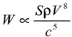
- According to various aspects of the present disclosure, the exit vent flow velocity may be reduced in order to reduce noise.
- In another aspect of the present disclosure, as shown in
Fig. 2-8 , a portion of the mask may be provided with astainless steel mesh 742 that includes plurality ofvent orifices 728 for gas washout. In an example, thestainless steel mesh 742 includeswires 743 that are woven with one another to create the mesh structure with the plurality ofvent orifices 728. The venting or permeability provided by themesh 742 may depend on the wire size and the tightness of the weave, e.g., orifice area may be around 25% of the total area of the mesh and the minimum orifice size may be dictated by the minimum stainless steel wire diameter as the wires weave in and out of one another. In alternative examples, the mesh may be constructed from other woven fabrics or meshed media, e.g., polypropylene, polycarbonate, polyamide (e.g., nylon), polyesters, polytetrafluoroethylene (e.g., Teflon), 3-dimensional spacer fabrics. - Vent arrangements including fine meshing, textiles, fragile construction of materials, and/or very small orifices are potentially prone to blockage from dirt and bio-build-up or damage. Therefore, the user either needs to regularly wash the vents or replace them to ensure that adequate vent flow is maintained for good CO2 washout.
- According to an aspect of the present disclosure, the positive airway pressure device (PAP) device or flow generator may include an alarm to signal the user in the event of reduced vent flow so that the user knows when to replace/wash the vent arrangement. Fail-safe modes are also ways to ensure that the user is cautioned to replace/wash their vents. For instance, if the vent media were assembled to the mask with an adhesive, the adhesive could be CO2-sensitive/H2O-sensitive which would gradually dissolve with a pre-determined exposure to exhaled CO2/humidity. Eventually, the vent media may become loose and may expose a gap (between the vent media and mask) which would still allow for the exhaustion of exhaled gases, however, it may be quite noisy. Another fail-safe mode that is somewhat similar is to ensure that the vent component has a preloaded assembly feature that gradually relaxes (i.e., creeps) with time resulting in a loosely fitting vent that would expose a gap between the vent component and the mask interface to which it is assembled.
- In another aspect of the present disclosure, a hydrophobic coating may be provided on the inside of the vent material, i.e., hydrophobic coating along the vent inlets. The hydrophobicity of the vent inlets will help to prevent the vent orifices from being blocked by humidity.
- In an aspect of the present disclosure, as shown in
Figs. 2-9-1 and 2-9-2 , the mask may include a dome-shapedportion 845 and a cluster offine vent orifices 828 distributed over the dome-shapedportion 845 for gas washout. In the illustrated example, the orifice arrangement includes a central orifice and a plurality of orifices arranged in a circle about the central orifice. As illustrated, theorifices 828 are separated from one another by a distance x and eachorifice 828 has a diameter size d. However, other suitable orifice arrangements are possible. For example, the orifices may be distributed over the dome in other manners, e.g., random, linearly, other patterns, etc. - In an example, Computational Fluid Dynamics (CFD) may be used to model variation in orifice size and orifice separation to achieve an optimum balance of these two parameters in an attempt to mimic the diffusive properties of membranes such as Gore-Tex™.
- In terms of manufacturability, the orifices may be molded out of a sheet of silicone rubber or elastomer and the sheet may be subsequently stretched over a support structure or railing (provided to the mask) structured to curve the sheet into a dome shape. However, the vent arrangement may be constructed in other suitable manners.
- In another aspect of the present disclosure, the mask may include multiple vent orifices with adjacent vent orifices having a different size, e.g., alternating smaller and larger vent orifices. Such arrangement may reduce noise in use.
- The amount of generated vent noise is very sensitive to the difference in velocity between the exit vent flow and the velocity of the air surrounding the exit vent stream (i.e., typically the ambient air, which is relatively still).
- By having variation in the size and length of adjacent vent orifices, differences in adjacent exit vent velocities are created since jet stream velocity is dependent on orifice size and flow path length. This can effectively reduce the velocity gradient between the exhaust streams and the still ambient air.
- In another aspect of the present disclosure, the vent arrangement may include a cluster of vent orifices distributed over a portion of the frame for gas washout. In
Figs. 2-10-1 and 2-10-2 , thevent orifices 928 are arranged within a circular area having a diameter d, and theorifices 928 have different sizes. - In the illustrated example, the cluster includes a central or inner orifice 928(1) having a first diameter d1, a plurality of middle orifices 928(2) (e.g., six orifices) regularly spaced and separated from one another along a circle about the inner orifice 928(1) and each having a second diameter d2 that is larger than diameter d1, and a plurality of outer orifices 928(3) (e.g., eight orifices) regularly spaced and separated from one another along a circle that is concentric with the middle orifices 928(2) and each having a third diameter d3 that is larger than diameter d2.
- Similar to the concept described above in section 2.13, the vent arrangement includes adjacent orifices of different size to reduce noise. Specifically, as shown in
Fig. 2-10-2 , the vent arrangement gradually creates different levels of velocity shrouds going from inside to outside a cluster of vent orifices. As illustrated, the velocity shroud is highest on the inner orifice 928(1) and lowest on the outer orifices 928(3) to help reduce the velocity gradient between the highest velocity, central stream and the slow moving ambient air. However, it should be appreciated that the number of orifices, size, length, spacing, and/or general layout may include a range of different permutations, e.g., non-circular arrangement of orifices. - As noted above with respect to
Fig. 2-8 , a portion of the mask may be provided with a stainless steel mesh that includes plurality of vent orifices for gas washout. In an example, the stainless steel mesh may be heavily coated with a hydrophobic material. If the hydrophobic coating is sufficiently thick, the coating can help to block up the typically large orifice size defined in stainless steel woven meshes such as themesh 742 described above. - In an aspect of the present disclosure, a hydrophobic mesh/fabric such as that described above may be a medical grade filtration mesh with an extremely consistent, fine, orifice size, e.g., mesh and fabric available from Sefar.
- In another aspect of the present disclosure, as shown in
Fig. 2-11 , the mask may include avent orifice 1028 and acap 1050 that covers thevent orifice 1028 to define a small gap or vent passage 1026 that directs gas washout to an outlet remote from the mask, e.g., similar to the slot-orifice vent in ResMed's UltraMirage mask. Thecap 1050 may include anarcuate portion 1051 adjacent the vent outlet. - The thin slot or vent passage 1026 provides for much greater effective area to encourage a long flow path to fully develop flow, thereby reducing the amount of generated vent noise. The effective venting area is just the area of the small orifice at 1028. However, the relatively large vent cap radius, half d1, provides for a long flow path.
- In another aspect of the present disclosure, the orifice size may be selected so that it is both cleanable and quiet. In an example as shown in
Fig. 2-12 , for a mask having a frame thickness of about 1.7 mm, the diameter range between d1 and d2 of the orifice may be between about 0.4 - 0.8 mm. As illustrated, a larger diameter orifice is easier to clean, however the larger the orifice the nosier the orifice. Such orifice size may vary, e.g., depending on frame thickness, desired cleanability and/or quietness, etc. - In another aspect of the present disclosure, the mask vent may be in the form of an insert that is provided to a mask (e.g., snap-fit into position) and defines a plurality of vent orifices. In an example, as shown in
Figs. 2-13-1 to 2-13-3 , theinsert 1160 is constructed of a molded/stamped sheet of plastic (e.g., polypropylene with thickness in the range of about 0.5 - 0.8 mm) having a plurality (e.g.,Figs. 2-5 or3 ) of perforated sections 1162(1), 1162(2), 1162(3) that are folded against each other to produce a three-dimensional matrix of finer, porous vent orifices. - As illustrated, the first section 1162(1) includes a series of slots 1163(1) arranged at a first angle, the second section 1162(2) includes a series of slots 1163(2) arranged at a second angle, and the third section 1162(3) includes a series of slots 1163(3) arranged at a third angle. In the illustrated example, the first angle is about 135° from horizontal, the second angle is about 45° from horizontal (i.e., perpendicular to the first angle), and the third angle is vertical or about 90° from horizontal. However, the slots may be arranged at other varying angles. Also, each of the slots has a similar width. However, the slots may have varying widths, which may vary from slots in other sections.
- The sections 1162(1), 1162(2), 1162(3) are joined to one another by integral hinges 1164 (e.g., reduced width, slotted edges between sections) to facilitate folding. Also, ends of the first and third sections 1162(1), 1162(3) may includes locking snaps or
tabs 1165 structured to retain the insert in its folded configuration. - When in its folded configuration, the slots 1163(1), 1163(2), 1163(3) overlap one another to provide fine, porous vent orifices through the
insert 1160. Theinsert 1160 may be unfolded or opened for cleaning and/or quick drying. -
Figs. 2-14-1 to 2-14-3 illustrate another aspect of avent insert 1260 for a mask. In this example, thevent insert 1260 includes a plurality of grill components 1270(1), 1270(2), 1270(3), 1270(4) that are stacked on top of one another to produce a three-dimensional matrix of finer, porous vent orifices. - As illustrated, the
vent insert 1260 includes acylindrical base 1265 that provides a flange orshoulder 1266 adapted to support the base within an outlet opening in the mask. A grill 1268 (e.g., one or more cross-bars) defining a series of slots is provided to an upper portion of thebase 1265. - Also, the upper portion of the
base 1265 includes anannular rim 1267 adapted to support a plurality of disk-like grill components 1270(1), 1270(2), 1270(3), 1270(4). In the illustrated example, four grill components 1270(1), 1270(2), 1270(3), 1270(4) are provided to thebase 1265. However, more or less grill components may be used, e.g., 1, 2, 3, 4, or more grill components. - Each disk-like grill component 1270(1), 1270(2), 1270(3), 1270(4) includes a
grill 1272 defining a series of slots and anannular rim 1274 adapted to interlock with thebase 1265 and/or other grill components. Specifically, the upper edge of the annular rim includes diametrically opposedprotrusions 1276 and the lower/outer edge of the annular rim includes a series of recesses 1278 (e.g., twelve recesses) regularly spaced and separated from one another. - In use, a first grill component 1270(1) is coupled to the
base 1265 by interlocking selectedrecesses 1278 with the diametrically opposedprotrusions 1269 provided on theannular rim 1267 of thebase 1265. The first grill component 1270(1) may be selectively rotated and interlocked with thebase 1265 in order to adjust the angle of itsgrill 1272 with respect to thegrill 1268 of thebase 1265. - Then, the second grill component 1270(2) may be selectively coupled to the first grill component 1270(1) by interlocking selected
recesses 1278 with the diametrically opposedprotrusions 1276 provided on the first grill component 1270(1). Similarly, the third grill component 1270(3) may be selectively coupled to the second grill component 1270(2), and the forth grill component 1270(4) may be selectively coupled to the third grill component 1270(3). In each coupling, the grill components 1270(1), 1270(2), 1270(3), 1270(4) may be selectively rotated and interlocked in order to adjust the angle of thegrills 1272 with respect to one another. That is, the grill components 1270(1), 1270(2), 1270(3), 1270(4) may be stacked in different configurations to create different arrays of vent orifices through the insert. - In use, as shown in
Fig. 2-14-3 , thegrill 1268 of thebase 1265 and thegrills 1272 of the grill components 1270(1), 1270(2), 1270(3), 1270(4) overlap one another to provide fine, porous vent orifices through theinsert 1260. Theinsert 1260 may be uncoupled or unstacked for cleaning and/or quick drying. -
Figs. 2-15-1 to 2-15-3 illustrate another example of avent insert 1360 for a mask. In this example, thevent insert 1360 includes media 1380 (e.g., (anti-bacterial) filter, membrane, fabric, mesh, or other porous material) to diffuse flow. - As illustrated, the
vent insert 1360 includes acylindrical base 1365 that provides a flange orshoulder 1366 adapted to support the base within an outlet opening in the mask (e.g., base secured to mask by friction-fit, adhesive, etc.). A grill 1368 (e.g., one or more cross-bars) defining a series of slots is provided to a lower portion of thebase 1365. The grill or cross-bar(s) 1368 prevents inadvertent touching of the vent media during mask handling, and thereby minimizes the contamination of the vent media through handling. - The upper portion of the
base 1365 includes anannular rim 1367 adapted to support at least one ormore media 1380, e.g., one or more layers, e.g., two layers. Also, a plurality of snap-fit tabs 1375 (e.g., four snap-fit tabs) extend upwardly from the rim. Thetabs 1375 are adapted to interlock with acover 1385 structured to maintain themedia 1380 within thebase 1365. - The
cover 1385 includes anannular side wall 1386 and a cross-bar 1387. An edge of the side wall includes an engagement flange 1386(1) adapted to engage within a recess 1375(1) provided in each of thetabs 1375 with a snap-fit. The cross-bar 1387 prevents inadvertent touching of the vent media during handling of the mask to minimize contamination of the vent media (e.g., from body oils, hand moisturizers, etc.). - In use, at least one
media 1380 is selected (e.g., (anti-bacterial) filter, membrane, fabric, mesh, or other porous material) and inserted within thebase 1365, and thecover 1385 is snap-fit to thebase 1365 to retain themedia 1380 therein. As shown inFig. 2-15-3 , the vent flow is diffused as it passes through thegrill 1368 andmedia 1380 of theinsert 1360, which reduces noise. Thecover 1385 may be removed to clean and/or replace themedia 1380. - In an example, the
base 1365 andcover 1385 may be molded of a plastic material to define a plastic casing for the at least onemedia 1380. The at least onemedia 1380 may be overmolded or adhered to the casing. In such arrangement, theentire vent insert 1360 may be replaced (i.e., replaceable cartridge), rather than replace the individual media. -
Figs. 2-16-1 to 2-16-3 illustrate another example of avent insert 1460 for a mask. In this example, thevent insert 1460 includes two layers of media 1480(1), 1480(2) (e.g., (anti-bacterial) filter, membrane, fabric, mesh, or other porous material) to diffuse flow. - As illustrated, the
vent insert 1460 includes acylindrical base 1465 that provides a flange orshoulder 1466 adapted to support the base within an outlet opening in the mask. Agrill 1468 defining a series of slots is provided to a lower portion of thebase 1465. Thegrill 1468 prevents inadvertent touching of the vent media during mask handling, and thereby minimizes the contamination of the vent media through handling. - The upper portion of the
base 1465 includes a lower annular rim 1467(1) adapted to support a first media 1480(1) and an upper annular rim 1467(2) adapted to support a second media 1480(2). Also, anengagement flange 1475 extends upwardly from the upper rim and is adapted to engage acover 1485 structured to maintain the first and second media 1480(1), 1480(2) within thebase 1465. - The
cover 1485 includes aring portion 1486 and a cross-bar 1487. An edge of thering portion 1486 is adapted to engage theflange 1475 provided to thebase 1465. The cross-bar 1487 prevents inadvertent touching of the vent media during handling of the mask to minimize contamination of the vent media (e.g., from body oils, hand moisturizers, etc.). - Further, the perimeter of the
base 1465 includes a recessed side wall and a series ofslots 1482 extending through the side wall. A cylindrical band 1483 (e.g., filter or other suitable permeable media) is provided to the recessed side wall and covers theslots 1482. - In use, a first media 1480(1) is selected (e.g., (anti-bacterial) filter, membrane, fabric, mesh, or other porous material) and inserted into the lower rim 1467(1) of the
base 1465, a second media 1480(2) is selected (e.g., (anti-bacterial) filter, membrane, fabric, mesh, or other porous material) and inserted into the upper rim 1467(2) of thebase 1465, and thecover 1485 is engaged with thebase 1465 to retain the media 1480(1), 1480(2) therein. As illustrated, thecover 1485 includes anannular protrusion 1469 adapted to engage an upper surface of the second media 1490(2) to secure the same in position. It should be appreciated that the first and second media may include similar structures (e.g., material, thickness, etc.), or the first and second media may include structures that are different from one another. Also, the first and second media may include different diameters (as illustrated) or the first and second media may include similar diameters (with the base structured to support the same). - As shown in
Fig. 2-16-3 , the vent flow is diffused as it passes through thegrill 1468 and first and second media 1480(1), 1480(2) of theinsert 1460, which reduces noise. In addition, the vent flow may pass through theslots 1482 andband 1483 between the first and second media 1480(1), 1480(2) to diffuse the flow. Thecover 1485 may be removed to clean and/or replace the first and second media 1480(1), 1480(2). Utilizing an arrangement of double layer vent media compared with a single layer of vent media allows the use of more permeable, open-structured weaves. The larger orifices of these more open-weaves are less likely to occlude with debris, humidity and saturation. More open-weaves are also easier to clean. -
Figs. 2-17-1 to 2-17-3 illustrate another example of avent insert 1560 for a mask. In this example, thevent insert 1560 includes pleated media 1580 (e.g., (anti-bacterial) filter, membrane, fabric, mesh, or other porous material) to diffuse flow. - As illustrated, the
vent insert 1560 includes acylindrical base 1565 that provides a flange orshoulder 1566 adapted to support the base within an outlet opening in the mask. Agrill 1568 defining a series of slots is provided to a lower portion of thebase 1565. Thegrill 1568 prevents inadvertent touching of the vent media during mask handling, and thereby minimizes the contamination of the vent media through handling. - The upper portion of the
base 1565 includes anannular rim 1567 adapted to supportmedia 1580 having a plurality of pleats or folds. Also, anengagement flange 1575 extends upwardly from the rim and is adapted to engage acover 1585 structured to maintain themedia 1580 within thebase 1565. - The
cover 1585 includes aring portion 1586 and a cross-bar 1587. The cross-bar 1587 prevents inadvertent touching of the vent media during handling of the mask to minimize contamination of the vent media (e.g., from body oils, hand moisturizers, etc.). The edge of thering portion 1586 includes a recess and adapted to engage theflange 1575 provided to thebase 1565. - In use, a
pleated media 1580 is selected (e.g., (anti-bacterial) filter, membrane, fabric, mesh, or other porous material) and inserted within thebase 1565, and thecover 1585 is engaged with thebase 1565 to retain themedia 1580 therein. - As shown in
Fig. 2-17-3 , the vent flow is diffused as it passes through thegrill 1568 and thepleated media 1580 of theinsert 1560, which reduces noise. Thecover 1585 may be removed to clean and/or replace thepleated media 1580. The use of pleated media allows for a greater area of lower air permeability, venting media to be used whilst still maintaining the footprint within a relatively small area. The lower the air permeability of the venting media, the more effective it is at reducing noise and diffusing air flow as it is much more restrictive to flow. - In examples described above, media (e.g., (anti-bacterial) filter, membrane, fabric, mesh, or other porous material) may be provided to the vent arrangement (e.g., vent insert) to diffuse flow. Media may be selected from a range of materials, properties, and manufacturers.
- For example, exemplary media may be disposable and/or hydrophobically treated and may be in the form of a plastic mesh, stainless steel mesh, 3D spacer fabric, felt, and/or membranes (e.g., PALL, Gore-Tex, GE Energy). Specific examples include PALL BB Filter (hydrophobic), GE Energy ePTFE membrane, Gore-Tex ePTFE membrane, Sefar PP mesh 05-1001-K120, Sefar PP mesh 05-1001-K079, Sefar PP mesh 05-8000-K085, 3D spacer fabric SPC-121, Sefar SS mesh 165/1400, Sefar PET mesh 07-88-K080 double layer, Sefar PET mesh 07-88-K080 double-layer-gap, Sefar PET mesh 07-88-K060 double layer, Sefar NFW-PEPE-384-CS17, Transpor Drylayer woven wicking fabric, reticulated foam, and/or 3M 8710E non-woven.
- Advantages of the plastic mesh include: hydrophobic treatment, small footprint, humidification, biocompatible, and/or simple automated punching and overmolding. Advantages of the stainless steel mesh include high perceived value, robustness, and/or biocompatible. Advantages of the 3D spacer fabric include small footprint and/or humidification. Advantages of the felt include semi-hydrophobic, control of permeability with density, and/or less expensive. Advantages of the membranes include pleating, cost, hydrophobic. "high tech", and/or biocompatible.
- In an example, the media may be constructed of an electrically conductive material that allows a current to pass through the media, e.g., to dry the media during and/or after use and prevent water vapor from clogging the vent openings.
- As noted above, the vent arrangement may be a common component structured for use in multiple interface types. For example,
Figs. 2-18-1 to 2-18-3 illustrate thevent insert 1360 shown inFigs. 2-15-1 to 2-15-3 provided to three different types of interfaces. InFig. 2-18-1 , thevent insert 1360 is attached to themask frame 1624 of a mask. InFig. 2-18-2 , thevent insert 1360 is attached to themask elbow 1627 of a mask. InFig. 2-18-3 , thevent insert 1360 is attached to the end of aframe 1629 for a nasal prong arrangement. The interchangeability of thevent insert 1360 facilitates manufacturing and replacement. - As noted above in
Fig. 1-1 , vent flow for a single large outlet with a relatively short flow path produces relatively high velocity flow. Such high velocity flow is considered a "jet stream", generating large changes in speed directly outside the outlet. Such arrangement generates high jet noise. - Since the noise level is determined by the speed of the jet stream in relation to the speed of the surrounding air, noise production can be greatly reduced by using an extra air stream with a lower speed outside the jet stream as shown in
Fig. 2-19 (i.e., central higher-velocity stream and outer lower-velocity streams. As illustrated, the graduated change in speed across the streams is less than that of a single stream to ambient air.Fig. 2-19 is a schematic of the velocity shrouds described above with respect toFig. 2-10-2 for example. -
Fig. 2-20 illustrates an example of adual flow mouthpiece 1790 for an air compressor. This example illustrates an application of the theory inFig. 2-19 to reduce noise of the jet stream. As illustrated, thedual flow mouthpiece 1790 includes acentral conduit 1792 that provides a fast inner stream and an outerannular conduit 1794 that provides a slow outer stream. Such arrangement produces less noise than a mouthpiece having a single conduit or stream. -
Figs. 2-21-1 to 2-21-4 illustrate anelbow assembly 1845 according to an aspect of the present disclosure. Theelbow assembly 1845 includes a vent arrangement that allows part of the vented gas to move at a slower speed outside a faster central stream to reduce noise. Such vent arrangement may be adapted for use with elbow assemblies described inU.S. Provisional Application No. 60/924,359, filed May 10, 2007 - As shown in
Figs. 2-21-1 to 2-21-4 , theelbow assembly 1845 includes anelbow 1846 and acover 1850 releasably attached to theelbow 1846. Theelbow 1846 includes a first end 1846(1) for releasably engaging with an opening in a mask frame and a second end 1846(2) for releasably engaging with a swivel. Each of the first and second ends 1846(1), 1846(2) include a plurality of resilientflexible arms 1847 adapted to engage the frame/swivel with a snap-fit. - The main body of the
elbow 1846 includes a venting area which includes a plurality ofvent orifices 1828 for gas washout. As best shown inFigs. 2-21-3 and 2-21-4 , eachvent orifice 1828 tapers from a smaller cross-section at the vent inlet to a larger cross-section at the vent outlet. A pair of lugs 1848 (only one being visible inFig. 2-21-1 ) are provided on opposing sides of the venting area. Thelugs 1848 are adapted to engage respective retaining members 1851 (seeFig. 2-21-2 ) provided on an inside surface of thecover 1850. Also, one or more tabs 1849 (seeFig. 2-21-1 ) are provided to the main body of theelbow 1846 to space thecover 1850 away from the outer surface of the main body. In an alternative example, the taper direction of the vent orifices may be reversed, i.e., from larger cross-section at the inlet to smaller cross-section at the outlet. - As shown in
Fig. 2-21-2 , theelbow 1846 includes abaffle 1852 adjacent to where theelbow 1846 is attached to the mask frame. Thebaffle 1852 has a generally U-shape and is arranged to divide the upper arm of the elbow into an air delivery passage and an exhaust passage. - The
cover 1850 includes a venting area which includes a plurality ofvent clusters 1854 for gas washout. Specifically, eachvent cluster 1854 includes a tubular spigot that defines anorifice 1856 that tapers from a larger cross-section at the inlet to a smaller cross-section at the outlet, and a plurality of arcuate shaped orifices 1858 (e.g., 4 orifices) regularly spaced and separated from one another along a circle about the spigot and each having a cross-section that tapers from a larger cross-section at the inlet to a smaller cross-section at the outlet. In an alternative example, the taper direction of the orifices may be reversed, i.e., from smaller cross-section at the inlet to larger cross-section at the outlet. - In the connected position, the venting area of the
cover 1850 is aligned with the venting area of theelbow 1846 to define vent flows with a faster inner stream and a slower outer stream as shown inFig. 2-21-3 . Specifically, eachvent cluster 1854 of thecover 1850 is aligned with arespective orifice 1828 of theelbow 1846 such that the spigot of eachvent cluster 1854 extends partially within therespective orifice 1828 of theelbow 1846. - In use, vent flow passes through the
orifices 1828 of theelbow 1846 and intorespective vent clusters 1854 of thecover 1850. As shown inFig. 2-21-3 , the flow passing through theorifice 1856 of the spigot is faster than the flow passing through theorifices 1858 outside the spigot. The extra, slower outer stream can reduce vent noise in use. - Such arrangement also allows pins with a thickness of 0.7 mm or less to be used to mold very small holes, i.e., the
arcuate orifices 1858 around thecentral orifice 1856. In known embodiments, normal molding pins having a diameter of less than 0.7 mm are not particularly robust for use in tooling for molds. - In an example of the vent arrangement, as shown in
Fig. 2-21-4 , D1 may be about 1.76 mm, D2 may be about 0.7 mm, D3 may be about 0.3 mm, D4 may be about 1.13 mm, D5 may be about 1.6 mm, D6 may be about 2.6 mm, D7 may be about 2.5 mm, D8 may be about 1.5 mm, and D9 may be about 2 mm. Although specific dimensions and ranges of the vent arrangement are indicated, it is to be understood that these dimensions and ranges are merely exemplary and other dimensions and ranges are possible depending on application. For example, the exemplary dimensions may vary by 10-20% or more or less depending on application. -
Figs. 2-22-1 and 2-22-2 illustrate avent arrangement 2000 according to another aspect of the present disclosure. In this example, thevent arrangement 2000 includes one ormore protrusions 2002 provided to aventing area 2004 of the mask, and one ormore vent openings 2006 are provided in side walls of eachprotrusion 2002 to vent washout gas. In addition, one ormore vent openings 2008 may be provided in the venting area adjacent theprotrusions 2002 to vent washout gas. In use, washout gas from thevent openings 2006 in theprotrusions 2002 and washout gas from thevent openings 2008 in the adjacent venting area are directed into one another to diffuse the air flow, which results in more diffused venting. Alternatively, the adjacent streams may also be slightly offset to avoid direct collision of the streams to minimize turbulent noise yet still provide some degree of diffusion. - In the illustrated example, the
venting area 2004 provides abase wall 2005 and the plurality ofprotrusions 2002 extend outwardly from thebase wall 2005. As illustrated, eachprotrusion 2002 is in the form of a truncated pyramid, and avent opening 2006 is provided through each side wall of the pyramid, i.e., fourvent openings 2006 per pyramid. However, it should be appreciated that any suitable number of openings may be provided to each pyramid, e.g., multiple openings in each side wall, opening in only selected side walls, opening in at least one side wall, etc. Also, in the illustrated example, eachopening 2006 has a generally trapezoidal shape, e.g., height of about 0.2-0.6 mm (e.g., 0.4 mm). However, the openings may have other suitable shapes, sizes, and/or arrangement, e.g., circular, tapered along its length, etc. - As shown in
Fig. 2-22-1 , theprotrusions 2002 are arranged corner to corner in a spaced-apart, grid-like manner. Such arrangement defines multiple venting areas between theprotrusions 2002 in whichrespective vent openings 2008 are provided. However, other suitable arrangements of the protrusions are possible, e.g., random, circular, rows, columns, etc. In addition, it should be appreciated that more than oneopening 2008 may be provided in each venting area defined betweenprotrusions 2002. Also,openings 2008 may simply not be provided. - In the illustrated example, each
opening 2008 has a generally circular shape. However, theopenings 2008 may have other suitable shapes, sizes, and/or arrangement, e.g., non-circular, tapered along its length, etc. - The
protrusions 2002 are structured to increase the surface area available for venting so more vent openings may be provided over a venting area of the mask. For example, in the illustrated example, theprotrusion 2002 provides fourvent openings 2006 in a similar area as eachvent 2008. - In use, the
vent openings 2006 in theprotrusions 2002 and thevent openings 2008 in thebase wall 2005 are arranged so that washout gas is directed in different directions, into one another and/or slightly offset from one another to create diffuse air flow, e.g., seeFig. 2-22-1 . - It should be appreciated that the protrusions may have other suitable shapes or arrangements. For example, the protrusions may be star-shaped, crescent-shaped, alphanumerically shaped, logo-shaped, hexagonal, octagonal, etc. That is, the protrusions may have any suitable shape with vent openings arranged to deliver exhaust gases in a direction that is not parallel to adjacent vent orifices. Also, as shown in
Figs. 2-22-3 and2-22-4 , the lower edge of thevent openings 2006 may align with thebase wall 2005, rather than be spaced upwardly from thebase wall 2005 as inFigs. 2-22-1 and 2-22-2 . Additionally, the inner base wall or interior surface ofprotrusion 2002 may be shaped rather than planar (as shown inFigs. 2-22-2 and2-22-4 ), for example angular or rounded. This arrangement may direct the air stream out ofvent openings 2006 in a smoother pathway, thereby reducing turbulent flow and thus noise. -
Fig. 2-22-5 is a schematic view of a mold for molding the protrusions ofFigs. 2-22-3 and2-22-4 . As illustrated, upper and lower molds UM, LM cooperate to define the top of the protrusions, the base wall, and the vent openings therebetween. - In another example, as shown in
Fig. 2-23 , each of the protrusions may have an inverted configuration, e.g., truncated pyramid-shaped recess that extends inwardly from thebase wall 2005 and into the breathing cavity. In such arrangement, avent opening 2007 may be provided in the bottom wall of each truncated pyramid-shaped recess rather than thebase wall 2005 to create diffuse flow. - In another example, as shown in
Fig. 2-24 , each protrusion may have a dome-shape withvent openings 2006 provided along the dome. - In yet another example, as shown in
Fig. 2-25 , each protrusion may be in the form of an elongated three-dimensional trapezoid withvent openings 2006 along side walls thereof. As illustrated, the 3-D trapezoids may be spaced apart to define venting areas therebetween in which ventopenings 2008 are provided. - In an example, the protrusion may be provided as a separate component from the mask that is adapted to be attached or retrofit to the mask including one or more vent openings. That is, the protrusion may be secured in position (e.g., glued, snap-fit, etc.) over a selected vent opening to cover the vent opening and provide diffused vent flow as gas passes therethrough in use.
-
Fig. 2-26 illustrates avent arrangement 2100 according to another aspect of the present disclosure. In this example, thevent arrangement 2100 is structured to be connected between the mask and the air delivery conduit. As illustrated, thevent arrangement 2100 includes a plurality ofdisks 2195 adapted to be stacked on top of one another. A plurality of the disks 2195 (e.g., every disk in the stack, every other disk in the stack, etc.) include vent openings 2197 (e.g., curved recesses) that create passages for diffused vent flow. A longer length of the stacked disks may create more diffuse vent flow. - In an example, the disks may be coupled to one another (e.g., slinky-like arrangement) to create a one-piece structure, e.g., to facilitate cleaning and reduce the risk of losing small parts.
-
Fig. 3 provides a chart illustrating sound power for vent media described above. As illustrated, at 10 cmH2O, the sound power for vent media described above may range from about 22 dBA to about 45 dBA for a flow rate of about 6-57 L/min, and at 20 cmH2O, the sound power may range from about 28-35 dBA for a flow rate of about 23-42 L/min. The standard vent can be, for example, the vent arrangement shown inFig. 4-1A . - The vent media may be selected based on sound requirements, preferences, etc. For example, in an example, the vent may be quieter than about 30 dBA. In another example, the vent may be quieter than about 25 dBA. The sound power for the vent media may be dependent on the coarseness of the fibers in each vent media, the size of the holes in the vent media, and/or the flow path through the vent media.
- In an example, the fibers in the vent media may not be coarse so as to avoid turbulent flow. For example, ePTFE membrane may have flaws and variations throughout the membrane and therefore may cause higher noise levels particularly at higher flow rates.
- In an example, the size of the holes in the vent media may be small, for example, the stainless steel meshes may have small vent holes that emit an acceptable level of noise.
- In an example, the flow path through the vent media may be generally long and direct, forming for example a continuous tunnel. For example, the flow path through the PP mesh may be more direct (due to the arrangement of fibers) than that through the reticulated foam or woven wicking fabric thereby reducing the noise emitted from the PP mesh than the foam.
-
Fig. 4-1A to 4-7D illustrate vent arrangements according to various aspects of the present disclosure. In these aspects, the mask vent is in the form of a vent cap structured to be releasably attached to an opening or venting area of the mask. The vent cover includes a plurality of vent holes constructed and arranged to diffuse airflow leaving the mask in use. -
Figs. 4-1A to 4-1C illustrate vent caps according to alternative aspects of the present disclosureFig. 4-1A illustrates avent cap 2200 includingmultiple vent holes 2230 arranged on a base wall to direct airflow away from the patient's face in use.Fig. 4-1B illustrates avent cap 2300 for a vent arrangement according to an embodiment of the present invention, thevent cap 2300 includingmultiple vent holes 2330 arranged on an annular side wall to provide diffuse airflow that is directed away from the patient's face as well as the bed partner. The angle of the diffused airflow can be tuned by altering the dimensions of the vent cap.Fig. 4-1C illustrates avent cap 2400 including media 2430 (e.g., textile, filter, membrane, fabric, mesh, or other porous material or means of ventilation) structured to diffuse airflow from the mask. - In each vent cap aspects, there may be any suitable number of holes distributed around the vent cap. Each hole may have any suitable shape, e.g., generally round, square, tapered along its length, etc. Also, the holes may be uniform or varying in size and/or shape. In an embodiment, each hole may be no smaller than about 0.00-0.08 mm in diameter. Preferably, each hole may be no smaller than 0.6-0.8 mm (e.g., 0.7 mm) in diameter. Smaller holes may be preferable as they direct air flows in such a way that they become more fully developed flows. In an alternative example, the vent cap may include a venting area adapted to be aligned with a venting area of the mask (e.g., elbow) when assembled together to define "full" vent passages, e.g., similar to the arrangement shown in
Figs. 2-21-1 to 2-21-4 described above. - In an example, the vent cap may be made from a polymer, such as polypropylene or polycarbonate. However, other suitable materials are possible. Also, the vent cap may be constructed and arranged to be relatively durable, or the vent cap may be constructed and arranged to be less durable, replaceable, and/or disposable.
- The
vent cap 2300 for a vent arrangement according to an embodiment of the present invention now be described in greater detail. As shown inFigs. 4-2A to 4-2C and4-3A to 4-3C , thevent cap 2300 includes abase wall 2335 and adome 2340 that extends upwardly from thebase wall 2335 above the horizontal surface of thebase wall 2335. As illustrated, themultiple vent holes 2330 are arranged on an annular side wall of thedome 2340. - The
dome 2340 may have a generally hemispherical, trapezoidal, square, or other desired shape. Preferably, thedome 2340 has a low profile, e.g., raised 1-3 mm (e.g., 2 mm) from the horizontal surface of the base wall. This arrangement helps to direct air flow in long, thin paths so as to maintain more fully developed and/or laminar flow. Also, the "domed" vent cap directs exhaust flow up and out from the mask, i.e., "domed" vent cap alternates the direction of exhaust flow from a first incoming direction d1 to a second outgoing direction d2 that is sloped or angled with respect to the first direction d1, e.g., substantially perpendicular, as shown inFig. 4-3B . In addition, the vent cap constitutes an exhaust divider as the vent holes are arranged to divide the exhaust flow in different directions as it exits the vent cap. In the illustrated embodiment, the vent holes are arranged radially along the annular side wall of thedome 2340 to radially divide the exhaust flow in 360°. However, it should be appreciated that the vent holes may be arranged in other suitable manners radially along the annular side wall of the dome as long as they radially divide exhaust flow over one or more portions totaling at least 90°, e.g., a portion of the circumference from 90° up to 360° (e.g., 270°, 180°, 90°, or anywhere in between), selected arcs or portions of the circumference (e.g., selected portions on opposite sides of the dome). Alternative vent hole arrangements on the dome may be selected to direct exhaust gas in certain directions, e.g., away from the patient's face or bed partner. Also, as shown inFig. 4-3B , the vent holes may be configured to direct exhaust gas at an angle with respect to horizontal, e.g., vent holes may direct exhaust in direction d2 or at angles α1, α2 with respect to d2 (e.g., α1, α2 about 0-20°). Thedome 2340 may be any suitable size, but should not be wider than the base wall. The outer surface of thedome 2340 may have a smooth finish, e.g., the vent holes 2330 are not raised or sunken into the outer surface of thedome 2340. However, in an alternative embodiment, theholes 2330 may be raised or sunken into the outer surface of thedome 2340. - In the illustrated embodiment, each of the vent caps is structured to be releasably attached to the mask by means of a bayonet connection. Attachment of the
vent cap 2300 to anelbow 2390 of the mask will now be described in greater detail. However, it should be appreciated that the vent cap may be releasably attached to another portion of the mask in a similar manner, e.g., mask frame. Also, it should be appreciated that the vent cap may be attached to the mask in other suitable manners, e.g., snap fit, ultrasonically welded (in which case, it would not be a releasable component), interference fit, sliding fit, permanently machined into the mask, etc. - As shown in
Figs. 4-2A to 4-2C and4-3A to 4-3C , thevent cap 2300 includes outer and inner side walls (e.g., seeFig. 4-2B ) 2352, 2354 that extend downwardly from thebase wall 2335 and define achannel 2356 therebetween. Two diametricallyopposed projections 2360 extend radially inwardly from theouter side wall 2352. In addition, thevent cap 2300 includes awindow 2358 adjacent eachprojection 2360 that allows the user to visually recognize when thevent cap 2300 is in a locked position as described below. - As shown in
Figs. 4-5A to 4-5B and4-7D , theelbow 2390 includes anopening 2392 for gas washout. Anannular lip 2394 surrounds theopening 2392 and one or more ribs 2396 (e.g., two diametrically opposed ribs) extend radially outwardly from thelip 2394. In the illustrated embodiment, eachrib 2396 is generally L-shaped including a first leg 2396(1) and a second leg 2396(2). The second leg 2396(2) is a bayonet "stop" which prevents the vent cap from over-turning and subsequently disengaging. The second leg 2396(2) also offers feedback to the user that they have reached the "end" and the vent cap is properly locked. -
Figs. 4-6A to 4-6B and4-7A to 4-7C illustrate attachment of thevent cap 2300 to theelbow 2390.Figs. 4-6A to 4-6B illustrate thevent cap 2300 in an unlocked position with thevent cap 2300 resting on theelbow lip 2394, i.e.,channel 2356 receiveselbow lip 2394 andribs 2396 therebetween. As illustrated, theouter side wall 2352 of thevent cap 2300 overhangs theelbow lip 2394 such that theprojections 2360 are circumferentially spaced from theelbow ribs 2396. - The
vent cap 2300 is rotatable with respect to theelbow 2390 to move thevent cap 2300 to a locked position as shown inFigs. 4-7A to 4-7C . As illustrated, thevent cap 2300 is rotated to position theprojections 2360 underneath respective first legs 2396(1) of theribs 2396, and thereby axially lock thevent cap 2300 in position on theelbow 2390. The second legs 2396(2) of theribs 2396 prevent further rotation of thevent cap 2300 with respect to theelbow 2390, i.e., further rotation causesprojections 2360 to engage respective second legs 2396(2). As shown inFig. 4-7B , thewindow 2358 in thevent cap 2300 allows the user to visually recognize when the first legs 2396(1) of theribs 2396 are aligned with theprojections 2360 and hence locked. - The bayonet connection provides a relatively simple and intuitive arrangement to use. It also minimizes leak from the vent cap since the connection is radial and does not require an interference to lock the vent cap in position, e.g., like a clip-on vent cover.
- In an embodiment, vent cap will diffuse air so that the air flow is undetectable by a person at a distance of less than about 500 mm from the vent, e.g., less than 200 mm, less than 100 mm, less than 50 mm, less than 30 mm.
- In an embodiment, vent cap will produce less than about 40 dBA sound power at 10 cmH2O tested according to ISO3744, e.g., less than 30 dBA, less than 25 dBA, less than 20 dBA.
- In
Figs. 4-1A to 4-3B , the vent cap has a generally circular shape. However, the vent cap may have other suitable shapes that allow a bayonet connection or other connection mechanism. For example, as shown inFigs. 4-4A and 4-4B , thevent cap 2300 may include anextended edge 2380 that protrudes outwardly from thebase wall 2335. - The ideal vent will be quiet and diffuse. Noise can be minimized by promoting low velocity, fully developed, laminar flow from the vent. Diffuse flow can be achieved by releasing the air flow over a larger area. Vent arrangements are described below that are structured to minimize noise and diffuse flow from the vent though a combination of features.
- Additionally, the vent will be able to maintain flow under saturated or humidified conditions, minimize CO2 re-breathing, be manufacturable, be cleanable or disposable, and biocompatible.
- In an aspect of the present disclosure, air flow that is exiting a mask system will be directed through a vent that is quiet and diffuse. In a preferred form, noise from the vent will be less than about 30-40 dBA, e.g., less than 35 dBA. In an example, the vent may be considered "super quiet" when noise is less than about 30 dBA, e.g., about 20-25 dBA.
- It is to be understood that the following examples include features that may be incorporated into a mask system individually or in combination.
- In an aspect of the present disclosure, a
baffle 2500 may be provided between amask 2520 and anelbow 2540 as schematically shown inFig. 5-1 . Thebaffle 2500 may be positioned between theelbow 2540 and a frame or cushion of themask 2520 where air is typically vented from themask 2520. As illustrated, thebaffle 2500 is designed to force air exiting themask 2520 to flow through a narrow pathway. - Preferably, as shown in solid lines in the diagram of
Fig. 5-2 , the baffle will be wide so that the air will flow through a longer pathway (as compared to a narrow baffle in which the pathway is shorter). Such a longer pathway encourages low velocity, fully developed, laminar flow. - In the illustrated example, the baffle is generally circular. However, the baffle may have any suitable shape that closely matches the geometry of the elbow to frame or elbow to cushion connection, e.g., elliptical. In a preferred example, the baffle will be relatively thin to minimize the weight of the mask system. Also, the baffle may not form a completely closed shape, e.g., the baffle may be hemispherical. This arrangement may allow for passage of another apparatus (e.g., anti-asphyxia valve (AAV)) or easier insertion and removal of the baffle.
- In an example, as shown in
Figs. 5-3-1 and 5-3-2 , thebaffle 2500 may have undulations orcurves 2502 to force the air to flow over a larger area before exiting the mask system. This will slow the flow of the air producing low velocity, fully developed, laminar flow. - In one form, the baffle may form a part of the elbow. However, the baffle may be a separate part that may be retrofitted to an elbow. If retrofitted, the baffle may be held in place by any suitable means, e.g., interference fit, push fit, adhesive, etc. In the case where the baffle is to be interference or push fit into the elbow, a lip may be provided to the baffle to enhance sealing.
- In another example, as shown in
Figs. 5-3-1 and 5-3-2 and schematically shown inFig. 5-4 , the baffle may be attached by a bayonet connection. In the illustrated example, thebaffle 2500 includes anannular side wall 2510 with one or moremale connectors 2512 provided to an exterior surface of theannular side wall 2510. Theelbow 2540 includes anannular side wall 2542 with a corresponding number of female connectors 2544 (i.e., L-shaped female connectors) provided to an interior surface of theannular side wall 2542. In use, themale connectors 2512 are received in the first leg 2544(1) of respectivefemale connectors 2544, and then thebaffle 2500 andelbow 2540 are rotated relative to one another to slide themale connectors 2512 into the second leg 2544(2) of respectivefemale connectors 2544. - However, it should be appreciated that other suitable arrangements of the bayonet connection may be provided. For example, the baffle may include female connectors for attachment with male connectors on the elbow. Also, the bayonet connection may be positioned on the annular side walls of the baffle and elbow (as shown in
Figs. 5-3-1, 5-3-2 , and5-4 ), or the bayonet connection may be positioned on the mating surfaces of the baffle and elbow (e.g., seeFig. 5-5 ). - In the illustrated example, the
elbow 2540 includesmultiple vent holes 2545 arranged on an annular side wall so that theelbow 2540 and baffle 2550 are arranged to force washout gas generally parallel to the user's face in use. Typically vents are positioned so that vent flow from the mask system is perpendicular to the user's face and may possibly jet vent flow onto the bed partner or other interferences such as bedding. Jetting increases noise and discomfort for the bed partner. Vented gas traveling parallel to the user's face tends to avoid these problems by "spreading" the vent flow radially over a larger area rather than concentrating it all in a small region. That is, the vent flow in this arrangement is akin to a distributed load rather than a concentrated load, should it meet with an obstruction in its path. - In one form, the
air path 2560 created by the elbow and the baffle will be about 0.01 to 5 mm, e.g., 1 mm. - In another form, the
baffle 2500 may not be anchored in one position. For example, thebaffle 2500 may be able to rotate within theelbow 2540. - In another form, a series of baffles could be used to force air flow out of multiple air paths. For example, 2, 3, 4, or more baffles may be stacked and placed between the elbow and the mask.
- In one form, the baffle may be about 1-30 mm wide (radially), e.g., 10 mm wide (radially).
- In an example, the baffle may be constructed of a hard plastic, e.g., such as polycarbonate. Alternatively, the baffle may be constructed from softer materials to absorb more of the sound, e.g., low durometer silicone. However, other suitable materials are possible.
- In an alternative example, as shown in
Figs. 5-6-1 and 5-6-2 , a single baffle may be used that is coiled to form multiple air paths.Fig. 5-6-1 shows the coil-type baffle 2600 in its uncoiled or uncompressed position, andFig. 5-6-2 shows the coil-type baffle 2600 in its coiled or compressed position between amask 2620 andelbow 2640. As illustrated, the coils cooperate to form multiple air paths along its length. In an example, one or more grooves may be provided in each coil to define air paths across the coil. Such arrangement provides a "stack" of vent rings integrally formed as a one-piece structure. - In an aspects of the present disclosure, tracks or guides may be provided to a vent hole that are structured to force washout gas to flow in long, narrow passages as it exits the mask system.
- For example,
Figs. 5-7-1 and 5-7-2 illustrate anelbow 2740 includingmultiple vent holes 2745 and spaced-apart raisedtracks 2747 proximate eachvent hole 2745 along the inner surface of the elbow 2740 (i.e., the side of the elbow that is subjected to the pressurized air flow). In the illustrated example, thetracks 2747 are generally rectangular. However, the tracks may have other suitable shapes to direct washout gas, e.g., elliptical. In an example, the "track" arrangement may also incorporate the use of an annular baffle as shown inFigs. 5-3-1 and 5-3-2 . - In an alternative example, the tracks may extend into the inner surface of the
elbow 2740. In such example, the tracks would resemble indents or recesses. In use, the indented tracks will draw air flow into them and create a long, narrow flow path. - In another form, the tracks may be uniform in length. Alternatively, the tracks may vary in length. In an example, the tracks will be longer than about 2 mm, e.g., 4 mm.
- In an example, each
vent hole 2745 will have one or more tracks leading to the opening of the hole, e.g., two tracks per vent hole as shown inFig. 5-7-2 . If there is more than one track for each vent hole, the track may be separated by any suitable amount, e.g., more than about 0.1 mm. - In an example, the tracks may be molded or otherwise formed into the elbow. Alternatively, the tracks may be provided in a separate component (e.g., molded into separate component) and retrofitted to the elbow.
- In another example, two or more tracks may join together or otherwise cooperate about a vent hole to form a tube (or at least a portion of a tube). This tube may have a circular cross section, or any other desired cross section, e.g., square. Similar to the tracks, the tube will direct air flow down a long, narrow pathway to form low velocity, fully developed, laminar flow.
- In an aspect of the present disclosure, a baffle with tracks may be provided to an elbow.
- For example,
Fig. 5-8-1 illustrates abaffle 2800 including a plurality oftracks 2802. As illustrated, thebaffle 2800 includes a ring-like structure with eachtrack 2802 extending from an inner radius of the baffle to an outer radius of the baffle. - In the illustrated example, groups of
tracks 2802 are placed about the baffle. However, the tracks may be arranged in other suitable manners, e.g., continuous around the baffle, randomly arranged. - In the illustrated example, each
track 2802 extends into the surface of the baffle like an indent or recess. Alternatively, each track may be raised from the surface of the baffle. - In the illustrated example, each
track 2802 may be curved from the inner radius of the baffle to the outer radius of the baffle. This arrangement maximizes the length of the tracks so that the air travels a longer distance and loses velocity. However, each track may have other suitable shape along its length, e.g., straight line or coiled extending from the inner radius to the outer radius of the baffle. - As shown in
Figs. 5-8-1 and 5-8-2 , thetracks 2802 are provided to one side of thebaffle 2800. However, thetracks 2802 may be provided to both sides of the baffle (e.g., seeFig. 5-8-3 ). -
Fig. 5-8-2 and 5-8-3 show thebaffle 2800 provided to anelbow 2840. As illustrated, theelbow 2840 includes one ormore windows 2870 about its circumference adapted to receive thebaffle 2800. Specifically, thebaffle 2800 extends through thewindows 2870 and includescutouts 2804 to receiveelbow wall portions 2872 adjacent thewindows 2870. Also, thebaffle 2800 is open ended (e.g., C-shaped) to allow thebaffle 2800 to deform slightly during assembly/disassembly to theelbow 2840, e.g., spring like a circlip. - In an example, the
baffle 2800 with tracks on one side may reduce noise from the vent by at least 10 dBA when compared to other conventional masks (e.g., ResMed's Mirage Micro). In terms of human hearing, a 10 dBA reduction in noise corresponds to half the amount of noise previously emitted. A vent cap (as described above in section 4.1) may reduce noise from the vent by at least 3 dBA when compared to other conventional masks. A 5 dBA reduction in noise is clearly noticeable when compared to the noise previously emitted. A 3 dBA reduction in noise is just noticeable when compared to the noise previously emitted. Therefore, the baffle is highly effective in terms of maximizing noise reduction from the vent and diffusing air flow from the vent. -
Figs. 5-9-1 to 5-9-6 illustrate a baffle orvent ring 3100 for anelbow 3140 according to another aspect of the present disclosure As illustrated, thevent ring 3100 has an open-ended C-shapedmain body 3101 with L-shapedfinger tabs 3103 adjacent the open end (seeFig. 5-9-2 ). Themain body 3101 includes a plurality of radially arched tracks orgrooves 3102 on one or both sides thereof. Thegrooves 3102 extend from an inner radius of the vent ring to an outer radius of the vent ring. - In the illustrated example, each groove is open-ended (e.g., U-shaped, V-shaped, semi-circular shaped, etc.) and tapers along its length from the inner radius to the outer radius of the vent ring. In addition, each groove may be radially arched or curved along its length. However, it should be appreciated that each groove may include other suitable arrangements, e.g., same width along its length, zig-zag or other tortuous path along its length, different size, different depth, extend at different angle along main body (e.g., longest path from inner radius to outer radius of vent ring), etc.
- Similar to the
baffle 2800 described above, thevent ring 3100 is deformable (e.g., like a c-clip or circlip) to assemble/disassemble to theelbow 3140. As best shown inFig. 5-9-4 , theelbow 3140 includes aslot 3142 adapted to receive and support thevent ring 3100 within theelbow 3140. Specifically, theslot 3142 provides an entry/exit window 3143 to receive thevent ring 3100, upper andlower flanges vent ring 3100 within the elbow, andwindows 3146 along with entry/exit window 3143 that allow gas washout across thevent ring 3100, and supportingbeams 3148 to maintain and align thevent ring 3100 within theelbow 3140. - To assemble the
vent ring 3100 to theelbow 3140, the user's fingers may be placed in the gaps defined by thefinger tabs 3103 of thevent ring 3100 so as facilitate gripping and squeezing thefinger tabs 3103 towards one another, which distorts or deforms the generally round vent ring into an oval shape (seeFig. 5-9-3 ). Since the width of the distortedvent ring 3103 is now less than a width of the entry/exit window 3143 of theelbow 3140, thevent ring 3100 may be slid through the entry/exit window 3103 and into the elbow 3140 (seeFig. 5-9-4 ). When thefinger tabs 3103 are released, thevent ring 3100 resiliently springs back into shape. Thevent ring 3100 is held in place by an interference fit, where the width of thevent ring 3100 is substantially the same as that of the entry/exit window 3143. In addition, thevent ring 3100 includescutouts 3104 to receive supportingbeams 3148 of the elbow 3140 (seeFigs. 5-9-1 and 5-9-5 ). - Due to forces applied to the
vent ring 3100 for insertion and removal from theelbow 3140, thevent ring 3100 may be made from a substantially rigid or semi-rigid material. Also, theelbow 3140 providesflanges vent ring 3100 to support thevent ring 3100 when it is loaded (e.g., pressurized gas flow), thereby preventing bowing of thevent ring 3100 and thus leak (seeFig. 5-9-6 ). - In use, the grooved vent ring combines with the elbow to define vent orifices, i.e., each vent orifice defined by a part of the vent ring (the groove) and a part of the elbow (upper and/or lower flange). Thus, vented gas escapes along the one or more tracks or grooves between an outer surface of the elbow and the vent ring.
-
Figs. 5-10-1 to 5-10-3 illustrate avent ring 3200 according to another aspect of the present disclosure. In this example, thevent ring 3200 includes a hinge or movable joint 3290 and alocking mechanism 3292 diametrically opposed from thehinge 3290. When thelocking mechanism 3292 is unlocked, thehinge 3290 allows thevent ring 3200 to pivot open and be wrapped around theslot 3142 in the elbow 3140 (seeFig. 5-10-2 ). In the illustrated example, thelocking mechanism 3292 includes a pin and groove arrangement wherein the pin 3292(1) and groove 3292(2) can be pushed together and interlocked (seeFig. 5-10-1 ) to close the arms of thevent ring 3200 around the slot. The groove 3292(2) may be provided to afinger tab 3293 with anarched protrusion 3294 to facilitate grip. Also, as illustrated, thehinge 3290 is provided by a thinned region of the vent ring 3200 (e.g.,cutout 3204 and slot 3291). Thevent ring 3200 should be somewhat flexible to allow thevent ring 3200 to be deformed (hoop stress) into an unlocked or open position for assembly to theelbow 3140. - Similar to the above, the
vent ring 3200 includes a plurality of radially arched tracks orgrooves 3202 on one or both sides thereof. Whengrooves 3202 are provided on both sides, it is preferable to have thegrooves 3202 extending in opposite directions on opposing top and bottom sides so that air streams are exhausted in opposite directions (seeFig. 5-10-3 ), which provides more diffuse exhaust. -
Figs. 5-11-1 and 5-11-2 illustrate avent ring 3300 andelbow 3340 according to another aspect of the present disclosure. In this example, thevent ring 3300 is soft and flexible and includes a closed, o-ring shape so that thevent ring 3300 can be stretched or wrapped around theelbow 3340. Afinger tab 3303 is provided to thevent ring 3300 to facilitate assembly/disassembly to theelbow 3340. - The
elbow 3340 includes aslot 3342 around its perimeter to receive thevent ring 3300. The bottom wall of theslot 3342 includesopenings 3346 for gas washout and each side wall of the slot 3342 (adjacent each opening 3346) includes a plurality of tracks orgrooves 3302. Thus, no grooves are provided on thevent ring 3300, rather thegrooves 3302 are provided on theelbow 3340. In use, thevent ring 3300 forms a seal with theelbow 3340 so that air can only exhaust between thevent ring 3300 and thegrooves 3302 on theelbow 3340. Also, the soft andflexible vent ring 3300 may dampen sound in use. -
Figs. 5-12-1 and 5-12-2 illustrate avent ring 3400 andelbow 3440 according to another aspect of the present disclosure. This example is similar to the example ofFigs. 5-11-1 and 5-11-2 ; in contrast,grooves 3402 are provided on thevent ring 3400, and no grooves are provided on the elbow 3440 (e.g. smooth surface on side walls of the slot 3442). This arrangement may be easier to manufacture. - As illustrated, the
vent ring 3400 includes a plurality of tracks orgrooves 3402 along the entire perimeter of thevent ring 3400. This arrangement provides 360° vent flow which may provide more diffuse exhaust. In an example, a section of thevent ring 3400 may not have grooves, and this section could be aligned with the patient's eyes so that air flow does not irritate the patient's eyes in use. -
Figs. 6-1 to 6-7 illustrate anelbow 3040 including a vent arrangement according to another embodiment of the present invention. In this embodiment, the vent arrangement is in the form of a diffusedvent cap 3000 that is integrally formed in one-piece with theelbow 3040. This arrangement provides a single piece elbow with no removable parts, e.g., so patients do not have to disassemble the elbow for cleaning. In alternative embodiments, the vent cap may be integrally formed in one piece with other portions of the mask, e.g., mask frame, associated conduit, etc. - As illustrated, the
elbow 3040 includes a first end 3040(1) for releasably engaging with an opening in a mask frame and a second end 3040(2) for releasably engaging with a swivel. In the illustrated embodiment, the first end 3040(1) includes opposingribs 3046 adapted to engage the mask frame with a snap-fit. The first end 3040(1) may also have along sealing surface 3041 adapted to interface with the mask frame, whereby such a long sealing surface promotes better sealing thereby reducing leak between the elbow and mask frame. Also, the sealingsurface 3041 may be frosted or textured to prevent noise (for example squeak) created by the friction of two moving parts. The first end 3040(1) may also have a stepped arrangement whereby sealingsurface 3041 is wider than steppedsurface 3042. This may allow for easier disassembly of the elbow from the mask frame. Additionally, scallops or cutouts 3043 may be provided to steppedsurface 3042 to allow the steppedsurface 3042 to flex inwards thereby enabling disassembly of the elbow from the mask frame. The second end 3040(2) includes a plurality of resilientflexible arms 3047 adapted to engage the swivel with a snap-fit. However, the first and second ends 3040(1), 3040(2) may include other suitable structures for engaging the frame/swivel. - The main body of the
elbow 3040 includes avent cap 3000 integrally formed in one-piece therewith. Similar to thevent cap 2300 described above, thevent cap 3000 includes abase wall 3035, adome 3040 extending upwardly from thebase wall 3035, andmultiple vent holes 3030 arranged on an annular side wall of thedome 3040 to provide diffuse airflow that is directed away from the patient's face as well as the bed partner. The angle of the diffused airflow can be tuned by altering the dimensions of the vent cap. The diffused airflow provides venting over a larger area to avoid jetting and may also reduce noise. - As shown in
Figs. 6-2 and6-4 , theelbow 3040 includes abaffle 3052 adjacent to where theelbow 3040 is attached to the mask frame. Thebaffle 3052 has a generally U-shape and is arranged to divide the upper arm of the elbow into an air delivery passage and an exhaust passage, e.g., to enhance CO2 washout. In the illustrated embodiment, thebaffle 3052 is integrally formed with theelbow 3040. However, in an alternative embodiment, the baffle may be retrofit to the elbow.Gaps 3053 are provided on either side of thebaffle 3052 from the inner surfaces of first end 3040(1) to allow steppedsurface 3042 to freely flex inwards when assembled and disassembled to the mask frame. -
Figs. 7-1 to 7-3 illustrate a plug-type vent 3500 andframe 3540 according to another aspect of the present disclosure. In this example, theplug 3500 is soft and flexible and includes a relatively long and narrow shape (e.g., I-shaped) for insertion into a corresponding I-shapedslot 3542 in theframe 3540. - As illustrated, the
plug 3500 includes abase 3501 and atop lip 3503 extending from thebase 3501. A plurality of tracks orgrooves 3502 are provided along the exterior surface of thebase 3501 and the lower surface of thelip 3503. The bottom wall of theslot 3542 includes anelongated opening 3546 for gas washout. In use, thegrooved plug 3500 forms a seal with theslot 3542 so that air can only exhaust between the slot walls and thegrooves 3502 on theplug 3500. Also, the soft andflexible plug 3500 facilitates attachment to theframe 3540 and may dampen sound in use. - In the illustrated example, the
grooves 3502 extend along the entire perimeter of the plug, e.g., 360° vent flow, which may allow vent flow to be directed into the patient's eyes. In an alternative example, the grooves may exit the plug vertically rather than horizontally so as to direct air flow away from the patient's eyes. -
Figs. 8-1 to 8-3 illustrate a plug-type vent 3600 andframe 3640 according to another aspect of the present disclosure. In this example, theplug 3600 andcorresponding slot 3642 have a generally v-shaped configuration. - As illustrated, the
plug 3600 includes a pair ofarms 3608 and a connectingportion 3609 connecting thearms 3608. A plurality of tracks orgrooves 3602 are provided to eacharm 3608 and extend along the bottom surface and the outer side of each arm. Each arm of theslot 3642 includes anelongated opening 3646 for gas washout. - In use, the
grooves 3602 direct vent flow along sides of the frame and avoid exhaust into the patient's eyes. In an alternative example, the grooves may extend along the inner side of eacharm 3608 so that exhaust could flow out the inner sides and cause air paths to collide. -
Figs. 9-1 to 9-4 illustrate a plug-type vent 3700 andframe 3740 according to another aspect of the present disclosure. In this example, theplug 3700 andcorresponding slot 3742 have a generally u-shaped configuration. - As best shown in
Figs. 9-2 and9-3 , theplug 3700 includes a pair ofarms 3708 and abight portion 3709 connecting thearms 3708. Eacharm 3708 includes a plurality of tracks orgrooves 3702 on one or both sides thereof and a connectingportion 3711 for engaging theframe 3740. In addition, eacharm 3708 includes aport cap 3715 extending from the connectingportion 3711 and adapted to engage arespective port 3745 provided in theframe 3740. - The
frame 3740 includes aslot 3742 to receive theplug 3700. The bottom wall of theslot 3742 includes one ormore openings 3746 for gas washout (seeFig. 9-4 ). In use, thegrooved plug 3700 forms a seal with theslot 3742 so that air can exhaust between the slot walls and thegrooves 3702 on theplug 3700. - As shown in
Fig. 9-4 , the slot walls define an angle α (e.g., in the range of 5-45°, e.g., 10°) which directs the air stream outwards from theslot 3742. Preferably, the angle α is not relatively large so as to direct the air stream onto the patient's chest. - A
support beam 3744 is provided in the center of theslot 3742 to maintain spacing between upper and lower slot walls. Agroove 3717 is provided in thebight portion 3709 of theplug 3700 to receive at least a portion of thesupport beam 3744, e.g., to align the plug in the slot and enhance the interference fit. However, it should be appreciated that multiple support beams may be provided. In such example, the support beams should be sufficiently spaced apart from one another so that sufficient exhaust gas can enter thegrooves 3702 on theplug 3700 to provide adequate CO2 washout. In an example, baffles may be provided inside the frame to help with CO2 washout. - In the illustrated example, the connecting
portion 3711 of each arm includes locking bumps 3713(1), 3713(2) on opposing sides thereof, one of which is adapted to interlock with a retention slot 3747 (seeFigs. 9-1 and 9-2 ) provided to theframe 3740 along the slot 3742 (i.e., interference fit). Aclearance 3749 is provided to theslot 3742 opposite theretention slot 3747 to receive the other of the locking bumps. This arrangement allows theplug 3700 to be assembled in either orientation since the plug is symmetrical. However, alignment markings may be incorporated into the plug and/or frame to facilitate assembly (e.g., alignment dots, arrows). - As illustrated, the
plug 3700 is adapted to wrap around and under aninlet opening 3751 provided to theframe 3740. However, the plug may be positioned at other suitable locations on the frame. - In the illustrated example, port caps 3715 are integrated or incorporated into the plug 3700 (e.g., integrally formed in one piece). Such one-piece arrangement reduces the number of mask parts, prevents loss and/or misplacement of parts (e.g., port cap retained to plug when port cap is unplugged from port), and facilitates manufacturing. It should be appreciated that any suitable number of port caps may be provided to the plug. The connecting arm or hinge 3716 connecting each
port cap 3715 to theplug 3700 may have any suitable length or thickness (e.g., arm could be wider, thicker, and/or longer), which may depend on material properties and/or desired assembly/disassembly force. The connectingarm 3716 is flexible to allow bending of the connecting arm in the plane of theplug 3700 and/or bending or twisting transverse to the plane of theplug 3700. Also, when removing theport cap 3715 from therespective port 3745, theplug 3700 may be maintained in position within theslot 3742, unless removal of the whole plug is desired. - In an example, the
plug 3700 is constructed from a soft and flexible material (e.g., silicone, TPE, rubber) to facilitate attachment to the frame and dampen noise in use. In an example, the plug material may have little to no moisture retention and may not be prone to creep. Also, the plug may be made from an opaque elastomer and/or may be a relatively large part so that the plug is harder for the patient to lose. - In the example, the
plug 3700 may be made by two shot molding, i.e., a first shot may be made from a more rigid material to form a skeleton and then a second shot may be made from a softer material. Advantages of such construction include structural integrity of the plug, easier and more accurate assembly/disassembly, and/or soft outside surface to dampen noise. In such example, a polypropylene material may be used. - In an alternative example, the
groove 3717 in thebight portion 3709 and thesupport beam 3744 of theframe 3740 may not be provided, e.g., frame may warp out of shape without the support beam. Also, thegroove 3717 is shown as a thin slot, however it may also be a scalloped, wider slot to avoid concentrated stress at the groove. - In addition, the tracks or
grooves 3702 along theplug 3700 are relatively thin, however it is possible to extend the length of the bight portion and thus thegrooves 3702 may be made wider to allow for sufficient gas flow from the vent. Increasing the size of the bight portion will mean that less or no gas flow is directed towards the chest of the patient in use. - In each examples described above, it should be appreciated that the vent component may be provided to any portion of the mask, e.g., a portion of the elbow or a portion of the frame. Also, in each example, the separate vent component may not be completely removable from the mask, e.g., the vent component may be partially removed for cleaning while some part of the vent component is permanently attached to the frame/elbow. This arrangement may reduce the possibility of incorrect assembly and loss of parts.
- Also, in an example, the vent component may be retrofit to an existing vent opening in a portion of the mask (e.g., elbow or frame). For example, the vent component (e.g., plug-type vent of
Figs. 7-1 to 7-3 and8-1 to 8-3 ) may be suitably sized to be inserted in the vent opening of an existing mask. In another example, the vent component may include a groove around its periphery, the groove adapted to locate the vent component against a correspondingly sized rim of the vent opening in the mask. - In another aspect of the present disclosure, a mask may be provided with a series of replaceable vent components (e.g., series of vent rings or vent plugs) with different venting characteristics (e.g., number of grooves, positioning of grooves, shape of grooves, size of grooves, etc.). This arrangement allows a vent component to be selected from the series to provide a more customized mask system for the patient, e.g., based on treatment requirement, optimal gas washout, venting direction, sound requirement, etc.
- While the invention has been described in connection with what are presently considered to be the most practical and preferred embodiments, it is to be understood that the invention is not to be limited to the disclosed embodiments, but on the contrary, is intended to cover various modifications and equivalent arrangements included within the scope of the invention as defined in the appended claims. Also, the various embodiments described above may be implemented in conjunction with other embodiments, e.g., aspects of one embodiment may be combined with aspects of another embodiment to realize yet other embodiments. Furthermore, each individual component of any given assembly, one or more portions of an individual component of any given assembly, and various combinations of components from one or more embodiments may include one or more ornamental design features. In addition, while the invention has particular application to patients who suffer from OSA, it is to be appreciated that patients who suffer from other illnesses (e.g., congestive heart failure, diabetes, morbid obesity, stroke, bariatric surgery, etc.) can derive benefit from the above teachings. Moreover, the above teachings have applicability with patients and non-patients alike in non-medical applications.
Claims (13)
- A vent arrangement for a mask, comprising:a mask component (2390, 3040); anda vent cap (2300, 3000) provided to the mask component, the vent cap (2300, 3000) including a base wall (2335, 3035) and a dome or raised portion (2340, 3040) that extends upwardly from the base wall, characterized in that the dome or raised portion includes an annular side wall with multiple vent holes (2330, 3030) arranged radially along the annular side wall to radially divide exhaust flow over one or more portions totaling at least 90°, the vent holes being open in use at least during the inhalation and exhalation phases of the user's breathing cycle.
- A vent arrangement according to claim 1, wherein the vent cap is releasably attached to the mask component by a bayonet connection.
- A vent arrangement according to claim 2, wherein the vent cap includes one or more radially inwardly extending projections that are structured to interlock with respective radially outwardly extending ribs provided to the mask component.
- A vent arrangement according to claim 3, wherein the vent cap includes a window adjacent each projection that allows a user to visually recognize when the vent cap is in a locked position.
- A vent arrangement according to claim 1, wherein the mask component is an elbow.
- A vent arrangement according to claim 1, wherein the vent cap is integrally formed in one piece with the mask component.
- A vent arrangement according to claim 6, wherein the mask component is an elbow.
- A vent arrangement according to claim 1, wherein the vent holes are arranged to divide exhaust flow in different directions.
- A vent arrangement according to claim 1, wherein the vent holes are arranged to radially divide exhaust flow in 90°, preferably 180°, more preferably 270°, most preferably 360°.
- A vent arrangement according to claim 1, wherein the vent holes are arranged to divide exhaust flow along selected arcs or portions of the side wall.
- A vent arrangement according to claim 1, wherein the vent holes are arranged to direct exhaust flow at an angle from the side wall.
- A vent arrangement according to claim 1, wherein the vent holes are arranged to direct exhaust flow at 0-20° from the side wall.
- A mask system, comprising:a mask; anda vent arrangement according to claim 1.
Priority Applications (2)
| Application Number | Priority Date | Filing Date | Title |
|---|---|---|---|
| EP20212362.6A EP3858411A1 (en) | 2007-08-24 | 2008-08-22 | Mask vent |
| EP11181712.8A EP2420281B1 (en) | 2007-08-24 | 2008-08-22 | Mask vent |
Applications Claiming Priority (3)
| Application Number | Priority Date | Filing Date | Title |
|---|---|---|---|
| US95776607P | 2007-08-24 | 2007-08-24 | |
| US6440508P | 2008-03-04 | 2008-03-04 | |
| US12925308P | 2008-06-13 | 2008-06-13 |
Related Child Applications (3)
| Application Number | Title | Priority Date | Filing Date |
|---|---|---|---|
| EP11181712.8A Division EP2420281B1 (en) | 2007-08-24 | 2008-08-22 | Mask vent |
| EP11181712.8A Division-Into EP2420281B1 (en) | 2007-08-24 | 2008-08-22 | Mask vent |
| EP20212362.6A Division EP3858411A1 (en) | 2007-08-24 | 2008-08-22 | Mask vent |
Publications (2)
| Publication Number | Publication Date |
|---|---|
| EP2027880A1 EP2027880A1 (en) | 2009-02-25 |
| EP2027880B1 true EP2027880B1 (en) | 2017-11-01 |
Family
ID=39941873
Family Applications (3)
| Application Number | Title | Priority Date | Filing Date |
|---|---|---|---|
| EP11181712.8A Active EP2420281B1 (en) | 2007-08-24 | 2008-08-22 | Mask vent |
| EP08162863.8A Active EP2027880B1 (en) | 2007-08-24 | 2008-08-22 | Gas washout vent assembly for respiratory mask |
| EP20212362.6A Pending EP3858411A1 (en) | 2007-08-24 | 2008-08-22 | Mask vent |
Family Applications Before (1)
| Application Number | Title | Priority Date | Filing Date |
|---|---|---|---|
| EP11181712.8A Active EP2420281B1 (en) | 2007-08-24 | 2008-08-22 | Mask vent |
Family Applications After (1)
| Application Number | Title | Priority Date | Filing Date |
|---|---|---|---|
| EP20212362.6A Pending EP3858411A1 (en) | 2007-08-24 | 2008-08-22 | Mask vent |
Country Status (5)
| Country | Link |
|---|---|
| US (7) | US8397727B2 (en) |
| EP (3) | EP2420281B1 (en) |
| JP (3) | JP2009050707A (en) |
| CN (1) | CN101380497B (en) |
| NZ (6) | NZ610424A (en) |
Cited By (3)
| Publication number | Priority date | Publication date | Assignee | Title |
|---|---|---|---|---|
| DE102019117734A1 (en) | 2018-07-12 | 2020-01-16 | Löwenstein Medical Technology S.A. | Breathing mask and method of making a breathing mask |
| US11565068B2 (en) | 2012-07-27 | 2023-01-31 | ResMed Pty Ltd | Patient interface |
| EP4223342A3 (en) * | 2018-06-04 | 2023-09-27 | Fisher & Paykel Healthcare Limited | Interface assemblies for respiratory therapy |
Families Citing this family (251)
| Publication number | Priority date | Publication date | Assignee | Title |
|---|---|---|---|---|
| DE20017940U1 (en) | 2000-10-19 | 2000-12-28 | Map Gmbh | Breathing mask for supplying a breathing gas to a mask user and a derivation device for deriving breathing gas |
| DE50214539D1 (en) | 2001-10-22 | 2010-08-26 | Map Medizin Technologie Gmbh | Medical mask |
| DE10201682A1 (en) | 2002-01-17 | 2003-07-31 | Map Medizin Technologie Gmbh | The breathing mask arrangement |
| DE10151984C5 (en) | 2001-10-22 | 2008-07-17 | Map Medizin-Technologie Gmbh | Application device for a breathing mask arrangement |
| CN103143098B (en) | 2002-09-06 | 2016-03-09 | 瑞思迈有限公司 | The forehead pad of breathing mask |
| WO2004052438A1 (en) | 2002-12-06 | 2004-06-24 | Fisher & Paykel Healthcare Limited | Mouthpiece |
| AU2004234183B2 (en) | 2003-05-02 | 2011-01-20 | Resmed Limited | A mask system |
| WO2005079726A1 (en) | 2004-02-23 | 2005-09-01 | Fisher & Paykel Healthcare Limited | Breathing assistance apparatus |
| US9072852B2 (en) | 2004-04-02 | 2015-07-07 | Fisher & Paykel Healthcare Limited | Breathing assistance apparatus |
| EP1737524B1 (en) | 2004-04-02 | 2018-10-10 | Fisher & Paykel Healthcare Limited | Breathing assistance apparatus |
| WO2007041751A1 (en) | 2005-10-14 | 2007-04-19 | Resmed Limited | Cushion to frame assembly mechanism |
| NZ701505A (en) | 2005-10-25 | 2016-06-24 | Resmed Ltd | Interchangeable mask assembly |
| DE202007019688U1 (en) | 2006-07-14 | 2015-07-14 | Fisher & Paykel Healthcare Ltd. | Respiratory support device |
| ES2573432T3 (en) | 2006-12-15 | 2016-06-07 | Resmed Ltd. | Respiratory therapy supply |
| US8517023B2 (en) | 2007-01-30 | 2013-08-27 | Resmed Limited | Mask system with interchangeable headgear connectors |
| NZ706053A (en) | 2007-11-05 | 2016-10-28 | Resmed Ltd | Patient interface |
| EP2420281B1 (en) * | 2007-08-24 | 2020-12-09 | ResMed Pty Ltd | Mask vent |
| WO2011014931A1 (en) | 2009-08-07 | 2011-02-10 | Resmed Ltd | Patient interface systems |
| US8573201B2 (en) | 2007-10-22 | 2013-11-05 | Resmed Limited | Patient interface systems |
| NZ765880A (en) * | 2008-03-04 | 2022-04-29 | ResMed Pty Ltd | Mask system |
| US11331447B2 (en) | 2008-03-04 | 2022-05-17 | ResMed Pty Ltd | Mask system with snap-fit shroud |
| US10258757B2 (en) | 2008-05-12 | 2019-04-16 | Fisher & Paykel Healthcare Limited | Patient interface and aspects thereof |
| US10792451B2 (en) | 2008-05-12 | 2020-10-06 | Fisher & Paykel Healthcare Limited | Patient interface and aspects thereof |
| US11660413B2 (en) | 2008-07-18 | 2023-05-30 | Fisher & Paykel Healthcare Limited | Breathing assistance apparatus |
| DK3323462T3 (en) | 2008-10-10 | 2022-01-17 | Fisher & Paykel Healthcare Ltd | NOSE PILLOWS FOR A PATIENT INTERFACE. |
| US9132252B2 (en) | 2009-05-29 | 2015-09-15 | Resmed Limited | PAP system |
| CN105944209B (en) | 2009-05-29 | 2019-04-19 | 瑞思迈有限公司 | Nasal mask system |
| CN102458548B (en) * | 2009-06-02 | 2015-05-20 | 瑞思迈有限公司 | Unobtrusive nasal mask |
| WO2011022751A1 (en) * | 2009-08-26 | 2011-03-03 | Resmed Ltd | Mask system |
| AU2010311013B2 (en) * | 2009-10-27 | 2014-11-06 | Koninklijke Philips Electronics N.V. | Fluid flow control apparatus and method and patient interface device employing same |
| WO2011062510A1 (en) | 2009-11-18 | 2011-05-26 | Fisher & Paykel Healthcare Limited | Nasal interface |
| CN102725017B (en) | 2009-11-20 | 2016-05-25 | 瑞思迈有限公司 | Mask system |
| GB2489379B (en) | 2009-12-23 | 2016-01-13 | Fisher & Paykel Healthcare Ltd | Patient interface and headgear |
| CN102711890A (en) * | 2009-12-28 | 2012-10-03 | 皇家飞利浦电子股份有限公司 | Exhaust port assembly that minimizes noise |
| US10265492B2 (en) | 2010-04-30 | 2019-04-23 | Resmed Limited | Respiratory mask |
| WO2011142678A1 (en) * | 2010-05-10 | 2011-11-17 | Fisher & Paykel Healthcare Limited | A patient interface |
| WO2012024740A1 (en) | 2010-08-27 | 2012-03-01 | Resmed Limited | Pap system |
| NZ728600A (en) | 2010-09-30 | 2018-10-26 | ResMed Pty Ltd | Patient interface systems |
| EP2624903B1 (en) | 2010-10-08 | 2018-05-16 | Fisher & Paykel Healthcare Limited | Breathing assistance apparatus |
| AU2011319492B2 (en) * | 2010-10-22 | 2014-11-20 | Koninklijke Philips Electronics N.V. | Fluid coupling conduit with exhaust gas noise reduction |
| CN103354752B (en) * | 2010-10-22 | 2016-04-13 | 皇家飞利浦电子股份有限公司 | The gas deflation assembly of patient interface device |
| JP6351263B2 (en) * | 2011-02-16 | 2018-07-04 | レスメド・リミテッドResMed Limited | Mask vent |
| CA3219881A1 (en) | 2011-04-15 | 2012-10-18 | Fisher & Paykel Healthcare Limited | Interface comprising a rolling nasal bridge portion |
| US10603456B2 (en) | 2011-04-15 | 2020-03-31 | Fisher & Paykel Healthcare Limited | Interface comprising a nasal sealing portion |
| EP3984580A1 (en) * | 2011-07-08 | 2022-04-20 | ResMed Pty Ltd | Swivel elbow and connector assembly for patient interface systems |
| SE538414C2 (en) | 2011-08-10 | 2016-06-21 | Fisher & Paykel Healthcare Ltd | Conductor connector for a breathing device for a patient |
| US10166355B2 (en) | 2011-11-15 | 2019-01-01 | Resmed Limited | Nasal mask system |
| US9333318B2 (en) | 2012-04-13 | 2016-05-10 | Fresca Medical, Inc. | Sleep apnea device |
| US9492086B2 (en) | 2012-03-21 | 2016-11-15 | Fresca Medical, Inc. | Apparatus, systems, and methods for treating obstructive sleep apnea |
| RU2647153C2 (en) * | 2012-03-27 | 2018-03-14 | Конинклейке Филипс Н.В. | User interface device providing improved skin cooling |
| CN104245051B (en) * | 2012-04-20 | 2017-08-08 | 皇家飞利浦有限公司 | The carrier gas helmet with porous limitans |
| WO2013170290A1 (en) | 2012-05-18 | 2013-11-21 | Resmed Limited | Nasal mask system |
| US9974915B2 (en) | 2012-07-27 | 2018-05-22 | Resmed Limited | Elastic headgear |
| AU2015264928B2 (en) * | 2012-07-27 | 2017-03-23 | ResMed Pty Ltd | Patient Interface and Method for Making Same |
| TW201742647A (en) * | 2012-07-27 | 2017-12-16 | 瑞思邁有限公司 | Patient interface and method for making same |
| US10080856B2 (en) | 2012-08-08 | 2018-09-25 | Fisher & Paykel Healthcare Limited | Headgear for patient interface |
| EP4279106A3 (en) | 2012-09-04 | 2024-01-17 | Fisher & Paykel Healthcare Limited | Valsalva mask |
| AU2013318046B2 (en) | 2012-09-19 | 2016-07-21 | Resmed Sensor Technologies Limited | System and method for determining sleep stage |
| NZ725656A (en) | 2012-10-01 | 2018-05-25 | Resmed Ltd | System and method for medical device identifier |
| DE102012020917A1 (en) * | 2012-10-25 | 2014-04-30 | Dräger Medical GmbH | Elbow for a respiratory mask |
| NZ742150A (en) | 2012-11-16 | 2019-11-29 | ResMed Pty Ltd | Positioning and stabilising structure for a patient interface system |
| CN114010903A (en) | 2013-01-16 | 2022-02-08 | 瑞思迈私人有限公司 | Patient interface and method of making same |
| JP6474733B2 (en) * | 2013-01-18 | 2019-02-27 | レスメド・リミテッドResMed Limited | Patient interface |
| USD809131S1 (en) | 2014-08-04 | 2018-01-30 | Resmed Limited | Respiratory mask assembly |
| US10004867B2 (en) | 2013-02-04 | 2018-06-26 | Resmed Limited | Respiratory apparatus |
| CN107583160B (en) | 2013-02-04 | 2021-06-29 | 瑞思迈私人有限公司 | Breathing apparatus |
| US10413692B2 (en) | 2013-02-04 | 2019-09-17 | ResMed Pty Ltd | Cushion assembly |
| US10987477B2 (en) | 2013-02-04 | 2021-04-27 | ResMed Pty Ltd | Respiratory apparatus |
| EP3372268B1 (en) * | 2013-02-21 | 2021-10-06 | Fisher & Paykel Healthcare Limited | Patient interface with venting |
| WO2014136019A1 (en) * | 2013-03-07 | 2014-09-12 | Koninklijke Philips N.V. | Manifold assembly for respiratory interface device |
| USD749205S1 (en) | 2013-03-08 | 2016-02-09 | Fresca Medical, Inc. | Sleep apnea device |
| US10328222B2 (en) | 2013-03-14 | 2019-06-25 | ResMed Pty Ltd | Vent device for use with a respiratory device |
| US10307561B2 (en) | 2013-03-14 | 2019-06-04 | Resmed Limited | Vent arrangement for respiratory device |
| EP3881887B1 (en) | 2013-03-15 | 2023-11-15 | ResMed Pty Ltd | Respiratory pressure therapy device |
| US9861778B2 (en) | 2013-03-15 | 2018-01-09 | Resmed Limited | Humidifier reservoir |
| NZ623462A (en) | 2013-04-12 | 2016-02-26 | Resmed Ltd | Neck strap, crown strap assembly and headgear for a breathing mask |
| CN112439116A (en) | 2013-05-14 | 2021-03-05 | 瑞思迈私人有限公司 | Patient interface and cushion assembly for a patient interface |
| CN113855976A (en) | 2013-06-25 | 2021-12-31 | 瑞思迈私人有限公司 | Air outlet connecting assembly and manufacturing method thereof |
| US10549060B2 (en) | 2013-06-25 | 2020-02-04 | ResMed Pty Ltd | Outlet connection assembly and method of making the same |
| EP3693046B1 (en) | 2013-07-17 | 2023-11-22 | ResMed Pty Ltd | A patient interface system for treatment of respiratory disorders |
| USD742501S1 (en) | 2013-07-18 | 2015-11-03 | Fresca Medical, Inc. | Sleep apnea device |
| USD742502S1 (en) | 2013-07-18 | 2015-11-03 | Fresca Medical, Inc. | Sleep apnea device |
| USD743021S1 (en) | 2013-07-18 | 2015-11-10 | Fresca Medical, Inc. | Sleep apnea device |
| USD743535S1 (en) | 2013-07-26 | 2015-11-17 | Resmed Limited | Headgear for patient interface |
| USD737953S1 (en) | 2013-07-26 | 2015-09-01 | Resmed Limited | Patient interface |
| CN113384792A (en) | 2013-07-29 | 2021-09-14 | 瑞思迈私人有限公司 | Heat and moisture exchanger for patient interface |
| USD745139S1 (en) | 2013-08-16 | 2015-12-08 | Fresca Medical, Inc. | Sleep apnea device |
| NZ718810A (en) | 2013-10-03 | 2017-10-27 | Resmed Ltd | Mask vent with side wall |
| US10471230B2 (en) * | 2013-10-11 | 2019-11-12 | Fisher & Paykel Healthcare Limited | HME and compact breathing apparatus |
| WO2015061848A1 (en) | 2013-10-30 | 2015-05-07 | Resmed Limited | Control for pressure of a patient interface |
| US11179534B2 (en) | 2013-11-15 | 2021-11-23 | ResMed Pty Ltd | Patient interface with seal-forming structure |
| US10828454B2 (en) | 2013-12-11 | 2020-11-10 | Fisher & Paykel Healthcare Limited | Respiratory interface |
| EP4173663A1 (en) | 2013-12-17 | 2023-05-03 | ResMed Pty Ltd | Apparatus for use in treating a respiratory disorder |
| WO2015092589A1 (en) * | 2013-12-18 | 2015-06-25 | Koninklijke Philips N.V. | Fluid connector with exhaust valve |
| CN116370778A (en) | 2014-03-13 | 2023-07-04 | 瑞思迈私人有限公司 | Humidifier for respiratory therapy device |
| USD762843S1 (en) | 2014-03-18 | 2016-08-02 | Resmed Limited | Air delivery tube |
| JP6693888B2 (en) * | 2014-04-23 | 2020-05-13 | レスメド・プロプライエタリー・リミテッド | Device for maintaining humidity at the patient interface |
| WO2015162255A1 (en) * | 2014-04-25 | 2015-10-29 | Region Nordjylland | Apparatus and method for delivering a gas mixture to a child |
| NZ630742A (en) | 2014-05-01 | 2016-02-26 | Resmed Ltd | A patient interface |
| US10828453B2 (en) * | 2014-05-09 | 2020-11-10 | Fisher & Paykel Healthcare Limited | Diffuser arrangements for a vent of a respiratory interface |
| AU2015262953B2 (en) * | 2014-05-19 | 2020-02-06 | Fisher & Paykel Healthcare Limited | Pressure controlled exhaust vent |
| US10065011B2 (en) * | 2014-05-21 | 2018-09-04 | Atom Medical Corporation | Gas supply mask apparatus |
| US10232137B2 (en) | 2014-05-22 | 2019-03-19 | Resmed Limited | Patient interface |
| USD759230S1 (en) | 2014-05-30 | 2016-06-14 | Fresca Medical, Inc. | Airflow generator for a sleep apnea system |
| WO2015193408A1 (en) | 2014-06-17 | 2015-12-23 | Resmed Limited | A seal forming structure for a patient interface and a tool and method of manufacturing the seal forming structure |
| NZ732004A (en) | 2014-06-19 | 2018-11-30 | ResMed Pty Ltd | Patient interface for respiratory therapy |
| US20170361045A1 (en) | 2014-06-27 | 2017-12-21 | Resmed Limited | Auto-fit mask |
| WO2016000040A1 (en) | 2014-07-02 | 2016-01-07 | Resmed Limited | Custom patient interface and methods for making same |
| EP3166674B1 (en) * | 2014-07-07 | 2021-03-10 | Fisher & Paykel Healthcare Limited | Connector for gases delivery systems |
| US10953186B2 (en) | 2014-07-31 | 2021-03-23 | Koninklijke Philips N.V. | Fluid coupling conduit for a patient interface device |
| EP3185944A4 (en) * | 2014-08-25 | 2018-04-04 | Fisher&Paykel Healthcare Limited | Respiratory mask and related portions, components or sub-assemblies |
| TWI708572B (en) | 2014-09-16 | 2020-11-01 | 紐西蘭商費雪&佩凱爾關心健康有限公司 | Intramold headgear |
| US10632275B2 (en) | 2014-09-16 | 2020-04-28 | ResMed Pty Ltd | Headgear comprising spacer fabric |
| CN117159873A (en) * | 2014-09-18 | 2023-12-05 | 瑞思迈私人有限公司 | Gas washout vent for patient interface |
| JP7091401B2 (en) * | 2014-09-18 | 2022-06-27 | レスメド・プロプライエタリー・リミテッド | Gas wash vent for patient interface |
| US10646680B2 (en) | 2014-09-19 | 2020-05-12 | Fisher & Paykel Healthcare Limited | Headgear assemblies and interface assemblies with headgear |
| CN106999690B (en) | 2014-10-10 | 2020-12-01 | 瑞思迈私人有限公司 | Foam cushion breathing apparatus |
| WO2016078876A1 (en) * | 2014-11-19 | 2016-05-26 | Koninklijke Philips N.V. | Strap member for a patient interface |
| EP3865167A1 (en) | 2014-11-26 | 2021-08-18 | ResMed Pty Ltd | Textile patient interface |
| US20170361050A1 (en) * | 2014-12-18 | 2017-12-21 | Koninklijke Philips N.V. | Adjustable airflow diffuser |
| WO2016108116A1 (en) * | 2014-12-30 | 2016-07-07 | Koninklijke Philips N.V. | Sealing cushion for a patient interface device that has a custom cushion support assembly |
| US10744295B2 (en) | 2015-01-13 | 2020-08-18 | ResMed Pty Ltd | Respiratory therapy apparatus |
| US10765824B2 (en) * | 2015-01-30 | 2020-09-08 | ResMed Pty Ltd | Patient interface comprising a gas washout vent |
| US10898668B2 (en) | 2015-03-04 | 2021-01-26 | ResMed Pty Ltd | Plastic to textile coupling for a patient interface and methods of manufacturing same |
| US10864346B2 (en) | 2015-03-05 | 2020-12-15 | ResMed Pty Ltd | Humidifier for a respiratory therapy device |
| JP6283325B2 (en) * | 2015-03-09 | 2018-02-21 | アトムメディカル株式会社 | Gas supply mask device |
| CN107407450B (en) | 2015-03-10 | 2020-03-17 | 瑞思迈私人有限公司 | Fluid connector with face seal |
| EP4147737A1 (en) | 2015-03-16 | 2023-03-15 | ResMed Pty Ltd | Patient interface |
| NZ774240A (en) | 2015-03-25 | 2023-12-22 | ResMed Pty Ltd | Patient interface with blowout prevention for seal-forming portion |
| US10159421B2 (en) | 2015-03-30 | 2018-12-25 | Resmed Sensor Technologies Limited | Detection of periodic breathing |
| AU2016242101B2 (en) | 2015-03-31 | 2020-12-24 | Fisher & Paykel Healthcare Limited | Apparatus for use in a respiratory support system |
| EP3277351B1 (en) | 2015-04-02 | 2019-06-05 | Hill-Rom Services PTE. LTD. | Manifold for respiratory device |
| WO2016162065A1 (en) * | 2015-04-09 | 2016-10-13 | Andreas Fahl Medizintechnik-Vertrieb Gmbh | Cover for a housing of a moisture-heat exchanger |
| WO2016201516A1 (en) | 2015-06-16 | 2016-12-22 | Resmed Limited | Impeller with inclined and reverse inclined blades |
| EP4115930A1 (en) | 2015-07-07 | 2023-01-11 | ResMed Pty Ltd | Respiratory pressure therapy device |
| EP4282457A3 (en) * | 2015-07-20 | 2024-02-14 | Fisher & Paykel Healthcare Limited | Exhalation port |
| US11077273B2 (en) | 2015-07-20 | 2021-08-03 | ResMed Pty Ltd | Patient interface with volume reducing member |
| WO2017015701A1 (en) | 2015-07-24 | 2017-02-02 | Resmed Limited | Headgear with covered edge |
| JP7286316B2 (en) * | 2015-09-04 | 2023-06-05 | フィッシャー アンド ペイケル ヘルスケア リミテッド | Conduit connector |
| CN108136149B (en) | 2015-09-23 | 2021-05-07 | 瑞思迈私人有限公司 | Patient interface including seal-forming structures having different thicknesses |
| WO2017049359A1 (en) | 2015-09-23 | 2017-03-30 | Resmed Limited | Patient interface with foam seal-forming structure |
| EP4085959A1 (en) | 2015-09-23 | 2022-11-09 | ResMed Pty Ltd | Patient interface with a seal-forming structure having varying thickness |
| EP3352825B1 (en) | 2015-09-23 | 2020-12-16 | ResMed Pty Ltd | Patient interface |
| EP3922890B1 (en) | 2015-09-23 | 2023-11-29 | ResMed Pty Ltd | Vent adaptor for a respiratory therapy system |
| WO2017049357A1 (en) * | 2015-09-23 | 2017-03-30 | Resmed Limited | Elbow assembly |
| CN108617165B (en) | 2015-09-23 | 2023-11-14 | 瑞思迈私人有限公司 | Patient interface with foam seal forming structure |
| US10799661B2 (en) | 2015-09-23 | 2020-10-13 | ResMed Pty Ltd | Patient interface with a seal-forming structure having varying thickness |
| USD828917S1 (en) | 2015-09-25 | 2018-09-18 | Fisher & Paykel Healthcare Limited | Vent diffuser |
| USD784515S1 (en) | 2015-09-25 | 2017-04-18 | Fisher & Paykel Healthcare Limited | Headgear |
| EP3146991B1 (en) | 2015-09-25 | 2022-01-26 | ResMed Pty Ltd | Improved patient interface component |
| USD800895S1 (en) | 2015-09-25 | 2017-10-24 | Fisher & Paykel Healthcare Limited | Face mask cushion |
| USD784516S1 (en) | 2015-09-25 | 2017-04-18 | Fisher & Paykel Healthcare Limited | Face mask frame |
| WO2017059494A1 (en) | 2015-10-08 | 2017-04-13 | Resmed Limited | An air conduit for a respiratory device |
| US20180311451A1 (en) * | 2015-10-20 | 2018-11-01 | Koninklijke Philips N.V. | Pressure support system and method of controlling an audible output of same |
| EP3178512B1 (en) | 2015-12-10 | 2019-08-28 | ResMed Pty Ltd | Adaptable patient interface |
| EP3402560B1 (en) | 2016-01-14 | 2022-03-23 | ResMed Pty Ltd | Oro-nasal patient interface |
| CN109152903B (en) | 2016-01-21 | 2022-01-14 | 瑞思迈私人有限公司 | Adjustable headgear tube for a patient interface |
| USD805630S1 (en) | 2016-02-02 | 2017-12-19 | Resmed Limited | Air delivery tube |
| US10695522B2 (en) | 2016-03-14 | 2020-06-30 | ResMed Pty Ltd | Respiratory pressure therapy device |
| US11607518B2 (en) | 2016-03-16 | 2023-03-21 | Fisher & Paykel Healthcare Limited | Directional lock for interface headgear arrangement |
| AU2017234345B2 (en) | 2016-03-16 | 2022-03-03 | Fisher & Paykel Healthcare Limited | Intra-mould substrate |
| AU2017234315C1 (en) | 2016-03-16 | 2023-02-02 | Fisher & Paykel Healthcare Limited | Strap assembly, strap connector, headgear, headgear assembly, method of forming headgear, tubular connector, patient interface and method of joining straps |
| CN115040744A (en) * | 2016-03-18 | 2022-09-13 | 费雪派克医疗保健有限公司 | Frame and headgear for a respiratory mask system |
| WO2017185140A1 (en) | 2016-04-28 | 2017-11-02 | Resmed Limited | Patient interface |
| USD809656S1 (en) | 2016-06-10 | 2018-02-06 | Fisher & Paykel Healthcare Limited | Connector for a breathing circuit |
| EP3481479B1 (en) * | 2016-07-08 | 2022-01-05 | Fisher & Paykel Healthcare Limited | A vent for a component of a respiratory therapy system |
| EP3487570B1 (en) * | 2016-07-25 | 2021-08-25 | ResMed Pty Ltd | Respiratory pressure therapy system |
| US11376391B2 (en) | 2016-08-26 | 2022-07-05 | ResMed Pty Ltd | Respiratory pressure therapy system with nebulising humidifier |
| AU2017329112B2 (en) | 2016-09-21 | 2023-03-16 | ResMed Pty Ltd | Vent and vent adaptor for patient interface |
| WO2018064712A2 (en) | 2016-10-04 | 2018-04-12 | Resmed Asia Operations Pty Ltd | Patient interface with movable frame |
| JP7013460B2 (en) | 2016-11-11 | 2022-02-15 | レスメド・プロプライエタリー・リミテッド | Gas flush vent for patient interface |
| CN110072585B (en) | 2016-11-22 | 2022-08-05 | 瑞思迈私人有限公司 | Humidifier storage device |
| USD863545S1 (en) | 2016-11-30 | 2019-10-15 | ResMed Pty Ltd | Air delivery adapter for respiratory mask |
| CN110382030B (en) | 2017-01-06 | 2022-06-03 | 瑞思迈私人有限公司 | Ventilation adapter for respiratory therapy system |
| US11491297B2 (en) | 2017-01-09 | 2022-11-08 | ResMed Pty Ltd | Humidifier for a respiratory therapy device |
| JP7174706B2 (en) | 2017-02-14 | 2022-11-17 | レスメド・プロプライエタリー・リミテッド | impeller for respiratory device |
| USD823455S1 (en) | 2017-02-23 | 2018-07-17 | Fisher & Paykel Healthcare Limited | Cushion assembly for breathing mask assembly |
| USD823454S1 (en) | 2017-02-23 | 2018-07-17 | Fisher & Paykel Healthcare Limited | Cushion assembly for breathing mask assembly |
| USD824020S1 (en) | 2017-02-23 | 2018-07-24 | Fisher & Paykel Healthcare Limited | Cushion assembly for breathing mask assembly |
| EP3589344A4 (en) * | 2017-03-02 | 2020-10-28 | Fresca Medical Inc. | Sound mitigation structures and methods for use in treating obstructive sleep apnea |
| JP7146796B2 (en) | 2017-03-31 | 2022-10-04 | レスメド・プロプライエタリー・リミテッド | patient interface |
| US11052217B2 (en) | 2017-05-17 | 2021-07-06 | ResMed Pty Ltd | Humidifier |
| EP3470103A1 (en) * | 2017-10-10 | 2019-04-17 | Air Liquide Medical Systems | Elbow connector for respiratory mask with a mesh structure for venting gas expired by the patient |
| EP4197579A1 (en) | 2017-12-22 | 2023-06-21 | ResMed Pty Ltd | Conduit headgear connector for patient interface |
| MX2020008052A (en) | 2018-02-02 | 2021-02-15 | ResMed Pty Ltd | Connector assembly. |
| CN117717687A (en) | 2018-03-16 | 2024-03-19 | 费雪派克医疗保健有限公司 | Headgear with lock-release engagement mechanism |
| CN112292171A (en) | 2018-03-28 | 2021-01-29 | 瑞思迈私人有限公司 | Patient interface |
| EP4364772A2 (en) | 2018-03-29 | 2024-05-08 | ResMed Pty Ltd | Conduit with magnetic connector |
| US11376392B2 (en) | 2018-04-24 | 2022-07-05 | ResMed Pty Ltd | Tub for use in a humidifier |
| WO2019233708A1 (en) * | 2018-06-06 | 2019-12-12 | Dräger Safety AG & Co. KGaA | Breathing mask and filter housing for a breathing mask |
| US11590310B2 (en) | 2018-06-26 | 2023-02-28 | ResMed Pty Ltd | Headgear tubing for a patient interface |
| USD924388S1 (en) | 2018-07-10 | 2021-07-06 | ResMed Pty Ltd | Patient interface |
| USD942614S1 (en) | 2018-07-10 | 2022-02-01 | ResMed Pty Ltd | Combined cushion and frame module for patient interface |
| MX2021002031A (en) | 2018-08-20 | 2021-03-25 | ResMed Pty Ltd | Headgear for a patient interface. |
| WO2020037359A1 (en) | 2018-08-20 | 2020-02-27 | ResMed Pty Ltd | Patient interface |
| USD942615S1 (en) | 2018-09-12 | 2022-02-01 | ResMed Pty Ltd | Patient interface |
| AU2019360030A1 (en) | 2018-10-15 | 2021-05-20 | ResMed Pty Ltd | Systems and methods for active power management in a medical device |
| WO2020079617A1 (en) | 2018-10-16 | 2020-04-23 | ResMed Pty Ltd | Patient interface |
| US20200246572A1 (en) | 2018-10-16 | 2020-08-06 | ResMed Pty Ltd | Textile seal-forming structure with multiple curvatures |
| SG11202104824UA (en) * | 2018-11-26 | 2021-06-29 | Fisher & Paykel Healthcare Ltd | Diffuser for a component of a respiratory therapy system |
| EP3893973A4 (en) | 2018-12-13 | 2022-09-07 | ResMed Pty Ltd | Pneumatic block for respiratory pressure therapy device |
| US11508484B1 (en) | 2018-12-28 | 2022-11-22 | ResMed Pty Ltd | Prediction of respiratory therapy compliance |
| CN109568756A (en) * | 2018-12-29 | 2019-04-05 | 天津觉明科技有限公司 | Breathing mask and ventilation therapy equipment |
| EP4245344A3 (en) | 2019-01-29 | 2023-12-27 | ResMed Pty Ltd | Headgear tubing for a patient interface |
| AU2020222309B2 (en) | 2019-02-13 | 2021-10-28 | ResMed Pty Ltd | Textile seal with air-assisted biasing portion |
| CN113646026A (en) | 2019-02-22 | 2021-11-12 | 瑞思迈私人有限公司 | Fabric vent assembly |
| JP2022525351A (en) | 2019-03-18 | 2022-05-12 | レスメド・プロプライエタリー・リミテッド | Plenum chamber insert for patient interface |
| EP3946535A4 (en) | 2019-03-28 | 2023-01-04 | ResMed Pty Ltd | Patient interface |
| MX2021012267A (en) * | 2019-04-08 | 2021-11-12 | ResMed Pty Ltd | Seal-forming structure, positioning and stabilizing structure and diffuser vent for patient interface. |
| US11839720B2 (en) | 2019-04-17 | 2023-12-12 | ResMed Pty Ltd | Humidification interface arrangements |
| EP4186552A1 (en) | 2019-04-17 | 2023-05-31 | ResMed Pty Ltd | Cpap system with resilient sealing for heater plate |
| JP2022533144A (en) | 2019-05-16 | 2022-07-21 | レスメド・プロプライエタリー・リミテッド | Two-way communication in medical devices |
| CN113795292A (en) | 2019-05-31 | 2021-12-14 | 瑞思迈私人有限公司 | Ventilation ports and AAV assemblies |
| CN114072190A (en) | 2019-06-28 | 2022-02-18 | 瑞思迈私人有限公司 | Adjustable headband easy to put on and take off |
| US11679214B2 (en) | 2019-07-15 | 2023-06-20 | Resmed Pty Ltd. | Energy transfer circuit |
| WO2021019312A1 (en) | 2019-07-31 | 2021-02-04 | ResMed Pty Ltd | Patient interface having seal-forming structure with varying construction |
| US11623059B2 (en) | 2019-08-12 | 2023-04-11 | ResMed Pty Ltd | Pivotable outlet port |
| USD930150S1 (en) | 2019-08-21 | 2021-09-07 | ResMed Asia Pte Ltd | Patient interface |
| US11906097B2 (en) | 2019-09-04 | 2024-02-20 | Vyaire Medical, Inc. | Ventilation leak component |
| USD1006981S1 (en) | 2019-09-06 | 2023-12-05 | Fisher & Paykel Healthcare Limited | Breathing conduit |
| EP4028096A4 (en) | 2019-09-10 | 2023-09-20 | ResMed Pty Ltd | Patient interface |
| USD948027S1 (en) | 2019-09-10 | 2022-04-05 | Fisher & Paykel Healthcare Limited | Connector for a breathing conduit |
| JP2022547225A (en) | 2019-09-10 | 2022-11-10 | レスメド・プロプライエタリー・リミテッド | Oronasal patient interface |
| US11844887B2 (en) | 2019-10-16 | 2023-12-19 | ResMed Pty Ltd | Textile seal-forming structure with multiple curvatures |
| CN114650859A (en) | 2019-10-31 | 2022-06-21 | 瑞思迈私人有限公司 | Fabric catheter with window |
| WO2021087570A1 (en) * | 2019-11-07 | 2021-05-14 | ResMed Pty Ltd | Vent for a respiratory system |
| WO2021102518A1 (en) | 2019-11-29 | 2021-06-03 | ResMed Pty Ltd | Adjustable headgear tubing for a patient interface |
| US11779723B2 (en) | 2020-01-29 | 2023-10-10 | ResMed Pty Ltd | Connector for positioning and stabilising structure |
| USD940861S1 (en) | 2020-03-03 | 2022-01-11 | Fisher & Paykel Healthcare Limited | Connector for a respiratory system conduit |
| CN115485006A (en) | 2020-03-20 | 2022-12-16 | 瑞思迈私人有限公司 | Patient interface and occipital anchor |
| JP7165157B2 (en) * | 2020-04-08 | 2022-11-02 | 大建工業株式会社 | articulator panel |
| US11896771B2 (en) | 2020-05-21 | 2024-02-13 | Koninklijke Philips N.V. | Dual membrane bacterial viral filter and method of operation thereof |
| IT202000013192A1 (en) * | 2020-06-04 | 2021-12-04 | Tacchificio Zanzani S R L | FILTER GROUP FOR PROTECTIVE MASKS. |
| JP2023536858A (en) | 2020-07-30 | 2023-08-30 | レスメド・プロプライエタリー・リミテッド | Patient interface seal-forming structure using multiple sealing materials |
| US11213702B1 (en) | 2020-08-31 | 2022-01-04 | ResMed Pty Ltd | Hygiene mask with seal forming structure |
| CN116322851A (en) * | 2020-09-30 | 2023-06-23 | 皇家飞利浦有限公司 | Exhaust apparatus for patient interface device and patient interface including the same |
| US11123584B1 (en) | 2020-10-05 | 2021-09-21 | Iowa State University Research Foundation, Inc. | Personal protective anti-viral face mask |
| KR20230116794A (en) | 2020-10-30 | 2023-08-04 | 레스메드 피티와이 엘티디 | Two-way communication in medical devices |
| USD974551S1 (en) | 2020-12-09 | 2023-01-03 | Fisher & Paykel Healthcare Limited | Connector assembly and connector |
| WO2022129656A1 (en) * | 2020-12-18 | 2022-06-23 | Jose Antonio Rodriguez Moya | Ergonomic transparent face mask with multifunctional holder |
| AU2022247330A1 (en) * | 2021-03-31 | 2023-10-26 | ResMed Pty Ltd | Vent for a respiratory system |
| EP4313232A1 (en) * | 2021-03-31 | 2024-02-07 | ResMed Pty Ltd | Vent arrangements for patient interfaces |
| US20220401681A1 (en) | 2021-05-31 | 2022-12-22 | ResMed Pty Ltd | Vents for patient interfaces |
| USD995758S1 (en) | 2021-06-11 | 2023-08-15 | Fisher & Paykel Healthcare Limited | Tube assembly and connector |
| EP4137187A1 (en) | 2021-08-20 | 2023-02-22 | ResMed Pty Ltd | A vent structure for a respiratory therapy system |
| EP4144394A1 (en) | 2021-09-06 | 2023-03-08 | ResMed Pty Ltd | Patient interface system |
| EP4154933A1 (en) | 2021-09-23 | 2023-03-29 | ResMed Pty Ltd | Patient interface for promoting natural breathing |
| US11471634B1 (en) | 2021-12-14 | 2022-10-18 | ResMed Pty Ltd | Oro-pillow cushion assembly |
| USD1026210S1 (en) | 2022-03-04 | 2024-05-07 | Fisher & Paykel Healthcare Limited | Exhalation port for breathing circuit |
| WO2023237368A1 (en) * | 2022-06-10 | 2023-12-14 | Koninklijke Philips N.V. | Exhaust diffuser arrangement and cpap mask including same |
| US20240066259A1 (en) | 2022-08-24 | 2024-02-29 | ResMed Pty Ltd | Methods and apparatus for increasing breathing comfort during respiratory therapy |
Family Cites Families (73)
| Publication number | Priority date | Publication date | Assignee | Title |
|---|---|---|---|---|
| US2241535A (en) * | 1939-07-28 | 1941-05-13 | Walter M Boothby | Apparatus for delivering and permitting normal breathing of mixtures of gases |
| US2944547A (en) | 1955-12-09 | 1960-07-12 | Z And W Machine Products Inc | Portable anesthesia machine, oxygen inhalator and resuscitator |
| US4501271A (en) * | 1981-10-13 | 1985-02-26 | John William Spear | Resuscitator |
| US4784129A (en) | 1986-06-23 | 1988-11-15 | Under Sea Industries, Inc. | Breathing regulator |
| US4919128A (en) * | 1988-08-26 | 1990-04-24 | University Technologies International Inc. | Nasal adaptor device and seal |
| US4989596A (en) | 1989-02-14 | 1991-02-05 | Macris Allen G | Face chamber |
| US4981134A (en) | 1990-01-16 | 1991-01-01 | Courtney Darryl W | Filtering face mask with inhalation/exhalation check valves |
| US5103817A (en) * | 1990-07-20 | 1992-04-14 | Xomed-Treace Inc. | Automatic dye dispersant for endotracheal tubes and catheters |
| US5117821A (en) | 1991-10-18 | 1992-06-02 | White George M | Hunting mask with breath odor control system |
| US5269296A (en) | 1991-10-29 | 1993-12-14 | Landis Robert M | Nasal continuous positive airway pressure apparatus and method |
| EP0549299B1 (en) * | 1991-12-20 | 2002-03-13 | Resmed Limited | Ventilator for continuous positive airway pressure breathing (CPAP) |
| US5372130A (en) | 1992-02-26 | 1994-12-13 | Djs&T Limited Partnership | Face mask assembly and method having a fan and replaceable filter |
| US5560354A (en) | 1993-06-18 | 1996-10-01 | Rescare Limited | Facial masks for assisted respiration or CPAP |
| US5438981A (en) | 1993-09-30 | 1995-08-08 | Respironics, Inc. | Automatic safety valve and diffuser for nasal and/or oral gas delivery mask |
| DE9411933U1 (en) | 1994-07-22 | 1994-10-27 | Weinmann G Geraete Med | Gas supply line |
| US5558466A (en) | 1995-05-09 | 1996-09-24 | Kuo; Tzong-Fu | Diving mask with a structure for drain and flow guide |
| US5647357A (en) | 1995-09-08 | 1997-07-15 | Respironics, Inc. | Respiratory mask facial seal |
| US5662101A (en) | 1995-12-07 | 1997-09-02 | Respironics, Inc. | Respiratory facial mask |
| US5657752A (en) | 1996-03-28 | 1997-08-19 | Airways Associates | Nasal positive airway pressure mask and method |
| USD387734S (en) * | 1996-04-29 | 1997-12-16 | The Coca-Cola Company | Push button switch cover |
| AUPO400296A0 (en) * | 1996-12-02 | 1997-01-02 | Resmed Limited | A mask and harness apparatus |
| US5896857A (en) | 1996-12-20 | 1999-04-27 | Resmed Limited | Valve for use in a gas delivery system |
| US5746201A (en) | 1997-01-23 | 1998-05-05 | Nellcor Puritan-Bennett | CPAP nose mask |
| US6561191B1 (en) * | 1997-02-10 | 2003-05-13 | Resmed Limited | Mask and a vent assembly therefor |
| AUPO504597A0 (en) | 1997-02-10 | 1997-03-06 | Resmed Limited | A mask and a vent assembly therefor |
| US5937851A (en) * | 1997-02-27 | 1999-08-17 | Respironics, Inc. | Swivel device utilizing bearing clearance to allow carbon dioxide laden exhaust |
| US6013054A (en) | 1997-04-28 | 2000-01-11 | Advanced Cardiovascular Systems, Inc. | Multifurcated balloon catheter |
| GB9723740D0 (en) | 1997-11-11 | 1998-01-07 | Minnesota Mining & Mfg | Respiratory masks incorporating valves or other attached components |
| DE19822308B4 (en) | 1998-05-18 | 2015-02-12 | Resmed R&D Germany Gmbh | breathing mask |
| US6848446B2 (en) * | 1998-10-30 | 2005-02-01 | Linda Noble | Nasal gas delivery system and method for use thereof |
| AUPQ102999A0 (en) * | 1999-06-18 | 1999-07-08 | Resmed Limited | A connector for a respiratory mask and a respiratory mask |
| US6341606B1 (en) * | 1999-05-19 | 2002-01-29 | Mallinckrodt, Inc. | Disposable respiratory mask with adhesive skin interface |
| US6439230B1 (en) | 1999-06-18 | 2002-08-27 | Resmed Limited | Mask with recess including at least one mask port |
| JP2001094094A (en) * | 1999-09-21 | 2001-04-06 | Hitachi Ltd | Semiconductor device and fabrication method thereof |
| US6584977B1 (en) * | 2000-04-06 | 2003-07-01 | Respironics, Inc. | Combined patient interface and exhaust assembly |
| US6581594B1 (en) * | 2000-05-15 | 2003-06-24 | Resmed Limited | Respiratory mask having gas washout vent and gas washout vent for respiratory mask |
| WO2006069415A1 (en) | 2004-12-30 | 2006-07-06 | Resmed Limited | Respiratory mask having gas washout vent and gas washout vent assembly for respiratory mask |
| CA2350351C (en) * | 2000-06-14 | 2008-11-25 | Fisher And Paykel Limited | Nasal mask |
| US6460539B1 (en) | 2000-09-21 | 2002-10-08 | 3M Innovative Properties Company | Respirator that includes an integral filter element, an exhalation valve, and impactor element |
| US6501052B2 (en) | 2000-12-22 | 2002-12-31 | Chrysalis Technologies Incorporated | Aerosol generator having multiple heating zones and methods of use thereof |
| WO2002051486A1 (en) | 2000-12-22 | 2002-07-04 | Resmed Ltd. | Flow regulation vent |
| US6851425B2 (en) | 2001-05-25 | 2005-02-08 | Respironics, Inc. | Exhaust port assembly for a pressure support system |
| ITTO20010569A1 (en) * | 2001-06-14 | 2002-12-14 | Lgl Electronics Spa | DEVICE OF REGULARIZATION OF THE DEVELOPMENT OF THE SPOOLS OF FILODELLA THE WEFT RESERVE, FROM THE DRUM OF THE WEFT FEEDERS FOR YOU |
| US8042542B2 (en) | 2002-04-23 | 2011-10-25 | Resmed Limited | Respiratory mask assembly with magnetic coupling to headgear assembly |
| AUPS192602A0 (en) * | 2002-04-23 | 2002-05-30 | Resmed Limited | Nasal mask |
| US7267120B2 (en) * | 2002-08-19 | 2007-09-11 | Allegiance Corporation | Small volume nebulizer |
| AU2003257274B2 (en) | 2002-09-06 | 2009-10-08 | Resmed Limited | Cushion for a respiratory mask assembly |
| WO2004022147A1 (en) * | 2002-09-06 | 2004-03-18 | Resmed Limited | Elbow for mask assembly |
| USD496098S1 (en) * | 2002-11-08 | 2004-09-14 | Resmed Limited | Swivel elbow for mask assembly |
| NZ626589A (en) * | 2003-02-21 | 2016-01-29 | Resmed Ltd | Nasal assembly |
| DE10331134A1 (en) * | 2003-07-09 | 2005-03-24 | Map Medizin-Technologie Gmbh | Respiratory mask arrangement used e.g. in CPAP therapy for treating sleep-related breathing disturbances comprises a sealing lip device |
| US8714157B2 (en) * | 2003-09-03 | 2014-05-06 | Fisher & Paykel Healthcare Limited | Mask |
| JP2007506482A (en) * | 2003-09-25 | 2007-03-22 | レスメド リミテッド | Respiratory mask and system |
| AU2004292336B2 (en) * | 2003-11-25 | 2011-07-07 | ResMed Pty Ltd | Vent system for CPAP patient interface used in treatment of sleep disordered breathing |
| WO2005063326A1 (en) * | 2003-12-31 | 2005-07-14 | Resmed Limited | Mask system |
| US7178525B2 (en) * | 2004-02-06 | 2007-02-20 | Ric Investments, Llc | Patient interface assembly supported under the mandible |
| NZ595133A (en) * | 2004-04-15 | 2013-06-28 | Resmed Ltd | Headgear for positive air pressure treatment with a bifurcated conduit which compensates for occusion in one side if a patient rolls in their sleep |
| WO2006122369A1 (en) | 2005-05-20 | 2006-11-23 | Resmed Limited | Elbow for mask system |
| US8967146B2 (en) * | 2004-07-23 | 2015-03-03 | Resmed Limited | Respiratory mask having gas washout vent and method for making the mask |
| EP2388037B8 (en) | 2004-09-03 | 2016-09-21 | Löwenstein Medical Technology GmbH + Co. KG | Respiratory mask |
| USD535023S1 (en) * | 2004-11-08 | 2007-01-09 | Resmed Limited | Elbow of a full face mask |
| US20060266365A1 (en) | 2005-05-31 | 2006-11-30 | Resmed Limited | Vent cover for a mask assembly |
| WO2007012140A1 (en) | 2005-07-29 | 2007-02-01 | Resmed Limited | Method and apparatus for managing moisture buildup in pressurised breathing systems |
| CA2624344C (en) * | 2005-10-11 | 2014-09-16 | Be Intellectual Property, Inc. | Improved breathing mask and regulator for aircraft |
| US7900626B2 (en) * | 2006-04-17 | 2011-03-08 | Daly Robert W | Method and system for controlling breathing |
| US7861713B2 (en) * | 2006-06-08 | 2011-01-04 | Sunil Kumar Dhuper | Adapter for use in an aerosol delivery system |
| DE202007019688U1 (en) | 2006-07-14 | 2015-07-14 | Fisher & Paykel Healthcare Ltd. | Respiratory support device |
| CN101516427B (en) * | 2006-07-28 | 2012-08-08 | 雷斯梅德有限公司 | Delivery of respiratory therapy |
| CN103252008B (en) * | 2006-07-28 | 2017-04-26 | 瑞思迈有限公司 | Delivery of respiratory therapy |
| JP5911189B2 (en) * | 2006-12-15 | 2016-04-27 | レスメド・リミテッドResMed Limited | Respiratory therapy |
| EP2420281B1 (en) * | 2007-08-24 | 2020-12-09 | ResMed Pty Ltd | Mask vent |
| USD594113S1 (en) * | 2008-08-07 | 2009-06-09 | Resmed Limited | Vent for a respiratory mask |
| CN102245249B (en) | 2008-12-11 | 2015-07-22 | 皇家飞利浦电子股份有限公司 | Respiratory interface with flexing faceplate |
-
2008
- 2008-08-22 EP EP11181712.8A patent/EP2420281B1/en active Active
- 2008-08-22 EP EP08162863.8A patent/EP2027880B1/en active Active
- 2008-08-22 EP EP20212362.6A patent/EP3858411A1/en active Pending
- 2008-08-22 US US12/230,120 patent/US8397727B2/en active Active
- 2008-08-25 NZ NZ610424A patent/NZ610424A/en not_active IP Right Cessation
- 2008-08-25 NZ NZ570796A patent/NZ570796A/en unknown
- 2008-08-25 NZ NZ591309A patent/NZ591309A/en unknown
- 2008-08-25 NZ NZ599608A patent/NZ599608A/en unknown
- 2008-08-25 CN CN2008102105341A patent/CN101380497B/en active Active
- 2008-08-25 NZ NZ701093A patent/NZ701093A/en not_active IP Right Cessation
- 2008-08-25 NZ NZ582439A patent/NZ582439A/en unknown
- 2008-08-25 JP JP2008215721A patent/JP2009050707A/en active Pending
-
2013
- 2013-02-22 US US13/773,846 patent/US8851075B2/en active Active
- 2013-03-21 JP JP2013058108A patent/JP5596198B2/en active Active
-
2014
- 2014-08-06 JP JP2014160191A patent/JP6210950B2/en active Active
- 2014-09-03 US US14/475,941 patent/US20140366882A1/en not_active Abandoned
-
2017
- 2017-06-21 US US15/628,852 patent/US10485943B2/en active Active
- 2017-12-11 US US15/837,100 patent/US10543333B2/en active Active
-
2020
- 2020-01-07 US US16/735,876 patent/US11383056B2/en active Active
-
2022
- 2022-07-06 US US17/858,234 patent/US20220339387A1/en active Pending
Non-Patent Citations (1)
| Title |
|---|
| None * |
Cited By (3)
| Publication number | Priority date | Publication date | Assignee | Title |
|---|---|---|---|---|
| US11565068B2 (en) | 2012-07-27 | 2023-01-31 | ResMed Pty Ltd | Patient interface |
| EP4223342A3 (en) * | 2018-06-04 | 2023-09-27 | Fisher & Paykel Healthcare Limited | Interface assemblies for respiratory therapy |
| DE102019117734A1 (en) | 2018-07-12 | 2020-01-16 | Löwenstein Medical Technology S.A. | Breathing mask and method of making a breathing mask |
Also Published As
| Publication number | Publication date |
|---|---|
| NZ610424A (en) | 2014-10-31 |
| JP6210950B2 (en) | 2017-10-11 |
| NZ599608A (en) | 2013-11-29 |
| US20130160769A1 (en) | 2013-06-27 |
| US10485943B2 (en) | 2019-11-26 |
| EP2420281B1 (en) | 2020-12-09 |
| CN101380497A (en) | 2009-03-11 |
| US8397727B2 (en) | 2013-03-19 |
| JP2009050707A (en) | 2009-03-12 |
| NZ591309A (en) | 2012-08-31 |
| US20180104431A1 (en) | 2018-04-19 |
| US20200306479A1 (en) | 2020-10-01 |
| JP2013116409A (en) | 2013-06-13 |
| NZ570796A (en) | 2010-10-29 |
| EP2027880A1 (en) | 2009-02-25 |
| NZ701093A (en) | 2016-04-29 |
| US11383056B2 (en) | 2022-07-12 |
| US8851075B2 (en) | 2014-10-07 |
| US10543333B2 (en) | 2020-01-28 |
| EP3858411A1 (en) | 2021-08-04 |
| JP5596198B2 (en) | 2014-09-24 |
| US20090050156A1 (en) | 2009-02-26 |
| CN101380497B (en) | 2013-05-29 |
| NZ751831A (en) | 2020-09-25 |
| NZ767643A (en) | 2022-03-25 |
| US20170291004A1 (en) | 2017-10-12 |
| US20220339387A1 (en) | 2022-10-27 |
| NZ582439A (en) | 2011-07-29 |
| US20140366882A1 (en) | 2014-12-18 |
| JP2014208306A (en) | 2014-11-06 |
| EP2420281A1 (en) | 2012-02-22 |
Similar Documents
| Publication | Publication Date | Title |
|---|---|---|
| US20220339387A1 (en) | Mask vent | |
| US20210260321A1 (en) | Mask vent | |
| US9878121B2 (en) | Ventilation mask with heat and moisture exchange device | |
| NZ751831B2 (en) | Mask Vent | |
| NZ767643B2 (en) | Mask Vent | |
| JP4607913B2 (en) | Respirator having a gas exhaust vent and gas exhaust vent assembly for a respiratory mask | |
| JP5042789B2 (en) | Respirator having a gas exhaust vent and gas exhaust vent assembly for a respiratory mask | |
| NZ737320A (en) | Mask vent | |
| NZ753228B2 (en) | Mask Vent |
Legal Events
| Date | Code | Title | Description |
|---|---|---|---|
| PUAI | Public reference made under article 153(3) epc to a published international application that has entered the european phase |
Free format text: ORIGINAL CODE: 0009012 |
|
| AK | Designated contracting states |
Kind code of ref document: A1 Designated state(s): AT BE BG CH CY CZ DE DK EE ES FI FR GB GR HR HU IE IS IT LI LT LU LV MC MT NL NO PL PT RO SE SI SK TR |
|
| AX | Request for extension of the european patent |
Extension state: AL BA MK RS |
|
| 17P | Request for examination filed |
Effective date: 20090805 |
|
| 17Q | First examination report despatched |
Effective date: 20090907 |
|
| AKX | Designation fees paid |
Designated state(s): AT BE BG CH CY CZ DE DK EE ES FI FR GB GR HR HU IE IS IT LI LT LU LV MC MT NL NO PL PT RO SE SI SK TR |
|
| GRAJ | Information related to disapproval of communication of intention to grant by the applicant or resumption of examination proceedings by the epo deleted |
Free format text: ORIGINAL CODE: EPIDOSDIGR1 |
|
| GRAP | Despatch of communication of intention to grant a patent |
Free format text: ORIGINAL CODE: EPIDOSNIGR1 |
|
| STAA | Information on the status of an ep patent application or granted ep patent |
Free format text: STATUS: EXAMINATION IS IN PROGRESS |
|
| GRAP | Despatch of communication of intention to grant a patent |
Free format text: ORIGINAL CODE: EPIDOSNIGR1 |
|
| STAA | Information on the status of an ep patent application or granted ep patent |
Free format text: STATUS: GRANT OF PATENT IS INTENDED |
|
| INTG | Intention to grant announced |
Effective date: 20170508 |
|
| GRAS | Grant fee paid |
Free format text: ORIGINAL CODE: EPIDOSNIGR3 |
|
| GRAA | (expected) grant |
Free format text: ORIGINAL CODE: 0009210 |
|
| STAA | Information on the status of an ep patent application or granted ep patent |
Free format text: STATUS: THE PATENT HAS BEEN GRANTED |
|
| AK | Designated contracting states |
Kind code of ref document: B1 Designated state(s): AT BE BG CH CY CZ DE DK EE ES FI FR GB GR HR HU IE IS IT LI LT LU LV MC MT NL NO PL PT RO SE SI SK TR |
|
| REG | Reference to a national code |
Ref country code: GB Ref legal event code: FG4D |
|
| REG | Reference to a national code |
Ref country code: CH Ref legal event code: EP Ref country code: AT Ref legal event code: REF Ref document number: 941435 Country of ref document: AT Kind code of ref document: T Effective date: 20171115 |
|
| REG | Reference to a national code |
Ref country code: IE Ref legal event code: FG4D |
|
| REG | Reference to a national code |
Ref country code: DE Ref legal event code: R096 Ref document number: 602008052730 Country of ref document: DE |
|
| REG | Reference to a national code |
Ref country code: NL Ref legal event code: MP Effective date: 20171101 |
|
| REG | Reference to a national code |
Ref country code: LT Ref legal event code: MG4D |
|
| REG | Reference to a national code |
Ref country code: AT Ref legal event code: MK05 Ref document number: 941435 Country of ref document: AT Kind code of ref document: T Effective date: 20171101 |
|
| PG25 | Lapsed in a contracting state [announced via postgrant information from national office to epo] |
Ref country code: LT Free format text: LAPSE BECAUSE OF FAILURE TO SUBMIT A TRANSLATION OF THE DESCRIPTION OR TO PAY THE FEE WITHIN THE PRESCRIBED TIME-LIMIT Effective date: 20171101 Ref country code: FI Free format text: LAPSE BECAUSE OF FAILURE TO SUBMIT A TRANSLATION OF THE DESCRIPTION OR TO PAY THE FEE WITHIN THE PRESCRIBED TIME-LIMIT Effective date: 20171101 Ref country code: SE Free format text: LAPSE BECAUSE OF FAILURE TO SUBMIT A TRANSLATION OF THE DESCRIPTION OR TO PAY THE FEE WITHIN THE PRESCRIBED TIME-LIMIT Effective date: 20171101 Ref country code: NO Free format text: LAPSE BECAUSE OF FAILURE TO SUBMIT A TRANSLATION OF THE DESCRIPTION OR TO PAY THE FEE WITHIN THE PRESCRIBED TIME-LIMIT Effective date: 20180201 Ref country code: ES Free format text: LAPSE BECAUSE OF FAILURE TO SUBMIT A TRANSLATION OF THE DESCRIPTION OR TO PAY THE FEE WITHIN THE PRESCRIBED TIME-LIMIT Effective date: 20171101 Ref country code: NL Free format text: LAPSE BECAUSE OF FAILURE TO SUBMIT A TRANSLATION OF THE DESCRIPTION OR TO PAY THE FEE WITHIN THE PRESCRIBED TIME-LIMIT Effective date: 20171101 |
|
| PG25 | Lapsed in a contracting state [announced via postgrant information from national office to epo] |
Ref country code: AT Free format text: LAPSE BECAUSE OF FAILURE TO SUBMIT A TRANSLATION OF THE DESCRIPTION OR TO PAY THE FEE WITHIN THE PRESCRIBED TIME-LIMIT Effective date: 20171101 Ref country code: IS Free format text: LAPSE BECAUSE OF FAILURE TO SUBMIT A TRANSLATION OF THE DESCRIPTION OR TO PAY THE FEE WITHIN THE PRESCRIBED TIME-LIMIT Effective date: 20180301 Ref country code: LV Free format text: LAPSE BECAUSE OF FAILURE TO SUBMIT A TRANSLATION OF THE DESCRIPTION OR TO PAY THE FEE WITHIN THE PRESCRIBED TIME-LIMIT Effective date: 20171101 Ref country code: BG Free format text: LAPSE BECAUSE OF FAILURE TO SUBMIT A TRANSLATION OF THE DESCRIPTION OR TO PAY THE FEE WITHIN THE PRESCRIBED TIME-LIMIT Effective date: 20180201 Ref country code: GR Free format text: LAPSE BECAUSE OF FAILURE TO SUBMIT A TRANSLATION OF THE DESCRIPTION OR TO PAY THE FEE WITHIN THE PRESCRIBED TIME-LIMIT Effective date: 20180202 Ref country code: HR Free format text: LAPSE BECAUSE OF FAILURE TO SUBMIT A TRANSLATION OF THE DESCRIPTION OR TO PAY THE FEE WITHIN THE PRESCRIBED TIME-LIMIT Effective date: 20171101 |
|
| REG | Reference to a national code |
Ref country code: FR Ref legal event code: PLFP Year of fee payment: 11 |
|
| PG25 | Lapsed in a contracting state [announced via postgrant information from national office to epo] |
Ref country code: CZ Free format text: LAPSE BECAUSE OF FAILURE TO SUBMIT A TRANSLATION OF THE DESCRIPTION OR TO PAY THE FEE WITHIN THE PRESCRIBED TIME-LIMIT Effective date: 20171101 Ref country code: CY Free format text: LAPSE BECAUSE OF FAILURE TO SUBMIT A TRANSLATION OF THE DESCRIPTION OR TO PAY THE FEE WITHIN THE PRESCRIBED TIME-LIMIT Effective date: 20171101 Ref country code: EE Free format text: LAPSE BECAUSE OF FAILURE TO SUBMIT A TRANSLATION OF THE DESCRIPTION OR TO PAY THE FEE WITHIN THE PRESCRIBED TIME-LIMIT Effective date: 20171101 Ref country code: SK Free format text: LAPSE BECAUSE OF FAILURE TO SUBMIT A TRANSLATION OF THE DESCRIPTION OR TO PAY THE FEE WITHIN THE PRESCRIBED TIME-LIMIT Effective date: 20171101 Ref country code: DK Free format text: LAPSE BECAUSE OF FAILURE TO SUBMIT A TRANSLATION OF THE DESCRIPTION OR TO PAY THE FEE WITHIN THE PRESCRIBED TIME-LIMIT Effective date: 20171101 |
|
| REG | Reference to a national code |
Ref country code: DE Ref legal event code: R097 Ref document number: 602008052730 Country of ref document: DE |
|
| PG25 | Lapsed in a contracting state [announced via postgrant information from national office to epo] |
Ref country code: RO Free format text: LAPSE BECAUSE OF FAILURE TO SUBMIT A TRANSLATION OF THE DESCRIPTION OR TO PAY THE FEE WITHIN THE PRESCRIBED TIME-LIMIT Effective date: 20171101 Ref country code: IT Free format text: LAPSE BECAUSE OF FAILURE TO SUBMIT A TRANSLATION OF THE DESCRIPTION OR TO PAY THE FEE WITHIN THE PRESCRIBED TIME-LIMIT Effective date: 20171101 Ref country code: PL Free format text: LAPSE BECAUSE OF FAILURE TO SUBMIT A TRANSLATION OF THE DESCRIPTION OR TO PAY THE FEE WITHIN THE PRESCRIBED TIME-LIMIT Effective date: 20171101 |
|
| PLBE | No opposition filed within time limit |
Free format text: ORIGINAL CODE: 0009261 |
|
| STAA | Information on the status of an ep patent application or granted ep patent |
Free format text: STATUS: NO OPPOSITION FILED WITHIN TIME LIMIT |
|
| 26N | No opposition filed |
Effective date: 20180802 |
|
| PG25 | Lapsed in a contracting state [announced via postgrant information from national office to epo] |
Ref country code: SI Free format text: LAPSE BECAUSE OF FAILURE TO SUBMIT A TRANSLATION OF THE DESCRIPTION OR TO PAY THE FEE WITHIN THE PRESCRIBED TIME-LIMIT Effective date: 20171101 |
|
| PG25 | Lapsed in a contracting state [announced via postgrant information from national office to epo] |
Ref country code: MC Free format text: LAPSE BECAUSE OF FAILURE TO SUBMIT A TRANSLATION OF THE DESCRIPTION OR TO PAY THE FEE WITHIN THE PRESCRIBED TIME-LIMIT Effective date: 20171101 |
|
| REG | Reference to a national code |
Ref country code: CH Ref legal event code: PL |
|
| PG25 | Lapsed in a contracting state [announced via postgrant information from national office to epo] |
Ref country code: LI Free format text: LAPSE BECAUSE OF NON-PAYMENT OF DUE FEES Effective date: 20180831 Ref country code: CH Free format text: LAPSE BECAUSE OF NON-PAYMENT OF DUE FEES Effective date: 20180831 Ref country code: LU Free format text: LAPSE BECAUSE OF NON-PAYMENT OF DUE FEES Effective date: 20180822 |
|
| REG | Reference to a national code |
Ref country code: BE Ref legal event code: MM Effective date: 20180831 |
|
| REG | Reference to a national code |
Ref country code: DE Ref legal event code: R082 Ref document number: 602008052730 Country of ref document: DE Representative=s name: VOSSIUS & PARTNER PATENTANWAELTE RECHTSANWAELT, DE Ref country code: DE Ref legal event code: R081 Ref document number: 602008052730 Country of ref document: DE Owner name: RES MED PTY LTD, BELLA VISTA, AU Free format text: FORMER OWNER: RESMED LTD., BELLA VISTA, NEW SOUTH WALES, AU |
|
| PG25 | Lapsed in a contracting state [announced via postgrant information from national office to epo] |
Ref country code: BE Free format text: LAPSE BECAUSE OF NON-PAYMENT OF DUE FEES Effective date: 20180831 |
|
| PG25 | Lapsed in a contracting state [announced via postgrant information from national office to epo] |
Ref country code: MT Free format text: LAPSE BECAUSE OF NON-PAYMENT OF DUE FEES Effective date: 20180822 |
|
| PG25 | Lapsed in a contracting state [announced via postgrant information from national office to epo] |
Ref country code: TR Free format text: LAPSE BECAUSE OF FAILURE TO SUBMIT A TRANSLATION OF THE DESCRIPTION OR TO PAY THE FEE WITHIN THE PRESCRIBED TIME-LIMIT Effective date: 20171101 |
|
| PG25 | Lapsed in a contracting state [announced via postgrant information from national office to epo] |
Ref country code: PT Free format text: LAPSE BECAUSE OF FAILURE TO SUBMIT A TRANSLATION OF THE DESCRIPTION OR TO PAY THE FEE WITHIN THE PRESCRIBED TIME-LIMIT Effective date: 20171101 Ref country code: HU Free format text: LAPSE BECAUSE OF FAILURE TO SUBMIT A TRANSLATION OF THE DESCRIPTION OR TO PAY THE FEE WITHIN THE PRESCRIBED TIME-LIMIT; INVALID AB INITIO Effective date: 20080822 |
|
| PG25 | Lapsed in a contracting state [announced via postgrant information from national office to epo] |
Ref country code: IE Free format text: LAPSE BECAUSE OF NON-PAYMENT OF DUE FEES Effective date: 20180822 |
|
| PGFP | Annual fee paid to national office [announced via postgrant information from national office to epo] |
Ref country code: GB Payment date: 20230720 Year of fee payment: 16 |
|
| PGFP | Annual fee paid to national office [announced via postgrant information from national office to epo] |
Ref country code: FR Payment date: 20230720 Year of fee payment: 16 Ref country code: DE Payment date: 20230720 Year of fee payment: 16 |