EP2026187A2 - Storage system and access count equalization method therefor - Google Patents
Storage system and access count equalization method therefor Download PDFInfo
- Publication number
- EP2026187A2 EP2026187A2 EP08250168A EP08250168A EP2026187A2 EP 2026187 A2 EP2026187 A2 EP 2026187A2 EP 08250168 A EP08250168 A EP 08250168A EP 08250168 A EP08250168 A EP 08250168A EP 2026187 A2 EP2026187 A2 EP 2026187A2
- Authority
- EP
- European Patent Office
- Prior art keywords
- access
- data
- access count
- data migration
- equalization
- Prior art date
- Legal status (The legal status is an assumption and is not a legal conclusion. Google has not performed a legal analysis and makes no representation as to the accuracy of the status listed.)
- Withdrawn
Links
Images


Classifications
-
- G—PHYSICS
- G06—COMPUTING; CALCULATING OR COUNTING
- G06F—ELECTRIC DIGITAL DATA PROCESSING
- G06F3/00—Input arrangements for transferring data to be processed into a form capable of being handled by the computer; Output arrangements for transferring data from processing unit to output unit, e.g. interface arrangements
- G06F3/06—Digital input from, or digital output to, record carriers, e.g. RAID, emulated record carriers or networked record carriers
- G06F3/0601—Interfaces specially adapted for storage systems
- G06F3/0628—Interfaces specially adapted for storage systems making use of a particular technique
- G06F3/0646—Horizontal data movement in storage systems, i.e. moving data in between storage devices or systems
- G06F3/0647—Migration mechanisms
-
- G—PHYSICS
- G06—COMPUTING; CALCULATING OR COUNTING
- G06F—ELECTRIC DIGITAL DATA PROCESSING
- G06F3/00—Input arrangements for transferring data to be processed into a form capable of being handled by the computer; Output arrangements for transferring data from processing unit to output unit, e.g. interface arrangements
- G06F3/06—Digital input from, or digital output to, record carriers, e.g. RAID, emulated record carriers or networked record carriers
- G06F3/0601—Interfaces specially adapted for storage systems
- G06F3/0602—Interfaces specially adapted for storage systems specifically adapted to achieve a particular effect
- G06F3/0604—Improving or facilitating administration, e.g. storage management
-
- G—PHYSICS
- G06—COMPUTING; CALCULATING OR COUNTING
- G06F—ELECTRIC DIGITAL DATA PROCESSING
- G06F3/00—Input arrangements for transferring data to be processed into a form capable of being handled by the computer; Output arrangements for transferring data from processing unit to output unit, e.g. interface arrangements
- G06F3/06—Digital input from, or digital output to, record carriers, e.g. RAID, emulated record carriers or networked record carriers
- G06F3/0601—Interfaces specially adapted for storage systems
- G06F3/0668—Interfaces specially adapted for storage systems adopting a particular infrastructure
- G06F3/0671—In-line storage system
- G06F3/0683—Plurality of storage devices
- G06F3/0689—Disk arrays, e.g. RAID, JBOD
Definitions
- the invention relates generally to a storage system and access count equalization method for the storage system and is suitable for use in, for example, a storage system having a function of migrating data between parity groups, from a high-use parity group to a low-use parity group, and an access count equalization method for the storage system.
- a function called 'volume migration' that equalizes the data access counts to optimize a storage system (for example, see Patent Document 1) has been in existence.
- the volume migration function which uses virtual volumes, a system administrator for the storage system is capable of migrating data between parity groups, from a high-use parity group to a low-use parity group, either in units of volumes (logical devices) or in units of pages.
- volume migration function is capable of migrating data from a high-use parity group to a low-use parity group either in units of volumes or in units of pages, it cannot judge which data migration - data migration in units of volumes or data migration in units of pages - is more suitable. Therefore, although system administrators can have their storage systems perform the volume migration function by selecting either of the data migration methods, they never be sure that if they are having the storage systems perform the optimal volume migration function.
- This invention has been devised in light of the above points and aims to suggest a storage system capable of equalizing the access counts in the most appropriate units to optimize the entire storage system, and an access count equalization method for the storage system.
- One aspect of this invention provides a storage system having: a host system; a plurality of disk drives for storing data transmitted from the host system via a network; and a memory apparatus having a plurality of groups to maintain the reliability of data in the disk drives and managing pool volumes in the groups using logical volumes and virtual volumes associated with the pool volumes, comprising: an access information table storing access information, which is information about the access counts for the pieces of data stored in the disk drives; a judgment unit for, when migrating data in the pool volumes to equalize the data access counts, judging which data migration - data migration in units of pages or data migration in units of volumes - is most appropriate based on the information in the access information table; a data migration unit for performing, based on the judgment made by the judgment unit, data migration in units of pages or data migration in units of volumes so that the data access counts are equalized among the groups; and a control unit for controlling the judgment unit and the data migration unit so that the judgment and data migration is repeated until the data access counts are equalized.
- Equalizing the access counts in pages units results in equalizing the access counts in units of logical volumes, which further results in equalizing the access counts among, for example, the parity groups.
- By equalizing the data access counts in appropriate units usage efficiency of the disk drives can be improved and the entire storage system can be optimized.
- a storage system capable of equalizing the access counts in the most appropriate units to optimize the entire storage system, and an access count equalization method for that storage system can be provided.
- Fig. 1 shows the configuration of a storage system according to an embodiment of this invention.
- Fig. 2 shows a virtual volume management table according to an embodiment of this invention.
- Fig. 3 shows a pool volume management table according to an embodiment of this invention.
- Fig. 4 shows a load information table according to an embodiment of this invention.
- Fig. 5 shows an access information table according to an embodiment of this invention.
- Fig. 6 shows an example of a display screen image according to an embodiment of this invention.
- Fig. 7 shows an example of an access count distribution map according to an embodiment of this invention.
- Fig. 8 shows another example of an access count distribution map according to an embodiment of this invention.
- Fig. 9 explains a throughput calculation method according to an embodiment of this invention.
- Fig. 10 shows a data migration determination table according to an embodiment of this invention.
- Fig. 11 is a flowchart showing automatic equalization processing according to an embodiment of this invention.
- Fig. 12 is a flowchart showing manual equalization processing according to an embodiment of this invention.
- Fig. 13 shows an example of the ranking order of the access counts according to an embodiment of this invention.
- Fig. 14 shows another example of the ranking order of the access counts according to an embodiment of this invention.
- Fig. 15 shows an example of an access count distribution map according to an embodiment of this invention.
- Fig. 16 shows an example of the ranking order of the access counts according to an embodiment of this invention.
- Fig. 17 shows an example of an access count distribution map according to an embodiment of this invention.
- Fig. 18 shows an example of the ranking order for the access counts according to an embodiment of this invention.
- Fig. 19 shows an example of an access count distribution map according to an embodiment of this invention.
- Fig. 20 shows an example of the ranking order of the access counts according to an embodiment of this invention.
- Fig. 21 shows an example of an access count distribution map according to an embodiment of this invention.
- Fig. 22 shows data migration in units of pages according to an embodiment of this invention.
- Fig. 23 shows data migration in units of volumes according to an embodiment of this invention.
- Fig. 1 shows the configuration of a storage system 1 according to an embodiment of this invention.
- the storage system 1 is configured so that host systems 10, 20, 30... and memory apparatuses 100, 200, ... are connected to one another via a network 11.
- the host systems 10, 20, 30... write/read data in/from the memory apparatuses 100, 200, ... via the network 11.
- the host systems 10, 20, 30 ... may either have a mainframe type OS or open type OS (for example, Windows (registered trademark), UNIX (registered trademark), etc.).
- the memory apparatus 100 includes I/O processors 101A, ... and 101N; adapter 102; cache memory (CM) 103; shared memory (SM) 104; SVP 105; fiber switch (FSW) 106; and volume set 107.
- the I/O processors 101A, ... and 101N are connected the host systems 10, 20, 30, ... via the network 11 to enable data communication therebetween and also connected to the adapter 102 and fiber switch 106.
- the adapter 102 is connected to, in addition to the I/O processors 101A, ... and 101N, the cache memory 103, shared memory 104 and SVP 105.
- the fiber switch 106 is connected to the volume set 107.
- the I/O processors 101A, ... and 101N are input/output processors. They each have a micro processor and a plurality of ports. The ports are the points where cables for data communication with the host systems 10, 20, 30, ... are connected.
- the micro processors in the I/O processors 101A, ... and 101N each have various tables as well as the functions for performing equalization, which will be described later.
- the adapter 102 connects the I/O processors 101A, ... and 101N with the cache memory 103, shared memory 104, and SVP 105.
- the cache memory 103 momentarily stores data transmitted from the host systems 10, 20, 30, ... via the network 11.
- the shared memory 104 stores various tables and other data.
- the SVP 105 is a console PC (personal computer) for controlling the memory apparatuses 100, 200, ....
- the fiber switch 106 connects the I/O processors 101A, ... and 101N with the volume set 107.
- the volume set 107 includes a plurality of ECC (Error Correcting Code) groups 1-1, 1-2, ..., which are parity groups each consisting of four hard disk drives.
- ECC groups 1-1, 1-2, ... are parity groups each consisting of four hard disk drives.
- Each ECC group 1-1, 1-2, ... is a unit where data redundancy is provided by having four hard disk drives.
- Figs. 2-5 show the tables the micro processors in the I/O processors 101A, ... and 101N manage.
- Fig. 2 shows a virtual volume management table 50
- Fig. 3 shows a pool volume management table 60
- Fig. 4 shows a load information table 70
- Fig. 5 shows an access information table 80.
- the virtual volume management table 50 shown in Fig. 2 is used for the micro processors to manage the virtual volumes in the volume set 107.
- the virtual volume management table 50 has a virtual volume address field 51, LDEV (logical device) number field (LDEV#) 52, and pool volume page address field 53.
- LDEV logical device number field
- the virtual volume address field 51 stores the addresses of the virtual volumes.
- the LDEV number field 52 stores the LDEV numbers. Note that the LDEVs are the data units used in the ECC groups 1-1, 1-2, ....
- the pool volume page address field 53 stores the page addresses of the pool volumes. Note that the pool volumes are real volumes associated with the virtual volumes and pages are the data units in the LDEVs.
- pieces of data are stored while being associated with one another, for example, '00' is entered in the virtual volume address field 51, '00:00:00' is entered in the LDEV number field 52, and '00' is entered in the pool volume page address field 53.
- the pool volume management table 60 shown in Fig. 3 will be explained below.
- the pool volume management table 60 is used for the micro processors in the I/O processors 101A, ... and 101N to manage the pool volumes.
- the pool volume management table 60 consists of a plurality of tables 60A, 60B, ..., corresponding to the ECC groups 1-1, 1-2, ... in the volume set 107.
- the table 60A has a pool volume page address field 61A, LDEV number field 62A, and LBA (Logical Block Address) field 63A.
- the pool volume page address field 61A stores the page addresses of the pool volumes.
- the LDEV number field 62A stores the LDEV numbers.
- the LBA field 63A stores LBAs.
- pieces of data are stored and associated with each other; for example, '00' is entered in the pool volume page address field 61A, '00:00:00' is entered in the LDEV number field 62A, and '0K-83K' is entered in the LBA field 63A.
- the load information table 70 shown in Fig. 4 will be explained below.
- the load information table 70 is used for the micro processors in the I/O processors 101A, ... and 101N to calculate loads. Note that the load information table 70 is created for each pool volume.
- the load information table 70 consists of a time field 71 and day fields 72-78. In the time field 71, the same number of sections are provided as there are minutes in twenty-four hours.
- the day fields 72-78 correspond to Monday through Sunday.
- pieces of data are stored in the load information table 70.
- '30' is entered in a box in the Monday field 72 corresponding to the '00:00-00:01' section in the time field 71
- '20' is entered in a box in the Tuesday field 72 corresponding to the same section
- '0' is entered in a box in the Sunday field 72 corresponding to the same section.
- a load value is calculated as the mean throughput (per minute) for LDEVs.
- Fig. 9 illustrates the throughput calculation method. As shown in Fig. 9 , the throughput for one page is calculated by (X-Y)*42/sec, where Y is the number of times the host systems 10, 20, 30, ... access the cache memory 103 in one second, X is the number of times the pages in the volume set 107 are accessed in one second, and one access is 42MB (82K LBA)/page.
- the micro processors in the I/O processors 101A, ... and 101N calculate the loads to be stored in the load information table 70.
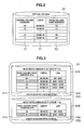
- the access information table 80 shown in Fig. 5 will be explained below.
- the micro processors in the I/O processors 101A, ... and 101N have access information tables 80 storing the access information for all the LDEVs, pages, and cache memory.
- the access information table 80 includes the average access count/min field 81, average access count/hour field 82, average access count/0K-83K field 83, average access count/84K-167K field 84, total access count field 85, cache memory's average access count/sec field 86, and access count field 87.
- the access count field 87 the access counts calculated for each item in the above fields are stored.
- '50' is entered in a box in the access count field 87 corresponding to the average access count/min field 81
- '1000' is entered in a box in the access count field 87 corresponding to the average access count/hour field 82
- '5' is entered in a box in the average access count/0K-83K field 83
- '3' is entered in a box in the access count field 87 corresponding to the average access count/84K-167K field 84
- '100000' is entered in a box in the access count field 87 corresponding to the total access count field 85
- '20' is entered in a box in the access count field 87 corresponding to the cache memory 103's average access count/sec field 86.
- Fig. 6 shows an example of a display screen image for making settings for the equalization processing.
- this display screen image 500 may be a display screen image on the SVP 105 in the memory apparatus 100, 200, ... or a display screen image on an information processor (not shown in the drawing) connected to the network 11.
- the display screen image 500 is configured so that one ticks either an automatic migration-setting field 510 or a manual migration-setting field 520 and the I/O processor 101 performs the equalization processing using the selected migration method.
- the manual migration-setting field 502 is ticked so that the manual migration will be performed.
- the manual migration-setting field 520 includes a number-of-times designation field 521 and time designation field 522.
- the number-of-times designation field 521 is where a user designates the number of times to perform the equalization processing and the time designation field 522 is where the user designates the time to perform that processing.
- the field 521 also includes a number-of-times of migration in-units-of-volumes field and a number-of-times of migration in-units-of-pages field. The user can input desired numbers in these fields.
- the time designation field 522 the user can set the time to perform the equalization processing.
- the time designation field 522 includes a migration in-units-of-volumes field 522A and migration in-units-of-pages field 522B. In these fields, the user can select the years, months, dates, and times to start and end the migration with the pull-down menus.
- an apply button 530 and cancel button 540 are displayed.
- the user chooses the apply button 530 to confirm the settings made in the automatic migration-setting field 510 or manual migration-setting field 520.
- the user chooses the cancel button 540 to cancel the settings made in the same.
- Fig. 7 shows an example of an X-type ECC group access count distribution map.
- the vertical axis of the distribution map indicates the number of ECC groups and the horizontal axis indicates the access count for designated ECC groups.
- an X-type distribution map shows that there is a big difference between the smallest access count and the largest access count.
- Fig. 8 shows an example of a Y-type ECC group access count distribution map.
- the vertical axis of the Y-type distribution map indicates the number of ECC groups and the horizontal axis indicates the access count for designated ECC groups.
- an Y-type distribution map shows that there is a small difference between the access counts.
- either the access count/hour, access count/day, access count/week, access count/month, or access count/year may be selected.
- a time interval may also be selected from among: every other hour, every other day, every other week, every other month, or every other year.
- an ECC group access count distribution map is type X
- an ECC group access count distribution map is type Y
- the access counts have been already equalized so there is no need to perform the equalization.
- a date migration determination table 90 the I/O processor 101A refers to when determining whether or not to perform data migration by comparing two page access count distribution maps.
- Fig. 10 shows the data migration determination table 90. This table is used when the I/O processor 101A determines whether or not to perform data migration to equalize access counts based on the relationships between the types of distribution maps and throughputs. Note that each I/O processor 101A, ... and 101N is capable of performing the equalization processing; however, for ease of explanation, the below explanation is based on the assumption that the I/O processor 101A performs the processing.
- a distribution map type field is divided into three sections corresponding to three cases - the case where the two distribution maps are both type X, the case where they are both type Y, and the case where both types are different. These sections are associated with the sections in the throughput field corresponding to three cases - the case where the throughput is high, the case where the throughput is medium, and the case where the throughput is low.
- values for high, medium, low throughputs may be determined by, for example, obtaining large and small throughput values from the load information table 70, calculating a mean value based on the above-obtained large and small values to be set as a medium value, and setting these large, medium, and small values as the high, medium, and low throughputs.
- this setting method there is no limitation to this setting method.
- whether or not to perform the data migration is determined as follows.
- the two page access count distribution maps are both type X
- data is migrated in units of pages regardless of the value - large, medium, small - or the throughput.
- the two maps are both type Y and if the value of the throughput is large or medium, data is not migrated, however, if the throughput value is small, data migration in volume units is performed.
- the two maps are of different types, data is not migrated.
- Fig. 11 shows a flowchart for the automatic data migration.
- Steps S101-106 are the processing of an ECC group level.
- the I/O processor 101A refers to the load information table 70 and performs data migration on a day and a time when the load is low.
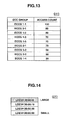
- it refers to the access information table 80 and ranks the ECC groups 1-1, 1-2, ... based on their access counts.
- the ranking order of the ECC groups 1-1, 1-2, ... based on their access counts will be, for example, as shown in Q10 in Fig. 13 .
- the access counts can be obtained by summing the access counts for the LDEVs, with reference to the access information table 80.
- the ECC groups are ranked in descending order of their access counts, from top to bottom.
- step S103 the I/O processor 101A creates an ECC group access count distribution map. Consequently, as explained with reference to Figs. 7 and 8 , a distribution map of type Y or type X is obtained.
- step S104 the I/O processor 101A checks the type of the distribution map and also checks whether there is any ECC group that should be subject to the access count equalization. If the distribution map is not type Y and there is (non-processed) ECC group(s) that should be subject to the access count equalization, it proceeds the processing. If the distribution map is type Y or there is no ECC group that should be subject to the access count equalization, the I/O processor 1 01A terminates the processing. This is because a Y-type map shows that the access counts have been equalized and there is no need to perform the equalization.
- step S105 the I/O processor 101A selects ECC groups having a large access count and a small access count.
- the ECC group with a large access count is ECCG1-1 (access count is 100) and the ECC group with a small access count is ECCG1-4 (access count is 20), so these two ECC groups are selected.
- the I/O processor 101A refers to the access information table 80 and ranks the LDEVs in the ECC groups 1-1 and 1-4 based on their access counts.
- Fig. 14 shows an example Q20 of the ranking order of the LDEVs in the ECC group 1-1 based on their access counts.
- the LDEVs are arranged in the descending order of their access counts, from the top to the bottom.
- Fig. 18 shows an example Q40 of the ranking order of the LDEVs in the ECC group 1-4 based on their access counts. Also in this list, the LDEVs are arranged in descending order of their access counts, from top to bottom.
- Steps S107-109 are the processing on an LDEV level.
- the I/O processor 101A creates LDEV access count distribution maps. In the above example, it creates a distribution map of the LDEV access counts for each of the ECC group 1-1 and the ECC group 1-4.
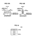
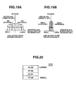
- Fig. 15 shows examples of a distribution map of the access counts for the LDEVs in the ECC group 1-1.
- the LDEV access count distribution map C in Fig. 15A indicates that there is a big difference between the access counts and the LDEV access count distribution map D in Fig. 15B indicates that the difference between the access counts is small. Note that an LDEV access count distribution map either of Fig. 15A or Fig. 15B is obtained for the ECC group 1-1.
- Fig. 19 shows examples of a distribution map of the access counts for the LDEVs in the ECC group 1-4.
- the LDEV access count distribution map C' in Fig. 19A indicates that there is a big difference between the access counts and the LDEV access count distribution map D' in Fig. 19B indicates that the difference between the access counts is small. Note that an LDEV access count distribution map either of Fig. 19A or Fig. 19B is obtained for ECC group 1-4.
- step S108 the I/O processor 101A checks whether there is an LDEV that should be subject to the access count equalization. If there is an LDEV that should be subject to the access count equalization (i.e., a non-processed LDEV) (S108: Yes), it proceeds the processing. If there is no such LDEV (S108:No), it returns to step S102.
- a non-processed LDEV i.e., a non-processed LDEV
- step S109 the I/O processor 101A selects an LDEV having the largest access count in the ECC group 1-1 having the large access count, and selects an LDEV having the smallest access count in the ECC group 1-4 having the small access count.
- Step S110 is the processing on a page level. More specifically, in step S110, the I/O processor 101A refers to the access information table 80 and ranks the pages in the LDEVs selected in step S109 based on their access counts.
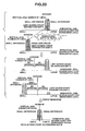
- Fig. 16 shows an example Q30 of the access ranking order of the pages in the LDEV selected in the ECC group 1-1 having the large access count
- Fig. 20 shows an example Q50 of the access ranking order of the pages in the LDEV selected in the ECC group 1-4 having the small access count.
- the pages are arranged in descending order of their access counts, from top to bottom.
- step S111 the I/O processor 101A creates page access count distribution maps based on the ranking order created in step S110.
- Fig. 17 shows examples of the page access count distribution maps created based on the access ranking order of the pages in the LDEV selected in the ECC group 1-1 having the large access count.
- the page access count distribution map E in Fig. 17A indicates that the difference between the access counts is large while the page access count distribution map F in Fig. 17B indicates that the difference between the access counts is small. Note that a page access count distribution map of either Fig. 17A or Fig. 17B is obtained for the above LDEV.
- Fig. 17 shows examples of the page access count distribution maps created based on the access ranking order of the pages in the LDEV selected in the ECC group 1-1 having the large access count.
- the page access count distribution map E in Fig. 17A indicates that the difference between the access counts is large while the page access count distribution map F in Fig. 17B indicates that the difference between the access counts is small. Note that a
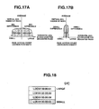
- FIG. 21 shows examples of the page access count distribution maps created based on the access ranking order of the pages in the LDEV selected in the ECC group 1-4 having the small access count.
- the page access count distribution map E' in Fig. 21A indicates that the difference between the access counts is large while the page access count distribution map F' in Fig. 21B indicates that the difference between the access counts is small. Note that a page access count distribution map either of Fig. 21A or Fig. 21B is obtained for the LDEV.
- step S112 the I/O processor 101A checks whether the two distribution maps created in step S111 are both type X, type Y, or of different types.
- step S113 the I/O processor 101A migrates the relevant data in units of pages. This is because an X-type map shows that the access counts widely range from a large number to a small number and so it is suitable to migrate data in small units, such as page units, only where migration is required. Moreover, because the migration is performed in small units, i.e., pages, the loads on the data can be kept small regardless of whether the current throughput is high, medium, or low, so there is no problem in performing the page migration. After the data migration, the I/O processor 101A returns to step S102 and repeats the steps of the processing on the ECC group level.
- Fig. 22 illustrates the data migration in units of pages.
- the difference between the page access counts can be reduced as shown in the upper and middle rows in Fig. 22 .
- the access counts can be equalized as shown in the bottom row in Fig. 22 .
- step S111 if the two distribution maps created in step S111 are of different types, the I/O processor 101A does not migrate the data but returns to step S108 to repeat the steps of the processing on the LDEV level. This is because, if the two distribution maps are of different types, units for data migration cannot be specified. Moreover, if the data were migrated, there is a risk that the current equalized state may be lost, so data migration is not performed.
- step S114 the I/O processor 101A checks whether the LDEV access count distribution maps obtained in step S107 are of the same type.
- Fig. 23 illustrates data migration in units of LDEVs.
- the difference between the LDEV access counts can be reduced as shown in the upper and middle rows in Fig. 23 .
- the access counts can be equalized as shown in the bottom row in Fig. 23 .
- the I/O processor 101A obtains the throughput as of the present time in step S115 and checks the throughput in step S116.
- step S117 the I/O processor 101A migrates relevant data in units of volumes. This is because a Y-type map shows that the access counts do not vary over a wide range and it is suitable to migrate data in large units such as volume units. Moreover, because the current throughput is low, the load caused by the data migration can be kept small, so there is no problem in performing the volume migration. After the migration, the I/O processor 101A returns to step S102 and repeats the steps for the processing on the ECC group level.
- step S107 if the LDEV access count distribution maps obtained in step S107 are of the same type and the throughput is high or medium, I/O processor 1 01A does not perform data migration but returns to step S108 to repeat the steps for the processing on the LDEV level.
- the page access count distribution maps created in step S111 are both type Y, which means that the access counts do not vary over a wide range and it is suitable to migrate data in large units such as volumes units, because the current throughput is not low, the data migration in large units, i.e., volumes units, will increase the load and may impair the equalized state, so data migration will not be performed.
- the manual data migration differs from the automatic data migration in that: the user designates parameters for the data migration method (S201); data is migrated on a date and a time designated the user (S202); and, after whether the parameters the user designates for the data migration method indicate the migration in units of pages or migration in units of volumes is checked (S210), whether or not the equalization processing has been repeated as many times as specified by the user's parameters is checked (S213).
- S201 the user designates parameters for the data migration method
- data is migrated on a date and a time designated the user
- S210 the parameters the user designates for the data migration method indicate the migration in units of pages or migration in units of volumes
- S213 whether or not the equalization processing has been repeated as many times as specified by the user's parameters is checked
- Fig. 12 is a flowchart illustrating the processing the I/O processor 101A executes for the manual data migration.
- step S201 the user designates the number of times to execute the volume migration and page migration, or the period - dates and times - during which the access count equalization processing is repeated.
- the user designates these parameters on the display screen image 500 shown in Fig. 6 .
- the I/O processor 101A then obtains the data designated on the display screen image 500.
- step S202 the I/O processor 101A executes data migration on the date and time designated by the user.
- step S203 the I/O processor 101A ranks the ECC groups 1-1, 1-2, ... based on their access counts.
- step S204 it creates a distribution map of the access counts for the ECC groups 1-1, 1-2, ....
- step S205 it selects an ECC group having a large access count and an ECC group having a small access count.
- step S206 the I/O processor 101A ranks the LDEVs in the selected ECC groups, based on their access counts.
- step S207 it selects LDEVs that should be subject to the access count equalization.
- step S208 it ranks the pages in the selected LDEV(s) based on their access counts.
- step S209 it creates page access count distribution maps.
- step S210 the I/O processor 101A checks whether the parameters the user designates for the data migration method indicate the migration in units of pages or the migration in units of volumes. If the parameters indicate the migration in units of pages, in step S211, the I/O processor 101A migrates relevant data in units of pages. Meanwhile, if the parameters indicate the migration in units of volumes, in step S212, the I/O processor 101A migrates the data in units of volumes.
- step S213 the I/O processor 101A checks whether the equalization processing has been repeated as many times as designated by the user-input parameters, and if not, it returns to step S203, but if so, it terminates the processing.
- an I/O processor automatically judges which data migration - data migration in page units or data migration in volume units - is most appropriate before migrating data. Therefore, in the storage system 1, the access count equalization can be performed optimally, thereby optimizing the entire storage system 1.
- this invention is applied to the storage system 1 that has: the host systems 10, 20, 30, ...; a plurality of disk drives (HDDs) for storing data transmitted from the host systems 10, 20, 30, ... via the network 11; and a memory apparatus including a plurality of parity groups (ECC groups) to maintain the reliability of the data in the disk drives (HDDs) and managing pool volumes in the parity groups using logical volumes and virtual volumes associated with those pool volumes.
- HDDs disk drives
- ECC groups parity groups
- the access information - the information about the access counts for the data stored in the disk drives (HDDs) - is stored in the access information table 80; the I/O processor 101A judges, when migrating data in the pool volumes to equalize the data access counts, which data migration - data migration in page units or data migration in volume units - is most appropriate based on the information in the access information table 80; based on that judgment, the I/O processor 101A migrates data in units of pages (S113) or in units of volumes (S117) so that the data access counts are equalized among the parity groups; and it repeats the data migration until the data access counts are equalized.
- This invention is not limited to that embodiment.
- the load information table 70 stores the throughput values that indicate the loads caused by the access to the data in the pool volumes and the I/O processor 101A refers to this table and performs the equalization processing on a day and a time when the load is smallest.
- the loads are not limited to the throughput values and the equalization processing may be performed not only on the days and times of light loads shown in the load information table 70.
- the I/O processor 101A creates an ECC group access count distribution map with reference to the access information table 80 (S103) and judges whether there is any ECC group that should be subject to the equalization according to the type of that map (S104).
- the distribution map creation method is not limited to that embodiment.
- the I/O processor 101A judges that there is an ECC group(s) that should be subject to the equalization, it creates an LDEV access count distribution map for each of the ECC group having the largest access count and the ECC group having the smallest access count with reference to the access information table 80 (S107), and judges whether there is any LDEV that should be subject to the equalization according to the types of the two created maps (S108).
- the distribution map creation method is not limited to the method in that embodiment.
- the I/O processor 101A judges that there are LDEVs that should be subject to the equalization, it creates a page access count distribution map for each of the LDEV having the largest access count and the LDEV having the smallest access count, with reference to the access information table 80 (S111).
- the distribution map creation method is not limited to the method in that embodiment.
- the display unit for setting either having the I/O processor 101A perform the processing on a predetermined timing or having the I/O processor 101A on a timing designated by the user is the display screen image 500.
- the display unit is not limited to the display screen image 500.
- This invention can be widely applied in storage systems and access count equalization methods for the storage systems.
Landscapes
- Engineering & Computer Science (AREA)
- Theoretical Computer Science (AREA)
- Human Computer Interaction (AREA)
- Physics & Mathematics (AREA)
- General Engineering & Computer Science (AREA)
- General Physics & Mathematics (AREA)
- Information Retrieval, Db Structures And Fs Structures Therefor (AREA)
Abstract
Description
- This application relates to and claims priority from Japanese Patent Application No.
2007-207232, filed on August 8, 2007 - The invention relates generally to a storage system and access count equalization method for the storage system and is suitable for use in, for example, a storage system having a function of migrating data between parity groups, from a high-use parity group to a low-use parity group, and an access count equalization method for the storage system.
- With the rapid increase in the amount of data in storage systems, users are required, at regular time intervals, to consider redesigning databases in the storage systems, including table definition and data size definition, as well as the review of the configurations of their storage systems, including system definition. The result of such a review of the system configuration may sometimes show unevenness in data access counts.
- In order to solve the unevenness in the data access counts, a function called 'volume migration' that equalizes the data access counts to optimize a storage system (for example, see Patent Document 1) has been in existence. With the volume migration function, which uses virtual volumes, a system administrator for the storage system is capable of migrating data between parity groups, from a high-use parity group to a low-use parity group, either in units of volumes (logical devices) or in units of pages.
- However, although the above volume migration function is capable of migrating data from a high-use parity group to a low-use parity group either in units of volumes or in units of pages, it cannot judge which data migration - data migration in units of volumes or data migration in units of pages - is more suitable. Therefore, although system administrators can have their storage systems perform the volume migration function by selecting either of the data migration methods, they never be sure that if they are having the storage systems perform the optimal volume migration function.
- This invention has been devised in light of the above points and aims to suggest a storage system capable of equalizing the access counts in the most appropriate units to optimize the entire storage system, and an access count equalization method for the storage system.
- One aspect of this invention provides a storage system having: a host system; a plurality of disk drives for storing data transmitted from the host system via a network; and a memory apparatus having a plurality of groups to maintain the reliability of data in the disk drives and managing pool volumes in the groups using logical volumes and virtual volumes associated with the pool volumes, comprising: an access information table storing access information, which is information about the access counts for the pieces of data stored in the disk drives; a judgment unit for, when migrating data in the pool volumes to equalize the data access counts, judging which data migration - data migration in units of pages or data migration in units of volumes - is most appropriate based on the information in the access information table; a data migration unit for performing, based on the judgment made by the judgment unit, data migration in units of pages or data migration in units of volumes so that the data access counts are equalized among the groups; and a control unit for controlling the judgment unit and the data migration unit so that the judgment and data migration is repeated until the data access counts are equalized.
- With the above configuration, when migrating data in the pool volumes to equalize the data access counts, which data migration - data migration in units of pages or data migration in units of volumes - is most appropriate is judged based on the information stored in the access information table storing access information, which is the information about the access counts for the data stored in the disk drives and, based on the judgment, data is migrated in units of pages or volumes so that the data access counts are equalized among the groups. The data migration is repeated until the data access counts are equalized among the groups.
- Equalizing the access counts in pages units results in equalizing the access counts in units of logical volumes, which further results in equalizing the access counts among, for example, the parity groups. By equalizing the data access counts in appropriate units, usage efficiency of the disk drives can be improved and the entire storage system can be optimized.
- According to aspects of this invention, a storage system capable of equalizing the access counts in the most appropriate units to optimize the entire storage system, and an access count equalization method for that storage system can be provided.
-
Fig. 1 shows the configuration of a storage system according to an embodiment of this invention. -
Fig. 2 shows a virtual volume management table according to an embodiment of this invention. -
Fig. 3 shows a pool volume management table according to an embodiment of this invention. -
Fig. 4 shows a load information table according to an embodiment of this invention. -
Fig. 5 shows an access information table according to an embodiment of this invention. -
Fig. 6 shows an example of a display screen image according to an embodiment of this invention. -
Fig. 7 shows an example of an access count distribution map according to an embodiment of this invention. -
Fig. 8 shows another example of an access count distribution map according to an embodiment of this invention. -
Fig. 9 explains a throughput calculation method according to an embodiment of this invention. -
Fig. 10 shows a data migration determination table according to an embodiment of this invention. -
Fig. 11 is a flowchart showing automatic equalization processing according to an embodiment of this invention. -
Fig. 12 is a flowchart showing manual equalization processing according to an embodiment of this invention. -
Fig. 13 shows an example of the ranking order of the access counts according to an embodiment of this invention. -
Fig. 14 shows another example of the ranking order of the access counts according to an embodiment of this invention. -
Fig. 15 shows an example of an access count distribution map according to an embodiment of this invention. -
Fig. 16 shows an example of the ranking order of the access counts according to an embodiment of this invention. -
Fig. 17 shows an example of an access count distribution map according to an embodiment of this invention. -
Fig. 18 shows an example of the ranking order for the access counts according to an embodiment of this invention. -
Fig. 19 shows an example of an access count distribution map according to an embodiment of this invention. -
Fig. 20 shows an example of the ranking order of the access counts according to an embodiment of this invention. -
Fig. 21 shows an example of an access count distribution map according to an embodiment of this invention. -
Fig. 22 shows data migration in units of pages according to an embodiment of this invention. -
Fig. 23 shows data migration in units of volumes according to an embodiment of this invention. - Embodiments of this invention will be explained below with reference to the attached drawings.
-
Fig. 1 shows the configuration of astorage system 1 according to an embodiment of this invention. As shown inFig. 1 , thestorage system 1 is configured so thathost systems memory apparatuses network 11. - The
host systems memory apparatuses network 11. Thehost systems - The
memory apparatus 100 includes I/O processors 101A, ... and 101N;adapter 102; cache memory (CM) 103; shared memory (SM) 104;SVP 105; fiber switch (FSW) 106; andvolume set 107. The I/O processors 101A, ... and 101N are connected thehost systems network 11 to enable data communication therebetween and also connected to theadapter 102 andfiber switch 106. Theadapter 102 is connected to, in addition to the I/O processors 101A, ... and 101N, thecache memory 103, sharedmemory 104 andSVP 105. Thefiber switch 106 is connected to thevolume set 107. - The I/
O processors 101A, ... and 101N are input/output processors. They each have a micro processor and a plurality of ports. The ports are the points where cables for data communication with thehost systems O processors 101A, ... and 101N each have various tables as well as the functions for performing equalization, which will be described later. - The
adapter 102 connects the I/O processors 101A, ... and 101N with thecache memory 103, sharedmemory 104, andSVP 105. Thecache memory 103 momentarily stores data transmitted from thehost systems network 11. The sharedmemory 104 stores various tables and other data. TheSVP 105 is a console PC (personal computer) for controlling thememory apparatuses fiber switch 106 connects the I/O processors 101A, ... and 101N with thevolume set 107. - The
volume set 107 includes a plurality of ECC (Error Correcting Code) groups 1-1, 1-2, ..., which are parity groups each consisting of four hard disk drives. Each ECC group 1-1, 1-2, ... is a unit where data redundancy is provided by having four hard disk drives. - Explanations for the
other memory apparatuses 200, ... will be omitted because, although the reference codes are different, they have the same configurations as thememory apparatus 100. -
Figs. 2-5 show the tables the micro processors in the I/O processors 101A, ... and 101N manage.Fig. 2 shows a virtual volume management table 50,Fig. 3 shows a pool volume management table 60,Fig. 4 shows a load information table 70, andFig. 5 shows an access information table 80. - First, the virtual volume management table 50 shown in
Fig. 2 will be explained below. The virtual volume management table 50 is used for the micro processors to manage the virtual volumes in thevolume set 107. As shown inFig. 2 , the virtual volume management table 50 has a virtualvolume address field 51, LDEV (logical device) number field (LDEV#) 52, and pool volumepage address field 53. - The virtual
volume address field 51 stores the addresses of the virtual volumes. TheLDEV number field 52 stores the LDEV numbers. Note that the LDEVs are the data units used in the ECC groups 1-1, 1-2, .... The pool volumepage address field 53 stores the page addresses of the pool volumes. Note that the pool volumes are real volumes associated with the virtual volumes and pages are the data units in the LDEVs. - In the virtual volume management table 50, pieces of data are stored while being associated with one another, for example, '00' is entered in the virtual
volume address field 51, '00:00:00' is entered in theLDEV number field 52, and '00' is entered in the pool volumepage address field 53. - The pool volume management table 60 shown in
Fig. 3 will be explained below. The pool volume management table 60 is used for the micro processors in the I/O processors 101A, ... and 101N to manage the pool volumes. The pool volume management table 60 consists of a plurality of tables 60A, 60B, ..., corresponding to the ECC groups 1-1, 1-2, ... in the volume set 107. As shown inFig. 3 , for example, the table 60A has a pool volumepage address field 61A,LDEV number field 62A, and LBA (Logical Block Address)field 63A. - The pool volume
page address field 61A stores the page addresses of the pool volumes. TheLDEV number field 62A stores the LDEV numbers. TheLBA field 63A stores LBAs. - In the table 60A in the pool volume management table 60, pieces of data are stored and associated with each other; for example, '00' is entered in the pool volume
page address field 61A, '00:00:00' is entered in theLDEV number field 62A, and '0K-83K' is entered in theLBA field 63A. - The load information table 70 shown in
Fig. 4 will be explained below. The load information table 70 is used for the micro processors in the I/O processors 101A, ... and 101N to calculate loads. Note that the load information table 70 is created for each pool volume. As shown inFig. 4 , the load information table 70 consists of atime field 71 and day fields 72-78. In thetime field 71, the same number of sections are provided as there are minutes in twenty-four hours. The day fields 72-78 correspond to Monday through Sunday. - As shown in
Fig. 4 , pieces of data are stored in the load information table 70. For example, '30' is entered in a box in theMonday field 72 corresponding to the '00:00-00:01' section in thetime field 71, '20' is entered in a box in theTuesday field 72 corresponding to the same section, ... and '0' is entered in a box in theSunday field 72 corresponding to the same section. - A method for calculating the load values stored in the load information table 70 will be explained below. A load value is calculated as the mean throughput (per minute) for LDEVs.
Fig. 9 illustrates the throughput calculation method. As shown inFig. 9 , the throughput for one page is calculated by (X-Y)*42/sec, where Y is the number of times thehost systems cache memory 103 in one second, X is the number of times the pages in the volume set 107 are accessed in one second, and one access is 42MB (82K LBA)/page. Thus, the micro processors in the I/O processors 101A, ... and 101N calculate the loads to be stored in the load information table 70. - The access information table 80 shown in
Fig. 5 will be explained below. The micro processors in the I/O processors 101A, ... and 101N have access information tables 80 storing the access information for all the LDEVs, pages, and cache memory. The access information table 80 includes the average access count/min field 81, average access count/hour field 82, average access count/0K-83K field 83, average access count/84K-167K field 84, totalaccess count field 85, cache memory's average access count/sec field 86, and access countfield 87. In theaccess count field 87, the access counts calculated for each item in the above fields are stored. - For example, as shown in
Fig. 5 , in the access information table 80, '50' is entered in a box in theaccess count field 87 corresponding to the average access count/min field 81, '1000' is entered in a box in theaccess count field 87 corresponding to the average access count/hour field 82, '5' is entered in a box in the average access count/0K-83K field 83, '3' is entered in a box in theaccess count field 87 corresponding to the average access count/84K-167K field 84, '100000' is entered in a box in theaccess count field 87 corresponding to the totalaccess count field 85, and '20' is entered in a box in theaccess count field 87 corresponding to thecache memory 103's average access count/sec field 86. - There are two patterns for having the
memory apparatuses Fig. 6 shows an example of a display screen image for making settings for the equalization processing. Note that thisdisplay screen image 500 may be a display screen image on theSVP 105 in thememory apparatus network 11. - The
display screen image 500 is configured so that one ticks either an automatic migration-settingfield 510 or a manual migration-settingfield 520 and the I/O processor 101 performs the equalization processing using the selected migration method. InFig. 6 , the manual migration-setting field 502 is ticked so that the manual migration will be performed. - The manual migration-setting
field 520 includes a number-of-times designation field 521 andtime designation field 522. The number-of-times designation field 521 is where a user designates the number of times to perform the equalization processing and thetime designation field 522 is where the user designates the time to perform that processing. - In the number-of-
times designation field 521, the year, month, date, and time to start the equalization processing can be selected with pull-down menus. Thefield 521 also includes a number-of-times of migration in-units-of-volumes field and a number-of-times of migration in-units-of-pages field. The user can input desired numbers in these fields. - In the
time designation field 522, the user can set the time to perform the equalization processing. Thetime designation field 522 includes a migration in-units-of-volumes field 522A and migration in-units-of-pages field 522B. In these fields, the user can select the years, months, dates, and times to start and end the migration with the pull-down menus. - At the bottom right of the
display screen image 500, an applybutton 530 and cancelbutton 540 are displayed. The user chooses the applybutton 530 to confirm the settings made in the automatic migration-settingfield 510 or manual migration-settingfield 520. The user chooses the cancelbutton 540 to cancel the settings made in the same. When the user makes desired settings in the automatic migration-settingfield 510 or manual migration-settingfield 520 and chooses the applybutton 530, those settings will be reflected in thestorage system 1. - The types of the access count distribution maps will be explained below. There are two types - type X and type Y - of distribution maps.
Fig. 7 shows an example of an X-type ECC group access count distribution map. The vertical axis of the distribution map indicates the number of ECC groups and the horizontal axis indicates the access count for designated ECC groups. As shown inFig. 7 , an X-type distribution map shows that there is a big difference between the smallest access count and the largest access count. - Meanwhile,
Fig. 8 shows an example of a Y-type ECC group access count distribution map. Just like in the case of type X, the vertical axis of the Y-type distribution map indicates the number of ECC groups and the horizontal axis indicates the access count for designated ECC groups. As shown inFig. 8 , an Y-type distribution map shows that there is a small difference between the access counts. - Note that, regarding the horizontal axes in both types of maps, either the access count/hour, access count/day, access count/week, access count/month, or access count/year may be selected. A time interval may also be selected from among: every other hour, every other day, every other week, every other month, or every other year.
- When an ECC group access count distribution map is type X, it is necessary to equalize the access counts by performing volume migration or page migration so that the map will be type Y. Meanwhile, when an ECC group access count distribution map is type Y, the access counts have been already equalized so there is no need to perform the equalization.
- Explanations will be given below for a date migration determination table 90 the I/
O processor 101A refers to when determining whether or not to perform data migration by comparing two page access count distribution maps.Fig. 10 shows the data migration determination table 90. This table is used when the I/O processor 101A determines whether or not to perform data migration to equalize access counts based on the relationships between the types of distribution maps and throughputs. Note that each I/O processor 101A, ... and 101N is capable of performing the equalization processing; however, for ease of explanation, the below explanation is based on the assumption that the I/O processor 101A performs the processing. - In the date migration determination table 90, a distribution map type field is divided into three sections corresponding to three cases - the case where the two distribution maps are both type X, the case where they are both type Y, and the case where both types are different. These sections are associated with the sections in the throughput field corresponding to three cases - the case where the throughput is high, the case where the throughput is medium, and the case where the throughput is low. Note that values for high, medium, low throughputs may be determined by, for example, obtaining large and small throughput values from the load information table 70, calculating a mean value based on the above-obtained large and small values to be set as a medium value, and setting these large, medium, and small values as the high, medium, and low throughputs. However, there is no limitation to this setting method.
- According to the data migration determination table 90 shown in
Fig. 10 , whether or not to perform the data migration is determined as follows. When the two page access count distribution maps are both type X, data is migrated in units of pages regardless of the value - large, medium, small - or the throughput. When the two maps are both type Y and if the value of the throughput is large or medium, data is not migrated, however, if the throughput value is small, data migration in volume units is performed. When the two maps are of different types, data is not migrated. - The procedure for the automatic data migration performed by the I/
O processor 101A to achieve the equalization will be explained below.Fig. 11 shows a flowchart for the automatic data migration. - Steps S101-106 are the processing of an ECC group level. In step S101, the I/
O processor 101A refers to the load information table 70 and performs data migration on a day and a time when the load is low. In step S102, it refers to the access information table 80 and ranks the ECC groups 1-1, 1-2, ... based on their access counts. - The ranking order of the ECC groups 1-1, 1-2, ... based on their access counts will be, for example, as shown in Q10 in
Fig. 13 . The access counts can be obtained by summing the access counts for the LDEVs, with reference to the access information table 80. In the list ofFig. 13 , the ECC groups are ranked in descending order of their access counts, from top to bottom. - In step S103, the I/
O processor 101A creates an ECC group access count distribution map. Consequently, as explained with reference toFigs. 7 and 8 , a distribution map of type Y or type X is obtained. - In step S104, the I/
O processor 101A checks the type of the distribution map and also checks whether there is any ECC group that should be subject to the access count equalization. If the distribution map is not type Y and there is (non-processed) ECC group(s) that should be subject to the access count equalization, it proceeds the processing. If the distribution map is type Y or there is no ECC group that should be subject to the access count equalization, the I/O processor 1 01A terminates the processing. This is because a Y-type map shows that the access counts have been equalized and there is no need to perform the equalization. - In step S105, the I/
O processor 101A selects ECC groups having a large access count and a small access count. In the example shown inFig. 13 , the ECC group with a large access count is ECCG1-1 (access count is 100) and the ECC group with a small access count is ECCG1-4 (access count is 20), so these two ECC groups are selected. - In step S106, the I/
O processor 101A refers to the access information table 80 and ranks the LDEVs in the ECC groups 1-1 and 1-4 based on their access counts.Fig. 14 shows an example Q20 of the ranking order of the LDEVs in the ECC group 1-1 based on their access counts. In this list, the LDEVs are arranged in the descending order of their access counts, from the top to the bottom.Fig. 18 shows an example Q40 of the ranking order of the LDEVs in the ECC group 1-4 based on their access counts. Also in this list, the LDEVs are arranged in descending order of their access counts, from top to bottom. - Steps S107-109 are the processing on an LDEV level. In step S107, the I/
O processor 101A creates LDEV access count distribution maps. In the above example, it creates a distribution map of the LDEV access counts for each of the ECC group 1-1 and the ECC group 1-4.Fig. 15 shows examples of a distribution map of the access counts for the LDEVs in the ECC group 1-1. The LDEV access count distribution map C inFig. 15A indicates that there is a big difference between the access counts and the LDEV access count distribution map D inFig. 15B indicates that the difference between the access counts is small. Note that an LDEV access count distribution map either ofFig. 15A or Fig. 15B is obtained for the ECC group 1-1.Fig. 19 shows examples of a distribution map of the access counts for the LDEVs in the ECC group 1-4. The LDEV access count distribution map C' inFig. 19A indicates that there is a big difference between the access counts and the LDEV access count distribution map D' inFig. 19B indicates that the difference between the access counts is small. Note that an LDEV access count distribution map either ofFig. 19A or Fig. 19B is obtained for ECC group 1-4. - In step S108, the I/
O processor 101A checks whether there is an LDEV that should be subject to the access count equalization. If there is an LDEV that should be subject to the access count equalization (i.e., a non-processed LDEV) (S108: Yes), it proceeds the processing. If there is no such LDEV (S108:No), it returns to step S102. - In step S109, the I/
O processor 101A selects an LDEV having the largest access count in the ECC group 1-1 having the large access count, and selects an LDEV having the smallest access count in the ECC group 1-4 having the small access count. - Step S110 is the processing on a page level. More specifically, in step S110, the I/
O processor 101A refers to the access information table 80 and ranks the pages in the LDEVs selected in step S109 based on their access counts.Fig. 16 shows an example Q30 of the access ranking order of the pages in the LDEV selected in the ECC group 1-1 having the large access count, andFig. 20 shows an example Q50 of the access ranking order of the pages in the LDEV selected in the ECC group 1-4 having the small access count. In both lists inFigs. 16 and20 , the pages are arranged in descending order of their access counts, from top to bottom. - In step S111, the I/
O processor 101A creates page access count distribution maps based on the ranking order created in step S110.Fig. 17 shows examples of the page access count distribution maps created based on the access ranking order of the pages in the LDEV selected in the ECC group 1-1 having the large access count. The page access count distribution map E inFig. 17A indicates that the difference between the access counts is large while the page access count distribution map F inFig. 17B indicates that the difference between the access counts is small. Note that a page access count distribution map of eitherFig. 17A or Fig. 17B is obtained for the above LDEV.Fig. 21 shows examples of the page access count distribution maps created based on the access ranking order of the pages in the LDEV selected in the ECC group 1-4 having the small access count. The page access count distribution map E' inFig. 21A indicates that the difference between the access counts is large while the page access count distribution map F' inFig. 21B indicates that the difference between the access counts is small. Note that a page access count distribution map either ofFig. 21A or Fig. 21B is obtained for the LDEV. - In step S112, the I/
O processor 101A checks whether the two distribution maps created in step S111 are both type X, type Y, or of different types. - If the two distribution maps are both type X, in step S113, the I/
O processor 101A migrates the relevant data in units of pages. This is because an X-type map shows that the access counts widely range from a large number to a small number and so it is suitable to migrate data in small units, such as page units, only where migration is required. Moreover, because the migration is performed in small units, i.e., pages, the loads on the data can be kept small regardless of whether the current throughput is high, medium, or low, so there is no problem in performing the page migration. After the data migration, the I/O processor 101A returns to step S102 and repeats the steps of the processing on the ECC group level. -
Fig. 22 illustrates the data migration in units of pages. By migrating relevant data in units of pages based on the above-created page access count distribution maps E and E', the difference between the page access counts can be reduced as shown in the upper and middle rows inFig. 22 . By repeating the data migration, the access counts can be equalized as shown in the bottom row inFig. 22 . - Meanwhile, if the two distribution maps created in step S111 are of different types, the I/
O processor 101A does not migrate the data but returns to step S108 to repeat the steps of the processing on the LDEV level. This is because, if the two distribution maps are of different types, units for data migration cannot be specified. Moreover, if the data were migrated, there is a risk that the current equalized state may be lost, so data migration is not performed. - Meanwhile, if the two distribution maps created in step S111 are both type Y, in step S114, the I/
O processor 101A checks whether the LDEV access count distribution maps obtained in step S107 are of the same type. -
Fig. 23 illustrates data migration in units of LDEVs. By migrating relevant data in units of volumes based on the above LDEV access count distribution maps D and D', the difference between the LDEV access counts can be reduced as shown in the upper and middle rows inFig. 23 . By repeating the data migration, the access counts can be equalized as shown in the bottom row inFig. 23 . - If the LDEV access count distribution maps obtained in step S107 are of the same type, the I/
O processor 101A obtains the throughput as of the present time in step S115 and checks the throughput in step S116. - If the current throughput is low, in step S117, the I/
O processor 101A migrates relevant data in units of volumes. This is because a Y-type map shows that the access counts do not vary over a wide range and it is suitable to migrate data in large units such as volume units. Moreover, because the current throughput is low, the load caused by the data migration can be kept small, so there is no problem in performing the volume migration. After the migration, the I/O processor 101A returns to step S102 and repeats the steps for the processing on the ECC group level. - Meanwhile, if the LDEV access count distribution maps obtained in step S107 are of the same type and the throughput is high or medium, I/
O processor 1 01A does not perform data migration but returns to step S108 to repeat the steps for the processing on the LDEV level. This is because although the page access count distribution maps created in step S111 are both type Y, which means that the access counts do not vary over a wide range and it is suitable to migrate data in large units such as volumes units, because the current throughput is not low, the data migration in large units, i.e., volumes units, will increase the load and may impair the equalized state, so data migration will not be performed. - Accordingly, with the above-explained automatic access count equalization processing in the
storage system 1, when migrating data within parity groups, i.e., ECC groups, for example, from a high-use group to a low-use group, it is possible to specify which data migration - either the data migration in page units or data migration in volume units - is most appropriate. Accordingly, optimal access count equalization can be performed in thestorage system 1, optimizing theentire storage system 1. - The outline of the manual data migration, which is manually instructed by the user to achieve the equalization will be explained below. The manual data migration differs from the automatic data migration in that: the user designates parameters for the data migration method (S201); data is migrated on a date and a time designated the user (S202); and, after whether the parameters the user designates for the data migration method indicate the migration in units of pages or migration in units of volumes is checked (S210), whether or not the equalization processing has been repeated as many times as specified by the user's parameters is checked (S213). The other steps are the same as those in the automatic data migration, so detailed explanations will be omitted.
- The procedure of the manual data migration manually instructed by the user to achieve the equalization will be explained below.
Fig. 12 is a flowchart illustrating the processing the I/O processor 101A executes for the manual data migration. - First, in step S201, the user designates the number of times to execute the volume migration and page migration, or the period - dates and times - during which the access count equalization processing is repeated. The user designates these parameters on the
display screen image 500 shown inFig. 6 . The I/O processor 101A then obtains the data designated on thedisplay screen image 500. In step S202, the I/O processor 101A executes data migration on the date and time designated by the user. - In step S203, the I/
O processor 101A ranks the ECC groups 1-1, 1-2, ... based on their access counts. In step S204, it creates a distribution map of the access counts for the ECC groups 1-1, 1-2, .... In step S205, it selects an ECC group having a large access count and an ECC group having a small access count. - Then, in step S206, the I/
O processor 101A ranks the LDEVs in the selected ECC groups, based on their access counts. In step S207, it selects LDEVs that should be subject to the access count equalization. In step S208, it ranks the pages in the selected LDEV(s) based on their access counts. In step S209, it creates page access count distribution maps. - In step S210, the I/
O processor 101A checks whether the parameters the user designates for the data migration method indicate the migration in units of pages or the migration in units of volumes. If the parameters indicate the migration in units of pages, in step S211, the I/O processor 101A migrates relevant data in units of pages. Meanwhile, if the parameters indicate the migration in units of volumes, in step S212, the I/O processor 101A migrates the data in units of volumes. - In step S213, the I/
O processor 101A checks whether the equalization processing has been repeated as many times as designated by the user-input parameters, and if not, it returns to step S203, but if so, it terminates the processing. - Accordingly, in the equalization by means of the manual data migration, just as in the case of the automatic data migration, an I/O processor automatically judges which data migration - data migration in page units or data migration in volume units - is most appropriate before migrating data. Therefore, in the
storage system 1, the access count equalization can be performed optimally, thereby optimizing theentire storage system 1. - In the above embodiment, this invention is applied to the
storage system 1 that has: thehost systems host systems network 11; and a memory apparatus including a plurality of parity groups (ECC groups) to maintain the reliability of the data in the disk drives (HDDs) and managing pool volumes in the parity groups using logical volumes and virtual volumes associated with those pool volumes. In thestorage system 1, the access information - the information about the access counts for the data stored in the disk drives (HDDs) - is stored in the access information table 80; the I/O processor 101A judges, when migrating data in the pool volumes to equalize the data access counts, which data migration - data migration in page units or data migration in volume units - is most appropriate based on the information in the access information table 80; based on that judgment, the I/O processor 101A migrates data in units of pages (S113) or in units of volumes (S117) so that the data access counts are equalized among the parity groups; and it repeats the data migration until the data access counts are equalized. This invention, however, is not limited to that embodiment. - Also, in the above embodiment, the load information table 70 stores the throughput values that indicate the loads caused by the access to the data in the pool volumes and the I/
O processor 101A refers to this table and performs the equalization processing on a day and a time when the load is smallest. However, the loads are not limited to the throughput values and the equalization processing may be performed not only on the days and times of light loads shown in the load information table 70. - Further, in the above embodiment, the I/
O processor 101A creates an ECC group access count distribution map with reference to the access information table 80 (S103) and judges whether there is any ECC group that should be subject to the equalization according to the type of that map (S104). However, the distribution map creation method is not limited to that embodiment. - Furthermore, in the above embodiment, when the I/
O processor 101A judges that there is an ECC group(s) that should be subject to the equalization, it creates an LDEV access count distribution map for each of the ECC group having the largest access count and the ECC group having the smallest access count with reference to the access information table 80 (S107), and judges whether there is any LDEV that should be subject to the equalization according to the types of the two created maps (S108). However, the distribution map creation method is not limited to the method in that embodiment. - Moreover, in the above embodiment, when the I/
O processor 101A judges that there are LDEVs that should be subject to the equalization, it creates a page access count distribution map for each of the LDEV having the largest access count and the LDEV having the smallest access count, with reference to the access information table 80 (S111). However, the distribution map creation method is not limited to the method in that embodiment. - Further, in the above embodiment, there are two types of distribution maps created when the I/
O processor 101A judges that there are LDEVs that should be subject to the equalization, i.e., type X indicating that the difference between the page access counts is large, and type Y indicating the difference is small, and when the two distribution maps are both type X (S112: type X), data is migrated in units of pages (S113). - Furthermore, in the above embodiment, there are two types of distribution maps created when the I/
O processor 1 01A judges that there are LDEVs that should be subject to the equalization, i.e., type X indicating that the difference between the page access counts is large and type Y indicating that the difference is small; and there are two types of distribution maps created when the I/O processor 101A judges that there are ECC groups that should be subject to the equalization, i.e., type X indicating that the difference between the LDEV access counts is large and type Y indicating that the difference is small; and when the the distribution maps created when the I/O processor 101A judges that there are LDEVs to be subject to the equalization are both of the latter type (S112: type Y) and when the distribution maps created when the I/O processor 101A judges that there are ECC groups to be subject to the equalization are of the same type (S114: Yes), it calculates the load as of the present time (S115), and if that load is small (S116: Small), it migrates data in units of volumes (S117). However, this invention is not limited to that embodiment. - Also, in the above embodiment, the display unit for setting either having the I/
O processor 101A perform the processing on a predetermined timing or having the I/O processor 101A on a timing designated by the user, is thedisplay screen image 500. However, the display unit is not limited to thedisplay screen image 500. - This invention can be widely applied in storage systems and access count equalization methods for the storage systems.
- While the invention has been described with respect to a limited number of embodiments, those skilled in the art, having the benefit of this disclosure, will appreciate that other embodiments can be devised which do not depart from the scope of the invention as disclosed herein. Accordingly, the scope of the invention should be limited only by the attached claims.
Claims (15)
- A storage system having: a host system; a plurality of disk drives for storing data transmitted from the host system via a network; and a memory apparatus having a plurality of groups to maintain the reliability of data in the disk drives and managing pool volumes in the groups using logical volumes and virtual volumes associated with the pool volumes, comprising:an access information table storing access information, which is information about the access counts for the pieces of data stored in the disk drives;a judgment unit for, when migrating data in the pool volumes to equalize the data access counts, judging which data migration - data migration in units of pages or data migration in units of volumes - is most appropriate based on the information in the access information table;a data migration unit for performing, based on the judgment made by the judgment unit, data migration in units of pages or data migration in units of volumes so that the data access counts are equalized among the groups; anda control unit for controlling the judgment unit and the data migration unit so that the judgment and data migration is repeated until the data access counts are equalized.
- The storage system according to claim 1,
further comprising a load information table storing load information, which is the information about the load caused by the access to the data in the pool volumes, and
wherein, judgment by the judgment unit and data migration by the data migration unit are performed at a time of light load, which is specified according to the load information table. - The storage system according to claim 1 or claim 2, wherein the judgment unit comprises:a first distribution map creation portion for creating a group access count distribution map with reference to the access information table; anda first judgment portion for judging whether there is any group that should be subject to the equalization according to the type of the group access count distribution map created by the first distribution map creation unit.
- The storage system according to claim 3, wherein the judgment unit further comprises:a second distribution map creation portion for, when the first judgment portion judges that there is group(s) that should be subject to the equalization, creating a logical volume access count distribution map for each of the group having the largest access count and the group having the smallest access count, with reference to the access information table; anda second judgment portion for judging whether there is any logical volume that should be subject to the equalization according to the types of the logical volume access count distribution maps created by the second distribution map creation unit.
- The storage system according to claim 4, wherein the judgment unit further comprises a third distribution map creation portion for, when the second judgment portion judges that there is a logical volume(s) that should be subject to the equalization, creating a page access count distribution map for each of the logical volume having the largest access count and the logical volume having the smallest access count, with reference to the access information table.
- The storage system according to claim 5, wherein there are two types of distribution maps the third distribution map creation portion creates, i.e., a first type indicating that the difference between the page access counts is large and a second type indicating that the difference is small; and
when the two distribution maps the third distribution map creation portion creates are both of the first type, the data migration unit migrates data in units of pages. - The storage system according to claim 5, wherein there are two types of distribution maps the third distribution map creation portion creates, i.e., a first type indicating that the difference between the page access counts is large and a second type indicating that the difference is small;
there are two types of distribution maps the second distribution map creation portion creates, i.e., a third type indicating that the difference between the logical volume access counts is large and a fourth type indicating that the difference is small; and
when the two distribution maps the third distribution map creation portion creates are both of the second type and the distribution maps the second distribution map creation portion creates are both of the same type, the load as of the present time is calculated and, if that load is small, the data migration unit migrates the data in units of volumes. - The storage system according to any of claims 1 to 7, further comprising a display unit used for selecting either having the control unit perform the processing at a predetermined time or having the control unit perform the processing at a time designated by a user.
- An access count equalization method for a storage system,
wherein the storage system comprises: a host system; a plurality of disk drives for storing data transmitted from the host system via a network; and a memory apparatus having a plurality of groups to maintain the reliability of data in the disk drives and managing pool volumes in the groups using logical volumes and virtual volumes associated with the pool volumes,
the method comprising the steps of:judging, when migrating data in the pool volumes to equalize the data access counts, which data migration - data migration in units of pages or data migration in units of volumes - is most appropriate based on the information stored in an access information table storing access information, which is information about the access counts for the data stored in the disk drives;performing, based on the judgment made in the judgment step, data migration in units of pages or data migration in units of volumes so that the data access counts are equalized among the groups; andrepeating the judgment step and the data migration step until the data access counts are equalized. - The access count equalization method for a storage system according to claim 9,
wherein the judgment step and data migration step are performed at a time of light load, which is specified according to the load information table when the load stored in the load information table is small. - The access count equalization method for a storage system according to claim 9 or claim 10, wherein
the step of judging which data migration is most appropriate comprises the steps of:creating a group access count distribution map with reference to the access information table; andjudging whether there is any group that should be subject to the equalization according to the type of the group access count distribution map created in the above step. - The access count equalization method for a storage system according to claim 11, wherein
the step of judging which data migration is most appropriate comprises the steps of:when it is judged that there is a group(s) that should be subject to the equalization, creating a logical volume access count distribution map for each of the group having the largest access count and the group having the smallest access count, with reference to the access information table; andjudging whether there is any logical volume that should be subject to the equalization according to the types of the logical volume access count distribution maps created in the above step. - The access count equalization method for a storage system according to claim 12, wherein
the step of judging which data migration is most appropriate comprises the steps of:when it is judged that there is logical volume(s) that should be subject to the equalization, creating page an access count distribution map for each of the logical volume having the largest access count and the logical volume having the smallest access count, with reference to the access information table. - The access count equalization method for a storage system according to claim 13, wherein
there are two types of distribution maps created when it is judged that there is a logical volume(s) that should be subject to the equalization, i.e., a first type indicating that the difference between the page access counts is large and a second type indicating that the difference is small; and
when the two distribution maps are both of the first type, data is migrated in units of pages in the data migration step. - The access count equalization method for a storage system according to claim 13, wherein
there are two types of distribution maps created when it is judged that there is a logical volume(s) that should be subject to the equalization, i.e., a first type indicating that the difference between the page access counts is large and a second type indicating that the difference is small;
there are two types of distribution maps created when it is judged that there is a group(s) that should be subject to the equalization, i.e., a third type indicating that difference between the logical volume access counts is large and a fourth type indicating that the difference is small; and
when the two distribution maps created when it is judged that there is a logical volume(s) that should be subject to the equalization are both of the second type and the distribution maps created when it is judged that there is a group(s) that should be subject to the equalization are both of the same type, the load as of the present time is calculated and, if that load is small, data is migrated in units of volumes in the data migration step.
Applications Claiming Priority (1)
| Application Number | Priority Date | Filing Date | Title |
|---|---|---|---|
| JP2007207232A JP2009043016A (en) | 2007-08-08 | 2007-08-08 | Storage system and access equalization method of storage system |
Publications (2)
| Publication Number | Publication Date |
|---|---|
| EP2026187A2 true EP2026187A2 (en) | 2009-02-18 |
| EP2026187A3 EP2026187A3 (en) | 2012-07-04 |
Family
ID=39944412
Family Applications (1)
| Application Number | Title | Priority Date | Filing Date |
|---|---|---|---|
| EP08250168A Withdrawn EP2026187A3 (en) | 2007-08-08 | 2008-01-14 | Storage system and access count equalization method therefor |
Country Status (3)
| Country | Link |
|---|---|
| US (1) | US7949827B2 (en) |
| EP (1) | EP2026187A3 (en) |
| JP (1) | JP2009043016A (en) |
Cited By (1)
| Publication number | Priority date | Publication date | Assignee | Title |
|---|---|---|---|---|
| CN113407114A (en) * | 2021-05-26 | 2021-09-17 | 青海师范大学 | Online capacity expansion IO scheduling method based on hot data and delete repeat operation |
Families Citing this family (34)
| Publication number | Priority date | Publication date | Assignee | Title |
|---|---|---|---|---|
| JP2010015446A (en) * | 2008-07-04 | 2010-01-21 | Hitachi Ltd | Storage device and power control method |
| JP5215898B2 (en) * | 2009-02-10 | 2013-06-19 | 株式会社日立製作所 | File server, file management system, and file relocation method |
| US20110029729A1 (en) * | 2009-07-30 | 2011-02-03 | Lsi Corporation | Erasure coded data storage capacity and power management |
| JP5130313B2 (en) * | 2010-04-02 | 2013-01-30 | 株式会社日立製作所 | Management system and computer system management method |
| JP5065434B2 (en) * | 2010-04-06 | 2012-10-31 | 株式会社日立製作所 | Management method and management apparatus |
| EP2693704B1 (en) * | 2011-04-28 | 2018-06-06 | Huawei Technologies Co., Ltd. | Method, regional management entity and system for virtual network migration |
| WO2015189988A1 (en) * | 2014-06-13 | 2015-12-17 | 株式会社日立製作所 | Management server which outputs file relocation policy, and storage system |
| US9477453B1 (en) * | 2015-06-24 | 2016-10-25 | Intel Corporation | Technologies for shadow stack manipulation for binary translation systems |
| CN108228672B (en) * | 2016-12-22 | 2022-05-03 | 阿里巴巴集团控股有限公司 | Metadata migration method, device, system and equipment |
| US11947489B2 (en) | 2017-09-05 | 2024-04-02 | Robin Systems, Inc. | Creating snapshots of a storage volume in a distributed storage system |
| US11748203B2 (en) | 2018-01-11 | 2023-09-05 | Robin Systems, Inc. | Multi-role application orchestration in a distributed storage system |
| US11392363B2 (en) | 2018-01-11 | 2022-07-19 | Robin Systems, Inc. | Implementing application entrypoints with containers of a bundled application |
| US11582168B2 (en) | 2018-01-11 | 2023-02-14 | Robin Systems, Inc. | Fenced clone applications |
| US11099937B2 (en) | 2018-01-11 | 2021-08-24 | Robin Systems, Inc. | Implementing clone snapshots in a distributed storage system |
| US11023328B2 (en) | 2018-07-30 | 2021-06-01 | Robin Systems, Inc. | Redo log for append only storage scheme |
| US10976938B2 (en) | 2018-07-30 | 2021-04-13 | Robin Systems, Inc. | Block map cache |
| US11036439B2 (en) | 2018-10-22 | 2021-06-15 | Robin Systems, Inc. | Automated management of bundled applications |
| US10908848B2 (en) | 2018-10-22 | 2021-02-02 | Robin Systems, Inc. | Automated management of bundled applications |
| US11086725B2 (en) | 2019-03-25 | 2021-08-10 | Robin Systems, Inc. | Orchestration of heterogeneous multi-role applications |
| US11256434B2 (en) | 2019-04-17 | 2022-02-22 | Robin Systems, Inc. | Data de-duplication |
| US11226847B2 (en) | 2019-08-29 | 2022-01-18 | Robin Systems, Inc. | Implementing an application manifest in a node-specific manner using an intent-based orchestrator |
| US11249851B2 (en) | 2019-09-05 | 2022-02-15 | Robin Systems, Inc. | Creating snapshots of a storage volume in a distributed storage system |
| US11520650B2 (en) | 2019-09-05 | 2022-12-06 | Robin Systems, Inc. | Performing root cause analysis in a multi-role application |
| US11113158B2 (en) | 2019-10-04 | 2021-09-07 | Robin Systems, Inc. | Rolling back kubernetes applications |
| US11347684B2 (en) | 2019-10-04 | 2022-05-31 | Robin Systems, Inc. | Rolling back KUBERNETES applications including custom resources |
| US11403188B2 (en) | 2019-12-04 | 2022-08-02 | Robin Systems, Inc. | Operation-level consistency points and rollback |
| US11108638B1 (en) * | 2020-06-08 | 2021-08-31 | Robin Systems, Inc. | Health monitoring of automatically deployed and managed network pipelines |
| US11528186B2 (en) | 2020-06-16 | 2022-12-13 | Robin Systems, Inc. | Automated initialization of bare metal servers |
| US11740980B2 (en) | 2020-09-22 | 2023-08-29 | Robin Systems, Inc. | Managing snapshot metadata following backup |
| US11743188B2 (en) | 2020-10-01 | 2023-08-29 | Robin Systems, Inc. | Check-in monitoring for workflows |
| US11271895B1 (en) | 2020-10-07 | 2022-03-08 | Robin Systems, Inc. | Implementing advanced networking capabilities using helm charts |
| US11456914B2 (en) | 2020-10-07 | 2022-09-27 | Robin Systems, Inc. | Implementing affinity and anti-affinity with KUBERNETES |
| US11750451B2 (en) | 2020-11-04 | 2023-09-05 | Robin Systems, Inc. | Batch manager for complex workflows |
| US11556361B2 (en) | 2020-12-09 | 2023-01-17 | Robin Systems, Inc. | Monitoring and managing of complex multi-role applications |
Citations (2)
| Publication number | Priority date | Publication date | Assignee | Title |
|---|---|---|---|---|
| JP2001067187A (en) | 1999-08-30 | 2001-03-16 | Hitachi Ltd | Storage sub-system and its control method |
| JP2007207232A (en) | 2006-01-30 | 2007-08-16 | Internatl Business Mach Corp <Ibm> | System and method of spatial/tabular data presentation |
Family Cites Families (7)
| Publication number | Priority date | Publication date | Assignee | Title |
|---|---|---|---|---|
| JP2001337790A (en) * | 2000-05-24 | 2001-12-07 | Hitachi Ltd | Storage unit and its hierarchical management control method |
| US6678795B1 (en) * | 2000-08-15 | 2004-01-13 | International Business Machines Corporation | Method and apparatus for memory prefetching based on intra-page usage history |
| US7937551B2 (en) * | 2003-01-21 | 2011-05-03 | Dell Products L.P. | Storage systems having differentiated storage pools |
| US7197490B1 (en) * | 2003-02-10 | 2007-03-27 | Network Appliance, Inc. | System and method for lazy-copy sub-volume load balancing in a network attached storage pool |
| US7185163B1 (en) * | 2003-09-03 | 2007-02-27 | Veritas Operating Corporation | Balancing most frequently used file system clusters across a plurality of disks |
| JP4349871B2 (en) * | 2003-09-09 | 2009-10-21 | 株式会社日立製作所 | File sharing apparatus and data migration method between file sharing apparatuses |
| JP2008134712A (en) * | 2006-11-27 | 2008-06-12 | Hitachi Ltd | File sharing system, file sharing device, and method for migrating volume for file sharing |
-
2007
- 2007-08-08 JP JP2007207232A patent/JP2009043016A/en active Pending
-
2008
- 2008-01-14 EP EP08250168A patent/EP2026187A3/en not_active Withdrawn
- 2008-01-18 US US12/010,047 patent/US7949827B2/en not_active Expired - Fee Related
Patent Citations (2)
| Publication number | Priority date | Publication date | Assignee | Title |
|---|---|---|---|---|
| JP2001067187A (en) | 1999-08-30 | 2001-03-16 | Hitachi Ltd | Storage sub-system and its control method |
| JP2007207232A (en) | 2006-01-30 | 2007-08-16 | Internatl Business Mach Corp <Ibm> | System and method of spatial/tabular data presentation |
Cited By (2)
| Publication number | Priority date | Publication date | Assignee | Title |
|---|---|---|---|---|
| CN113407114A (en) * | 2021-05-26 | 2021-09-17 | 青海师范大学 | Online capacity expansion IO scheduling method based on hot data and delete repeat operation |
| CN113407114B (en) * | 2021-05-26 | 2022-03-04 | 青海师范大学 | Online capacity expansion IO scheduling method based on hot data and delete repeat operation |
Also Published As
| Publication number | Publication date |
|---|---|
| JP2009043016A (en) | 2009-02-26 |
| US20090254701A1 (en) | 2009-10-08 |
| EP2026187A3 (en) | 2012-07-04 |
| US7949827B2 (en) | 2011-05-24 |
Similar Documents
| Publication | Publication Date | Title |
|---|---|---|
| EP2026187A2 (en) | Storage system and access count equalization method therefor | |
| US7441080B2 (en) | Method of and system for controlling attributes of a plurality of storage devices | |
| US6959360B2 (en) | Data storage system and method of hierarchical control thereof | |
| US8271991B2 (en) | Method of analyzing performance in a storage system | |
| US8281085B2 (en) | Storage system construction managing device and construction management method | |
| US8683162B2 (en) | Computer system and method of managing storage system monitoring access performance for risky pool detection | |
| US8261031B2 (en) | Device and method to manage migration volume selection | |
| EP2399190B1 (en) | Storage system and method for operating storage system | |
| US8645737B2 (en) | Power-saving control apparatus and method | |
| US9116632B2 (en) | Storage management system | |
| US6954824B2 (en) | Method, system, and program for determining a configuration of a logical array including a plurality of storage devices | |
| US7587553B2 (en) | Storage controller, and logical volume formation method for the storage controller | |
| US20090150639A1 (en) | Management apparatus and management method | |
| US20050086093A1 (en) | Asset management systems | |
| WO2012104912A1 (en) | Data storage apparatus and data management method | |
| US20060069861A1 (en) | Method and apparatus for storage pooling and provisioning for journal based strorage and recovery | |
| US20100125715A1 (en) | Storage System and Operation Method Thereof | |
| US20030033132A1 (en) | Technique and interface for storage system resource assignment | |
| US8589651B2 (en) | Method for supporting migration destination decision and management system | |
| EP2813941A2 (en) | Storage system and operation management method of storage system | |
| WO2010134134A1 (en) | Storage system comprising plurality of processor units | |
| US8261038B2 (en) | Method and system for allocating storage space | |
| US20050273556A1 (en) | Method and system for providing a recommended allocation of data storage space | |
| US20080288560A1 (en) | Storage management method using data migration | |
| US20030149835A1 (en) | Method and computer for data set separation |
Legal Events
| Date | Code | Title | Description |
|---|---|---|---|
| PUAI | Public reference made under article 153(3) epc to a published international application that has entered the european phase |
Free format text: ORIGINAL CODE: 0009012 |
|
| 17P | Request for examination filed |
Effective date: 20080204 |
|
| AK | Designated contracting states |
Kind code of ref document: A2 Designated state(s): AT BE BG CH CY CZ DE DK EE ES FI FR GB GR HR HU IE IS IT LI LT LU LV MC MT NL NO PL PT RO SE SI SK TR |
|
| AX | Request for extension of the european patent |
Extension state: AL BA MK RS |
|
| PUAL | Search report despatched |
Free format text: ORIGINAL CODE: 0009013 |
|
| AK | Designated contracting states |
Kind code of ref document: A3 Designated state(s): AT BE BG CH CY CZ DE DK EE ES FI FR GB GR HR HU IE IS IT LI LT LU LV MC MT NL NO PL PT RO SE SI SK TR |
|
| AX | Request for extension of the european patent |
Extension state: AL BA MK RS |
|
| RIC1 | Information provided on ipc code assigned before grant |
Ipc: G06F 3/06 20060101AFI20120531BHEP |
|
| AKX | Designation fees paid |
Designated state(s): DE FR GB IE |
|
| STAA | Information on the status of an ep patent application or granted ep patent |
Free format text: STATUS: THE APPLICATION IS DEEMED TO BE WITHDRAWN |
|
| 18D | Application deemed to be withdrawn |
Effective date: 20130105 |