EP2023063A2 - Door frame closing element of a household device door - Google Patents
Door frame closing element of a household device door Download PDFInfo
- Publication number
- EP2023063A2 EP2023063A2 EP08104676A EP08104676A EP2023063A2 EP 2023063 A2 EP2023063 A2 EP 2023063A2 EP 08104676 A EP08104676 A EP 08104676A EP 08104676 A EP08104676 A EP 08104676A EP 2023063 A2 EP2023063 A2 EP 2023063A2
- Authority
- EP
- European Patent Office
- Prior art keywords
- profile
- door
- door edge
- cladding
- trim
- Prior art date
- Legal status (The legal status is an assumption and is not a legal conclusion. Google has not performed a legal analysis and makes no representation as to the accuracy of the status listed.)
- Withdrawn
Links
Images


Classifications
-
- F—MECHANICAL ENGINEERING; LIGHTING; HEATING; WEAPONS; BLASTING
- F25—REFRIGERATION OR COOLING; COMBINED HEATING AND REFRIGERATION SYSTEMS; HEAT PUMP SYSTEMS; MANUFACTURE OR STORAGE OF ICE; LIQUEFACTION SOLIDIFICATION OF GASES
- F25D—REFRIGERATORS; COLD ROOMS; ICE-BOXES; COOLING OR FREEZING APPARATUS NOT OTHERWISE PROVIDED FOR
- F25D23/00—General constructional features
- F25D23/02—Doors; Covers
- F25D23/028—Details
-
- F—MECHANICAL ENGINEERING; LIGHTING; HEATING; WEAPONS; BLASTING
- F25—REFRIGERATION OR COOLING; COMBINED HEATING AND REFRIGERATION SYSTEMS; HEAT PUMP SYSTEMS; MANUFACTURE OR STORAGE OF ICE; LIQUEFACTION SOLIDIFICATION OF GASES
- F25D—REFRIGERATORS; COLD ROOMS; ICE-BOXES; COOLING OR FREEZING APPARATUS NOT OTHERWISE PROVIDED FOR
- F25D29/00—Arrangement or mounting of control or safety devices
- F25D29/005—Mounting of control devices
Definitions
- the present invention relates to a door edge closure element of a household appliance door, in particular the door of a refrigerator; Furthermore, the invention relates to a household appliance door, a household appliance and a door trim elements set with such a door edge closure element; Moreover, the invention relates to a method for producing substantially identically shaped household appliance doors with such a door edge terminating element, as well as a method for producing household appliances with such doors.
- the door edge-closure element is formed as such in one piece and made of a single profile element.
- the door edge terminating element has a window opening extending over the entire depth of the terminating element, which can optionally be closed by a separate or integral individual pane. By omitting the disc or by the use of different types of discs different appearances of the door edge end element can be realized. Further, the DE 103 02 797 A1 a refrigeration device with such a door edge closure element.
- the invention is therefore based on the object or the technical problem, an improved door edge closure element of a household appliance door, in particular the door of a refrigerator; to create, which can be produced in a structurally simple and effective manner and with simple production engineering means in a variety of appearances and variants, and which can be used if necessary for optional additional components or additional functions of the associated door or the household appliance; Furthermore, a household appliance door, a household appliance and a door trim elements set are to be specified with such a door edge closure element; Moreover, a particularly suitable method for producing substantially identically shaped household appliance doors and a household appliance with at least two different door variants, using such a door closure element to be created.
- This door edge closure element of a household appliance door in particular the door of a refrigerator, is characterized in that it is designed in several parts and has at least two mutually corresponding, joinable profile elements, which in an assembled state, the entirety of the door edge-closing element forming profile structure Unit form; and that the one profile element is a basic profile connectable to a door edge of a door body and the other profile element is at least one connectable to the base profile Cladding profile forms, which disguises at least a portion of the basic profile.
- two or at least two profile elements are present, which together form only the door edge closing element and its overall profile structure. Since one of these profile elements is a cladding profile, it not only takes over structural functions in the overall composite with the other profile element, ie the basic profile, but can also serve to significantly influence the appearance of the entire unit of the door edge closure element. In principle, this makes it possible, with a respective same basic profile and various cladding profiles, which are each the same or substantially the same shape, but have a different external appearance, to significantly influence the appearance of the entire door edge end element or to vary as needed.
- Essentially the same shaped cladding profiles means that these profiles are identically shaped at least in a region which forms a joining region for joining to the base profile, but the other regions of the profile may well have different shapes or detailed shapes. This makes it possible, for example, to use only a single molding tool for the base body and for the lining body or bodies - or in the case of "substantially identically shaped" lining profiles: essentially identical molding tools, which differ only slightly from each other. In this way, door edge trim elements can be produced in many different variants or with different external appearances with comparatively very low expenditures for tools and production means (eg injection molds).
- tools and production means eg injection molds
- Corresponding production is very effective and rationally achievable, in particular, if the shapes of the base profile and of the trim profile are maintained unchanged, but the material properties of these profiles which influence the external appearance and / or the optical properties are varied. This is particularly advantageous in the mass production of household appliances with very large numbers.
- the same basic profile type can always be used to produce essentially identically shaped household appliance doors in at least two different door variants with different external appearance, and only the profile profile type or its external appearance can be varied.
- the construction of the door edge closure element according to the invention from at least two mutually corresponding, joinable profile elements contributes to improve the structural and manufacturing properties of the door edge termination element.
- door edge trim elements for household appliances are usually made of plastic and in an injection molding process
- the mold treasure is relatively limited.
- at least two profile elements they may themselves be used in simple injection molds, e.g. without backgrounds, but they can be combined as needed to form more complex shapes or shapes with a greater variety of shapes.
- the profile element to be produced is an open profile element without or with as few undercuts as possible.
- the strength properties of open profiles are, e.g. in terms of bending or torsional stresses, but known to be worse than closed profiles.
- the individual (open) profile elements which as such are easy to manufacture and easily demouldable, can be joined together to form a closed profile or hollow profile if required.
- improved strength properties of the door edge end element with low material consumption and low weight can be achieved.
- a door edge closure element can be created, which has in its interior over predetermined cavities that can be used for protected recording or attachment of device-functional elements or device controls or other built-in parts. Since one of the profile elements is designed as a cladding element, it can also be made detachable in the manner of a cap or flap, so that any functional elements or device operating elements, e.g. for servicing or maintenance purposes.
- the solution according to the invention thus provides an improved door edge closure element of a household appliance door, in particular the door of a refrigeration appliance; that in a structurally simple and effective way and with simple production engineering means in a variety of appearances and variants can be produced efficiently, and which can also be used for optional additional components or additional functions of the associated door or the household appliance if necessary.
- the object underlying the invention is achieved according to a second aspect by a household appliance door having the features of claim 19.
- This household appliance door has at least one door edge closure element according to one of claims 1 to 18.
- a household appliance having the features of claim 20.
- This household appliance in particular refrigerator, has a housing body with a door frame and a mobile appliance door mounted thereto movably according to claim 19.
- the object underlying the invention is achieved according to a fourth aspect by a door-end element set with the features of claim 23.
- This door trim element set has a uniformly shaped base profile and in each case at least one trim profile of at least a first and a second trim profile type.
- the cladding profiles of these cladding profile types are identically shaped and have a different external appearance, at least in a region which forms a joining region for joining to the base profile.
- the object underlying the invention is achieved according to a fifth aspect by a method according to claim 25.
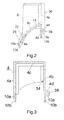
- Fig. 1 is an exploded perspective view of a door closing element 2 according to the invention (hereinafter referred to as closing element 2 called) shown, which forms the final element of a door of a household refrigerator in this example.
- closing element 2 the longitudinal, depth and height direction of the end element is indicated by a Cartesian coordinate system with the axes X, Y and Z.
- the end element 2 is designed in several parts and has at least two mutually corresponding, joinable profile elements 4, 6, which form in an assembled state, a total of the end element 2 forming profile structure unit.
- the one in which Fig. 1 lower profile element forms a connectable to a door edge of a door body base profile 4; and the other, in the Fig.
- the closure element 2 forms a connectable to the base profile 4 panel profile 6, which disguised in the assembled state, at least a portion of the base section 4.
- the closure element 2 has a strip-like, elongated shape.
- the total length of the closing element 2 in the longitudinal direction X preferably corresponds to the width of the door or of the door body to which or it should be connected later.
- the end member 2 is formed as an upper door edge termination. In another embodiment, however, it could also be designed as a lower door edge closure element.
- Both the base profile 4 and the trim profile 6 are each made of a thermoplastic material in an injection molding process. Both plastic materials are of the same type of material (or at least compatible with each other) and ultrasonically weldable, so that the profile elements 4, 6, as will be explained in more detail below, can be welded together.
- the base profile 4 are made of an opaque and the trim profile 6 made of a transparent thermoplastic material of the same plastic type.
- the trim profile 6 can also be made completely (or partially) from a translucent or opaque material or plastic material.
- the base profile 4 is half-shell-like or cap-shaped and adapted to be plugged onto a door edge and secured thereto. At its side portions it has in each case an accessible from its top insertion opening 8 for a pivot pin of a door hinge, or other means for connection to a door hinge mechanism, so that the closing element 2 is suitable both for doors in which the door pivot axis on the left side of the door lie as well as for those in which the pivot axis is located on the right side of the door.
- the unnecessary insertion opening 8 can be covered by a cap or the like.
- the base profile 4 also has an open hollow profile cross-section, which in the figure after Fig. 1 is open at the bottom.
- a sectional view along the plane II-II in Fig. 1 shows, has the cross-section of the base profile 4 in this area in the broadest sense, the shape of an inverted "U" with different lengths profile legs, which form a front wall 4a, a rear wall 4b and an intermediate upper wall 4c. 4c is in the in Fig. 2
- a sectional view taken along the plane III-III in Fig. 1 shows has the cross section essentially the shape of an approximately symmetrical, inverted "U".
- the lower edge regions of the base profile 4 are associated with a door edge and connectable to this.
- the profile contour of the edge regions or edges in this case corresponds substantially to the contour or profile contour of the associated door edge or the door edge of the usual manner forming sheets, plastic plates or door profiles.
- the base profile 4 at its lower edge door edge connection elements which may be configured, for example in the form of grooves 10a, grooves, claw-shaped areas, contact surfaces 10b, etc. and correspond correspondingly with the edge of the door.
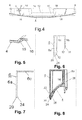
- Fig. 4 shows a frontal view of the base profile 4
- the recess 12 or this window extends over the entire depth of the base profile 4 in this area (see Fig. 1
- Beveled or curved side walls 14 surround the recess 12 in this case on three sides, so that the free passage cross section of the visible window-like recess 12 from the back extended to the front of the basic profile 4 out.
- Fig. 5 is a schematic sectional view taken along the plane VV in Fig. 4 shown.
- the base profile 4 has at a left and right side edge of a front portion 16 each have a groove 15th
- the trim profile 6 is also half-shell-like or trough or cap-shaped.
- Fig. 6 shows a section along the plane VI-VI in Fig. 1 represents, has the trim profile 6 in a central, the recess 12 and adjacent wall portions of the base profile 4 associated area a downwardly open hollow profile cross section, which has approximately the shape of an inverted "U"', with a front and rear wall 6a, 6b and a intermediate horizontal wall 6c.
- this U-shaped cross-section merges into a substantially L-shaped cross section, as shown in FIG Fig. 7 which shows a section along the plane VII-VII in Fig. 1 shows.
- the trim profile 6 is in the in Fig. 1 indicated by a large arrow direction, with its open side down, attachable to the back and corresponding receiving areas of the base profile 4. In the assembled or assembled with the base profile 4 state, the trim profile 6 completely covers the area of the viewing window or the recess 12.
- the trim profile 6 extends here also over lateral edges of the viewing window or the recess 12 across the adjacent front portions 16 and ceiling portions 18 of the base profile 4.
- rear portions of the trim profile 6 also extended beyond rear portions of the base profile 4 away. Parts of the cladding profile 6 therefore form part of the front, top and back of the final element 2 composed of the base profile 4 and the cladding profile 6.
- Fig. 8 shows a schematic sectional view along the in Fig. 1 and 4
- the trim profile 6 together with the base profile 6 is a substantially completely closed hollow profile cross-section, the extends over the entire recess 12 and laterally immediately adjacent areas away.
- the door edge closure element is particularly torsionally rigid and strong, and it can therefore be used profile elements with comparatively thin wall thicknesses, which also allows material savings. If a transparent or translucent cladding profile 6 is used, this forms a transparent "box" in the region of the viewing window or recess 12 due to its previously described profile cross-sectional shape.
- both profiles 4, 6 have guiding and positioning means for precisely matching these profile elements.
- the guiding and positioning means may in particular be mutually corresponding plug connections, for example in the form of spring and groove-like elements or regions or also pins, pins, tongues which can be inserted into correspondingly fitting openings or recesses, or in order other, in at least one direction producing a positive connection elements.
- These leadership and Positioning means can simultaneously serve as reinforcing elements for the thus assembled end element 2 and contribute, for example, to increase its bending and / or torsional rigidity and strength.
- a spring 24 of a laterally adjoining the lower edge 20, L-shaped downwardly angled region (see also 6 and 7 ) is inserted into a provided adjacent to the projection 22, corresponding groove 26 of the base section 4.
- the rear lower edge 28 of the wall 6a of the trim profile 6 rests on either the top of a rear portion of the central wall 14 or is at a small distance thereto, or has a similar tongue and groove arrangement as at the front edge 20.
- Die Side edges 6a1 of the front wall 6a of the trim profile 6 stuck with a spring (not shown) in the grooves 15 (see Fig. 1 and 3 ).
- side edges 6b1 of the rear wall 6b of the trim profile 6 are stuck in corresponding side grooves 30 (see FIG Fig. 1 ) on the back of the base profile 4.
- the side edges 6a1 and 6b1 are due to the shape of the grooves 15, 30, and the shape side edges 6a1, 6b1 itself, in the depth direction Y positively secured (see also Fig. 1 ).
- the base profile 4 and the trim profile 6 on connecting means. These connecting means are preferably formed integrally with these two profile elements 4, 6.
- the trim profile 6 has at its front and rear edge a plurality of integral, tongue-like tabs 32 which in corresponding slots 34 (see Fig. 1 and 3 ) in the basic profile 4 can be inserted.
- the tabs 32 and slots 34 also serve as guiding and positioning aids.
- a single slot 34 is shown in a diagrammatically cut-out area, as the slot 34 is concealed in the groove 26 (see FIG Fig. 2 ) lies.
- the length of these tabs 32 in the insertion direction is chosen so that they protrude slightly on the other side again from the base profile 4.
- these tabs 32 can then be welded to the material of the base profile 4 or at least be deformed so that they form a positive connection.
- the base profile 4 and the trim profile 6 are thus permanently connected to each other.
- the base profile 4 and the trim profile 6 on other Welded areas or interconnected by other suitable connection means, such as a latching connection, adhesive, etc.
- the base profile 4 and the trim profile 6 of this embodiment form in a joined state, at least at a front region and at the top of the end element 2 a flush outer contour.
- the profile contour of the base profile 4 is formed in the areas 16 and 18 at least corresponding to the respective wall thickness and the outer contour of the trim profile 6 of the desired outer contour of the finished closure element 2 offset inwardly or stepped (see Fig. 1 and 4 ).
- the depth of the gradations is partially slightly larger than the wall thickness of the trim profile 6 at the corresponding location, so that in these areas between the inner surface of the trim profile 6 and the outer surface of the base section 4 remains a small gap.
- Fig. 9 shows a schematic perspective rear view of the end element 2 of Fig. 1
- the rear wall 4b of the base profile 4 of lateral, rear profile edge portions 36 and a lower, rear edge 38 (see also FIGS. 2 and 3 ) of the same over a step 4d away in the depth direction Y back and forms over a majority of the back of the closing element 2 extending recess.
- the profile edge regions 36 and the edge 38 lie in this embodiment of a plane.
- the door closure element 2 according to the invention with its base profile 4 and trim profile 6 can be provided in the context of a door-end element sets, which can be used in a manufacturing process of substantially similar shaped household appliance doors in at least two different door variants, wherein the first variant has a first external appearance and the second variant has a second external appearance, which differs from the first external appearance.
- this set is used in a process for the production of household appliances with such different door variants.
- the set according to the invention comprises for series production, for example, a multiplicity of uniformly and / or identically shaped base profiles 4 and a plurality of trim profiles 6 of at least a first and a second one Trim profile type.
- These cladding profile types are identically shaped at least in a region which forms a joining region for joining to the base profile 4 and have a different external appearance.
- the first trim profile type is injection molded from an opaque thermoplastic material and the second type is a transparent one.
- these two panel profile types are completely identically shaped, so that the same injection mold or the same shape injection molds can be used for their production, and for example, only the plastic material or its properties must be varied.
- FIG. 10 is a schematic perspective view of an inventive household appliance in the form of a refrigerator 40 is shown.
- the refrigerator 40 has a case body 42 having a front opening and a door frame formed here from a front portion of the case body 42.
- a door 44 is pivotally mounted by means of a hinge member 45.
- the hinge member 45 has a pivot pin which in the insertion opening 8 (see, eg Fig. 1 ) of the closing element 2 can be inserted.
- the door 44 has a door body 46, the upper edge of which is provided with a door edge closing element 2 according to the invention, which extends over the entire width of the door 44.
- the height of the door 44 including the closing element 2 corresponds in this example substantially the height of the housing body.
- the width of the door 44 substantially corresponds to the width of the housing body 42.
- the base profile 4 of the end element 2 is made of an opaque plastic material, while the trim profile 6 is made of a transparent plastic material.
- the closing element 2 also has a central viewing window or a recess 12.
- the cladding profile 6 clad the viewing window 12 and also extends beyond even adjacent areas of the base profile 4. In the area of the viewing window 12, the cladding profile 6 simultaneously acts as a disc for the viewing window 12th
- a control panel 48 Arranged on an upper, central front area of the door frame or housing body 42 is a control panel 48 with device function and operating elements 50, which are, for example, an ON / OFF switch, operating status indicators (eg lights or displays), adjustment elements and the like can act.
- these elements 50 are behind the Viewing window 12 and are due to the transparency of the trim profile 6 well in the closed state of the door 44 well visible from outside through the viewing window 12 and located in the viewing window 12 area of the trim profile 6 therethrough or recognizable.
- a method according to the invention for producing refrigerators 40 with essentially identically shaped doors 44 in two different door variants, wherein the first variant has a first external appearance and the second variant has a second external appearance which differs from the first external appearance, will now be described. and a method according to the invention for producing such doors 44 by means of a door trim set according to the invention will be described.
- the respective refrigerators 40 on which these doors 44 are later mounted, in turn have a housing body 42 with a door frame, on which the respective associated door 44 is pivotally storable.
- the door body 46 used for producing the first and second door variant are uniform or substantially identical in shape, but it is basically sufficient that those door edge areas where the base section 4 is mounted, identical or substantially identical ,
- a uniform or identically shaped base profile 4 is provided in each case, but this provision need not be made simultaneously or at the same location.
- the door 44 is then pivotally attached to the housing body 42 and its door frame.
- the steps of providing the base profile 4 and the trim profile 6 can take place simultaneously, successively or in a different order and in particular the invention is not limited to a particular order in this regard.
- the method according to the invention can also have additional steps or intermediate steps for the respective door variant or the respective domestic appliance (here: refrigerator 40), for example for attaching sealing elements to the door 44 or the closing element 2, or e.g. for foaming the door body 46 and / or the closing element 2 with an insulating foam material.
- the number of required basic profiles 4 and trim profiles 6 (corresponding to the respective trim profile types) is to be matched to the number of doors or household appliances to be manufactured.
- connection of the closing element 2 was made to the edge of the door exclusively on the base profile 4, the invention is not limited to such a variant.
- the trim profile 6, depending on its shape and correspondingly corresponding shape of the base profile 4 have areas that are designed to be connected to the edge of the door.
- the inside of the viewing window 12 located in the substantially closed hollow profile cross-section can also be provided means for attaching device functional elements and / or device controls on which or in which then these functional or operating elements are to be arranged. If, for example, a touch control element is used as the control element, and if this is arranged close enough to a front inner surface of the trim profile 6 (or of the basic profile 4) from inside, then it can be replaced by the trim profile 6 (or the basic profile 4). be served away. Such operability can also be achieved if the operating element is arranged, for example, in an externally accessible opening of the trim profile 6 (or the basic profile 4).
- the terminating element 2 can also be open on its rear side, at least in some areas, so that, for example, a device-functional element and / or device operating element or a control panel 50 or the like arranged in the housing element 42 of the household appliance projects into the terminating element 2.
- decorative elements e.g. Adhesive sheets or the like, be attached, which are visible from the outside.
- decorative elements can also be attached to those areas of the base profile 4, over which the transparent or translucent trim profile 6 extends away and which are visible from the outside.
- a covering profile 6 or basic profile 4 can be produced, which integrally has both opaque and transparent or translucent areas.
- the basic profile 4 can basically be provided in different, but preferably equally shaped variants, a different external Appearance.
- the base profile 4 and the trim profile 6 can also be made of other suitable materials or combined with these.
Landscapes
- Engineering & Computer Science (AREA)
- Chemical & Material Sciences (AREA)
- Combustion & Propulsion (AREA)
- Physics & Mathematics (AREA)
- Mechanical Engineering (AREA)
- Thermal Sciences (AREA)
- General Engineering & Computer Science (AREA)
- Refrigerator Housings (AREA)
Abstract
Description
Die vorliegende Erfindung betrifft ein Türrand-Abschlusselement einer Haushaltsgeräte-Tür, insbesondere der Tür eines Kältegerätes; ferner betrifft die Erfindung eine Haushaltsgeräte-Tür, ein Haushaltsgerät sowie ein Tür-Abschlusselemente-Set mit einem solchen Türrand-Abschlusselement; Darüber hinaus betrifft die Erfindung ein Verfahren zur Herstellung von im Wesentlichen gleichartig geformten Haushaltsgeräte-Türen mit einem solchen Türrand-Abschlusselement, sowie ein Verfahren zur Herstellung von Haushaltsgeräten mit derartigen Türen.The present invention relates to a door edge closure element of a household appliance door, in particular the door of a refrigerator; Furthermore, the invention relates to a household appliance door, a household appliance and a door trim elements set with such a door edge closure element; Moreover, the invention relates to a method for producing substantially identically shaped household appliance doors with such a door edge terminating element, as well as a method for producing household appliances with such doors.
Aus der
Obwohl sich mit diesem vorbekannten Türrand-Abschlusselement bereits diverse unterschiedliche Erscheinungsbilder des Abschlusselementes und der Tür und des Kältegerätes, in welches dieses Abschlusselement integriert wird, realisieren lassen, so hat es sich doch gezeigt, dass sich mit dieser Technik nur eine relativ begrenzte Typenvielfalt und Formenvielfalt von Türrand-Abschlusselementen sowie entsprechenden Türen und Haushaltsgeräten mit unterschiedlichen Erscheinungsbilder rationell herstellen lassen. Darüber hinaus ergeben sich aufgrund der beschriebenen Bauweise des vorbekannten Türrand-Abschlusselementes bauliche und konstruktive Beschränkungen, die verhindern, dass das Türrand-Abschlusselement für optionale Zusatzkomponenten oder Zusatzfunktionen der zugehörigen Tür bzw. des Haushaltsgerätes genutzt werden kann. Besonders in der Serienproduktion von Haushaltsgeräten mit sehr großen Stückzahlen ist es jedoch wichtig, unterschiedliche Erscheinungsbilder und eine große Typenvielfalt mit einem möglichst geringen Aufwand an Material, Werkzeugen und Fertigungsmitteln produzieren zu können.Although it is already possible to realize various different appearances of the closing element and of the door and of the refrigerator into which this terminating element is integrated with this prior art door edge terminating element, it has been shown that only a relatively limited variety of types and shapes are possible with this technology of door edge trim elements and corresponding doors and household appliances with different appearances rationally produce. In addition, due to the described construction of the known door edge closure element structural and constructive limitations, prevent the door edge termination element for optional additional components or additional functions of the associated door or the household appliance can be used. Especially in mass production of household appliances with very large quantities, however, it is important to be able to produce different appearances and a large variety of types with the least possible effort on material, tools and tools.
Der Erfindung liegt daher die Aufgabe beziehungsweise das technische Problem zugrunde, ein verbessertes Türrand-Abschlusselement einer Haushaltsgeräte-Tür, insbesondere der Tür eines Kältegerätes; zu schaffen, das auf konstruktiv einfach und effektive Art und Weise und mit einfachen fertigungstechnischen Mitteln in unterschiedlichsten Erscheinungsbildern und Varianten hergestellt werden kann, und welches bei Bedarf auch für optionale Zusatzkomponenten oder Zusatzfunktionen der zugehörigen Tür bzw. des Haushaltsgerätes genutzt werden kann; ferner sollen eine Haushaltsgeräte-Tür, ein Haushaltsgerät und ein Tür-Abschlusselemente-Set mit einem solchen Türrand-Abschlusselement angegeben werden; überdies soll ein besonders geeignetes Verfahren zur Herstellung von im Wesentlichen gleichartig geformten Haushaltsgeräte-Türen sowie eines Haushaltsgerätes mit mindestens zwei unterschiedlichen Tür-Varianten, unter Verwendung eines solchen Tür-Abschlusselementes geschaffen werden.The invention is therefore based on the object or the technical problem, an improved door edge closure element of a household appliance door, in particular the door of a refrigerator; to create, which can be produced in a structurally simple and effective manner and with simple production engineering means in a variety of appearances and variants, and which can be used if necessary for optional additional components or additional functions of the associated door or the household appliance; Furthermore, a household appliance door, a household appliance and a door trim elements set are to be specified with such a door edge closure element; Moreover, a particularly suitable method for producing substantially identically shaped household appliance doors and a household appliance with at least two different door variants, using such a door closure element to be created.
Diese Aufgabe wird gemäß einem ersten Aspekt gelöst durch ein Türrand-Abschlusselement mit den Merkmalen des Anspruchs 1.This object is achieved according to a first aspect by a door edge closure element having the features of claim 1.
Dieses Türrand-Abschlusselement einer Haushaltsgeräte-Tür, insbesondere der Tür eines Kältegerätes, ist dadurch gekennzeichnet, dass es mehrteilig ausgebildet ist und mindestens zwei miteinander korrespondierende, zusammenfügbare Profil-Elemente aufweist, die in einem zusammengefügten Zustand eine die Gesamtheit des Türrand-Abschlusselements formende Profilstruktur-Einheit bilden; und dass das eine Profil-Element ein mit einem Türrand eines Türkörpers verbindbares Grundprofil und das andere Profil-Element mindestens ein mit dem Grundprofil verbindbares Verkleidungsprofil bildet, welches zumindest einen Teilbereich des Grundprofils verkleidet.This door edge closure element of a household appliance door, in particular the door of a refrigerator, is characterized in that it is designed in several parts and has at least two mutually corresponding, joinable profile elements, which in an assembled state, the entirety of the door edge-closing element forming profile structure Unit form; and that the one profile element is a basic profile connectable to a door edge of a door body and the other profile element is at least one connectable to the base profile Cladding profile forms, which disguises at least a portion of the basic profile.
Bei der erfindungsgemäßen Lösung sind also zwei oder mindestens zwei Profil-Elemente vorhanden, die zusammen erst das Türrand-Abschlusselement und dessen Gesamt-Profilstruktur ausbilden. Da eines dieser Profil-Elemente ein Verkleidungsprofil ist, übernimmt es nicht nur strukturelle Funktionen im Gesamtverbund mit dem anderen Profil-Element, d.h. dem Grundprofil, sondern kann gleichzeitig dazu dienen, das äußere Erscheinungsbild der Gesamteinheit des Türrand-Abschlusselement maßgeblich zu beeinflussen. Grundsätzlich ist es dadurch möglich, mit einem jeweils gleichen Grundprofil und diversen Verkleidungsprofilen, die jeweils gleich oder im Wesentlichen gleich geformt sind, aber ein unterschiedliches äußeres Erscheinungsbild besitzen, das äußere Erscheinungsbild des gesamten Türrand-Abschlusselementes maßgeblich zu beeinflussen bzw. bei Bedarf zu variieren. "Im Wesentlichen gleich geformte" Verkleidungsprofile bedeutet, dass diese Profile zumindest in einem Bereich, welcher einen Füge-Bereich zum Zusammenfügen mit dem Grundprofil bildet, identisch geformt sind, die anderen Bereiche des Profils aber durchaus unterschiedliche Formen oder Detailformen aufweisen können. Dies gestattet es zum Beispiel, für den Grundkörper und für den oder die Verkleidungskörper jeweils nur ein einzelnes Formwerkzeug zu verwenden - oder im Falle von "im Wesentlichen gleich geformten" Verkleidungsprofilen: im Wesentlichen gleichartige Formwerkzeuge, die sich jeweils nur geringfügig voneinander unterscheiden. Auf diese Weise können mit vergleichsweise sehr geringen Aufwendungen für Werkzeuge und Fertigungsmittel (z.B. Spritzgussformen) Türrand-Abschlusselemente in vielen unterschiedlichen Varianten bzw. mit unterschiedlichen äußeren Erscheinungsbildern produziert werden. Eine entsprechende Produktion ist besonders dann sehr effektiv und rationell realisierbar, wenn die Formen des Grundprofils und des Verkleidungsprofils unverändert beibehalten werden, jedoch diejenigen Materialeigenschaften dieser Profile variiert werden, welche das äußere Erscheinungsbild und/oder die optischen Eigenschaften beeinflussen. Dies ist besonders in der Serienproduktion von Haushaltsgeräten mit sehr großen Stückzahlen vorteilhaft. So kann zur Herstellung von im Wesentlichen gleichartig geformten Haushaltsgeräte-Türen in mindestens zwei unterschiedlichen Tür-Varianten mit unterschiedlichem äußeren Erscheinungsbild beispielsweise stets der gleiche Grundprofil-Typ verwendet und nur der Verkleidungsprofil-Typ bzw. dessen äußeres Erscheinungsbild variiert werden.In the solution according to the invention, therefore, two or at least two profile elements are present, which together form only the door edge closing element and its overall profile structure. Since one of these profile elements is a cladding profile, it not only takes over structural functions in the overall composite with the other profile element, ie the basic profile, but can also serve to significantly influence the appearance of the entire unit of the door edge closure element. In principle, this makes it possible, with a respective same basic profile and various cladding profiles, which are each the same or substantially the same shape, but have a different external appearance, to significantly influence the appearance of the entire door edge end element or to vary as needed. "Essentially the same shaped" cladding profiles means that these profiles are identically shaped at least in a region which forms a joining region for joining to the base profile, but the other regions of the profile may well have different shapes or detailed shapes. This makes it possible, for example, to use only a single molding tool for the base body and for the lining body or bodies - or in the case of "substantially identically shaped" lining profiles: essentially identical molding tools, which differ only slightly from each other. In this way, door edge trim elements can be produced in many different variants or with different external appearances with comparatively very low expenditures for tools and production means (eg injection molds). Corresponding production is very effective and rationally achievable, in particular, if the shapes of the base profile and of the trim profile are maintained unchanged, but the material properties of these profiles which influence the external appearance and / or the optical properties are varied. This is particularly advantageous in the mass production of household appliances with very large numbers. Thus, for example, the same basic profile type can always be used to produce essentially identically shaped household appliance doors in at least two different door variants with different external appearance, and only the profile profile type or its external appearance can be varied.
Darüber hinaus trägt der Aufbau des erfindungsgemäßen Türrand-Abschlusselementes aus mindestens zwei miteinander korrespondierenden, zusammenfügbaren Profil-Elementen dazu bei, die strukturellen und fertigungstechnischen Eigenschaften des Türrand-Abschlusselementes zu verbessern. Geht man davon aus, dass Türrand-Abschlusselemente für Haushaltsgeräte in der Regel aus Kunststoff und in einem Spritzgussverfahren hergestellt werden, so wird klar, dass bei einteiligen Türrand-Abschlusselementen, die in möglichst einfachen Spritzgussformen produziert werden sollen und leicht entformbar sein müssen, der Formenschatz relativ beschränkt ist. Werden hingegen mindestens zwei Profil-Elemente verwendet, so können diese selbst zwar in einfachen Spritzgussformen, z.B. ohne Hinterscheidungen, gefertigt werden, sie lassen sich jedoch bei Bedarf zu komplexeren Formen oder Formen mit einer größeren Formenvielfalt zusammenfügen. Einfache Spritzgussformen und eine gute Entformbarkeit setzen zudem in der Regel voraus, dass es sich bei dem herzustellenden Profil-Element um ein offenes Profilelement ohne oder mit möglichst wenigen Hinterschneidungen handelt. Die Festigkeitseigenschaften von offenen Profilen sind, z.B. hinsichtlich Biege- oder Torsionsbeanspruchungen, jedoch bekanntlich schlechter als bei geschlossenen Profilen. Bei der erfindungsgemäßen Lösung können die einzelnen (offenen) Profil-Elemente, die als solche einfach herstellbar und leicht entformbar sind, bei Bedarf jedoch zu einem geschlossenen Profil bzw. Hohlprofil zusammengefügt werden. Dadurch sind verbesserte Festigkeitseigenschaften des Türrand-Abschlusselementes bei gleichzeitig geringem Materialverbrauch und geringem Gewicht erzielbar. Zudem kann durch Verwendung der Profil-Elemente ein Türrand-Abschlusselement geschaffen werden, welches in seinem Inneren über vorbestimmte Hohlräume verfügt, die zur geschützten Aufnahme bzw. Anbringung von Geräte-Funktionselementen oder Geräte-Bedienelementen oder anderen Einbauteilen nutzbar sind. Da eines der Profil-Elemente als Verkleidungselement ausgebildet ist, kann es in der Art einer Kappe oder Klappe auch lösbar ausgestaltet werden, so dass etwaige Funktionselemente oder Geräte-Bedienelemente, z.B. zu Bedienungs- oder Wartungszwecken, leicht zugänglich sind.In addition, the construction of the door edge closure element according to the invention from at least two mutually corresponding, joinable profile elements contributes to improve the structural and manufacturing properties of the door edge termination element. Assuming that door edge trim elements for household appliances are usually made of plastic and in an injection molding process, it is clear that in one-piece door edge trim elements that are to be produced in the simplest possible injection molds and must be easily demoldable, the mold treasure is relatively limited. If, on the other hand, at least two profile elements are used, they may themselves be used in simple injection molds, e.g. without backgrounds, but they can be combined as needed to form more complex shapes or shapes with a greater variety of shapes. In addition, simple injection molds and good releasability generally require that the profile element to be produced is an open profile element without or with as few undercuts as possible. The strength properties of open profiles are, e.g. in terms of bending or torsional stresses, but known to be worse than closed profiles. In the solution according to the invention, however, the individual (open) profile elements, which as such are easy to manufacture and easily demouldable, can be joined together to form a closed profile or hollow profile if required. As a result, improved strength properties of the door edge end element with low material consumption and low weight can be achieved. In addition, by using the profile elements, a door edge closure element can be created, which has in its interior over predetermined cavities that can be used for protected recording or attachment of device-functional elements or device controls or other built-in parts. Since one of the profile elements is designed as a cladding element, it can also be made detachable in the manner of a cap or flap, so that any functional elements or device operating elements, e.g. for servicing or maintenance purposes.
Zusammenfassend schafft die erfindungsgemäße Lösung somit ein verbessertes Türrand-Abschlusselement einer Haushaltsgeräte-Tür, insbesondere der Tür eines Kältegerätes; das auf konstruktiv einfach und effektive Art und Weise und mit einfachen fertigungstechnischen Mitteln in unterschiedlichsten Erscheinungsbildern und Varianten rationell hergestellt werden kann, und welches bei Bedarf auch für optionale Zusatzkomponenten oder Zusatzfunktionen der zugehörigen Tür bzw. des Haushaltsgerätes nutzbar ist.In summary, the solution according to the invention thus provides an improved door edge closure element of a household appliance door, in particular the door of a refrigeration appliance; that in a structurally simple and effective way and with simple production engineering means in a variety of appearances and variants can be produced efficiently, and which can also be used for optional additional components or additional functions of the associated door or the household appliance if necessary.
Die der Erfindung zugrunde liegende Aufgabe wird gemäß einem zweiten Aspekt gelöst durch eine Haushaltsgeräte-Tür mit den Merkmalen des Anspruchs 19. Diese Haushaltsgeräte-Tür weist mindestens ein Türrand-Abschlusselement nach einem der Ansprüche 1 bis 18 auf.The object underlying the invention is achieved according to a second aspect by a household appliance door having the features of claim 19. This household appliance door has at least one door edge closure element according to one of claims 1 to 18.
Die der Erfindung zugrunde liegende Aufgabe wird gemäß einem dritten Aspekt gelöst durch ein Haushaltsgerät mit den Merkmalen des Anspruchs 20. Dieses Haushaltsgerät, insbesondere Kältegerät, weist einen Gehäusekörper mit einem Türrahmen und einer daran beweglich gelagerten Haushaltsgeräte-Tür nach Anspruch 19 auf.The object underlying the invention is achieved according to a third aspect by a household appliance having the features of
Mit der erfindungsgemäßen Haushaltsgeräte-Tür und dem erfindungsgemäßen Haushaltsgerät sind im Wesentlichen die gleichen Vorteile erzielbar, wie sie zuvor im Zusammenhang mit dem erfindungsgemäßen Türrand-Abschlusselement erläutert wurden.With the household appliance door according to the invention and the household appliance according to the invention substantially the same advantages can be achieved as they were previously explained in connection with the door edge closure element according to the invention.
Die der Erfindung zugrunde liegende Aufgabe wird gemäß einem vierten Aspekt gelöst durch ein Tür-Abschlusselemente-Set mit den Merkmalen des Anspruchs 23.The object underlying the invention is achieved according to a fourth aspect by a door-end element set with the features of claim 23.
Dieses Tür-Abschlusselemente-Set, mit mindestens einem Türrand-Abschlusselement nach einem der Ansprüche 1 bis 18 weist ein einheitlich geformtes Grundprofil und jeweils mindestens ein Verkleidungsprofil von mindestens einem ersten und einem zweiten Verkleidungsprofil-Typ auf. Die Verkleidungsprofile dieser Verkleidungsprofil-Typen sind zumindest in einem Bereich, welcher einen Füge-Bereich zum Zusammenfügen mit dem Grundprofil bildet, identisch geformt und besitzen ein unterschiedliches äußeres Erscheinungsbild.This door trim element set, with at least one door edge closure element according to one of claims 1 to 18, has a uniformly shaped base profile and in each case at least one trim profile of at least a first and a second trim profile type. The cladding profiles of these cladding profile types are identically shaped and have a different external appearance, at least in a region which forms a joining region for joining to the base profile.
"Set" ist hier nicht notwendiger Weise als ein einzelner Satz dieser entsprechend Komponenten zu verstehen, sondern ist insbesondere im Hinblick auf eine Serienproduktion auch im industriellen Größenmaßstab mit entsprechenden Stückzahlen der betreffenden Teile zu verstehen. Mit dem erfindungsgemäßen Tür-Abschlusselemente-Set sind im Wesentlichen die gleichen Vorteile erzielbar, wie sie zuvor im Zusammenhang mit dem erfindungsgemäßen Türrand-Abschlusselement erläutert wurden. Darüber hinaus ist das erfindungsgemäße Tür-Abschlusselemente-Set besonders vorteilhaft im Rahmen des nachfolgend genannten Herstellungsverfahrens verwendbar."Set" here is not necessarily to be understood as a single set of these corresponding components, but is to be understood in particular with regard to a series production on an industrial scale with corresponding quantities of the relevant parts. With the door trim elements set according to the invention Essentially, the same advantages can be achieved as they were previously explained in connection with the door edge closure element according to the invention. In addition, the door end element set according to the invention can be used particularly advantageously in the context of the production method mentioned below.
Die der Erfindung zugrunde liegende Aufgabe wird gemäß einem fünften Aspekt gelöst durch ein Verfahren nach Anspruch 25.The object underlying the invention is achieved according to a fifth aspect by a method according to claim 25.
Diese Verfahren zur Herstellung von im Wesentlichen gleichartig geformten Haushaltsgeräte-Türen in mindestens zwei unterschiedlichen Tür-Varianten, wobei die erste Variante ein erstes äußeres Erscheinungsbild und die zweite Variante ein zweites äußeres Erscheinungsbild besitzt, welches vom ersten äußeren Erscheinungsbild abweicht, mittels eines Tür-Abschlusselemente-Sets nach einem der Ansprüche 23, 24, umfasst folgende Schritte, jedoch nicht zwingender Weise in der nachfolgend angegebenen Reihenfolge:
- a) Für beide Tür-Varianten:
- a1) jeweils Bereitstellen eines einheitlich (bzw. identisch) geformten Grundprofils;
- b) Zur weiteren Herstellung der ersten Tür-Variante:
- b1) Bereitstellen eines Verkleidungsprofils des ersten Verkleidungsprofil-Typs; und
- b2) Zusammenfügen des Verkleidungsprofils mit dem betreffenden Grundprofil und dadurch Herstellung eines ersten Türrand-Abschlusselementes eines zweiten Türrand-Abschlusselement-Typs; und
- b3) Montieren dieses Türrand-Abschlusselementes an einen Türrand eines korrespondierenden Türkörpers und dadurch Herstellen einer Haushaltsgeräte-Tür der ersten Tür-Variante;
- c) Zur weiteren Herstellung der zweiten Tür-Variante:
- c1) Bereitstellen eines Verkleidungsprofils des zweiten Verkleidungsprofil-Typs; und
- c2) Zusammenfügen des Verkleidungsprofils mit dem betreffenden Grundprofil und dadurch Herstellung eines zweiten Türrand-Abschlusselementes eines zweiten Türrand-Abschlusselement-Typs; und
- c3) Montieren dieses Türrand-Abschlusselementes an einen Türrand eines korrespondierenden Türkörpers und dadurch Herstellen einer Haushaltsgeräte-Tür der zweiten Tür-Variante.
- a) For both door variants:
- a1) each providing a uniform (or identically) shaped base profile;
- b) For the further production of the first door variant:
- b1) providing a trim profile of the first trim profile type; and
- b2) joining the trim profile to the respective base profile and thereby producing a first door edge termination element of a second door edge termination element type; and
- b3) mounting this door edge terminating element to a door edge of a corresponding door body and thereby producing a household appliance door of the first door variant;
- c) For the further production of the second door variant:
- c1) providing a cladding profile of the second cladding profile type; and
- c2) joining the trim profile to the respective base profile and thereby producing a second door edge termination element of a second door edge termination element type; and
- c3) mounting this edge door closure element to a door edge of a corresponding door body and thereby producing a household appliance door of the second door variant.
Mit dem erfindungsgemäßen Verfahren sind im Wesentlichen die gleichen Vorteile erzielbar, wie sie zuvor im Zusammenhang mit dem erfindungsgemäßen Türrand-Abschlusselement erläutert wurden. Darüber hinaus trägt es wesentlich zur Rationalisierung und Kostenreduzierung bei der Grosserienproduktion von Haushaltsgeräte-Türen und Haushaltsgeräten mit solchen Türen bei.Essentially the same advantages can be achieved with the method according to the invention, as explained above in connection with the door edge closing element according to the invention. In addition, it contributes significantly to the rationalization and cost reduction in large-scale production of household appliance doors and household appliances with such doors.
Weitere bevorzugte und vorteilhafte Ausgestaltungsmerkmale der zuvor genannten erfindungsgemäßen Lösungen sind jeweils Gegenstand der zugehörigen abhängigen Ansprüche, die ihre Stütze in der nachfolgenden Beschreibung und den Zeichnungen finden.Further preferred and advantageous design features of the abovementioned solutions according to the invention are in each case the subject matter of the associated dependent claims, which find their support in the following description and the drawings.
Ein bevorzugtes Ausführungsbeispiel der Erfindung mit zusätzlichen Ausgestaltungsdetails und weiteren Vorteilen ist nachfolgend unter Bezugnahme auf die beigefügten Zeichnungen näher beschrieben und erläutert.A preferred embodiment of the invention with additional design details and other advantages is described below with reference to the accompanying drawings and explained.
Es zeigt:
- Fig. 1
- eine schematische perspektivische Explosionsansicht eines erfindungsgemäßen Tür-Abschlusselementes mit einem Grundprofil und einem Verkleidungsprofil;
- Fig. 2
- eine schematische Schnittansicht entlang der Ebene II-II in
Fig. 1 ; - Fig. 3
- eine schematische Schnittansicht entlang der Ebene III-III in
Fig. 1 ; - Fig. 4
- eine schematische Frontalansicht des Grundprofils des Tür- Abschlusselementes von
Fig. 1 ; - Fig. 5
- eine schematische Schnittansicht entlang der Ebene V-V in
Fig. 4 ; - Fig. 6
- eine schematische Schnittansicht entlang der Ebene VI-VI in
Fig. 1 ; - Fig. 7
- eine schematische Schnittansicht entlang der Ebene VII-VII in
Fig. 1 ; - Fig. 8
- eine schematische Schnittansicht entlang der mittleren Symmetrieebene des Tür-Abschlusselementes in einem zusammengefügten Zustand des Grundprofils und des Verkleidungsprofils;
- Fig.9
- eine schematische perspektivische Rückseitenansicht des Tür- Abschlusselementes von
Fig. 1 in einem zusammengefügten Zustand des Grundprofils und des Verkleidungsprofils; und - Fig.10
- eine schematische Perspektivansicht eines erfindungsgemäßen Kühlschranks mit dem Tür-Abschlusselement von
Fig. 1 .
- Fig. 1
- a schematic exploded perspective view of a door end element according to the invention with a base profile and a trim profile;
- Fig. 2
- a schematic sectional view taken along the plane II-II in
Fig. 1 ; - Fig. 3
- a schematic sectional view taken along the plane III-III in
Fig. 1 ; - Fig. 4
- a schematic frontal view of the basic profile of the door end element of
Fig. 1 ; - Fig. 5
- a schematic sectional view taken along the plane VV in
Fig. 4 ; - Fig. 6
- a schematic sectional view taken along the plane VI-VI in
Fig. 1 ; - Fig. 7
- a schematic sectional view taken along the plane VII-VII in
Fig. 1 ; - Fig. 8
- a schematic sectional view along the central plane of symmetry of the door-closing element in an assembled state of the base profile and the trim profile;
- Figure 9
- a schematic perspective rear view of the door end element of
Fig. 1 in an assembled state of the base profile and the trim profile; and - Figure 10
- a schematic perspective view of a refrigerator according to the invention with the door-closing element of
Fig. 1 ,
In der
Sowohl das Grundprofil 4 als auch das Verkleidungsprofil 6 sind jeweils aus einem thermoplastischen Kunststoffmaterial in einem Spritzgussverfahren hergestellt. Beide Kunststoffmaterialen sind vom gleichen Materialtyp (oder sind zumindest untereinander kompatibel) und ultraschall-verschweißbar, so dass die Profil-Elemente 4, 6, wie nachfolgend noch genauer erläutert werden wird, miteinander verschweißt werden können. In diesem Ausführungsbeispiel sind das Grundprofil 4 aus einem opaken und das Verkleidungsprofil 6 aus einem transparenten thermoplastischen Kunststoffmaterial des gleichen Kunststofftyps hergestellt. In einer weiteren Variante kann insbesondere das Verkleidungsprofil 6 jedoch auch vollständig (oder teilweise) aus einen transluzenten oder opaken Material bzw. Kunststoffmaterial hergestellt sein.Both the
Das Grundprofil 4 ist halbschalenartig oder kappenartig ausgebildet und dazu ausgelegt, auf einen Türrand aufgesteckt und an diesem befestigt zu werden. An seinen Seitenbereichen besitzt es jeweils eine von seiner Oberseite her zugängliche Einstecköffnung 8 für einen Gelenkzapfen eines Türgelenkes, oder andere Mitteln zum Verbinden mit einen Türgelenkmechanismus, so dass das Abschlusselement 2 sowohl für Türen geeignet ist, bei denen die Tür-Schwenkachse auf der linken Türseite liegen, als auch für solche, bei denen die Schwenkachse auf der rechten Türseite liegt. Die nicht benötigte Einstecköffnung 8 kann durch eine Kappe oder dergleichen abgedeckt werden. Das Grundprofil 4 weist ferner einen offenen Hohlprofilquerschnitt auf, der in der Abbildung nach
Wie in der
Wie aus der
In der
Das Verkleidungsprofil 6 ist ebenfalls halbschalenartig oder rinnen- oder kappenartig ausgebildet. Wie die
Das Verkleidungsprofil 6 ist in der in
Um das Zusammenfügen des Grundprofils 4 und des Verkleidungsprofils 6 bei einer Montage zu erleichtern, besitzen beide Profile 4, 6 Führungs- und Positionierungsmittel zum genauen Zusammenpassen dieser Profil-Elemente. Bei den Führungs- und Positionierungsmittel kann es sich insbesondere um miteinander korrespondierende Steckverbindungen handeln, zum Beispiel in Form von feder- und nut-artigen Elementen oder Bereichen oder auch Stiften, Zapfen, Zungen, die in entsprechend passende Öffnungen oder Aussparungen einsteckbar sind, oder um andere, in wenigstens einer Richtung eine formschlüssige Verbindung herstellende Elemente. Diese Führungs- und Positionierungsmittel können gleichzeitig als Verstärkungselemente für das so zusammengefügte Abschlusselement 2 dienen und dazu beitragen, z.B. dessen Biege- und/oder Torsionssteifigkeit und -Festigkeit zu erhöhen.In order to facilitate the assembly of the
Im vorliegenden Ausführungsbeispiel liegt der vordere untere Rand 20 des Verkleidungsprofils 6 auf einem vorderen Vorsprung 22 des Grundprofils 4 auf. Und eine Feder 24 eines sich seitlich an den unteren Rand 20 anschließenden, L-förmig nach unten abgewinkelten Bereichs (siehe auch
Ferner weisen das Grundprofil 4 und das Verkleidungsprofil 6 Verbindungsmittel auf. Diese Verbindungsmittel sind vorzugsweise integral mit diesen beiden Profil-Elementen 4, 6 ausgebildet. Im vorliegenden Fall besitzt das Verkleidungsprofil 6 an seinem vorderen und hinteren Rand mehrere integrale, zungenartige Laschen 32, die in korrespondierende Schlitze 34 (siehe
Das Grundprofil 4 und das Verkleidungsprofil 6 dieses Ausführungsbeispiels formen in einem zusammengefügten Zustand zumindest an einem Frontbereich und an der Oberseite des Abschlusselementes 2 eine bündige Außenkontur. Zu diesem Zweck ist die Profilkontur des Grundprofils 4 in den Bereichen 16 und 18 zumindest entsprechend der jeweiligen Wandstärke und der Außenkontur des Verkleidungsprofils 6 von der Soll-Außenkontur des fertigen Abschlusselementes 2 nach innen versetzt ausgebildet bzw. abgestuft (siehe
Das erfindungsgemäße Tür-Abschlusselement 2 mit seinem Grundprofil 4 und Verkleidungsprofil 6 kann im Rahmen eines Tür-Abschlusselemente-Sets bereit gestellt werden, welches in einem Herstellungsverfahren von im Wesentlichen gleichartig geformten Haushaltsgeräte-Türen in mindestens zwei unterschiedlichen Tür-Varianten verwendbar ist, wobei die erste Variante ein erstes äußeres Erscheinungsbild und die zweite Variante ein zweites äußeres Erscheinungsbild besitzt, welches vom ersten äußeren Erscheinungsbild abweicht. Ebenso ist dieses Set in einem Verfahren zur Herstellung von Haushaltsgeräten mit solchen unterschiedlichen Tür-Varianten verwendbar. Das erfindungsgemäße Set umfasst für eine Serienproduktion zum Beispiel eine Vielzahl einheitlich und/oder identisch geformter Grundprofile 4 und eine Vielzahl von Verkleidungsprofilen 6 von mindestens einem ersten und einem zweiten Verkleidungsprofil-Typ. Diese Verkleidungsprofil-Typen sind zumindest in einem Bereich, welcher einen Füge-Bereich zum Zusammenfügen mit dem Grundprofil 4 bildet, identisch geformt und besitzen ein unterschiedliches äußeres Erscheinungsbild. So ist der erste Verkleidungsprofil-Typ zum Beispiel aus einem opaken thermoplastischen Kunststoffmaterial im Spritzgussverfahren hergestellt und der zweite Typ aus einen transparenten. Es ist jedoch bevorzugt, dass diese zwei Verkleidungsprofil-Typen völlig identisch geformt sind, so dass zu Ihrer Herstellung die gleiche Spritzgussform oder gleich geformte Spritzgussformen verwendet werden können, und z.B. nur das Kunststoffmaterial bzw. dessen Eigenschaften variiert werden müssen.The
In der
An einem oberen, mittleren Frontbereich des Türrahmens bzw. Gehäusekörpers 42 ist eine Schalttafel 48 mit Geräte-Funktions- und -Bedienelementen 50 angeordnet, bei denen es sich zum Beispiel um einen AN/AUS-Schalter, Betriebszustandsanzeigen (z.B. Leuchten oder Displays), Einstellelemente und dergleichen handeln kann. Im geschlossenen Zustand der Tür 44 befinden sich diese Elemente 50 hinter dem Sichtfenster 12 und sind aufgrund der Transparenz des Verkleidungsprofils 6 auch im geschlossenen Zustand der Tür 44 gut von außen durch das Sichtfenster 12 und den im Sichtfenster 12 befindlichen Bereich des Verkleidungsprofils 6 hindurch einsehbar bzw. erkennbar.Arranged on an upper, central front area of the door frame or
Es wird nun ein erfindungsgemäßes Verfahren zur Herstellung von Kühlschränken 40 mit im Wesentlichen gleichartig geformten Türen 44 in zwei unterschiedlichen Tür-Varianten, wobei die erste Variante ein erstes äußeres Erscheinungsbild und die zweite Variante ein zweites äußeres Erscheinungsbild besitzt, welches vom ersten äußeren Erscheinungsbild abweicht, sowie ein erfindungsgemäßes Verfahren zur Herstellung von solchen Türen 44 mittels eines erfindungsgemäßen Tür-Abschlusselemente-Sets beschrieben werden.A method according to the invention for producing
Die jeweiligen Kühlschränke 40, an denen diese Türen 44 später montiert werden, besitzen wiederum einen Gehäusekörper 42 mit einem Türrahmen, an dem die jeweils zugeordnete Tür 44 schwenkbar lagerbar ist. Die zur Herstellung der ersten und zweiten Tür-Variante verwendeten Türkörper 46 sind einheitlich bzw. im Wesentlich identisch geformt, wobei es jedoch grundsätzlich ausreicht, dass diejenigen Türrand-Bereiche, an denen das Grundprofil 4 angebracht wird, identisch bzw. im Wesentlich identisch ausgebildet sind.The
Für beide Tür-Varianten wird jeweils ein einheitlich bzw. identisch geformtes Grundprofil 4 bereitgestellt, wobei diese Bereitstellung jedoch nicht gleichzeitig oder am gleichen Ort erfolgen muss.For both door variants, a uniform or identically shaped
Zur weiteren Herstellung der ersten Tür-Variante wird wie folgt vorgegangen:
- Es wird jeweils
ein Verkleidungsprofil 6 des ersten Verkleidungsprofil-Typs bereitgestellt.Die Verkleidungsprofile 6 dieses ersten Typs sind in diesem Beispiel aus einem opaken thermoplastischen Kunststoffmaterial hergestellt. Das opake Verkleidungsprofil 6 wirdmit einem Grundprofil 4 zusammengefügt und ultraschall-verschweißt. Dadurch wird ein Türrand-Abschlusselement 2 eines ersten Türrand-Abschlusselement-Typs geschaffen.Dieses Abschlusselement 2 wird dann an einen Türrand eines korrespondierenden Türkörpers 46 montiert und dadurch eine Tür 44 gemäß der ersten Tür-Variante geschaffen.
- In each case, a
trim profile 6 of the first trim profile type is provided. The trim profiles 6 of this first type are made in this example of an opaque thermoplastic material. - The opaque
trim profile 6 is assembled with abase profile 4 and ultrasonically welded. As a result, a dooredge closure element 2 of a first door edge closure element type is created. - This
closure element 2 is then mounted on a door edge of a corresponding door body 46, thereby creating adoor 44 according to the first door variant.
Die Tür 44 wird dann an dem Gehäusekörper 42 bzw. dessen Türrahmen schwenkbar befestigt.The
Zur weiteren Herstellung der zweiten Tür-Variante wird wie folgt vorgegangen:
- Es wird jeweils
ein Verkleidungsprofil 6 des zweiten Verkleidungsprofil-Typs bereitgestellt.Die Verkleidungsprofile 6 dieses zweiten Typs sind in diesem Beispiel aus einem transparenten thermoplastischen Kunststoffmaterial hergestellt. Das transparente Verkleidungsprofil 6 wird mit einem Grundprofil 4 (d.h. dem gleichem einheitlichen Grundprofil-Typ wie bei der ersten Tür-Variante) zusammengefügt und ultraschall-verschweißt. Dadurch wird ein Türrand-Abschlusselement 2 eines zweiten Türrand-Abschlusselement-Typs geschaffen.Dieses Abschlusselement 2 wird dann an einen Türrand eines korrespondierenden Türkörpers 46 montiert und dadurch eine Tür 44 gemäß der zweiten Tür-Variante geschaffen.Die Tür 44 wird dann andem Gehäusekörper 42 bzw. dessen Türrahmen schwenkbar befestigt.
- A
fairing profile 6 of the second fairing profile type is provided in each case. The cladding profiles 6 of this second type are made in this example of a transparent thermoplastic material. - The transparent
trim profile 6 is assembled with a base profile 4 (ie the same uniform basic profile type as in the first door variant) and ultrasonically welded. As a result, a dooredge closure element 2 of a second door edge closure element type is created. - This
end element 2 is then mounted on a door edge of a corresponding door body 46, thereby creating adoor 44 according to the second door variant. - The
door 44 is then pivotally attached to thehousing body 42 and its door frame.
Es ist selbstverständlich, dass beispielsweise die Schritte des Bereitstellens des Grundprofils 4 und des Verkleidungsprofils 6 gleichzeitig, nacheinander oder in unterschiedlicher Reihenfolge erfolgen können und die Erfindung insbesondere diesbezüglich nicht auf eine bestimmte Reihenfolge beschränkt ist. Auch kann das erfindungsgemäße Verfahren für die jeweilige Tür-Variante bzw. das jeweilige Haushaltsgerät (hier: Kühlschrank 40) zusätzliche Schritte bzw. Zwischenschritte aufweisen, zum Beispiel zur Anbringung von Dichtungselementen an der Tür 44 oder dem Abschlusselement 2, oder z.B. zum Ausschäumen des Türkörpers 46 und/oder des Abschlusselementes 2 mit einem isolierenden Schaumstoffmaterial. Die Anzahl der benötigten Grundprofile 4 und Verkleidungsprofile 6 (entsprechend den jeweiligen Verkleidungsprofil-Typen) ist auf die Anzahl der zu fertigenden Türen bzw. Haushaltsgeräte abzustimmen.It goes without saying that, for example, the steps of providing the
Die Erfindung ist nicht auf das obige Ausführungsbeispiel beschränkt. Im Rahmen des Schutzumfangs der beigefügten Ansprüche sind auch andere Ausführungsformen realisierbar.The invention is not limited to the above embodiment. Within the scope of the appended claims, other embodiments may be practiced.
Obwohl in dem obigen Ausführungsbeispiel die Verbindung des Abschlusselementes 2 zum Türrand ausschließlich über das Grundprofil 4 hergestellt wurde, ist die Erfindung nicht auf eine solche Variante beschränkt. Auch das Verkleidungsprofil 6 kann je nach seiner Formgebung und entsprechend korrespondierender Formgebung des Grundprofils 4 Bereiche aufweisen, die dazu ausgelegt sind, mit dem Türrand verbunden zu werden.Although in the above embodiment, the connection of the
In dem innerhalb des im Bereich des Sichtfensters 12 befindlichen, im Wesentlichen geschlossenen Hohl-Profilquerschnitt können auch Mittel zur Anbringung von Geräte-Funktionselementen und/oder Geräte-Bedienelementen vorgesehen sein, an denen oder in denen dann diese Funktions- oder Bedienelemente anzuordnen sind. Wird zum Beispiel ein Touch-Control-Element als Bedienelement verwendet, und wird dieses von innen her nahe genug an einer vorderen Innenfläche des Verkleidungsprofils 6 (oder auch des Grundprofils 4) angeordnet, so kann es durch das Verkleidungsprofil 6 (oder das Grundprofil 4) hinweg bedient werden. Eine solche Bedienbarkeit kann auch erzielt werden, falls das Bedienelement zum Beispiel in einer von außen zugänglichen Öffnung des Verkleidungsprofils 6 (oder des Grundprofils 4) angeordnet wird. Das Abschlusselement 2 kann an seiner Rückseite zumindest in Teilbereichen auch offen sein, so dass zum Beispiel ein am Gehäusekörper 42 des Haushaltsgerätes angeordnetes Geräte-Funktionselement und/oder Geräte-Bedienelement oder eine Schalttafel 50 oder dergleichen in das Abschlusselement 2 hinein ragt.In the inside of the
Bei Verwendung eines transparenten oder transluzenten Verkleidungsprofils 6 können am oder im Verkleidungsprofil 6 auch Dekorelemente, z.B. Klebefolien oder dergleichen, angebracht sein, die von außen sichtbar sind. Solche Dekorelemente können auch an denjenigen Bereichen des Grundprofils 4 angebracht sein, über die sich das transparente oder transluzenten Verkleidungsprofil 6 hinweg erstreckt und die von außen sichtbar sind. Zur Herstellung insbesondere des Verkleidungsprofils 6 in einer Spritzgussform lassen sich auch mehrere unterschiedliche Varianten des vorzugsweise gleichen Kunststofftyps verwenden; auf diese Weise ist z.B. ein Verkleidungsprofil 6 oder Grundprofil 4 herstellbar, welches integral sowohl opake als auch transparente oder transluzente Bereiche aufweist.When using a transparent or
Auch das Grundprofil 4 kann grundsätzlich in verschiedenen, vorzugsweise aber gleich geformten Varianten bereitgestellt werden, die ein unterschiedliches äußeres Erscheinungsbild aufweisen. Das Grundprofil 4 und das Verkleidungsprofil 6 können auch aus anderen geeigneten Werkstoffen hergestellt oder mit diesen kombiniert sein.Also, the
Bezugszeichen in den Ansprüchen, der Beschreibung und den Zeichnungen dienen lediglich dem besseren Verständnis der Erfindung und sollen den Schutzumfang nicht einschränken.Reference signs in the claims, the description and the drawings are only for the better understanding of the invention and are not intended to limit the scope.
- 22
- Tür-AbschlusselementDoor closing element
- 44
- Grundprofilbasic profile
- 4a4a
- Vordere Wand von 4Front wall of 4
- 4b4b
- Hintere Wand von 4Rear wall of 4
- 4c4c
- Zwischenwand von 4Partition of 4
- 4d4d
- Stufestep
- 66
- Verkleidungsprofiltrim profile
- 6a6a
- Vordere Wand von 6Front wall of 6
- 6a16a1
- Seitenränder von 6aMargins of 6a
- 6b6b
- Hintere Wand von 6Rear wall of 6
- 6b16b1
- Seitenränder von 6bMargins of 6b
- 6c6c
- Obere Wand von 6Upper wall of 6
- 88th
- Einstecköffnungen in 4Insertion openings in 4
- 10a10a
- Nutengroove
- 10b10b
- Anlageflächen von 4Contact surfaces of 4
- 1212
- Sichtfensterartige Aussparung in 4Viewing window-like recess in 4
- 1414
- Schräge SeitenwändeSloping side walls
- 1515
- Nutgroove
- 1616
- Frontbereiche von 4Front areas of 4
- 1818
- Deckenbereiche von 4Ceiling areas of 4
- 2020
- Vorderer unterer Rand von 6Front lower edge of 6
- 2222
- Vorsprung von 4Advantage of 4
- 2424
- Feder von 6Spring of 6
- 2626
- Nut von 4Groove of 4
- 2828
- Hinterer unterer Rand von 6bRear lower edge of 6b
- 3030
- Nuten in 4Grooves in 4
- 3232
- Laschentabs
- 3434
- Schlitzeslots
- 3636
- Seitliche, hintere Profilrandbereiche von 4Side, rear profile edge areas of 4
- 3838
- Unterer, hinterer Rand von 4Lower, rear edge of 4
- 4040
- Kühlschrankfridge
- 4242
- Gehäusekörperhousing body
- 4444
- Türdoor
- 4545
- Scharnierelementhinge element
- 4646
- Türkörperdoor body
- 4848
- SchalttafelSwitchboard
- 5050
- Geräte-Funktions- und -BedienelementeDevice function and operating elements
- XX
- Längsrichtunglongitudinal direction
- YY
- Tiefenrichtungdepth direction
- ZZ
- Höhenrichtungheight direction
Claims (27)
dadurch gekennzeichnet, dass
characterized in that
dadurch gekennzeichnet, dass
dieses als ein oberes Türrand-Abschlusselement (2) ausgebildet ist.Door edge closing element (2) according to claim 1,
characterized in that
this is formed as an upper door edge terminating element (2).
dadurch gekennzeichnet, dass
das Grundprofil (4) und das Verkleidungsprofil (6) aus miteinander verschweißbaren, insbesondere ultraschall-verschweißbaren, Kunststoffmaterialien hergestellt sind.Door edge termination element (2) according to claim 1 or 2,
characterized in that
the base profile (4) and the cladding profile (6) are made of plastic materials which can be welded together, in particular ultrasonically welded, to one another.
dadurch gekennzeichnet, dass
Grundprofil (4) und das Verkleidungsprofil (6) Verbindungsmittel (32, 34) zum unverlierbaren Verbinden dieser Profil-Elemente (4, 6) in einem zusammengefügten Zustand besitzen.Door edge closing element (2) according to one of the preceding claims,
characterized in that
Base profile (4) and the trim profile (6) connecting means (32, 34) for captively connecting these profile elements (4, 6) in an assembled state.
dadurch gekennzeichnet, dass
die Verbindungsmittel (32, 34) integral mit dem Grundprofil (4) und(oder dem Verkleidungsprofil (6) ausgebildet sind.Door edge closing element (2) according to claim 4,
characterized in that
the connecting means (32, 34) are formed integrally with the base profile (4) and (or the trim profile (6).
dadurch gekennzeichnet, dass
das Grundprofil (4) und das Verkleidungsprofil (6) Führungs- und Positionierungsmittel (15, 20, 22, 24, 26, 28, 30, 32, 34) zum genauen Zusammenpassen dieser beiden Profil-Elemente (4, 6) besitzen.Door edge closing element (2) according to one of the preceding claims,
characterized in that
the base profile (4) and the trim profile (6) have guiding and positioning means (15, 20, 22, 24, 26, 28, 30, 32, 34) for precisely matching these two profile elements (4, 6).
dadurch gekennzeichnet, dass
zumindest das Grundprofil (4) Türrand-Anschlusselemente (10a, 10b) zum passgenauen Anschließen des Grundprofils (4) an einen Türrand aufweist.Door edge closing element (2) according to one of the preceding claims,
characterized in that
at least the base profile (4) has door edge connection elements (10a, 10b) for accurately fitting the base profile (4) to a door edge.
dadurch gekennzeichnet, dass
das Grundprofil (4) und das Verkleidungsprofil (6) in einem zusammengefügten Zustand zumindest an einem Frontbereich des Türrand-Abschlusselementes (2), insbesondere an einem Frontbereich und einem oberen Bereich des Türrand-Abschlusselementes (2), eine bündige Außenkontur formen.Door edge closing element (2) according to one of the preceding claims,
characterized in that
the base profile (4) and the trim profile (6) in an assembled state form a flush outer contour at least on a front region of the door edge termination element (2), in particular on a front region and an upper region of the door edge termination element (2).
dadurch gekennzeichnet, dass
das Verkleidungsprofil (6) vollständig aus einen transparent Material hergestellt ist.Door edge closing element (2) according to claim 1,
characterized in that
the cladding profile (6) is made entirely of a transparent material.
dadurch gekennzeichnet, dass
das Verkleidungsprofil (2) aus einem transluzenten Material hergestellt ist.Door edge closing element (2) according to claim 1,
characterized in that
the cladding profile (2) is made of a translucent material.
dadurch gekennzeichnet, dass
das Verkleidungsprofil (6) aus einem opaken Material hergestellt ist.Door edge closing element (2) according to claim 1,
characterized in that
the cladding profile (6) is made of an opaque material.
dadurch gekennzeichnet, dass
das Grundprofil (4) halbschalenartig oder kappenartig ausgebildet und dazu ausgelegt ist, auf einen Türrand aufgesteckt und/oder an diesem befestigt zu werden.Door edge closing element (2) according to one of the preceding claims,
characterized in that
the base profile (4) has a half-shell-like or cap-like design and is designed to be plugged onto a door edge and / or fastened thereto.
dadurch gekennzeichnet, dass
das Verkleidungsprofil (6) halbschalenartig oder rinnen- oder kappenartig ausgebildet und auf einen korrespondierenden Aufnahmebereich (14, 15, 22, 26, 34; 30) des Grundprofils (4) aufsteckbar und/oder an diesem zu befestigen ist.Door edge closing element (2) according to one of the preceding claims,
characterized in that
the cladding profile (6) has a half-shell-like or channel-like or cap-like design and can be plugged onto and / or attached to a corresponding receiving area (14, 15, 22, 26, 34, 30) of the base profile (4).
dadurch gekennzeichnet, dass
das Verkleidungsprofil (6) einen offenen Hohlprofilquerschnitt besitzt und mit der offenen Seite dieses Hohlprofilquerschnitts auf das Grundprofil (4) aufsteckbar ist.Door edge closing element (2) according to one of the preceding claims,
characterized in that
the cladding profile (6) has an open hollow profile cross-section and with the open side of this hollow profile cross-section on the base profile (4) can be plugged.
dadurch gekennzeichnet, dass
bei Betrachtung des Türrand-Abschlusselementes (2) in Frontalansicht das Grundprofil (4) eine sichtfensterartige Aussparung (12) besitzt, welche sich über die gesamte Tiefe des Grundprofils (4) erstreckt; und das Verkleidungsprofil (6) in einem mit dem Grundprofil (4) zusammengefügten Zustand zumindest den Bereich des Sichtfensters (12) verkleidet.Door edge closing element (2) according to one of the preceding claims,
characterized in that
when viewing the door edge end element (2) in a front view, the base profile (4) has a view window-like recess (12) which extends over the entire depth of the base profile (4); and the cladding profile (6) in a state joined to the base profile (4) covers at least the region of the viewing window (12).
dadurch gekennzeichnet, dass
sich das Verkleidungsprofil (6) in einem mit dem Grundprofil (4) zusammengefügten Zustand zumindest über seitliche Ränder des Sichtfensters (12) hinweg über angrenzende Frontbereiche (16) und/oder obere Bereiche (18) des Grundprofils (4) erstreckt.Door edge closing element (2) according to one of the preceding claims,
characterized in that
the cladding profile (6) in a state joined to the base profile (4) extends at least over lateral edges of the viewing window (12) over adjacent front regions (16) and / or upper regions (18) of the base profile (4).
dadurch gekennzeichnet, dass
das Verkleidungsprofil (6) in einem mit dem Grundprofil (4) zusammengefügten Zustand im Bereich des Sichtfensters (12) zusammen mit dem Grundprofil (4) einen im Wesentlichen geschlossenen Hohl-Profilquerschnitt ausbildet.Door edge closing element (2) according to one of the preceding claims,
characterized in that
the trim profile (6) forms a substantially closed hollow profile cross-section in a state joined together with the base profile (4) in the region of the viewing window (12) together with the base profile (4).
dadurch gekennzeichnet, dass
innerhalb des im Bereich des Sichtfensters (12) befindlichen, im Wesentlichen geschlossenen Hohl-Profilquerschnitts Mittel zur Anbringung von Geräte-Funktionselementen oder Geräte-Bedienelementen vorgesehen sind.Door edge closing element (2) according to claim 17,
characterized in that
within the area of the viewing window (12) located, substantially closed hollow profile cross-section means for attaching device-functional elements or device controls are provided.
dadurch gekennzeichnet, dass
an dem Türrahmen ein Geräte-Funktionselement und/oder Geräte-Bedienelement (48; 50) angeordnet ist, welches sich im geschlossenen Zustand der Tür (44) hinter dem Türrand-Abschlusselement (2) befindet; und das Verkleidungsprofil (6) zumindest im Bereich des Geräte-Funktionselements und/oder Geräte-Bedienelements (48; 50) transparent oder transluzent ist.Household appliance (40) according to claim 20,
characterized in that
on the door frame, a device-functional element and / or device control element (48, 50) is arranged, which is in the closed state of the door (44) behind the door edge-closure element (2); and the trim profile (6) is transparent or translucent at least in the region of the device functional element and / or device control element (48; 50).
dadurch gekennzeichnet, dass
das Verkleidungsprofil (6) aus einem transparenten oder transluzenten Material hergestellt ist und im Bereich des Verkleidungsprofils (6) Geräte-Funktionselemente oder Geräte-Bedienelemente innerhalb des Türrand-Abschlusselementes (2) vorgesehen sind, die durch das transparente oder transluzente Verkleidungsprofil (6) hinweg bedienbar und/oder sichtbar sind.Household appliance (40) according to claim 20 or 21,
characterized in that
the cladding profile (6) is made of a transparent or translucent material and in the region of the cladding profile (6) device functional elements or device controls within the door edge termination element (2) are provided, passing through the transparent or translucent cladding profile (6) are operable and / or visible.
dadurch gekennzeichnet, dass
die Verkleidungsprofile (6) der mindestens zwei, ein unterschiedliches äußeres Erscheinungsbild besitzenden Verkleidungsprofil-Typen, im Wesentlichen völlig identisch geformt sind.Door end element set according to claim 23,
characterized in that
the cladding profiles (6) of the at least two cladding profile types having a different external appearance are substantially completely identically shaped.
dadurch gekennzeichnet, dass
die zur Herstellung der ersten und zweiten Tür-Variante verwendeten Türkörper (46) einheitlich geformt sind.Method according to claim 25,
characterized in that
the door bodies (46) used to make the first and second door variants are uniformly shaped.
Applications Claiming Priority (1)
| Application Number | Priority Date | Filing Date | Title |
|---|---|---|---|
| ES200702175A ES2339623B1 (en) | 2007-07-23 | 2007-07-23 | DOOR EDGE CLOSURE ELEMENT OF A DOMESTIC APPLIANCE DOOR. |
Publications (2)
| Publication Number | Publication Date |
|---|---|
| EP2023063A2 true EP2023063A2 (en) | 2009-02-11 |
| EP2023063A3 EP2023063A3 (en) | 2015-09-30 |
Family
ID=39817129
Family Applications (1)
| Application Number | Title | Priority Date | Filing Date |
|---|---|---|---|
| EP08104676.5A Withdrawn EP2023063A3 (en) | 2007-07-23 | 2008-07-09 | Door frame closing element of a household device door |
Country Status (2)
| Country | Link |
|---|---|
| EP (1) | EP2023063A3 (en) |
| ES (1) | ES2339623B1 (en) |
Cited By (3)
| Publication number | Priority date | Publication date | Assignee | Title |
|---|---|---|---|---|
| WO2011026817A2 (en) | 2009-09-01 | 2011-03-10 | Arcelik Anonim Sirketi | High - strength refrigerator door |
| DE102012012312A1 (en) * | 2012-05-18 | 2013-11-21 | Liebherr-Hausgeräte Ochsenhausen GmbH | Refrigerator or freezer has cooled inner space and door, by which cooled inner space is closable, where door has outer wall and inner wall, and outer wall is constructed in multiple portions and has two portions |
| US10240858B2 (en) * | 2014-12-25 | 2019-03-26 | Bsh Hausgeraete Gmbh | Home appliance having drawer-type movable container with a handle |
Citations (1)
| Publication number | Priority date | Publication date | Assignee | Title |
|---|---|---|---|---|
| DE10302797A1 (en) | 2003-01-24 | 2004-07-29 | BSH Bosch und Siemens Hausgeräte GmbH | Method by which data panel of refrigeration appliance with full height door may be viewed by using transparent section in door |
Family Cites Families (6)
| Publication number | Priority date | Publication date | Assignee | Title |
|---|---|---|---|---|
| JP3404224B2 (en) * | 1996-08-07 | 2003-05-06 | 松下冷機株式会社 | Refrigerator temperature controller |
| DE10051075A1 (en) * | 2000-10-14 | 2002-04-25 | Aeg Hausgeraete Gmbh | Procedure for manufacture of different operating panels for domestic apparatuses, especially cooking apparatuses, wash treatment machines, dish washers or cooling/freezing apparatuses |
| TR200300992T1 (en) * | 2001-02-13 | 2005-09-21 | Ar�El�K Anon�M ��Rket� | Household appliance. |
| DE20213208U1 (en) * | 2001-08-24 | 2003-01-09 | Thetford Corp | Fridge and refrigerator door assembly |
| JP2004044980A (en) * | 2002-07-15 | 2004-02-12 | Toshiba Corp | Refrigerator door |
| DE202005014382U1 (en) * | 2005-09-12 | 2005-11-10 | BSH Bosch und Siemens Hausgeräte GmbH | Refrigerator door has outer and inner walls surrounding hollow space onto which top and bottom end pieces are attached using a lip formed at the end of the main walls |
-
2007
- 2007-07-23 ES ES200702175A patent/ES2339623B1/en not_active Revoked
-
2008
- 2008-07-09 EP EP08104676.5A patent/EP2023063A3/en not_active Withdrawn
Patent Citations (1)
| Publication number | Priority date | Publication date | Assignee | Title |
|---|---|---|---|---|
| DE10302797A1 (en) | 2003-01-24 | 2004-07-29 | BSH Bosch und Siemens Hausgeräte GmbH | Method by which data panel of refrigeration appliance with full height door may be viewed by using transparent section in door |
Cited By (6)
| Publication number | Priority date | Publication date | Assignee | Title |
|---|---|---|---|---|
| WO2011026817A2 (en) | 2009-09-01 | 2011-03-10 | Arcelik Anonim Sirketi | High - strength refrigerator door |
| WO2011026817A3 (en) * | 2009-09-01 | 2011-07-14 | Arcelik Anonim Sirketi | High - strength refrigerator door |
| CN102483289A (en) * | 2009-09-01 | 2012-05-30 | 阿塞里克股份有限公司 | High -strength refrigerator door |
| CN102483289B (en) * | 2009-09-01 | 2015-02-18 | 阿塞里克股份有限公司 | High -strength refrigerator door |
| DE102012012312A1 (en) * | 2012-05-18 | 2013-11-21 | Liebherr-Hausgeräte Ochsenhausen GmbH | Refrigerator or freezer has cooled inner space and door, by which cooled inner space is closable, where door has outer wall and inner wall, and outer wall is constructed in multiple portions and has two portions |
| US10240858B2 (en) * | 2014-12-25 | 2019-03-26 | Bsh Hausgeraete Gmbh | Home appliance having drawer-type movable container with a handle |
Also Published As
| Publication number | Publication date |
|---|---|
| ES2339623B1 (en) | 2011-03-22 |
| EP2023063A3 (en) | 2015-09-30 |
| ES2339623A1 (en) | 2010-05-21 |
Similar Documents
| Publication | Publication Date | Title |
|---|---|---|
| EP2223030B1 (en) | Appliance door and household appliance having such a door | |
| DE102005037891B4 (en) | Door handle for a refrigerator | |
| EP1702187B1 (en) | Built-in refrigerating unit | |
| DE10018186B4 (en) | Vehicle door and method for its manufacture | |
| EP2059748B1 (en) | Built-in refrigerator with dispensing device | |
| EP2235451B1 (en) | Storage container for a refrigerating device | |
| EP1913318A1 (en) | Modular container for refrigerated products | |
| EP2467657B1 (en) | Door for a household appliance having a handle insert | |
| EP2023063A2 (en) | Door frame closing element of a household device door | |
| WO2011124446A2 (en) | Door shelf for a refrigerator | |
| DE60011949T2 (en) | Lock fitting of the type espagnolette fitting or the like | |
| EP2163840A2 (en) | Household refrigerating device with at least one door | |
| EP1926952B1 (en) | Door for a refrigerator | |
| DE602005002067T2 (en) | Door or window structure made of a metal profile bar | |
| EP2457039A2 (en) | Door for a heat-insulating housing | |
| DE10307536B4 (en) | Rectangular keypad bezel and method of making the same | |
| EP1576326A1 (en) | Refrigerator and door for a refrigerator | |
| DE10208063B4 (en) | Door racks for a refrigeration device | |
| DE102017002640A1 (en) | Window frame for a vehicle window pane | |
| WO2000001992A1 (en) | Storage compartment | |
| EP2311347A1 (en) | Closing element for closing a gap between built-in appliance and surrounding furniture | |
| WO2002081990A1 (en) | Storage container for refrigerators | |
| DE2029825A1 (en) | Profile element | |
| DE3447801A1 (en) | Box-shaped component for electrical switching and distribution installations | |
| DE2051282C3 (en) | Shell handle |
Legal Events
| Date | Code | Title | Description |
|---|---|---|---|
| PUAI | Public reference made under article 153(3) epc to a published international application that has entered the european phase |
Free format text: ORIGINAL CODE: 0009012 |
|
| AK | Designated contracting states |
Kind code of ref document: A2 Designated state(s): AT BE BG CH CY CZ DE DK EE ES FI FR GB GR HR HU IE IS IT LI LT LU LV MC MT NL NO PL PT RO SE SI SK TR |
|
| AX | Request for extension of the european patent |
Extension state: AL BA MK RS |
|
| RAP1 | Party data changed (applicant data changed or rights of an application transferred) |
Owner name: BSH HAUSGERAETE GMBH |
|
| PUAL | Search report despatched |
Free format text: ORIGINAL CODE: 0009013 |
|
| AK | Designated contracting states |
Kind code of ref document: A3 Designated state(s): AT BE BG CH CY CZ DE DK EE ES FI FR GB GR HR HU IE IS IT LI LT LU LV MC MT NL NO PL PT RO SE SI SK TR |
|
| AX | Request for extension of the european patent |
Extension state: AL BA MK RS |
|
| RIC1 | Information provided on ipc code assigned before grant |
Ipc: F25D 23/02 20060101AFI20150824BHEP |
|
| 17P | Request for examination filed |
Effective date: 20160330 |
|
| RBV | Designated contracting states (corrected) |
Designated state(s): AT BE BG CH CY CZ DE DK EE ES FI FR GB GR HR HU IE IS IT LI LT LU LV MC MT NL NO PL PT RO SE SI SK TR |
|
| AKX | Designation fees paid |
Designated state(s): AT BE BG CH CY CZ DE DK EE ES FI FR GB GR HR HU IE IS IT LI LT LU LV MC MT NL NO PL PT RO SE SI SK TR |
|
| AXX | Extension fees paid |
Extension state: AL Extension state: BA Extension state: RS Extension state: MK |
|
| 17Q | First examination report despatched |
Effective date: 20180301 |
|
| GRAP | Despatch of communication of intention to grant a patent |
Free format text: ORIGINAL CODE: EPIDOSNIGR1 |
|
| INTG | Intention to grant announced |
Effective date: 20180830 |
|
| STAA | Information on the status of an ep patent application or granted ep patent |
Free format text: STATUS: THE APPLICATION IS DEEMED TO BE WITHDRAWN |
|
| 18D | Application deemed to be withdrawn |
Effective date: 20190110 |