EP2020358A2 - Jack lift with lift arm - Google Patents
Jack lift with lift arm Download PDFInfo
- Publication number
- EP2020358A2 EP2020358A2 EP08009973A EP08009973A EP2020358A2 EP 2020358 A2 EP2020358 A2 EP 2020358A2 EP 08009973 A EP08009973 A EP 08009973A EP 08009973 A EP08009973 A EP 08009973A EP 2020358 A2 EP2020358 A2 EP 2020358A2
- Authority
- EP
- European Patent Office
- Prior art keywords
- load
- load roller
- rollers
- roller carrier
- truck according
- Prior art date
- Legal status (The legal status is an assumption and is not a legal conclusion. Google has not performed a legal analysis and makes no representation as to the accuracy of the status listed.)
- Granted
Links
Images


Classifications
-
- B—PERFORMING OPERATIONS; TRANSPORTING
- B62—LAND VEHICLES FOR TRAVELLING OTHERWISE THAN ON RAILS
- B62B—HAND-PROPELLED VEHICLES, e.g. HAND CARTS OR PERAMBULATORS; SLEDGES
- B62B3/00—Hand carts having more than one axis carrying transport wheels; Steering devices therefor; Equipment therefor
- B62B3/04—Hand carts having more than one axis carrying transport wheels; Steering devices therefor; Equipment therefor involving means for grappling or securing in place objects to be carried; Loading or unloading equipment
- B62B3/06—Hand carts having more than one axis carrying transport wheels; Steering devices therefor; Equipment therefor involving means for grappling or securing in place objects to be carried; Loading or unloading equipment for simply clearing the load from the ground
- B62B3/0612—Hand carts having more than one axis carrying transport wheels; Steering devices therefor; Equipment therefor involving means for grappling or securing in place objects to be carried; Loading or unloading equipment for simply clearing the load from the ground power operated
-
- B—PERFORMING OPERATIONS; TRANSPORTING
- B62—LAND VEHICLES FOR TRAVELLING OTHERWISE THAN ON RAILS
- B62B—HAND-PROPELLED VEHICLES, e.g. HAND CARTS OR PERAMBULATORS; SLEDGES
- B62B5/00—Accessories or details specially adapted for hand carts
- B62B5/02—Accessories or details specially adapted for hand carts providing for travelling up or down a flight of stairs
- B62B5/025—Accessories or details specially adapted for hand carts providing for travelling up or down a flight of stairs with gliding elements, e.g. skids
-
- B—PERFORMING OPERATIONS; TRANSPORTING
- B62—LAND VEHICLES FOR TRAVELLING OTHERWISE THAN ON RAILS
- B62B—HAND-PROPELLED VEHICLES, e.g. HAND CARTS OR PERAMBULATORS; SLEDGES
- B62B5/00—Accessories or details specially adapted for hand carts
- B62B5/02—Accessories or details specially adapted for hand carts providing for travelling up or down a flight of stairs
- B62B5/026—Accessories or details specially adapted for hand carts providing for travelling up or down a flight of stairs with spiders or adapted wheels
Definitions
- the invention relates to a pallet truck, in particular low-lift truck, with a drive part and a relative to the drive part vertically movable load part having load arms, which are supported by means of at least two load rollers having load roller device on a roadway, the load rollers are rotatably mounted in each case a load roller carrier which is rotatably mounted on a pivot arm, wherein the pivot arm for the vertical movement of the load arms is arranged relative to the drive part pivotally mounted on the load arm.
- a generic pallet truck in which the load arms by means of a respective load roller device having two load rollers, is supported on the road, is from the EP 1 077 169 A1 known.
- the two load rollers are here tandem and thus arranged in the longitudinal direction of the lift truck in a row. This results in a high space requirement of the load roller device in the longitudinal direction, which makes it difficult in particular the retraction of the lift truck in a querrien range, the load rollers must run over a floor board of the pallet.
- the present invention has for its object to provide a pallet truck of the type mentioned available with the larger obstacles can be run over and with the retraction in a transverse standing pallet is facilitated.
- the object is achieved in that the load rollers are laterally offset in the load roller carrier and arranged superimposed in the longitudinal direction.
- the load rollers in the load roller carrier are laterally offset arranged, whereby it is possible to arrange the axes of rotation of the load rollers such that the distance between the axes of rotation of the load rollers is less than the diameter of the load rollers.
- a superposition of the load rollers in the longitudinal direction allows and thus achieved a small space requirement of the load roller device in the longitudinal direction of the lift truck.
- the retraction of the lift truck is facilitated in a transverse range and also allows an enlarged pivoting range of the load roller device relative to the pivot arm, so that with the pallet truck according to the invention continue larger obstacles on the road can be safely and easily run over.
- the load roller device each has two load rollers and two load rollers are arranged in each load roller carrier
- the load roller carrier with at least one upwardly extending, arcuate contour is provided.
- the arcuate contour in this case forms a runner, which causes a pivoting of the load roller when driving over larger obstacles in the road, for example, a curb or a curb lowering, whereby the pallet truck according to the invention safely and easily overcome large obstacles and thus can overcome.
- the contour extends from a region near the ground to a region remote from the ground, which substantially corresponds to the height of the load rollers.
- the load roller support encloses the load rollers in both directions of travel, wherein the load roller carrier is provided for each direction of travel, each with an upwardly extending arcuate contour.
- At least one stop for limiting the pivoting movement of the load roller carrier relative to the pivot arm is provided on the load roller carrier.
- the stop can be formed with low construction costs according to a preferred embodiment of a arranged on the load roller carrier stop pin, which can be brought into operative connection with the pivot arm.
- At least one roller-shaped additional roller is provided, which is rotatably mounted in the load roller carrier in the area remote from the ground in front of the corresponding load roller.
- the additional role is expediently arranged at the upper end of the arcuate contour on the load roller carrier.
- a climbing aid formed by the additional role can be achieved with low construction costs for both directions.
- the pivot axis of the load roller carrier is arranged centrally in the swivel arm between the axes of rotation of the load rollers.
- the load roller device each has three load rollers, wherein in each load roller carrier three load rollers are arranged in a star shape.
- a star-shaped arrangement of three load rollers can also with the pallet truck according to the invention larger obstacles of the road, for example, a curb or a curb lowering safely and easily run over and thus overcome.
- the load roller carrier with the three star-shaped load rollers is in this case rotatably mounted in the swivel arm 360 °, so that at a larger obstacle whose height corresponds approximately to the diameter of the load rollers, the load roller carrier is pivoted when passing over the obstacle by 120 °, whereby the Override obstacle safely and easily and thus can be overcome.
- a simple construction is achievable in this case when the load roller carrier is provided substantially with a triangular contour, wherein the axes of rotation of the load rollers are arranged as an equilateral triangle. With such an arrangement of the load rollers at the tips of an equilateral triangle, a star-shaped arrangement of the three load rollers can be achieved in a simple manner.
- the axis of rotation of the load roller carrier in the swivel arm in this case according to a preferred embodiment of the invention of the axes of rotation of the castors in each case the same distance.
- a star-shaped arrangement of the load rollers can be achieved in a simple manner, wherein the load rollers each have an angle of 120 ° with respect to the axis of rotation of the load roller carrier. With such an arrangement of the load rollers larger obstacles in both directions can be overcome in a simple manner.
- the load roller carrier is provided with at least one filler body which at least partially surrounds the load rollers and is adapted to the contour of the load roller carrier.
- the fillers form deflectors with which jamming of smaller objects lying on the roadway, for example of stones, between the Load rollers and the load carrier are effectively avoided.
- the filler an additional mass generated that allow a smooth running of the load roller devices on the road despite the reduced distance of the axes of rotation of the load rollers and allow improved stability of the lift truck by a low center of gravity, especially on inclines and gradients and laterally inclined roads.
- the load arms are each designed to be open at the top in the area of the load roller device, a large pivot range of the load roller carriers can be permitted, and thus larger obstacles of the roadway can be overrun in a simple manner.
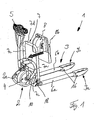
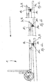
- FIG. 1 is an inventive, designed as a pallet truck pallet truck 1 with a drive part 2 and a load part 3 shown.
- the drive part 2 comprises a bow-shaped frame portion 2a, on which a traction drive unit 4, which comprises a drive wheel and a driving motor driving the driving wheel, is arranged steerable.
- the steering of the lift truck 1 is effected by means of a drawbar connected to the drive unit 4 4.
- the drive wheel of the drive unit 4 is here designed as a pneumatic tire drive wheel.
- For load part 3 includes two load arms 6a, 6b, with which loads, such as pallets, lattice boxes or small parts container can be added, lifted and transported.
- loads such as pallets, lattice boxes or small parts container
- a vertical strap section 7 is arranged on the load part 3, which is formed by lateral longitudinal braces 7a, 7b, a lower transverse bow 7c and an upper transverse bow 7d.
- the bow-shaped frame section 2a of the drive part 2 and the load part 3 formed by the load arms 6a, 6b and the strap section 7 is essentially formed by one-piece hollow profiles with a closed cross-section.
- the bracket portion 7 serves to receive a housing 8, which is provided with a battery compartment for a battery 8b and in which further electrical or electronic components of an electric drive system of the lift truck 1 are arranged.
- the load part 3 is arranged on the drive part 2 by means of a lever assembly formed by articulated levers 10 movable in the vertical direction.
- a no longer shown, designed for example as a hydraulic cylinder lifting device is provided, which is arranged between the drive part 2 and the load part 3 and generates a force acting on the load part 3 lifting movement.
- the load part 3 is supported by means of each load roller device 9a, 9b on a roadway, which are respectively arranged at the load-side ends of the load arms 6a, 6b. In the area of the load roller device 9a, 9b, the load arms 6a, 6b are open at the top.
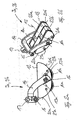
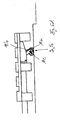
- FIGS. 2a and 2b a first embodiment of a load roller device 9a, 9b according to the invention is shown, wherein in the FIG. 2a a side view of the load roller device 9a, 9b is shown and the FIG. 2b a perspective view of the load roller device 9a, 9b shows.
- Each load roller device 9a, 9b has two load rollers 11a, 11b which are arranged one behind the other in the longitudinal direction and which are rotatably mounted in a load roller carrier 12 by means of a respective rotation axis 13a or 13b.
- the load roller carrier 12 is rotatably mounted on a bow-shaped pivot arm 14 by means of a rotation axis 15.
- the axis of rotation 15 is in this case arranged centrally with respect to the axes of rotation 13a, 13b.
- the pivot arm 14 is pivotally mounted on the corresponding load arm 6a and 6b by means of a pivot axis 16.
- On a further axis 17 of the pivot arm 14 is formed, for example, designed as a push rod rod 18 articulated, which is disposed within the load arms 6a, 6b and is in operative connection with the other end to the articulated lever 10.
- a lifting movement of the lifting device can thus be converted by means of the hinge lever 10 and the rods 18 in a pivoting movement of the pivot lever 14 and thus a vertical movement of the load rollers 11 a, 11 b, whereby the load part 3 can be raised or lowered relative to the drive part 2.
- the rods 18 can also be formed here as tie rods.
- the distance between the axes of rotation 13a, 13b of the load rollers 11a, 11b is less than the diameter of the load rollers 11a, 11b, so that the load rollers 11a, 11b - as shown in FIG. 2b is visible - laterally offset in the load roller carrier 12 and arranged superimposed in the longitudinal direction.
- the load roller carrier 12 encloses the load rollers 11a, 11b on the front side and the rear side in the longitudinal direction and is provided with an upwardly extending arcuate contour 20a, 20b on each side and thus for each direction of travel.
- the arcuate contour 20a, 20b extends from a lower region near the bottom to an upper region remote from the bottom, which substantially corresponds to the height of the load rollers 11a, 11b.
- a stop formed by two stop pins 21a, 21b is provided.
- the stop pins 21a, 21b are in this case arranged on a side plate of the load roller carrier 12 and reach during pivoting of the load roller carrier 12 with the pivot arm 14 in operative connection.
- packing 22a, 22b are arranged and fixed, which partially enclose the corresponding load roller 11a, 11b and are adapted to the contour of the load roller carrier 12.
- FIGS. 3a and 3b is a further embodiment of a load roller device according to the invention 9a, 9b shown, which is substantially in the FIGS. 2a, 2b shown load roller device 9a, 9b corresponds.
- the FIG. 3a shows here a view from above and the FIG. 3b a perspective view of the load roller device 9a, 9b.
- the load roller carrier 12 in which the two load rollers 11a, 11b as in the embodiment according to the FIGS. 2a and 2b laterally offset and arranged superimposed in the longitudinal direction is provided with roller-shaped additional rollers 25a, 25b, which are rotatably arranged in the load roller carrier 12 in the area remote from the floor.
- the additional roller 25a is in this case arranged in the upper region of the arcuate contour 20a and is located in the longitudinal direction in front of the load roller 11a.
- the additional roller 25b is located at the top of the arcuate contour 25b and is arranged in the longitudinal direction in front of the load roller 25b.
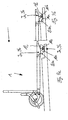
- FIGS. 4a to 4e is one with the load roller devices 9a, 9b according to the FIGS. 2a, 2b or 3a, 3b equipped lifting truck 1 shown when driving over a larger obstacle, such as a curb, which has a height of about 70mm, which substantially corresponds to the diameter of the load rollers 11a, 11b.
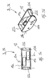
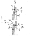
- FIGS. 5a to 5d a further embodiment of a load roller device 9a, 9b according to the invention is shown.
- pivot lever 14 which is pivotally mounted on the axis 16 on the load arm and on which on the axis 17, for example, designed as a push rod rod 18, a load roller support 12 is rotatably mounted about the rotation axis 15 by 360 °, at the three laterally offset and Superposed in the longitudinal direction arranged load rollers 11a, 11b and 11c are arranged in a star shape.
- the load roller 11a is here - as from the FIG. 5c can be seen, in which a plan view of the load roller device 9a, 9b is shown - mounted about a rotational axis 13a in the load roller carrier 12. Accordingly, the load roller 11b is rotatably mounted about a rotation axis 13b and the load roller 13c about a rotation axis 13c, wherein the distance the axes of rotation 13a and 13b between each other is less than the diameter of the load rollers 11a, 11b, 11c and thus the load rollers 11a, 11b and 11c are arranged superimposed. Seen in the longitudinal direction, the axis of rotation 13c is arranged centrally between the axes of rotation 13a and 13b.
- the distance of the rotation axis 13a from the rotation axis 13c is in this case selected such that the rotation axis 13a within the diameter of the load roller 11c and corresponding to the axis of rotation 13c within the diameter of the load roller 11a. Accordingly, the distance between the two rotation axes 13c and 13b is selected such that the axis of rotation 13c within the diameter of the load roller 11b and the axis of rotation 13b is within the diameter of the load roller 11c.
- the load roller 11a is superposed on the load rollers 11b and 11c
- the load roller 11b is superimposed on the load rollers 11a and 11c
- the load roller 11c is superimposed on the load rollers 11a and 11b.
- the load rollers 11a, 11b, 11c are here - as in the FIG. 5d is shown - arranged in a substantially triangular load roller carrier 12, wherein the axes of rotation 13a, 13b, 13c of the load rollers 11a, 11b, 11c are arranged at the tips of an equilateral triangle.
- the axis of rotation 15 of the load roller carrier 12 in the pivot arm 14 in this case has the same distance from the axes of rotation 13a, 13b and 13c. In this way it is achieved that the load rollers 11a, 11b, 11c are arranged with respect to the rotation axis 15 by a respective rotation angle of 120 °.
- fillers 22a, 22b and 22c can be provided, which partially enclose the corresponding load roller 11a, 11b and 11c and are adapted to the triangular contour of the load roller carrier 12.
- FIGS. 6a to 6d show one with load roller devices 9a, 9b according to the FIGS. 5a to 5d equipped lifting truck 1 when driving over a trained example as a curbside larger obstacle whose height corresponds to the diameter of the load rollers.
- the load roller carrier 12 is in this case opposite to in the FIG. 6a shown position in a rotated by a rotation angle of 120 ° position.
- a transverse pallet simply be driven under and transported.
- the lifting truck 1 according to the invention is particularly suitable for applications outside of warehouses and production facilities, where an uneven road surface is given, for example, on streets and squares, since by the load roller devices 9a, 9b invention in conjunction with a pneumatic tire driving drive unit having larger obstacles of the road For example, curbs and curbs lowering, whose height corresponds to the diameter of the load rollers or exceeds, can be overcome easily and safely.
Landscapes
- Engineering & Computer Science (AREA)
- Chemical & Material Sciences (AREA)
- Combustion & Propulsion (AREA)
- Transportation (AREA)
- Mechanical Engineering (AREA)
- Handcart (AREA)
Abstract
Description
Die Erfindung betrifft einen Hubwagen, insbesondere Niederhubwagen, mit einem Antriebsteil und einem relativ zum Antriebsteil vertikal bewegbaren Lastteil, das Lastarme aufweist, die mittels jeweils einer mindestens zwei Lastrollen aufweisenden Lastrolleneinrichtung auf einer Fahrbahn abgestützt sind, wobei die Lastrollen in jeweils einem Lastrollenträger drehbar gelagert sind, der an einem Schwenkarm drehbar gelagert ist, wobei der Schwenkarm zur vertikalen Bewegung der Lastarme relativ zum Antriebsteil schwenkbar an dem Lastarm angeordnet ist.The invention relates to a pallet truck, in particular low-lift truck, with a drive part and a relative to the drive part vertically movable load part having load arms, which are supported by means of at least two load rollers having load roller device on a roadway, the load rollers are rotatably mounted in each case a load roller carrier which is rotatably mounted on a pivot arm, wherein the pivot arm for the vertical movement of the load arms is arranged relative to the drive part pivotally mounted on the load arm.
Ein gattungsgemäßer Hubwagen, bei dem die Lastarme mittels jeweils einer Lastrolleneinrichtung, die zwei Lastrollen aufweist, auf der Fahrbahn abgestützt ist, ist aus der
Der vorliegenden Erfindung liegt die Aufgabe zugrunde, einen Hubwagen der eingangs genannten Gattung zur Verfügung zu stellen, mit dem größere Hindernisse überfahren werden können und mit dem das Einfahren in eine querstehende Palette erleichtert wird.The present invention has for its object to provide a pallet truck of the type mentioned available with the larger obstacles can be run over and with the retraction in a transverse standing pallet is facilitated.
Die Aufgabe wird erfindungsgemäß dadurch gelöst, dass die Lastrollen in dem Lastrollenträger seitlich versetzt und in Längsrichtung überlagert angeordnet sind. Erfindungsgemäß sind die Lastrollen in dem Lastrollenträger seitlich versetzt angeordnet, wodurch ermöglicht wird, die Drehachsen der Lastrollen derart anzuordnen, dass der Abstand der Drehachsen der Lastrollen geringer als der Durchmesser der Lastrollen ist. Hierdurch wird eine Überlagerung der Lastrollen in Längsrichtung ermöglicht und somit ein geringer Bauraumbedarf der Lastrolleneinrichtung in Längsrichtung des Hubwagens erzielt. Aufgrund des geringen Platzbedarfs der Lastrolleneinrichtung in Längsrichtung wird das Einfahren des Hubwagens in eine querstehende Palette erleichtert und weiterhin ein vergrößerter Schwenkbereich der Lastrolleneinrichtung relativ zum Schwenkarm ermöglicht, so dass mit dem erfindungsgemäßen Hubwagen weiterhin größere Hindernisse der Fahrbahn sicher und einfach überfahren werden können.The object is achieved in that the load rollers are laterally offset in the load roller carrier and arranged superimposed in the longitudinal direction. According to the load rollers in the load roller carrier are laterally offset arranged, whereby it is possible to arrange the axes of rotation of the load rollers such that the distance between the axes of rotation of the load rollers is less than the diameter of the load rollers. As a result, a superposition of the load rollers in the longitudinal direction allows and thus achieved a small space requirement of the load roller device in the longitudinal direction of the lift truck. Due to the small space requirement of the load roller device in the longitudinal direction, the retraction of the lift truck is facilitated in a transverse range and also allows an enlarged pivoting range of the load roller device relative to the pivot arm, so that with the pallet truck according to the invention continue larger obstacles on the road can be safely and easily run over.
Gemäß einer bevorzugten Ausführungsform der Erfindung, wobei die Lastrolleneinrichtung jeweils zwei Lastrollen aufweist und in jedem Lastrollenträger zwei Lastrollen angeordnet sind, ergeben sich besondere Vorteile, wenn der Lastrollenträger die Lastrollen in zumindest einer Fahrtrichtung umschließt, wobei der Lastrollenträger mit zumindest einer sich nach oben erstreckenden, bogenförmigen Kontur versehen ist. Die bogenförmige Kontur bildet hierbei ein Kufe, die bei einem Überfahren von größeren Hindernissen der Fahrbahn, beispielsweise eine Bordsteinkante oder eine Bordsteinabsenkung, ein Verschwenken des Lastrollenträgers bewirkt, wodurch der erfindungsgemäße Hubwagen große Hindernisse sicher und einfach überfahren und somit überwinden kann.According to a preferred embodiment of the invention, wherein the load roller device each has two load rollers and two load rollers are arranged in each load roller carrier, there are particular advantages when the load roller supports the load rollers in at least one direction of travel, wherein the load roller carrier with at least one upwardly extending, arcuate contour is provided. The arcuate contour in this case forms a runner, which causes a pivoting of the load roller when driving over larger obstacles in the road, for example, a curb or a curb lowering, whereby the pallet truck according to the invention safely and easily overcome large obstacles and thus can overcome.
Besondere Vorteile ergeben sich hierbei, wenn sich die Kontur von einem bodennahen Bereich zu einem bodenfernen Bereich erstreckt, der im Wesentlichen der Höhe der Lastrollen entspricht. Mit der von der Kontur ausgebildeten Kufe können somit auf einfache Weise Hindernisse der Fahrbahn überwunden werden, deren Höhe dem Durchmesser der Lastrollen entsprechen.Particular advantages arise here when the contour extends from a region near the ground to a region remote from the ground, which substantially corresponds to the height of the load rollers. With the runner formed by the contour obstacles of the roadway can thus be overcome in a simple manner, the height of which correspond to the diameter of the load rollers.
In Weiterbildung der Erfindung ist vorgesehen, dass der Lastrollenträger die Lastrollen in beiden Fahrtrichtungen umschließt, wobei der Lastrollenträger für jede Fahrtrichtung mit jeweils einer sich nach oben erstreckenden bogenförmigen Kontur versehen ist. Hierdurch kann auf einfache Weise erzielt werden, dass der Lastrollenträger für jede Fahrtrichtung mit einer von der Kontur gebildeten Kufe versehen ist, wodurch auf einfache Weise mit dem erfindungsgemäßen Hubwagen sowohl in Vorwärtsfahrt als auch in Rückwärtsfahrt größere Hindernisse der Fahrbahn sicher und einfach überwunden werden können.In a further development of the invention it is provided that the load roller support encloses the load rollers in both directions of travel, wherein the load roller carrier is provided for each direction of travel, each with an upwardly extending arcuate contour. This can be achieved in a simple manner that the load roller carrier is provided for each direction of travel with a runner formed by the contour, which in a simple way with the pallet truck according to the invention both in forward motion as Even in reverse, major obstacles on the road can be safely and easily overcome.
Gemäß einer bevorzugten Weiterbildung der Erfindung ist an dem Lastrollenträger mindestens ein Anschlag zur Begrenzung der Schwenkbewegung des Lastrollenträgers relativ zum Schwenkarm vorgesehen. Hierdurch kann der maximale Schwenkwinkel des Lastrollenträgers relativ zum Schwenkarm auf einfache Weise begrenzt werden, so dass beim Überfahren eines größeren Hindernisses der Fahrbahn mit der die Funktion einer Kufe aufweisenden Kontur des Lastrollenträgers ein Überfahren des Hindernisses mit der Lastrolleneinrichtung erzielt wird.According to a preferred development of the invention, at least one stop for limiting the pivoting movement of the load roller carrier relative to the pivot arm is provided on the load roller carrier. As a result, the maximum pivot angle of the load roller support relative to the pivot arm can be limited in a simple manner, so that when driving over a larger obstacle of the road with the function of a runner having contour of the load roller support over the obstacle with the load roller device is achieved.
Der Anschlag kann mit geringem Bauaufwand gemäß einer bevorzugten Ausgestaltungsform von einem an dem Lastrollenträger angeordneten Anschlagzapfen gebildet werden, der mit dem Schwenkarm in Wirkverbindung bringbar ist.The stop can be formed with low construction costs according to a preferred embodiment of a arranged on the load roller carrier stop pin, which can be brought into operative connection with the pivot arm.
Besondere Vorteile sind erzielbar, wenn gemäß einer Weiterbildung der Erfindung mindestens eine walzenförmige Zusatzrolle vorgesehen ist, die in dem Lastrollenträger im bodenfernen Bereich vor der entsprechenden Lastrolle drehbar gelagert ist. Mit einer derartigen Zusatzrolle, die im normalen Fahrbetrieb nicht in Kontakt mit Fahrbahn steht und die vor der entsprechenden Lastrolle am oberen Bereich des Lastrollenträger angeordnet ist, kann das Überfahren eines größeren Hindernisses, dessen Höhe im Wesentlichen dem Durchmesser der Lastrolle entspricht, erleichtert werden, da die Zusatzrolle mit dem Hindernis in Kontakt gelangt und neben der die Kufe bildenden Kontur eine zusätzliche Kletterhilfe für den Lastrollenträger und somit die Lastrolleneinrichtung bildet.Particular advantages can be achieved if, according to a development of the invention, at least one roller-shaped additional roller is provided, which is rotatably mounted in the load roller carrier in the area remote from the ground in front of the corresponding load roller. With such an additional role, which is not in contact with roadway in normal driving and which is located in front of the corresponding load roller at the top of the load roller carrier, the passing of a larger obstacle whose height substantially corresponds to the diameter of the load roller, can be facilitated because the additional role comes into contact with the obstacle and forms an additional climbing aid for the load roller carrier and thus the load roller device in addition to the contour forming the runner.
Die Zusatzrolle ist hierbei zweckmäßigerweise am oberen Ende der bogenförmigen Kontur an dem Lastrollenträger angeordnet. Beim Anfahren an ein größeres Hindernis gelangt somit als erstes die Zusatzrolle in Kontakt mit dem Hindernis und bewirkt ein Verschwenken des Lastrollenträgers, wodurch größere Hindernisse, deren Höhe dem Durchmesser der Lastrollen entspricht, sicher und einfach überfahren werden können.The additional role is expediently arranged at the upper end of the arcuate contour on the load roller carrier. When approaching a larger obstacle thus enters first the additional role in contact with the obstacle and causes pivoting of the load roller carrier, whereby larger obstacles whose height corresponds to the diameter of the load rollers can be safely and easily run over.
Sofern für jede Fahrtrichtung eine Zusatzrolle vorgesehen ist, kann mit geringem Bauaufwand für beide Fahrtrichtungen eine von der Zusatzrolle gebildete Kletterhilfe erzielt werden.If an additional role is provided for each direction, a climbing aid formed by the additional role can be achieved with low construction costs for both directions.
Zweckmäßigerweise ist die Schwenkachse des Lastrollenträgers im Schwenkarm mittig zwischen den Drehachsen der Lastrollen angeordnet.Conveniently, the pivot axis of the load roller carrier is arranged centrally in the swivel arm between the axes of rotation of the load rollers.
Gemäß einer weiteren vorteilhaften Ausführungsform der Erfindung weist die Lastrolleneinrichtung jeweils drei Lastrollen auf, wobei in jedem Lastrollenträger drei Lastrollen sternförmig angeordnet sind. Durch eine derartige sternförmige Anordnung von drei Lastrollen können ebenfalls mit dem erfindungsgemäßen Hubwagen größere Hindernisse der Fahrbahn, beispielsweise eine Bordsteinkante oder eine Bordsteinabsenkung, sicher und einfach überfahren und somit überwinden kann. Der Lastrollenträger mit den drei sternförmig angeordneten Lastrollen ist hierbei in dem Schwenkarm um 360° drehbar gelagert, so dass bei einem größeren Hindernis, dessen Höhe in etwa dem Durchmesser der Lastrollen entspricht, der Lastrollenrollenträger beim Überfahren des Hindernisses um 120° verschwenkt wird, wodurch das Hindernis sicher und einfach überfahren und somit überwunden werden kann.According to a further advantageous embodiment of the invention, the load roller device each has three load rollers, wherein in each load roller carrier three load rollers are arranged in a star shape. By such a star-shaped arrangement of three load rollers can also with the pallet truck according to the invention larger obstacles of the road, for example, a curb or a curb lowering safely and easily run over and thus overcome. The load roller carrier with the three star-shaped load rollers is in this case rotatably mounted in the swivel arm 360 °, so that at a larger obstacle whose height corresponds approximately to the diameter of the load rollers, the load roller carrier is pivoted when passing over the obstacle by 120 °, whereby the Override obstacle safely and easily and thus can be overcome.
Ein einfacher Aufbau ist hierbei erzielbar, wenn der Lastrollenträger im Wesentlichen mit einer dreiecksförmigen Kontur versehen ist, wobei die Drehachsen der Lastrollen als gleichseitiges Dreieck angeordnet sind. Bei einer derartigen Anordnung der Lastrollen an den Spitzen eines gleichseitigen Dreiecks kann auf einfache Weise eine sternförmige Anordnung der drei Lastrollen erzielt werden.A simple construction is achievable in this case when the load roller carrier is provided substantially with a triangular contour, wherein the axes of rotation of the load rollers are arranged as an equilateral triangle. With such an arrangement of the load rollers at the tips of an equilateral triangle, a star-shaped arrangement of the three load rollers can be achieved in a simple manner.
Die Drehachse des Lastrollenträgers im Schwenkarm weist hierbei gemäß einer bevorzugten Ausgestaltungsform der Erfindung von den Drehachsen der Schwenkrollen jeweils gleichen Abstand auf. Hierdurch kann auf einfache Weise eine sternförmige Anordnung der Lastrollen erzielt werden, wobei die Lastrollen bezüglich der Drehachse des Lastrollenträgers jeweils einen Winkel von 120° aufweisen. Mit einer derartigen Anordnung der Lastrollen können größere Hindernisse in beiden Fahrtrichtungen auf einfache Weise überwunden werden.The axis of rotation of the load roller carrier in the swivel arm in this case, according to a preferred embodiment of the invention of the axes of rotation of the castors in each case the same distance. As a result, a star-shaped arrangement of the load rollers can be achieved in a simple manner, wherein the load rollers each have an angle of 120 ° with respect to the axis of rotation of the load roller carrier. With such an arrangement of the load rollers larger obstacles in both directions can be overcome in a simple manner.
Gemäß einer bevorzugten Weiterbildung der Erfindung ist vorgesehen, dass der Lastrollenträger mit mindestens einem Füllkörper versehen ist, der die Lastrollen zumindest teilweise umschließt und an die Kontur des Lastrollenträgers angepasst ist. Die Füllkörper bilden hierbei einerseits Abweiser, mit denen ein Verklemmen kleinerer, auf der Fahrbahn liegender Gegenstände, beispielsweise von Steinen, zwischen den Lastrollen und dem Lastrollenträger wirksam vermieden werden. Zudem ist mit den Füllkörpern eine Zusatzmasse erzeugbar, die trotz des verringerten Abstandes der Drehachsen der Lastrollen einen ruhigen Lauf der Lastrolleneinrichtungen auf der Fahrbahn ermöglichen und eine verbesserte Stabilität des Hubwagens durch eine tiefe Schwerpunktlage ermöglichen, insbesondere an Steigungen und Gefällen sowie an seitlich geneigten Fahrbahnen.According to a preferred embodiment of the invention it is provided that the load roller carrier is provided with at least one filler body which at least partially surrounds the load rollers and is adapted to the contour of the load roller carrier. On the one hand, the fillers form deflectors with which jamming of smaller objects lying on the roadway, for example of stones, between the Load rollers and the load carrier are effectively avoided. In addition, with the filler an additional mass generated that allow a smooth running of the load roller devices on the road despite the reduced distance of the axes of rotation of the load rollers and allow improved stability of the lift truck by a low center of gravity, especially on inclines and gradients and laterally inclined roads.
Sofern die Lastarme im Bereich der Lastrolleneinrichtung jeweils nach oben offen ausgebildet sind, kann ein großer Schwenkbereich der Lastrollenträger zugelassen und somit können größere Hindernisse der Fahrbahn auf einfache Weise überfahren werden.If the load arms are each designed to be open at the top in the area of the load roller device, a large pivot range of the load roller carriers can be permitted, and thus larger obstacles of the roadway can be overrun in a simple manner.
Weitere Vorteile und Einzelheiten der Erfindung werden anhand der in den schematischen Figuren dargestellten Ausführungsbeispiele näher erläutert. Hierbei zeigt
-
Figur 1 -
Figur 2a, 2b eine Lastrolleneinrichtung gemäß einer ersten Ausführungsform der Erfindung, -
Figur 3a, 3b eine Lastrolleneinrichtung gemäß einer zweiten Ausführungsform der Erfindung, -
Figuren 4a bis 4e einen Hubwagen mit Lastrolleneinrichtungen gemäß denFiguren 2a, 2b bzw. 3a, 3b beim Überfahren eines Hindernisses, -
Figuren 5a bis 5d eine Lastrolleneinrichtung gemäß einer dritten Ausführungsform der Erfindung, -
Figuren 6a bis 6d einen Hubwagen mit einer Lastrolleneinrichtung gemäß denFiguren 5a bis 5b beim Überfahren eines Hindernisses.
-
FIG. 1 a lifting truck according to the invention in a perspective view, -
Figure 2a, 2b a load roller device according to a first embodiment of the invention, -
Figure 3a, 3b a load roller device according to a second embodiment of the invention, -
FIGS. 4a to 4e a pallet truck with load roller devices according to theFIGS. 2a, 2b or 3a, 3b when crossing an obstacle, -
FIGS. 5a to 5d a load roller device according to a third embodiment of the invention, -
FIGS. 6a to 6d a pallet truck with a load roller device according to theFIGS. 5a to 5b when crossing an obstacle.
In der
Zum Lastteil 3 gehören zwei Lastarme 6a, 6b, mit denen Lasten, beispielsweise Paletten, Gitterboxen oder Kleinteilebehälter aufgenommen, angehoben und transportiert werden können. An dem dem Antriebsteil 2 zugewandten Bereich des Lastteils 3 ist am Lastteil 3 ein vertikaler Bügelabschnitt 7 angeordnet, der von seitlichen Längsbügeln 7a, 7b, einem unteren Querbügel 7c und einem oberen Querbügel 7d gebildet ist.For
Der bügelförmige Rahmenabschnitt 2a des Antriebsteils 2 und der von den Lastarmen 6a, 6b sowie dem Bügelabschnitt 7 gebildete Lastteil 3 ist im Wesentlichen von einstückigen Hohlprofilen mit einem geschlossenen Querschnitt gebildet.The bow-shaped frame section 2a of the drive part 2 and the
Der Bügelabschnitt 7 dient zur Aufnahme eines Gehäuses 8, das mit einem Batteriefach für eine Batterie 8b versehen ist und in dem weitere elektrische bzw. elektronische Komponenten eines elektrischen Antriebssystems des Hubwagens 1 angeordnet sind.The
Der Lastteil 3 ist an dem Antriebsteil 2 mittels einer von Gelenkhebeln 10 gebildeten Hebelanordnung in vertikaler Richtung bewegbar angeordnet. Hierzu ist eine nicht mehr dargestellte, beispielsweise als Hydraulikzylinder ausgebildete Hubeinrichtung vorgesehen, der zwischen dem Antriebsteil 2 und dem Lastteil 3 angeordnet ist und eine auf den Lastteil 3 wirkende Hubbewegung erzeugt. Der Lastteil 3 stützt sich mittels jeweils Lastrolleneinrichtung 9a, 9b auf einer Fahrbahn ab, die jeweils an den lastseitigen Enden der Lastarme 6a, 6b angeordnet sind. Im Bereich der Lastrolleneinrichtung 9a, 9b sind die Lastarme 6a, 6b nach oben offen ausgebildet.The
In den
Jede Lastrolleneinrichtung 9a, 9b weist zwei, in Längsrichtung hintereinander angeordnete Lastrollen 11a, 11b auf, die in einem Lastrollenträger 12 mittels jeweils einer Drehachse 13a bzw. 13b drehbar gelagert sind. Der Lastrollenträger 12 ist an einem bügelförmigen Schwenkarm 14 mittels einer Drehachse 15 drehbar gelagert. Die Drehachse 15 ist hierbei mittig bezüglich der Drehachsen 13a, 13b angeordnet. Der Schwenkarm 14 ist an dem entsprechenden Lastarm 6a bzw. 6b mittels einer Schwenkachse 16 schwenkbar gelagert. An einer weiteren Achse 17 des Schwenkarmes 14 ist eine beispielsweise als Druckstange ausgebildete Stange 18 gelenkig angelenkt, die innerhalb der Lastarme 6a, 6b angeordnet ist und mit dem anderen Ende mit dem Gelenkhebel 10 in Wirkverbindung steht.Each
Eine Hubbewegung der Hubeinrichtung kann somit mittels der Gelenkhebel 10 und der Stangen 18 in eine Schwenkbewegung der Schwenkhebel 14 und somit eine vertikale Bewegung der Lastrollen 11a, 11b umgewandelt werden, wodurch der Lastteil 3 relativ zum Antriebsteil 2 angehoben bzw. abgesenkt werden kann. Die Stangen 18 können hierbei ebenfalls als Zugstangen ausgebildet werden.A lifting movement of the lifting device can thus be converted by means of the
Der Abstand der Drehachsen 13a, 13b der Lastrollen 11a, 11b ist hierbei geringer als der Durchmesser der Lastrollen 11a, 11b, so dass die Lastrollen 11a, 11b - wie aus der
Der Lastrollenträger 12 umschließt hierbei in Längsrichtung gesehen die Lastrollen 11a, 11b an der Vorderseite und der Rückseite und ist an beiden Seiten und somit für jede Fahrtrichtung mit jeweils einer sich nach oben erstreckenden, bogenförmigen Kontur 20a, 20b versehen.The
Die bogenförmige Kontur 20a, 20b erstreckt sich hierbei von einem unteren, bodennahen Bereich bis zu einem oberen, bodenfernen Bereich, der im Wesentlichen der Höhe der Lastrollen 11a, 11b entspricht.The
Zur Begrenzung der Schwenkbewegung des Lastrollenträgers 12 relativ zum Schwenkarm 14 ist ein von zwei Anschlagzapfen 21a, 21b gebildeter Anschlag vorgesehen. Die Anschlagzapfen 21a, 21 b sind hierbei an einer Seitenplatte des Lastrollenträgers 12 angeordnet und gelangen beim Verschwenken des Lastrollenträgers 12 mit dem Schwenkarm 14 in Wirkverbindung.To limit the pivoting movement of the
Im Lastrollenträger 12 sind zudem Füllkörper 22a, 22b angeordnet und befestigt, die die entsprechende Lastrolle 11a, 11b teilweise umschließen und an die Kontur des Lastrollenträgers 12 angepasst sind.In the
In den
Der Lastrollenträger 12, in dem die beiden Lastrollen 11a, 11b wie bei der Ausführungsform gemäß den
In den
Bewegt sich der erfindungsgemäße Hubwagen 1 ausgehend von der in der
Wie aus der
In den
Die Lastrolle 11a ist hierbei - wie aus der
Der Abstand der Drehachse 13a von der Drehachse 13c ist hierbei derart gewählt, dass die Drehachse 13a innerhalb des Durchmessers der Lastrolle 11c und entsprechend die Drehachse 13c innerhalb des Durchmessers der Lastrolle 11 a liegt. Entsprechend ist der Abstand der beiden Drehachsen 13c und 13b derart gewählt, dass die Drehachse 13c innerhalb des Durchmessers der Lastrolle 11b und die Drehachse 13b innerhalb des Durchmessers der Lastrolle 11c liegt. Hierdurch wird erzielt, dass die Lastrolle 11a überlagert zu den Lastrollen 11b und 11c, die Lastrolle 11b überlagert zu den Lastrollen 11a und 11c und die Lastrolle 11c überlagert zu den Lastrollen 11a und 11b angeordnet ist.The distance of the
Die Lastrollen 11a, 11b, 11c sind hierbei - wie in der
Wie aus der
Die
Der erfindungsgemäße Hubwagen 1 ist besonders für Anwendungen außerhalb von Lagerhallen und Produktionsbetrieben geeignet, bei denen eine unebene Fahrbahnoberfläche gegeben ist, beispielsweise auf Straßen und Plätzen, da durch die erfindungsgemäßen Lastrolleneinrichtungen 9a, 9b in Verbindung mit einer ein luftbereiftes Antriebsrad aufweisenden Fahrantriebseinheit größere Hindernisse der Fahrbahn, beispielsweise Bordsteinkanten und Bordsteinabsenkungen, deren Höhe dem Durchmesser der Lastrollen entspricht oder übersteigt, einfach und sicher überwunden werden können.The lifting
Claims (15)
Applications Claiming Priority (1)
| Application Number | Priority Date | Filing Date | Title |
|---|---|---|---|
| DE102007036177A DE102007036177A1 (en) | 2007-08-02 | 2007-08-02 | Pallet truck with load arms |
Publications (3)
| Publication Number | Publication Date |
|---|---|
| EP2020358A2 true EP2020358A2 (en) | 2009-02-04 |
| EP2020358A3 EP2020358A3 (en) | 2011-08-31 |
| EP2020358B1 EP2020358B1 (en) | 2015-08-26 |
Family
ID=39929599
Family Applications (1)
| Application Number | Title | Priority Date | Filing Date |
|---|---|---|---|
| EP08009973.2A Active EP2020358B1 (en) | 2007-08-02 | 2008-05-30 | Jack lift with lift arm |
Country Status (3)
| Country | Link |
|---|---|
| EP (1) | EP2020358B1 (en) |
| JP (1) | JP5371316B2 (en) |
| DE (1) | DE102007036177A1 (en) |
Cited By (4)
| Publication number | Priority date | Publication date | Assignee | Title |
|---|---|---|---|---|
| EP2050650A1 (en) * | 2005-04-14 | 2009-04-22 | NACCO Materials Handling Group, Inc. | Stability system for an industrial vehicle |
| EP2998189A1 (en) * | 2014-09-19 | 2016-03-23 | BT Products AB | A forklift truck |
| DE102016107538A1 (en) | 2016-04-22 | 2017-10-26 | Jungheinrich Aktiengesellschaft | Truck with a pair of height-adjustable fork arms |
| US20210114644A1 (en) * | 2019-10-18 | 2021-04-22 | Hyster-Yale Group, Inc. | Load wheel designs for pallet entry |
Families Citing this family (1)
| Publication number | Priority date | Publication date | Assignee | Title |
|---|---|---|---|---|
| DE102016108165A1 (en) * | 2016-05-03 | 2017-11-09 | Rainer Müllenbach | Transport device for recyclable and / or waste containers |
Citations (1)
| Publication number | Priority date | Publication date | Assignee | Title |
|---|---|---|---|---|
| EP1077169A2 (en) | 1999-08-19 | 2001-02-21 | Still & Saxby S.à.r.l. | Industrial truck with supporting wheels |
Family Cites Families (8)
| Publication number | Priority date | Publication date | Assignee | Title |
|---|---|---|---|---|
| JPS4812937Y1 (en) * | 1968-11-13 | 1973-04-09 | ||
| JPS4721796Y1 (en) * | 1968-12-02 | 1972-07-18 | ||
| DE2510586A1 (en) * | 1975-03-11 | 1976-09-16 | Steinbock Gmbh | FORK PALLET TRUCK FOR DRIVING ON PROFILED DRIVING AREAS |
| JPH10226337A (en) * | 1997-02-12 | 1998-08-25 | Akatsui Katsumi | Wheel device and hand cart suited for ascending and descending staircase and level difference |
| DE19741764C1 (en) * | 1997-09-22 | 1999-04-22 | Ice Cargo Equipment Ag | Pallet truck |
| JP2004268857A (en) * | 2003-03-11 | 2004-09-30 | Ricoh Co Ltd | Caster |
| JP2006103518A (en) * | 2004-10-06 | 2006-04-20 | Saburo Mashita | Traveling truck with step climbing function |
| US20060232030A1 (en) * | 2005-04-14 | 2006-10-19 | Nmhg Oregon, Llc | Multi-axis load rollers for an industrial vehicle |
-
2007
- 2007-08-02 DE DE102007036177A patent/DE102007036177A1/en not_active Withdrawn
-
2008
- 2008-05-30 EP EP08009973.2A patent/EP2020358B1/en active Active
- 2008-08-01 JP JP2008199185A patent/JP5371316B2/en not_active Expired - Fee Related
Patent Citations (1)
| Publication number | Priority date | Publication date | Assignee | Title |
|---|---|---|---|---|
| EP1077169A2 (en) | 1999-08-19 | 2001-02-21 | Still & Saxby S.à.r.l. | Industrial truck with supporting wheels |
Cited By (6)
| Publication number | Priority date | Publication date | Assignee | Title |
|---|---|---|---|---|
| EP2050650A1 (en) * | 2005-04-14 | 2009-04-22 | NACCO Materials Handling Group, Inc. | Stability system for an industrial vehicle |
| EP2998189A1 (en) * | 2014-09-19 | 2016-03-23 | BT Products AB | A forklift truck |
| CN105439040A (en) * | 2014-09-19 | 2016-03-30 | Bt产品公司 | Forklift truck |
| DE102016107538A1 (en) | 2016-04-22 | 2017-10-26 | Jungheinrich Aktiengesellschaft | Truck with a pair of height-adjustable fork arms |
| US20210114644A1 (en) * | 2019-10-18 | 2021-04-22 | Hyster-Yale Group, Inc. | Load wheel designs for pallet entry |
| US11745778B2 (en) * | 2019-10-18 | 2023-09-05 | Hyster-Yale Group, Inc. | Load wheel designs for pallet entry |
Also Published As
| Publication number | Publication date |
|---|---|
| JP5371316B2 (en) | 2013-12-18 |
| EP2020358B1 (en) | 2015-08-26 |
| JP2009035254A (en) | 2009-02-19 |
| EP2020358A3 (en) | 2011-08-31 |
| DE102007036177A1 (en) | 2009-02-05 |
Similar Documents
| Publication | Publication Date | Title |
|---|---|---|
| EP2910416B1 (en) | Trailer for a route train | |
| EP3103928A1 (en) | Construction vehicle with tipping chassis | |
| EP2917070B1 (en) | Heavy-load transport vehicle for transporting an elongated object | |
| EP2020358B1 (en) | Jack lift with lift arm | |
| DE202012010545U1 (en) | Heavy-duty transport vehicle for transporting an elongate object | |
| EP2660127B1 (en) | Running gear unit and modular unit for a tugger train | |
| EP2013041B1 (en) | Transportation device | |
| DE102012021613B4 (en) | Heavy-duty transport vehicle for transporting an elongate object | |
| EP2042410B1 (en) | Agricultural vehicle | |
| WO2011009537A1 (en) | Vehicle with swing-out mast arm assembly | |
| DE102006014338B4 (en) | Tractor for transporting mobile transport containers | |
| EP2719601B1 (en) | Industrial truck, in particular jack lift | |
| WO1998043856A2 (en) | Lifting device for motor vehicles and vehicle trailers, especially a jack | |
| DE102005013275A1 (en) | Low lift truck for transporting e.g. pallet, has rod with coupling device to connect roller with drive part and frame, where vertical movement of frame relative to part effects change of vertical distance of roller when device is locked | |
| DE2705979C3 (en) | Truck with a loading floor section that can be moved in its longitudinal direction | |
| EP1541412A1 (en) | Loading tailboard system | |
| DE102006035822A1 (en) | Industrial truck e.g. up or down lifting cart, has deflector formed in such manner that deflector is upward movable around horizontal rotation axis when colliding at not or only difficultly movable obstacle | |
| DE3732724C2 (en) | ||
| EP2019014B1 (en) | Jack lift | |
| EP1077169B1 (en) | Industrial truck with supporting wheels | |
| EP2066538B1 (en) | Rollover wash unit and method for mounting a rollover wash unit | |
| EP4046866A1 (en) | Tailgate system with movable underride protection | |
| EP2518005B1 (en) | Industrial truck | |
| DE102009004403A1 (en) | Ground conveyor, particularly hand lift, has drive component and load component which is vertically movable relative to drive component, where load component has load arms which are supported by load roller unit having load roller | |
| DE102016107538A1 (en) | Truck with a pair of height-adjustable fork arms |
Legal Events
| Date | Code | Title | Description |
|---|---|---|---|
| PUAI | Public reference made under article 153(3) epc to a published international application that has entered the european phase |
Free format text: ORIGINAL CODE: 0009012 |
|
| AK | Designated contracting states |
Kind code of ref document: A2 Designated state(s): AT BE BG CH CY CZ DE DK EE ES FI FR GB GR HR HU IE IS IT LI LT LU LV MC MT NL NO PL PT RO SE SI SK TR |
|
| AX | Request for extension of the european patent |
Extension state: AL BA MK RS |
|
| PUAL | Search report despatched |
Free format text: ORIGINAL CODE: 0009013 |
|
| AK | Designated contracting states |
Kind code of ref document: A3 Designated state(s): AT BE BG CH CY CZ DE DK EE ES FI FR GB GR HR HU IE IS IT LI LT LU LV MC MT NL NO PL PT RO SE SI SK TR |
|
| AX | Request for extension of the european patent |
Extension state: AL BA MK RS |
|
| RIC1 | Information provided on ipc code assigned before grant |
Ipc: B62B 5/02 20060101ALI20110725BHEP Ipc: B62B 3/06 20060101AFI20110725BHEP |
|
| 17P | Request for examination filed |
Effective date: 20120215 |
|
| AKX | Designation fees paid |
Designated state(s): AT BE BG CH CY CZ DE DK EE ES FI FR GB GR HR HU IE IS IT LI LT LU LV MC MT NL NO PL PT RO SE SI SK TR |
|
| 17Q | First examination report despatched |
Effective date: 20140131 |
|
| GRAP | Despatch of communication of intention to grant a patent |
Free format text: ORIGINAL CODE: EPIDOSNIGR1 |
|
| INTG | Intention to grant announced |
Effective date: 20150324 |
|
| GRAP | Despatch of communication of intention to grant a patent |
Free format text: ORIGINAL CODE: EPIDOSNIGR1 |
|
| GRAS | Grant fee paid |
Free format text: ORIGINAL CODE: EPIDOSNIGR3 |
|
| GRAA | (expected) grant |
Free format text: ORIGINAL CODE: 0009210 |
|
| INTG | Intention to grant announced |
Effective date: 20150707 |
|
| AK | Designated contracting states |
Kind code of ref document: B1 Designated state(s): AT BE BG CH CY CZ DE DK EE ES FI FR GB GR HR HU IE IS IT LI LT LU LV MC MT NL NO PL PT RO SE SI SK TR |
|
| REG | Reference to a national code |
Ref country code: GB Ref legal event code: FG4D Free format text: NOT ENGLISH |
|
| REG | Reference to a national code |
Ref country code: CH Ref legal event code: EP |
|
| REG | Reference to a national code |
Ref country code: AT Ref legal event code: REF Ref document number: 744996 Country of ref document: AT Kind code of ref document: T Effective date: 20150915 |
|
| REG | Reference to a national code |
Ref country code: IE Ref legal event code: FG4D Free format text: LANGUAGE OF EP DOCUMENT: GERMAN |
|
| REG | Reference to a national code |
Ref country code: DE Ref legal event code: R096 Ref document number: 502008013300 Country of ref document: DE |
|
| REG | Reference to a national code |
Ref country code: LT Ref legal event code: MG4D |
|
| PG25 | Lapsed in a contracting state [announced via postgrant information from national office to epo] |
Ref country code: LV Free format text: LAPSE BECAUSE OF FAILURE TO SUBMIT A TRANSLATION OF THE DESCRIPTION OR TO PAY THE FEE WITHIN THE PRESCRIBED TIME-LIMIT Effective date: 20150826 Ref country code: GR Free format text: LAPSE BECAUSE OF FAILURE TO SUBMIT A TRANSLATION OF THE DESCRIPTION OR TO PAY THE FEE WITHIN THE PRESCRIBED TIME-LIMIT Effective date: 20151127 Ref country code: NO Free format text: LAPSE BECAUSE OF FAILURE TO SUBMIT A TRANSLATION OF THE DESCRIPTION OR TO PAY THE FEE WITHIN THE PRESCRIBED TIME-LIMIT Effective date: 20151126 Ref country code: FI Free format text: LAPSE BECAUSE OF FAILURE TO SUBMIT A TRANSLATION OF THE DESCRIPTION OR TO PAY THE FEE WITHIN THE PRESCRIBED TIME-LIMIT Effective date: 20150826 Ref country code: LT Free format text: LAPSE BECAUSE OF FAILURE TO SUBMIT A TRANSLATION OF THE DESCRIPTION OR TO PAY THE FEE WITHIN THE PRESCRIBED TIME-LIMIT Effective date: 20150826 |
|
| REG | Reference to a national code |
Ref country code: NL Ref legal event code: MP Effective date: 20150826 |
|
| PG25 | Lapsed in a contracting state [announced via postgrant information from national office to epo] |
Ref country code: IS Free format text: LAPSE BECAUSE OF FAILURE TO SUBMIT A TRANSLATION OF THE DESCRIPTION OR TO PAY THE FEE WITHIN THE PRESCRIBED TIME-LIMIT Effective date: 20151226 Ref country code: SE Free format text: LAPSE BECAUSE OF FAILURE TO SUBMIT A TRANSLATION OF THE DESCRIPTION OR TO PAY THE FEE WITHIN THE PRESCRIBED TIME-LIMIT Effective date: 20150826 Ref country code: HR Free format text: LAPSE BECAUSE OF FAILURE TO SUBMIT A TRANSLATION OF THE DESCRIPTION OR TO PAY THE FEE WITHIN THE PRESCRIBED TIME-LIMIT Effective date: 20150826 Ref country code: ES Free format text: LAPSE BECAUSE OF FAILURE TO SUBMIT A TRANSLATION OF THE DESCRIPTION OR TO PAY THE FEE WITHIN THE PRESCRIBED TIME-LIMIT Effective date: 20150826 Ref country code: PT Free format text: LAPSE BECAUSE OF FAILURE TO SUBMIT A TRANSLATION OF THE DESCRIPTION OR TO PAY THE FEE WITHIN THE PRESCRIBED TIME-LIMIT Effective date: 20151228 Ref country code: PL Free format text: LAPSE BECAUSE OF FAILURE TO SUBMIT A TRANSLATION OF THE DESCRIPTION OR TO PAY THE FEE WITHIN THE PRESCRIBED TIME-LIMIT Effective date: 20150826 |
|
| PG25 | Lapsed in a contracting state [announced via postgrant information from national office to epo] |
Ref country code: NL Free format text: LAPSE BECAUSE OF FAILURE TO SUBMIT A TRANSLATION OF THE DESCRIPTION OR TO PAY THE FEE WITHIN THE PRESCRIBED TIME-LIMIT Effective date: 20150826 |
|
| PG25 | Lapsed in a contracting state [announced via postgrant information from national office to epo] |
Ref country code: DK Free format text: LAPSE BECAUSE OF FAILURE TO SUBMIT A TRANSLATION OF THE DESCRIPTION OR TO PAY THE FEE WITHIN THE PRESCRIBED TIME-LIMIT Effective date: 20150826 Ref country code: CZ Free format text: LAPSE BECAUSE OF FAILURE TO SUBMIT A TRANSLATION OF THE DESCRIPTION OR TO PAY THE FEE WITHIN THE PRESCRIBED TIME-LIMIT Effective date: 20150826 Ref country code: SK Free format text: LAPSE BECAUSE OF FAILURE TO SUBMIT A TRANSLATION OF THE DESCRIPTION OR TO PAY THE FEE WITHIN THE PRESCRIBED TIME-LIMIT Effective date: 20150826 Ref country code: EE Free format text: LAPSE BECAUSE OF FAILURE TO SUBMIT A TRANSLATION OF THE DESCRIPTION OR TO PAY THE FEE WITHIN THE PRESCRIBED TIME-LIMIT Effective date: 20150826 Ref country code: IT Free format text: LAPSE BECAUSE OF FAILURE TO SUBMIT A TRANSLATION OF THE DESCRIPTION OR TO PAY THE FEE WITHIN THE PRESCRIBED TIME-LIMIT Effective date: 20150826 |
|
| REG | Reference to a national code |
Ref country code: FR Ref legal event code: PLFP Year of fee payment: 9 |
|
| REG | Reference to a national code |
Ref country code: DE Ref legal event code: R097 Ref document number: 502008013300 Country of ref document: DE |
|
| PG25 | Lapsed in a contracting state [announced via postgrant information from national office to epo] |
Ref country code: RO Free format text: LAPSE BECAUSE OF FAILURE TO SUBMIT A TRANSLATION OF THE DESCRIPTION OR TO PAY THE FEE WITHIN THE PRESCRIBED TIME-LIMIT Effective date: 20150826 |
|
| PLBE | No opposition filed within time limit |
Free format text: ORIGINAL CODE: 0009261 |
|
| STAA | Information on the status of an ep patent application or granted ep patent |
Free format text: STATUS: NO OPPOSITION FILED WITHIN TIME LIMIT |
|
| 26N | No opposition filed |
Effective date: 20160530 |
|
| PG25 | Lapsed in a contracting state [announced via postgrant information from national office to epo] |
Ref country code: BE Free format text: LAPSE BECAUSE OF NON-PAYMENT OF DUE FEES Effective date: 20160531 Ref country code: SI Free format text: LAPSE BECAUSE OF FAILURE TO SUBMIT A TRANSLATION OF THE DESCRIPTION OR TO PAY THE FEE WITHIN THE PRESCRIBED TIME-LIMIT Effective date: 20150826 |
|
| PG25 | Lapsed in a contracting state [announced via postgrant information from national office to epo] |
Ref country code: LU Free format text: LAPSE BECAUSE OF FAILURE TO SUBMIT A TRANSLATION OF THE DESCRIPTION OR TO PAY THE FEE WITHIN THE PRESCRIBED TIME-LIMIT Effective date: 20160530 |
|
| REG | Reference to a national code |
Ref country code: CH Ref legal event code: PL |
|
| REG | Reference to a national code |
Ref country code: DE Ref legal event code: R082 Ref document number: 502008013300 Country of ref document: DE Representative=s name: PATENTSHIP PATENTANWALTSGESELLSCHAFT MBH, DE |
|
| PG25 | Lapsed in a contracting state [announced via postgrant information from national office to epo] |
Ref country code: LI Free format text: LAPSE BECAUSE OF NON-PAYMENT OF DUE FEES Effective date: 20160531 Ref country code: CH Free format text: LAPSE BECAUSE OF NON-PAYMENT OF DUE FEES Effective date: 20160531 |
|
| REG | Reference to a national code |
Ref country code: DE Ref legal event code: R082 Ref document number: 502008013300 Country of ref document: DE Representative=s name: PATENTSHIP PATENTANWALTSGESELLSCHAFT MBH, DE |
|
| REG | Reference to a national code |
Ref country code: IE Ref legal event code: MM4A |
|
| REG | Reference to a national code |
Ref country code: FR Ref legal event code: PLFP Year of fee payment: 10 |
|
| PG25 | Lapsed in a contracting state [announced via postgrant information from national office to epo] |
Ref country code: IE Free format text: LAPSE BECAUSE OF NON-PAYMENT OF DUE FEES Effective date: 20160530 |
|
| REG | Reference to a national code |
Ref country code: AT Ref legal event code: MM01 Ref document number: 744996 Country of ref document: AT Kind code of ref document: T Effective date: 20160530 |
|
| PG25 | Lapsed in a contracting state [announced via postgrant information from national office to epo] |
Ref country code: AT Free format text: LAPSE BECAUSE OF NON-PAYMENT OF DUE FEES Effective date: 20160530 |
|
| REG | Reference to a national code |
Ref country code: FR Ref legal event code: PLFP Year of fee payment: 11 |
|
| PG25 | Lapsed in a contracting state [announced via postgrant information from national office to epo] |
Ref country code: CY Free format text: LAPSE BECAUSE OF FAILURE TO SUBMIT A TRANSLATION OF THE DESCRIPTION OR TO PAY THE FEE WITHIN THE PRESCRIBED TIME-LIMIT Effective date: 20150826 Ref country code: HU Free format text: LAPSE BECAUSE OF FAILURE TO SUBMIT A TRANSLATION OF THE DESCRIPTION OR TO PAY THE FEE WITHIN THE PRESCRIBED TIME-LIMIT; INVALID AB INITIO Effective date: 20080530 |
|
| PG25 | Lapsed in a contracting state [announced via postgrant information from national office to epo] |
Ref country code: MC Free format text: LAPSE BECAUSE OF FAILURE TO SUBMIT A TRANSLATION OF THE DESCRIPTION OR TO PAY THE FEE WITHIN THE PRESCRIBED TIME-LIMIT Effective date: 20150826 Ref country code: TR Free format text: LAPSE BECAUSE OF FAILURE TO SUBMIT A TRANSLATION OF THE DESCRIPTION OR TO PAY THE FEE WITHIN THE PRESCRIBED TIME-LIMIT Effective date: 20150826 Ref country code: MT Free format text: LAPSE BECAUSE OF FAILURE TO SUBMIT A TRANSLATION OF THE DESCRIPTION OR TO PAY THE FEE WITHIN THE PRESCRIBED TIME-LIMIT Effective date: 20150826 |
|
| PG25 | Lapsed in a contracting state [announced via postgrant information from national office to epo] |
Ref country code: BG Free format text: LAPSE BECAUSE OF FAILURE TO SUBMIT A TRANSLATION OF THE DESCRIPTION OR TO PAY THE FEE WITHIN THE PRESCRIBED TIME-LIMIT Effective date: 20150826 |
|
| P01 | Opt-out of the competence of the unified patent court (upc) registered |
Effective date: 20230507 |
|
| PGFP | Annual fee paid to national office [announced via postgrant information from national office to epo] |
Ref country code: FR Payment date: 20230517 Year of fee payment: 16 Ref country code: DE Payment date: 20230519 Year of fee payment: 16 |
|
| PGFP | Annual fee paid to national office [announced via postgrant information from national office to epo] |
Ref country code: GB Payment date: 20230522 Year of fee payment: 16 |