EP2019495A2 - Coherent and non-coherent direct sequence/frequency hopping spread spectrum systems with high power and bandwidth efficiency and method thereof. - Google Patents
Coherent and non-coherent direct sequence/frequency hopping spread spectrum systems with high power and bandwidth efficiency and method thereof. Download PDFInfo
- Publication number
- EP2019495A2 EP2019495A2 EP08160835A EP08160835A EP2019495A2 EP 2019495 A2 EP2019495 A2 EP 2019495A2 EP 08160835 A EP08160835 A EP 08160835A EP 08160835 A EP08160835 A EP 08160835A EP 2019495 A2 EP2019495 A2 EP 2019495A2
- Authority
- EP
- European Patent Office
- Prior art keywords
- spread spectrum
- signal
- hybrid
- carriers
- forming
- Prior art date
- Legal status (The legal status is an assumption and is not a legal conclusion. Google has not performed a legal analysis and makes no representation as to the accuracy of the status listed.)
- Granted
Links
- 238000001228 spectrum Methods 0.000 title claims abstract description 76
- 238000000034 method Methods 0.000 title claims description 20
- 230000001427 coherent effect Effects 0.000 title description 15
- 239000000969 carrier Substances 0.000 claims abstract description 45
- 238000001914 filtration Methods 0.000 claims description 2
- 239000008186 active pharmaceutical agent Substances 0.000 description 9
- 239000002131 composite material Substances 0.000 description 3
- 230000001360 synchronised effect Effects 0.000 description 3
- 230000005540 biological transmission Effects 0.000 description 2
- 238000010586 diagram Methods 0.000 description 2
- 230000002452 interceptive effect Effects 0.000 description 2
- 230000010363 phase shift Effects 0.000 description 2
- 230000003595 spectral effect Effects 0.000 description 2
- 230000007704 transition Effects 0.000 description 2
- 230000018199 S phase Effects 0.000 description 1
- 238000001514 detection method Methods 0.000 description 1
- 230000006870 function Effects 0.000 description 1
- 230000036039 immunity Effects 0.000 description 1
- 230000008450 motivation Effects 0.000 description 1
- 238000004321 preservation Methods 0.000 description 1
Images


Classifications
-
- H—ELECTRICITY
- H04—ELECTRIC COMMUNICATION TECHNIQUE
- H04B—TRANSMISSION
- H04B1/00—Details of transmission systems, not covered by a single one of groups H04B3/00 - H04B13/00; Details of transmission systems not characterised by the medium used for transmission
- H04B1/69—Spread spectrum techniques
- H04B1/713—Spread spectrum techniques using frequency hopping
-
- H—ELECTRICITY
- H04—ELECTRIC COMMUNICATION TECHNIQUE
- H04B—TRANSMISSION
- H04B1/00—Details of transmission systems, not covered by a single one of groups H04B3/00 - H04B13/00; Details of transmission systems not characterised by the medium used for transmission
- H04B1/69—Spread spectrum techniques
- H04B1/692—Hybrid techniques using combinations of two or more spread spectrum techniques
-
- H—ELECTRICITY
- H04—ELECTRIC COMMUNICATION TECHNIQUE
- H04B—TRANSMISSION
- H04B2201/00—Indexing scheme relating to details of transmission systems not covered by a single group of H04B3/00 - H04B13/00
- H04B2201/69—Orthogonal indexing scheme relating to spread spectrum techniques in general
- H04B2201/707—Orthogonal indexing scheme relating to spread spectrum techniques in general relating to direct sequence modulation
- H04B2201/70706—Orthogonal indexing scheme relating to spread spectrum techniques in general relating to direct sequence modulation with means for reducing the peak-to-average power ratio
Definitions
- the present invention relates, in general, to spread spectrum communications. More specifically, the present invention relates to hybrid spread spectrum systems, which use both direct sequence and frequency hopping operations.
- Spread spectrum systems operate by spreading the spectrum of the communications signal well beyond the bandwidth of the unspread signal. Motivation for using spread spectrum signals is based on the following facts: (1) These systems have the ability to reject unintentional jamming by interfering signals so that information may be communicated. (2) Spread spectrum signals minimize interference with competing users since the power transmitted is spread over a large frequency bandwidth. (3) Since these signals cannot be readily demodulated without knowing the code and its precise timing, message privacy is attained. (4) The wide bandwidth of spread spectrum signals provides tolerance to multi-path propagation. (5) Multiple access or the ability to send many independent signals over the same frequency band is possible using spread spectrum techniques. Systems employing spread spectrum methods to communicate in a secure and non-interfering manner are well-known in the art.
- Spread spectrum systems may spread the communications signal using direct sequence or frequency hopping methods.
- data bits are modulated with a spreading sequence before transmission.
- Each bit of information is modulated with a series of chips from the spreading sequence.
- the number of chips per bit defines the processing gain. A greater number of chips per bit creates a greater immunity to noise and other interference.
- the band spread is accomplished by means of a code that is independent of the data, and a synchronized reception with a code at the receiver is used for despreading the incoming signal.
- a data signal is multiplied by a pseudo-random noise (PN) sequence having a faster data rate than the data signal to be transmitted.
- PN pseudo-random noise
- the information bits Prior to application of the spreading code to the information bit stream, the information bits may undergo a series of digital operations which further increase the performance of the system. For example, the information bits may undergo differential encoding in order to be more tolerant to an incorrect phase lock in the receiver's phase locked loop (PLL).
- PLL phase locked loop
- the information bits may be scrambled using a long scrambling sequence in order to further decrease the vulnerability of the system to interception.
- Direct sequence spread spectrum coding may use binary phase shift keying (BPSK).
- BPSK binary phase shift keying
- information is carried in the phase of the signal.
- Two different phases are used to denote two different digital values. Whenever the sequence transitions from a "1" to a “0” or from a "0" to a “1 ", the phase of the signal transitions.
- BPSK system Such a system is referred to as a BPSK system.
- frequency-hopped spread spectrum Another form of spread spectrum is called frequency-hopped spread spectrum, where the carrier frequency signal is moved (hopped) around in the band in a pseudo-random fashion.
- the result is an increase in effective bandwidth over time.
- the carrier frequency is shifted in discrete increments in a pattern generated by a code sequence.
- the signal frequency remains constant for a specified time duration, referred to as a hopping time.
- the system may be either a fast hop system or a slow hop system.
- the frequency hopping occurs at the rate that is greater than the message bit rate.
- the hop rate is less than the message bit rate.
- the hop rate and message bit rate are of the same order of magnitude.
- Hybrid spread spectrum systems which use both direct sequence and frequency hopping to spread the original spectrum, come in different forms and their operation is extensively described in the literature.
- Spread spectrum systems that use multiple carriers are also known in the literature. What does not appear in any of the literature, however, is that the output signal of hybrid multi-carrier spread spectrum systems may have a constant envelope.
- a conventional hybrid spread spectrum system does not transmit a signal having a constant envelope, it has shortcomings.
- a main shortcoming is low power efficiency, since a high power amplifier cannot operate efficiently when the input signal does not have a constant envelope.
- Another downside of such a system is its low bandwidth efficiency, since the common way to increase throughput is to increase bandwidth.
- the present invention addresses systems and methods for generating hybrid spread spectrum signals, using both direct sequence and frequency hopping, having constant envelopes.
- the present invention provides a hybrid spread spectrum system.
- the system includes a signal combiner for (a) receiving a plurality of spread spectrum encoded data signals and (b) forming a plurality of combined signals.
- a first set of mixers is included for (a) receiving the plurality of combined signals and at least two carriers, and (b) forming at least a two-carrier, constant envelope signal.
- a second set of mixers is also included for (a) receiving the at least two-carrier, constant envelope signal and a transmitter hopping signal and (b) forming a hybrid spread spectrum signal.
- the combined signals include (a) [s 1 (t) - s 1 (t)s 2 (t)s 3 (t)] and (b) [s 2 (t) + s 3 (t)], where s ⁇ (t) are three separate spread spectrum encoded data signals.
- the transmitter hopping signal is a sequence of tones having (a) a duration T c , where T c is a chip duration, and (b) frequencies f n taken from a set of 2 k values, where k is a number of bits from a pseudo-random noise (PRN) sequence.
- PRN pseudo-random noise
- the two carrier, constant envelope signal includes a first carrier modulated by [s 1 (t) - s 1 (t)s 2 (t)s 3 (t)] and a second carrier modulated by [s 2 (t) + s 3 (t)].
- the s ⁇ (t) are three separate spread spectrum encoded data signals.
- the first set of mixers receives at least three carriers and forms at least a three-carrier constant envelope signal
- the second set of mixers receives the at least three-carrier constant envelope signal and forms the hybrid spread spectrum signal.
- the second set of mixers includes a summer for combining signals outputted by the second set of mixers, and a high pass filter (HPF) for (a) receiving a signal from the summer and (b) producing a single sideband of the hybrid spread spectrum signal.
- HPF high pass filter
- Another embodiment of the invention is a hybrid spread spectrum system having a plurality of frequency shift keying (FSK) modulators for forming at least two FSK modulated carriers.
- a first set of mixers is included for (a) receiving the at least two FSK modulated carriers and a plurality of PRN codes, and (b) forming at least two direct spread carriers.
- a second set of mixers is also included for (a) receiving the at least two direct spread carriers and a transmitter hopping signal, and (b) forming a hybrid spread spectrum signal having a constant envelope.
- the plurality of PRN codes includes (a) [c 1 (t) - c 1 (t)c 2 (t)c 3 (t)] and (b) [c 2 (t) + c 3 (t)], where c i (t) are three separate PRN codes.
- the transmitter hopping signal is a sequence of tones having (a) duration T c , where T c is a chip duration, and (b) frequencies f n taken from a set of 2 k values, where k is a number of bits from a PRN sequence.
- the at least two direct spread carriers include a first carrier modulated by [c 1 (t) - c 1 (t)c 2 (t)c 3 (t)] and a second carrier modulated by [c 2 (t) + c 3 (t)], where c ⁇ (t) are three separate PRN codes.
- the second set of mixers includes a summer for combining signals outputted by the second set of mixers, and a HPF for (a) receiving a signal from the summer and (b) producing a single sideband of the hybrid spread spectrum signal.
- Yet another embodiment of the present invention is a method for transmitting a hybrid spread spectrum signal.
- the method includes the steps of: (a) forming at least two FSK modulated carriers; (b) (i) receiving the at least two FSK modulated carriers and a plurality of PRN codes, and (ii) forming at least two direct spread spectrum carriers, and (c) (i) receiving the at least two direct spread carriers and a transmitter hopping signal, and (ii) forming a hybrid spread spectrum signal having a constant envelope.
- the plurality of PRN codes includes (i) [c 1 (t) - c 1 (t)c 2 (t)c 3 (t)] and (ii) [c 2 (t) + c 3 (t)], where c ⁇ (t) are three separate PRN codes.
- the transmitter hopping signal is a sequence of tones having (i) duration T c , where T c is a chip duration, and (ii) frequencies f n taken from a set of 2 k values, where k is a number of bits from a PRN sequence.
- the at least two direct spread carriers include a first carrier modulated by [c 1 (t) - c 1 (t)c 2 (t)c 3 (t)] and a second carrier modulated by [c 2 (t) + c 3 (t)], where c ⁇ (t) are three separate PRN codes.
- the method further includes the steps of: (d) high pass filtering the hybrid spread spectrum signal having the constant envelope, and (e) transmitting the high pass filtered hybrid spread spectrum signal of step (d).
- the present invention is a hybrid spread spectrum system, which uses both direct sequence and frequency hopping techniques.
- the present invention has multipath and jamming resistant properties of similar conventional systems, but overcomes their shortcomings through use of a novel method for combining the spreading codes, and the use of multiple carriers that hop simultaneously.
- the arrangement of codes that spread the hopping carriers is such that it produces a composite output signal with a constant envelope. This makes the present invention power efficient, since high power amplifiers may be operated in their optimal mode, that is, close to the 1dB (saturation) point.
- the throughput of the system is increased in comparison with single carrier hopping systems. Every one of the carriers may be separately modulated by an independent data stream, or a high rate data stream may be inversely multiplexed onto several carriers. Furthermore, multiple carriers may be used to combat multipath or jamming, since redundancy in transmission may be achieved by having the same information repeated on two or more carriers. Finally, the single sideband property of the system included in the present invention achieves high bandwidth efficiency.
- the present invention includes coherent and non-coherent systems. Both systems use a combination of direct sequence and frequency hopping for carrier spreading, but they differ in the way in which the data modulates the carriers.
- BPSK or DPSK
- data demodulation has to be coherent, but in an FSK system, data may be demodulated non-coherently, which is a big advantage in wireless systems.
- FIG. 1 there is shown a coherent hybrid frequency hopping/direct sequence (FH/DS) system for generating an FH/DS signal, the hybrid system generally designated as 10.
- FH/DS coherent hybrid frequency hopping/direct sequence
- two carriers are hopping simultaneously.
- the carriers are modulated with three data streams, which may either originate from independent sources or be a result of inverse multiplexing of a single high data rate source.
- the signal generated by the hybrid system of FIG. 1 is exemplary and is provided to illustrate the concept.
- the system may be easily extended to include more than two carriers and more than three data streams.
- Signals d' i ( t ) are obtained by differentially encoding data sequences d i ( t ). Differential encoding, however, is not necessary for the present invention. Signals c i ( t ) are pseudo-random (PRN) sequences with rates much higher than rates of d i ( t ) , so they act like spreading codes. Both data and PRN signals take on values of ⁇ 1.
- Frequency f n is taken from a set of 2 k values, where k is the number of bits from the PRN sequence that is taken at the time to determine the current hopping frequency value.
- Pulse p ( t ) has unit amplitude in 0 ⁇ t ⁇ T c , where T c is the chip duration.
- coherent hybrid system 10 includes differential encoders 11 a, 11 b and 11 c for differentially encoding data sequences d i '(t) to produce signal d i '(t). (In another embodiment (not shown), the differential encoders are not used.) Mixers 12a, 12b and 12c, each multiply d i '(t) with c i (t), the c i (t) being PRN sequences, to produce the s i (t) signals.
- Signal combiner 14 which also includes multiplier functions, receives the s ⁇ (t) signals and produces the following two combined signals: s 1 t - s 1 t ⁇ s 2 t ⁇ s 3 t and s 2 t + s 3 t
- the sum-frequency is passed through a transmit high pass filter (HPF).
- HPF transmit high pass filter
- the signal in Equation (5) is a hybrid, direct sequence/frequency hopping spread spectrum (DS/FH-SS) signal. Namely, two direct sequence spread carriers at frequencies f 01 + f n and f 02 + f n hop simultaneously.
- the signal which is generated using the system shown in FIG. 1 , and its spectrum are shown in FIGS. 2A and 2B , respectively.
- the number of hopping frequencies is 100; the hopping range is from 40 to 70 MHz; the fixed offset frequencies f 01 and f 02 , are 5 MHz apart; the data and direct sequence spreading modulations are BPSK.
- the hopping and direct spreading sequences need not be synchronized.
- the signal has a constant envelope.
- the signal generated by the system of FIG. 1 namely s(t)
- a receiver not shown
- it may be demodulated by any conventional spread spectrum receiver, including a despreader and a demodulator.
- the demodulator of course, should be a coherent demodulator.
- the present invention also provides a system and method for generating signals that may be demodulated non-coherently, but are also of a hybrid FH/DS type and have a constant envelope.
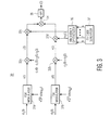
- FIG. 3 An exemplary non-coherent hybrid FH/DS system is shown in FIG. 3 , and is generally designated as 30.
- data modulation is binary FSK and two independent data streams are used to modulate two carriers that jointly hop.
- the method may be expanded to multilevel FSK to achieve greater throughput; and to multiple independent data streams that modulate multiple carriers which hop simultaneously for further increase in information capacity.
- an inversely multiplexed high rate data sequence may be used to modulate the hopping carriers.
- f 01 and f 02 are fixed FSK center frequencies
- d 1 (t) and d 2 ( t ) are data signals taking on values ⁇ 1
- T is the data bit duration.
- both data signals have the same rate, but that is not required for the operation of the method and, in general, the rates may be different and do not have to be commensurable.
- the signals u(t) and v(t) shown in Equations (10) and (11) are each further spread by the transmitter hopping sequence of Equation (4), then combined into a composite signal.
- the sum-frequency components of the composite signal is passed to the antenna via a high pass filter (HPF).
- HPF high pass filter
- non-coherent hybrid system 30 includes FSK modulators 31 a and 31 b for modulating carrier signals with the data signals. As shown, the FSK modulators provide output signals x(t) and y(t).
- Mixers 32a and 32b multiply x(t) and y(t), respectively, with combinations of PRN codes, namely, c 1 t - c 1 t ⁇ c 2 t ⁇ c 3 t , and c 2 t + c 3 t to produce u(t) and v(t), as shown. It will be understood that the combinations of PRN codes are produced by a signal combiner, which may be similar to signal combiner 14 shown in FIG. 1 .
- mixers 32c and 32d multiply signals u(t) and v(t), respectively, with the transmitter hopping signal h T (t). Similar to system 10, the transmitter hopping signal is produced by FH code generator 37 and frequency synthesizer 36. Finally, summer 34 and HPF 35 combine and filter, respectively, the signals to output s(t) (Equation 12). Output signal s(t) may be transmitted by way of an antenna (not shown).
- Signal s(t) which is generated by non-coherent hybrid system 30, may be demodulated by any conventional receiver. Coherent detection is, of course, not necessary.
- the signal generated by hybrid system 30, as well as its spectrum are shown in FIGS. 4A and 4B , respectively.
- the number of hopping frequencies is 1000; hopping range is from 40 to 70 MHz; fixed offset frequencies f 01 and f 02 are 5 MHz apart; data modulation is BFSK; hopping direct sequence spreading and data are not synchronized.
- the signal s(t) has a constant envelope.
- the present invention is applicable to all frequency hopped spread spectrum systems in which higher throughput is desired, but the switch to multilevel modulation schemes (e.g. MFSK) is not a good option due to channel characteristics.
- MFSK multilevel modulation schemes
- the scheme is multi carrier, the constant envelope property of single carrier frequency hopped systems is preserved, which means that the present invention produces power-efficient systems.
- the invention is, therefore, especially applicable to mobile and portable systems where preservation of battery power is of special importance.
- the output signal generated by the present invention is essentially single sideband, making the scheme bandwidth efficient. This makes the present invention applicable to situations where the available spectrum has to be shared by many different wireless systems.
Abstract
Description
- The present invention relates, in general, to spread spectrum communications. More specifically, the present invention relates to hybrid spread spectrum systems, which use both direct sequence and frequency hopping operations.
- Spread spectrum systems operate by spreading the spectrum of the communications signal well beyond the bandwidth of the unspread signal. Motivation for using spread spectrum signals is based on the following facts: (1) These systems have the ability to reject unintentional jamming by interfering signals so that information may be communicated. (2) Spread spectrum signals minimize interference with competing users since the power transmitted is spread over a large frequency bandwidth. (3) Since these signals cannot be readily demodulated without knowing the code and its precise timing, message privacy is attained. (4) The wide bandwidth of spread spectrum signals provides tolerance to multi-path propagation. (5) Multiple access or the ability to send many independent signals over the same frequency band is possible using spread spectrum techniques. Systems employing spread spectrum methods to communicate in a secure and non-interfering manner are well-known in the art.
- Spread spectrum systems may spread the communications signal using direct sequence or frequency hopping methods. In a direct sequence spread spectrum system, data bits are modulated with a spreading sequence before transmission. Each bit of information is modulated with a series of chips from the spreading sequence. The number of chips per bit defines the processing gain. A greater number of chips per bit creates a greater immunity to noise and other interference.
- The band spread is accomplished by means of a code that is independent of the data, and a synchronized reception with a code at the receiver is used for despreading the incoming signal. In operation, a data signal is multiplied by a pseudo-random noise (PN) sequence having a faster data rate than the data signal to be transmitted.
- Prior to application of the spreading code to the information bit stream, the information bits may undergo a series of digital operations which further increase the performance of the system. For example, the information bits may undergo differential encoding in order to be more tolerant to an incorrect phase lock in the receiver's phase locked loop (PLL). The information bits may be scrambled using a long scrambling sequence in order to further decrease the vulnerability of the system to interception.
- Direct sequence spread spectrum coding may use binary phase shift keying (BPSK). In a phase shift keyed system, information is carried in the phase of the signal. Two different phases are used to denote two different digital values. Whenever the sequence transitions from a "1" to a "0" or from a "0" to a "1 ", the phase of the signal transitions. Such a system is referred to as a BPSK system.
- Another form of spread spectrum is called frequency-hopped spread spectrum, where the carrier frequency signal is moved (hopped) around in the band in a pseudo-random fashion. The result is an increase in effective bandwidth over time. Specifically, in a frequency hopped spread spectrum system the carrier frequency is shifted in discrete increments in a pattern generated by a code sequence. In such a system, the signal frequency remains constant for a specified time duration, referred to as a hopping time. The system may be either a fast hop system or a slow hop system. In a fast hop system, the frequency hopping occurs at the rate that is greater than the message bit rate. In a slow hop system, the hop rate is less than the message bit rate. There is also an intermediate situation in which the hop rate and message bit rate are of the same order of magnitude.
- Hybrid spread spectrum systems, which use both direct sequence and frequency hopping to spread the original spectrum, come in different forms and their operation is extensively described in the literature. Spread spectrum systems that use multiple carriers are also known in the literature. What does not appear in any of the literature, however, is that the output signal of hybrid multi-carrier spread spectrum systems may have a constant envelope.
- Since a conventional hybrid spread spectrum system does not transmit a signal having a constant envelope, it has shortcomings. A main shortcoming is low power efficiency, since a high power amplifier cannot operate efficiently when the input signal does not have a constant envelope. Another downside of such a system is its low bandwidth efficiency, since the common way to increase throughput is to increase bandwidth.
- The present invention addresses systems and methods for generating hybrid spread spectrum signals, using both direct sequence and frequency hopping, having constant envelopes.
- To meet this and other needs, and in view of its purposes, the present invention provides a hybrid spread spectrum system. The system includes a signal combiner for (a) receiving a plurality of spread spectrum encoded data signals and (b) forming a plurality of combined signals. A first set of mixers is included for (a) receiving the plurality of combined signals and at least two carriers, and (b) forming at least a two-carrier, constant envelope signal. A second set of mixers is also included for (a) receiving the at least two-carrier, constant envelope signal and a transmitter hopping signal and (b) forming a hybrid spread spectrum signal. The combined signals include (a) [s1(t) - s1(t)s2(t)s3(t)] and (b) [s2(t) + s3(t)], where s¡(t) are three separate spread spectrum encoded data signals. The transmitter hopping signal is a sequence of tones having (a) a duration Tc, where Tc is a chip duration, and (b) frequencies fn taken from a set of 2k values, where k is a number of bits from a pseudo-random noise (PRN) sequence.
- The two carrier, constant envelope signal includes a first carrier modulated by [s1(t) - s1(t)s2(t)s3(t)] and a second carrier modulated by [s2(t) + s3(t)]. The s¡(t) are three separate spread spectrum encoded data signals. The first set of mixers receives at least three carriers and forms at least a three-carrier constant envelope signal, and the second set of mixers receives the at least three-carrier constant envelope signal and forms the hybrid spread spectrum signal. The second set of mixers includes a summer for combining signals outputted by the second set of mixers, and a high pass filter (HPF) for (a) receiving a signal from the summer and (b) producing a single sideband of the hybrid spread spectrum signal.
- Another embodiment of the invention is a hybrid spread spectrum system having a plurality of frequency shift keying (FSK) modulators for forming at least two FSK modulated carriers. A first set of mixers is included for (a) receiving the at least two FSK modulated carriers and a plurality of PRN codes, and (b) forming at least two direct spread carriers. A second set of mixers is also included for (a) receiving the at least two direct spread carriers and a transmitter hopping signal, and (b) forming a hybrid spread spectrum signal having a constant envelope. The plurality of PRN codes includes (a) [c1(t) - c1(t)c2(t)c3(t)] and (b) [c2(t) + c3(t)], where ci(t) are three separate PRN codes. The transmitter hopping signal is a sequence of tones having (a) duration Tc, where Tc is a chip duration, and (b) frequencies fn taken from a set of 2k values, where k is a number of bits from a PRN sequence. The at least two direct spread carriers include a first carrier modulated by [c1(t) - c1(t)c2(t)c3(t)] and a second carrier modulated by [c2(t) + c3(t)], where c¡(t) are three separate PRN codes. The second set of mixers includes a summer for combining signals outputted by the second set of mixers, and a HPF for (a) receiving a signal from the summer and (b) producing a single sideband of the hybrid spread spectrum signal.
- Yet another embodiment of the present invention is a method for transmitting a hybrid spread spectrum signal. The method includes the steps of: (a) forming at least two FSK modulated carriers; (b) (i) receiving the at least two FSK modulated carriers and a plurality of PRN codes, and (ii) forming at least two direct spread spectrum carriers, and (c) (i) receiving the at least two direct spread carriers and a transmitter hopping signal, and (ii) forming a hybrid spread spectrum signal having a constant envelope. The plurality of PRN codes includes (i) [c1(t) - c1(t)c2(t)c3(t)] and (ii) [c2(t) + c3(t)], where c¡(t) are three separate PRN codes. The transmitter hopping signal is a sequence of tones having (i) duration Tc, where Tc is a chip duration, and (ii) frequencies fn taken from a set of 2k values, where k is a number of bits from a PRN sequence. The at least two direct spread carriers include a first carrier modulated by [c1(t) - c1(t)c2(t)c3(t)] and a second carrier modulated by [c2(t) + c3(t)], where c¡(t) are three separate PRN codes.
- The method further includes the steps of: (d) high pass filtering the hybrid spread spectrum signal having the constant envelope, and (e) transmitting the high pass filtered hybrid spread spectrum signal of step (d).
- It is understood that the foregoing general description and the following detailed description are exemplary, but are not restrictive, of the invention.
- The invention is best understood from the following detailed description when read in connection with the accompanying figures.
-
FIG. 1 is a block diagram of a coherent hybrid frequency hopping/direct sequence (FH/DS) system for generating an FH/DS signal, in accordance with an embodiment of the present invention. -
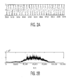
FIG. 2A is a plot of amplitude versus time for the output signal generated by the system ofFIG. 1 . -
FIG. 2B is a spectral plot of power versus frequency of the output signal generated by the system shown inFIG. 1 . -
FIG. 3 is a block diagram of a coherent hybrid frequency hopping/direct sequence (FH/DS) system for generating an FH/DS signal, in accordance with another embodiment of the present invention. -
FIG. 4A is a plot of amplitude versus time for the output signal generated by the system ofFIG. 3 . -
FIG. 4B is a spectral plot of power versus frequency of the output signal generated by the system shown inFIG. 3 . - The present invention is a hybrid spread spectrum system, which uses both direct sequence and frequency hopping techniques. The present invention has multipath and jamming resistant properties of similar conventional systems, but overcomes their shortcomings through use of a novel method for combining the spreading codes, and the use of multiple carriers that hop simultaneously. The arrangement of codes that spread the hopping carriers is such that it produces a composite output signal with a constant envelope. This makes the present invention power efficient, since high power amplifiers may be operated in their optimal mode, that is, close to the 1dB (saturation) point.
- In addition, since multiple carriers hop simultaneously, the throughput of the system is increased in comparison with single carrier hopping systems. Every one of the carriers may be separately modulated by an independent data stream, or a high rate data stream may be inversely multiplexed onto several carriers. Furthermore, multiple carriers may be used to combat multipath or jamming, since redundancy in transmission may be achieved by having the same information repeated on two or more carriers. Finally, the single sideband property of the system included in the present invention achieves high bandwidth efficiency.
- As will be explained, the present invention includes coherent and non-coherent systems. Both systems use a combination of direct sequence and frequency hopping for carrier spreading, but they differ in the way in which the data modulates the carriers. In a BPSK (or DPSK) system, data demodulation has to be coherent, but in an FSK system, data may be demodulated non-coherently, which is a big advantage in wireless systems.
- Referring to
FIG. 1 , there is shown a coherent hybrid frequency hopping/direct sequence (FH/DS) system for generating an FH/DS signal, the hybrid system generally designated as 10. As shown, two carriers are hopping simultaneously. The carriers are modulated with three data streams, which may either originate from independent sources or be a result of inverse multiplexing of a single high data rate source. - It will be appreciated that the signal generated by the hybrid system of
FIG. 1 is exemplary and is provided to illustrate the concept. The system may be easily extended to include more than two carriers and more than three data streams. - The present inventor in
U.S. Application No. 11/067,148, filed on February 25, 2005 , describes generation of a two carrier, constant envelope signal. Description of the system and method of generating this two carrier constant envelope signal is incorporated herein by reference in its entirety. - As described in the aforementioned U.S. Application, consider a two-carrier, constant envelope signal, such as:


- Signals d'i (t) are obtained by differentially encoding data sequences di (t). Differential encoding, however, is not necessary for the present invention. Signals ci (t) are pseudo-random (PRN) sequences with rates much higher than rates of di (t) , so they act like spreading codes. Both data and PRN signals take on values of ±1.
- To produce the output RF signal, z(t) is used to modulate the transmitter hopping signal, which is a sequence of tones of duration Tc as follows:

- Frequency fn is taken from a set of 2 k values, where k is the number of bits from the PRN sequence that is taken at the time to determine the current hopping frequency value. Pulse p(t) has unit amplitude in 0 ≤ t ≤ Tc , where Tc is the chip duration.
- Therefore, the output signal is

- Referring again to
FIG. 1 ,coherent hybrid system 10 includesdifferential encoders Mixers -
Signal combiner 14, which also includes multiplier functions, receives the s¡(t) signals and produces the following two combined signals:

- Each combined signal is then multiplied, using
respective mixers - Next, the two modulated carriers are multiplied, using
respective mixers hopping code generator 19 andfrequency synthesizer 18 produce the hopping signal.Summer 16 and high pass filter (HPF) 17, which are inserted serially insystem 10, produce the final output signal s(t) (Equation 5). It will be appreciated that output signal s(t) may be transmitted via an antenna (not shown). - The sum-frequency is passed through a transmit high pass filter (HPF). The signal in Equation (5) is a hybrid, direct sequence/frequency hopping spread spectrum (DS/FH-SS) signal. Namely, two direct sequence spread carriers at frequencies f 01 + fn and f 02 + fn hop simultaneously.
- In addition, signal s(t) has a constant envelope, because


- The signal, which is generated using the system shown in
FIG. 1 , and its spectrum are shown inFIGS. 2A and 2B , respectively. In this example, the number of hopping frequencies is 100; the hopping range is from 40 to 70 MHz; the fixed offset frequencies f 01 and f 02, are 5 MHz apart; the data and direct sequence spreading modulations are BPSK. The hopping and direct spreading sequences need not be synchronized. The signal has a constant envelope. - When the signal generated by the system of
FIG. 1 , namely s(t), is transmitted and received by a receiver (not shown), it may be demodulated by any conventional spread spectrum receiver, including a despreader and a demodulator. The demodulator, of course, should be a coherent demodulator. - A disadvantage in using the signal s(t) shown in
FIG. 1 is that it requires coherent demodulation, which is difficult to accomplish in frequency hopping systems. Therefore, the present invention also provides a system and method for generating signals that may be demodulated non-coherently, but are also of a hybrid FH/DS type and have a constant envelope. - An exemplary non-coherent hybrid FH/DS system is shown in
FIG. 3 , and is generally designated as 30. In the example ofsystem 30, data modulation is binary FSK and two independent data streams are used to modulate two carriers that jointly hop. The method, however, may be expanded to multilevel FSK to achieve greater throughput; and to multiple independent data streams that modulate multiple carriers which hop simultaneously for further increase in information capacity. In addition, instead of independent data streams, an inversely multiplexed high rate data sequence may be used to modulate the hopping carriers. - For example, consider the following BFSK modulated carriers:


f 01 and f 02 are fixed FSK center frequencies;
d 1 (t) and d 2(t) are data signals taking on values ±1;

T is the data bit duration. - For simplicity, it is assumed that both data signals have the same rate, but that is not required for the operation of the method and, in general, the rates may be different and do not have to be commensurable.
- By using combinations of PRN codes c 1(t), c 2(t), and c 3(t), the present invention direct-spreads the carriers from Equations (8) and (9) to


- The signals u(t) and v(t) shown in Equations (10) and (11) are each further spread by the transmitter hopping sequence of Equation (4), then combined into a composite signal. The sum-frequency components of the composite signal is passed to the antenna via a high pass filter (HPF). The entire output signal is given by

- Referring still to
FIG. 3 ,non-coherent hybrid system 30 includesFSK modulators -
Mixers 

combiner 14 shown inFIG. 1 . - Next,
mixers system 10, the transmitter hopping signal is produced byFH code generator 37 andfrequency synthesizer 36. Finally,summer 34 andHPF 35 combine and filter, respectively, the signals to output s(t) (Equation 12). Output signal s(t) may be transmitted by way of an antenna (not shown). - Signal s(t), which is generated by
non-coherent hybrid system 30, may be demodulated by any conventional receiver. Coherent detection is, of course, not necessary. - The signal generated by
hybrid system 30, as well as its spectrum are shown inFIGS. 4A and 4B , respectively. In this example, the number of hopping frequencies is 1000; hopping range is from 40 to 70 MHz; fixed offset frequencies f 01 and f 02 are 5 MHz apart; data modulation is BFSK; hopping direct sequence spreading and data are not synchronized. As shown inFIG. 4A , the signal s(t) has a constant envelope. - The present invention is applicable to all frequency hopped spread spectrum systems in which higher throughput is desired, but the switch to multilevel modulation schemes (e.g. MFSK) is not a good option due to channel characteristics. Although the scheme is multi carrier, the constant envelope property of single carrier frequency hopped systems is preserved, which means that the present invention produces power-efficient systems. The invention is, therefore, especially applicable to mobile and portable systems where preservation of battery power is of special importance. Furthermore, the output signal generated by the present invention is essentially single sideband, making the scheme bandwidth efficient. This makes the present invention applicable to situations where the available spectrum has to be shared by many different wireless systems.
Claims (18)
- A hybrid spread spectrum system (10) comprisinga signal combiner (14) for (a) receiving a plurality of spread spectrum encoded data signals (si(t)) and (b) forming a plurality of combined signals,a first set of mixers (15a, 15b) for (a) receiving the plurality of combined signals and at least two carriers, and (b) forming at least a two-carrier, constant envelope signal, anda second set of mixers (15c, 15d) for (a) receiving the at least two-carrier, constant envelope signal and a transmitter hopping signal and (b) forming a hybrid spread spectrum signal.
- The hybrid spread spectrum system of claim 1, wherein
the combined signals include (a) [s1(t) - s1(t)s2(t)s3(t)] and (b) [s2(t) + s3(t)], where s¡(t) are three separate spread spectrum encoded data signals. - The hybrid spread spectrum system of one of claims 1 or 2, wherein
the two carrier, constant envelope signal includes a first carrier modulated by [s1(t) - s1(t)s2(t)s3(t)] and a second carrier modulated by [s2(t) + s3(t)],
where s¡(t) are three separate spread spectrum encoded data signals. - The hybrid spread spectrum system of claim 1, wherein
the first set of mixers receives three carriers and forms a three-carrier constant envelope signal, and
the second set of mixers receives the three-carrier constant envelope signal and forms the hybrid spread spectrum signal. - The hybrid spread spectrum system of one of claims 1 to 4, wherein
the plurality of spread spectrum encoded data signals include differentially encoded data sequences modulated by PRN sequences with rates higher than rates of the encoded data sequences. - The hybrid spread spectrum system of claim 3, wherein


- A hybrid spread spectrum system comprisinga plurality of frequency shift keying (FSK) modulators (31 a, 31 b) for forming at least two FSK modulated carriers (x(t), y(t)),a first set of mixers (32a, 32b) for (a) receiving the at least two FSK modulated carriers and a plurality of PRN codes, and (b) forming at least two direct spread carriers, anda second set of mixers (32c, 32d) for (a) receiving the at least two direct spread carriers and a transmitter hopping signal, and (b) forming a hybrid spread spectrum signal having a constant envelope.
- A hybrid spread spectrum system of claim 7, wherein
the plurality of PRN codes includes
where c¡(t) are three separate PRN codes. - A hybrid spread spectrum system (10, 30) of one of claims 1 to 8, wherein the transmitter hopping signal is a sequence of tones having (a) duration Tc, where Tc is a chip duration, and (b) frequencies fn taken from a set of 2k values, where k is a number of bits from a pseudo random noise (PRN) sequence.
- A hybrid spread spectrum system (30) of claim 7, wherein
the at least two direct spread carriers include a first carrier modulated by [c1(t) - c1(t)c2(t)c3(t)] and a second carrier modulated by [c2(t) + c3(t)],
where ci(t) are three separate PRN codes. - A hybrid spread spectrum system (10, 30) of one of claims 1 to 10, wherein
the second set of mixers (15c,15d; 32c, 32d) includes a summer (16; 34) for combining signals outputted by the second set of mixers (15c,15d; 32c, 32d), and
a HPF (17, 35) for (a) receiving a signal from the summer and (b) producing a single sideband of the hybrid spread spectrum signal. - A hybrid spread spectrum system of claim 7, wherein


- A method for transmitting a hybrid spread spectrum signal comprising the steps of:(a) forming at least two FSK modulated carriers;(b) (i) receiving the at least two FSK modulated carriers and a plurality of PRN codes, and (ii) forming at least two direct spread spectrum carriers, and(c) (i) receiving the at least two direct spread carriers and a transmitter hopping signal, and (ii) forming a hybrid spread spectrum signal having a constant envelope.
- The method of claim 13, wherein
the plurality of PRN codes includes
where cl(t) are three separate PRN codes. - The method of claim 13, wherein
the transmitter hopping signal is a sequence of tones having (i) duration Tc, where Tc is a chip duration, and (ii) frequencies fn taken from a set of 2k values, where k is a number of bits from a PRN sequence. - The method of claim 13, wherein
the at least two direct spread carriers include a first carrier modulated by [c1(t) - c1(t)c2(t)c3(t)] and a second carrier modulated by [c2(t) + c3(t)],
where c¡(t) are three separate PRN codes. - The method of claim 13, further comprising the steps of:(d) high pass filtering the hybrid spread spectrum signal having the constant envelope, and(e) transmitting the high pass filtered hybrid spread spectrum signal of step (d).
- The method of claim 13, wherein


Applications Claiming Priority (1)
| Application Number | Priority Date | Filing Date | Title |
|---|---|---|---|
| US11/880,564 US7894504B2 (en) | 2007-07-23 | 2007-07-23 | Coherent and non-coherent hybrid direct sequence/frequency hopping spread spectrum systems with high power and bandwidth efficiency and methods thereof |
Publications (3)
| Publication Number | Publication Date |
|---|---|
| EP2019495A2 true EP2019495A2 (en) | 2009-01-28 |
| EP2019495A3 EP2019495A3 (en) | 2012-05-02 |
| EP2019495B1 EP2019495B1 (en) | 2013-10-09 |
Family
ID=39858242
Family Applications (1)
| Application Number | Title | Priority Date | Filing Date |
|---|---|---|---|
| EP08160835.8A Active EP2019495B1 (en) | 2007-07-23 | 2008-07-21 | Coherent and non-coherent direct sequence/frequency hopping spread spectrum systems with high power and bandwidth efficiency and method thereof. |
Country Status (3)
| Country | Link |
|---|---|
| US (1) | US7894504B2 (en) |
| EP (1) | EP2019495B1 (en) |
| ES (1) | ES2441546T3 (en) |
Cited By (1)
| Publication number | Priority date | Publication date | Assignee | Title |
|---|---|---|---|---|
| CN103701490A (en) * | 2014-01-15 | 2014-04-02 | 西安电子科技大学 | Hybrid spread spectrum communication system based on low density parity code (LDPC) encoding and method thereof |
Families Citing this family (6)
| Publication number | Priority date | Publication date | Assignee | Title |
|---|---|---|---|---|
| US8761230B2 (en) * | 2009-06-08 | 2014-06-24 | Adeptence, Llc | Method and apparatus for continuous phase modulation preamble encoding and decoding |
| US8369451B2 (en) * | 2009-06-09 | 2013-02-05 | Adeptence, Llc | Method and apparatus for constant envelope modulation |
| US8401118B2 (en) * | 2009-06-09 | 2013-03-19 | Adeptence Llc | Method and apparatus for constant envelope demodulation |
| CN107104780B (en) * | 2009-10-01 | 2020-10-16 | 交互数字专利控股公司 | Uplink control data transmission |
| CN102812658B (en) | 2010-01-08 | 2015-12-16 | 交互数字专利控股公司 | For the method and apparatus of the channel state information transmission of multiple carrier wave |
| DE102017206236A1 (en) * | 2017-04-11 | 2018-10-11 | Fraunhofer-Gesellschaft zur Förderung der angewandten Forschung e.V. | SPECIFIC HOPPING PATTERN FOR TELEGRAM SPLITTING |
Citations (1)
| Publication number | Priority date | Publication date | Assignee | Title |
|---|---|---|---|---|
| US20060188267A1 (en) | 2005-02-23 | 2006-08-24 | Pavle Gavrilovic | System and method for suppression of stimulated Brillouin scattering in optical transmission communications |
Family Cites Families (6)
| Publication number | Priority date | Publication date | Assignee | Title |
|---|---|---|---|---|
| JP2914446B1 (en) * | 1998-02-09 | 1999-06-28 | 日本電気株式会社 | Channel allocation method, transmission / reception device, and communication system |
| US6278722B1 (en) * | 1998-02-25 | 2001-08-21 | Lucent Technologies Inc. | Architecture for a digital portable telephone |
| US6128330A (en) * | 1998-11-24 | 2000-10-03 | Linex Technology, Inc. | Efficient shadow reduction antenna system for spread spectrum |
| US6289038B1 (en) * | 1999-01-15 | 2001-09-11 | Samsung Electronics Co., Inc. | Parallel hopping hybrid direct sequence/slow frequency hopping CDMA system |
| AU2001293120A1 (en) * | 2000-09-27 | 2002-04-08 | Itt Manufacturing Enterprises, Inc. | Intervote modulator |
| US7656931B2 (en) * | 2003-12-31 | 2010-02-02 | Ut-Battelle, Llc | Hybrid spread spectrum radio system |
-
2007
- 2007-07-23 US US11/880,564 patent/US7894504B2/en active Active
-
2008
- 2008-07-21 ES ES08160835.8T patent/ES2441546T3/en active Active
- 2008-07-21 EP EP08160835.8A patent/EP2019495B1/en active Active
Patent Citations (1)
| Publication number | Priority date | Publication date | Assignee | Title |
|---|---|---|---|---|
| US20060188267A1 (en) | 2005-02-23 | 2006-08-24 | Pavle Gavrilovic | System and method for suppression of stimulated Brillouin scattering in optical transmission communications |
Cited By (2)
| Publication number | Priority date | Publication date | Assignee | Title |
|---|---|---|---|---|
| CN103701490A (en) * | 2014-01-15 | 2014-04-02 | 西安电子科技大学 | Hybrid spread spectrum communication system based on low density parity code (LDPC) encoding and method thereof |
| CN103701490B (en) * | 2014-01-15 | 2016-05-25 | 西安电子科技大学 | Based on mixed spread spectrum communication system and the method thereof of LDPC coding |
Also Published As
| Publication number | Publication date |
|---|---|
| EP2019495A3 (en) | 2012-05-02 |
| US20090028219A1 (en) | 2009-01-29 |
| EP2019495B1 (en) | 2013-10-09 |
| ES2441546T3 (en) | 2014-02-05 |
| US7894504B2 (en) | 2011-02-22 |
Similar Documents
| Publication | Publication Date | Title |
|---|---|---|
| US5515396A (en) | Method and apparatus for selecting a spreading code in a spectrum spread communication system | |
| EP2019495B1 (en) | Coherent and non-coherent direct sequence/frequency hopping spread spectrum systems with high power and bandwidth efficiency and method thereof. | |
| US7515627B2 (en) | System and method for ultra-wideband (UWB) communication transceiver | |
| US20080279287A1 (en) | Code Type Transmitting Device and Code Type Receiving Device | |
| EP1352489B1 (en) | Hybrid spread-spectrum technique for expanding channel capacity | |
| EP2993845B1 (en) | Improvement of spread spectrum GMSK signals | |
| CN110198177B (en) | Multi-sequence combined frequency hopping communication method combined with pseudo-random feature codes | |
| JP2004015828A (en) | Method for modulating data bit, and system for modulating and demodulating digital data | |
| US10348360B2 (en) | Signal representing data, method and device for generating such signal and method and device for determining the represented data from such signal | |
| US6781980B1 (en) | CDMA transmitter and method generating combined high-rate and low-rate CDMA signals | |
| AU2001294864A1 (en) | Hybrid spread-spectrum technique for expanding channel capacity | |
| US6674790B1 (en) | System and method employing concatenated spreading sequences to provide data modulated spread signals having increased data rates with extended multi-path delay spread | |
| JPH08509590A (en) | Method and apparatus for time division multiplexing the use of spreading codes in a communication system | |
| US6363100B1 (en) | Radio data communication system using spread spectrum scheme | |
| JP2005304029A (en) | Frequency staggered frequency deviation modulation | |
| CN101040455B (en) | Method and modulator for modulating sequence of bits in wireless communications network | |
| EP1077532A1 (en) | Spread Spectrum Signal Generator and Decoder for Single Sideband Transmission | |
| EP0999668A2 (en) | A method and apparatus for achieving channel variability in spread spectrum communication systems | |
| Matolak et al. | Performance of multitone and multicarrier direct sequence spread spectrum in the presence of partial-band pulse jamming/interference | |
| JPH066324A (en) | Spread spectrum communication method | |
| JPH07111495A (en) | Method for spread spectrum communication and its transmitter and receiver | |
| JP2875662B2 (en) | Spread spectrum modulator and demodulator | |
| Hunt et al. | Evaluation and Comparison of a New Robust Waveform Against Direct Sequence Spread Spectrum for HF | |
| JP2001168771A (en) | Communication equipment and spread spectrum communication method | |
| Panchal et al. | Ber analysis for a FFH spread spectrum system employing DPSK modulation over a Rayleigh fading channel |
Legal Events
| Date | Code | Title | Description |
|---|---|---|---|
| PUAI | Public reference made under article 153(3) epc to a published international application that has entered the european phase |
Free format text: ORIGINAL CODE: 0009012 |
|
| 17P | Request for examination filed |
Effective date: 20080721 |
|
| AK | Designated contracting states |
Kind code of ref document: A2 Designated state(s): AT BE BG CH CY CZ DE DK EE ES FI FR GB GR HR HU IE IS IT LI LT LU LV MC MT NL NO PL PT RO SE SI SK TR |
|
| AX | Request for extension of the european patent |
Extension state: AL BA MK RS |
|
| PUAL | Search report despatched |
Free format text: ORIGINAL CODE: 0009013 |
|
| AK | Designated contracting states |
Kind code of ref document: A3 Designated state(s): AT BE BG CH CY CZ DE DK EE ES FI FR GB GR HR HU IE IS IT LI LT LU LV MC MT NL NO PL PT RO SE SI SK TR |
|
| AX | Request for extension of the european patent |
Extension state: AL BA MK RS |
|
| RIC1 | Information provided on ipc code assigned before grant |
Ipc: H04B 1/713 20110101ALN20120323BHEP Ipc: H04B 1/69 20110101AFI20120323BHEP |
|
| 17Q | First examination report despatched |
Effective date: 20120423 |
|
| RAP1 | Party data changed (applicant data changed or rights of an application transferred) |
Owner name: EXELIS INC. |
|
| AKX | Designation fees paid |
Designated state(s): DE ES GB IT |
|
| RIC1 | Information provided on ipc code assigned before grant |
Ipc: H04B 1/713 20110101ALN20130219BHEP Ipc: H04B 1/692 20110101ALI20130219BHEP Ipc: H04B 1/69 20110101AFI20130219BHEP |
|
| GRAP | Despatch of communication of intention to grant a patent |
Free format text: ORIGINAL CODE: EPIDOSNIGR1 |
|
| RIC1 | Information provided on ipc code assigned before grant |
Ipc: H04B 1/713 20110101ALN20130408BHEP Ipc: H04B 1/69 20110101AFI20130408BHEP Ipc: H04B 1/692 20110101ALI20130408BHEP |
|
| INTG | Intention to grant announced |
Effective date: 20130506 |
|
| GRAS | Grant fee paid |
Free format text: ORIGINAL CODE: EPIDOSNIGR3 |
|
| GRAA | (expected) grant |
Free format text: ORIGINAL CODE: 0009210 |
|
| AK | Designated contracting states |
Kind code of ref document: B1 Designated state(s): DE ES GB IT |
|
| REG | Reference to a national code |
Ref country code: GB Ref legal event code: FG4D |
|
| REG | Reference to a national code |
Ref country code: DE Ref legal event code: R096 Ref document number: 602008027979 Country of ref document: DE Effective date: 20131205 |
|
| REG | Reference to a national code |
Ref country code: ES Ref legal event code: FG2A Ref document number: 2441546 Country of ref document: ES Kind code of ref document: T3 Effective date: 20140205 |
|
| REG | Reference to a national code |
Ref country code: DE Ref legal event code: R097 Ref document number: 602008027979 Country of ref document: DE |
|
| REG | Reference to a national code |
Ref country code: DE Ref legal event code: R082 Ref document number: 602008027979 Country of ref document: DE Representative=s name: PATENTANWAELTE MAGENBAUER & KOLLEGEN, DE Ref country code: DE Ref legal event code: R082 Ref document number: 602008027979 Country of ref document: DE Representative=s name: PATENTANWAELTE MAGENBAUER & KOLLEGEN PARTNERSC, DE |
|
| PLBE | No opposition filed within time limit |
Free format text: ORIGINAL CODE: 0009261 |
|
| STAA | Information on the status of an ep patent application or granted ep patent |
Free format text: STATUS: NO OPPOSITION FILED WITHIN TIME LIMIT |
|
| 26N | No opposition filed |
Effective date: 20140710 |
|
| REG | Reference to a national code |
Ref country code: DE Ref legal event code: R097 Ref document number: 602008027979 Country of ref document: DE Effective date: 20140710 |
|
| REG | Reference to a national code |
Ref country code: DE Ref legal event code: R082 Ref document number: 602008027979 Country of ref document: DE Representative=s name: PATENTANWAELTE MAGENBAUER & KOLLEGEN PARTNERSC, DE Ref country code: DE Ref legal event code: R081 Ref document number: 602008027979 Country of ref document: DE Owner name: HARRIS GLOBAL COMMUNICATIONS, INC., ALBANY, US Free format text: FORMER OWNER: EXELIS INC., MCLEAN, VA., US |
|
| REG | Reference to a national code |
Ref country code: GB Ref legal event code: 732E Free format text: REGISTERED BETWEEN 20190207 AND 20190213 |
|
| REG | Reference to a national code |
Ref country code: ES Ref legal event code: PC2A Owner name: HARRIS GLOBAL COMMUBICATIONS, INC. Effective date: 20190808 |
|
| PGFP | Annual fee paid to national office [announced via postgrant information from national office to epo] |
Ref country code: IT Payment date: 20220721 Year of fee payment: 15 Ref country code: ES Payment date: 20220801 Year of fee payment: 15 |
|
| P01 | Opt-out of the competence of the unified patent court (upc) registered |
Effective date: 20230612 |
|
| PGFP | Annual fee paid to national office [announced via postgrant information from national office to epo] |
Ref country code: GB Payment date: 20230727 Year of fee payment: 16 |
|
| PGFP | Annual fee paid to national office [announced via postgrant information from national office to epo] |
Ref country code: DE Payment date: 20230727 Year of fee payment: 16 |