EP2017145B1 - Method and sensor for detecting occurrences of wetting on a pane - Google Patents
Method and sensor for detecting occurrences of wetting on a pane Download PDFInfo
- Publication number
- EP2017145B1 EP2017145B1 EP08007649A EP08007649A EP2017145B1 EP 2017145 B1 EP2017145 B1 EP 2017145B1 EP 08007649 A EP08007649 A EP 08007649A EP 08007649 A EP08007649 A EP 08007649A EP 2017145 B1 EP2017145 B1 EP 2017145B1
- Authority
- EP
- European Patent Office
- Prior art keywords
- light
- measuring
- optical measuring
- current
- pane
- Prior art date
- Legal status (The legal status is an assumption and is not a legal conclusion. Google has not performed a legal analysis and makes no representation as to the accuracy of the status listed.)
- Not-in-force
Links
Images
Classifications
-
- B—PERFORMING OPERATIONS; TRANSPORTING
- B60—VEHICLES IN GENERAL
- B60S—SERVICING, CLEANING, REPAIRING, SUPPORTING, LIFTING, OR MANOEUVRING OF VEHICLES, NOT OTHERWISE PROVIDED FOR
- B60S1/00—Cleaning of vehicles
- B60S1/02—Cleaning windscreens, windows or optical devices
- B60S1/04—Wipers or the like, e.g. scrapers
- B60S1/06—Wipers or the like, e.g. scrapers characterised by the drive
- B60S1/08—Wipers or the like, e.g. scrapers characterised by the drive electrically driven
- B60S1/0818—Wipers or the like, e.g. scrapers characterised by the drive electrically driven including control systems responsive to external conditions, e.g. by detection of moisture, dirt or the like
-
- G—PHYSICS
- G01—MEASURING; TESTING
- G01N—INVESTIGATING OR ANALYSING MATERIALS BY DETERMINING THEIR CHEMICAL OR PHYSICAL PROPERTIES
- G01N21/00—Investigating or analysing materials by the use of optical means, i.e. using sub-millimetre waves, infrared, visible or ultraviolet light
-
- G—PHYSICS
- G01—MEASURING; TESTING
- G01N—INVESTIGATING OR ANALYSING MATERIALS BY DETERMINING THEIR CHEMICAL OR PHYSICAL PROPERTIES
- G01N21/00—Investigating or analysing materials by the use of optical means, i.e. using sub-millimetre waves, infrared, visible or ultraviolet light
- G01N21/17—Systems in which incident light is modified in accordance with the properties of the material investigated
- G01N21/55—Specular reflectivity
- G01N21/552—Attenuated total reflection
-
- G—PHYSICS
- G01—MEASURING; TESTING
- G01N—INVESTIGATING OR ANALYSING MATERIALS BY DETERMINING THEIR CHEMICAL OR PHYSICAL PROPERTIES
- G01N21/00—Investigating or analysing materials by the use of optical means, i.e. using sub-millimetre waves, infrared, visible or ultraviolet light
- G01N21/17—Systems in which incident light is modified in accordance with the properties of the material investigated
- G01N21/41—Refractivity; Phase-affecting properties, e.g. optical path length
- G01N21/43—Refractivity; Phase-affecting properties, e.g. optical path length by measuring critical angle
- G01N2021/435—Sensing drops on the contact surface
Definitions
- the invention relates to a method and a sensor for detecting occurrences of wetting on a pane, particularly a rain sensor for vehicles.
- Rain sensors have optical measuring sections which contain a light transmitter and a light receiver. Light transmitters and light receivers are coupled to the inner side of the pane so that light emitted from the light transmitter is reflected onto the light receiver by total reflection on the outer surface of the pane. However, the light receiver is also exposed to the ambient light. In order to reduce the influence of the ambient light, two identical optical measuring sections can be used which are arranged adjacent to each other, with the differential signal of the light receivers then being evaluated. However, the modulation capability is limited by outside light and the asymmetry of the optical and electronic components.
- EP 1 641 013 A1 shows a rain sensor in which two emitters and two detectors are used to form four optical paths of equal length and optical efficiency.
- DE 197 23 859 A1 shows a rain sensor where the current flowing in a light receiver is integrated over a fixed integration time interval.
- the integration time intervals are fixed predetermined time values. Different integration time intervals are necessary to adapt the sensor to high and low amounts of external light.
- the present invention provides a method and a sensor for detecting occurrences of wetting on a pane, by which the usable modulation range and the detection sensitivity are increased.
- the method according to the invention operates with successive, continuously repeated measuring cycles.
- a current/voltage transformer which can be formed by a measuring capacitor, is charged by the current flowing in a light receiver of a first optical measuring section up to a first threshold value.
- the measuring capacitor is discharged by the current flowing in a light receiver of a second optical measuring section to a second threshold value.
- the light transmitters of the optical measuring sections are closed-loop regulated over several measuring cycles to predetermined rated values for the charging time and the discharging time.
- a conclusion is finally drawn with regard to the wetting of the pane from the instantaneous deviations between the rated values and actually measured values of charging times and discharging times.
- the available modulation range is adapted dynamically to the prevailing conditions by the systematic control of the intensity of the light transmitters in the two optical measuring sections.
- the upper limit of the modulation range is extended to higher values of the ambient light.
- the sensor according to the invention for detecting occurrences of wetting on a pane has two optical measuring sections which are able to be coupled to the pane, each of which has a controllable light transmitter and a light receiver.
- the sensor further comprises a comparator, the first input of which is connected with a measuring capacitor and at the second input of which one or other of two threshold values is applied selectively by means of a change-over switch.
- a control circuit controls the light transmitters alternately.
- the control circuit connects the measuring capacitor selectively with the light receivers via a controllable switch.
- the control circuit for example a programmed micro-controller or an application-specific integrated circuit (ASIC) carries out a sequence control such that in continuously repeated measuring cycles, respectively in a first cycle section the measuring capacitor is charged by the current flowing in the light receiver of the first optical measuring section up to the first threshold value, and in a subsequent second cycle section the measuring capacitor is discharged by the current flowing in the light receiver of the second optical measuring section to the second threshold value.
- the light transmitters of the two optical measuring sections are closed-loop regulated over several measuring cycles to predetermined rated values for the charging time and the discharging time.
- a wetting of the pane is detected based on instantaneous deviations between the rated values and actually measured values of charging times and discharging times, and a corresponding control signal is provided, for example a control signal for the windscreen wiper system of a vehicle.
- the sensor contains two optical measuring sections which are coupled to the inner surface of the pane.
- the first optical measuring section consists of a light transmitter LED1 in series with a controllable current source CUR1, and a light receiver P1.
- the second optical measuring section consists of a light transmitter LED2 in series with a controllable current source CUR2, and a light receiver P2.
- the association between light transmitters and light receivers is symbolized in Figure 1 respectively by an arrow.
- the light receivers P1, P2 are arranged in series with each other and with two resistances symmetrically between the two poles of a constant voltage source U.
- a measuring capacitor C1 is able to be connected by means of a controllable switch SW1 with the connection point between the light receivers P1, P2.
- the measuring capacitor C1 is additionally connected with the non-inverting input of a comparator COMP, the inverting input of which can be connected via a change-over switch SW4 with one or other of two fixed threshold values INTHIGH and INTLOW.
- the two fixed threshold values INTHIGH and INTLOW are derived by means of a resistive voltage divider from the constant voltage source U.
- the change-over switch SW4 is controlled by the output signal STATUS of the comparator COMP.
- the measuring capacitor C1 is used for the integration of the current flow in the light receivers.
- This measuring capacitor has the function of a current/voltage transformer.
- a current/voltage transformer is used with an additional filter and a separate integration circuit.
- a control circuit CONTROL controls the current source CUR1 of the first optical measuring section and the current source CUR2 of the second optical measuring section. To do this, the control circuit connects the control input of the current source CUR1 via a change-over switch SW2 either with signal ground or with a control signal UP_SPEED. In an analogous manner, the control circuit applies either the ground signal or a control signal DOWN_SPEED at the control input of the current source CUR2 via a change-over switch SW3.
- the change-over switch SW2 is controlled by the signal UP and the change-over switch SW3 is controlled by the signal DOWN.
- the control circuit CONTROL to which the output signal STATUS of the comparator COMP is supplied as an input signal, controls the controllable switch SW1 with a signal ENABLE.
- control circuit CONTROL for example a programmed microcontroller or an application-specific integrated circuit ASIC, is designed so that it carries out the sequence control which is described in further detail below with the aid of Figure 2 .
- cycle 1 is considered.
- the sequence consists of continuously repeated measuring cycles.
- the measuring capacitor C1 is charged by means of a switch SW6 to the lower threshold value INTLOW.
- the measuring capacitor C1 can be charged to the upper threshold value INTHIGH at the start by means of a switch SW5.
- the change-over switch SW2 is controlled by the signal UP, in order to connect the control input of the current source CUR1 with the control signal UP_SPEED.
- This control signal UP_SPEED is set to a suitable default value at the start of the measuring process.
- the switch SW1 is closed by the control signal ENABLE.
- the light originating from the light transmitter LED1 falls onto the light receiver P1, in which a current flows, by which the measuring capacitor C1 is charged.
- the voltage INT at the measuring capacitor C1 reaches the upper threshold value INTHIGH.
- the comparator COMP changes over and delivers the signal STATUS to the control circuit CONTROL, whereby the control signal ENABLE is terminated.
- the control circuit starts an internal counter or timer which it stops on completion of the charging process at the moment t2.
- the current source CUR1 is deactivated at the moment t3 and the current source CUR2 is activated, by the change-over switch SW3 being reversed by the control signal DOWN and the current control signal DOWN_SPEED being thus applied to the control input of the current source CUR2.
- the light receiver P2 is now provided with current by the light originating from the light transmitter LED2, so that the measuring capacitor C1 is discharged.
- the voltage INT at the measuring capacitor C1 reaches the lower threshold value INTLOW at the moment t5, so that the comparator COMP switches back.
- a counter or timer is started in the control circuit CONTROL at the start of the discharging process at the moment t3, and is stopped at the end of the discharging time at the moment t5.
- an evaluation takes place of the counter readings or timer values in the control circuit CONTROL.
- a constant cycle duration is achieved by the pause.
- Rated values are predetermined internally in the control circuit for the charging time and the discharging time. The actually measured charging times and discharging times are compared with the predetermined rated values. When a deviation is detected, the current control signals UP_SPEED and DOWN_SPEED are re-adjusted for the purposes of regulation. This closed-loop regulation takes place relatively slowly over a plurality of measuring cycles. Momentary deviations between the rated values and the charging and discharging times are interpreted as a disturbance to the balance between the two optical measuring sections, particularly as a wetting of the pane.
- cycle 1 is symmetrical, i.e. the charging time is approximately equal to the discharging time
- cycle 2 constitutes a non-symmetrical measuring cycle. The longer discharging time, compared with the charging time, leads to the conclusion that there is a wetting on the second optical measuring section.
Landscapes
- Engineering & Computer Science (AREA)
- Immunology (AREA)
- General Physics & Mathematics (AREA)
- Chemical & Material Sciences (AREA)
- Analytical Chemistry (AREA)
- Pathology (AREA)
- General Health & Medical Sciences (AREA)
- Life Sciences & Earth Sciences (AREA)
- Physics & Mathematics (AREA)
- Biochemistry (AREA)
- Health & Medical Sciences (AREA)
- Mechanical Engineering (AREA)
- Automation & Control Theory (AREA)
- Investigating Or Analysing Materials By Optical Means (AREA)
- Geophysics And Detection Of Objects (AREA)
- Package Closures (AREA)
- Photometry And Measurement Of Optical Pulse Characteristics (AREA)
Abstract
Description
- The invention relates to a method and a sensor for detecting occurrences of wetting on a pane, particularly a rain sensor for vehicles.
- Rain sensors have optical measuring sections which contain a light transmitter and a light receiver. Light transmitters and light receivers are coupled to the inner side of the pane so that light emitted from the light transmitter is reflected onto the light receiver by total reflection on the outer surface of the pane. However, the light receiver is also exposed to the ambient light. In order to reduce the influence of the ambient light, two identical optical measuring sections can be used which are arranged adjacent to each other, with the differential signal of the light receivers then being evaluated. However, the modulation capability is limited by outside light and the asymmetry of the optical and electronic components.
-
EP 1 641 013 A1 -
DE 197 23 859 A1 shows a rain sensor where the current flowing in a light receiver is integrated over a fixed integration time interval. The integration time intervals are fixed predetermined time values. Different integration time intervals are necessary to adapt the sensor to high and low amounts of external light. - The present invention provides a method and a sensor for detecting occurrences of wetting on a pane, by which the usable modulation range and the detection sensitivity are increased.
- The method according to the invention operates with successive, continuously repeated measuring cycles. In a first cycle section, a current/voltage transformer, which can be formed by a measuring capacitor, is charged by the current flowing in a light receiver of a first optical measuring section up to a first threshold value. In a subsequent second cycle section, the measuring capacitor is discharged by the current flowing in a light receiver of a second optical measuring section to a second threshold value. The light transmitters of the optical measuring sections are closed-loop regulated over several measuring cycles to predetermined rated values for the charging time and the discharging time. A conclusion is finally drawn with regard to the wetting of the pane from the instantaneous deviations between the rated values and actually measured values of charging times and discharging times. The available modulation range is adapted dynamically to the prevailing conditions by the systematic control of the intensity of the light transmitters in the two optical measuring sections. In addition, the upper limit of the modulation range is extended to higher values of the ambient light.
- The sensor according to the invention for detecting occurrences of wetting on a pane has two optical measuring sections which are able to be coupled to the pane, each of which has a controllable light transmitter and a light receiver. The sensor further comprises a comparator, the first input of which is connected with a measuring capacitor and at the second input of which one or other of two threshold values is applied selectively by means of a change-over switch. A control circuit controls the light transmitters alternately. In addition, the control circuit connects the measuring capacitor selectively with the light receivers via a controllable switch. The control circuit, for example a programmed micro-controller or an application-specific integrated circuit (ASIC) carries out a sequence control such that in continuously repeated measuring cycles, respectively in a first cycle section the measuring capacitor is charged by the current flowing in the light receiver of the first optical measuring section up to the first threshold value, and in a subsequent second cycle section the measuring capacitor is discharged by the current flowing in the light receiver of the second optical measuring section to the second threshold value. The light transmitters of the two optical measuring sections are closed-loop regulated over several measuring cycles to predetermined rated values for the charging time and the discharging time. A wetting of the pane is detected based on instantaneous deviations between the rated values and actually measured values of charging times and discharging times, and a corresponding control signal is provided, for example a control signal for the windscreen wiper system of a vehicle.
- Advantageous further developments of the invention are indicated in the subclaims.
- Further features and advantages of the invention will be apparent from the following description of an advantageous embodiment with reference to the enclosed drawings, in which:
-
Figure 1 shows diagrammatically a circuit diagram of a sensor; and -
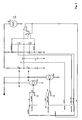
Figure 2 shows a signal diagram which illustrates the mode of operation of the sensor. - The sensor contains two optical measuring sections which are coupled to the inner surface of the pane. The first optical measuring section consists of a light transmitter LED1 in series with a controllable current source CUR1, and a light receiver P1. The second optical measuring section consists of a light transmitter LED2 in series with a controllable current source CUR2, and a light receiver P2. The association between light transmitters and light receivers is symbolized in
Figure 1 respectively by an arrow. The light receivers P1, P2 are arranged in series with each other and with two resistances symmetrically between the two poles of a constant voltage source U. A measuring capacitor C1 is able to be connected by means of a controllable switch SW1 with the connection point between the light receivers P1, P2. The measuring capacitor C1 is additionally connected with the non-inverting input of a comparator COMP, the inverting input of which can be connected via a change-over switch SW4 with one or other of two fixed threshold values INTHIGH and INTLOW. The two fixed threshold values INTHIGH and INTLOW are derived by means of a resistive voltage divider from the constant voltage source U. The change-over switch SW4 is controlled by the output signal STATUS of the comparator COMP. - In the simple embodiment which is shown, the measuring capacitor C1 is used for the integration of the current flow in the light receivers. This measuring capacitor has the function of a current/voltage transformer. In actual implementation, a current/voltage transformer is used with an additional filter and a separate integration circuit.
- A control circuit CONTROL controls the current source CUR1 of the first optical measuring section and the current source CUR2 of the second optical measuring section. To do this, the control circuit connects the control input of the current source CUR1 via a change-over switch SW2 either with signal ground or with a control signal UP_SPEED. In an analogous manner, the control circuit applies either the ground signal or a control signal DOWN_SPEED at the control input of the current source CUR2 via a change-over switch SW3. The change-over switch SW2 is controlled by the signal UP and the change-over switch SW3 is controlled by the signal DOWN. The control circuit CONTROL, to which the output signal STATUS of the comparator COMP is supplied as an input signal, controls the controllable switch SW1 with a signal ENABLE.
- The control circuit CONTROL, for example a programmed microcontroller or an application-specific integrated circuit ASIC, is designed so that it carries out the sequence control which is described in further detail below with the aid of
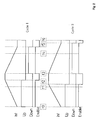
Figure 2 . - In
Figure 2 , firstly "cycle 1" is considered. The sequence consists of continuously repeated measuring cycles. At the start of a measuring process, the measuring capacitor C1 is charged by means of a switch SW6 to the lower threshold value INTLOW. Alternatively, the measuring capacitor C1 can be charged to the upper threshold value INTHIGH at the start by means of a switch SW5. In the diagram ofFigure 2 , however, it is assumed that the cycle begins with a charging process. At the moment t0, the change-over switch SW2 is controlled by the signal UP, in order to connect the control input of the current source CUR1 with the control signal UP_SPEED. This control signal UP_SPEED is set to a suitable default value at the start of the measuring process. At the same time, the switch SW1 is closed by the control signal ENABLE. The light originating from the light transmitter LED1 falls onto the light receiver P1, in which a current flows, by which the measuring capacitor C1 is charged. At the moment t2, the voltage INT at the measuring capacitor C1 reaches the upper threshold value INTHIGH. The comparator COMP changes over and delivers the signal STATUS to the control circuit CONTROL, whereby the control signal ENABLE is terminated. With the start of the charging process at the moment t0, the control circuit starts an internal counter or timer which it stops on completion of the charging process at the moment t2. After a short pause, the current source CUR1 is deactivated at the moment t3 and the current source CUR2 is activated, by the change-over switch SW3 being reversed by the control signal DOWN and the current control signal DOWN_SPEED being thus applied to the control input of the current source CUR2. The light receiver P2 is now provided with current by the light originating from the light transmitter LED2, so that the measuring capacitor C1 is discharged. The voltage INT at the measuring capacitor C1 reaches the lower threshold value INTLOW at the moment t5, so that the comparator COMP switches back. As previously, a counter or timer is started in the control circuit CONTROL at the start of the discharging process at the moment t3, and is stopped at the end of the discharging time at the moment t5. In the subsequent short pause between the moments t5 and t6, an evaluation takes place of the counter readings or timer values in the control circuit CONTROL. A constant cycle duration is achieved by the pause. - Rated values are predetermined internally in the control circuit for the charging time and the discharging time. The actually measured charging times and discharging times are compared with the predetermined rated values. When a deviation is detected, the current control signals UP_SPEED and DOWN_SPEED are re-adjusted for the purposes of regulation. This closed-loop regulation takes place relatively slowly over a plurality of measuring cycles. Momentary deviations between the rated values and the charging and discharging times are interpreted as a disturbance to the balance between the two optical measuring sections, particularly as a wetting of the pane.
- Whereas in
Figure 2 the "cycle 1" is symmetrical, i.e. the charging time is approximately equal to the discharging time, "cycle 2" constitutes a non-symmetrical measuring cycle. The longer discharging time, compared with the charging time, leads to the conclusion that there is a wetting on the second optical measuring section.
Claims (10)
- A method for detecting occurrences of wetting on a pane, particularly the windscreen of a vehicle, in which in successive, continuously repeated measuring cycles:a) in a first cycle section, the current flowing in a light receiver of a first optical measuring section is integrated up to a first threshold value;b) in a second cycle section, the current flowing in a light receiver of a second optical measuring section is integrated to a second threshold value;c) the light transmitters of the optical measuring sections are closed-loop regulated over a plurality of measuring cycles to obtain predetermined rated values of the integration times; andd) detecting a wetting of the pane based on momentary deviations between the rated values and actually measured values of the integration times.
- The method according to Claim1, in which at the start of a measuring process an initialization is carried out, in which the light transmitters are set to an initial value of light intensity.
- The method according to Claim 2, in which the integration takes place by charging and discharging a measuring capacitor, which is charged on initalization to one of the threshold values.
- The method according to any of the preceding claims, in which a pause is included between successive cycle sections.
- A sensor for detecting occurrences of wetting on a pane, particularly the windscreen of a vehicle, with- two optical measuring sections which are adapted to be coupled to the pane, each of which has a controllable light transmitter (LED1, LED2) and a light receiver (P1, P2);- a current/voltage transformer (C1);- a comparator (COMP), the first input (+) of which is connected with the current/voltage transformer, and at the second input (-) of which one or other of two threshold values (INTHIGH, INTLOW) is applied selectively by means of a change-over switch (SW4); and- a control circuit (CONTROL), which controls the light transmitters (LED1, LED2) alternately and connects the current/voltage transformer (C1) selectively with the light receivers (P2, P2) by means of a controllable switch (SW1);in which the control circuit (CONTROL) controls a sequence of successive, continuously repeated measuring cycles:a) in a first cycle section (t0 -t2) the current/voltage transformer (C1) integrates the current flowing in the light receiver (P1) of the first optical measuring section up to the first threshold value (INTHIGH);b) in a second cycle section the current/voltage transformer (C1) integrates the current flowing in the light receiver (P2) of the second optical measuring section to the second threshold value (INTLOW);c) the light transmitters (LED1, LED2) of the optical measuring sections are closed-loop regulated over a plurality of measuring cycles to obtain predetermined rated values of the integration times; andd) wetting of the pane is detected based on momentary deviations between the rated values and actually measured values of the integration times.
- The sensor according to Claim 5, in which the light receivers (P1, P2) of the optical measuring sections are connected symmetrically in series between two fixed voltage potentials.
- The sensor according to Claim 6, in which the measuring capacitor is adapted to be connected with the interconnection node of the light receivers (P1, P2) by means of the controllable switch (SW1).
- The sensor according to any of Claims 5 to 7, in which the light transmitters (LED1, LED2) are each arranged in series with a controllable current source (CUR1, CUR2).
- The sensor according to any of Claims 5 to 8, in which the change-over switch is controlled by the output signal (STATUS) of the comparator (COMP).
- The sensor according to any of Claims 5 to 9, in which the current/voltage transformer is formed by a measuring capacitor (C1) which can be charged to one of the threshold values (INTHIGH, INTLOW) by means of a switch (SW5, SW6) which is able to be controlled by the control circuit (CONTROL).
Priority Applications (1)
| Application Number | Priority Date | Filing Date | Title |
|---|---|---|---|
| PL08007649T PL2017145T3 (en) | 2007-06-12 | 2008-04-18 | Method and sensor for detecting occurrences of wetting on a pane |
Applications Claiming Priority (1)
| Application Number | Priority Date | Filing Date | Title |
|---|---|---|---|
| DE102007027071.4A DE102007027071B4 (en) | 2007-06-12 | 2007-06-12 | Method and sensor for detecting wetting events on a disk |
Publications (3)
| Publication Number | Publication Date |
|---|---|
| EP2017145A2 EP2017145A2 (en) | 2009-01-21 |
| EP2017145A3 EP2017145A3 (en) | 2010-03-17 |
| EP2017145B1 true EP2017145B1 (en) | 2011-12-21 |
Family
ID=39711949
Family Applications (1)
| Application Number | Title | Priority Date | Filing Date |
|---|---|---|---|
| EP08007649A Not-in-force EP2017145B1 (en) | 2007-06-12 | 2008-04-18 | Method and sensor for detecting occurrences of wetting on a pane |
Country Status (11)
| Country | Link |
|---|---|
| US (1) | US7721598B2 (en) |
| EP (1) | EP2017145B1 (en) |
| JP (1) | JP2008309788A (en) |
| KR (1) | KR100970174B1 (en) |
| CN (1) | CN101324673B (en) |
| AT (1) | ATE538008T1 (en) |
| BR (1) | BRPI0801589B1 (en) |
| DE (1) | DE102007027071B4 (en) |
| ES (1) | ES2378340T3 (en) |
| MX (1) | MX2008007510A (en) |
| PL (1) | PL2017145T3 (en) |
Family Cites Families (25)
| Publication number | Priority date | Publication date | Assignee | Title |
|---|---|---|---|---|
| US5059877A (en) * | 1989-12-22 | 1991-10-22 | Libbey-Owens-Ford Co. | Rain responsive windshield wiper control |
| EP0698261B1 (en) | 1993-05-07 | 2003-05-02 | Dennis J. Hegyi | Multi-fonction light sensor for vehicle |
| ES2110651T3 (en) * | 1993-05-24 | 1998-02-16 | Asulab Sa | ULTRASONOUS DETECTION DEVICE, MAINLY FOR AN AUTOMATIC CONTROL WINDSCREEN CLEANING SYSTEM. |
| US5528224A (en) * | 1994-05-03 | 1996-06-18 | Scientific Technology, Inc. | Optical and acoustic weather identification system |
| DE19603553C1 (en) | 1996-02-01 | 1997-04-03 | Bosch Gmbh Robert | Automatically controlled windscreen wiper drive with raindrop sensor |
| DE19621627C1 (en) | 1996-05-30 | 1997-09-18 | Bosch Gmbh Robert | Moisture detector for vehicle windscreen |
| ES2181976T3 (en) * | 1996-12-20 | 2003-03-01 | Asulab Sa | ULTRASOUND DETECTION DEVICE, IN PARTICULAR FOR AN AUTOMATIC CONTROL WINDSHIELD CLEANING SYSTEM. |
| DE19723859A1 (en) * | 1997-06-06 | 1998-12-10 | Bosch Gmbh Robert | Device for detecting the wetting of a pane |
| US6250148B1 (en) * | 1998-01-07 | 2001-06-26 | Donnelly Corporation | Rain sensor mount for use in a vehicle |
| DE19740364A1 (en) * | 1997-09-13 | 1999-03-25 | Bosch Gmbh Robert | Device for operating an optoelectronic rain sensor |
| US5898183A (en) | 1997-10-16 | 1999-04-27 | Libbey-Owens-Ford Co. | Compact moisture sensor with efficient high obliquity optics |
| JP2000075049A (en) * | 1998-08-31 | 2000-03-14 | Matsushita Electric Works Ltd | Detection circuit |
| DE19860214A1 (en) * | 1998-12-24 | 2000-07-13 | Bosch Gmbh Robert | Method and device for detecting a received signal with interference |
| US6114950A (en) * | 1999-05-03 | 2000-09-05 | Specam Technologies, Inc. | Obstacle proximity warning device for vehicles |
| DE50014297D1 (en) * | 1999-06-18 | 2007-06-14 | Valeo Wischersysteme Gmbh | RAIN SENSOR FOR THE DETECTION OF MOISTURE DROPS |
| DE10019112A1 (en) * | 1999-06-18 | 2001-08-16 | Valeo Auto Electric Gmbh | Rain sensor for detecting moisture drops operates light transmission element with signal with lower harmonic content than rectangular wave, preferable sinusoid |
| DE19933641A1 (en) * | 1999-07-17 | 2001-03-08 | Bosch Gmbh Robert | Sensor device for detecting wetting on a pane |
| DE19951832A1 (en) | 1999-10-28 | 2001-05-03 | Valeo Auto Electric Gmbh | Sensor for the detection of drops of moisture and / or dirt particles on a pane and method for operating such a sensor |
| JP3790659B2 (en) * | 2000-05-02 | 2006-06-28 | 株式会社Inax | Optical detector |
| JPWO2002021107A1 (en) * | 2000-09-08 | 2004-01-15 | 日本板硝子株式会社 | Deposit detection device and control device using the same |
| DE10117397A1 (en) | 2001-04-06 | 2002-10-10 | Valeo Auto Electric Gmbh | Sensor for the detection of dirt and / or moisture on the outside of a pane |
| DE10219690A1 (en) * | 2002-05-02 | 2003-11-27 | Ralf Spillecke | Sensor element for the detection of condensation |
| DE10348772A1 (en) | 2003-10-21 | 2005-05-25 | Robert Bosch Gmbh | Measuring unit for a humidity sensor for detecting moisture on a surface, a rain sensor and a method for detecting moisture |
| JP4354860B2 (en) * | 2004-03-30 | 2009-10-28 | 株式会社山武 | Moisture detector |
| JP2008128902A (en) * | 2006-11-22 | 2008-06-05 | Denso Corp | Device and method for detecting rain drop |
-
2007
- 2007-06-12 DE DE102007027071.4A patent/DE102007027071B4/en not_active Expired - Fee Related
-
2008
- 2008-04-18 EP EP08007649A patent/EP2017145B1/en not_active Not-in-force
- 2008-04-18 ES ES08007649T patent/ES2378340T3/en active Active
- 2008-04-18 AT AT08007649T patent/ATE538008T1/en active
- 2008-04-18 PL PL08007649T patent/PL2017145T3/en unknown
- 2008-05-28 BR BRPI0801589-9A patent/BRPI0801589B1/en not_active IP Right Cessation
- 2008-05-30 KR KR1020080050710A patent/KR100970174B1/en active IP Right Grant
- 2008-06-03 US US12/156,675 patent/US7721598B2/en not_active Expired - Fee Related
- 2008-06-11 CN CN200810109956XA patent/CN101324673B/en not_active Expired - Fee Related
- 2008-06-11 MX MX2008007510A patent/MX2008007510A/en active IP Right Grant
- 2008-06-11 JP JP2008152546A patent/JP2008309788A/en active Pending
Also Published As
| Publication number | Publication date |
|---|---|
| DE102007027071A1 (en) | 2008-12-18 |
| PL2017145T3 (en) | 2012-07-31 |
| MX2008007510A (en) | 2009-03-04 |
| CN101324673A (en) | 2008-12-17 |
| DE102007027071B4 (en) | 2019-09-12 |
| BRPI0801589B1 (en) | 2018-04-10 |
| US20080307878A1 (en) | 2008-12-18 |
| ATE538008T1 (en) | 2012-01-15 |
| CN101324673B (en) | 2012-03-07 |
| EP2017145A3 (en) | 2010-03-17 |
| KR20080109618A (en) | 2008-12-17 |
| KR100970174B1 (en) | 2010-07-14 |
| US7721598B2 (en) | 2010-05-25 |
| EP2017145A2 (en) | 2009-01-21 |
| ES2378340T3 (en) | 2012-04-11 |
| JP2008309788A (en) | 2008-12-25 |
| BRPI0801589A2 (en) | 2009-01-27 |
Similar Documents
| Publication | Publication Date | Title |
|---|---|---|
| KR930002467B1 (en) | Device detecting something in a vehicle | |
| US8155903B2 (en) | Method and circuit arrangement for measuring a capacitance | |
| US20080100280A1 (en) | Method And Device For Measuring With Synchronous Detection And Correlated Sampling | |
| CA2032553C (en) | Rain responsive windshield wiper control | |
| JPH0754335B2 (en) | Peak value detection circuit | |
| AU7991798A (en) | Granular material color sorting apparatus | |
| US7356395B2 (en) | Inter-device communication system | |
| US5068540A (en) | Distance measuring apparatus having automatic gain control | |
| US6369378B1 (en) | Device for detecting surface wetness | |
| CN109523739B (en) | Circuit arrangement for a smoke sensor | |
| EP2017145B1 (en) | Method and sensor for detecting occurrences of wetting on a pane | |
| EP1153273B1 (en) | Moisture sensor with automatic emitter intensity control | |
| US5600254A (en) | Process and circuit arrangement for measuring the resistance of a resistance sensor | |
| US8423236B2 (en) | System for detecting a wheel motion | |
| EP2677289B1 (en) | State detecting device | |
| US4354235A (en) | Guidance system detector circuit | |
| EP3741630B1 (en) | Real-time, fine adjustment of driver current of a light emitting device of an optical rain sensor | |
| KR0183804B1 (en) | A current-time converter of auto focus apparatus | |
| EP1014568B1 (en) | Method and device for detecting a receive signal with noise | |
| JPS61146657A (en) | Wiper driving device | |
| SU1530998A1 (en) | Device for measuring angular speed | |
| JPH0434443Y2 (en) | ||
| CN114829889A (en) | Optical to frequency modulator | |
| JPS62179637A (en) | Rain drop detector | |
| JPH04343073A (en) | Simplified system for monitoring voltage |
Legal Events
| Date | Code | Title | Description |
|---|---|---|---|
| PUAI | Public reference made under article 153(3) epc to a published international application that has entered the european phase |
Free format text: ORIGINAL CODE: 0009012 |
|
| PUAI | Public reference made under article 153(3) epc to a published international application that has entered the european phase |
Free format text: ORIGINAL CODE: 0009012 |
|
| AK | Designated contracting states |
Kind code of ref document: A2 Designated state(s): AT BE BG CH CY CZ DE DK EE ES FI FR GB GR HR HU IE IS IT LI LT LU LV MC MT NL NO PL PT RO SE SI SK TR |
|
| AX | Request for extension of the european patent |
Extension state: AL BA MK RS |
|
| PUAL | Search report despatched |
Free format text: ORIGINAL CODE: 0009013 |
|
| AK | Designated contracting states |
Kind code of ref document: A3 Designated state(s): AT BE BG CH CY CZ DE DK EE ES FI FR GB GR HR HU IE IS IT LI LT LU LV MC MT NL NO PL PT RO SE SI SK TR |
|
| AX | Request for extension of the european patent |
Extension state: AL BA MK RS |
|
| 17P | Request for examination filed |
Effective date: 20100426 |
|
| 17Q | First examination report despatched |
Effective date: 20100625 |
|
| AKX | Designation fees paid |
Designated state(s): AT BE BG CH CY CZ DE DK EE ES FI FR GB GR HR HU IE IS IT LI LT LU LV MC MT NL NO PL PT RO SE SI SK TR |
|
| GRAP | Despatch of communication of intention to grant a patent |
Free format text: ORIGINAL CODE: EPIDOSNIGR1 |
|
| RIC1 | Information provided on ipc code assigned before grant |
Ipc: B60S 1/08 20060101AFI20110531BHEP Ipc: G01N 21/45 20060101ALI20110531BHEP |
|
| GRAS | Grant fee paid |
Free format text: ORIGINAL CODE: EPIDOSNIGR3 |
|
| GRAA | (expected) grant |
Free format text: ORIGINAL CODE: 0009210 |
|
| AK | Designated contracting states |
Kind code of ref document: B1 Designated state(s): AT BE BG CH CY CZ DE DK EE ES FI FR GB GR HR HU IE IS IT LI LT LU LV MC MT NL NO PL PT RO SE SI SK TR |
|
| REG | Reference to a national code |
Ref country code: GB Ref legal event code: FG4D |
|
| REG | Reference to a national code |
Ref country code: CH Ref legal event code: EP |
|
| REG | Reference to a national code |
Ref country code: AT Ref legal event code: REF Ref document number: 538008 Country of ref document: AT Kind code of ref document: T Effective date: 20120115 |
|
| REG | Reference to a national code |
Ref country code: IE Ref legal event code: FG4D |
|
| REG | Reference to a national code |
Ref country code: DE Ref legal event code: R096 Ref document number: 602008012093 Country of ref document: DE Effective date: 20120223 |
|
| REG | Reference to a national code |
Ref country code: ES Ref legal event code: FG2A Ref document number: 2378340 Country of ref document: ES Kind code of ref document: T3 Effective date: 20120411 Ref country code: NL Ref legal event code: VDEP Effective date: 20111221 |
|
| PG25 | Lapsed in a contracting state [announced via postgrant information from national office to epo] |
Ref country code: LT Free format text: LAPSE BECAUSE OF FAILURE TO SUBMIT A TRANSLATION OF THE DESCRIPTION OR TO PAY THE FEE WITHIN THE PRESCRIBED TIME-LIMIT Effective date: 20111221 Ref country code: NO Free format text: LAPSE BECAUSE OF FAILURE TO SUBMIT A TRANSLATION OF THE DESCRIPTION OR TO PAY THE FEE WITHIN THE PRESCRIBED TIME-LIMIT Effective date: 20120321 |
|
| LTIE | Lt: invalidation of european patent or patent extension |
Effective date: 20111221 |
|
| PG25 | Lapsed in a contracting state [announced via postgrant information from national office to epo] |
Ref country code: NL Free format text: LAPSE BECAUSE OF FAILURE TO SUBMIT A TRANSLATION OF THE DESCRIPTION OR TO PAY THE FEE WITHIN THE PRESCRIBED TIME-LIMIT Effective date: 20111221 Ref country code: HR Free format text: LAPSE BECAUSE OF FAILURE TO SUBMIT A TRANSLATION OF THE DESCRIPTION OR TO PAY THE FEE WITHIN THE PRESCRIBED TIME-LIMIT Effective date: 20111221 Ref country code: SI Free format text: LAPSE BECAUSE OF FAILURE TO SUBMIT A TRANSLATION OF THE DESCRIPTION OR TO PAY THE FEE WITHIN THE PRESCRIBED TIME-LIMIT Effective date: 20111221 Ref country code: LV Free format text: LAPSE BECAUSE OF FAILURE TO SUBMIT A TRANSLATION OF THE DESCRIPTION OR TO PAY THE FEE WITHIN THE PRESCRIBED TIME-LIMIT Effective date: 20111221 Ref country code: SE Free format text: LAPSE BECAUSE OF FAILURE TO SUBMIT A TRANSLATION OF THE DESCRIPTION OR TO PAY THE FEE WITHIN THE PRESCRIBED TIME-LIMIT Effective date: 20111221 Ref country code: GR Free format text: LAPSE BECAUSE OF FAILURE TO SUBMIT A TRANSLATION OF THE DESCRIPTION OR TO PAY THE FEE WITHIN THE PRESCRIBED TIME-LIMIT Effective date: 20120322 |
|
| PG25 | Lapsed in a contracting state [announced via postgrant information from national office to epo] |
Ref country code: BE Free format text: LAPSE BECAUSE OF FAILURE TO SUBMIT A TRANSLATION OF THE DESCRIPTION OR TO PAY THE FEE WITHIN THE PRESCRIBED TIME-LIMIT Effective date: 20111221 Ref country code: CY Free format text: LAPSE BECAUSE OF FAILURE TO SUBMIT A TRANSLATION OF THE DESCRIPTION OR TO PAY THE FEE WITHIN THE PRESCRIBED TIME-LIMIT Effective date: 20111221 |
|
| PG25 | Lapsed in a contracting state [announced via postgrant information from national office to epo] |
Ref country code: SK Free format text: LAPSE BECAUSE OF FAILURE TO SUBMIT A TRANSLATION OF THE DESCRIPTION OR TO PAY THE FEE WITHIN THE PRESCRIBED TIME-LIMIT Effective date: 20111221 Ref country code: IS Free format text: LAPSE BECAUSE OF FAILURE TO SUBMIT A TRANSLATION OF THE DESCRIPTION OR TO PAY THE FEE WITHIN THE PRESCRIBED TIME-LIMIT Effective date: 20120421 Ref country code: BG Free format text: LAPSE BECAUSE OF FAILURE TO SUBMIT A TRANSLATION OF THE DESCRIPTION OR TO PAY THE FEE WITHIN THE PRESCRIBED TIME-LIMIT Effective date: 20120321 Ref country code: EE Free format text: LAPSE BECAUSE OF FAILURE TO SUBMIT A TRANSLATION OF THE DESCRIPTION OR TO PAY THE FEE WITHIN THE PRESCRIBED TIME-LIMIT Effective date: 20111221 |
|
| REG | Reference to a national code |
Ref country code: PL Ref legal event code: T3 |
|
| PG25 | Lapsed in a contracting state [announced via postgrant information from national office to epo] |
Ref country code: RO Free format text: LAPSE BECAUSE OF FAILURE TO SUBMIT A TRANSLATION OF THE DESCRIPTION OR TO PAY THE FEE WITHIN THE PRESCRIBED TIME-LIMIT Effective date: 20111221 Ref country code: PT Free format text: LAPSE BECAUSE OF FAILURE TO SUBMIT A TRANSLATION OF THE DESCRIPTION OR TO PAY THE FEE WITHIN THE PRESCRIBED TIME-LIMIT Effective date: 20120423 |
|
| REG | Reference to a national code |
Ref country code: AT Ref legal event code: MK05 Ref document number: 538008 Country of ref document: AT Kind code of ref document: T Effective date: 20111221 |
|
| PLBE | No opposition filed within time limit |
Free format text: ORIGINAL CODE: 0009261 |
|
| STAA | Information on the status of an ep patent application or granted ep patent |
Free format text: STATUS: NO OPPOSITION FILED WITHIN TIME LIMIT |
|
| PG25 | Lapsed in a contracting state [announced via postgrant information from national office to epo] |
Ref country code: DK Free format text: LAPSE BECAUSE OF FAILURE TO SUBMIT A TRANSLATION OF THE DESCRIPTION OR TO PAY THE FEE WITHIN THE PRESCRIBED TIME-LIMIT Effective date: 20111221 |
|
| 26N | No opposition filed |
Effective date: 20120924 |
|
| PG25 | Lapsed in a contracting state [announced via postgrant information from national office to epo] |
Ref country code: MC Free format text: LAPSE BECAUSE OF NON-PAYMENT OF DUE FEES Effective date: 20120430 |
|
| REG | Reference to a national code |
Ref country code: CH Ref legal event code: PL |
|
| REG | Reference to a national code |
Ref country code: IE Ref legal event code: MM4A |
|
| REG | Reference to a national code |
Ref country code: DE Ref legal event code: R097 Ref document number: 602008012093 Country of ref document: DE Effective date: 20120924 |
|
| PG25 | Lapsed in a contracting state [announced via postgrant information from national office to epo] |
Ref country code: AT Free format text: LAPSE BECAUSE OF FAILURE TO SUBMIT A TRANSLATION OF THE DESCRIPTION OR TO PAY THE FEE WITHIN THE PRESCRIBED TIME-LIMIT Effective date: 20111221 Ref country code: IE Free format text: LAPSE BECAUSE OF NON-PAYMENT OF DUE FEES Effective date: 20120418 Ref country code: LI Free format text: LAPSE BECAUSE OF NON-PAYMENT OF DUE FEES Effective date: 20120430 Ref country code: CH Free format text: LAPSE BECAUSE OF NON-PAYMENT OF DUE FEES Effective date: 20120430 |
|
| PG25 | Lapsed in a contracting state [announced via postgrant information from national office to epo] |
Ref country code: FI Free format text: LAPSE BECAUSE OF FAILURE TO SUBMIT A TRANSLATION OF THE DESCRIPTION OR TO PAY THE FEE WITHIN THE PRESCRIBED TIME-LIMIT Effective date: 20111221 |
|
| PG25 | Lapsed in a contracting state [announced via postgrant information from national office to epo] |
Ref country code: MT Free format text: LAPSE BECAUSE OF FAILURE TO SUBMIT A TRANSLATION OF THE DESCRIPTION OR TO PAY THE FEE WITHIN THE PRESCRIBED TIME-LIMIT Effective date: 20111221 |
|
| PG25 | Lapsed in a contracting state [announced via postgrant information from national office to epo] |
Ref country code: TR Free format text: LAPSE BECAUSE OF FAILURE TO SUBMIT A TRANSLATION OF THE DESCRIPTION OR TO PAY THE FEE WITHIN THE PRESCRIBED TIME-LIMIT Effective date: 20111221 |
|
| PG25 | Lapsed in a contracting state [announced via postgrant information from national office to epo] |
Ref country code: LU Free format text: LAPSE BECAUSE OF NON-PAYMENT OF DUE FEES Effective date: 20120418 |
|
| PG25 | Lapsed in a contracting state [announced via postgrant information from national office to epo] |
Ref country code: HU Free format text: LAPSE BECAUSE OF FAILURE TO SUBMIT A TRANSLATION OF THE DESCRIPTION OR TO PAY THE FEE WITHIN THE PRESCRIBED TIME-LIMIT Effective date: 20080418 |
|
| REG | Reference to a national code |
Ref country code: FR Ref legal event code: PLFP Year of fee payment: 8 |
|
| PGFP | Annual fee paid to national office [announced via postgrant information from national office to epo] |
Ref country code: ES Payment date: 20150427 Year of fee payment: 8 Ref country code: GB Payment date: 20150427 Year of fee payment: 8 Ref country code: CZ Payment date: 20150413 Year of fee payment: 8 |
|
| PGFP | Annual fee paid to national office [announced via postgrant information from national office to epo] |
Ref country code: PL Payment date: 20150402 Year of fee payment: 8 Ref country code: FR Payment date: 20150417 Year of fee payment: 8 Ref country code: IT Payment date: 20150423 Year of fee payment: 8 |
|
| GBPC | Gb: european patent ceased through non-payment of renewal fee |
Effective date: 20160418 |
|
| REG | Reference to a national code |
Ref country code: FR Ref legal event code: ST Effective date: 20161230 |
|
| PG25 | Lapsed in a contracting state [announced via postgrant information from national office to epo] |
Ref country code: FR Free format text: LAPSE BECAUSE OF NON-PAYMENT OF DUE FEES Effective date: 20160502 Ref country code: CZ Free format text: LAPSE BECAUSE OF NON-PAYMENT OF DUE FEES Effective date: 20160418 Ref country code: GB Free format text: LAPSE BECAUSE OF NON-PAYMENT OF DUE FEES Effective date: 20160418 |
|
| PG25 | Lapsed in a contracting state [announced via postgrant information from national office to epo] |
Ref country code: IT Free format text: LAPSE BECAUSE OF NON-PAYMENT OF DUE FEES Effective date: 20160418 |
|
| PG25 | Lapsed in a contracting state [announced via postgrant information from national office to epo] |
Ref country code: PL Free format text: LAPSE BECAUSE OF NON-PAYMENT OF DUE FEES Effective date: 20160418 |
|
| PG25 | Lapsed in a contracting state [announced via postgrant information from national office to epo] |
Ref country code: ES Free format text: LAPSE BECAUSE OF NON-PAYMENT OF DUE FEES Effective date: 20160419 |
|
| REG | Reference to a national code |
Ref country code: ES Ref legal event code: FD2A Effective date: 20181204 |
|
| REG | Reference to a national code |
Ref country code: DE Ref legal event code: R082 Ref document number: 602008012093 Country of ref document: DE Representative=s name: PRINZ & PARTNER MBB PATENTANWAELTE RECHTSANWAE, DE Ref country code: DE Ref legal event code: R081 Ref document number: 602008012093 Country of ref document: DE Owner name: BCS AUTOMOTIVE INTERFACE SOLUTIONS GMBH, DE Free format text: FORMER OWNER: TRW AUTOMOTIVE ELECTRONICS & COMPONENTS GMBH, 78315 RADOLFZELL, DE |
|
| PGFP | Annual fee paid to national office [announced via postgrant information from national office to epo] |
Ref country code: DE Payment date: 20190416 Year of fee payment: 12 |
|
| REG | Reference to a national code |
Ref country code: DE Ref legal event code: R119 Ref document number: 602008012093 Country of ref document: DE |
|
| PG25 | Lapsed in a contracting state [announced via postgrant information from national office to epo] |
Ref country code: DE Free format text: LAPSE BECAUSE OF NON-PAYMENT OF DUE FEES Effective date: 20201103 |