EP2016878B1 - Pressure cooker equipped with a fixed gripping element on the tank - Google Patents
Pressure cooker equipped with a fixed gripping element on the tank Download PDFInfo
- Publication number
- EP2016878B1 EP2016878B1 EP08447035A EP08447035A EP2016878B1 EP 2016878 B1 EP2016878 B1 EP 2016878B1 EP 08447035 A EP08447035 A EP 08447035A EP 08447035 A EP08447035 A EP 08447035A EP 2016878 B1 EP2016878 B1 EP 2016878B1
- Authority
- EP
- European Patent Office
- Prior art keywords
- pressure cooker
- tank
- pan
- wall
- attachment
- Prior art date
- Legal status (The legal status is an assumption and is not a legal conclusion. Google has not performed a legal analysis and makes no representation as to the accuracy of the status listed.)
- Not-in-force
Links
Images


Classifications
-
- A—HUMAN NECESSITIES
- A47—FURNITURE; DOMESTIC ARTICLES OR APPLIANCES; COFFEE MILLS; SPICE MILLS; SUCTION CLEANERS IN GENERAL
- A47J—KITCHEN EQUIPMENT; COFFEE MILLS; SPICE MILLS; APPARATUS FOR MAKING BEVERAGES
- A47J45/00—Devices for fastening or gripping kitchen utensils or crockery
- A47J45/06—Handles for hollow-ware articles
- A47J45/062—Bowl handles
-
- A—HUMAN NECESSITIES
- A47—FURNITURE; DOMESTIC ARTICLES OR APPLIANCES; COFFEE MILLS; SPICE MILLS; SUCTION CLEANERS IN GENERAL
- A47J—KITCHEN EQUIPMENT; COFFEE MILLS; SPICE MILLS; APPARATUS FOR MAKING BEVERAGES
- A47J27/00—Cooking-vessels
- A47J27/08—Pressure-cookers; Lids or locking devices specially adapted therefor
- A47J27/0804—Locking devices
- A47J27/0808—Locking devices of the bridge-type
-
- Y—GENERAL TAGGING OF NEW TECHNOLOGICAL DEVELOPMENTS; GENERAL TAGGING OF CROSS-SECTIONAL TECHNOLOGIES SPANNING OVER SEVERAL SECTIONS OF THE IPC; TECHNICAL SUBJECTS COVERED BY FORMER USPC CROSS-REFERENCE ART COLLECTIONS [XRACs] AND DIGESTS
- Y10—TECHNICAL SUBJECTS COVERED BY FORMER USPC
- Y10S—TECHNICAL SUBJECTS COVERED BY FORMER USPC CROSS-REFERENCE ART COLLECTIONS [XRACs] AND DIGESTS
- Y10S220/00—Receptacles
- Y10S220/912—Cookware, i.e. pots and pans
Definitions
- the present invention relates to the general technical field of cooking utensils of the type cooking vessels, and in particular to the pressure cookers sector, that is to say cooking pots under pressure to ensure the cooking under pressure of steam food contained within them.
- a pressure cooker of this type is described in EP 1 535 551 A . They usually consist of a metal bowl for food and a lid, also metal, to be reported and locked on the tank to form with the latter a sealed cooking chamber.
- Such a pressure cooker is intended to be subjected to the influence of a heating source (such as a cooking plate) so as to allow the rise in pressure and temperature of the enclosure and thus the cooking under pressure of the food contained in the latter.
- a heating source such as a cooking plate
- the tank of these known pressure cookers is usually provided with a pair of handles, fixed on the side wall of the tank so that diametrically opposed to each other, said handles extending from the side wall of the tank to the outside of the latter.
- These handles allow the user to manipulate not only the tank alone but also and especially the complete pressure cooker (formed by the assembly of the tank and lid), especially when said pressure cooker is filled with cooked or cooking food possibly accompanied by a cooking liquid.
- the metal vessel is generally obtained by metallurgical manufacturing processes, such as stamping.
- the handles are usually made of thermosetting thermally insulating material, to prevent the user from getting burned by grabbing the handles while the tank is hot.
- the implementation of a metal bridge to fix each handle on the tank contributes to increase the complexity and cost of manufacturing operations of the pressure cooker, insofar as it requires additional raw material to make the trigger guard (The said raw material is moreover, in the case of steel, more and more rare and expensive) and precise welding operations requiring not only a specific material but also a skilled workforce.
- the head of the assembly screw of the handle on the bridge is, given the assembly made (centripetal screwing), necessarily accessible from outside the pressure cooker.
- the screw is itself in direct contact with the bridge in which it is screwed, said bridge itself being in direct contact with the wall of the tank to which it is welded, said tank being subjected to the influence of the heating source. Consequently, by a thermal conduction effect, the screw head can be hot and thus constitute a source of serious burn accident for the user who would come to touch it inadvertently by wanting to grab the handles.
- the objects assigned to the invention therefore aim to remedy the various disadvantages listed above and to propose a new domestic pressure cooker whose construction is particularly simple, reliable and cheap.
- Another object of the invention is to propose a new domestic pressure cooker whose general principle of construction is well known and tested.
- Another object of the invention is to propose a new domestic pressure cooker of particularly robust design.
- Another object of the invention is to propose a new domestic pressure cooker offering excellent safety of use.
- the pressure cooker 1 according to the invention is intended to ensure the cooking of different foods under pressure in a domestic context. It therefore forms a domestic pressure cooker.
- the pressure cooker 1 according to the invention is therefore a kitchen utensil having a portable character (that is to say manually movable) and independent.
- the pressure cooker 1 is a thermally passive kettle, designed to increase pressure under the effect of a heating source which is external to it, such as a hob.
- the pressure cooker 1 comprises a vessel 2 forming a cooking vessel and advantageously having substantially a symmetry of revolution along an axis X-X '.
- the adjective " axial " will refer to the direction of this axis of symmetry X-X 'direction which is similar to the vertical direction when the device is in normal operation.
- the tank 2 is for example and conventionally manufactured by stamping a blank of a metallic material such as aluminum or stainless steel.
- the pressure cooker 1 also comprises a lid 3 intended to be attached to said tank 2 to form with it a cooking chamber preferably substantially sealed, that is to say sufficiently hermetic to allow a rise in pressure within it.
- the enclosure formed by the combination of the tank 2 and the lid 3 is designed to allow a significant increase in pressure within it, so that during cooking, the pressure in the chamber can be significantly greater than the atmospheric pressure, and for example exceed said atmospheric pressure of a value greater than or equal to 10 kPa, and preferably greater than or equal to 20 kPa. It is also quite possible, in order to allow a very fast and efficient cooking, that the chamber is designed so that the pressure prevailing within it can exceed the atmospheric pressure by a value substantially between 40 and 110 kPa, and preferably substantially between 50 and 100 kPa.
- the lid 3 preferably affects a general disc shape, complementary to the shape of the tank 2.
- the cover 3 can be locked or unlocked at will on the tank 2, the lid 3 of the lock allowing the enclosure to increase pressure without escaping the lid 3 under the effect of pressure.
- the pressure cooker 1 preferably comprises a locking / unlocking means 4 of the lid 3 on the tank 2.
- the locking / unlocking means 4 may be of any type known to those skilled in the art, and is conventionally likely to evolve between a lid 3 locking configuration relative to the tank 2 (illustrated in particular in the figure 3 ) in which the lid 3 is secured to the tank 2, and an unlocking configuration of the lid 3 relative to the tank 2 (illustrated in particular in FIG. figure 4 ), in which the lid 3 can be freely separated from the tank 2.
- the locking / unlocking means 4 comprises at least one locking element 5, 6 of the cover 3 relative to the tank 2, the said at least one locking element 5, 6 being movably mounted on the cover 2, substantially in radial translation with respect to the axis XX 'by means of at least one corresponding drive means between an indexed locking position (illustrated for example in FIG. figure 3 ) and an indexed unlocking position (illustrated for example in figure 4 ).
- said at least one locking element 5, 6 may comprise a jaw intended to grip the peripheral edges of the tank 2 and the lid 3.
- Said jaw may be in the form of a metal plate , U-shaped at its outer end, as is well known to those skilled in the art.
- the pressure cooker 1 comprises two locking elements 5, 6 constituted by bifurcated segments each having two respective locking bolts 5A, 5B, 6A, 6B, said segments being positioned opposite, diametrically opposite the general axis of symmetry XX 'of the apparatus.
- the drive means for each bifurcated segment consists of a respective driving arm, which carrying arm can for example come from material with the corresponding segment.
- Locking openings 50A, 50B, 60A, 60B complementary to the bolts 5A, 5B, 6A, 6B are formed in the tank 2, so that the locking of the lid 3 corresponds to the engagement of the bolts 5A, 5B, 6A, 6B in respective complementary openings 50A, 50B, 60A, 60B (cf. figure 3 ), in the manner of a bolt / strike lock system, to substantially prevent any movement of the cover 3 relative to the tank 2, while the unlocking of the cover 3 corresponds to the retraction and disengagement of the bolts 5A, 5B, 6A, 6B out of lights 50A, 50B, 60A, 60B corresponding so that said bolts do not cooperate with said lights 50A, 50B, 60A, 60B.
- the locking / unlocking means 4 of the cover 3 relative to the tank 2 is however not limited to a segment or jaw system and may for example be based on other principles, well known as such, of the average kind bayonet locking / unlocking or yoke locking / unlocking means.
- the pressure cooker 1 also comprises at least one gripping member 20 fixed on the tank 2, and preferably fixed directly on the wall of the tank 2.
- the gripping member 20 is designed to allow user to handle not only the tank 2 only but also and especially the pressure cooker 1 complete (formed of the assembly of the tank 2 and the lid 3), especially when said pressure cooker 1 is filled with cooked food or cooking possibly accompanied by a cooking liquid.
- the gripping member 20 is therefore designed to allow easy and firm manual gripping of the pressure cooker 1, so that the user can move manually and at will his pressure cooker 1 without risk of the latter escape him.
- the gripping member 20 comprises at least one handle 21 extending substantially from and towards the outside of the tank 2, radially with respect to the axis X-X '.
- the gripping member 20 is fixed on the tank 2 by means of a fastening means 20A making it possible to establish a mechanical connection, and preferably a mechanical connection, between the gripping member 20 and the tank 2.
- a fastening means 20A making it possible to establish a mechanical connection, and preferably a mechanical connection, between the gripping member 20 and the tank 2.
- the gripping member 20 is distinct and independent of the tank 2, and is attached and fixed on the latter, using the fastening means 20A.
- the attachment means 20A thus makes it possible to secure, that is to say to fix the gripping member 20 directly on the tank 2.
- the attachment means 20A comprises at least one attachment hole 200A passing through the wall of the tank 2, that is to say extending through the entire thickness E of said vessel wall.
- the fixing hole 200A is, according to the invention, positioned on the wall of the tank 2 to not communicate with the inside of the cooking chamber. This means that if the fixing hole 200A is provided through the wall of the tank 2 so as to completely cross the latter, it is located at a location of the tank wall 2 which does not contribute to forming, with the lid 3, the sealed cooking chamber.
- the attachment means 20A also comprises a fastening element 201A, connected to the gripping member 20 and extending through the fixing hole 200A, to ensure the fastening of the fastener member. gripping 20 to the wall of the tank 2.
- the fastening element 201A is thus threaded into the fixing hole 200A, so as to pass through the wall of the tank over the entire thickness E of the latter.
- the fastening element 201A extends, through the fixing orifice 200A, between an outer end 202A secured to the gripping member 20 and an inner end 203A provided with a head abutting against the tank 2, around the orifice 200A, as shown in the figures.
- the invention is therefore based on a principle of very simple attachment of the gripping member 20 to the wall of the vessel 2, this fastening principle being based on the cooperation of a hole passing through the vessel wall from one side to the other. a fastening element passing through said hole.
- the invention provides for positioning the fixing orifice 200A in a zone of the tank wall 2 which does not contribute directly to forming the cooking chamber, so that any sealing problem is therefore discarded.
- the invention makes it possible to obtain a fixing of the gripping member 20 to the tank 2 by the simple implementation of a fixing orifice made directly in and through the wall of the tank 2 (and not through an adjoining room attached to the tank), while ensuring a durable seal of the cooking chamber.
- the fixing orifice 20A is formed through the side wall 2B of the tank 2, said orifice 200A extending through the entire thickness E of the side wall 2B, between the internal face 30 of the side wall 2B , facing the inside of the tank 2, and the outer face 31 of said side wall 2B, opposite the inner face 30 and located towards the outside of the pressure cooker 1.
- the pressure cooker 1 comprises two handles 21, 22 disposed on the tank 2 diametrically opposite to the axis of symmetry X-X '.
- the two handles 21, 22 are preferably identical, and each comprise for example a base 210, 220 fixed directly to the tank wall 2 and from which extends a loop 211, 221 which comes from material with the base and is intended to be entered manually by the user. More specifically, in the example illustrated in the figures, each handle 21, 22 is attached directly against the outer face 31 of the side wall 2B of the vessel 2.
- Each handle 21, 22 is preferably attached to the vessel 2 of the same way, that is to say by means of a corresponding fastening means comprising a fixing hole and a fastening element according to the foregoing description.
- the fastening element 201A comprises at least one screw 40 provided with a head 40A and a threaded rod 40B extending from said head 40A through the fixing orifice 200A.
- the gripping member 20 is advantageously provided with a threaded hole 50 in which is screwed the threaded rod 40B, the head 40A (whose diameter is greater than that of the rod 40B) being positioned inside the the tank 2 and bearing against the latter, that is to say against the inner face 30 of the side wall 2B.
- the tapped hole 50 which is for example made in the base 220 of the handle 22, is blind.
- the tapped hole 50 does not open towards the outside of the apparatus, so that once the handle 22 is assembled on the tank 2, the attachment means 20A is completely hidden and inaccessible to the
- the threaded rod 40B is entirely enclosed in the handle 22, which is preferably made of thermally insulating material, so as to provide complete thermal insulation to the user.
- each handle 21, 22 is in the form of an integral part made of a thermosetting material, obtained for example by molding, it being understood that any other material satisfying the thermal stresses can be envisaged (metallic material by example).
- the tapped hole 50 is preferably formed directly in the material constituting the base 220, by any known machining technique. However, it is quite possible to provide, according to an alternative solution, the threaded hole 50 is made in an insert, for example metal, said insert being itself integrated in the base 220 for example by screwing or overmolding.
- the lid 3 is designed to dock the side wall 2B of the tank 2 in a substantially sealed interface zone 60 to form the cooking chamber.
- the cooking chamber is thus delimited by the bottom 2A, the cover 3, the interface zone 60 and the portion 70 of the lateral wall extending between the bottom 2A and the interface zone 60.
- 200A is provided outside this portion 70.
- the orifice of 200A attachment is for example formed in a portion 80 of the side wall extending from the portion 70 contributing to delimit the enclosure, said portion 80 extending from the portion 70 to the upper opening 2C .
- the cooking chamber extends, in the vertical direction defined by the axis X-X ', between the bottom 2A and a sealing line corresponding to the interface zone between the cover 3 and the tank 2, the fixing orifice 200A being formed in the wall of the tank 2 outside the zone delimited between the bottom 2A and the interface zone 60.
- the fixing orifice 200A is provided on the tank wall 2, at an altitude greater than that of the interface zone 60 forming a sealing line (with respect to a reference frame whose origin corresponds for example to the bottom 2A).
- the cover 3 comprises a falling edge 3B, extending substantially downwardly from a main body 3A itself intended to be parallel to the bottom 2A.
- the falling edge 3B is intended to be introduced into the tank 2, inside the latter, to come into sealing contact with the inner face 30 of the side wall 2B.
- the falling edge 3B is provided with a seal 3C through which the sealing contact is made between the tank 2 and the lid 3.
- the latter has a recess 2D against which bears the seal 3C.
- the recess 2D is a substantially frustoconical portion of the side wall 2B which connects two other portions of said side wall 2B, these two other portions being each substantially vertical but of different diameters.
- the tank 2 thus flares from the bottom 2A.
Abstract
Description
La présente invention se rapporte au domaine technique général des ustensiles de cuisine du type récipients de cuisson, et en particulier au secteur des autocuiseurs, c'est à dire des marmites de cuisson sous pression destinées à assurer la cuisson sous pression de vapeur des aliments contenus en leur sein.The present invention relates to the general technical field of cooking utensils of the type cooking vessels, and in particular to the pressure cookers sector, that is to say cooking pots under pressure to ensure the cooking under pressure of steam food contained within them.
La présente invention concerne plus particulièrement un autocuiseur domestique comprenant :
- une cuve qui comprend elle-même une paroi,
- un couvercle destiné à être rapporté sur la cuve pour former avec cette dernière une enceinte de cuisson sensiblement étanche,
- et au moins un organe de préhension, fixé sur la cuve à l'aide d'un moyen d'attache.
- a tank which itself comprises a wall,
- a lid intended to be attached to the tank to form with the latter a substantially sealed cooking chamber,
- and at least one gripping member fixed to the tank by means of a fastening means.
Les autocuiseurs domestiques sont bien connus. Un autocuiseur de ce type est décrit dans
Un tel autocuiseur est destiné à être soumis à l'influence d'une source de chauffe (comme par exemple une plaque de cuisson) de manière à permettre la montée en pression et en température de l'enceinte et ainsi la cuisson sous pression des aliments contenus dans cette dernière.Such a pressure cooker is intended to be subjected to the influence of a heating source (such as a cooking plate) so as to allow the rise in pressure and temperature of the enclosure and thus the cooking under pressure of the food contained in the latter.
La cuve de ces autocuiseurs connus est habituellement pourvue d'une paire de poignées, fixées sur la paroi latérale de la cuve de manière diamétralement opposées l'une par rapport à l'autre, lesdites poignées s'étendant à partir de la paroi latérale de la cuve vers l'extérieur de cette dernière. Ces poignées permettent à l'utilisateur de manipuler non seulement la cuve seule mais également et surtout l'autocuiseur complet (formé de l'assemblage de la cuve et du couvercle), en particulier lorsque ledit autocuiseur est rempli d'aliments cuits ou à cuire, accompagnés éventuellement d'un liquide de cuisson.The tank of these known pressure cookers is usually provided with a pair of handles, fixed on the side wall of the tank so that diametrically opposed to each other, said handles extending from the side wall of the tank to the outside of the latter. These handles allow the user to manipulate not only the tank alone but also and especially the complete pressure cooker (formed by the assembly of the tank and lid), especially when said pressure cooker is filled with cooked or cooking food possibly accompanied by a cooking liquid.
La cuve métallique est généralement obtenue par des procédés de fabrication métallurgiques, tels que l'emboutissage. Les poignées sont quant à elles habituellement réalisées en un matériau thermodurcissable thermiquement isolant, afin d'éviter que l'utilisateur ne se brûle en saisissant les poignées alors que la cuve est chaude.The metal vessel is generally obtained by metallurgical manufacturing processes, such as stamping. The handles are usually made of thermosetting thermally insulating material, to prevent the user from getting burned by grabbing the handles while the tank is hot.
La différence de nature entre la cuve (obtenue par emboutissage d'un flan métallique) et la poignée (obtenue par moulage d'une matière thermodurcissable) interdit bien entendu l'obtention en une seule et même opération d'une cuve équipée de ses poignées. Il est donc nécessaire de rapporter les poignées sur la cuve et de les fixer à cette dernière.The difference in nature between the tank (obtained by stamping a metal blank) and the handle (obtained by molding a thermosetting material) of course prohibits obtaining in a single operation a tank equipped with its handles . It is therefore necessary to bring the handles on the tank and fix them to it.
A cette fin, il est connu de fixer sur la face extérieure de la paroi latérale de la cuve un pontet métallique, par exemple par soudure. La poignée est ensuite assemblée sur le pontet à l'aide d'une vis métallique, cette dernière traversant la poignée pour venir se visser dans le pontet de manière centripète par rapport à l'axe de symétrie général de la cuve (de l'extérieur vers l'intérieur).To this end, it is known to fix on the outer face of the side wall of the vessel a metal bridge, for example by welding. The handle is then assembled on the bridge by means of a metal screw, the latter passing through the handle to be screwed into the bridge centripetally with respect to the general axis of symmetry of the tank (from the outside towards the inside).
Un tel autocuiseur, s'il donne généralement satisfaction, n'en présente pas moins un certain nombre d'inconvénients.Such a pressure cooker, if it generally gives satisfaction, nonetheless presents a number of disadvantages.
Ainsi, la mise en oeuvre d'un pontet métallique pour fixer chaque poignée sur la cuve contribue à augmenter la complexité et le coût des opérations de fabrication de l'autocuiseur, dans la mesure où elle nécessite un supplément de matière première pour réaliser le pontet (ladite matière première étant de surcroît, s'agissant d'acier, de plus en plus rare et chère) et des opérations de soudure précises nécessitant non seulement un matériel spécifique mais également une main d'oeuvre qualifiée.Thus, the implementation of a metal bridge to fix each handle on the tank contributes to increase the complexity and cost of manufacturing operations of the pressure cooker, insofar as it requires additional raw material to make the trigger guard (The said raw material is moreover, in the case of steel, more and more rare and expensive) and precise welding operations requiring not only a specific material but also a skilled workforce.
De plus, la tête de la vis d'assemblage de la poignée sur le pontet est, compte-tenu du montage réalisé (vissage centripète), nécessairement accessible de l'extérieur de l'autocuiseur. Or, la vis est elle-même en contact direct avec le pontet dans lequel elle est vissée, ledit pontet étant lui-même en contact direct avec la paroi de la cuve à laquelle il est soudé, ladite cuve étant quant à elle soumise à l'influence de la source de chauffe. Par conséquent, par un effet de conduction thermique, la tête de vis peut être brûlante et constituer à ce titre une source d'accident grave par brûlure pour l'utilisateur qui viendrait à la toucher malencontreusement en voulant justement saisir les poignées.In addition, the head of the assembly screw of the handle on the bridge is, given the assembly made (centripetal screwing), necessarily accessible from outside the pressure cooker. However, the screw is itself in direct contact with the bridge in which it is screwed, said bridge itself being in direct contact with the wall of the tank to which it is welded, said tank being subjected to the influence of the heating source. Consequently, by a thermal conduction effect, the screw head can be hot and thus constitute a source of serious burn accident for the user who would come to touch it inadvertently by wanting to grab the handles.
C'est pourquoi il est nécessaire de conformer la poignée de manière à éviter que l'utilisateur ne puisse malencontreusement toucher la tête de vis en saisissant les poignées. Une telle conformation, qui est imposée par des normes de sécurité applicables dans de nombreux pays, met en jeu un surplus de matière qui vient renchérir le coût de l'autocuiseur, alors que ce dernier est un ustensile de grande consommation qui doit être accessible au plus grand nombre. Ces exigences normatives constituent en outre une contrainte de conception supplémentaire qui peut interdire de donner aux poignées une forme plus esthétique, ou du moins plus attractive ou originale, que celle de poignées connues.This is why it is necessary to conform the handle so as to prevent the user from accidentally touching the screw head by grasping the handles. Such a conformation, which is imposed by safety standards applicable in many countries, involves a surplus of material which increases the cost of the pressure cooker, while the latter is a consumer appliance that must be accessible to the consumer. greater number. These normative requirements also constitute an additional design constraint that may prohibit giving the handles a shape that is more aesthetic, or at least more attractive or original, than that of known handles.
Les objets assignés à l'invention visent en conséquence à porter remède aux divers inconvénients énumérés précédemment et à proposer un nouvel autocuiseur domestique dont la construction est particulièrement simple, fiable et bon marché.The objects assigned to the invention therefore aim to remedy the various disadvantages listed above and to propose a new domestic pressure cooker whose construction is particularly simple, reliable and cheap.
Un autre objet de l'invention vise à proposer un nouvel autocuiseur domestique dont le principe général de construction est bien connu et éprouvé.Another object of the invention is to propose a new domestic pressure cooker whose general principle of construction is well known and tested.
Un autre objet de l'invention vise à proposer un nouvel autocuiseur domestique de conception particulièrement robuste.Another object of the invention is to propose a new domestic pressure cooker of particularly robust design.
Un autre objet de l'invention vise à proposer un nouvel autocuiseur domestique offrant une excellente sécurité d'utilisation.Another object of the invention is to propose a new domestic pressure cooker offering excellent safety of use.
Les objets assignés à l'invention sont atteints à l'aide d'un autocuiseur domestique comprenant :
- une cuve qui comprend elle-même une paroi,
- un couvercle destiné à être rapporté sur la cuve pour former avec cette dernière une enceinte de cuisson sensiblement étanche,
- au moins un organe de préhension, fixé sur la cuve à l'aide d'un moyen d'attache,
- un orifice de fixation traversant la paroi de la cuve, ledit orifice de fixation étant positionné sur la paroi de la cuve pour ne pas communiquer avec l'intérieur de l'enceinte de cuisson,
- et un élément de fixation, relié à l'organe de préhension et s'étendant à travers l'orifice de fixation.
- a tank which itself comprises a wall,
- a lid intended to be attached to the tank to form with the latter a substantially sealed cooking chamber,
- at least one gripping member fixed to the tank by means of a fastening means,
- a fixing orifice passing through the wall of the tank, said fixing orifice being positioned on the wall of the tank so as not to communicate with the interior of the cooking chamber,
- and a fastener connected to the gripper and extending through the fastener.
D'autres particularités et avantages de l'invention apparaîtront et ressortiront plus en détails à la lecture de la description faite ci-après, en référence aux dessins annexés, donnés à titre d'exemple illustratif et non limitatif dans lesquels :
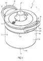
- La
figure 1 illustre, selon une vue générale en perspective, un autocuiseur domestique conforme à l'invention. - La
figure 2 illustre, selon une vue générale en perspective partiellement coupée, selon deux plans de coupe sensiblement perpendiculaires, l'autocuiseur de lafigure 1 . - La
figure 3 illustre, selon une vue de dessus partiellement écorchée et coupée, l'autocuiseur desfigures 1 et2 avec le couvercle verrouillé sur la cuve. - La
figure 4 illustre, selon une vue de dessus partiellement écorchée et coupée, l'autocuiseur desfigures 1 à 3 avec son couvercle déverrouillé sur la cuve. - La
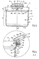
figure 5 illustre, selon une vue latérale en coupe, la cuve de l'autocuiseur illustré auxfigures 1 à 4 . - La
figure 6 illustre, selon une vue en coupe selon la ligne A-A de lafigure 5 , un détail agrandi de réalisation de la cuve illustrée à lafigure 5 . - La
figure 7 illustre, selon une vue en perspective coupée, un détail de réalisation de d'autocuiseur illustré auxfigures 1 à 4 .
- The
figure 1 illustrates, in a general perspective view, a domestic pressure cooker according to the invention. - The
figure 2 illustrates, according to a general perspective view partially cut, according to two substantially perpendicular cutting planes, the pressure cooker of thefigure 1 . - The
figure 3 illustrates, according to a top view partially cut and cut, the pressure cooker offigures 1 and2 with the lid locked on the tank. - The
figure 4 illustrates, according to a top view partially cut and cut, the pressure cooker ofFigures 1 to 3 with its lid unlocked on the tank. - The
figure 5 illustrates, in a sectional side view, the tank of the pressure cooker illustrated in FIGS.Figures 1 to 4 . - The
figure 6 illustrates, according to a sectional view along the line AA of thefigure 5 , an enlarged detail of realization of the tank illustrated in thefigure 5 . - The
figure 7 illustrates, in a cut perspective view, a detail of production of pressure cooker illustrated in FIGS.Figures 1 to 4 .
L'autocuiseur 1 conforme à l'invention est destiné à assurer la cuisson de différents aliments sous pression dans un contexte domestique. Il forme donc à ce titre un autocuiseur domestique.The
L'autocuiseur 1 conforme à l'invention est donc un ustensile de cuisine présentant un caractère portatif (c'est à dire déplaçable manuellement) et indépendant.The
Avantageusement, l'autocuiseur 1 conforme à l'invention constitue une marmite passive thermiquement, conçue pour monter en pression sous l'effet d'une source de chauffe qui lui est extérieure, telle qu'une plaque de cuisson.Advantageously, the
De façon préférentielle, l'autocuiseur 1 conforme à l'invention comprend une cuve 2 formant récipient de cuisson et présentant avantageusement sensiblement une symétrie de révolution selon un axe X-X'. Par la suite, l'adjectif « axial » se référera à la direction de cet axe de symétrie X-X', direction qui s'apparente à la direction verticale lorsque l'appareil est en fonctionnement normal. La cuve 2 est par exemple et de manière classique fabriquée par emboutissage d'un flan en matériau métallique tel que l'aluminium ou l'acier inoxydable.Preferably, the
La cuve 2 comprend ainsi une paroi, laquelle paroi comprend elle-même, dans l'exemple de réalisation illustré :
- un fond 2A, qui présente par exemple une forme discoïde,
- et une paroi latérale 2B, qui s'élève à partir et à la périphérie dudit fond 2A ; ladite paroi latérale 2B présente une forme sensiblement annulaire et délimite une ouverture supérieure 2C permettant d'introduire des aliments dans la cuve 2, en vue de les y cuire ; ladite paroi latérale 2B présente également une
face interne 30 située en regard de l'intérieur de la cuve 2 et uneface externe 31 opposée.
- a
bottom 2A, which has for example a discoid shape, - and a
side wall 2B, which rises from and at the periphery of saidbottom 2A; saidside wall 2B has a substantially annular shape and delimits an upper opening 2C for introducing food into thetank 2, for the purpose of cooking there; saidside wall 2B also has aninner face 30 facing the inside of thetank 2 and an oppositeouter face 31.
L'autocuiseur 1 conforme à l'invention comprend également un couvercle 3 destiné à être rapporté sur ladite cuve 2 pour former avec cette dernière une enceinte de cuisson de préférence sensiblement étanche, c'est-à-dire suffisamment hermétique pour permettre une montée en pression en son sein.The
Ainsi, l'enceinte formée par la réunion de la cuve 2 et du couvercle 3 est conçue pour permettre une augmentation significative de pression en son sein, de sorte que pendant la cuisson, la pression régnant dans l'enceinte peut être nettement supérieure à la pression atmosphérique, et par exemple excéder ladite pression atmosphérique d'une valeur supérieure ou égale à 10 kPa, et de préférence supérieure ou égale à 20 kPa. Il est également tout à fait envisageable, afin de permettre une cuisson très rapide et efficace, que l'enceinte soit conçue pour que la pression régnant en son sein puisse excéder la pression atmosphérique d'une valeur sensiblement comprise entre 40 et 110 kPa, et de préférence sensiblement comprise entre 50 et 100 kPa.Thus, the enclosure formed by the combination of the
Le couvercle 3 affecte préférentiellement une forme générale discoïde, complémentaire de la forme de la cuve 2.The
Avantageusement, le couvercle 3 peut être verrouillé ou déverrouillé à volonté sur la cuve 2, le verrouillage du couvercle 3 permettant à l'enceinte de monter en pression sans échappement du couvercle 3 sous l'effet de la pression. A cette fin, l'autocuiseur 1 comprend préférentiellement un moyen de verrouillage / déverrouillage 4 du couvercle 3 sur la cuve 2. Le moyen de verrouillage / déverrouillage 4 peut être de tout type connu de l'homme du métier, et est de façon classique susceptible d'évoluer entre une configuration de verrouillage du couvercle 3 relativement à la cuve 2 (illustrée notamment à la
De préférence, le moyen de verrouillage / déverrouillage 4 comprend au moins un élément de verrouillage 5, 6 du couvercle 3 relativement à la cuve 2, ledit au moins un élément de verrouillage 5, 6 étant monté mobile, sur le couvercle 2, sensiblement en translation radiale par rapport à l'axe X-X' par l'intermédiaire d'au moins un moyen d'entraînement correspondant entre une position indexée de verrouillage (illustrée par exemple à la
Selon un mode de réalisation non illustré, ledit au moins un élément de verrouillage 5, 6 peut comprendre une mâchoire destinée à enserrer les bords périphériques de la cuve 2 et du couvercle 3. Ladite mâchoire peut se présenter sous la forme d'une plaque métallique, profilée en U à son extrémité extérieure, tel que cela est bien connu en soi de l'homme du métier.According to a non-illustrated embodiment, said at least one
Selon le mode de réalisation alternatif préféré illustré aux figures, l'autocuiseur 1 conforme à l'invention comprend deux éléments de verrouillage 5, 6 constitués par des segments bifides présentant chacun deux pênes de verrouillage respectifs 5A, 5B, 6A, 6B lesdits segments étant positionnés en vis-à-vis, de manière diamétralement opposée en regard de l'axe de symétrie général X-X' de l'appareil.According to the preferred alternative embodiment illustrated in the figures, the
Avantageusement, le moyen d'entraînement pour chaque segment bifide consiste en un bras entraîneur respectif, lequel bras entraîneur peut par exemple venir de matière avec le segment correspondant.Advantageously, the drive means for each bifurcated segment consists of a respective driving arm, which carrying arm can for example come from material with the corresponding segment.
Des ouvertures de verrouillage 50A, 50B, 60A, 60B complémentaires aux pênes 5A, 5B, 6A, 6B sont ménagées dans la cuve 2, de telle sorte que le verrouillage du couvercle 3 correspond à l'engagement des pênes 5A, 5B, 6A, 6B dans les ouvertures complémentaires respectives 50A, 50B, 60A, 60B (cf.
Le moyen de verrouillage / déverrouillage 4 du couvercle 3 relativement à la cuve 2 n'est cependant pas limité à un système à segments ou à mâchoires et peut par exemple reposer sur d'autres principes, bien connus en tant que tels, du genre moyen de verrouillage / déverrouillage à baïonnettes ou moyen de verrouillage / déverrouillage à étrier.The locking / unlocking
Conformément à l'invention, l'autocuiseur 1 comprend également au moins un organe de préhension 20 fixé sur la cuve 2, et de préférence fixé directement sur la paroi de la cuve 2. L'organe de préhension 20 est conçu pour permettre à l'utilisateur de manipuler non seulement la cuve 2 seule mais également et surtout l'autocuiseur 1 complet (formé de l'assemblage de la cuve 2 et du couvercle 3), en particulier lorsque ledit autocuiseur 1 est rempli d'aliments cuits ou à cuire, accompagnés éventuellement d'un liquide de cuisson. L'organe de préhension 20 est donc conçu pour permettre une prise manuelle aisée et ferme de l'autocuiseur 1, de manière à ce que l'utilisateur puisse déplacer manuellement et à volonté son autocuiseur 1 sans risque de voir ce dernier lui échapper. De préférence et comme illustré aux figures, l'organe de préhension 20 comprend au moins une poignée 21 s'étendant sensiblement à partir et vers l'extérieur de la cuve 2, radialement par rapport à l'axe X-X'.According to the invention, the
L'organe de préhension 20 est fixé sur la cuve 2 à l'aide d'un moyen d'attache 20A permettant d'établir une liaison mécanique, et de préférence une liaison mécanique d'encastrement, entre l'organe de préhension 20 et la cuve 2. De préférence, l'organe de préhension 20 est distinct et indépendant de la cuve 2, et est rapporté et fixé sur cette dernière, à l'aide du moyen d'attache 20A. Le moyen d'attache 20A permet donc d'assujettir, c'est-à-dire de fixer l'organe de préhension 20 directement sur la cuve 2.The gripping
Selon l'invention, le moyen d'attache 20A comprend au moins un orifice de fixation 200A traversant la paroi de la cuve 2, c'est-à-dire s'étendant à travers toute l'épaisseur E de ladite paroi de cuve.According to the invention, the attachment means 20A comprises at least one
L'orifice de fixation 200A est, conformément à l'invention, positionné sur la paroi de la cuve 2 pour ne pas communiquer avec l'intérieur de l'enceinte de cuisson. Cela signifie que si l'orifice de fixation 200A est certes ménagé à travers la paroi de la cuve 2 de façon à entièrement traverser cette dernière, il est localisé à un endroit de la paroi de cuve 2 qui ne contribue pas à former, avec le couvercle 3, l'enceinte de cuisson étanche.The fixing
Conformément à l'invention, le moyen d'attache 20A comprend également un élément de fixation 201A, relié à l'organe de préhension 20 et s'étendant à travers l'orifice de fixation 200A, pour assurer la fixation de l'organe de préhension 20 à la paroi de la cuve 2. L'élément de fixation 201A est ainsi enfilé dans l'orifice de fixation 200A, de façon à traverser la paroi de la cuve sur toute l'épaisseur E de cette dernière.According to the invention, the attachment means 20A also comprises a
De préférence, l'élément de fixation 201A s'étend, au travers de l'orifice de fixation 200A, entre une extrémité externe 202A assujettie à l'organe de préhension 20 et une extrémité interne 203A pourvue d'une tête venant en appui contre la cuve 2, autour de l'orifice 200A, tel que cela est illustré aux figures.Preferably, the
L'invention repose donc sur un principe de fixation très simple de l'organe de préhension 20 à la paroi de la cuve 2, ce principe de fixation étant basé sur la coopération d'un trou traversant la paroi de cuve de part en part et d'un élément de fixation passant par ledit trou.The invention is therefore based on a principle of very simple attachment of the gripping
Afin d'éviter de prévoir la conception et la construction d'un système spécial permettant de préserver l'étanchéité de l'enceinte de cuisson (ce qui est absolument nécessaire étant donné que l'autocuiseur 1 est par nature destiné à assurer une montée en pression significative de l'enceinte), l'invention prévoit de positionner l'orifice de fixation 200A dans une zone de la paroi de cuve 2 qui ne contribue pas directement à former l'enceinte de cuisson, de sorte que toute problématique d'étanchéité est de ce fait écartée.In order to avoid planning the design and construction of a special system to preserve the tightness of the cooking chamber (which is absolutely necessary since the
Grâce à ce positionnement spécifique de l'orifice de fixation 200A, il n'est donc pas nécessaire de prévoir une pièce supplémentaire de fixation tel qu'un pontet rapporté par soudage sur la face externe de la cuve 2 comme dans l'art antérieur.Due to this specific positioning of the fixing
En définitive, l'invention permet d'obtenir une fixation de l'organe de préhension 20 à la cuve 2 par la simple mise en oeuvre d'un orifice de fixation pratiqué directement dans et à travers la paroi de la cuve 2 (et non à travers une pièce annexe rapportée sur la cuve), tout en garantissant une étanchéité durable de l'enceinte de cuisson.Ultimately, the invention makes it possible to obtain a fixing of the gripping
Avantageusement, l'orifice de fixation 20A est ménagé à travers la paroi latérale 2B de la cuve 2, ledit orifice 200A s'étendant à travers toute l'épaisseur E de la paroi latérale 2B, entre la face interne 30 de la paroi latérale 2B, située en regard de l'intérieur de la cuve 2, et la face externe 31 de ladite paroi latérale 2B, opposée à la face interne 30 et située vers l'extérieur de l'autocuiseur 1.Advantageously, the fixing
De préférence, tel que cela est illustré aux figures, l'autocuiseur 1 comprend deux poignées 21, 22 disposées sur la cuve 2 de manière diamétralement opposées relativement à l'axe de symétrie X-X'. Les deux poignées 21, 22 sont de préférence identiques, et comprennent par exemple chacune une embase 210, 220 fixée directement à la paroi de cuve 2 et à partir de laquelle s'étend une anse 211, 221 qui vient de matière avec l'embase et est destinée à être saisie manuellement par l'utilisateur. Plus précisément, dans l'exemple illustré aux figures, chaque poignée 21, 22 est rapportée directement contre la face externe 31 de la paroi latérale 2B de la cuve 2. Chaque poignée 21, 22 est de préférence fixée à la cuve 2 de la même façon, c'est-à-dire grâce à un moyen d'attache correspondant comprenant un orifice de fixation et un élément de fixation conformes à la description qui précède.Preferably, as illustrated in the figures, the
Avantageusement, l'élément de fixation 201A comprend au moins une vis 40 pourvue d'une tête 40A et d'une tige filetée 40B s'étendant à partir de ladite tête 40A à travers l'orifice de fixation 200A. L'organe de préhension 20 est quant à lui avantageusement pourvu d'un trou taraudé 50 dans lequel est vissée la tige filetée 40B, la tête 40A (dont le diamètre est supérieur à celui de la tige 40B) étant positionnée à l'intérieur de la cuve 2 et venant en appui contre cette dernière, c'est-à-dire contre la face interne 30 de la paroi latérale 2B.Advantageously, the
De préférence, le trou taraudé 50, qui est par exemple ménagé dans l'embase 220 de la poignée 22, est borgne. En d'autres termes, le trou taraudé 50 ne débouche pas vers l'extérieur de l'appareil, de sorte qu'une fois la poignée 22 assemblée sur la cuve 2, le moyen d'attache 20A est totalement masqué et inaccessible de l'extérieur de l'autocuiseur 1. Cela présente bien entendu un avantage en matière esthétique, puisqu'en particulier, la vis 40 reste invisible, mais également et surtout un avantage en matière de sécurité puisque la vis ne peut pas entrer en contact, à l'extérieur de l'autocuiseur 1, avec la main de l'utilisateur. Au contraire, la tige filetée 40B est entièrement englobée dans la poignée 22, laquelle est réalisée de préférence en un matériau isolant thermiquement, de façon à procurer une isolation thermique complète à l'utilisateur. De préférence chaque poignée 21, 22 se présente sous la forme d'une pièce d'un seul tenant réalisée en un matériau thermodurcissable, obtenue par exemple par moulage, étant entendu que tout autre matériau satisfaisant aux contraintes thermiques peut être envisagé (matériau métallique par exemple).Preferably, the tapped
Le trou taraudé 50 est préférentiellement ménagé directement dans le matériau constituant l'embase 220, par toute technique d'usinage connue. Il est cependant tout à fait envisageable de prévoir, selon une solution alternative, que le trou taraudé 50 soit réalisé dans un insert, par exemple métallique, ledit insert étant lui-même intégré dans l'embase 220 par exemple par vissage ou surmoulage.The tapped
Avantageusement, le couvercle 3 est conçu pour accoster la paroi latérale 2B de la cuve 2 selon une zone d'interface 60 sensiblement étanche pour former l'enceinte de cuisson. L'enceinte de cuisson est ainsi délimitée par le fond 2A, le couvercle 3, la zone d'interface 60 et la portion 70 de la paroi latérale s'étendant entre le fond 2A et la zone d'interface 60. L'orifice de fixation 200A est ménagé en dehors de cette portion 70. L'orifice de fixation 200A est par exemple ménagé dans une portion 80 de la paroi latérale s'étendant à partir de la portion 70 contribuant à délimiter l'enceinte, ladite portion 80 s'étendant à partir de la portion 70 jusqu'à l'ouverture supérieure 2C. En d'autres termes l'enceinte de cuisson s'étend, selon la direction verticale définie par l'axe X-X', entre le fond 2A et une ligne d'étanchéité correspondant à la zone d'interface entre le couvercle 3 et la cuve 2, l'orifice de fixation 200A étant ménagé dans la paroi de la cuve 2 en dehors de la zone délimitée entre le fond 2A et la zone d'interface 60. Cela signifie que l'orifice de fixation 200A est ménagé, sur la paroi de cuve 2, à une altitude supérieure à celle de la zone d'interface 60 formant ligne d'étanchéité (par rapport à un référentiel dont l'origine correspond par exemple au fond 2A).Advantageously, the
De préférence, le couvercle 3 comprend un bord tombant 3B, s'étendant sensiblement vers le bas à partir d'un corps principal 3A lui-même destiné à se trouver parallèle au fond 2A. Le bord tombant 3B est destiné à être introduit dans la cuve 2, à l'intérieur de cette dernière, pour venir en contact étanche avec la face interne 30 de la paroi latérale 2B.Preferably, the
De préférence, le bord tombant 3B est pourvu d'un joint d'étanchéité 3C par l'intermédiaire duquel est réalisé le contact étanche entre la cuve 2 et le couvercle 3.Preferably, the falling
De préférence, afin de faciliter l'accostage du couvercle 3 sur la paroi latérale 2B, cette dernière présente un décrochement 2D contre lequel vient en appui le joint 3C. Ainsi, dans l'exemple illustré aux figures, le décrochement 2D est une portion sensiblement tronconique de la paroi latérale 2B qui relie deux autres portions de ladite paroi latérale 2B, ces deux autres portions étant chacune sensiblement verticale mais de diamètres différents. La cuve 2 s'évase ainsi à partir du fond 2A.Preferably, to facilitate the docking of the
Claims (10)
- Domestic pressure cooker (1) comprising:- a pan (2) which itself comprises a wall,- a lid (3) designed to be attached to the pan (2) to form with the latter a cooking chamber that is substantially impervious,- at least one gripping part (20), attached to the pan (2) by means of attachment means (20A),
characterised in that the attachment means (20A) at least comprise:- an attachment orifice (200A) passing through the wall of the pan (2), wherein said attachment orifice (200A) is positioned on the wall of the pan (2) so that it does not communicate with the inside of the cooking chamber,- and an attachment part (201A), connected to the gripping part (20) and extending through the attachment orifice (200 A). - Pressure cooker (1) according to claim 1 characterised in that the wall of the pan (2) itself comprises a base (2A) and a lateral wall (2B) which rises from and at the periphery of said base (2A), wherein said attachment orifice (200A) is positioned through said lateral wall (2B).
- Pressure cooker (1) according to claim 2 characterised in that the lid (3) is designed to come into contact with the lateral wall of the pan (2) according to a substantially impervious interface zone (60) to form the cooking chamber, wherein said cooking chamber is defined by the base (2A), the lid (3), the interface zone (60) and the portion (70) of the lateral wall (2B) extending between the base (2A) and the interface zone (60), wherein the attachment orifice (200A) is located outside of this portion (70).
- Pressure cooker (1) according to any of claims 2 or 3, characterised in that the lateral wall (2B) has an inside face (30) located opposite the inside of the pan (2) and an outside face (31) opposite, wherein the lid (3) has a descending edge (3B) designed to be introduced into the pan (2) to come into impervious contact with said inside face (30) of the lateral wall (2B).
- Pressure cooker (1) according to claim 4 characterised in that said descending edge (3B) is equipped with a seal (3C) via which the impervious contact between the pan (2) and the lid (3) is made.
- Pressure cooker (1) according to any of claims 1 to 5 characterised in that the gripping part (20) at least comprises a handle (21) substantially extending from and towards the outside of the pan (2).
- Pressure cooker (1) according to any of claims 1 to 6, characterised in that the attachment part (201A) extends, through the attachment orifice (200A), between an outside end (202A) subject to the gripping part (20) and an inside end (203A) fitted with a head which comes into contact with the pan (2).
- Pressure cooker (1) according to any of claims 1 to 7 characterised in that the attachment part (201A) at least comprises a screw (40) equipped with a head (40A) and a threaded rod (40B) extending from said head (40A) through the attachment orifice (200A), wherein the gripping part (20) is fitted with a tapped hole (50) into which the threaded rod (40B) is screwed, wherein the head (40A) is positioned inside the pan (2) and comes into contact with the latter.
- Pressure cooker (1) according to claim 8 characterised in that said tapped hole (50) is blind.
- Pressure cooker (1) according to any of claims 1 to 9 characterised in that the gripping part (20) is directly attached to the wall of the pan (2).
Applications Claiming Priority (1)
| Application Number | Priority Date | Filing Date | Title |
|---|---|---|---|
| FR0705261A FR2918865B1 (en) | 2007-07-20 | 2007-07-20 | COOKING MACHINE HAVING A FILLING ORGAN FIXED ON THE TANK |
Publications (2)
| Publication Number | Publication Date |
|---|---|
| EP2016878A1 EP2016878A1 (en) | 2009-01-21 |
| EP2016878B1 true EP2016878B1 (en) | 2010-08-11 |
Family
ID=39345573
Family Applications (1)
| Application Number | Title | Priority Date | Filing Date |
|---|---|---|---|
| EP08447035A Not-in-force EP2016878B1 (en) | 2007-07-20 | 2008-07-22 | Pressure cooker equipped with a fixed gripping element on the tank |
Country Status (8)
| Country | Link |
|---|---|
| US (1) | US8096440B2 (en) |
| EP (1) | EP2016878B1 (en) |
| JP (1) | JP2009082693A (en) |
| CN (1) | CN101352315B (en) |
| AT (1) | ATE476903T1 (en) |
| DE (1) | DE602008002111D1 (en) |
| ES (1) | ES2353787T3 (en) |
| FR (1) | FR2918865B1 (en) |
Families Citing this family (24)
| Publication number | Priority date | Publication date | Assignee | Title |
|---|---|---|---|---|
| EP1768535B1 (en) * | 2004-06-08 | 2010-07-14 | Seb S.A. | Air flow cooking device |
| FR2871042B1 (en) * | 2004-06-08 | 2006-12-22 | Seb Sa | FRYER WITH AUTOMATIC COATING OF FATTY MATERIAL |
| CN201022639Y (en) * | 2007-03-16 | 2008-02-20 | 厦门灿坤实业股份有限公司 | Bakeware handle |
| DE202009015975U1 (en) | 2009-11-17 | 2010-03-11 | Hidde, Axel R., Dr. | Cooking vessel with lid module and pot module |
| CN101828878B (en) * | 2010-05-07 | 2012-01-11 | 武汉苏泊尔压力锅有限公司 | Rotatable cookware handle |
| DE202010012194U1 (en) * | 2010-07-05 | 2010-11-25 | Silag Handel Ag | Lid for a pressure cooker and pressure cooker with a lid |
| FR2974993B1 (en) * | 2011-05-13 | 2014-04-11 | Seb Sa | HEATING CONTAINER FOR HEATING FOODS AND TRANSPORTABLE APPARATUS COMPRISING SUCH A HEATING CONTAINER |
| US8827098B2 (en) * | 2011-09-23 | 2014-09-09 | Daniel Glanz | Collapsible lid handle for cookware |
| US8991226B2 (en) * | 2012-01-19 | 2015-03-31 | Ron R. Daniels | Storm grate lock device and method of use |
| US9538882B2 (en) | 2012-09-24 | 2017-01-10 | Becky Parr | Bakeware with covered rim |
| CN107095573B (en) * | 2013-09-23 | 2018-11-09 | 珠海格力电器股份有限公司 | The connection structure and electric pressure cooking saucepan of electric pressure cooking saucepan |
| CA2884817C (en) | 2014-03-13 | 2017-02-07 | Jamal F. Hammad | Slow cooking appliance with cammed lid latching arrangement |
| USD736576S1 (en) | 2014-04-23 | 2015-08-18 | Becky Parr | Knife |
| CN112716274A (en) | 2017-08-09 | 2021-04-30 | 沙克忍者运营有限责任公司 | Cooking system |
| USD914436S1 (en) | 2018-06-19 | 2021-03-30 | Sharkninja Operating Llc | Air diffuser with food preparation pot |
| USD883014S1 (en) | 2018-08-09 | 2020-05-05 | Sharkninja Operating Llc | Food preparation device |
| USD903413S1 (en) | 2018-08-09 | 2020-12-01 | Sharkninja Operating Llc | Cooking basket |
| USD934027S1 (en) | 2018-08-09 | 2021-10-26 | Sharkninja Operating Llc | Reversible cooking rack |
| USD883015S1 (en) | 2018-08-09 | 2020-05-05 | Sharkninja Operating Llc | Food preparation device and parts thereof |
| US11751710B2 (en) | 2019-02-25 | 2023-09-12 | Sharkninja Operating Llc | Guard for cooking system |
| US11051654B2 (en) | 2019-02-25 | 2021-07-06 | Sharkninja Operating Llc | Cooking device and components thereof |
| USD918654S1 (en) | 2019-06-06 | 2021-05-11 | Sharkninja Operating Llc | Grill plate |
| USD982375S1 (en) | 2019-06-06 | 2023-04-04 | Sharkninja Operating Llc | Food preparation device |
| US11647861B2 (en) | 2020-03-30 | 2023-05-16 | Sharkninja Operating Llc | Cooking device and components thereof |
Family Cites Families (13)
| Publication number | Priority date | Publication date | Assignee | Title |
|---|---|---|---|---|
| JPS5633461Y2 (en) * | 1976-06-24 | 1981-08-08 | ||
| JPS594581Y2 (en) * | 1981-06-05 | 1984-02-10 | 象印マホービン株式会社 | Pressure cooker |
| JPS5812319U (en) * | 1981-07-13 | 1983-01-26 | 東京ペット株式会社 | foldable basket |
| CN87209583U (en) * | 1987-06-22 | 1988-09-28 | 李济群 | Multi-functional safety pressure cooker |
| US5735194A (en) * | 1997-01-03 | 1998-04-07 | Cochran; David M. | Apparatus for separating chaff and roasting coffee and cocoa beans |
| US6125842A (en) * | 1999-05-11 | 2000-10-03 | Dennis G. Loyd Trust | Overflow pan assembly with splashguard cap and cap positioning means |
| FR2802400B1 (en) * | 1999-12-15 | 2002-07-12 | Seb Sa | PRESSURE COOKING APPARATUS WITH REMOVABLE HANDLES |
| JP3533193B2 (en) * | 2001-05-14 | 2004-05-31 | 株式会社よこやま | pot |
| FR2862853B1 (en) * | 2003-11-27 | 2006-09-15 | Seb Sa | PRESSURIZED COOKING APPARATUS PROVIDED WITH A SAFETY DEVICE AT THE OVERPRESSURE, AND SEALING SEAL FOR SUCH AN APPARATUS |
| FR2862854B1 (en) * | 2003-11-27 | 2006-09-15 | Seb Sa | PRESSURIZED COOKING CONTAINER COMPRISING A CONTROLLED DEFORMATION COVERING LID AND CORRESPONDING COVER |
| CN1751635A (en) * | 2005-10-26 | 2006-03-29 | 张敬胜 | Heating inner container type micro-wave cooking pot |
| ITMI20070697A1 (en) * | 2007-04-04 | 2008-10-05 | Ballarini Paolo & Figli Spa | HANDLE FOR A FRYING PAN OR A SIMILAR KITCHEN CONTAINER |
| USD612193S1 (en) * | 2009-10-13 | 2010-03-23 | Dion Darling | High speed, spill-proof cooking container |
-
2007
- 2007-07-20 FR FR0705261A patent/FR2918865B1/en not_active Expired - Fee Related
-
2008
- 2008-07-17 US US12/174,946 patent/US8096440B2/en not_active Expired - Fee Related
- 2008-07-18 JP JP2008187488A patent/JP2009082693A/en active Pending
- 2008-07-21 CN CN2008101358992A patent/CN101352315B/en not_active Expired - Fee Related
- 2008-07-22 ES ES08447035T patent/ES2353787T3/en active Active
- 2008-07-22 DE DE602008002111T patent/DE602008002111D1/en active Active
- 2008-07-22 AT AT08447035T patent/ATE476903T1/en not_active IP Right Cessation
- 2008-07-22 EP EP08447035A patent/EP2016878B1/en not_active Not-in-force
Also Published As
| Publication number | Publication date |
|---|---|
| EP2016878A1 (en) | 2009-01-21 |
| ES2353787T3 (en) | 2011-03-07 |
| CN101352315A (en) | 2009-01-28 |
| CN101352315B (en) | 2013-06-12 |
| ATE476903T1 (en) | 2010-08-15 |
| DE602008002111D1 (en) | 2010-09-23 |
| US20090020538A1 (en) | 2009-01-22 |
| JP2009082693A (en) | 2009-04-23 |
| US8096440B2 (en) | 2012-01-17 |
| FR2918865A1 (en) | 2009-01-23 |
| FR2918865B1 (en) | 2009-10-09 |
Similar Documents
| Publication | Publication Date | Title |
|---|---|---|
| EP2016878B1 (en) | Pressure cooker equipped with a fixed gripping element on the tank | |
| EP2016875B1 (en) | Pressure cooker equipped with a screen | |
| EP2016876B1 (en) | Pressure cooker with plastic material covering | |
| EP1535553B1 (en) | Pressure cooker with unique actuation device for the decompression and the locking/unlocking | |
| EP2926697B1 (en) | Appliance for cooking food under pressure with inverted bayonets and related manufacturing method | |
| EP2016874B1 (en) | Pressure cooker equipped with an information window | |
| EP2052653B1 (en) | Pressure cooker equipped with a high-pressure safety system | |
| EP2340751B1 (en) | Utensil with simplified handling | |
| EP3184007B1 (en) | Reinforced pressure cooker | |
| EP3586689B1 (en) | Pressure cooker provided with an abutment for a lid | |
| EP1032296B1 (en) | Pressure cooker comprising means supporting a cooking basket in high position | |
| EP1720433B1 (en) | Domestic pressure food cooking device with improved guide for the locking means | |
| EP2716188B1 (en) | Appliance for cooking food under pressure with a lightened lid | |
| EP3262996B1 (en) | Cooking container lid provided with a pouring spout | |
| EP2702907B1 (en) | Lid of pressure cooking apparatus of simplified construction and pressure cooking apparatus with such lid. | |
| FR3002426A1 (en) | Vessel lid for e.g. blender used to grind beetroot, has metal cladding partially enclosing plastic ring and maintaining glass part against ring, where cladding is deformed to attach glass part and plastic ring by compression | |
| EP3300640B1 (en) | Lid sub-assembly, pressure cooker provided with such a sub-assembly and associated manufacturing method | |
| FR2860964A3 (en) | Electric cooking pot, such as deep fryer, has rear support of heat resistant material to create free space between inner liner bowl and outer casing | |
| FR3113574A3 (en) | container for cooking food provided with a thermal signaling device |
Legal Events
| Date | Code | Title | Description |
|---|---|---|---|
| PUAI | Public reference made under article 153(3) epc to a published international application that has entered the european phase |
Free format text: ORIGINAL CODE: 0009012 |
|
| AK | Designated contracting states |
Kind code of ref document: A1 Designated state(s): AT BE BG CH CY CZ DE DK EE ES FI FR GB GR HR HU IE IS IT LI LT LU LV MC MT NL NO PL PT RO SE SI SK TR |
|
| AX | Request for extension of the european patent |
Extension state: AL BA MK RS |
|
| 17P | Request for examination filed |
Effective date: 20090715 |
|
| AKX | Designation fees paid |
Designated state(s): AT BE BG CH CY CZ DE DK EE ES FI FR GB GR HR HU IE IS IT LI LT LU LV MC MT NL NO PL PT RO SE SI SK TR |
|
| GRAP | Despatch of communication of intention to grant a patent |
Free format text: ORIGINAL CODE: EPIDOSNIGR1 |
|
| GRAS | Grant fee paid |
Free format text: ORIGINAL CODE: EPIDOSNIGR3 |
|
| GRAA | (expected) grant |
Free format text: ORIGINAL CODE: 0009210 |
|
| AK | Designated contracting states |
Kind code of ref document: B1 Designated state(s): AT BE BG CH CY CZ DE DK EE ES FI FR GB GR HR HU IE IS IT LI LT LU LV MC MT NL NO PL PT RO SE SI SK TR |
|
| REG | Reference to a national code |
Ref country code: GB Ref legal event code: FG4D Free format text: NOT ENGLISH |
|
| REG | Reference to a national code |
Ref country code: CH Ref legal event code: EP |
|
| REG | Reference to a national code |
Ref country code: IE Ref legal event code: FG4D Free format text: LANGUAGE OF EP DOCUMENT: FRENCH |
|
| REF | Corresponds to: |
Ref document number: 602008002111 Country of ref document: DE Date of ref document: 20100923 Kind code of ref document: P |
|
| REG | Reference to a national code |
Ref country code: NL Ref legal event code: VDEP Effective date: 20100811 |
|
| LTIE | Lt: invalidation of european patent or patent extension |
Effective date: 20100811 |
|
| PG25 | Lapsed in a contracting state [announced via postgrant information from national office to epo] |
Ref country code: FI Free format text: LAPSE BECAUSE OF FAILURE TO SUBMIT A TRANSLATION OF THE DESCRIPTION OR TO PAY THE FEE WITHIN THE PRESCRIBED TIME-LIMIT Effective date: 20100811 Ref country code: NL Free format text: LAPSE BECAUSE OF FAILURE TO SUBMIT A TRANSLATION OF THE DESCRIPTION OR TO PAY THE FEE WITHIN THE PRESCRIBED TIME-LIMIT Effective date: 20100811 Ref country code: NO Free format text: LAPSE BECAUSE OF FAILURE TO SUBMIT A TRANSLATION OF THE DESCRIPTION OR TO PAY THE FEE WITHIN THE PRESCRIBED TIME-LIMIT Effective date: 20101111 Ref country code: AT Free format text: LAPSE BECAUSE OF FAILURE TO SUBMIT A TRANSLATION OF THE DESCRIPTION OR TO PAY THE FEE WITHIN THE PRESCRIBED TIME-LIMIT Effective date: 20100811 Ref country code: LT Free format text: LAPSE BECAUSE OF FAILURE TO SUBMIT A TRANSLATION OF THE DESCRIPTION OR TO PAY THE FEE WITHIN THE PRESCRIBED TIME-LIMIT Effective date: 20100811 |
|
| PG25 | Lapsed in a contracting state [announced via postgrant information from national office to epo] |
Ref country code: BG Free format text: LAPSE BECAUSE OF FAILURE TO SUBMIT A TRANSLATION OF THE DESCRIPTION OR TO PAY THE FEE WITHIN THE PRESCRIBED TIME-LIMIT Effective date: 20101111 Ref country code: HR Free format text: LAPSE BECAUSE OF FAILURE TO SUBMIT A TRANSLATION OF THE DESCRIPTION OR TO PAY THE FEE WITHIN THE PRESCRIBED TIME-LIMIT Effective date: 20100811 Ref country code: IS Free format text: LAPSE BECAUSE OF FAILURE TO SUBMIT A TRANSLATION OF THE DESCRIPTION OR TO PAY THE FEE WITHIN THE PRESCRIBED TIME-LIMIT Effective date: 20101211 Ref country code: SI Free format text: LAPSE BECAUSE OF FAILURE TO SUBMIT A TRANSLATION OF THE DESCRIPTION OR TO PAY THE FEE WITHIN THE PRESCRIBED TIME-LIMIT Effective date: 20100811 Ref country code: PL Free format text: LAPSE BECAUSE OF FAILURE TO SUBMIT A TRANSLATION OF THE DESCRIPTION OR TO PAY THE FEE WITHIN THE PRESCRIBED TIME-LIMIT Effective date: 20100811 Ref country code: CY Free format text: LAPSE BECAUSE OF FAILURE TO SUBMIT A TRANSLATION OF THE DESCRIPTION OR TO PAY THE FEE WITHIN THE PRESCRIBED TIME-LIMIT Effective date: 20100811 |
|
| REG | Reference to a national code |
Ref country code: ES Ref legal event code: FG2A Effective date: 20110223 |
|
| REG | Reference to a national code |
Ref country code: IE Ref legal event code: FD4D |
|
| PG25 | Lapsed in a contracting state [announced via postgrant information from national office to epo] |
Ref country code: GR Free format text: LAPSE BECAUSE OF FAILURE TO SUBMIT A TRANSLATION OF THE DESCRIPTION OR TO PAY THE FEE WITHIN THE PRESCRIBED TIME-LIMIT Effective date: 20101112 Ref country code: SE Free format text: LAPSE BECAUSE OF FAILURE TO SUBMIT A TRANSLATION OF THE DESCRIPTION OR TO PAY THE FEE WITHIN THE PRESCRIBED TIME-LIMIT Effective date: 20100811 Ref country code: LV Free format text: LAPSE BECAUSE OF FAILURE TO SUBMIT A TRANSLATION OF THE DESCRIPTION OR TO PAY THE FEE WITHIN THE PRESCRIBED TIME-LIMIT Effective date: 20100811 |
|
| PG25 | Lapsed in a contracting state [announced via postgrant information from national office to epo] |
Ref country code: IE Free format text: LAPSE BECAUSE OF FAILURE TO SUBMIT A TRANSLATION OF THE DESCRIPTION OR TO PAY THE FEE WITHIN THE PRESCRIBED TIME-LIMIT Effective date: 20100811 Ref country code: DK Free format text: LAPSE BECAUSE OF FAILURE TO SUBMIT A TRANSLATION OF THE DESCRIPTION OR TO PAY THE FEE WITHIN THE PRESCRIBED TIME-LIMIT Effective date: 20100811 |
|
| PG25 | Lapsed in a contracting state [announced via postgrant information from national office to epo] |
Ref country code: SK Free format text: LAPSE BECAUSE OF FAILURE TO SUBMIT A TRANSLATION OF THE DESCRIPTION OR TO PAY THE FEE WITHIN THE PRESCRIBED TIME-LIMIT Effective date: 20100811 Ref country code: CZ Free format text: LAPSE BECAUSE OF FAILURE TO SUBMIT A TRANSLATION OF THE DESCRIPTION OR TO PAY THE FEE WITHIN THE PRESCRIBED TIME-LIMIT Effective date: 20100811 Ref country code: RO Free format text: LAPSE BECAUSE OF FAILURE TO SUBMIT A TRANSLATION OF THE DESCRIPTION OR TO PAY THE FEE WITHIN THE PRESCRIBED TIME-LIMIT Effective date: 20100811 Ref country code: EE Free format text: LAPSE BECAUSE OF FAILURE TO SUBMIT A TRANSLATION OF THE DESCRIPTION OR TO PAY THE FEE WITHIN THE PRESCRIBED TIME-LIMIT Effective date: 20100811 |
|
| PLBE | No opposition filed within time limit |
Free format text: ORIGINAL CODE: 0009261 |
|
| STAA | Information on the status of an ep patent application or granted ep patent |
Free format text: STATUS: NO OPPOSITION FILED WITHIN TIME LIMIT |
|
| 26N | No opposition filed |
Effective date: 20110512 |
|
| REG | Reference to a national code |
Ref country code: DE Ref legal event code: R097 Ref document number: 602008002111 Country of ref document: DE Effective date: 20110512 |
|
| PG25 | Lapsed in a contracting state [announced via postgrant information from national office to epo] |
Ref country code: MT Free format text: LAPSE BECAUSE OF FAILURE TO SUBMIT A TRANSLATION OF THE DESCRIPTION OR TO PAY THE FEE WITHIN THE PRESCRIBED TIME-LIMIT Effective date: 20100811 |
|
| BERE | Be: lapsed |
Owner name: SEB S.A. Effective date: 20110731 |
|
| PG25 | Lapsed in a contracting state [announced via postgrant information from national office to epo] |
Ref country code: MC Free format text: LAPSE BECAUSE OF NON-PAYMENT OF DUE FEES Effective date: 20110731 |
|
| PG25 | Lapsed in a contracting state [announced via postgrant information from national office to epo] |
Ref country code: BE Free format text: LAPSE BECAUSE OF NON-PAYMENT OF DUE FEES Effective date: 20110731 |
|
| REG | Reference to a national code |
Ref country code: CH Ref legal event code: PL |
|
| PG25 | Lapsed in a contracting state [announced via postgrant information from national office to epo] |
Ref country code: LI Free format text: LAPSE BECAUSE OF NON-PAYMENT OF DUE FEES Effective date: 20120731 Ref country code: CH Free format text: LAPSE BECAUSE OF NON-PAYMENT OF DUE FEES Effective date: 20120731 |
|
| PG25 | Lapsed in a contracting state [announced via postgrant information from national office to epo] |
Ref country code: LU Free format text: LAPSE BECAUSE OF NON-PAYMENT OF DUE FEES Effective date: 20110722 |
|
| PG25 | Lapsed in a contracting state [announced via postgrant information from national office to epo] |
Ref country code: HU Free format text: LAPSE BECAUSE OF FAILURE TO SUBMIT A TRANSLATION OF THE DESCRIPTION OR TO PAY THE FEE WITHIN THE PRESCRIBED TIME-LIMIT Effective date: 20100811 |
|
| PG25 | Lapsed in a contracting state [announced via postgrant information from national office to epo] |
Ref country code: PT Free format text: LAPSE BECAUSE OF FAILURE TO SUBMIT A TRANSLATION OF THE DESCRIPTION OR TO PAY THE FEE WITHIN THE PRESCRIBED TIME-LIMIT Effective date: 20100811 |
|
| REG | Reference to a national code |
Ref country code: FR Ref legal event code: PLFP Year of fee payment: 8 |
|
| PGFP | Annual fee paid to national office [announced via postgrant information from national office to epo] |
Ref country code: DE Payment date: 20150713 Year of fee payment: 8 Ref country code: ES Payment date: 20150731 Year of fee payment: 8 Ref country code: GB Payment date: 20150717 Year of fee payment: 8 |
|
| PGFP | Annual fee paid to national office [announced via postgrant information from national office to epo] |
Ref country code: FR Payment date: 20150731 Year of fee payment: 8 Ref country code: TR Payment date: 20150707 Year of fee payment: 8 |
|
| PGFP | Annual fee paid to national office [announced via postgrant information from national office to epo] |
Ref country code: IT Payment date: 20150710 Year of fee payment: 8 |
|
| REG | Reference to a national code |
Ref country code: DE Ref legal event code: R119 Ref document number: 602008002111 Country of ref document: DE |
|
| GBPC | Gb: european patent ceased through non-payment of renewal fee |
Effective date: 20160722 |
|
| PG25 | Lapsed in a contracting state [announced via postgrant information from national office to epo] |
Ref country code: DE Free format text: LAPSE BECAUSE OF NON-PAYMENT OF DUE FEES Effective date: 20170201 Ref country code: FR Free format text: LAPSE BECAUSE OF NON-PAYMENT OF DUE FEES Effective date: 20160801 |
|
| REG | Reference to a national code |
Ref country code: FR Ref legal event code: ST Effective date: 20170331 |
|
| PG25 | Lapsed in a contracting state [announced via postgrant information from national office to epo] |
Ref country code: GB Free format text: LAPSE BECAUSE OF NON-PAYMENT OF DUE FEES Effective date: 20160722 |
|
| PG25 | Lapsed in a contracting state [announced via postgrant information from national office to epo] |
Ref country code: IT Free format text: LAPSE BECAUSE OF NON-PAYMENT OF DUE FEES Effective date: 20160722 |
|
| PG25 | Lapsed in a contracting state [announced via postgrant information from national office to epo] |
Ref country code: ES Free format text: LAPSE BECAUSE OF NON-PAYMENT OF DUE FEES Effective date: 20160723 |
|
| REG | Reference to a national code |
Ref country code: ES Ref legal event code: FD2A Effective date: 20181130 |
|
| PG25 | Lapsed in a contracting state [announced via postgrant information from national office to epo] |
Ref country code: TR Free format text: LAPSE BECAUSE OF NON-PAYMENT OF DUE FEES Effective date: 20160722 |