EP2015569A1 - Videosignalumschaltsystem - Google Patents
Videosignalumschaltsystem Download PDFInfo
- Publication number
- EP2015569A1 EP2015569A1 EP06746031A EP06746031A EP2015569A1 EP 2015569 A1 EP2015569 A1 EP 2015569A1 EP 06746031 A EP06746031 A EP 06746031A EP 06746031 A EP06746031 A EP 06746031A EP 2015569 A1 EP2015569 A1 EP 2015569A1
- Authority
- EP
- European Patent Office
- Prior art keywords
- packet
- input port
- switching
- identification information
- serial digital
- Prior art date
- Legal status (The legal status is an assumption and is not a legal conclusion. Google has not performed a legal analysis and makes no representation as to the accuracy of the status listed.)
- Withdrawn
Links
- 238000000034 method Methods 0.000 claims abstract description 17
- 230000002596 correlated effect Effects 0.000 claims description 16
- 238000010586 diagram Methods 0.000 description 11
- 238000007726 management method Methods 0.000 description 9
- 230000000875 corresponding effect Effects 0.000 description 7
- 230000005540 biological transmission Effects 0.000 description 6
- 238000012545 processing Methods 0.000 description 5
- 230000003287 optical effect Effects 0.000 description 4
- 230000001276 controlling effect Effects 0.000 description 3
- 238000012217 deletion Methods 0.000 description 2
- 230000037430 deletion Effects 0.000 description 2
- 239000013307 optical fiber Substances 0.000 description 2
- 238000004891 communication Methods 0.000 description 1
- 230000007812 deficiency Effects 0.000 description 1
- 238000001514 detection method Methods 0.000 description 1
- 238000005516 engineering process Methods 0.000 description 1
- 230000006870 function Effects 0.000 description 1
- 238000013519 translation Methods 0.000 description 1
Images


Classifications
-
- H—ELECTRICITY
- H04—ELECTRIC COMMUNICATION TECHNIQUE
- H04N—PICTORIAL COMMUNICATION, e.g. TELEVISION
- H04N5/00—Details of television systems
- H04N5/222—Studio circuitry; Studio devices; Studio equipment
- H04N5/262—Studio circuits, e.g. for mixing, switching-over, change of character of image, other special effects ; Cameras specially adapted for the electronic generation of special effects
- H04N5/268—Signal distribution or switching
-
- H—ELECTRICITY
- H04—ELECTRIC COMMUNICATION TECHNIQUE
- H04N—PICTORIAL COMMUNICATION, e.g. TELEVISION
- H04N21/00—Selective content distribution, e.g. interactive television or video on demand [VOD]
- H04N21/20—Servers specifically adapted for the distribution of content, e.g. VOD servers; Operations thereof
- H04N21/23—Processing of content or additional data; Elementary server operations; Server middleware
- H04N21/234—Processing of video elementary streams, e.g. splicing of video streams or manipulating encoded video stream scene graphs
- H04N21/23424—Processing of video elementary streams, e.g. splicing of video streams or manipulating encoded video stream scene graphs involving splicing one content stream with another content stream, e.g. for inserting or substituting an advertisement
-
- H—ELECTRICITY
- H04—ELECTRIC COMMUNICATION TECHNIQUE
- H04N—PICTORIAL COMMUNICATION, e.g. TELEVISION
- H04N21/00—Selective content distribution, e.g. interactive television or video on demand [VOD]
- H04N21/20—Servers specifically adapted for the distribution of content, e.g. VOD servers; Operations thereof
- H04N21/23—Processing of content or additional data; Elementary server operations; Server middleware
- H04N21/236—Assembling of a multiplex stream, e.g. transport stream, by combining a video stream with other content or additional data, e.g. inserting a URL [Uniform Resource Locator] into a video stream, multiplexing software data into a video stream; Remultiplexing of multiplex streams; Insertion of stuffing bits into the multiplex stream, e.g. to obtain a constant bit-rate; Assembling of a packetised elementary stream
- H04N21/23602—Multiplexing isochronously with the video sync, e.g. according to bit-parallel or bit-serial interface formats, as SDI
-
- H—ELECTRICITY
- H04—ELECTRIC COMMUNICATION TECHNIQUE
- H04N—PICTORIAL COMMUNICATION, e.g. TELEVISION
- H04N21/00—Selective content distribution, e.g. interactive television or video on demand [VOD]
- H04N21/40—Client devices specifically adapted for the reception of or interaction with content, e.g. set-top-box [STB]; Operations thereof
- H04N21/43—Processing of content or additional data, e.g. demultiplexing additional data from a digital video stream; Elementary client operations, e.g. monitoring of home network or synchronising decoder's clock; Client middleware
- H04N21/434—Disassembling of a multiplex stream, e.g. demultiplexing audio and video streams, extraction of additional data from a video stream; Remultiplexing of multiplex streams; Extraction or processing of SI; Disassembling of packetised elementary stream
- H04N21/4342—Demultiplexing isochronously with video sync, e.g. according to bit-parallel or bit-serial interface formats, as SDI
-
- H—ELECTRICITY
- H04—ELECTRIC COMMUNICATION TECHNIQUE
- H04N—PICTORIAL COMMUNICATION, e.g. TELEVISION
- H04N21/00—Selective content distribution, e.g. interactive television or video on demand [VOD]
- H04N21/40—Client devices specifically adapted for the reception of or interaction with content, e.g. set-top-box [STB]; Operations thereof
- H04N21/43—Processing of content or additional data, e.g. demultiplexing additional data from a digital video stream; Elementary client operations, e.g. monitoring of home network or synchronising decoder's clock; Client middleware
- H04N21/44—Processing of video elementary streams, e.g. splicing a video clip retrieved from local storage with an incoming video stream or rendering scenes according to encoded video stream scene graphs
- H04N21/44016—Processing of video elementary streams, e.g. splicing a video clip retrieved from local storage with an incoming video stream or rendering scenes according to encoded video stream scene graphs involving splicing one content stream with another content stream, e.g. for substituting a video clip
Definitions
- This invention pertains to a video signal switching system.
- a non-packet signal such as a television video signal
- the switching of video signal is carried out by means of a video switcher.
- a matrix-type video switcher as disclosed in Unexamined Japanese Patent Application Publication No. 2005-33511 is utilized.
- Fig. 7 is a diagram showing an example of a prior art video switch.
- video input signals to be inputted, a, b, c and d are switched to video output signals x, y. and z, by switches 71, 72, and 73.
- the lines of the input signals intersect with the line of the output signals at cross-points, and switching is carried out by the switches 71, 72, and 73 to carry out switching of video input signals to video output signals.
- the present invention provides a video signal switching system, comprising a plurality of input ports for acquiring non-packet serial digital signal; a plurality of output ports for outputting said non-packet serial digital signal; a packetization unit which packetizes the acquired non-packet serial digital signal after being correlated with input port identification information of the input port, which has acquired the non-packet serial digital signal, thereby generating a packet; a switching unit which sorts the packetized packet to the output port in accordance with the input port identification information correlated with the packet; and a restoration unit which restores the packet sorted by the switching unit to the non-packet serial digital signal.
- This video switching system may comprise a control unit, which carries out integral management of the input port identification information, of the output port identification information, and of control information of input/output switching.
- the non-packet serial digital signal such as video signal
- the non-packet signal is packetized.
- the switching is carried out for the packetized signal, so that it is possible to carry out the switching process by utilizing existing network components. Therefore, it is possible to significantly reduce cost.
- the output port is fixed after the switching, the packet is restored to the original non-packet signal, and is outputted. Accordingly, the non-packet signal is used for the input and the output, thereby enabling efficient switching, which has been difficult in the prior art.
- This embodiment relates to the video signal switching system.
- video signal as the non-packet signal is packetized, and switching is carried out, and the output is carried out after the packetized signal, is restored to the non-packet signal.
- This packetizing enables an establishment of the switching system by utilizing the existing network components, thereby reducing cost.
- the packetizing enables, for example, output of the same video to a plurality of arbitrary output ports by utilizing multicasting, or mutual connection with another network.
- Fig. 1 is a functional block diagram of an embodiment.
- the video signal switching system 0100 of the embodiment as shown in Fig. 1 comprises a plurality of 'input ports' 011 1-0114. a plurality of output ports' 0121-0124, a 'packetization unit' 0130, a 'switching unit' 0140. and a 'restoration unit' 0150.
- the video signal switching system 0100 is a system corresponding to the video switch for switching video signals as described in the related art. Therefore, the video signal switching, system can be configured as a video signal switching apparatus comprising the hollowing components. Alternatively, it can be configured as the video signal switching system, in which the hollowing components exist as independent apparatuses, and are integrated.
- the plurality of input ports 0111-0114 acquire a non-packet serial digital signal.
- the term 'non-packet serial digital signal' is a serial digital signal, which is not packetized as described below,
- the term serial digital signal' is serial digital signal such as HD-SDI or SD-SDI.
- the plurality of input ports are provided. In Fig. 1 , four input ports are indicated, but its number may be more or less than this. Moreover, the input port may be singular.
- This input port is an input interface for the non-packet serial digital signal, and input port identification information is given to each input port.
- the input port identification information is information utilized upon packetizing in the after-mentioned packetization unit 0130.
- An example of the input port includes a connector of a coaxial cable.
- the plurality of output ports 0121-0124 are for outputting said non-packet serial digital signal.
- the 'non-packet serial digital signal' corresponds to non-packet serial digital signal, which has been inputted at any one of the plurality of input ports.
- the output port in Fig. 1 , four output ports are indicated, and its number may be more or less than this, Moreover, the output port may be singular.
- the output port outputs the non-packet serial digital signal to an apparatus in a station.
- An example of the output port includes a connector of a coaxial cable similar to the input port. From the output port, the non-packet serial digital signal, which has been inputted at any one of the plurality of input ports, is outputted as an original non-packet signal through the after-mentioned packetizing and restoration process.
- the packetization unit 0130 packetizes the acquired non-packet serial digital signal after being correlated with input port identification information of the input port, which has acquired the non-packet serial digital signal, thereby generating a packet.
- the term 'acquired non-packet serial digital signal' corresponds to the non-packet serial digital signal acquired by the input port.
- the term 'input port identification information' corresponds to information for identifying the input port, which has acquired the non-packet serial digital signal,
- the input port identification information may be serial numerals such as input port 1, input port 2... for connectors of coaxial cables in the order of position from top to bottom of a case.
- the input port identification information may be expressed by a format of IP address such as '192.168,1.1'. Additionally, it may be expressed by a MAC (Media Access Control) address format such as '00-90-99-32-BA-FF'.
- An example of a method for acquiring the input port identification information includes a method, in which if the input port can be uniquely identified in the packetization unit, the packetization unit generates the input port identification information and carries out acquisition depending on from which input port (connector) the non-packet signal has been inputted. Additionally, the input port may add the input port identification information to the head portion of the non-packet signal to be outputted to the packetization unit, and the packetization unit may acquire the input port identification information.
- the non-packet serial digital signal is packetized after correlating with the input port identification information.
- the term 'packetize' means that non-packet serial digital signal is divided into small blocks of data named 'packet'.
- the packet is configured by data portion and header information such as an address of a destination.
- the term 'packetized after correlating with the input port identification information' mean that, for example, the input port identification information is stored as a destination IP address included in the header information of the packet.
- the input port identification information is stored as the destination IP address, so that it is possible to distribute the non-packet signal inputted to a predetermined input port to a predetermined output port.
- the input port identification information may be stored as 'source IP address'.
- the input port identification information may be stored as a destination MAC address or as a source MAC. address at the layer-2 level,
- the switching unit 0140 sorts the packetized packet to the output port in accordance with the input port identification information correlated with the packet.
- the packet can pass through only the switching port, to which the output port corresponding to the destination IP address stored as the input port identification information is connected. Therefore, the packet is sorted to the output port in accordance with input port identification information.
- a lawyer-2 switch, a layer-3 switch, or a router etc., which are used for the normal Ethernet (registered trademark), may be used for the switching unit.
- the switching unit may have the configuration described below in order to reduce the number of linens.
- the restoration unit 0150 restores the packet sorted by the switching unit to the non-packet serial digital signal. Specifically, with reference to ID included in the header of the packet, data is assembled in the order of the ID, thereby restoring the packet to the non-packet serial digital signal.
- a buffer for storing the packet, or means for controlling assembly of received packet may be comprised.
- the restored non-packet serial digital signal is outputted from the output port.
- the non-packet serial digital signal restored and outputted from the output port may be the identical with the non-packet serial digital signal inputted to the input port, or may be the non-packet serial digital signal, in which additional information signal is added to the non-packet serial digital signal upon the inputting.
- the additional Information signal may be added to the head or end of the non-packet signal based on the header information.
- the additional information signal is a signal indicating information regarding from which input port the signal has been inputted.
- the input port identification information is correlated with the header information of the packet in this embodiment, so that information indicating the input port used for inputting the non-packet signal may be added in the restoration unit based on the input port identification information.
- the 'control unit' may be comprised as an optional component.
- the control unit carries out integral management of the input port identification information, of the output port identification information, and of control information of input/output switching.
- the term 'management of the input port identification information' means addition, variation, or deletion of the identification information to be given to the input port.
- the term 'management of the output port identification information' means addition, variation, or deletion of the identification information to be given to the output port.
- the term 'management of input/output switching control information' means management of information for controlling the switching process in the switching unit. For example, control information, indicating to which output port the packet storing predetermined input port identification information is outputted, is manages.
- control unit integrated management carries out the above managements. By the integral management, it is possible to promptly carry out the switching process, in which the non-packet signal inputted from an arbitrary input port is outputted from an arbitrary output port.
- the control unit may be connected with each component via a leased line, or may be connected with each component via a shared network by means of Ethernet (registered trademark).
- Fig. 2 is a diagram showing a configuration of a packet.
- the IP packet as shown in Fig. 2(a) is configured by payload as data body, source IP address, destination IP address, and IP header including IP version, service type, data length, and ID etc.
- a frame with the destination IP address etc. is generated and transmitted. Note that in this embodiment, the frame in Fig.
- the switching unit is the same as a switch used in the normal Ethernet registered trademark), and only the packet, having the address of the output destination as a destination address, can pass through.
- a logical IP address is used, is described hereinbelow, the actual switching process is carried out with reference to physical MAC address as in the normal Ethernet (registered trademark).
- a multicast address is used as a type of IP address. The multicast is transmission of the same data to a plurality of parties on the network. The description is provided with reference to Fig. 3 . At the outset, the multicast address is given to each output port of the same group.
- the information in multicast address format is utilized as the input port identification information.
- the non-packet serial digital signal, acquired by the input port a is packetized after being correlated with the input port identification information '239.0.0.1' as a destination IP address.
- the packetized packet P1 is sorted by the switching unit.
- the switching unit checks the destination IP address, and sorts the packet to the output port in the multicast group indicated by '239.0,0.1'.
- the same packet PI is transmitted to output ports A, B, and C.
- the packet P 1 is not transmitted to an output port D, which does not belong to the group indicated by '239.0.0.1'.
- the multicast group, to which each output port belongs can be changed.
- the output port B when the non-packet serial digital signal inputted from the input port b is outputted, the output port B is set to the muilticast group '239.0.0.2'.
- the change of multicast can be carried out by means of generally-used protocol such as IGMP (Internet Group Management Protocol).
- the multicast is utilized in the above case of Fig. 3 , unicast or broadcast may be utilized.
- the control unit which has been described, may be used for change of multicast group, of IP address, or detection of information regarding interruption.
- the packetization is carried out after being correlated with the 'input port identification information'. This includes that the packetization is carried out a after being correlated with the 'output port identification information'. The reason for this is that, as shown in Fig. 3 , the switching, which is carried out by utilizing the destination IP address, is equal in appearance to the packetization, which is carried out after being correlated with the 'output port identification information'.
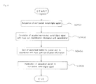
- Fig. 4 is a flowchart of the embodiment.
- the processes in the video signal switching system of this embodiment comprises the following steps.
- the non-packet serial digital signal is acquired (S0401).
- the non-packet serial digital signal acquired in S0401 is packetized after being correlated with the input port identification information of the input port, which has acquired the non-packet serial digital signal, thereby generating a packet (S0402).
- the packet, which has been packetized in S0402 is sorted to the output port in accordance with the input port identification information correlated with the packet (S0403).
- the packet, which has been sorted in S0403 is restored to the non-packet serial digital signal.
- the non-packet serial digital signal is packetized, so that it is possible to carry out the switching by utilizing the existing network components, thereby significantly reducing the costs. Moreover, by packetization, it is possible to implement an efficient switching process.
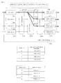
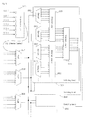
- Fig. 5 is a diagram showing a concrete configuration of a switching unit. Note that, in Fig. 5 , the packetizalion unit 0510 is partially indicated in order to describe the switching unit. At the outset, six SDI signal lines are introduced to the packetization unit 0510, thereby carrying out reization, and respective packets are appropriately outputted to the switching units via one optical cable.
- the destination IP address of each packet is multicast IP address corresponding to a physical position of the input port on the case, and the destination MAC address is multicast MAC address corresponding to the IP address, By this addressing, the input port identification information is correlated with the packet.
- An example of the transmission includes a transmission by means of 10Gbit Ethernet.
- WDM Wavelength Division Multiplexing
- DWDM Densified WDM
- the optical multiplexing it is possible to reduce the number of cables connected to a board for switching process, thereby simplifying the configuration.
- a configuration having eight Multiplexers (Mux) is cited.
- the optical-multiplexed packet is outputted to a switching board for output to each output port.
- the switching unit is configured by eight switching boards.
- the optical-multiplexed packet is outputted to each switching board via a splitter,
- the optical-multiplexed packet is demultiplexed by demultiplexers (Demux) 0541-0544,
- the Ethernet (registered trademark) chips 0551-0553 carry out processing to pass the packet through the output port, or to delete the packet.
- the destination MAC address of the packet is the multicast address corresponding to the destination IP address
- the IP address of the packet is the multicast address corresponding to the physical position of the input port, so that the processing to pass the packet through the output port or to delete the packet by the Ethernet (registered trademark) chips 0551-0553 based on the destination MAC address is equal to the processing based on the IP address.
- the Ethernet (registered trademark) chips 0551-0553 have switching function by utilizing layer-3 IP address, it is possible to directly carry out processing based on the destination IP address. According to this configuration of the input port, it is possible to simplify the physical configuration of the video signal switching system for carrying out switching of a plurality of non-packet signals.
- Fig. 6 is a diagram showing an extended example of the embodiment. Similar to the video signal switching system as shown in Fig. 1 , the video signal switching system 0600 as shown in Fig. 6 comprises a plurality of 'input ports' (0611-0614), a plurality of 'output ports' (0621-0624), a 'packetization unit' (0630), a 'switching unit' (0640), and a 'restoration unit' (0650). In addition, in Fig. 6 , the switching unit 0640 is connected to the external network. In the video signal switching system, the switching process is carried out by utilizing the normal Ethernet (registered trademark) after packetization.
- the normal Ethernet registered trademark
Landscapes
- Engineering & Computer Science (AREA)
- Multimedia (AREA)
- Signal Processing (AREA)
- Business, Economics & Management (AREA)
- Marketing (AREA)
- Data Exchanges In Wide-Area Networks (AREA)
- Studio Circuits (AREA)
- Small-Scale Networks (AREA)
Applications Claiming Priority (1)
| Application Number | Priority Date | Filing Date | Title |
|---|---|---|---|
| PCT/JP2006/309181 WO2007129397A1 (ja) | 2006-05-02 | 2006-05-02 | ビデオ信号スイッチングシステム |
Publications (2)
| Publication Number | Publication Date |
|---|---|
| EP2015569A1 true EP2015569A1 (de) | 2009-01-14 |
| EP2015569A4 EP2015569A4 (de) | 2010-04-07 |
Family
ID=38667515
Family Applications (1)
| Application Number | Title | Priority Date | Filing Date |
|---|---|---|---|
| EP06746031A Withdrawn EP2015569A4 (de) | 2006-05-02 | 2006-05-02 | Videosignalumschaltsystem |
Country Status (5)
| Country | Link |
|---|---|
| US (1) | US20090097496A1 (de) |
| EP (1) | EP2015569A4 (de) |
| JP (1) | JPWO2007129397A1 (de) |
| CA (1) | CA2650869A1 (de) |
| WO (1) | WO2007129397A1 (de) |
Families Citing this family (15)
| Publication number | Priority date | Publication date | Assignee | Title |
|---|---|---|---|---|
| DE102011078021A1 (de) * | 2011-06-22 | 2012-12-27 | Institut für Rundfunktechnik GmbH | Vorrichtung und Verfahren zum Schalten von Echtzeitmedienströmen |
| US9548960B2 (en) * | 2013-10-06 | 2017-01-17 | Mellanox Technologies Ltd. | Simplified packet routing |
| US10069802B2 (en) * | 2014-02-18 | 2018-09-04 | Ciena Corporation | Method for securely configuring customer premise equipment |
| US10038651B2 (en) | 2015-09-05 | 2018-07-31 | Nevion Europe As | Asynchronous switching system and method |
| JP6178370B2 (ja) * | 2015-09-09 | 2017-08-09 | 株式会社メディアリンクス | 映像伝送システム及び映像受信装置 |
| US10819621B2 (en) | 2016-02-23 | 2020-10-27 | Mellanox Technologies Tlv Ltd. | Unicast forwarding of adaptive-routing notifications |
| TWM535913U (zh) * | 2016-09-26 | 2017-01-21 | 宏正自動科技股份有限公司 | 視訊矩陣控制設備 |
| US10644995B2 (en) | 2018-02-14 | 2020-05-05 | Mellanox Technologies Tlv Ltd. | Adaptive routing in a box |
| CN110858925B (zh) * | 2018-08-22 | 2021-10-15 | 华为技术有限公司 | 一种实现视频流切换的方法、设备、系统和存储介质 |
| US11005724B1 (en) | 2019-01-06 | 2021-05-11 | Mellanox Technologies, Ltd. | Network topology having minimal number of long connections among groups of network elements |
| US11063683B1 (en) * | 2020-06-12 | 2021-07-13 | Ciena Corporation | Scalable ROADM architecture with multi-plane switching |
| US11575594B2 (en) | 2020-09-10 | 2023-02-07 | Mellanox Technologies, Ltd. | Deadlock-free rerouting for resolving local link failures using detour paths |
| US11411911B2 (en) | 2020-10-26 | 2022-08-09 | Mellanox Technologies, Ltd. | Routing across multiple subnetworks using address mapping |
| US11870682B2 (en) | 2021-06-22 | 2024-01-09 | Mellanox Technologies, Ltd. | Deadlock-free local rerouting for handling multiple local link failures in hierarchical network topologies |
| US11765103B2 (en) | 2021-12-01 | 2023-09-19 | Mellanox Technologies, Ltd. | Large-scale network with high port utilization |
Citations (4)
| Publication number | Priority date | Publication date | Assignee | Title |
|---|---|---|---|---|
| EP0531599B1 (de) * | 1991-09-13 | 1998-07-22 | International Business Machines Corporation | Konfigurierbare gigabit/s Vermittlunganpassungseinrichtung |
| EP0581486B1 (de) * | 1992-07-24 | 2002-09-25 | AT&T Corp. | Paketschalter mit grosser Bandbreite |
| US6553028B1 (en) * | 1999-04-30 | 2003-04-22 | Cisco Technology, Inc. | Method and apparatus for multicast switching using a centralized switching engine |
| US6553073B1 (en) * | 1996-09-30 | 2003-04-22 | Sony Corporation | Sending device, receiving device, sending-receiving device, transmitter, and transmitting method |
Family Cites Families (5)
| Publication number | Priority date | Publication date | Assignee | Title |
|---|---|---|---|---|
| US7068667B2 (en) * | 2001-04-27 | 2006-06-27 | The Boeing Company | Method and system for path building in a communications network |
| US6690848B2 (en) * | 2001-06-29 | 2004-02-10 | Nortel Networks Limited | Metropolitan photonic switch |
| JP3839303B2 (ja) * | 2001-11-01 | 2006-11-01 | 株式会社テレビ朝日 | 伝送制御装置 |
| GB2400254A (en) * | 2003-03-31 | 2004-10-06 | Sony Uk Ltd | Video processing |
| JP2005033511A (ja) | 2003-07-14 | 2005-02-03 | Nec Engineering Ltd | マトリックススイッチャー |
-
2006
- 2006-05-02 EP EP06746031A patent/EP2015569A4/de not_active Withdrawn
- 2006-05-02 US US12/226,831 patent/US20090097496A1/en not_active Abandoned
- 2006-05-02 WO PCT/JP2006/309181 patent/WO2007129397A1/ja active Application Filing
- 2006-05-02 CA CA002650869A patent/CA2650869A1/en not_active Abandoned
- 2006-05-02 JP JP2008514341A patent/JPWO2007129397A1/ja not_active Withdrawn
Patent Citations (4)
| Publication number | Priority date | Publication date | Assignee | Title |
|---|---|---|---|---|
| EP0531599B1 (de) * | 1991-09-13 | 1998-07-22 | International Business Machines Corporation | Konfigurierbare gigabit/s Vermittlunganpassungseinrichtung |
| EP0581486B1 (de) * | 1992-07-24 | 2002-09-25 | AT&T Corp. | Paketschalter mit grosser Bandbreite |
| US6553073B1 (en) * | 1996-09-30 | 2003-04-22 | Sony Corporation | Sending device, receiving device, sending-receiving device, transmitter, and transmitting method |
| US6553028B1 (en) * | 1999-04-30 | 2003-04-22 | Cisco Technology, Inc. | Method and apparatus for multicast switching using a centralized switching engine |
Non-Patent Citations (1)
| Title |
|---|
| See also references of WO2007129397A1 * |
Also Published As
| Publication number | Publication date |
|---|---|
| EP2015569A4 (de) | 2010-04-07 |
| CA2650869A1 (en) | 2007-11-15 |
| JPWO2007129397A1 (ja) | 2009-09-17 |
| US20090097496A1 (en) | 2009-04-16 |
| WO2007129397A1 (ja) | 2007-11-15 |
Similar Documents
| Publication | Publication Date | Title |
|---|---|---|
| EP2015569A1 (de) | Videosignalumschaltsystem | |
| USRE48325E1 (en) | Embedded audio routing switcher | |
| EP2081124B1 (de) | Endoskopisches chirurgisches System auf Netzwerkbasis | |
| EP2119130B1 (de) | Vorrichtung und verfahren zur softmedienverarbeitung innerhalb eines routing-schalters | |
| US8810668B2 (en) | Camera system, video selection apparatus and video selection method | |
| US10200633B2 (en) | Camera system, video selection apparatus and video selection method | |
| JP2004242320A (ja) | 電気バッファを利用した大容量光ルータ | |
| GB2397462A (en) | Video network with multicast feature | |
| KR100526543B1 (ko) | Vcc정보를 이용한 디지털 방송 채널 스위칭 장치 및 그방법 | |
| WO2021029165A1 (ja) | 信号処理装置および信号処理方法 | |
| WO2007079241A2 (en) | Method and apparatus for enabling transport of ethernet data over a serial digital interface transport service | |
| US6597695B1 (en) | Bit robbing ATM channels | |
| CN201352834Y (zh) | 基于数字电视hdtv平台的高清会议系统 | |
| CA2358607A1 (en) | Packet identifier (pid) aliasing for a broadband audio, video and data router | |
| US20060039375A1 (en) | Method, communication system and communication device for trainsmitting broadcasting information via a communication network | |
| JP7084766B2 (ja) | Ipビデオ割込装置 | |
| US7450608B2 (en) | Subscriber distribution network apparatus and subscriber line unit that facilitates connection to network switch | |
| KR20010109130A (ko) | Atm 전송 시스템용 네트워크 노드 | |
| JP2006217387A (ja) | 放送ネットワークシステム | |
| EP1202499A2 (de) | Lenkung von Packetizierten Beitbanddaten | |
| US20060126626A1 (en) | System and method of sharing video head ends | |
| JPH07203406A (ja) | 多地点間テレビ会議用端末 | |
| JP2001111526A (ja) | 通信方法および通信装置 | |
| JP2003189274A (ja) | テレビ会議システム及び信号伝送装置 | |
| JP2002290833A (ja) | 映像切替ネットワークシステム |
Legal Events
| Date | Code | Title | Description |
|---|---|---|---|
| PUAI | Public reference made under article 153(3) epc to a published international application that has entered the european phase |
Free format text: ORIGINAL CODE: 0009012 |
|
| 17P | Request for examination filed |
Effective date: 20081110 |
|
| AK | Designated contracting states |
Kind code of ref document: A1 Designated state(s): AT BE BG CH CY CZ DE DK EE ES FI FR GB GR HU IE IS IT LI LT LU LV MC NL PL PT RO SE SI SK TR |
|
| AX | Request for extension of the european patent |
Extension state: AL BA HR MK YU |
|
| A4 | Supplementary search report drawn up and despatched |
Effective date: 20100310 |
|
| 17Q | First examination report despatched |
Effective date: 20100616 |
|
| STAA | Information on the status of an ep patent application or granted ep patent |
Free format text: STATUS: THE APPLICATION HAS BEEN WITHDRAWN |
|
| 18W | Application withdrawn |
Effective date: 20101028 |