EP2015464A1 - Method and apparatus for transmitting and detecting a spread spectrum chirp signal - Google Patents
Method and apparatus for transmitting and detecting a spread spectrum chirp signal Download PDFInfo
- Publication number
- EP2015464A1 EP2015464A1 EP08252099A EP08252099A EP2015464A1 EP 2015464 A1 EP2015464 A1 EP 2015464A1 EP 08252099 A EP08252099 A EP 08252099A EP 08252099 A EP08252099 A EP 08252099A EP 2015464 A1 EP2015464 A1 EP 2015464A1
- Authority
- EP
- European Patent Office
- Prior art keywords
- signal
- synchronization signal
- chirp
- receiver
- transmitter
- Prior art date
- Legal status (The legal status is an assumption and is not a legal conclusion. Google has not performed a legal analysis and makes no representation as to the accuracy of the status listed.)
- Withdrawn
Links
Images

Classifications
-
- H—ELECTRICITY
- H04—ELECTRIC COMMUNICATION TECHNIQUE
- H04B—TRANSMISSION
- H04B1/00—Details of transmission systems, not covered by a single one of groups H04B3/00 - H04B13/00; Details of transmission systems not characterised by the medium used for transmission
- H04B1/69—Spread spectrum techniques
- H04B1/7163—Spread spectrum techniques using impulse radio
- H04B1/7183—Synchronisation
-
- H—ELECTRICITY
- H04—ELECTRIC COMMUNICATION TECHNIQUE
- H04B—TRANSMISSION
- H04B1/00—Details of transmission systems, not covered by a single one of groups H04B3/00 - H04B13/00; Details of transmission systems not characterised by the medium used for transmission
- H04B1/69—Spread spectrum techniques
- H04B2001/6912—Spread spectrum techniques using chirp
Definitions
- This patent document pertains generally to data communications, and more particularly, but not by way of limitation, to a system and method for transmitting and detecting wideband signals in the presence of noise.
- Coherent detection is better than noncoherent detection for detecting extremely weak spread spectrum signals. That is especially so as signal to noise ratios fall below unity (0dB).
- the coherency bandwidth of the system may, however, be too low to coherently detect the spread spectrum signal over the symbol period duration.
- the receiver must therefore employ noncoherent (i.e., energy accumulation) detection after the coherency bandwidth is reached and exceeded. What is needed is a system and method for coherently detecting extremely weak wideband or spread spectrum signals.
- coherent detection is better than noncoherent detection for detecting extremely weak spread spectrum signals. That is especially so as signal to noise ratios fall below unity (0dB).
- the coherency bandwidth of the system may, however, be too low to coherently detect the spread spectrum signal over the symbol period duration.
- the receiver must therefore employ noncoherent (i.e., energy accumulation) detection after the coherency bandwidth is reached and exceeded.
- system 100 includes a transmitter 102 and a receiver 120.
- Transmitter 102 includes a data source 104, a synchronization signal generator 106, a combiner 108 and a transmit circuit 110.
- Data source 104 generates a stream of data.
- synchronization signal generator 106 generates a chirp signal that is combined with the stream of data using combiner 108 in a manner known in the art
- a frequency domain representation of a chirp signal transmitted by transmitter 102 is shown as transmit signal 140 in Fig. 2 .
- the chirp signal used in transmitter 102 is a complex sinusoid that rapidly sweeps across the frequency bandwidth of the signal.
- each frequency is occupied for only a single chirp sample.
- the received signal 150 may be shifted in frequency due to the offset between the transmitter 102's local oscillator and the local oscillator in receiver 120, as well as any Doppler effects.
- the correlation of received signal 150 with the transmitted chirp is illustrated in Fig. 2 . Despite the presence of a large frequency offset, the received signal is perfectly correlated to the transmitted signal. Note that the received signal's higher frequency components will alias and correlate with the transmitted signal.
- System 100 exploits this property of frequency offset tolerance in order to detect extremely weak signals at significant frequency offsets with respect to the receiver. This is accomplished at the transmitter by simply repeating the chirp sequence a number of times to construct a data un-modulated synchronization sequence.
- receiver 120 includes a receiver circuit 122, a digital correlator 124, a synchronization signal generator 126, a complex conjugate calculator 128 and a demodulator 130.
- Complex conjugate calculator 128 calculates the complex conjugate of a synchronization signal generated by synchronization signal generator 126.
- Digital correlator 124 takes the complex conjugate of the synchronization signal generated by synchronization signal generator 126 and uses it to detect the transmitted synchronization signal. This transmission can be initial signaling for packet-based data transmissions or for access channels.
- synchronization signal generator 126 generates a chirp signal similar to one generated by synchronization signal generator 106.
- System 100 therefore achieves coherent detection of a signal beyond the system's coherency bandwidth through the use of chirp modulation for a data-unmodulated sync or preamble.
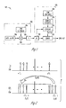
- the sync or preamble is formed by modulating a PN sequence (generated by PN sequence generator 130) with a linear frequency chirp sequence. As shown in Fig. 3 , a length M PN sequence is multiplied by a length N chirp sequence to produce a length M*N concatenated code. This code can be used as a preamble for initial acquisition.
- Fig. 3 reduces processing complexity but at the expense of diminished autocorrelation properties.
- the PN sequence length is chosen to be shorter than the coherency time constant for the system.
- multiple chirp sequences may be concatenated to further reduce the processing complexity. Due to the greatly reduced processing complexity, the receiver can be implemented in off-the-shelf FPGAs or ASICs.
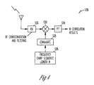
- receiver circuit 122 performs RF down-conversion and filtering while digital correlator 124 is implemented using a Fast Fourier Transform (FFT).
- FFT Fast Fourier Transform
- system 100 solves the problem of detecting a signal with an extremely low signal to noise ratio. It relaxes the coherency bandwidth requirements for a communication system, allowing low cost, lower stability oscillators to be used.
Landscapes
- Engineering & Computer Science (AREA)
- Computer Networks & Wireless Communication (AREA)
- Signal Processing (AREA)
- Synchronisation In Digital Transmission Systems (AREA)
Abstract
Description
- This patent document pertains generally to data communications, and more particularly, but not by way of limitation, to a system and method for transmitting and detecting wideband signals in the presence of noise.
- Coherent detection is better than noncoherent detection for detecting extremely weak spread spectrum signals. That is especially so as signal to noise ratios fall below unity (0dB). For communication systems employing high spreading factors, the coherency bandwidth of the system may, however, be too low to coherently detect the spread spectrum signal over the symbol period duration. The receiver must therefore employ noncoherent (i.e., energy accumulation) detection after the coherency bandwidth is reached and exceeded. What is needed is a system and method for coherently detecting extremely weak wideband or spread spectrum signals.
- In the drawings, which are not necessarily drawn to scale, like numerals describe substantially similar components throughout the several views. Like numerals having different letter suffixes represent different instances of substantially similar components. The drawings illustrate generally, by way of example, but not by way of limitation, various embodiments discussed in the present document.
-
Fig. 1 illustrates a communication system according to the present invention; -
Fig. 2 is a frequency domain representation of the transmitted and received synchronization signals; -
Fig. 3 illustrates a synchronization signal formed by modulating a PN sequence with a chirp sequence; and -
Fig. 4 illustrates one example approach to performing chirp correlation. - In the following detailed description of the preferred embodiments, reference is made to the accompanying drawings which form a part hereof, and in which is shown by way of illustration specific embodiments in which the invention may be practiced. It is to be understood that other embodiments may be utilized and structural changes may be made without departing from the scope of the present invention.
- As noted above, coherent detection is better than noncoherent detection for detecting extremely weak spread spectrum signals. That is especially so as signal to noise ratios fall below unity (0dB). For communication systems employing high spreading factors, the coherency bandwidth of the system may, however, be too low to coherently detect the spread spectrum signal over the symbol period duration. The receiver must therefore employ noncoherent (i.e., energy accumulation) detection after the coherency bandwidth is reached and exceeded.
- A system and method for coherently detecting extremely weak spread spectrum and other wideband signals is shown in
Fig. 1 . InFig. 1 ,system 100 includes atransmitter 102 and areceiver 120.Transmitter 102 includes adata source 104, asynchronization signal generator 106, acombiner 108 and atransmit circuit 110.Data source 104 generates a stream of data. In one embodiment,synchronization signal generator 106 generates a chirp signal that is combined with the stream of data using combiner 108 in a manner known in the art - A frequency domain representation of a chirp signal transmitted by
transmitter 102 is shown as transmit signal 140 inFig. 2 . In one embodiment, the chirp signal used intransmitter 102 is a complex sinusoid that rapidly sweeps across the frequency bandwidth of the signal. In one such embodiment, each frequency is occupied for only a single chirp sample. - At
receiver 120, the receivedsignal 150 may be shifted in frequency due to the offset between thetransmitter 102's local oscillator and the local oscillator inreceiver 120, as well as any Doppler effects. The correlation of receivedsignal 150 with the transmitted chirp is illustrated inFig. 2 . Despite the presence of a large frequency offset, the received signal is perfectly correlated to the transmitted signal. Note that the received signal's higher frequency components will alias and correlate with the transmitted signal. -
System 100 exploits this property of frequency offset tolerance in order to detect extremely weak signals at significant frequency offsets with respect to the receiver. This is accomplished at the transmitter by simply repeating the chirp sequence a number of times to construct a data un-modulated synchronization sequence. - Returning to
Fig. 1 ,receiver 120 includes areceiver circuit 122, adigital correlator 124, asynchronization signal generator 126, acomplex conjugate calculator 128 and ademodulator 130.Complex conjugate calculator 128 calculates the complex conjugate of a synchronization signal generated bysynchronization signal generator 126.Digital correlator 124 takes the complex conjugate of the synchronization signal generated bysynchronization signal generator 126 and uses it to detect the transmitted synchronization signal. This transmission can be initial signaling for packet-based data transmissions or for access channels. In one embodiment,synchronization signal generator 126 generates a chirp signal similar to one generated bysynchronization signal generator 106. -
System 100 therefore achieves coherent detection of a signal beyond the system's coherency bandwidth through the use of chirp modulation for a data-unmodulated sync or preamble. - In one embodiment, such as is shown in
Fig. 3 , the sync or preamble is formed by modulating a PN sequence (generated by PN sequence generator 130) with a linear frequency chirp sequence. As shown inFig. 3 , a length M PN sequence is multiplied by a length N chirp sequence to produce a length M*N concatenated code. This code can be used as a preamble for initial acquisition. - An embodiment such as is shown in
Fig. 3 reduces processing complexity but at the expense of diminished autocorrelation properties. In one such embodiment, the PN sequence length is chosen to be shorter than the coherency time constant for the system. In addition, multiple chirp sequences may be concatenated to further reduce the processing complexity. Due to the greatly reduced processing complexity, the receiver can be implemented in off-the-shelf FPGAs or ASICs. - In one embodiment, as illustrated in
Fig. 4 ,receiver circuit 122 performs RF down-conversion and filtering whiledigital correlator 124 is implemented using a Fast Fourier Transform (FFT). The difference in the implementation shown inFig. 4 is that instead of directly correlating with the detection signal, the N received samples are multiplied one-for-one with the detection signal and fed into an N-point FFT. This is functionally equivalent to performing N correlations with the detection signal. - In summary,
system 100 solves the problem of detecting a signal with an extremely low signal to noise ratio. It relaxes the coherency bandwidth requirements for a communication system, allowing low cost, lower stability oscillators to be used. - It is to be understood that the above description is intended to be illustrative, and not restrictive. For example, the above-described embodiments (and/or aspects thereof) may be used in combination with each other. Many other embodiments will be apparent to those of skill in the art upon reviewing the above description. The scope of the invention should, therefore, be determined with reference to the appended claims, along with the full scope of equivalents to which such claims are entitled. In the appended claims, the terms "including" and "in which" are used as the plain-English equivalents of the respective terms "comprising" and "wherein." Also, in the following claims, the terms "including" and "comprising" are openended, that is, a system, device, article, or process that includes elements in addition to those listed after such a term in a claim are still deemed to fall within the scope of that claim. Moreover, in the following claims, the terms "first," "second," and "third," etc. are used merely as labels, and are not intended to impose numerical requirements on their objects.
- The Abstract is provided to comply with 37 C.F.R. §1.72(b), which requires that it allow the reader to quickly ascertain the nature of the technical disclosure. It is submitted with the understanding that it will not be used to interpret or limit the scope or meaning of the claims. Also, in the above Detailed Description, various features may be grouped together to streamline the disclosure. This should not be interpreted as intending that an unclaimed disclosed feature is essential to any claim. Rather, inventive subject matter may lie in less than all features of a particular disclosed embodiment.
Claims (27)
- A method of detecting wideband signals of bandwidth X within a communications system having a coherency time constant of T, comprising:generating a synchronization signal, wherein generating a synchronization signal includes generating a chirp signal that sweeps a portion of bandwidth X;transmitting the synchronization signal;receiving a wideband signal at a receiver; anddetecting the synchronization signal within the wideband signal received at the receiver, wherein detecting includes:generating a detection signal, wherein the detection signal is a complex conjugate of the synchronization signal;correlating the received wideband signal with the detection signal to obtain one or more correlation results; andindicating when the synchronization signal is detected within the wideband signal.
- The method of claim 1, wherein the chirp signal sweeps linearly across the portion of bandwidth X such that each frequency is occupied for only a single chirp sample during each sweep.
- The method of claim 1 or 2, wherein generating a synchronization signal further includes modulating a pseudo-noise, PN, sequence with the chirp signal.
- The method of claim 3, wherein the PN sequence has a length M, wherein M is less than T.
- The method of claim 1, 2, 3 or 4, wherein the chirp signal sweeps linearly across the portion of bandwidth X such that each frequency is occupied for only a single chirp sample during each sweep.
- The method of any preceding claim, wherein the detection signal is of length N and wherein correlating the received wideband signal with the detection signal comprises:multiplying the receive samples with the detection signal to create N product samples; andperforming a transform on the N product samples to obtain a set of correlation results.
- The method of claim 6, wherein the transform is a Fast Fourier Transform.
- The method of any preceding claim, wherein the synchronization signal is detected when the correlation results have a magnitude above a predetermined threshold.
- A transmitter, comprising:a synchronization signal generator, wherein synchronization signal generator generates a synchronization signal, wherein the synchronization signal includes a chirp signal;a data source;
one or more modulators, wherein the modulators modulate data from the data source to form a data-modulated wideband signal of bandwidth X and wherein the modulators modulate the synchronization signal to form a modulated synchronization signal that sweeps a portion of bandwidth X; anda transmitter circuit connected to the one or more modulators, wherein the transmitter circuit transmits the modulated synchronization signal and the data-modulated wideband signal at different times. - The transmitter of claim 9, wherein the chirp signal is a linear frequency chirp signal.
- The transmitter of claim 9, wherein the chirp signal sweeps linearly across the portion of bandwidth X such that each frequency is occupied for only a single chirp sample during each sweep.
- The transmitter of claim 9, wherein the transmitter transmits the modulated synchronization signal as a preamble to the data-modulated wideband signal.
- The transmitter of claim 9, wherein the synchronization signal generator further includes a pseudo-noise generator, wherein the pseudo-noise generator generates a PN sequence of length M, wherein the PN sequence is modulated by the chirp signal to form the synchronization signal.
- The transmitter of claim 13, wherein the transmitter is designed to operate in a system having a coherency time constant of T and wherein M is chosen to be less than T.
- The transmitter of claim 13, wherein the chirp signal is a linear frequency chirp signal.
- The transmitter of claim 13, wherein the chirp signal sweeps linearly across the portion of bandwidth X such that each frequency is occupied for only a single chirp sample during each sweep.
- A receiver for use in a communications system having a coherency time constant of T and a transmitter that transmits wideband signal including a synchronization signal, wherein the synchronization signal includes a chirp signal, the receiver comprising:a receiver circuit for receiving a wideband signal of bandwidth X;a synchronization signal detector, connected to the receiver circuit, wherein the synchronization signal detector detects the synchronization signal within the wideband signal, wherein the synchronization signal detector includes:a detection signal generator, wherein the detection signal generator generates a detection signal, wherein the detection signal is a complex conjugate of the synchronization signal; anda correlator, wherein the correlator correlates the received wideband signal with the detection signal to obtain one or more correlation results and wherein the correlator indicates when the synchronization signal is detected as a function of the correlation results; anda demodulator connected to the synchronization signal detector, wherein the demodulator recovers data from the wideband signal after the synchronization signal is detected.
- The receiver of claim 17, wherein the chirp signal is a linear frequency chirp signal.
- The receiver of claim 17 or 18, wherein the chirp signal sweeps linearly across the portion of bandwidth X such that each frequency is occupied for only a single chirp sample during each sweep.
- The receiver of claim 17, 18 or 19, wherein the synchronization signal is transmitted as a preamble.
- The receiver of claim 17, 18, 19 or 20, wherein the synchronization signal includes a pseudo-noise, PN, sequence modulated by the chirp signal, wherein the PN sequence is of length M, wherein M is less than a coherency time constant.
- The receiver of claim 21, wherein the chirp signal is a linear frequency chirp signal.
- The receiver of claim 21, wherein the chirp signal sweeps linearly across the portion of bandwidth X such that each frequency is occupied for only a single chirp sample during each sweep.
- The receiver of any of claims 17 to 23, wherein the detection signal is of length N and wherein the correlator includes:a multiplication circuit, wherein the multiplication circuit multiplies the receive samples with the detection signal to create N product samples; andmeans for performing a transform on the N product samples to obtain a set of correlation results.
- The receiver of claim 24, wherein the transform is a Fast Fourier Transform.
- The receiver of claim 17, wherein the synchronization signal is detected when the correlation results have a magnitude above a predetermined threshold.
- A communication system having a coherency time constant T, comprising:one or more transmitters according to any of claims 9 to 16, and one or more receivers according to any one of claims 17 to 26.
Applications Claiming Priority (1)
| Application Number | Priority Date | Filing Date | Title |
|---|---|---|---|
| US11/764,597 US9088349B2 (en) | 2007-06-18 | 2007-06-18 | System and method for transmitting and detecting spread spectrum signals |
Publications (1)
| Publication Number | Publication Date |
|---|---|
| EP2015464A1 true EP2015464A1 (en) | 2009-01-14 |
Family
ID=39764820
Family Applications (1)
| Application Number | Title | Priority Date | Filing Date |
|---|---|---|---|
| EP08252099A Withdrawn EP2015464A1 (en) | 2007-06-18 | 2008-06-18 | Method and apparatus for transmitting and detecting a spread spectrum chirp signal |
Country Status (2)
| Country | Link |
|---|---|
| US (1) | US9088349B2 (en) |
| EP (1) | EP2015464A1 (en) |
Cited By (1)
| Publication number | Priority date | Publication date | Assignee | Title |
|---|---|---|---|---|
| US9083444B2 (en) | 2013-03-12 | 2015-07-14 | Digi International Inc. | Chirp spread spectrum system and method |
Families Citing this family (7)
| Publication number | Priority date | Publication date | Assignee | Title |
|---|---|---|---|---|
| US9088348B2 (en) | 2007-06-18 | 2015-07-21 | Digi International Inc. | System and method for obtaining frequency and time synchronization in a wideband communication system |
| GB2490140B (en) * | 2011-04-19 | 2018-01-31 | Qualcomm Technologies Int Ltd | Chirp communications |
| TWI448094B (en) * | 2012-09-24 | 2014-08-01 | Princeton Technology Corp | System and method of dual chirp modulation |
| US9766321B2 (en) | 2013-03-14 | 2017-09-19 | Digi International Inc. | Indoor positioning with radio frequency chirp signal propagation delay measurement |
| EP3002884B1 (en) * | 2014-09-30 | 2018-04-18 | Semtech Corporation | Wireless communication method |
| US11736142B2 (en) * | 2020-12-31 | 2023-08-22 | Sure-Fi, Inc. | Single chirp data alignment for chirp spread spectrum |
| CN115580512B (en) * | 2022-09-05 | 2023-10-31 | 深圳市国电科技通信有限公司 | Method for transmitting information and low-power consumption wide area communication system |
Citations (3)
| Publication number | Priority date | Publication date | Assignee | Title |
|---|---|---|---|---|
| US6493405B1 (en) * | 1999-03-02 | 2002-12-10 | Harris Corporation | Correlator having enhanced memory for reference and input data |
| US20030022651A1 (en) * | 1999-12-21 | 2003-01-30 | Rudolf Bannasch | Method and devices for transmitting and receiving information |
| EP1599001A1 (en) * | 2003-02-25 | 2005-11-23 | Yokohama TLO Company, Ltd. | Pulse waveform producing method |
Family Cites Families (11)
| Publication number | Priority date | Publication date | Assignee | Title |
|---|---|---|---|---|
| US4532603A (en) * | 1983-03-09 | 1985-07-30 | The United States Of America As Represented By The Secretary Of The Army | Chirp transform correlator |
| US6396866B1 (en) * | 1998-05-01 | 2002-05-28 | Trw Inc. | Symmetric chirp communications acquisition method and apparatus |
| US7245930B1 (en) | 1998-11-24 | 2007-07-17 | Hughes Network Systems, Llc | Acquisition mechanism for a mobile satellite system |
| US7177343B1 (en) * | 2000-05-17 | 2007-02-13 | Zenith Electronics Corporation | Compound chirp and synchronizer for using same |
| US7068704B1 (en) * | 2001-09-26 | 2006-06-27 | Itt Manufacturing Enterpprises, Inc. | Embedded chirp signal for position determination in cellular communication systems |
| JP2005522970A (en) | 2002-04-10 | 2005-07-28 | ナノトロン・テクノロジーズ・ゲゼルシャフト・ミット・ベシュレンクテル・ハフツング | transceiver |
| US6943405B2 (en) | 2003-07-01 | 2005-09-13 | International Business Machines Corporation | Integrated circuit having pairs of parallel complementary FinFETs |
| US7702002B2 (en) * | 2004-01-28 | 2010-04-20 | Qualcomm Incorporated | Rapid acquisition methods and apparatus for GPS signals |
| WO2006058006A2 (en) * | 2004-11-22 | 2006-06-01 | Baker Hughes Incorporated | Identification of the channel frequency response using chirps and stepped frequencies |
| KR100702202B1 (en) * | 2005-02-23 | 2007-04-03 | 오소트론 주식회사 | Method and Apparatus for Channel Estimation to Electro-Magnetic Wave Multi Path between Sender and Receiver by Using Chirp Signal |
| US9088348B2 (en) | 2007-06-18 | 2015-07-21 | Digi International Inc. | System and method for obtaining frequency and time synchronization in a wideband communication system |
-
2007
- 2007-06-18 US US11/764,597 patent/US9088349B2/en active Active
-
2008
- 2008-06-18 EP EP08252099A patent/EP2015464A1/en not_active Withdrawn
Patent Citations (3)
| Publication number | Priority date | Publication date | Assignee | Title |
|---|---|---|---|---|
| US6493405B1 (en) * | 1999-03-02 | 2002-12-10 | Harris Corporation | Correlator having enhanced memory for reference and input data |
| US20030022651A1 (en) * | 1999-12-21 | 2003-01-30 | Rudolf Bannasch | Method and devices for transmitting and receiving information |
| EP1599001A1 (en) * | 2003-02-25 | 2005-11-23 | Yokohama TLO Company, Ltd. | Pulse waveform producing method |
Cited By (3)
| Publication number | Priority date | Publication date | Assignee | Title |
|---|---|---|---|---|
| US9083444B2 (en) | 2013-03-12 | 2015-07-14 | Digi International Inc. | Chirp spread spectrum system and method |
| US9356646B2 (en) | 2013-03-12 | 2016-05-31 | Digi International Inc. | Chirp spread spectrum system and method |
| US9628807B2 (en) | 2013-03-12 | 2017-04-18 | Digi International Inc. | Chirp spread spectrum system and method |
Also Published As
| Publication number | Publication date |
|---|---|
| US9088349B2 (en) | 2015-07-21 |
| US20080310481A1 (en) | 2008-12-18 |
Similar Documents
| Publication | Publication Date | Title |
|---|---|---|
| US9088349B2 (en) | System and method for transmitting and detecting spread spectrum signals | |
| US9088348B2 (en) | System and method for obtaining frequency and time synchronization in a wideband communication system | |
| EP2613174B1 (en) | Radar device | |
| US6498822B1 (en) | Frequency and timing synchronization circuit making use of a chirp signal | |
| CN112327287A (en) | Controlling radar transmissions to achieve interference suppression | |
| US20200256948A1 (en) | Radar-based communication | |
| WO2012037680A1 (en) | Radar system with integrated communication functionality | |
| US20190018127A1 (en) | Radar system | |
| JP2008512960A (en) | OFDM position location signaling using a mutually exclusive subset of subcarriers | |
| US8254437B2 (en) | Transmitting apparatus, receiving apparatus and communication system | |
| KR940012875A (en) | A receiver having a correlation means and receiving a pseudo noise modulated signal and a transmission system comprising the same | |
| EP2063545B1 (en) | Synchronization for FH communication | |
| WO1997045752A1 (en) | Virtual noise radar waveform for reduced radar detectability | |
| US8072383B1 (en) | Navigation and position determination with a multicarrier modulation signal of opportunity | |
| CN113419201A (en) | System and method for wireless communication synchronization for Magnetic Resonance Imaging (MRI) systems | |
| CN105765872A (en) | Spread spectrum signal generating method, generating apparatus, receiving method and receiving apparatus | |
| CN109412644A (en) | A kind of doppler frequency estimation method of direct expansion msk signal | |
| CN1104095C (en) | Code division muliple access transmitter and receiver | |
| JP2013162293A (en) | Wireless communication apparatus, wireless transmitter and wireless receiver | |
| CN109547060B (en) | Frequency hopping spread spectrum signal transmitting device, frequency hopping spread spectrum signal receiving device, frequency hopping spread spectrum communication system and frequency hopping spread spectrum communication method | |
| Gaglione et al. | Fractional fourier transform based co-radar waveform: experimental validation | |
| EP3367579B1 (en) | Orthogonal correlation signals for detection and synchronization at low snr | |
| CN102798871A (en) | Pseudo code capturing method and device based on pseudo code reconstruction | |
| EP1936401A1 (en) | Method and radar system for transmitting information | |
| US6912262B1 (en) | Wideband symbol synchronization in the presence of multiple strong narrowband interference |
Legal Events
| Date | Code | Title | Description |
|---|---|---|---|
| PUAI | Public reference made under article 153(3) epc to a published international application that has entered the european phase |
Free format text: ORIGINAL CODE: 0009012 |
|
| PUAI | Public reference made under article 153(3) epc to a published international application that has entered the european phase |
Free format text: ORIGINAL CODE: 0009012 |
|
| 17P | Request for examination filed |
Effective date: 20080709 |
|
| AK | Designated contracting states |
Kind code of ref document: A1 Designated state(s): AT BE BG CH CY CZ DE DK EE ES FI FR GB GR HR HU IE IS IT LI LT LU LV MC MT NL NO PL PT RO SE SI SK TR |
|
| AX | Request for extension of the european patent |
Extension state: AL BA MK RS |
|
| 17Q | First examination report despatched |
Effective date: 20090615 |
|
| AKX | Designation fees paid |
Designated state(s): DE FR GB |
|
| STAA | Information on the status of an ep patent application or granted ep patent |
Free format text: STATUS: THE APPLICATION IS DEEMED TO BE WITHDRAWN |
|
| 18D | Application deemed to be withdrawn |
Effective date: 20091229 |