EP2013940B1 - A cellular antenna and systems and methods therefor - Google Patents
A cellular antenna and systems and methods therefor Download PDFInfo
- Publication number
- EP2013940B1 EP2013940B1 EP07760274.6A EP07760274A EP2013940B1 EP 2013940 B1 EP2013940 B1 EP 2013940B1 EP 07760274 A EP07760274 A EP 07760274A EP 2013940 B1 EP2013940 B1 EP 2013940B1
- Authority
- EP
- European Patent Office
- Prior art keywords
- antenna
- array
- azimuth
- orientation
- controller
- Prior art date
- Legal status (The legal status is an assumption and is not a legal conclusion. Google has not performed a legal analysis and makes no representation as to the accuracy of the status listed.)
- Not-in-force
Links
Images


Classifications
-
- H—ELECTRICITY
- H01—ELECTRIC ELEMENTS
- H01Q—ANTENNAS, i.e. RADIO AERIALS
- H01Q1/00—Details of, or arrangements associated with, antennas
- H01Q1/12—Supports; Mounting means
- H01Q1/22—Supports; Mounting means by structural association with other equipment or articles
- H01Q1/24—Supports; Mounting means by structural association with other equipment or articles with receiving set
- H01Q1/241—Supports; Mounting means by structural association with other equipment or articles with receiving set used in mobile communications, e.g. GSM
- H01Q1/246—Supports; Mounting means by structural association with other equipment or articles with receiving set used in mobile communications, e.g. GSM specially adapted for base stations
-
- H—ELECTRICITY
- H01—ELECTRIC ELEMENTS
- H01Q—ANTENNAS, i.e. RADIO AERIALS
- H01Q25/00—Antennas or antenna systems providing at least two radiating patterns
-
- H—ELECTRICITY
- H01—ELECTRIC ELEMENTS
- H01Q—ANTENNAS, i.e. RADIO AERIALS
- H01Q3/00—Arrangements for changing or varying the orientation or the shape of the directional pattern of the waves radiated from an antenna or antenna system
- H01Q3/02—Arrangements for changing or varying the orientation or the shape of the directional pattern of the waves radiated from an antenna or antenna system using mechanical movement of antenna or antenna system as a whole
- H01Q3/04—Arrangements for changing or varying the orientation or the shape of the directional pattern of the waves radiated from an antenna or antenna system using mechanical movement of antenna or antenna system as a whole for varying one co-ordinate of the orientation
- H01Q3/06—Arrangements for changing or varying the orientation or the shape of the directional pattern of the waves radiated from an antenna or antenna system using mechanical movement of antenna or antenna system as a whole for varying one co-ordinate of the orientation over a restricted angle
-
- H—ELECTRICITY
- H01—ELECTRIC ELEMENTS
- H01Q—ANTENNAS, i.e. RADIO AERIALS
- H01Q3/00—Arrangements for changing or varying the orientation or the shape of the directional pattern of the waves radiated from an antenna or antenna system
- H01Q3/26—Arrangements for changing or varying the orientation or the shape of the directional pattern of the waves radiated from an antenna or antenna system varying the relative phase or relative amplitude of energisation between two or more active radiating elements; varying the distribution of energy across a radiating aperture
- H01Q3/30—Arrangements for changing or varying the orientation or the shape of the directional pattern of the waves radiated from an antenna or antenna system varying the relative phase or relative amplitude of energisation between two or more active radiating elements; varying the distribution of energy across a radiating aperture varying the relative phase between the radiating elements of an array
- H01Q3/34—Arrangements for changing or varying the orientation or the shape of the directional pattern of the waves radiated from an antenna or antenna system varying the relative phase or relative amplitude of energisation between two or more active radiating elements; varying the distribution of energy across a radiating aperture varying the relative phase between the radiating elements of an array by electrical means
- H01Q3/36—Arrangements for changing or varying the orientation or the shape of the directional pattern of the waves radiated from an antenna or antenna system varying the relative phase or relative amplitude of energisation between two or more active radiating elements; varying the distribution of energy across a radiating aperture varying the relative phase between the radiating elements of an array by electrical means with variable phase-shifters
-
- H—ELECTRICITY
- H01—ELECTRIC ELEMENTS
- H01Q—ANTENNAS, i.e. RADIO AERIALS
- H01Q5/00—Arrangements for simultaneous operation of antennas on two or more different wavebands, e.g. dual-band or multi-band arrangements
- H01Q5/40—Imbricated or interleaved structures; Combined or electromagnetically coupled arrangements, e.g. comprising two or more non-connected fed radiating elements
- H01Q5/42—Imbricated or interleaved structures; Combined or electromagnetically coupled arrangements, e.g. comprising two or more non-connected fed radiating elements using two or more imbricated arrays
Definitions
- This invention relates to a cellular antenna and systems incorporating the antenna as well as to methods of controlling the antenna. More particularly, although not exclusively, there is disclosed an antenna providing mechanical azimuth adjustment of the beam of the antenna in combination with adjustment with other antenna attributes. There is also disclosed a multi-array allowing independent beam steering of each array.
- This invention also relates to a cellular communications antenna including sensors for determining the position and/or orientation of a beam of the antenna. This position and/or orientation information may be utilized locally to control attributes of the antenna or may be communicated to a central controller which may control attributes of the antenna.
- an antenna may be oriented by an actuator
- devices for measuring the movement have been provided but these may not always provide correct information as to the actual orientation of the antenna due to limited calibration at setup or due to non-linearities.
- the orientation of an antenna changes in use (for example due to bird strike) this may not be known by the network operator and network performance may be compromised.
- the present invention provides a cellular antenna according to independent claim 1 and a method of adjusting beam azimuth for a cellular multi-array antenna according to independent claim 6. Further embodiments of the invention are realised according to the corresponding dependent claims.
- An antenna allowing mechanical azimuth adjustment in combination with adjustment of one or more other antenna attribute.
- An integrated control arrangement is provided which can utilize either serial, wireless or RF feed lines to convey communications. Systems incorporating such antennas and methods of controlling them are also provided. The following examples are useful for understanding the invention.
- a cellular antenna comprising:
- a network management system comprising a plurality of base station antenna sites, each with a group of antenna systems as described above.
- a cellular antenna comprising:
- a method of adjusting beam azimuth for a multiband antenna having a first array and a second array in which the first array has a feed network including one or more variable element for adjusting beam azimuth comprising:
- an antenna allowing electrical and/or mechanical beam steering to provide independent steering of the beams of an integrated multi-array antenna.
- An integrated control arrangement is provided which can utilize either serial, wireless or RF feed lines to convey communications.
- Systems incorporating such antennas and methods of controlling them are also provided. A number of embodiments are described and the following embodiments are to be read as non-limiting exemplary embodiments only.
- a cellular antenna comprising:
- a method of azimuth steering the beams of an integrated cellular antenna having a first array of radiating elements arranged in multiple columns and a second array of radiating elements arranged in multiple columns wherein columns of the first array are fed with phase shifted signals such that the azimuth direction of the beam of the first array is oriented in a first direction and wherein columns of the second array are fed with phase shifted signals such that the azimuth direction of the beam of the second array is oriented in a second direction, different to the first direction.
- a cellular antenna comprising;
- a ninth example there is provided a method of setting different beam azimuth orientations for first and second beams of a multi-array antenna having first and second arrays of radiating elements in which the first array has a first feed network including one or more variable elements for adjusting beam azimuth and the second array has a second feed network including one or more variable elements for adjusting beam azimuth, the method comprising:
- a cellular antenna comprising an antenna housing; a plurality of panels of radiating elements relatively rotatable with respect to the antenna housing and azimuth actuators for independently rotating each panel with respect to the antenna housing.
- a method of steering the beam of an antenna comprising a plurality of panels of radiating elements relatively rotatable with respect to an antenna housing having azimuth actuators for independently rotating each panel with respect to the antenna housing, the method comprising rotating selected panels with respect to the antenna housing to achieve a desired beam pattern and or orientation.
- a cellular antenna comprising:
- a cellular communications antenna including sensors for determining position and/or orientation of the antenna. This allows simplified installation and advanced control strategies to be employed. A number of embodiments are described and the following embodiments are to be read as non-limiting exemplary embodiments only.
- a cellular communications antenna comprising:
- a cellular communications antenna comprising:
- a cellular communications antenna system comprising:
- a cellular communications system comprising:
- a method of controlling the orientation of a cellular communications antenna having an orientation sensor for measuring the orientation of the antenna and an actuator for adjusting the orientation of the antenna comprising:
- a method of controlling a beam attribute of a cellular communications antenna having an orientation sensor for measuring the orientation of the antenna and an actuator for adjusting a variable element of an antenna feed network of the antenna comprising:
- a method of determining the configuration of a plurality of antenna systems comprising a plurality of antennas having orientation sensors for measuring the orientation of the antennas and position sensors for determining the positions of the antennas, the method comprising:
- a method of configuring a cellular communications antenna including an orientation sensor for measuring the orientation of the antenna and a position sensor for determining the position of the antenna comprising:
- a method of controlling coverage in a cellular communications system including one or more base station comprising the steps of:
- a method of controlling coverage in a cellular communications system including one or more base station comprising the steps of:
- a cellular communications system comprising:
- a cellular communications system comprising:
- Attributes of an antenna beam may be adjusted by physically orienting an antenna or by adjusting the variable elements in an antenna feed network. Physically adjusting the orientation of an antenna mechanically maintains a better radiation pattern for the antenna beam than hv adjusting a variable element in the feed network. For down tilt a better radiation pattern is obtained by adjusting a variable element in the feed network than by mechanically orienting the antenna.
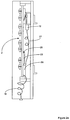
- FIG. 1 shows a side view of a cellular antenna 1 according to a first embodiment.
- Antenna 1 includes an array antenna 2 having a reflector 3 and a plurality of radiating elements 4 (only some of which are indicated and the number of which may vary).
- Reflector 3 is rotatable about bearings 5 and 6 so that the array antenna 2 can rotate with respect to antenna support 7.
- Mounting brackets 8 and 9 allow the antenna to be mounted to a support structure such as a tower.
- An azimuth position actuator 10 rotates array antenna 2 with respect to antenna support 7 in response to drive signals from actuator controller 11.
- Azimuth position actuator 10 may be in the form of a geared azimuth motor 12 driving a threaded shaft 13 which drives a nut 14 up and down as it rotates.
- Nut 14 has a pin 15 projecting therefrom which locates within a helical groove 16 in semi cylindrical guide 17. As pin 15 moves up and down guide 17 causes the array antenna 2 to rotate about its vertical axis to provide mechanical azimuth steering. It will be appreciated that a range of mechanical drive arrangements could be employed, such as geared drive trains, crank arrangements, belt and pulley drives etc.
- an RF feed is supplied to connector 18 and a coiled feed line 19 supplies the RF feed to antenna array 2.
- control signals are provided to serial bus connector 20 and supplied to actuator controller 11 via cable 21.
- Actuator controller 11 controls azimuth motor 12 via cable 22 and controls one or more actuator adjusting one or more variable element contained within variable feed assembly 23 via cable 24.
- Both coiled feed line 19 and cable 24 have excess length to enable ease of rotation of antenna array 2.
- Variable feed assembly 23 may include a single phase shifter or multiple phase shifters to adjust down tilt. Variable feed assembly 23 may additionally or alternatively include one or more phase shifter or power divider to effect beam width adjustment. Variable feed assembly 23 may also include one or more phase shifter to effect electrical azimuth adjustment. Electrical azimuth adjustment may be provided for a multiband antenna so that the azimuth of the antenna beam of a first array may be adjusted mechanically and the antenna beam of a second array may be adjusted electrically to achieve a desired offset.
- Actuator controller 11 may receive status and configuration information from variable feed assembly 23 such as the current position of phase shifters or power dividers or whether an actuator has a fault condition etc.
- a compass 25 may also be provided to give a real-time measurement as to the azimuth orientation of antenna array 2. The basic reading may be adjusted with respect to true North at the place of installation.
- This status and configuration information may be supplied from actuator controller 11 to a base station auxiliary equipment controller via a serial cable connected to serial bus connector 20.
- serial data received by actuator controller 11 will include an address for an actuator controller along with data specifying desired operating parameters.
- actuator controller 11 controls actuators in accordance with control data for an attribute to be controlled.
- actuator controller 11 may receive data for mechanical azimuth with a value of 222 degrees.
- Controller 11 obtains orientation information from compass 25 and drives azimuth motor 12 so as to rotate antenna array 2 until the compass reading from compass 25 corresponds with the desired orientation.
- controller 11 may receive data for a required down tilt angle.
- a down tilt phase shifter actuator such as a geared motor, may drive one or more phase shifter in the feed network until an associated position sensor communicates to actuator controller 11 that the desired phase shifter position has been achieved (see US6198458 , the disclosure of which is incorporated by reference).
- actuator controller 11 may drive one or more phase shifter in the feed network until an associated position sensor communicates to actuator controller 11 that the desired phase shifter position has been achieved (see US6198458 , the disclosure of which is incorporated by reference).
- beam width actuators and azimuth actuators may be driven by actuator controller 11 to achieve desired values.
- actuator controller 11 can control mechanical azimuth and electrical azimuth, down tilt and beam width in response to commands received from a addressable serial bus.
- FIG. 2a shows a second embodiment in which all RF signals and control data are received over a single RF feed line.
- coiled feed line 19 supplies RF feed signals to antenna interface 26 which supplies RF signals to variable feed assembly 23 and extracts and supplies control data to actuator controller 31.
- antenna interface 26 is mounted to reflector 3 a flexible control cable 27 is provided to azimuth motor 12.
- Antenna interface 26 may extract power supplied by an RF feed line to operate actuator controller 23 and it associated actuators.
- a DC bias voltage mav be applied to the RF feed line at the base of a cellular base station tower and extracted by antenna interface 26 at the top of the tower. This arrangement has the advantage that only a single RF feed line need be connected to each antenna to provide both RF signals and control data.
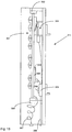
- Figure 2b shows a variant of the embodiment shown in figure 1 where the azimuth position actuator 10a is in the form of a top mounted geared motor which supports antenna array 2 and rotates it.
- the base of the antenna is maintained in position by bearing 6a secured to the base of the antenna and extending to the walls of the radome 7a.
- RF feed line 28 feeds differential phase shifter 29, which in this example is a variable differential phase shifter.
- Actuator 30 is driven by actuator controller 31 to adjust the position of the variable differential phase shifter 29 to achieve a desired beam down tilt.
- Actuators 35 to 37 are driven by actuator controller 31 to adjust power dividers 32 to 34 to adjust antenna beam width.
- FIG. 14 shows an embodiment including a down tilt phase shifter 200 driven by a down tilt phase shifter actuator 201, power dividers 202, 203 and 204 driven by power divider actuator 205 and azimuth phase shifters 206, 207 and 208 driven by azimuth phase shifter actuator 209 to effect down tilt, beam width and azimuth adjustment of the antenna beam. It will be appreciated that any one or combination of attributes may be adjusted depending upon the application. In a simple application electrical down tilt adjustment may be provided with mechanical azimuth adjustment.
- a first array of columns of radiating elements 49 mav have a feed network as shown in figure 3a whilst the second array of columns of radiating elements 48 may have a feed network 48a including phase shifter 48b to vary the phase supplied to the outer columns of radiating elements to effect azimuth beam steering.
- the beam direction for the first array may be set mechanically by mechanically orienting the antenna and the beam direction for the second array may be offset using electrical azimuth adjustment in the feed network.
- the arrays may operate in the same or different frequency bands.
- array 49 operates in a higher band than array 48.
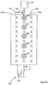
- Figure 3c shows a multi-array antenna having an array of low-frequency band radiating elements which may, for example, take the form of ring radiators 126, 127, 128, 129 and 130 and an array consisting of three columns 131, 132 and 133 of high frequency band radiating elements which may, for example, take the form of cross dipoles 131a, 132a and 133a. It will be appreciated that the radiating elements may be of any suitable form depending upon the application.
- Feed network 134 consists of a through line 135 feeding central column 132 and variable phase shifter 136 feeding columns 131 and 133.
- a mechanical azimuth actuator shown schematically as 137 rotates antenna 125 about its vertical axis to provide mechanical azimuth steering.
- the azimuth direction of the beam of low band elements 126 to 130 may be set by driving mechanical azimuth actuator 137 to orient antenna 125 in the desired orientation.
- Variable differential phase shifter 136 may then be adjusted to orient the azimuth direction of the beam of the high band elements.
- a local controller may control mechanical azimuth actuator 137 and an actuator to control variable differential phase shifter 136. This may be based on a local control arrangement or in response to control commands from a central controller.
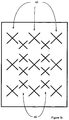
- Figure 3d shows a multi-array antenna 138 consisting of an array of high band elements in the form of three columns of cross dipoles (one of which is indicated at 139) and an array of low band elements in the form of three columns of ring radiators (one of which is indicated at 140) which may be staggered and interleaved as shown.
- one feed network 141 may be provided to feed the columns of the high band radiating elements so that the central column of high band elements is fed by line 142 directly from RF feed line 143 and the outer columns of high band elements are fed by lines 144 and 145 from the outputs of phase shifter 146 which may be any of a variety of electromechanical or electrical configurations.
- the RF feed and control arrangement could be anv of a variety of configurations.
- Mechanical azimuth actuator 147 allows mechanical azimuth beam steering of antenna 138. This embodiment may operate in the same manner as the embodiment described in figure 3c . However, if the low band columns are fed in the same manner as the high band columns (i.e. using a feed network as per feed network 141) then the beams of both the high band and low band arrays may be individually electronically steered. Thus mechanical azimuth actuator 147 may be adjusted to orient antenna 138 in a first orientation and the independent high band and low band feed networks may be used to electronically steer the azimuth beam directions for each array.
- the antenna to be mechanically oriented to position between the desired beam orientation for each array and for the beam of each array to the offset by electronic beam steering to achieve the designed beam orientations. This may minimize distortion of beam patterns by reducing the amount of electrical azimuth beam steering required.
- an infinitude of azimuthal settings of the two beams can be achieved to satisfy traffic and other design parameters.
- the high frequency band radiating elements may be in the range of 1710 to 1720 MHz and the low frequency band radiating elements may be in the range of 824 to 960 MHz.
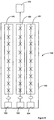
- Figure 3e shows a variant of figure 3d in which feed network 141 is replaced by feed network 141 a in which active elements are employed to achieve the desired phase shift for the radiating elements of each column.
- the active elements may be PIN diodes, optically controlled elements or any other suitable active element.
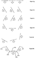
- Figure 3f shows an antenna 148 having panels of radiating elements rotatable via actuators 152 to 154 with respect to antenna housing 155.
- the arrays may be single as shown schematically, or multiple column arrays. This arrangement enables each array of each panel 149 to 151 to be independently oriented with respect to antenna housing 155. Further, antenna housing 155 may itself be rotationally oriented via actuator 156.
- Figures 3g to 3l illustrate possible configurations of antenna 148. In figure 3g all panels are oriented flat with respect to antenna housing 155. In figure 3h all panels are rotated by the same amount to the left and in figure 3j all panels are rotated by the same amount to the right. In figure 3k the outer panels 149 and 151 are rotated outwardly to broaden the beam of the antenna. In figure 3l the configuration of figure 3k is rotated due to actuator 156 rotating antenna housing 155. Thus the antenna provides azimuth steering and beam shaping by rotation of multiple antenna radiator panels.
- Figure 3m shows a variant in which outer panels 210 and 211 of radiating elements are pivotable about joints 213 and 214 to central panel of radiating elements 212.
- Outer panels 210 and 211 may be independently rotated with respect to central panel 212 by individual mechanical actuators or both may be adjusted via a common mechanical linkage 215. This arrangement allows a wide beam width to be generated using a relatively simple antenna structure.
- each antenna may provide information as to the configuration and orientation of each antenna and control the antenna locally according to a local control strategy or centrally based on a global control strategy.
- Auxiliary equipment controller 51 includes a connector 52 allowing a laptop 53 to interface with base station auxiliary equipment controller 51.
- FIG. 5 shows a first embodiment in which a base station controller 55 communicates with a central controller via a backhaul link 54.
- Commands for controlling antenna attributes are sent from base station controller 55 to auxiliary equipment controller 51.
- a modulation/demodulation arrangement conveys commands between control interface 50 and antenna interfaces 59 to 61.
- Base station controller 55 sends RF signals for transmission via RF feed lines 57 to control interface 50.
- Auxiliary equipment controller 51 sends commands for controlling controllable antenna elements to control interface 50 which superposes control commands onto RF feed lines 56 to 58.
- Each antenna includes an antenna interface 59 to 61 which extracts the superposed control commands and provides these to controller actuators 62 to 64 which control actuators 65 to 67 of antennas 68 to 70.
- any number of actuators may be controlled and that these may include control motors to adjust the physical position of an antenna, actuators to adjust phase shifters, actuators to adjust power dividers or other adjustable elements.
- the control data will include an address for an actuator controller along with control data designating the attribute to be controlled (e.g. down tilt) and a desired value.
- the actuator controllers may also send status and configuration information to antenna interface is 59 to 61 to be conveyed via control interface 50 to auxiliary equipment controller 51. This status and configuration information may be supplied to a central controller via backhaul link 54.
- Figure 6 shows a modified version in which like integers and have been given like numbers.
- the control interface 71 superposes the control data only on RF line 58.
- An antenna interface 72 is incorporated within antenna 68 and this provides the control data to actuator controllers 62 to 64 via serial cables 73 to 75. This arrangement reduces cost by only requiring a single antenna interface 72 and for control interface 71 to interface only with one feed cable.
- Figure 7 shows an embodiment similar to figure 6 except that the antenna interface 77 is located externally to antennas 68 to 70 at the top of a tower.
- Actuator controllers 62 to 64 are supplied with control data via serial bus connections 78 to 80.
- This arrangement has the advantage that a standardised antenna unit 68 to 70 may be employed whether control data either is sent up the tower via an RF feed line or a serial cable.
- Figure 8 shows an embodiment in which control data is sent up tower 81 from auxiliary equipment controller 82 via serial cable 83 to antennas 84 to 86.
- An access port 87 is provided to enable a portable controller (e.g. a laptop) 88 to communicate directly with auxiliary equipment controller 82 to effect local control.
- actuator controllers 89 to 91 and auxiliary equipment controller 82 are interconnected by serial buses 83, 92 and 93.
- Actuators 194 to 196 are controlled by actuator controllers 89 to 91 in accordance with control data received from auxiliary equipment controller 82.
- Status and configuration information from actuator controllers 89 to 91 is communicated via the serial bus to auxiliary equipment controller 82.
- FIG 10 shows a wireless embodiment in which control data is communicated between a controller 94 and antennas 95 to 97 directly via a wireless link.
- controller 94 may be an auxiliary equipment controller at the base station supporting wireless communication or a portable device such as a laptop with a wireless card etc.
- Controller 94 may also be remotely located and control antennas 95 to 97 via a long-range radio link.
- Figure 11 shows a first embodiment in which a single antenna interface 98 communicates wirelessly with a controller 94 and communicates with actuator controllers 99 to 101 via serial bus 102 to 104 to control actuators 108 to 110.
- This arrangement allows standard antennas 105 to 107 having serial interfaces to be employed.
- Figure 12 shows an embodiment in which actuator controllers 111 to 113 include wireless communication circuits enabling each actuator controller 111 to 113 to communicate directly with a controller 94.
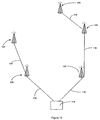
- FIG 13 shows schematically a network management system in which a central controller 114 communicates via backhaul links 115 to 119 with a number of base stations 120 to 124.
- Central controller 114 obtains status and configuration information from each base station controller and sends control data to base stations 120 to 124.
- Central controller 114 may periodically receive status and configuration information and/or status and configuration information may be sent on request or whenever there is a change.
- Central controller 114 may adjust antenna attributes according to a schedule, on operator command or actively in response to current operating conditions (e.g. traffic demands etc).
- Figure 15 shows an antenna 311.
- Figure 16 shows schematically the control arrangement for the antenna.
- An array antenna 301 is rotatable about bearings 302 and 303 with rotation of the array antenna being controlled by actuator 304.
- Control data is sent to antenna controller 305 via an addressable serial bus 306, for example..
- control data may be supplied via RF feed line 307 or a wireless link.
- a global positioning satellite (GPS) receiver 308, for example, supplies position information to antenna controller 305.
- Antenna controller 305 controls actuators 312 to 313 within feed network 309 to control antenna beam orientation with respect to the array antenna.
- GPS global positioning satellite
- the actuators 312 to 313 of feed network 309 may adjust phase shifters and or power dividers to adjust the azimuth, downtilt and/or beam width of the antenna beam with respect to the plane of the array antenna as described in Elliot and Rhodes.
- an orientation sensor 310 is permanently mounted to the array antenna 301 and develops a signal characterizing the orientation of the antenna.
- the orientation sensor may include an electronic compass and/or gyroscope to determine beam azimuth and/or an inclinometer and/or gyroscope to measure beam elevation.
- a relative position determining method may be employed, such as determining relative orientation with respect to another base station (or beacon etc.) by determining the direction in which a narrow beam (RF, laser etc) must be directed to be received by the base station or beacon. Knowing the positions of the base stations relative orientations of the antennas can be determined.
- the sensor signal from orientation sensor 310 is supplied to antenna controller 305.
- antenna controller 305 of cellular communications antenna 311 may store desired physical orientation or antenna beam orientation information therein.
- antenna controller may control actuator 304 to achieve a desired azimuth orientation of array antenna 301 or may control actuators of feed network 309 to adjust downtilt and/or azimuth and/or beam width of the beam of the antenna with respect to array antenna 301.
- a digital compass of orientation sensor 310 may detect the actual orientation of array antenna 301 and communicate this to antenna controller 305.
- Antenna controller 305 may determine whether the orientation of array antenna 301 is within a permitted range of values stored within antenna controller 305. If it is outside a permitted range antenna controller 305 may adjust actuator 304 to change the physical orientation of array antenna 301 until the sensor signal from orientation sensor 310 indicates an orientation within the permitted range.
- Permitted values of antenna attributes may be stored within antenna controller 305 and may be updated via addressable serial bus 306 or another communications channel.
- the permitted ranges of physical orientation and beam orientation attributes may be stored in a schedule in which these values are set for different periods of time, or for variable traffic, variable foliage or other seasonal changes in capacity or signal obstruction, or other operating conditions. For example, coverage may be required from an antenna in the first region for one period of time and another region for another period of time due to varying traffic demand etc. This schedule can be periodically uploaded from a central controller.
- FIG 17 a schematic view of cellular communications antenna system 314 incorporating the cellular communications antenna shown in figures 15 and 16 is shown.
- Antenna 318 receives GPS positioning signals from GPS satellites 315, 316 and 317. Using this information the controller of antenna 318 can determine its position.
- the antenna beam 319 has adjustable beam attributes including beam width 320, beam elevation (referred to herein as beam down tilt) 321 and horizontal beam orientation (referred to herein as beam azimuth) 322. These attributes of the antenna beam may be adjusted so as to provide the desired beam coverage.
- Figure 18 shows a schematic view of an arrangement for adjusting the physical orientation of antenna 323.
- Actuators 324, 325 and 326 may respectively adjust beam azimuth 327, roll 328 and down tilt 329.
- Actuators 324 to 326 may be geared motors which through suitable linkages adjust the orientation of antenna 323 as is well known in the art.
- FIG 19 there is shown the beam 330 of antenna 331 projected onto a landscape. It will be appreciated that by adjusting attributes of physical orientation and/or adjusting attributes of the beam of the antenna, beam width, beam azimuth, beam downtilt, and beam roll may be optimised for desired coverage based upon the measured position and orientation of antenna 331.
- An image like that shown in figure 19 may be displayed to a user using 2D or 3D display technology.
- the topography represents the environment in which antenna 331 is located. Obstructions, such as buildings, may also be shown. Current, desired or historical traffic levels may also be indicated (by colour, texture or other visual attributes).
- Antenna 331 may be superimposed based on information received as to its physical location derived from a GPS unit at the base station.
- the orientation of antenna 331 may be based upon orientation information from sensors in antenna 331.
- the shape of beam 330 may be determined based on information as to the configuration of beam shaping elements. It may have a different optical characteristic such as colour or shading depending upon the polarisation of the beam.
- a user using a virtual reality data glove or other input device may modify beam 330. By grasping the beam with the data glove a user may orient it as desired or by opening and closing fingers, for example, vary beam width. A user is able to observe how modification of the beam affects the virtual beam in the virtual display, and thus how the real beam would project on the topology. This provides a simple intuitive user interface.
- Figure 20 shows a cellular communication system in which a central controller 332 communicates via backhaul links 333 to 335 with base station controllers 336 to 339.
- Base station controllers 336 to 339 receive position and/or orientation information from antennas 340 to 343 and provide this information to central controller 332.
- base station controllers 336 to 339 may include a GPS receiver, avoiding the need to provide one in each antenna.
- Central controller 332 may maintain a database in which the most current position and orientation data is stored, along with historical data if required. Position and orientation information may be sent periodically to central controller 332 or upon request from central controller 332.
- Central controller 332 may send control commands via base station controllers 336, 337, 338 and 339 to each controller within each antenna to adjust the physical orientation of the antenna and/or antenna beam attributes based upon immediate need, response to predetermined condition changes, or in accordance with a predetermined time schedule, as described above.
- Central controller 332 may determine the desired operating parameters for the antenna and send these back to be stored in the base station controller or the controller within each antenna. Each antenna may then control antenna physical orientation and/or beam orientation to satisfy the required operating parameters. Alternatively, the intelligence may be maintained within central controller 332 so that it directly commands each local antenna controller to make an adjustment until it receives position and/or orientation information meeting the required operating parameters.
- controller 332 may send a schedule of desired operating parameters to the base station controller or antenna controller providing a schedule of operation for different periods. The schedule may provide for different beam coverage for different periods. Further, central controller 332 may monitor system usage and adjust the mechanical orientation and/or beam attributes to provide desired coverage actively as usage changes.
- central controller 332 can monitor correct operation of an entire cellular communications network. If, for example, an antenna should encounter bird strike and become. misaligned, central controller 332 can detect the incorrect orientation of the antenna and, if possible, make adjustment or otherwise properly ensure maintenance is performed.
- Each antenna controller may be programmed so that if a position or orientation parameter is outside a specified range a signal is sent to central controller 332 notifying it of the exception. Controller 332 can then adjust antenna parameters to compensate or indicate that servicing is required.
- graphical user interface described in relation to figure 19 may be applied to a system as shown in figure 19 to enable an operator to control all antenna beams across a system via a user interface at central controller 332.
- the system enables the position and orientation of each antenna to be communicated to the central controller 332 upon installation.
- the settings of beam shaping elements such as phase shifters and power dividers may also be provided to central controller 332 to enable the shape of the beam of each antenna to be determined.
- Controller 332 may also be provided with information as to fixed obstructions (buildings etc.) and variable obstructions (e.g. foliage).
- Controller 332 may further be provided with information as to projected traffic (e.g. typical traffic profiles for different times of the day or for events such as sports events) as well as real-time information as to traffic (e.g. actual current traffic or traffic over a proceeding period). Controller 332 may then calculate the desired physical antenna position and beam configuration for each antenna required to give the desired coverage in a particular typography.
- Controller 332 may do this by overlaying antenna position and orientation information onto a topographical map of the area to calculate desired coverage. Controller 332 may take into account information as to usage and system coverage requirements for the area concerned. Controller 332 may operate a wide range of control strategies utilizing the known antenna position and orientation information as will be apparent to those skilled in the art.
- an operator may control antenna beam orientation and shape using a user interface.
- An operator may see the topology off or portion of an area to be controlled with base stations superimposed upon the topology.
- Beams of the antennas may be projected onto the topology based upon information as to each antenna's position and orientation and the settings of the beam shaping elements of each antenna.
- the pars duration of each beam may be indicated by colour or some other optical attribute. Buildings and other obstructions mav also be shown using visual attributes, such as colour.
- System traffic may be superimposed upon the topography to show current traffic, historical traffic and/or predicted traffic using colour or some other visual attribute. Where multiple attributes need to be shown in the same space one attribute may be colour and another may be a fill effect such as crosshatching etc.
- a user may select a beam using an input device (e.g. amounts, virtual reality data glove etc.) and modify attributes of the antenna beam using the input device.
- an input device e.g. amounts, virtual reality data glove etc.
- modify attributes of the antenna beam using the input device For example an operator may grasp a beam using a virtual reality data glove and change its orientation by moving the data glove. The operator may adjust beam attributes such as being width by opening and closing fingers off the data glove. In this way an operator may adjust a beam while visually observing other beams and the coverage of the beam with respect to traffic in a region and how obstructions affect the beam. It will be appreciated at a variety of input devices could be employed utilizing a range of control strategies.
- Each antenna controller may include an RF receiver for receiving transmissions from known locations, such as cellular towers, to calculate the position of each antenna by triangulation.
- an antenna providing azimuth and down tilt adjustment which maintains good radiation patterns of the antenna.
- a common controller enables mechanical azimuth, electrical down tilt, electrical beam width and electrical azimuth actuators to be commonly controlled.
- An addressable serial bus interface simplifies interconnection of antennas and controllers. Control data may be sent via an RF feed line, serial data cable or wireless connection. For multiband applications the combination of mechanical and electrical azimuth adjustment allows azimuth to be independently adjusted for two or more arrays.
- an antenna providing dual electrical azimuth beam steering, combined mechanical and electrical azimuth steering, independent mechanical column steering and dual mechanical steering. This allows beam azimuth to be independently adjusted for two or more arrays.
- a common controller enables mechanical azimuth, electrical down tilt, electrical beam width and electrical azimuth actuators to be commonly controlled.
- An addressable serial bus interface simplifies interconnection of antennas and controllers. Control data may be sent via an RF feed line, serial data cable or wireless connection.
- an antenna capable of detecting its position and orientation and communicating this to a local or central controller.
- the antenna may include means to maintain attributes of the antenna within desired parameters. These may be preset or downloaded.
- a system of such antennas simplifies installation by only requiring antennas to be mounted in approximate orientations as they may subsequently be adjusted by altering the mechanical orientation of the antenna and/or attributes of the antenna beam. The system enables the precise position and orientation of antennas to be determined at any point in time and employed in a range of control strategies.
Landscapes
- Engineering & Computer Science (AREA)
- Computer Networks & Wireless Communication (AREA)
- Physics & Mathematics (AREA)
- Electromagnetism (AREA)
- Variable-Direction Aerials And Aerial Arrays (AREA)
- Radio Transmission System (AREA)
- Aerials With Secondary Devices (AREA)
- Details Of Aerials (AREA)
- Support Of Aerials (AREA)
Description
- This application claims the benefit of priority from
U.S. Application Serial No. 11/505,548, filed August 17, 2006 U.S. Application Serial No. 11/488,216, filed July 18, 2006 U.S. Application Serial No. 11/399,627, filed April 6, 2006 - This invention relates to a cellular antenna and systems incorporating the antenna as well as to methods of controlling the antenna. More particularly, although not exclusively, there is disclosed an antenna providing mechanical azimuth adjustment of the beam of the antenna in combination with adjustment with other antenna attributes. There is also disclosed a multi-array allowing independent beam steering of each array.
- This invention also relates to a cellular communications antenna including sensors for determining the position and/or orientation of a beam of the antenna. This position and/or orientation information may be utilized locally to control attributes of the antenna or may be communicated to a central controller which may control attributes of the antenna.
-
US 2005/0134512 A1 discloses a prior art antenna. - The applicant's prior application
US2004/0038714A1 (Rhodes) discloses an antenna system providing remote electrical beam adjustment for down tilt, beam width and azimuth. - Systems for effecting mechanical adjustment of antenna beam azimuth are known but have not been well integrated into a cellular antenna. Whilst Rhodes discloses integrated antenna systems providing electrical attribute adjustment (e.g. down tilt, azimuth and beam width) there is a need for an antenna providing good integration of mechanical and electrical attribute adjustment. There is also a need for independently controlling attributes of multi-array antennas.
- When installing cellular communications antennas it has been the practice to orient the antenna with respect to a support structure using a compass and mechanical inclinometer. This may be difficult and precarious at the top of a tower and it may be inconvenient to make an adjustment if later required.
- Where an antenna may be oriented by an actuator, devices for measuring the movement have been provided but these may not always provide correct information as to the actual orientation of the antenna due to limited calibration at setup or due to non-linearities. Furthermore, if the orientation of an antenna changes in use (for example due to bird strike) this may not be known by the network operator and network performance may be compromised.
- Knowledge of the true position and orientation of an antenna would simplify installation and allow improved control strategies to be employed.
- The present invention provides a cellular antenna according to independent claim 1 and a method of adjusting beam azimuth for a cellular multi-array antenna according to independent claim 6. Further embodiments of the invention are realised according to the corresponding dependent claims.
- There is provided an antenna allowing mechanical azimuth adjustment in combination with adjustment of one or more other antenna attribute. An integrated control arrangement is provided which can utilize either serial, wireless or RF feed lines to convey communications. Systems incorporating such antennas and methods of controlling them are also provided. The following examples are useful for understanding the invention.
- According to a first example there is provided a cellular antenna comprising:
- an array antenna rotatably mountable with respect to an antenna support so as to enable azimuth steering of the beam of the antenna;
- an azimuth position actuator configured to rotate the array antenna with respect to an antenna support; and
- an actuator controller configured to receive control data associated with an address assigned to the actuator controller over an addressable serial bus and
- to control the azimuth position actuator in accordance with azimuth control data received.
- According to a second example there is provided a network management system comprising a plurality of base station antenna sites, each with a group of antenna systems as described above.
- According to a third example there is provided a cellular antenna comprising:
- an array antenna rotatably mountable with respect to an antenna support so as to enable azimuth steering of the beam of the antenna having a first array of radiating elements for operation over a first frequency band and a second array of radiating elements for operation over a second frequency band;
- an azimuth position actuator configured to rotate the array antenna with respect to an antenna support;
- a first feed network configured to supply signals to and receive signals from the first array of radiating elements including an azimuth phase shifter to vary the phase of signals passing through the feed network;
- an azimuth phase shifter actuator configured to adjust the azimuth phase shifter; and
- an actuator controller configured to receive control data and to control the azimuth position actuator in accordance with mechanical azimuth control data received to rotate the array antenna with respect to an antenna support to alter the direction of the antenna and to control the azimuth phase shifter actuator in accordance with electrical azimuth control data received to adjust the azimuth beam direction of the first array with respect to the azimuth beam direction of the second array.
- According to a fourth example there is provided a method of adjusting beam azimuth for a multiband antenna having a first array and a second array in which the first array has a feed network including one or more variable element for adjusting beam azimuth, the method comprising:
- mechanically orienting the antenna so as to achieve a desired azimuth beam direction for the second array; and
- setting the variable element so as to achieve a desired beam azimuth for the first array, different to the beam azimuth for the first array.
- In another aspect of the present invention, there is provided an antenna allowing electrical and/or mechanical beam steering to provide independent steering of the beams of an integrated multi-array antenna. An integrated control arrangement is provided which can utilize either serial, wireless or RF feed lines to convey communications. Systems incorporating such antennas and methods of controlling them are also provided. A number of embodiments are described and the following embodiments are to be read as non-limiting exemplary embodiments only.
- According to a fifth example there is provided a cellular antenna comprising:
- a. a first array of radiating elements configured to develop, when excited, a first beam;
- b. a first feed network associated with the first array having one or more first controllable elements for adjusting the azimuth direction of the first beam;
- c. a second array of radiating elements configured to develop, when excited, a second beam;
- d. a second feed network associated with the second array having one or more second controllable elements for adjusting the azimuth direction of the second beam, wherein the first controllable elements may be controlled independently of the second controllable elements to allow independent azimuth steering of the first and second beams of the arrays; and
- e. an antenna housing accommodating the first and second arrays.
- According to a sixth example there is provided a method of azimuth steering the beams of an integrated cellular antenna having a first array of radiating elements arranged in multiple columns and a second array of radiating elements arranged in multiple columns wherein columns of the first array are fed with phase shifted signals such that the azimuth direction of the beam of the first array is oriented in a first direction and wherein columns of the second array are fed with phase shifted signals such that the azimuth direction of the beam of the second array is oriented in a second direction, different to the first direction.
- According to a seventh example there is provided a cellular antenna comprising;
- a. an array antenna having first and second arrays of radiating elements configured to develop, when excited, first and second beams respectively, the array antenna being rotatably mountable with respect to an antenna support so as to enable mechanical azimuth steering of the first and second beams;
- b. a mechanical azimuth actuator configured to rotate the array antenna with respect to an antenna support;
- c. a first feed network configured to supply signals to and receive signals from the first array of radiating elements including a first variable element to vary the phase of signals passing through the feed network;
- d. a first variable element adjuster configured to adjust the first phase shifter; and
- e. an actuator controller configured to receive control data and to control the mechanical azimuth actuator in accordance with mechanical azimuth control data received to rotate the array antenna with respect to an antenna support to alter the orientation of the antenna and to control the first variable element adjuster in accordance with electrical azimuth control data received to adjust the azimuth beam direction of the first array with respect to the azimuth beam direction of the second array.
- According to an eighth example there is provided a method of adjusting beam azimuth for a multi-array antenna having first and second arrays of radiating elements configured to develop, when excited, first and second beams respectively wherein the first array has a feed network including one or more variable elements for adjusting first beam azimuth, the method comprising:
- a. mechanically orienting the antenna so as to achieve a desired azimuth beam direction for the second beam; and
- b. setting the one or more variable elements so as to achieve a desired beam azimuth for the first beam, different to the beam azimuth for the second beam.
- According to a ninth example there is provided a method of setting different beam azimuth orientations for first and second beams of a multi-array antenna having first and second arrays of radiating elements in which the first array has a first feed network including one or more variable elements for adjusting beam azimuth and the second array has a second feed network including one or more variable elements for adjusting beam azimuth, the method comprising:
- a. mechanically orienting the antenna so as to orient a line normal to the antenna between desired beam directions for the first and second beams;
- b. setting the one or more variable elements of the first feed network so as to achieve a desired beam azimuth for the first beam; and
- c. setting the one or more variable elements of the second feed network so as to achieve a desired beam azimuth for the second beam.
- According to a tenth example there is provided a cellular antenna comprising an antenna housing; a plurality of panels of radiating elements relatively rotatable with respect to the antenna housing and azimuth actuators for independently rotating each panel with respect to the antenna housing.
- According to an eleventh example there is provided a method of steering the beam of an antenna comprising a plurality of panels of radiating elements relatively rotatable with respect to an antenna housing having azimuth actuators for independently rotating each panel with respect to the antenna housing, the method comprising rotating selected panels with respect to the antenna housing to achieve a desired beam pattern and or orientation.
- According to a twelfth example there is provided a cellular antenna comprising:
- a. a central panel having a first array of radiating elements;
- b. a pair of outer panels of radiating elements rotatably connected to edges of the central panels; and
- c. an actuator arrangement for adjusting the relative positions of the outer panels with respect to the central panel.
- According to a thirteenth example there is provided a method of adjusting beam azimuth for a multi-array antenna having first and second arrays of radiating elements configured to develop, when excited, first and second beams respectively, the method comprising:
- a. orienting the first beam to achieve a desired azimuth beam direction for the first beam; and
- b. orienting the second beam to achieve a desired azimuth beam direction for the second beam, different to the beam azimuth for the first beam.
- In another aspect of the present invention, there is provided a cellular communications antenna including sensors for determining position and/or orientation of the antenna. This allows simplified installation and advanced control strategies to be employed. A number of embodiments are described and the following embodiments are to be read as non-limiting exemplary embodiments only.
- According to a fourteenth example there is provided a cellular communications antenna comprising:
- an array antenna for producing a beam;
- an antenna orientation sensor mounted upon or near the antenna and configured to develop a signal characterizing the orientation of the antenna;
- an actuator for adjusting an attribute of the array antenna or the beam; and
- an antenna controller responsive to the sensor signal and configured to control the actuator to achieve a desired antenna or beam configuration.
- According to a fifteenth example there is provided a cellular communications antenna comprising:
- an array antenna for producing a beam;
- an antenna position and orientation sensor mounted upon or near the antenna and configured to develop a signal characterizing the position and orientation of the antenna;
- an actuator for adjusting an attribute of the array antenna or the beam; and
- an antenna controller responsive to the sensor signal and configured to control the actuator to achieve a desired antenna or beam configuration.
- According to a sixteenth example there is provided a cellular communications antenna system comprising:
- a plurality of array antennas;
- a plurality of antenna orientation sensors configured to measure the orientation of each array antenna;
- actuators for adjusting an attribute of the array antennas; and
- a control arrangement configured to receive orientation information from the orientation sensors and adjust an attribute of the array antennas to achieve a desired antenna configuration.
- According to an eighteenth example there is provided a cellular communications system comprising:
- a plurality of antenna systems as hereinbefore described; and
- a central controller in communication with the antenna systems to receive orientation information and send control information to adjust one or more attribute of the antenna systems.
- According to a nineteenth example there is provided a method of controlling the orientation of a cellular communications antenna having an orientation sensor for measuring the orientation of the antenna and an actuator for adjusting the orientation of the antenna, comprising:
- determining the orientation of the antenna; and, if the orientation of the antenna is not within a desired range,
- driving the actuator and monitoring the orientation of the antenna measured by the orientation sensor until the orientation of the antenna is within the desired range.
- According to a twentieth example there is provided a method of controlling a beam attribute of a cellular communications antenna having an orientation sensor for measuring the orientation of the antenna and an actuator for adjusting a variable element of an antenna feed network of the antenna, comprising:
- determining the orientation of the antenna; and
- controlling the actuator of the antenna to achieve a desired beam pattern in dependence upon the orientation of the antenna.
- According to a twenty first example there is provided in a cellular communications system a method of determining the configuration of a plurality of antenna systems comprising a plurality of antennas having orientation sensors for measuring the orientation of the antennas and position sensors for determining the positions of the antennas, the method comprising:
- obtaining position and orientation readings for antennas of each antenna system and communication the readings to a central controller.
- According to a twenty second example there is provided a method of configuring a cellular communications antenna including an orientation sensor for measuring the orientation of the antenna and a position sensor for determining the position of the antenna comprising:
- determining the position and orientation of the antenna;
- storing position and orientation information in a controller; and controlling actuators to adjust attributes of the antenna to provide desired beam coverage based on the stored position and orientation information.
- According to a twenty third example there is provided a method of controlling coverage in a cellular communications system including one or more base station, comprising the steps of:
- a. obtaining information as to the position and orientation of an antenna of the one or more base station;
- b. obtaining desired beam coverage information;
- c. calculating a desired antenna orientation for the antenna based at least in part upon the desired beam coverage information; and
- d. controlling the antenna so that its beam conforms to the desired antenna orientation.
- According to a twenty fourth example there is provided a method of controlling coverage in a cellular communications system including one or more base station, comprising the steps of:
- a. obtaining information as to the position and orientation of an antenna of the one or more base station;
- b. displaying a virtual projection of the antenna beam onto a virtual topography corresponding to the environment in which the antenna is located;
- c. modifying the antenna beam orientation via a user input device;
- d. displaying a modified virtual antenna beam in the virtual environment corresponding to modification via the user input device; and
- e. controlling the antenna so that the beam conforms to the desired antenna orientation.
- According to a twenty fifth example there is provided a cellular communications system comprising:
- a. a central controller:
- b. one or more base station, each base station having one or more antenna and a base station controller which provides information as to the orientation of each antenna to the central controller;
- c. wherein the central controller controls the orientation of each antenna to achieve a desired coverage.
- According to a twenty sixth example there is provided a cellular communications system comprising:
- a. a central controller; and
- b. one or more base station, each base station having one or more antenna and a base station controller which provides information as to the orientation of each antenna to the central controller; wherein the central controller includes display means for displaying virtual antenna beams representative of the antenna beams of the base stations superposed on a virtual topology and a user input device enabling a user to manipulate a virtual beam to generate control signals sent to control attributes of the corresponding antenna.
- The accompanying drawings which are incorporated in and constitute part of the specification, illustrate embodiments of the invention and, together with the general description of the invention given above, and the detailed description of embodiments given below, serve to explain the principles of the invention.
-
Figure 1 shows a schematic side view of an antenna according to a first embodiment; -
Figure 2a shows a schematic side view of an antenna according to a second embodiment; -
Figure 2a shows a schematic side view of an antenna according to a third embodiment; -
Figure 3a shows a schematic view of a feed arrangement for an antenna of the type shown infigures 1 and2 ; -
Figure 3b shows a schematic view of a multiband antenna embodiment; -
Figure 3c shows a multi-array antenna consisting of a single column low band array and a multi-column high band array; -
Figure 3d shows a multi-array antenna consisting of a multi-column low band array and a multi-column high band array; -
Figure 3e shows a multi-array antenna consisting of a multi-column low band array and a multi-column high band array including an electrical or optical phase shifting feed network; -
Figure 3f shows an antenna consisting of a number of rotatable panels; -
Figures 3g to 3l show various configurations of the antennas shown infigure 3f ; -
Figure 3m shows an antenna having hinged outer panels; -
Figure 4 shows a schematic diagram of a cellular base station in which control data is sent via one or more RF feed line; -
Figure 5 shows a schematic diagram of a first data communications arrangement for the cellular base station shown infigure 4 ; -
Figure 6 shows a schematic diagram of a second data communications arrangement for the cellular base station shown infigure 4 ; -
Figure 7 shows a schematic diagram of a third data communications arrangement for the cellular base station shown infigure 4 ; -
Figure 8 shows a schematic diagram of a cellular base station in which control data is sent via a serial bus; -
Figure 9 shows a schematic diagram of a data communications arrangement for the cellular base station shown infigure 8 ; -
Figure 10 shows a schematic diagram of a cellular base station in which control data is sent via a wireless link; -
Figure 11 shows a schematic diagram of a first data communications arrangement for the cellular base station shown infigure 10 ; -
Figure 12 shows a schematic diagram of a second data communications arrangement for the cellular base station shown infigure 10 ; and -
Figure 13 shows a schematic diagram of a network management system. -
Figure 14 shows a schematic view of a feed arrangement providing downtilt, azimuth and beam width adjustment. -
Figure 15 shows a schematic side view of an antenna according to another embodiment; -
Figure 16 shows a schematic diagram of control arrangement for the antenna shown inFigure 14 ; -
Figure 17 shows a schematic view of an antenna system and the beam of one antenna; -
Figure 18 shows a schematic representation of an antenna having mechanical beam azimuth, tilt and roll actuators; -
Figure 19 shows a schematic view of an antenna system and the beam of one antenna projected onto a landscape; and -
Figure 20 shows a schematic view of a cellular communications system. - Attributes of an antenna beam may be adjusted by physically orienting an antenna or by adjusting the variable elements in an antenna feed network. Physically adjusting the orientation of an antenna mechanically maintains a better radiation pattern for the antenna beam than hv adjusting a variable element in the feed network. For down tilt a better radiation pattern is obtained by adjusting a variable element in the feed network than by mechanically orienting the antenna.
-
Figure 1 shows a side view of a cellular antenna 1 according to a first embodiment. Antenna 1 includes anarray antenna 2 having areflector 3 and a plurality of radiating elements 4 (only some of which are indicated and the number of which may vary).Reflector 3 is rotatable aboutbearings 5 and 6 so that thearray antenna 2 can rotate with respect toantenna support 7. Mountingbrackets 8 and 9 allow the antenna to be mounted to a support structure such as a tower. - An
azimuth position actuator 10 rotatesarray antenna 2 with respect toantenna support 7 in response to drive signals fromactuator controller 11.Azimuth position actuator 10 may be in the form of a gearedazimuth motor 12 driving a threadedshaft 13 which drives anut 14 up and down as it rotates.Nut 14 has apin 15 projecting therefrom which locates within ahelical groove 16 in semicylindrical guide 17. Aspin 15 moves up and downguide 17 causes thearray antenna 2 to rotate about its vertical axis to provide mechanical azimuth steering. It will be appreciated that a range of mechanical drive arrangements could be employed, such as geared drive trains, crank arrangements, belt and pulley drives etc. - In the embodiment shown in
figure 1 an RF feed is supplied toconnector 18 and acoiled feed line 19 supplies the RF feed toantenna array 2. In this embodiment control signals are provided toserial bus connector 20 and supplied toactuator controller 11 viacable 21.Actuator controller 11controls azimuth motor 12 viacable 22 and controls one or more actuator adjusting one or more variable element contained withinvariable feed assembly 23 viacable 24. Both coiledfeed line 19 andcable 24 have excess length to enable ease of rotation ofantenna array 2. -
Variable feed assembly 23 may include a single phase shifter or multiple phase shifters to adjust down tilt.Variable feed assembly 23 may additionally or alternatively include one or more phase shifter or power divider to effect beam width adjustment.Variable feed assembly 23 may also include one or more phase shifter to effect electrical azimuth adjustment. Electrical azimuth adjustment may be provided for a multiband antenna so that the azimuth of the antenna beam of a first array may be adjusted mechanically and the antenna beam of a second array may be adjusted electrically to achieve a desired offset. -
Actuator controller 11 may receive status and configuration information fromvariable feed assembly 23 such as the current position of phase shifters or power dividers or whether an actuator has a fault condition etc. Acompass 25 may also be provided to give a real-time measurement as to the azimuth orientation ofantenna array 2. The basic reading may be adjusted with respect to true North at the place of installation. This status and configuration information may be supplied fromactuator controller 11 to a base station auxiliary equipment controller via a serial cable connected toserial bus connector 20. - In use serial data received by
actuator controller 11 will include an address for an actuator controller along with data specifying desired operating parameters. When actuatorcontroller 11 receives data associated with its address it controls actuators in accordance with control data for an attribute to be controlled. For example,actuator controller 11 may receive data for mechanical azimuth with a value of 222 degrees.Controller 11 obtains orientation information fromcompass 25 and drivesazimuth motor 12 so as to rotateantenna array 2 until the compass reading fromcompass 25 corresponds with the desired orientation. Likewise,controller 11 may receive data for a required down tilt angle. A down tilt phase shifter actuator, such as a geared motor, may drive one or more phase shifter in the feed network until an associated position sensor communicates to actuatorcontroller 11 that the desired phase shifter position has been achieved (seeUS6198458 , the disclosure of which is incorporated by reference). Likewise, beam width actuators and azimuth actuators may be driven byactuator controller 11 to achieve desired values. - In this way,
actuator controller 11 can control mechanical azimuth and electrical azimuth, down tilt and beam width in response to commands received from a addressable serial bus. -
Figure 2a shows a second embodiment in which all RF signals and control data are received over a single RF feed line. Like integers had been given like numbers to those shown infigure 1 . In this embodiment coiledfeed line 19 supplies RF feed signals toantenna interface 26 which supplies RF signals tovariable feed assembly 23 and extracts and supplies control data toactuator controller 31. Asantenna interface 26 is mounted to reflector 3 aflexible control cable 27 is provided toazimuth motor 12.Antenna interface 26 may extract power supplied by an RF feed line to operateactuator controller 23 and it associated actuators. A DC bias voltage mav be applied to the RF feed line at the base of a cellular base station tower and extracted byantenna interface 26 at the top of the tower. This arrangement has the advantage that only a single RF feed line need be connected to each antenna to provide both RF signals and control data. -
Figure 2b shows a variant of the embodiment shown infigure 1 where theazimuth position actuator 10a is in the form of a top mounted geared motor which supportsantenna array 2 and rotates it. The base of the antenna is maintained in position by bearing 6a secured to the base of the antenna and extending to the walls of theradome 7a. - Referring now to
figure 3a there is shown a feed arrangement suitable for adjusting the down tilt and the beam width of the beam of an antenna of the type shown infigures 1 and2 . In this case the antenna includes threerows 38 to 40, 41 to 43 and 44 to 46 of radiating elements although it will be appreciated that any desired number may be employed. RF feed line 28 feedsdifferential phase shifter 29, which in this example is a variable differential phase shifter.Actuator 30 is driven byactuator controller 31 to adjust the position of the variabledifferential phase shifter 29 to achieve a desired beam down tilt.Actuators 35 to 37 are driven byactuator controller 31 to adjustpower dividers 32 to 34 to adjust antenna beam width. - A number of feed arrangements utilizing a range of different possible variable elements may be employed, some examples of which are set out in
US2004/0038714A1 . Whilst passive variable elements such as differential phase shifters are shown it will be appreciated that the variable elements could be active elements using PIN diodes, optically controlled devices etc.Figure 14 shows an embodiment including a downtilt phase shifter 200 driven by a down tiltphase shifter actuator 201,power dividers power divider actuator 205 andazimuth phase shifters phase shifter actuator 209 to effect down tilt, beam width and azimuth adjustment of the antenna beam. It will be appreciated that any one or combination of attributes may be adjusted depending upon the application. In a simple application electrical down tilt adjustment may be provided with mechanical azimuth adjustment. - In the multi-array embodiment shown in
figure 3b a first array of columns of radiatingelements 49 mav have a feed network as shown infigure 3a whilst the second array of columns of radiatingelements 48 may have a feed network 48a including phase shifter 48b to vary the phase supplied to the outer columns of radiating elements to effect azimuth beam steering. In this way the beam direction for the first array may be set mechanically by mechanically orienting the antenna and the beam direction for the second array may be offset using electrical azimuth adjustment in the feed network. The arrays may operate in the same or different frequency bands. In the embodiment shown infigure 3b array 49 operates in a higher band thanarray 48. -
Figure 3c shows a multi-array antenna having an array of low-frequency band radiating elements which may, for example, take the form ofring radiators columns cross dipoles Feed network 134 consists of a throughline 135 feedingcentral column 132 andvariable phase shifter 136feeding columns low band elements 126 to 130 may be set by drivingmechanical azimuth actuator 137 to orient antenna 125 in the desired orientation. Variabledifferential phase shifter 136 may then be adjusted to orient the azimuth direction of the beam of the high band elements. A local controller may controlmechanical azimuth actuator 137 and an actuator to control variabledifferential phase shifter 136. This may be based on a local control arrangement or in response to control commands from a central controller. -
Figure 3d shows amulti-array antenna 138 consisting of an array of high band elements in the form of three columns of cross dipoles (one of which is indicated at 139) and an array of low band elements in the form of three columns of ring radiators (one of which is indicated at 140) which may be staggered and interleaved as shown. In one embodiment onefeed network 141 may be provided to feed the columns of the high band radiating elements so that the central column of high band elements is fed byline 142 directly fromRF feed line 143 and the outer columns of high band elements are fed bylines phase shifter 146 which may be any of a variety of electromechanical or electrical configurations. The RF feed and control arrangement could be anv of a variety of configurations. including those depicted inFigures 5 - 12 of this specification.Mechanical azimuth actuator 147 allows mechanical azimuth beam steering ofantenna 138. This embodiment may operate in the same manner as the embodiment described infigure 3c . However, if the low band columns are fed in the same manner as the high band columns (i.e. using a feed network as per feed network 141) then the beams of both the high band and low band arrays may be individually electronically steered. Thusmechanical azimuth actuator 147 may be adjusted to orientantenna 138 in a first orientation and the independent high band and low band feed networks may be used to electronically steer the azimuth beam directions for each array. This allows the antenna to be mechanically oriented to position between the desired beam orientation for each array and for the beam of each array to the offset by electronic beam steering to achieve the designed beam orientations. This may minimize distortion of beam patterns by reducing the amount of electrical azimuth beam steering required. By providing the ability to adjust the orientation of theentire antenna 138 and thus both the high and low band arrays together, and in addition adjustment of the high and low band arrays separately, an infinitude of azimuthal settings of the two beams can be achieved to satisfy traffic and other design parameters. In one exemplary embodiment the high frequency band radiating elements may be in the range of 1710 to 1720 MHz and the low frequency band radiating elements may be in the range of 824 to 960 MHz. -
Figure 3e shows a variant offigure 3d in which feednetwork 141 is replaced byfeed network 141 a in which active elements are employed to achieve the desired phase shift for the radiating elements of each column. The active elements may be PIN diodes, optically controlled elements or any other suitable active element. -
Figure 3f shows anantenna 148 having panels of radiating elements rotatable viaactuators 152 to 154 with respect toantenna housing 155. The arrays may be single as shown schematically, or multiple column arrays. This arrangement enables each array of eachpanel 149 to 151 to be independently oriented with respect toantenna housing 155. Further,antenna housing 155 may itself be rotationally oriented viaactuator 156.Figures 3g to 3l illustrate possible configurations ofantenna 148. Infigure 3g all panels are oriented flat with respect toantenna housing 155. Infigure 3h all panels are rotated by the same amount to the left and infigure 3j all panels are rotated by the same amount to the right. Infigure 3k theouter panels figure 3l the configuration offigure 3k is rotated due toactuator 156rotating antenna housing 155. Thus the antenna provides azimuth steering and beam shaping by rotation of multiple antenna radiator panels. -
Figure 3m shows a variant in whichouter panels joints elements 212.Outer panels central panel 212 by individual mechanical actuators or both may be adjusted via a commonmechanical linkage 215. This arrangement allows a wide beam width to be generated using a relatively simple antenna structure. - It will be appreciated that in the above embodiments that different forms of radiating elements may be employed. It will also be appreciated that in each of the above embodiments control may be effected by a local controller or a central controller. Each antenna may provide information as to the configuration and orientation of each antenna and control the antenna locally according to a local control strategy or centrally based on a global control strategy.
- Referring now to
figure 4 a schematic diagram of anantenna base station 47 having threeantennas Auxiliary equipment controller 51 includes aconnector 52 allowing alaptop 53 to interface with base stationauxiliary equipment controller 51. -
Figure 5 shows a first embodiment in which abase station controller 55 communicates with a central controller via abackhaul link 54. Commands for controlling antenna attributes are sent frombase station controller 55 toauxiliary equipment controller 51. A modulation/demodulation arrangement conveys commands betweencontrol interface 50 andantenna interfaces 59 to 61.Base station controller 55 sends RF signals for transmission viaRF feed lines 57 to controlinterface 50.Auxiliary equipment controller 51 sends commands for controlling controllable antenna elements to controlinterface 50 which superposes control commands ontoRF feed lines 56 to 58. Each antenna includes anantenna interface 59 to 61 which extracts the superposed control commands and provides these tocontroller actuators 62 to 64 which control actuators 65 to 67 ofantennas 68 to 70. It will be appreciated that any number of actuators may be controlled and that these may include control motors to adjust the physical position of an antenna, actuators to adjust phase shifters, actuators to adjust power dividers or other adjustable elements. The control data will include an address for an actuator controller along with control data designating the attribute to be controlled (e.g. down tilt) and a desired value. The actuator controllers may also send status and configuration information to antenna interface is 59 to 61 to be conveyed viacontrol interface 50 toauxiliary equipment controller 51. This status and configuration information may be supplied to a central controller viabackhaul link 54. -
Figure 6 shows a modified version in which like integers and have been given like numbers. In this case thecontrol interface 71 superposes the control data only onRF line 58. Anantenna interface 72 is incorporated withinantenna 68 and this provides the control data to actuatorcontrollers 62 to 64 viaserial cables 73 to 75. This arrangement reduces cost by only requiring asingle antenna interface 72 and forcontrol interface 71 to interface only with one feed cable. -
Figure 7 shows an embodiment similar tofigure 6 except that theantenna interface 77 is located externally toantennas 68 to 70 at the top of a tower.Actuator controllers 62 to 64 are supplied with control data viaserial bus connections 78 to 80. This arrangement has the advantage that astandardised antenna unit 68 to 70 may be employed whether control data either is sent up the tower via an RF feed line or a serial cable. -
Figure 8 shows an embodiment in which control data is sent uptower 81 fromauxiliary equipment controller 82 viaserial cable 83 toantennas 84 to 86. Anaccess port 87 is provided to enable a portable controller (e.g. a laptop) 88 to communicate directly withauxiliary equipment controller 82 to effect local control. As shown infigure 9 actuator controllers 89 to 91 andauxiliary equipment controller 82 are interconnected byserial buses Actuators 194 to 196 are controlled byactuator controllers 89 to 91 in accordance with control data received fromauxiliary equipment controller 82. Status and configuration information fromactuator controllers 89 to 91 is communicated via the serial bus toauxiliary equipment controller 82. -
Figure 10 shows a wireless embodiment in which control data is communicated between acontroller 94 andantennas 95 to 97 directly via a wireless link. It will be appreciated thatcontroller 94 may be an auxiliary equipment controller at the base station supporting wireless communication or a portable device such as a laptop with a wireless card etc.Controller 94 may also be remotely located andcontrol antennas 95 to 97 via a long-range radio link. -
Figure 11 shows a first embodiment in which asingle antenna interface 98 communicates wirelessly with acontroller 94 and communicates withactuator controllers 99 to 101 viaserial bus 102 to 104 to controlactuators 108 to 110. This arrangement allowsstandard antennas 105 to 107 having serial interfaces to be employed. -
Figure 12 shows an embodiment in which actuatorcontrollers 111 to 113 include wireless communication circuits enabling eachactuator controller 111 to 113 to communicate directly with acontroller 94. -
Figure 13 shows schematically a network management system in which acentral controller 114 communicates viabackhaul links 115 to 119 with a number ofbase stations 120 to 124.Central controller 114 obtains status and configuration information from each base station controller and sends control data tobase stations 120 to 124.Central controller 114 may periodically receive status and configuration information and/or status and configuration information may be sent on request or whenever there is a change.Central controller 114 may adjust antenna attributes according to a schedule, on operator command or actively in response to current operating conditions (e.g. traffic demands etc). - In another embodiment,
Figure 15 shows anantenna 311.Figure 16 shows schematically the control arrangement for the antenna. Anarray antenna 301 is rotatable aboutbearings actuator 304. Control data is sent toantenna controller 305 via an addressableserial bus 306, for example.. However, as described in Elliot, control data may be supplied viaRF feed line 307 or a wireless link. In this embodiment a global positioning satellite (GPS)receiver 308, for example, supplies position information toantenna controller 305.Antenna controller 305controls actuators 312 to 313 withinfeed network 309 to control antenna beam orientation with respect to the array antenna. Theactuators 312 to 313 offeed network 309 may adjust phase shifters and or power dividers to adjust the azimuth, downtilt and/or beam width of the antenna beam with respect to the plane of the array antenna as described in Elliot and Rhodes. - In this embodiment an
orientation sensor 310 is permanently mounted to thearray antenna 301 and develops a signal characterizing the orientation of the antenna. - The orientation sensor may include an electronic compass and/or gyroscope to determine beam azimuth and/or an inclinometer and/or gyroscope to measure beam elevation. Instead of absolute orientation sensors, a relative position determining method may be employed, such as determining relative orientation with respect to another base station (or beacon etc.) by determining the direction in which a narrow beam (RF, laser etc) must be directed to be received by the base station or beacon. Knowing the positions of the base stations relative orientations of the antennas can be determined. The sensor signal from
orientation sensor 310 is supplied toantenna controller 305. - According to one embodiment,
antenna controller 305 ofcellular communications antenna 311 may store desired physical orientation or antenna beam orientation information therein. During operation, based on orientation information fromorientation sensor 310 and/or position information fromGPS receiver 308, antenna controller may controlactuator 304 to achieve a desired azimuth orientation ofarray antenna 301 or may control actuators offeed network 309 to adjust downtilt and/or azimuth and/or beam width of the beam of the antenna with respect toarray antenna 301. For example, a digital compass oforientation sensor 310 may detect the actual orientation ofarray antenna 301 and communicate this toantenna controller 305.Antenna controller 305 may determine whether the orientation ofarray antenna 301 is within a permitted range of values stored withinantenna controller 305. If it is outside a permittedrange antenna controller 305 may adjustactuator 304 to change the physical orientation ofarray antenna 301 until the sensor signal fromorientation sensor 310 indicates an orientation within the permitted range. - Permitted values of antenna attributes may be stored within
antenna controller 305 and may be updated via addressableserial bus 306 or another communications channel. The permitted ranges of physical orientation and beam orientation attributes may be stored in a schedule in which these values are set for different periods of time, or for variable traffic, variable foliage or other seasonal changes in capacity or signal obstruction, or other operating conditions. For example, coverage may be required from an antenna in the first region for one period of time and another region for another period of time due to varying traffic demand etc. This schedule can be periodically uploaded from a central controller. - Referring now to
figure 17 a schematic view of cellularcommunications antenna system 314 incorporating the cellular communications antenna shown infigures 15 and16 is shown.Antenna 318 receives GPS positioning signals fromGPS satellites antenna 318 can determine its position. Theantenna beam 319 has adjustable beam attributes includingbeam width 320, beam elevation (referred to herein as beam down tilt) 321 and horizontal beam orientation (referred to herein as beam azimuth) 322. These attributes of the antenna beam may be adjusted so as to provide the desired beam coverage. - Additionally or alternatively the orientation of the antenna may be physically adjusted to alter the coverage of the antenna beam.
Figure 18 shows a schematic view of an arrangement for adjusting the physical orientation ofantenna 323.Actuators beam azimuth 327,roll 328 and downtilt 329.Actuators 324 to 326 may be geared motors which through suitable linkages adjust the orientation ofantenna 323 as is well known in the art. - Referring now to
figure 19 there is shown thebeam 330 ofantenna 331 projected onto a landscape. It will be appreciated that by adjusting attributes of physical orientation and/or adjusting attributes of the beam of the antenna, beam width, beam azimuth, beam downtilt, and beam roll may be optimised for desired coverage based upon the measured position and orientation ofantenna 331. An image like that shown infigure 19 may be displayed to a user using 2D or 3D display technology. The topography represents the environment in whichantenna 331 is located. Obstructions, such as buildings, may also be shown. Current, desired or historical traffic levels may also be indicated (by colour, texture or other visual attributes).Antenna 331 may be superimposed based on information received as to its physical location derived from a GPS unit at the base station. The orientation ofantenna 331 may be based upon orientation information from sensors inantenna 331. The shape ofbeam 330 may be determined based on information as to the configuration of beam shaping elements. It may have a different optical characteristic such as colour or shading depending upon the polarisation of the beam. A user using a virtual reality data glove or other input device may modifybeam 330. By grasping the beam with the data glove a user may orient it as desired or by opening and closing fingers, for example, vary beam width. A user is able to observe how modification of the beam affects the virtual beam in the virtual display, and thus how the real beam would project on the topology. This provides a simple intuitive user interface. -
Figure 20 shows a cellular communication system in which acentral controller 332 communicates viabackhaul links 333 to 335 withbase station controllers 336 to 339.Base station controllers 336 to 339 receive position and/or orientation information fromantennas 340 to 343 and provide this information tocentral controller 332. Alternatively,base station controllers 336 to 339 may include a GPS receiver, avoiding the need to provide one in each antenna.Central controller 332 may maintain a database in which the most current position and orientation data is stored, along with historical data if required. Position and orientation information may be sent periodically tocentral controller 332 or upon request fromcentral controller 332.Central controller 332 may send control commands viabase station controllers - In one embodiment when a new antenna is installed it may send position and/or orientation information to
central controller 332.Central controller 332 may determine the desired operating parameters for the antenna and send these back to be stored in the base station controller or the controller within each antenna. Each antenna may then control antenna physical orientation and/or beam orientation to satisfy the required operating parameters. Alternatively, the intelligence may be maintained withincentral controller 332 so that it directly commands each local antenna controller to make an adjustment until it receives position and/or orientation information meeting the required operating parameters. During operation,controller 332 may send a schedule of desired operating parameters to the base station controller or antenna controller providing a schedule of operation for different periods. The schedule may provide for different beam coverage for different periods. Further,central controller 332 may monitor system usage and adjust the mechanical orientation and/or beam attributes to provide desired coverage actively as usage changes. - By regularly monitoring the position and orientation of each antenna,
central controller 332 can monitor correct operation of an entire cellular communications network. If, for example, an antenna should encounter bird strike and become. misaligned,central controller 332 can detect the incorrect orientation of the antenna and, if possible, make adjustment or otherwise properly ensure maintenance is performed. Each antenna controller may be programmed so that if a position or orientation parameter is outside a specified range a signal is sent tocentral controller 332 notifying it of the exception.Controller 332 can then adjust antenna parameters to compensate or indicate that servicing is required. - It will be appreciated that the graphical user interface described in relation to
figure 19 may be applied to a system as shown infigure 19 to enable an operator to control all antenna beams across a system via a user interface atcentral controller 332. - The system enables the position and orientation of each antenna to be communicated to the
central controller 332 upon installation. The settings of beam shaping elements such as phase shifters and power dividers may also be provided tocentral controller 332 to enable the shape of the beam of each antenna to be determined.Controller 332 may also be provided with information as to fixed obstructions (buildings etc.) and variable obstructions (e.g. foliage).Controller 332 may further be provided with information as to projected traffic (e.g. typical traffic profiles for different times of the day or for events such as sports events) as well as real-time information as to traffic (e.g. actual current traffic or traffic over a proceeding period).Controller 332 may then calculate the desired physical antenna position and beam configuration for each antenna required to give the desired coverage in a particular typography.Controller 332 may do this by overlaying antenna position and orientation information onto a topographical map of the area to calculate desired coverage.Controller 332 may take into account information as to usage and system coverage requirements for the area concerned.Controller 332 may operate a wide range of control strategies utilizing the known antenna position and orientation information as will be apparent to those skilled in the art. - Alternatively an operator may control antenna beam orientation and shape using a user interface. An operator may see the topology off or portion of an area to be controlled with base stations superimposed upon the topology. Beams of the antennas may be projected onto the topology based upon information as to each antenna's position and orientation and the settings of the beam shaping elements of each antenna. The pars duration of each beam may be indicated by colour or some other optical attribute. Buildings and other obstructions mav also be shown using visual attributes, such as colour. System traffic may be superimposed upon the topography to show current traffic, historical traffic and/or predicted traffic using colour or some other visual attribute. Where multiple attributes need to be shown in the same space one attribute may be colour and another may be a fill effect such as crosshatching etc. A user may select a beam using an input device (e.g. amounts, virtual reality data glove etc.) and modify attributes of the antenna beam using the input device. For example an operator may grasp a beam using a virtual reality data glove and change its orientation by moving the data glove. The operator may adjust beam attributes such as being width by opening and closing fingers off the data glove. In this way an operator may adjust a beam while visually observing other beams and the coverage of the beam with respect to traffic in a region and how obstructions affect the beam. It will be appreciated at a variety of input devices could be employed utilizing a range of control strategies.
- As an alternative to GPS based position location, triangulation methods may also be employed. Each antenna controller may include an RF receiver for receiving transmissions from known locations, such as cellular towers, to calculate the position of each antenna by triangulation.
- There is thus provided an antenna providing azimuth and down tilt adjustment which maintains good radiation patterns of the antenna. A common controller enables mechanical azimuth, electrical down tilt, electrical beam width and electrical azimuth actuators to be commonly controlled. An addressable serial bus interface simplifies interconnection of antennas and controllers. Control data may be sent via an RF feed line, serial data cable or wireless connection. For multiband applications the combination of mechanical and electrical azimuth adjustment allows azimuth to be independently adjusted for two or more arrays.
- There is also provided an antenna providing dual electrical azimuth beam steering, combined mechanical and electrical azimuth steering, independent mechanical column steering and dual mechanical steering. This allows beam azimuth to be independently adjusted for two or more arrays. A common controller enables mechanical azimuth, electrical down tilt, electrical beam width and electrical azimuth actuators to be commonly controlled. An addressable serial bus interface simplifies interconnection of antennas and controllers. Control data may be sent via an RF feed line, serial data cable or wireless connection.
- There is also provided an antenna capable of detecting its position and orientation and communicating this to a local or central controller. The antenna may include means to maintain attributes of the antenna within desired parameters. These may be preset or downloaded. A system of such antennas simplifies installation by only requiring antennas to be mounted in approximate orientations as they may subsequently be adjusted by altering the mechanical orientation of the antenna and/or attributes of the antenna beam. The system enables the precise position and orientation of antennas to be determined at any point in time and employed in a range of control strategies.
- While the present invention has been illustrated by the description of the embodiments thereof, and while the embodiments have been described in detail, it is not the intention to restrict or in any way limit the scope of the appended claims to such detail. Additional advantages and modifications will readily appear to those skilled in the art. Therefore, the invention in its broader aspects is not limited to the specific details, representative apparatus and method, and illustrative examples shown and described.
Claims (9)
- A cellular antenna (1) comprising:a. an array antenna (2) having first and second arrays (49, 48) of radiating elements (4) configured to develop, when excited, first and second beams respectively, the array antenna (2) being rotatably mountable with respect to an antenna support (7) so as to enable mechanical azimuth steering of the first and second beams;b. a mechanical azimuth actuator (10) configured to rotate the array antenna (2) with respect to an antenna support (7);c. a first feed network (23) configured to supply signals to and receive signals from the first array (49) of radiating elements (4) including a first variable element (29) to vary the phase of signals passing through the feed network (23);
a second feed network configured to supply signals to and receive signals from the second array (48);e. a first variable element adjuster (30) configured to adjust the first phase shifter (29); andf. an actuator controller (11) configured to receive control data and to control the mechanical azimuth actuator (10) in accordance with mechanical azimuth control data received to rotate the array antenna (2) with respect to an antenna support (7) to alter the orientation of the antenna (2) and to control the first variable element adjuster (30) in accordance with electrical azimuth control data received to adjust the azimuth beam direction of the first array (49) with respect to the azimuth beam direction of the second array (48), wherein the first and second arrays (49, 48) are configured for operation in different frequency bands and the first and second beams have an azimuth beam direction different from one another. - A cellular antenna (1) as claimed in claim 1 including a radome (7a), wherein the array antenna (2) is rotatably mounted to the top of the radome (7a).
- A cellular antenna (1) as claimed in claim 1 or claim 2 wherein the first feed network (23) includes one or more down tilt phase shifter (29) to adjust the down tilt of the beam of the first array (49) and one or more down tilt phase shifter actuators (30) controlled by the actuator controller (11) to adjust the down tilt phase shifter actuators (30).
- A cellular antenna (1) as claimed in any one of the preceding claims wherein the first feed network (23) includes one or more phase shifter or power divider to effect beam width adjustment (32-34) of the beam of the first array (49) and one or more beam width adjustment element actuators (35-37) controlled by the actuator controller (11) to adjust the beam width adjustment element actuators (35-37).
- A cellular antenna (1) as claimed in any one of the preceding claims further including a compass (25) attached to the array antenna (2), such that the compass (25) reading is indicative of the array antenna (2) direction.
- A method of adjusting beam azimuth for a cellular multi-array antenna (2) having first and second arrays (49,48) of radiating elements (4) configured to develop, when excited, first and second beams respectively, wherein the first array (49) has a first feed network (23) configured to supply signals to and receive signals from the first array (49) including one or more variable elements (29, 32-34) for adjusting first beam azimuth, wherein the second array (48) has a second feed network configured to supply signals to and receive signals from the second array (48), the method comprising:a. first, mechanically orienting the antenna (2) so as to achieve a desired azimuth beam direction for the second beam; andb. second, setting the one or more variable elements (29, 32-34) so as to achieve a desired beam azimuth for the first beam, different to the beam azimuth for the second beam, wherein the first and second arrays (49,48) are configured for operation in different frequency bands.
- A method as claimed in claim 6 including obtaining orientation information as to the orientation of the antenna (2) and mechanically orienting the antenna (2) in dependence upon the orientation information.
- A method as claimed in claim 7 wherein the orientation information is obtained via an electronic compass (25) attached to the antenna (2).
- A method as claimed in claim 6, wherein the second feed network (48a) includes one or more variable elements (48b) for adjusting beam azimuth, the method further comprising:setting the one or more variable elements (48b) of the second feed network (48a) so as to achieve a desired beam azimuth for the second beam.
Applications Claiming Priority (4)
| Application Number | Priority Date | Filing Date | Title |
|---|---|---|---|
| US11/399,627 US7639196B2 (en) | 2001-07-10 | 2006-04-06 | Cellular antenna and systems and methods therefor |
| US11/488,216 US8018390B2 (en) | 2003-06-16 | 2006-07-18 | Cellular antenna and systems and methods therefor |
| US11/505,548 US7817096B2 (en) | 2003-06-16 | 2006-08-17 | Cellular antenna and systems and methods therefor |
| PCT/US2007/066175 WO2007118211A2 (en) | 2006-04-06 | 2007-04-06 | A cellular antenna and systems and methods therefor |
Publications (3)
| Publication Number | Publication Date |
|---|---|
| EP2013940A2 EP2013940A2 (en) | 2009-01-14 |
| EP2013940A4 EP2013940A4 (en) | 2010-04-14 |
| EP2013940B1 true EP2013940B1 (en) | 2016-07-06 |
Family
ID=38581849
Family Applications (1)
| Application Number | Title | Priority Date | Filing Date |
|---|---|---|---|
| EP07760274.6A Not-in-force EP2013940B1 (en) | 2006-04-06 | 2007-04-06 | A cellular antenna and systems and methods therefor |
Country Status (5)
| Country | Link |
|---|---|
| EP (1) | EP2013940B1 (en) |
| JP (1) | JP2009533010A (en) |
| AU (1) | AU2007234730A1 (en) |
| MX (1) | MX2008012858A (en) |
| WO (1) | WO2007118211A2 (en) |
Cited By (3)
| Publication number | Priority date | Publication date | Assignee | Title |
|---|---|---|---|---|
| WO2020119883A1 (en) * | 2018-12-10 | 2020-06-18 | Huawei Technologies Co., Ltd. | Antenna comprising high and low band arrays |
| WO2022063387A1 (en) * | 2020-09-22 | 2022-03-31 | Huawei Technologies Co., Ltd. | Dual polarized semi-continuous dipole antenna device, antenna array and antenna architecture |
| EP4228094A1 (en) * | 2020-11-24 | 2023-08-16 | Huawei Technologies Co., Ltd. | Antenna system |
Families Citing this family (19)
| Publication number | Priority date | Publication date | Assignee | Title |
|---|---|---|---|---|
| US20090135076A1 (en) * | 2007-11-28 | 2009-05-28 | Senglee Foo | Linear antenna array with azimuth beam augmentation by axial rotation |
| KR20090130812A (en) * | 2008-06-16 | 2009-12-24 | 주식회사 케이엠더블유 | Reconfigurable basestation antenna |
| KR101085890B1 (en) * | 2009-12-21 | 2011-11-23 | 주식회사 케이엠더블유 | Reconfigurable basestation antenna |
| US20130038506A1 (en) * | 2010-04-29 | 2013-02-14 | Telefonaktiebolaget L M Ericsson(Publ) | Planar array antenna with reduced beamwidth |
| JP2012044507A (en) * | 2010-08-20 | 2012-03-01 | Denki Kogyo Co Ltd | Controller for antenna system |
| WO2012141631A1 (en) | 2011-04-14 | 2012-10-18 | Telefonaktiebolaget L M Ericsson (Publ) | System method and devices related to radio communication equipment |
| US9293809B2 (en) * | 2011-06-30 | 2016-03-22 | Intel Corporation | Forty-five degree dual broad band base station antenna |
| CN102856667A (en) * | 2012-09-06 | 2013-01-02 | 上海瀚讯无线技术有限公司 | Multi-beam antenna system |
| US9368880B2 (en) * | 2012-11-16 | 2016-06-14 | Alcatel Lucent | Multi-sector antenna structure |
| US10158178B2 (en) | 2013-11-06 | 2018-12-18 | Symbol Technologies, Llc | Low profile, antenna array for an RFID reader and method of making same |
| US9847571B2 (en) | 2013-11-06 | 2017-12-19 | Symbol Technologies, Llc | Compact, multi-port, MIMO antenna with high port isolation and low pattern correlation and method of making same |
| US9509060B2 (en) | 2014-08-19 | 2016-11-29 | Symbol Technologies, Llc | Open waveguide beamforming antenna for radio frequency identification reader |
| FR3026849A1 (en) | 2014-10-03 | 2016-04-08 | Airbus Helicopters | GIRAVION EQUIPPED WITH A RADIOALTIMETER WITH PLANAR ANTENNAS AND AN ANTENNA VISION FIELD MODIFICATION LENS |
| KR101979587B1 (en) * | 2017-03-28 | 2019-05-17 | 목포해양대학교 산학협력단 | Method and Apparatus for Fabricating a Three Eimensional Measurement for Extraction of Propagation Parameters |
| EP3503298A1 (en) * | 2017-12-22 | 2019-06-26 | Deutsche Telekom AG | Base station antenna for cellular communications |
| EP3753123A1 (en) * | 2018-02-15 | 2020-12-23 | Nokia Solutions and Networks Oy | Method, system and apparatus to provide individual antenna configuration selections within a mimo antenna array |
| US11374635B2 (en) * | 2018-06-22 | 2022-06-28 | Samsung Electronics Co., Ltd. | Method and apparatus for sensor assisted beam selection, beam tracking, and antenna module selection |
| WO2021194652A1 (en) * | 2020-03-27 | 2021-09-30 | Commscope Technologies Llc | Shared-aperture base station antennas with tri-beam and twin-beam generation |
| WO2022265793A1 (en) * | 2021-06-16 | 2022-12-22 | Commscope Technologies Llc | Antennas having power dividers integrated with a calibration board or a feed board |
Family Cites Families (18)
| Publication number | Priority date | Publication date | Assignee | Title |
|---|---|---|---|---|
| US4779097A (en) * | 1985-09-30 | 1988-10-18 | The Boeing Company | Segmented phased array antenna system with mechanically movable segments |
| JPS62113077A (en) * | 1985-11-12 | 1987-05-23 | Mitsubishi Electric Corp | Phased array antenna |
| IT1240809B (en) * | 1990-03-28 | 1993-12-17 | Selenia Spazio Spa Ora Alenia | INTEGRATED SENSOR-ACTUATOR SYSTEM FOR THE CONTROL OF THE AIMING OF ANTENNAS ON BOARD ARTIFICIAL SATELLITES. |
| JP3115194B2 (en) * | 1994-09-22 | 2000-12-04 | 三菱電機株式会社 | Phased array antenna device |
| GB9525110D0 (en) * | 1995-12-08 | 1996-02-07 | Northern Telecom Ltd | An antenna assembly |
| FR2765405B1 (en) * | 1997-06-26 | 1999-10-01 | Alsthom Cge Alcatel | ANTENNA FOR TELECOMMUNICATION SYSTEM |
| US6034634A (en) * | 1997-10-24 | 2000-03-07 | Telefonaktiebolaget L M Ericsson (Publ) | Terminal antenna for communications systems |
| IT1304083B1 (en) * | 1998-12-22 | 2001-03-07 | Italtel Spa | SYSTEM AND PROCEDURE FOR THE CONTROL OF THE ANTENNAS OF A RADIO MOBILE TELEPHONE |
| US6563399B2 (en) * | 2000-06-05 | 2003-05-13 | Leo Love | Adjustable azimuth and phase shift antenna |
| JP4417512B2 (en) * | 2000-02-22 | 2010-02-17 | Dxアンテナ株式会社 | Antenna device |
| US7899496B2 (en) * | 2000-07-10 | 2011-03-01 | Andrew Llc | Cellular antenna |
| WO2002031915A2 (en) * | 2000-10-13 | 2002-04-18 | Motorola, Inc. | Tracking antenna and method |
| JP2004297665A (en) * | 2003-03-28 | 2004-10-21 | Kyocera Corp | Wireless receiver and communication control method |
| US6864837B2 (en) * | 2003-07-18 | 2005-03-08 | Ems Technologies, Inc. | Vertical electrical downtilt antenna |
| KR100594962B1 (en) * | 2003-10-30 | 2006-06-30 | 한국전자통신연구원 | Apparatus for Tracking Satellite Signal and Method for Tracking Satellite Signal using it |
| US7015871B2 (en) * | 2003-12-18 | 2006-03-21 | Kathrein-Werke Kg | Mobile radio antenna arrangement for a base station |
| KR100713202B1 (en) * | 2003-12-23 | 2007-05-02 | 주식회사 케이엠더블유 | Antenna beam control device for base transceiver station |
| US7015866B1 (en) * | 2004-03-26 | 2006-03-21 | Bae Systems Information And Electronic Systems Integration Inc. | Flush-mounted air vehicle array antenna systems for satellite communication |
-
2007
- 2007-04-06 EP EP07760274.6A patent/EP2013940B1/en not_active Not-in-force
- 2007-04-06 MX MX2008012858A patent/MX2008012858A/en not_active Application Discontinuation
- 2007-04-06 JP JP2009504497A patent/JP2009533010A/en active Pending
- 2007-04-06 AU AU2007234730A patent/AU2007234730A1/en not_active Abandoned
- 2007-04-06 WO PCT/US2007/066175 patent/WO2007118211A2/en active Application Filing
Cited By (4)
| Publication number | Priority date | Publication date | Assignee | Title |
|---|---|---|---|---|
| WO2020119883A1 (en) * | 2018-12-10 | 2020-06-18 | Huawei Technologies Co., Ltd. | Antenna comprising high and low band arrays |
| WO2022063387A1 (en) * | 2020-09-22 | 2022-03-31 | Huawei Technologies Co., Ltd. | Dual polarized semi-continuous dipole antenna device, antenna array and antenna architecture |
| EP4228094A1 (en) * | 2020-11-24 | 2023-08-16 | Huawei Technologies Co., Ltd. | Antenna system |
| EP4228094A4 (en) * | 2020-11-24 | 2024-05-08 | Huawei Tech Co Ltd | Antenna system |
Also Published As
| Publication number | Publication date |
|---|---|
| WO2007118211A2 (en) | 2007-10-18 |
| EP2013940A2 (en) | 2009-01-14 |
| AU2007234730A1 (en) | 2007-10-18 |
| MX2008012858A (en) | 2008-10-13 |
| EP2013940A4 (en) | 2010-04-14 |
| WO2007118211A3 (en) | 2008-11-27 |
| JP2009533010A (en) | 2009-09-10 |
Similar Documents
| Publication | Publication Date | Title |
|---|---|---|
| EP2013940B1 (en) | A cellular antenna and systems and methods therefor | |
| US8018390B2 (en) | Cellular antenna and systems and methods therefor | |
| CN101427418A (en) | A cellular antenna and systems and methods therefor | |
| US7817096B2 (en) | Cellular antenna and systems and methods therefor | |
| US9972906B2 (en) | Two-way antenna mounting bracket and assembly with independently adjustable electromechanical antenna tilt and azimuthal steering for beam reshaping | |
| US10957975B2 (en) | System and method of adjusting antenna beam on antenna tower | |
| US8085211B2 (en) | Single drive variable azimuth and beam tilt antenna for wireless network | |
| EP2158639B1 (en) | System and method for remote antenna positioning data acquisition | |
| US7427962B2 (en) | Base station antenna rotation mechanism | |
| KR101589580B1 (en) | Multi-beam antenna with multi-device control unit | |
| US8027703B2 (en) | Multi-beam antenna with multi-device control unit | |
| US9728849B2 (en) | Antenna alignment apparatus and method | |
| US20060192715A1 (en) | Antenna beam controlling system for cellular communication | |
| US8890756B2 (en) | Multi-point driving device for general purpose base station antenna | |
| CN110476299A (en) | Be configurable to individually or collectively to be had a down dip the antenna for base station and correlation technique of control | |
| CN106788800A (en) | A kind of distal end monitoring aerial angle of inclination and the system and method for correcting | |
| US7777480B2 (en) | Antenna Orientation Sensor | |
| US20090128433A1 (en) | Antenna assembly | |
| JP2006319871A (en) | Radio communication apparatus | |
| CN206422779U (en) | A kind of distal end monitoring aerial angle of inclination and the system corrected | |
| KR20060109707A (en) | System for receiving satellite signal and controlling method thereof | |
| CN117276894A (en) | Base station antenna optimization method, device, equipment and storage medium |
Legal Events
| Date | Code | Title | Description |
|---|---|---|---|
| PUAI | Public reference made under article 153(3) epc to a published international application that has entered the european phase |
Free format text: ORIGINAL CODE: 0009012 |
|
| 17P | Request for examination filed |
Effective date: 20080331 |
|
| AK | Designated contracting states |
Kind code of ref document: A2 Designated state(s): AT BE BG CH CY CZ DE DK EE ES FI FR GB GR HU IE IS IT LI LT LU LV MC MT NL PL PT RO SE SI SK TR |
|
| AX | Request for extension of the european patent |
Extension state: AL BA HR MK RS |
|
| RIN1 | Information on inventor provided before grant (corrected) |
Inventor name: GRAHAM, PETER BRUCE Inventor name: SORELLS, PHILIP Inventor name: DAVIDSON, DARREN Inventor name: MEYER, LOUIS JOHN Inventor name: ELLIOT, ROBERT DOUGLAS Inventor name: LINEHAN, KEVIN ELDON Inventor name: ZIMMERMAN, MARTIN L. Inventor name: MAILANDT, PETER Inventor name: WEBB, BOBBY Inventor name: YANG, CHING-SHUN Inventor name: GRAY, ANDREW THOMAS |
|
| A4 | Supplementary search report drawn up and despatched |
Effective date: 20100317 |
|
| 17Q | First examination report despatched |
Effective date: 20100705 |
|
| DAX | Request for extension of the european patent (deleted) | ||
| GRAP | Despatch of communication of intention to grant a patent |
Free format text: ORIGINAL CODE: EPIDOSNIGR1 |
|
| RIC1 | Information provided on ipc code assigned before grant |
Ipc: H01Q 3/06 20060101ALI20140107BHEP Ipc: H01Q 25/00 20060101ALI20140107BHEP Ipc: H01Q 1/24 20060101AFI20140107BHEP Ipc: H01Q 5/00 20060101ALI20140107BHEP Ipc: H01Q 3/36 20060101ALI20140107BHEP |
|
| INTG | Intention to grant announced |
Effective date: 20140207 |
|
| RAP1 | Party data changed (applicant data changed or rights of an application transferred) |
Owner name: COMMSCOPE TECHNOLOGIES LLC |
|
| REG | Reference to a national code |
Ref country code: DE Ref legal event code: R079 Ref document number: 602007046892 Country of ref document: DE Free format text: PREVIOUS MAIN CLASS: H01Q0001120000 Ipc: H01Q0001240000 |
|
| GRAS | Grant fee paid |
Free format text: ORIGINAL CODE: EPIDOSNIGR3 |
|
| RIC1 | Information provided on ipc code assigned before grant |
Ipc: H01Q 25/00 20060101ALI20151215BHEP Ipc: H01Q 5/42 20150101ALI20151215BHEP Ipc: H01Q 3/36 20060101ALI20151215BHEP Ipc: H01Q 3/06 20060101ALI20151215BHEP Ipc: H01Q 1/24 20060101AFI20151215BHEP |
|
| INTG | Intention to grant announced |
Effective date: 20160128 |
|
| GRAA | (expected) grant |
Free format text: ORIGINAL CODE: 0009210 |
|
| AK | Designated contracting states |
Kind code of ref document: B1 Designated state(s): AT BE BG CH CY CZ DE DK EE ES FI FR GB GR HU IE IS IT LI LT LU LV MC MT NL PL PT RO SE SI SK TR |
|
| REG | Reference to a national code |
Ref country code: GB Ref legal event code: FG4D |
|
| REG | Reference to a national code |
Ref country code: AT Ref legal event code: REF Ref document number: 811272 Country of ref document: AT Kind code of ref document: T Effective date: 20160715 Ref country code: CH Ref legal event code: EP |
|
| REG | Reference to a national code |
Ref country code: IE Ref legal event code: FG4D |
|
| REG | Reference to a national code |
Ref country code: DE Ref legal event code: R096 Ref document number: 602007046892 Country of ref document: DE |
|
| REG | Reference to a national code |
Ref country code: NL Ref legal event code: MP Effective date: 20160706 |
|
| REG | Reference to a national code |
Ref country code: LT Ref legal event code: MG4D |
|
| REG | Reference to a national code |
Ref country code: AT Ref legal event code: MK05 Ref document number: 811272 Country of ref document: AT Kind code of ref document: T Effective date: 20160706 |
|
| PG25 | Lapsed in a contracting state [announced via postgrant information from national office to epo] |
Ref country code: NL Free format text: LAPSE BECAUSE OF FAILURE TO SUBMIT A TRANSLATION OF THE DESCRIPTION OR TO PAY THE FEE WITHIN THE PRESCRIBED TIME-LIMIT Effective date: 20160706 Ref country code: IT Free format text: LAPSE BECAUSE OF FAILURE TO SUBMIT A TRANSLATION OF THE DESCRIPTION OR TO PAY THE FEE WITHIN THE PRESCRIBED TIME-LIMIT Effective date: 20160706 Ref country code: IS Free format text: LAPSE BECAUSE OF FAILURE TO SUBMIT A TRANSLATION OF THE DESCRIPTION OR TO PAY THE FEE WITHIN THE PRESCRIBED TIME-LIMIT Effective date: 20161106 Ref country code: LT Free format text: LAPSE BECAUSE OF FAILURE TO SUBMIT A TRANSLATION OF THE DESCRIPTION OR TO PAY THE FEE WITHIN THE PRESCRIBED TIME-LIMIT Effective date: 20160706 Ref country code: FI Free format text: LAPSE BECAUSE OF FAILURE TO SUBMIT A TRANSLATION OF THE DESCRIPTION OR TO PAY THE FEE WITHIN THE PRESCRIBED TIME-LIMIT Effective date: 20160706 |
|
| PG25 | Lapsed in a contracting state [announced via postgrant information from national office to epo] |
Ref country code: GR Free format text: LAPSE BECAUSE OF FAILURE TO SUBMIT A TRANSLATION OF THE DESCRIPTION OR TO PAY THE FEE WITHIN THE PRESCRIBED TIME-LIMIT Effective date: 20161007 Ref country code: SE Free format text: LAPSE BECAUSE OF FAILURE TO SUBMIT A TRANSLATION OF THE DESCRIPTION OR TO PAY THE FEE WITHIN THE PRESCRIBED TIME-LIMIT Effective date: 20160706 Ref country code: PL Free format text: LAPSE BECAUSE OF FAILURE TO SUBMIT A TRANSLATION OF THE DESCRIPTION OR TO PAY THE FEE WITHIN THE PRESCRIBED TIME-LIMIT Effective date: 20160706 Ref country code: ES Free format text: LAPSE BECAUSE OF FAILURE TO SUBMIT A TRANSLATION OF THE DESCRIPTION OR TO PAY THE FEE WITHIN THE PRESCRIBED TIME-LIMIT Effective date: 20160706 Ref country code: LV Free format text: LAPSE BECAUSE OF FAILURE TO SUBMIT A TRANSLATION OF THE DESCRIPTION OR TO PAY THE FEE WITHIN THE PRESCRIBED TIME-LIMIT Effective date: 20160706 Ref country code: PT Free format text: LAPSE BECAUSE OF FAILURE TO SUBMIT A TRANSLATION OF THE DESCRIPTION OR TO PAY THE FEE WITHIN THE PRESCRIBED TIME-LIMIT Effective date: 20161107 Ref country code: AT Free format text: LAPSE BECAUSE OF FAILURE TO SUBMIT A TRANSLATION OF THE DESCRIPTION OR TO PAY THE FEE WITHIN THE PRESCRIBED TIME-LIMIT Effective date: 20160706 Ref country code: BE Free format text: LAPSE BECAUSE OF FAILURE TO SUBMIT A TRANSLATION OF THE DESCRIPTION OR TO PAY THE FEE WITHIN THE PRESCRIBED TIME-LIMIT Effective date: 20160706 |
|
| REG | Reference to a national code |
Ref country code: DE Ref legal event code: R097 Ref document number: 602007046892 Country of ref document: DE |
|
| REG | Reference to a national code |
Ref country code: FR Ref legal event code: PLFP Year of fee payment: 11 |
|
| PG25 | Lapsed in a contracting state [announced via postgrant information from national office to epo] |
Ref country code: EE Free format text: LAPSE BECAUSE OF FAILURE TO SUBMIT A TRANSLATION OF THE DESCRIPTION OR TO PAY THE FEE WITHIN THE PRESCRIBED TIME-LIMIT Effective date: 20160706 Ref country code: RO Free format text: LAPSE BECAUSE OF FAILURE TO SUBMIT A TRANSLATION OF THE DESCRIPTION OR TO PAY THE FEE WITHIN THE PRESCRIBED TIME-LIMIT Effective date: 20160706 |
|
| PLBE | No opposition filed within time limit |
Free format text: ORIGINAL CODE: 0009261 |
|
| STAA | Information on the status of an ep patent application or granted ep patent |
Free format text: STATUS: NO OPPOSITION FILED WITHIN TIME LIMIT |
|
| PG25 | Lapsed in a contracting state [announced via postgrant information from national office to epo] |
Ref country code: DK Free format text: LAPSE BECAUSE OF FAILURE TO SUBMIT A TRANSLATION OF THE DESCRIPTION OR TO PAY THE FEE WITHIN THE PRESCRIBED TIME-LIMIT Effective date: 20160706 Ref country code: BG Free format text: LAPSE BECAUSE OF FAILURE TO SUBMIT A TRANSLATION OF THE DESCRIPTION OR TO PAY THE FEE WITHIN THE PRESCRIBED TIME-LIMIT Effective date: 20161006 Ref country code: CZ Free format text: LAPSE BECAUSE OF FAILURE TO SUBMIT A TRANSLATION OF THE DESCRIPTION OR TO PAY THE FEE WITHIN THE PRESCRIBED TIME-LIMIT Effective date: 20160706 Ref country code: SK Free format text: LAPSE BECAUSE OF FAILURE TO SUBMIT A TRANSLATION OF THE DESCRIPTION OR TO PAY THE FEE WITHIN THE PRESCRIBED TIME-LIMIT Effective date: 20160706 |
|
| 26N | No opposition filed |
Effective date: 20170407 |
|
| PG25 | Lapsed in a contracting state [announced via postgrant information from national office to epo] |
Ref country code: SI Free format text: LAPSE BECAUSE OF FAILURE TO SUBMIT A TRANSLATION OF THE DESCRIPTION OR TO PAY THE FEE WITHIN THE PRESCRIBED TIME-LIMIT Effective date: 20160706 |
|
| REG | Reference to a national code |
Ref country code: CH Ref legal event code: PL |
|
| REG | Reference to a national code |
Ref country code: IE Ref legal event code: MM4A |
|
| PG25 | Lapsed in a contracting state [announced via postgrant information from national office to epo] |
Ref country code: MC Free format text: LAPSE BECAUSE OF FAILURE TO SUBMIT A TRANSLATION OF THE DESCRIPTION OR TO PAY THE FEE WITHIN THE PRESCRIBED TIME-LIMIT Effective date: 20160706 |
|
| PG25 | Lapsed in a contracting state [announced via postgrant information from national office to epo] |
Ref country code: LI Free format text: LAPSE BECAUSE OF NON-PAYMENT OF DUE FEES Effective date: 20170430 Ref country code: LU Free format text: LAPSE BECAUSE OF NON-PAYMENT OF DUE FEES Effective date: 20170406 Ref country code: CH Free format text: LAPSE BECAUSE OF NON-PAYMENT OF DUE FEES Effective date: 20170430 |
|
| REG | Reference to a national code |
Ref country code: FR Ref legal event code: PLFP Year of fee payment: 12 |
|
| PG25 | Lapsed in a contracting state [announced via postgrant information from national office to epo] |
Ref country code: IE Free format text: LAPSE BECAUSE OF NON-PAYMENT OF DUE FEES Effective date: 20170406 |
|
| PG25 | Lapsed in a contracting state [announced via postgrant information from national office to epo] |
Ref country code: MT Free format text: LAPSE BECAUSE OF NON-PAYMENT OF DUE FEES Effective date: 20170406 |
|
| PG25 | Lapsed in a contracting state [announced via postgrant information from national office to epo] |
Ref country code: HU Free format text: LAPSE BECAUSE OF FAILURE TO SUBMIT A TRANSLATION OF THE DESCRIPTION OR TO PAY THE FEE WITHIN THE PRESCRIBED TIME-LIMIT; INVALID AB INITIO Effective date: 20070406 |
|
| PG25 | Lapsed in a contracting state [announced via postgrant information from national office to epo] |
Ref country code: CY Free format text: LAPSE BECAUSE OF NON-PAYMENT OF DUE FEES Effective date: 20160706 |
|
| PG25 | Lapsed in a contracting state [announced via postgrant information from national office to epo] |
Ref country code: TR Free format text: LAPSE BECAUSE OF FAILURE TO SUBMIT A TRANSLATION OF THE DESCRIPTION OR TO PAY THE FEE WITHIN THE PRESCRIBED TIME-LIMIT Effective date: 20160706 |
|
| PGFP | Annual fee paid to national office [announced via postgrant information from national office to epo] |
Ref country code: DE Payment date: 20200429 Year of fee payment: 14 |
|
| PGFP | Annual fee paid to national office [announced via postgrant information from national office to epo] |
Ref country code: FR Payment date: 20210426 Year of fee payment: 15 |
|
| PGFP | Annual fee paid to national office [announced via postgrant information from national office to epo] |
Ref country code: GB Payment date: 20210427 Year of fee payment: 15 |
|
| REG | Reference to a national code |
Ref country code: DE Ref legal event code: R119 Ref document number: 602007046892 Country of ref document: DE |
|
| PG25 | Lapsed in a contracting state [announced via postgrant information from national office to epo] |
Ref country code: DE Free format text: LAPSE BECAUSE OF NON-PAYMENT OF DUE FEES Effective date: 20211103 |
|
| GBPC | Gb: european patent ceased through non-payment of renewal fee |
Effective date: 20220406 |
|
| PG25 | Lapsed in a contracting state [announced via postgrant information from national office to epo] |
Ref country code: GB Free format text: LAPSE BECAUSE OF NON-PAYMENT OF DUE FEES Effective date: 20220406 Ref country code: FR Free format text: LAPSE BECAUSE OF NON-PAYMENT OF DUE FEES Effective date: 20220430 |