EP2009748A1 - A connector and assembling method therefor - Google Patents
A connector and assembling method therefor Download PDFInfo
- Publication number
- EP2009748A1 EP2009748A1 EP08011266A EP08011266A EP2009748A1 EP 2009748 A1 EP2009748 A1 EP 2009748A1 EP 08011266 A EP08011266 A EP 08011266A EP 08011266 A EP08011266 A EP 08011266A EP 2009748 A1 EP2009748 A1 EP 2009748A1
- Authority
- EP
- European Patent Office
- Prior art keywords
- detecting member
- connection detecting
- connector
- connector housing
- restricting portion
- Prior art date
- Legal status (The legal status is an assumption and is not a legal conclusion. Google has not performed a legal analysis and makes no representation as to the accuracy of the status listed.)
- Withdrawn
Links
Images


Classifications
-
- H—ELECTRICITY
- H01—ELECTRIC ELEMENTS
- H01R—ELECTRICALLY-CONDUCTIVE CONNECTIONS; STRUCTURAL ASSOCIATIONS OF A PLURALITY OF MUTUALLY-INSULATED ELECTRICAL CONNECTING ELEMENTS; COUPLING DEVICES; CURRENT COLLECTORS
- H01R13/00—Details of coupling devices of the kinds covered by groups H01R12/70 or H01R24/00 - H01R33/00
- H01R13/64—Means for preventing incorrect coupling
-
- H—ELECTRICITY
- H01—ELECTRIC ELEMENTS
- H01R—ELECTRICALLY-CONDUCTIVE CONNECTIONS; STRUCTURAL ASSOCIATIONS OF A PLURALITY OF MUTUALLY-INSULATED ELECTRICAL CONNECTING ELEMENTS; COUPLING DEVICES; CURRENT COLLECTORS
- H01R13/00—Details of coupling devices of the kinds covered by groups H01R12/70 or H01R24/00 - H01R33/00
- H01R13/62—Means for facilitating engagement or disengagement of coupling parts or for holding them in engagement
- H01R13/639—Additional means for holding or locking coupling parts together, after engagement, e.g. separate keylock, retainer strap
-
- H—ELECTRICITY
- H01—ELECTRIC ELEMENTS
- H01R—ELECTRICALLY-CONDUCTIVE CONNECTIONS; STRUCTURAL ASSOCIATIONS OF A PLURALITY OF MUTUALLY-INSULATED ELECTRICAL CONNECTING ELEMENTS; COUPLING DEVICES; CURRENT COLLECTORS
- H01R13/00—Details of coupling devices of the kinds covered by groups H01R12/70 or H01R24/00 - H01R33/00
- H01R13/64—Means for preventing incorrect coupling
- H01R13/641—Means for preventing incorrect coupling by indicating incorrect coupling; by indicating correct or full engagement
-
- H—ELECTRICITY
- H01—ELECTRIC ELEMENTS
- H01R—ELECTRICALLY-CONDUCTIVE CONNECTIONS; STRUCTURAL ASSOCIATIONS OF A PLURALITY OF MUTUALLY-INSULATED ELECTRICAL CONNECTING ELEMENTS; COUPLING DEVICES; CURRENT COLLECTORS
- H01R13/00—Details of coupling devices of the kinds covered by groups H01R12/70 or H01R24/00 - H01R33/00
- H01R13/62—Means for facilitating engagement or disengagement of coupling parts or for holding them in engagement
- H01R13/627—Snap or like fastening
- H01R13/6271—Latching means integral with the housing
- H01R13/6272—Latching means integral with the housing comprising a single latching arm
Definitions
- the present invention relates to a connector and to an assembling method therefor.
- Japanese Unexamined Patent Publication No. 2006-24435 discloses a connector provided with and means for preventing backlash of a pair of connected connector housings in directions intersecting with a connecting direction.
- a rib is formed to project from the outer circumferential surface of the female connector housing and is pressed against the inner circumferential surface of a receptacle of the male connector housing to prevent backlash between the two connector housings and consequently to prevent fine sliding abrasion between terminal fittings mounted in the connector housings.
- the present invention was developed in view of the above situation and an object thereof is to reduce connection resistance.
- a connector comprising: at least one pair of connector housings connectable with each other, at least one connection detecting member assembled with a first connector housing of the connector housings in such a manner as to prevent relative movements in directions intersecting with a connecting direction of the two connector housings and to permit movements between a standby position and a detection position in a direction substantially parallel to the connecting direction of the two connector housings, and at least one restricting portion provided in a second connector housing of the connector housings, wherein: the connection detecting member is arranged such as not to be in contact with the restricting portion when the connection detecting member is at the standby position, and at least one pressing portion of the connection detecting member presses the restricting portion to prevent relative movements of the connection detecting member in the directions intersecting with the connecting direction with respect to the second connector housing when the connection detecting member is at the detection position.
- connection resistance resulting from the pressing of the restricting portion by the pressing portion is not produced if the connection detecting member is held at the standby position.
- the two connector housings can be smoothly connected.
- the connection detecting member located at the detection position, the pressing portion of the connection detecting member presses the restricting portion, whereby backlash between the two connector housings can be prevented.
- the restricting portion inclined with respect to the moving direction of the connection detecting member so that pressing forces of the pressing portion against the receiving portion increase as the connection detecting member approaches the detection position.
- a connector comprising:
- the second connector housing is formed with at least one guide rib which is substantially parallel to the connecting direction and can come into sliding contact with the first connector housing.
- a surface of the guide rib different from a sliding contact surface with the first connector housing serves as the restricting portion.
- the second (other) connector housing is formed with a guide rib which is parallel to the connecting direction with the one connecting direction or first (one) connector housing and can come into sliding contact with the first (one) connector housing, and a surface of the guide rib different from a sliding contact surface with the first (one) connector housing serves as the restricting portion.
- the shape of the second (other) connector housing can be simplified as compared with the case where a special restricting portion is formed separately from the guide rib.
- the width of the guide rib is gradually widened in a moving direction of the connection detecting member from the standby position toward the detection position to preferably form the restricting portion inclined with respect to the moving direction of the connection detecting member.
- a force of the pressing portion pressing the restricting portion increases to preferably strengthen a biting action as the connection detecting member approaches the detection position, whereby movements of the connection detecting member relative to the second (other) connector housing can be more reliably prevented.
- the guide rib is formed with at least one eave portion at an angle different from 0° or 180°, preferably substantially at right angles to and continuous with the restricting portion.
- a mount space, into which the connection detecting member is to be at least partly inserted while having loose movements thereof prevented, is defined between the eave portion and the restricting portion.
- the guide rib is formed with an eave portion at right angles to and continuous with the restricting portion, and a mount space, into which the connection detecting member is inserted while having loose movements thereof prevented, is defined between the eave portion and the restricting portion.
- the at least one guide rib on the second connector housing is arranged adjacent to a lock projection for locking the two connector housings properly connected with each other.
- the at least one guide rib comes substantially into sliding contact with an inner circumferential surface of a tubular fitting portion of the first connector housing in the process of connecting the two connector housings to substantially prevent the inclinations of the two connector housings.
- the method further comprises a step of bringing the first connector housing into sliding contact with at least one guide rib which is formed at the second connector housing and is substantially parallel to the connecting direction.
- a surface of the guide rib different from a sliding contact surface with the first connector housing serves as the restricting portion.
- the guide rib is formed with at least one eave portion at an angle different from 0° or 180°, preferably substantially at right angles to and continuous with the restricting portion.
- connection detecting member is to be at least partly inserted, while having loose movements thereof prevented, into a mount space defined between the eave portion and the restricting portion.
- the at least one guide rib is brought substantially into sliding contact with an inner circumferential surface of a tubular fitting portion of the first connector housing in the process of connecting the two connector housings to substantially prevent the inclinations of the two connector housings.
- a connector of this embodiment is provided with a female connector housing 10 (as a preferred one or first connector housing), at least one connection detecting member 30 assembled with or provided at the female connector housing 10 and a male connector housing 40 (as a preferred other or second connector housing).
- the female connector housing 10 is made e.g. of synthetic resin and an integral or unitary assembly of a (preferably substantially block-shaped) terminal accommodating portion 11 and a (preferably substantially tubular) fitting portion 12 substantially in the form of a (preferably substantially rectangular or polygonal or elliptic or cylindrical) tube at least partly surrounding the terminal accommodating portion 11.
- One or more female terminal fittings 13 are to be at least partly inserted into the terminal accommodating portion 11 from an insertion side, preferably substantially from behind, and retained by one or more respective locking lances 14.
- the tubular fitting portion 12 is supported on (preferably the outer circumferential surface of) the terminal accommodating portion 11 preferably at or near the rear end thereof and projects substantially forward.
- a receptacle 42 of the male connector housing 40 is at least partly fittable or insertable into a (preferably substantially rectangular or polygonal or elliptic or cylindrical) tubular connection space at least partly between the terminal accommodating portion 11 and the tubular fitting portion 12.
- a cutout portion 16 preferably is formed in the lateral (preferably top) wall of the tubular fitting portion 12 while leaving only the front end, and the front end of the top wall of the tubular fitting portion 12 serves as a front-stop portion 17.
- One or more, preferably a pair of lateral (left and/or right) holding ribs 18 extending substantially in forward and backward direction FBD (directions substantially parallel to a connecting direction CD of the two connector housings 10, 40 and a moving direction of the connection detecting member 30) are formed on the lateral (upper) surface of the terminal accommodating portion 11.
- These one or more holding ribs 18 are formed in a rear portion (preferably in a substantially rear half area) of the terminal accommodating portion 11 with respect to forward and backward direction FBD.
- a lock arm 19 is so formed at or on or in the lateral (upper) surface of the terminal accommodating portion 11 as to substantially correspond to the cutout portion 16.
- the lock arm 19 preferably is substantially in the form of a horizontal (parallel to the lateral (upper) surface of the terminal accommodating portion 11) plate oblong or long substantially in forward and backward direction FBD, and a (preferably substantially rectangular) locking hole 20 is formed to laterally or vertically penetrate (i.e. penetrate in a direction at an angle different from 0° or 180°, preferably substantially normal to the connecting direction CD) the front end of the lock arm 19, whereby a locking portion 21 is formed at or near the front end of the lock arm 19.
- the lock arm 19 is formed with one or more leg portions 22 extending at an angle different from 0° or 180°, preferably substantially normal or downward from a longitudinal intermediate position (preferably a longitudinal center positions) thereof, and is supported on the lateral or outer (upper) surface of the terminal accommodating portion 11 at these leg portions 22.
- One or more, preferably a pair of retaining projections 23 are formed on the lateral (substantially opposite left and/or right) edge(s) of the lock arm 19.
- such a lock arm 19 In a free state free from resilient deformation, such a lock arm 19 is in a locking posture substantially in parallel with the lateral or outer (upper) surface of the terminal accommodating portion 11 (connecting direction CD of the two connector housings 10, 40), but is resiliently displaceable to make inclining movements like a seesaw so as to take an unlocking posture by displacing the front end outwardly or upwardly with the leg portion(s) 22 substantially as supporting points.
- connection detecting member 30 is made e.g. of synthetic resin and preferably in the form of a substantially rectangular plate long in forward and backward direction FBD as a whole.
- the connection detecting member 30 is an integral or unitary assembly of a (preferably substantially rectangular) main portion 31, one or more, preferably a pair of pressing portions 32 projecting substantially forward from or near the lateral (preferably substantially opposite left and/or right) end position(s) of the front end of the main portion 31, and a resilient locking piece 33 (preferably substantially in the form of a rectangular plate) extending substantially forward from (preferably the front end edge of) the main portion 31.
- connection ribs 34 are substantially formed from the rear end of the main portion 31 to the front ends of the pressing portions 32.
- One or more, preferably a pair of lateral (left and/or right) guide grooves 35 having open inner sides are substantially continuously formed (preferably over the substantially entire length of the connection detecting member 30) by these connection ribs 34.
- the main portion 31 and the pressing portions 32 preferably are thick to constitute rigid portions with high rigidity so as to be difficult to resiliently deform.
- the outer or lateral (upper) surfaces of the pressing portions 32 are cut at one or more positions behind the front end of the pressing portions 32 to form steps, thereby forming one or more contact portions 36.
- One or more locking claws 37 projecting substantially inwardly are formed at or near the front ends of the pressing portions 32.
- the resilient locking piece 33 is formed such that the lower or inner surface thereof is substantially continuous with and flush with the lower surface of the main portion 31, and arranged adjacent to the pressing portion(s) 32, preferably at least partly between the lateral (left and right) pressing portions 32.
- the resilient locking piece 33 is resiliently deformable in a direction intersecting the connecting direction or substantially upward and downward with the rear end thereof as a supporting point.
- a locking projection 38 substantially projecting inwardly or downwardly is formed at or near the front end of the resilient locking piece 33.
- connection detecting member 30 is assembled with the lock arm 19 by engaging the one or more guide grooves 35 with the lateral (preferably substantially opposite left and right) edge(s) of the lock arm 19 and at least partly fitting a rear portion (preferably a substantially rear half) of the main portion 31 adjacent to or at least partly between the holding ribs 18. If the lock arm 19 is inclined like a seesaw, the connection detecting member 30 is also inclined like a seesaw substantially together with the lock arm 19. Further, by the engagement of the guide groove(s) 35 and the side edge(s) of the lock arm 19, the connection detecting member 30 is prevented from moving relative to the lock arm 19 (backlash) in one or more directions intersecting with the connecting direction CD of the two connector housings 10, 40 (i.e. in vertical and/or transverse directions). By being at least partly fitted to or between the holding ribs 18, the connection detecting member 30 is prevented from moving relative to the female connector housing 10 in lateral direction(s).
- connection detecting member 30 assembled with the female connector housing 10 in this way is relatively movable in forward and backward direction FBD (i.e. directions substantially parallel to connecting and separating directions CD of the two connector housings 10, 40) between a standby position SP (see FIGS. 2 and 10 ) and a detection position DP (see FIGS. 1 and 13 ).
- FBD forward and backward direction
- the one or more locking claws 37 are engaged with the one or more respective retaining projections 23 from front to prevent a backward detachment of the connection detecting member 30 and/or the locking projection 38 is engaged with the locking portion 21 from behind to prevent a forward (toward the detection position DP) movement of the connection detecting member 30, with the result that the connection detecting member 30 preferably is held at the standby position SP.
- the one or more contact portions 36 are held in contact with the at least one front-stop portion 17 to prevent a forward movement of the connecting direction 30 and/or the locking projection 38 is engaged with the locking portion 21 from front to prevent a backward (toward the standby position SP) of the connection detecting member 30.
- connection detecting member 30 In the moving process of the connection detecting member 30 between the standby position SP and the detection position DP, the connection detecting member 30 is prevented from moving relative to the lock arm (female connector housing 10) in upward, downward, leftward and/or rightward directions by the engagement of the guide groove(s) 35 and the side edge(s) of the lock arm 19 and/or the holding of the main portion 31 adjacent to or at least partly between the holding ribs 18.
- the male connector housing 40 is made e.g. of synthetic resin and an integral or unitary assembly of a (preferably substantially block shaped) terminal holding portion 41 and a receptacle 42 projecting substantially forward from the terminal holding portion 41.
- One or more male terminal fittings 43 are to be at least partly inserted into the terminal holding portion 41 and retained by one or more respective locking lances 44.
- One or more tabs 43a at the leading end(s) of the male terminal fitting(s) 43 project from the front end surface of the terminal holding portion 41 and are at least partly surrounded by the receptacle 42.
- a lock projection 44 is formed to project outwardly or upwardly from the outer or lateral or upper surface (outer surface) of the top wall of the receptacle 42.
- the lock projection 44 preferably substantially is arranged at a lateral center position.
- one or more, preferably a pair of guide ribs 45 extending substantially in forward and backward directions FBD are formed to project from the outer or lateral or upper surface of the lateral or top wall of the receptacle 42.
- the one or more, preferably the pair of guide ribs 45 are arranged adjacent to (preferably at the substantially opposite left and right sides of) the lock projection 44, and come substantially into sliding contact with the inner circumferential surface of the tubular fitting portion 12 in the process of connecting the two connector housings 10, 40 to substantially prevent the inclinations of the two connector housings 10, 40, with the result that the connecting operation can be smoothly performed.
- the inner surface(s) of the guide rib(s) 45 is/are receiving surface(s) 47 inclined with respect to the connecting direction CD of the two connector housings 10, 40.
- the widths of the guide ribs 45 are gradually widened in a moving direction of the connection detecting member 30 from the standby position SP toward the detection position DP.
- the pair of left and right receiving surfaces 47 are slanted such that a spacing therebetween is gradually narrowed toward the back side of the male connector housing 40.
- Rear end area(s) of the receiving surface(s) 47 serve(s) as receiving portion(s) 48 for receiving a pressing force from the connection detecting member 30.
- a spacing between the front ends of the left and right receiving surfaces 47 is larger than a distance between the outer surfaces of the pair of pressing portions 32 of the connection detecting member 30, and/or a spacing between the rear ends of the two receiving surfaces 47 (receiving portions 48) (minimum spacing) is smaller than the distance between the outer surfaces of the pair of pressing portions 32.
- connection detecting member 30 Upon connecting the two connector housings 10, 40, the connection detecting member 30 is positioned or held at the standby position SP and, in this state, the two connector housings 10, 40 are or can be brought closer to at least partly insert the receptacle 42 into the connection space 15.
- the front end of the lock arm 19 comes into contact with the lock projection 44 to be resiliently displaced outwardly or upwardly and the connection detecting member 30 is also inclined substantially together with the lock arm 19. Since the locking projection 38 is in contact with the locking portion 21 in a partly connected state where the two connector housings 10, 40 are not yet properly connected, the connection detecting member 30 cannot move to the detection position DP.
- the locking portion 21 passes the lock projection 44.
- the lock projection 44 is engaged with the locking hole 20 while or after the lock arm 19 is resiliently at least partly restored to the locking posture.
- the main portion 31 and the pressing portions 32 of the connection detecting member 30 substantially return to their horizontal postures together with the lock arm 19, but the resilient locking piece 33 is resiliently deformed outwardly or upwardly relative to the main portion 31 and the pressing portions 32 since the locking projection 38 is still located on the outer or upper end of the lock projection 44.
- the lock projection 38 is disengaged from the locking portion 21 and located above the locking portion 21, wherefore the connection detecting member 30 is permitted to move toward the detection position DP. Thereafter, the connection detecting member 30 may be moved toward the detection position DP.
- connection detecting member 30 In a state where the two connector housings 10, 40 are properly connected and the connection detecting member 30 substantially is at the standby position SP, the front end of the connection detecting member 30 preferably is located behind the receiving portions 48 and the pressing portions 32 and the receiving surfaces 47 are not in contact as shown in FIG. 2 . If the connection detecting member 30 is moved forward toward the detection position DP in this state, the outer edge(s) of the front end(s) of the pressing portion(s) 32 come(s) into contact with the receiving surface(s) 47 (receiving portion(s) 48) preferably immediately before the connection detecting member 30 reaches the detection position DP.
- connection detecting member 30 If the connection detecting member 30 is further moved forward in this state, the pressing portions 32 slide while strongly pressing the receiving portions 48 as if biting therein or engaging them. At this time, since both the receiving portions 48 and the pressing portions 32 have high rigidity and are difficult to resiliently deform, either or both of the receiving portions 48 and the pressing portions 32 substantially are plastically deformed. This pressing state of the pressing portion 32 against the receiving portions 48 is kept until the connection detecting member 30 reaches the detection position.
- connection detecting member 30 With the connection detecting member 30 located at the detection position DP, the connection detecting member 30 is prevented from making relative movements (backlash) in forward and backward directions FBD, vertical directions and/or lateral directions with respect to the male connector housing 40 preferably by frictional resistance (preferably biting action) between the pressing portion(s) 32 and the receiving portion(s) 48).
- the connection detecting member 30 since the connection detecting member 30 is prevented from making relative movements in vertical and/or lateral directions with respect to the lock arm 19 and the female connector housing 10, relative movements (backlash) between the female connector housing 10 and the male connector housing 40 are also prevented in vertical and/or lateral directions. By preventing relative movements in this way, fine sliding abrasion of the female terminal fittings 13 and the male terminal fittings 43 electrically connected with each other can be prevented.
- connection detecting member 30 preferably is not in contact with the receiving portions 48 when the connection detecting member 30 is at the standby position SP.
- the connection detecting member 30 is at the detection position DP, the pressing portion(s) 32 of the connection detecting member 30 is/are pressed against the receiving portion(s) 48 of the male connector housing 40 to produce large frictional resistance, thereby preventing the connection detecting member 30 from making relative movements in vertical and/or lateral directions intersecting with the connecting direction CD of the two connector housings 10, 40 with respect to the male connector housing 40.
- the male connector housing 40 is formed with the one or more guide ribs 45 that are substantially in parallel with the connecting direction CD with the female connector housing 10 and can come substantially into sliding contact with the female connector housing 10, and the one or more receiving portions 48 are provided on the receiving surface(s) 47 different from sliding contact surface(s) 46 of the guide rib(s) 45 with the female connector housing 10. Since the existing guide ribs thus also function as the receiving portions 48 in this embodiment, the shape of the male connector housing 40 is simplified as compared to the case where special receiving portions separate from the guide ribs are formed.
- connection direction CD connection direction CD
- connection direction CD connection direction CD
- the existing guide ribs of the connector housing before the male connector housing 40 of this embodiment preferably are formed such that the inner surfaces thereof corresponding to the receiving surfaces are substantially parallel to the sliding contact surfaces (outer surfaces) (preferably substantially constant width over the entire length).
- the guide ribs 45 having slanted receiving surfaces 47 (receiving portions 48) of this embodiment can be formed only by obliquely cutting the inner surfaces of cavities for the guide ribs in a mold (not shown) for molding the male connector housing 40.
- a reduction in mold cost can be promoted.
- a connection detecting member 30 is prevented from relatively moving in vertical and/or lateral directions intersecting with a connecting direction CD of two connector housings 10, 40 with respect to the female connector housing 10.
- the connection detecting member 30 When being at a standby position SP, the connection detecting member 30 is not in contact with one or more receiving portions 48 of the male connector housing 40.
- one or more pressing portions 32 of the connection detecting member 30 press the one or more receiving portions 48 to prevent relative movements of the connection detecting member 30 and the male connector housing 40.
- connection resistance resulting from the pressing of the receiving portions 48 by the pressing portions 32 is not produced if the connection detecting member 30 is held at the standby position SP.
- one or more, preferably a pair of lateral (left and/or right) eave portions 71 are formed to project inwardly from (preferably the top(s) of) the guide rib(s) 45 of a male connector housing 40A.
- Each eave portion 71 is arranged at an angle different from 0° or 180°, preferably substantially at right angles to the corresponding receiving surface 47 of the guide rib 45, and/or a projecting distance thereof is gradually reduced from the front end to the rear end of the guide rib 45.
- the guide ribs 45 with the eave portions 71 preferably extend with the substantially same width in forward and backward directions FBD, and the projecting distances of the eave portions 71 are substantially zero at the rear ends of the guide ribs 45.
- a spacing between the lower or inner surfaces of the eave portions 71 and the upper or outer surface of the receptacle 42 preferably is substantially constant in forward and backward directions FBD and/or substantially equal to a distance between upper and lower surfaces of the pressing portions 32 of the connection detecting member 30 (thickness).
- Spaces at least partly enclosed or defined by the eave portions 71, the guide ribs 45 and the receptacle 42 serve as mount spaces 72 for the connection detecting member 30, into which the pressing portions 32 are at least partly insertable while having loose movements thereof prevented.
- the pair of pressing portions 32 can at least partly enter the mount spaces 72 below the eave portions 71 as the two connector housings 10, 40A are connected, whereby the connection detecting member 30 can be reliably prevented from making outward or vertical relative movements with respect to the male connector housing 40A and, consequently, vertical backlash of the two connector housings 10, 40A can be reliably hindered.
Abstract
Description
- The present invention relates to a connector and to an assembling method therefor.
- Japanese Unexamined Patent Publication No.
2006-24435 - In the above connector, sliding resistance between the rib and the receptacle is kept produced over the entire stroke from the start to the end of a connecting operation of the two connector housings. Thus, there has been a problem of large connection resistance and an improvement has been desired.
- The present invention was developed in view of the above situation and an object thereof is to reduce connection resistance.
- This object is solved according to the invention by the features of the independent claims. Preferred embodiments of the invention are subject of the dependent claims.
- According to the invention, there is provided a connector, comprising: at least one pair of connector housings connectable with each other, at least one connection detecting member assembled with a first connector housing of the connector housings in such a manner as to prevent relative movements in directions intersecting with a connecting direction of the two connector housings and to permit movements between a standby position and a detection position in a direction substantially parallel to the connecting direction of the two connector housings, and at least one restricting portion provided in a second connector housing of the connector housings, wherein: the connection detecting member is arranged such as not to be in contact with the restricting portion when the connection detecting member is at the standby position, and at least one pressing portion of the connection detecting member presses the restricting portion to prevent relative movements of the connection detecting member in the directions intersecting with the connecting direction with respect to the second connector housing when the connection detecting member is at the detection position.
- Upon connecting the two connector housings, connection resistance resulting from the pressing of the restricting portion by the pressing portion is not produced if the connection detecting member is held at the standby position. Thus, the two connector housings can be smoothly connected. With the connection detecting member located at the detection position, the pressing portion of the connection detecting member presses the restricting portion, whereby backlash between the two connector housings can be prevented.
- According to a preferred embodiment of the invention, the restricting portion inclined with respect to the moving direction of the connection detecting member so that pressing forces of the pressing portion against the receiving portion increase as the connection detecting member approaches the detection position.
- According to a further preferred embodiment of the invention, there is provided a connector, comprising:
- a pair of male and female connector housings connectable with each other,
- a connection detecting member assembled with one of the connector housings in such a manner as to prevent relative movements in directions intersecting with a connecting direction of the two connector housings and to permit movements between a standby position and a detection position in a direction substantially parallel to the connecting direction of the two connector housings, and
- a restricting portion provided in the other connector housing,
- wherein:
- the connection detecting member is not in contact with the restricting portion when the connection detecting member is at the standby position, and
- a pressing portion of the connection detecting member presses the restricting portion to prevent relative movements of the connection detecting member in the directions intersecting with the connecting direction with respect to the other connector housing when the connection detecting member is at the detection position.
- Preferably, the second connector housing is formed with at least one guide rib which is substantially parallel to the connecting direction and can come into sliding contact with the first connector housing.
- Further preferably, a surface of the guide rib different from a sliding contact surface with the first connector housing serves as the restricting portion.
- Most preferably, the second (other) connector housing is formed with a guide rib which is parallel to the connecting direction with the one connecting direction or first (one) connector housing and can come into sliding contact with the first (one) connector housing, and
a surface of the guide rib different from a sliding contact surface with the first (one) connector housing serves as the restricting portion. - Since the existing guide rib also functions as the restricting portion, the shape of the second (other) connector housing can be simplified as compared with the case where a special restricting portion is formed separately from the guide rib.
- According to a further preferred embodiment of the invention, the width of the guide rib is gradually widened in a moving direction of the connection detecting member from the standby position toward the detection position to preferably form the restricting portion inclined with respect to the moving direction of the connection detecting member.
- Since the restricting portion is inclined with respect to the moving direction of the connection detecting member, a force of the pressing portion pressing the restricting portion increases to preferably strengthen a biting action as the connection detecting member approaches the detection position, whereby movements of the connection detecting member relative to the second (other) connector housing can be more reliably prevented.
- Preferably, the guide rib is formed with at least one eave portion at an angle different from 0° or 180°, preferably substantially at right angles to and continuous with the restricting portion.
- Further preferably, a mount space, into which the connection detecting member is to be at least partly inserted while having loose movements thereof prevented, is defined between the eave portion and the restricting portion.
- Still further preferably, the guide rib is formed with an eave portion at right angles to and continuous with the restricting portion, and
a mount space, into which the connection detecting member is inserted while having loose movements thereof prevented, is defined between the eave portion and the restricting portion. - Further preferably, the at least one guide rib on the second connector housing is arranged adjacent to a lock projection for locking the two connector housings properly connected with each other.
- Most preferably, the at least one guide rib comes substantially into sliding contact with an inner circumferential surface of a tubular fitting portion of the first connector housing in the process of connecting the two connector housings to substantially prevent the inclinations of the two connector housings.
- According to the invention, there is further provided a method of assembling a connector, in particular according to the invention or a preferred embodiment thereof, comprising the following steps:
- providing at least one pair of connector housings connectable with each other, and
- assembling at least one connection detecting member with a first connector housing of the connector housings in such a manner as to prevent relative movements in directions intersecting with a connecting direction of the two connector housings and to permit movements between a standby position and a detection position in a direction substantially parallel to the connecting direction of the two connector housings,
- wherein:
- in the assembling step the connection detecting member is arranged such as
- not to be in contact with the restricting portion when the connection detecting member is at the standby position, and
- when the connection detecting member is at the detection position at least one pressing portion of the connection detecting member presses at least one restricting portion in a second connector housing of the connector housings to prevent relative movements of the connection detecting member
- in the assembling step the connection detecting member is arranged such as
- According to a preferred embodiment of the invention, the method further comprises a step of bringing the first connector housing into sliding contact with at least one guide rib which is formed at the second connector housing and is substantially parallel to the connecting direction.
- Preferably, a surface of the guide rib different from a sliding contact surface with the first connector housing serves as the restricting portion.
- Further preferably, the guide rib is formed with at least one eave portion at an angle different from 0° or 180°, preferably substantially at right angles to and continuous with the restricting portion.
- Still further preferably, the connection detecting member is to be at least partly inserted, while having loose movements thereof prevented, into a mount space defined between the eave portion and the restricting portion.
- Most preferably, the at least one guide rib is brought substantially into sliding contact with an inner circumferential surface of a tubular fitting portion of the first connector housing in the process of connecting the two connector housings to substantially prevent the inclinations of the two connector housings.
- These and other objects, features and advantages of the present invention will become more apparent upon reading of the following detailed description of preferred embodiments and accompanying drawings. It should be understood that even though embodiments are separately described, single features thereof may be combined to additional embodiments.
-
FIG. 1 is a plan view partly in section showing a state where two connector housings are properly connected and a connection detecting member is at a detection position in a first embodiment, -
FIG. 2 is a plan view partly in section showing a state where the two connector housings are properly connected and a connection detecting member is at a standby position, -
FIG. 3 is a plan view showing a state where the female connector housing and the male connector housing are separated, -
FIG. 4 is a plan view of the female connector housing, -
FIG. 5 is a plan view of the female connector housing, -
FIG. 6 is a plan view of the connection detecting member, -
FIG. 7 is a front view of the connection detecting member, -
FIG. 8 is a side view of the connection detecting member, -
FIG. 9 is a front view of the male connector housing, -
FIG. 10 is a longitudinal section of the female connector housing, -
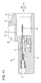
FIG. 11 is a longitudinal section of the female connector housing, -
FIG. 12 is a longitudinal section showing the state where the two connector housings are properly connected and the connection detecting member is at the standby, -
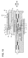
FIG. 13 is a longitudinal section showing the state where the two connector housings are properly connected and the connection detecting member is at the detection position, -
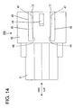
FIG. 14 is a plan view of a male connector housing in a second embodiment, and -
FIG. 15 is a front view of the male connector housing. - A first preferred embodiment of the present invention is described with reference to
FIGS. 1 to 13 . A connector of this embodiment is provided with a female connector housing 10 (as a preferred one or first connector housing), at least oneconnection detecting member 30 assembled with or provided at thefemale connector housing 10 and a male connector housing 40 (as a preferred other or second connector housing). - The
female connector housing 10 is made e.g. of synthetic resin and an integral or unitary assembly of a (preferably substantially block-shaped)terminal accommodating portion 11 and a (preferably substantially tubular)fitting portion 12 substantially in the form of a (preferably substantially rectangular or polygonal or elliptic or cylindrical) tube at least partly surrounding theterminal accommodating portion 11. One or more femaleterminal fittings 13 are to be at least partly inserted into theterminal accommodating portion 11 from an insertion side, preferably substantially from behind, and retained by one or more respective locking lances 14. The tubularfitting portion 12 is supported on (preferably the outer circumferential surface of) theterminal accommodating portion 11 preferably at or near the rear end thereof and projects substantially forward. Areceptacle 42 of themale connector housing 40 is at least partly fittable or insertable into a (preferably substantially rectangular or polygonal or elliptic or cylindrical) tubular connection space at least partly between the terminal accommodatingportion 11 and the tubularfitting portion 12. Acutout portion 16 preferably is formed in the lateral (preferably top) wall of the tubularfitting portion 12 while leaving only the front end, and the front end of the top wall of the tubularfitting portion 12 serves as a front-stop portion 17. One or more, preferably a pair of lateral (left and/or right) holdingribs 18 extending substantially in forward and backward direction FBD (directions substantially parallel to a connecting direction CD of the twoconnector housings terminal accommodating portion 11. These one or more holdingribs 18 are formed in a rear portion (preferably in a substantially rear half area) of theterminal accommodating portion 11 with respect to forward and backward direction FBD. - A
lock arm 19 is so formed at or on or in the lateral (upper) surface of theterminal accommodating portion 11 as to substantially correspond to thecutout portion 16. Thelock arm 19 preferably is substantially in the form of a horizontal (parallel to the lateral (upper) surface of the terminal accommodating portion 11) plate oblong or long substantially in forward and backward direction FBD, and a (preferably substantially rectangular) lockinghole 20 is formed to laterally or vertically penetrate (i.e. penetrate in a direction at an angle different from 0° or 180°, preferably substantially normal to the connecting direction CD) the front end of thelock arm 19, whereby a lockingportion 21 is formed at or near the front end of thelock arm 19. Thelock arm 19 is formed with one ormore leg portions 22 extending at an angle different from 0° or 180°, preferably substantially normal or downward from a longitudinal intermediate position (preferably a longitudinal center positions) thereof, and is supported on the lateral or outer (upper) surface of theterminal accommodating portion 11 at theseleg portions 22. One or more, preferably a pair of retainingprojections 23 are formed on the lateral (substantially opposite left and/or right) edge(s) of thelock arm 19. In a free state free from resilient deformation, such alock arm 19 is in a locking posture substantially in parallel with the lateral or outer (upper) surface of the terminal accommodating portion 11 (connecting direction CD of the twoconnector housings 10, 40), but is resiliently displaceable to make inclining movements like a seesaw so as to take an unlocking posture by displacing the front end outwardly or upwardly with the leg portion(s) 22 substantially as supporting points. - The
connection detecting member 30 is made e.g. of synthetic resin and preferably in the form of a substantially rectangular plate long in forward and backward direction FBD as a whole. Theconnection detecting member 30 is an integral or unitary assembly of a (preferably substantially rectangular)main portion 31, one or more, preferably a pair ofpressing portions 32 projecting substantially forward from or near the lateral (preferably substantially opposite left and/or right) end position(s) of the front end of themain portion 31, and a resilient locking piece 33 (preferably substantially in the form of a rectangular plate) extending substantially forward from (preferably the front end edge of) themain portion 31. At the lateral (preferably substantially opposite left and/or right) side(s) of the lateral or inner (bottom) surface of theconnection detecting member 30, one or more connection ribs 34 (preferably substantially having a substantially L-shaped cross section) are substantially formed from the rear end of themain portion 31 to the front ends of thepressing portions 32. One or more, preferably a pair of lateral (left and/or right) guidegrooves 35 having open inner sides are substantially continuously formed (preferably over the substantially entire length of the connection detecting member 30) by theseconnection ribs 34. Themain portion 31 and thepressing portions 32 preferably are thick to constitute rigid portions with high rigidity so as to be difficult to resiliently deform. The outer or lateral (upper) surfaces of thepressing portions 32 are cut at one or more positions behind the front end of thepressing portions 32 to form steps, thereby forming one ormore contact portions 36. One ormore locking claws 37 projecting substantially inwardly are formed at or near the front ends of thepressing portions 32. Theresilient locking piece 33 is formed such that the lower or inner surface thereof is substantially continuous with and flush with the lower surface of themain portion 31, and arranged adjacent to the pressing portion(s) 32, preferably at least partly between the lateral (left and right) pressingportions 32. Theresilient locking piece 33 is resiliently deformable in a direction intersecting the connecting direction or substantially upward and downward with the rear end thereof as a supporting point. A lockingprojection 38 substantially projecting inwardly or downwardly is formed at or near the front end of theresilient locking piece 33. - Such a
connection detecting member 30 is assembled with thelock arm 19 by engaging the one ormore guide grooves 35 with the lateral (preferably substantially opposite left and right) edge(s) of thelock arm 19 and at least partly fitting a rear portion (preferably a substantially rear half) of themain portion 31 adjacent to or at least partly between the holdingribs 18. If thelock arm 19 is inclined like a seesaw, theconnection detecting member 30 is also inclined like a seesaw substantially together with thelock arm 19. Further, by the engagement of the guide groove(s) 35 and the side edge(s) of thelock arm 19, theconnection detecting member 30 is prevented from moving relative to the lock arm 19 (backlash) in one or more directions intersecting with the connecting direction CD of the twoconnector housings 10, 40 (i.e. in vertical and/or transverse directions). By being at least partly fitted to or between the holdingribs 18, theconnection detecting member 30 is prevented from moving relative to thefemale connector housing 10 in lateral direction(s). - The
connection detecting member 30 assembled with thefemale connector housing 10 in this way is relatively movable in forward and backward direction FBD (i.e. directions substantially parallel to connecting and separating directions CD of the twoconnector housings 10, 40) between a standby position SP (seeFIGS. 2 and10 ) and a detection position DP (seeFIGS. 1 and13 ). At the standby position SP, the one ormore locking claws 37 are engaged with the one or morerespective retaining projections 23 from front to prevent a backward detachment of theconnection detecting member 30 and/or the lockingprojection 38 is engaged with the lockingportion 21 from behind to prevent a forward (toward the detection position DP) movement of theconnection detecting member 30, with the result that theconnection detecting member 30 preferably is held at the standby position SP. On the other hand, at the detection position DP, the one ormore contact portions 36 are held in contact with the at least one front-stop portion 17 to prevent a forward movement of the connectingdirection 30 and/or the lockingprojection 38 is engaged with the lockingportion 21 from front to prevent a backward (toward the standby position SP) of theconnection detecting member 30. In the moving process of theconnection detecting member 30 between the standby position SP and the detection position DP, theconnection detecting member 30 is prevented from moving relative to the lock arm (female connector housing 10) in upward, downward, leftward and/or rightward directions by the engagement of the guide groove(s) 35 and the side edge(s) of thelock arm 19 and/or the holding of themain portion 31 adjacent to or at least partly between the holdingribs 18. - The
male connector housing 40 is made e.g. of synthetic resin and an integral or unitary assembly of a (preferably substantially block shaped)terminal holding portion 41 and areceptacle 42 projecting substantially forward from theterminal holding portion 41. One or more maleterminal fittings 43 are to be at least partly inserted into theterminal holding portion 41 and retained by one or more respective locking lances 44. One ormore tabs 43a at the leading end(s) of the male terminal fitting(s) 43 project from the front end surface of theterminal holding portion 41 and are at least partly surrounded by thereceptacle 42. Alock projection 44 is formed to project outwardly or upwardly from the outer or lateral or upper surface (outer surface) of the top wall of thereceptacle 42. Thelock projection 44 preferably substantially is arranged at a lateral center position. - Similarly, one or more, preferably a pair of
guide ribs 45 extending substantially in forward and backward directions FBD are formed to project from the outer or lateral or upper surface of the lateral or top wall of thereceptacle 42. The one or more, preferably the pair ofguide ribs 45 are arranged adjacent to (preferably at the substantially opposite left and right sides of) thelock projection 44, and come substantially into sliding contact with the inner circumferential surface of the tubularfitting portion 12 in the process of connecting the twoconnector housings connector housings connector housings guide ribs 45 are gradually widened in a moving direction of theconnection detecting member 30 from the standby position SP toward the detection position DP. Preferably, the pair of left and right receiving surfaces 47 are slanted such that a spacing therebetween is gradually narrowed toward the back side of themale connector housing 40. Rear end area(s) of the receiving surface(s) 47 serve(s) as receiving portion(s) 48 for receiving a pressing force from theconnection detecting member 30. Preferably, a spacing between the front ends of the left and right receiving surfaces 47 (maximum spacing) is larger than a distance between the outer surfaces of the pair ofpressing portions 32 of theconnection detecting member 30, and/or a spacing between the rear ends of the two receiving surfaces 47 (receiving portions 48) (minimum spacing) is smaller than the distance between the outer surfaces of the pair ofpressing portions 32. - Next, functions of this embodiment are described.
- Upon connecting the two
connector housings connection detecting member 30 is positioned or held at the standby position SP and, in this state, the twoconnector housings receptacle 42 into theconnection space 15. In the connection process, the front end of thelock arm 19 comes into contact with thelock projection 44 to be resiliently displaced outwardly or upwardly and theconnection detecting member 30 is also inclined substantially together with thelock arm 19. Since the lockingprojection 38 is in contact with the lockingportion 21 in a partly connected state where the twoconnector housings connection detecting member 30 cannot move to the detection position DP. - When the two
connector housings portion 21 passes thelock projection 44. Thus, thelock projection 44 is engaged with the lockinghole 20 while or after thelock arm 19 is resiliently at least partly restored to the locking posture. Upon this engagement, themain portion 31 and thepressing portions 32 of theconnection detecting member 30 substantially return to their horizontal postures together with thelock arm 19, but theresilient locking piece 33 is resiliently deformed outwardly or upwardly relative to themain portion 31 and thepressing portions 32 since the lockingprojection 38 is still located on the outer or upper end of thelock projection 44. In this way, as shown inFIG. 12 , thelock projection 38 is disengaged from the lockingportion 21 and located above the lockingportion 21, wherefore theconnection detecting member 30 is permitted to move toward the detection position DP. Thereafter, theconnection detecting member 30 may be moved toward the detection position DP. - In a state where the two
connector housings connection detecting member 30 substantially is at the standby position SP, the front end of theconnection detecting member 30 preferably is located behind the receivingportions 48 and thepressing portions 32 and the receiving surfaces 47 are not in contact as shown inFIG. 2 . If theconnection detecting member 30 is moved forward toward the detection position DP in this state, the outer edge(s) of the front end(s) of the pressing portion(s) 32 come(s) into contact with the receiving surface(s) 47 (receiving portion(s) 48) preferably immediately before theconnection detecting member 30 reaches the detection position DP. If theconnection detecting member 30 is further moved forward in this state, thepressing portions 32 slide while strongly pressing the receivingportions 48 as if biting therein or engaging them. At this time, since both the receivingportions 48 and thepressing portions 32 have high rigidity and are difficult to resiliently deform, either or both of the receivingportions 48 and thepressing portions 32 substantially are plastically deformed. This pressing state of thepressing portion 32 against the receivingportions 48 is kept until theconnection detecting member 30 reaches the detection position. - With the
connection detecting member 30 located at the detection position DP, theconnection detecting member 30 is prevented from making relative movements (backlash) in forward and backward directions FBD, vertical directions and/or lateral directions with respect to themale connector housing 40 preferably by frictional resistance (preferably biting action) between the pressing portion(s) 32 and the receiving portion(s) 48). Here, since theconnection detecting member 30 is prevented from making relative movements in vertical and/or lateral directions with respect to thelock arm 19 and thefemale connector housing 10, relative movements (backlash) between thefemale connector housing 10 and themale connector housing 40 are also prevented in vertical and/or lateral directions. By preventing relative movements in this way, fine sliding abrasion of the femaleterminal fittings 13 and the maleterminal fittings 43 electrically connected with each other can be prevented. - As described above, in this embodiment, the
connection detecting member 30 preferably is not in contact with the receivingportions 48 when theconnection detecting member 30 is at the standby position SP. When theconnection detecting member 30 is at the detection position DP, the pressing portion(s) 32 of theconnection detecting member 30 is/are pressed against the receiving portion(s) 48 of themale connector housing 40 to produce large frictional resistance, thereby preventing theconnection detecting member 30 from making relative movements in vertical and/or lateral directions intersecting with the connecting direction CD of the twoconnector housings male connector housing 40. According to such a construction, upon connecting the twoconnector housings portions 48 by thepressing portions 32 by holding theconnection detecting member 30 at the standby position SP. Therefore, the connecting operation of the twoconnector housings - The
male connector housing 40 is formed with the one ormore guide ribs 45 that are substantially in parallel with the connecting direction CD with thefemale connector housing 10 and can come substantially into sliding contact with thefemale connector housing 10, and the one ormore receiving portions 48 are provided on the receiving surface(s) 47 different from sliding contact surface(s) 46 of the guide rib(s) 45 with thefemale connector housing 10. Since the existing guide ribs thus also function as the receivingportions 48 in this embodiment, the shape of themale connector housing 40 is simplified as compared to the case where special receiving portions separate from the guide ribs are formed. - Further, the one or
more receiving portions 48 inclined with respect to the moving direction of the connection detecting member 30 (connection direction CD) is formed preferably by gradually widening the widths of theguide ribs 45 in the moving direction of theconnection detecting member 30 from the standby position SP toward the detection position DP. Since the receiving portion(s) 48 is/are thus inclined with respect to the moving direction of theconnection detecting member 30, pressing forces of thepressing portions 32 against the receivingportions 48 increase to strengthen the biting action as theconnection detecting member 30 approaches the detection position DP, wherefore movements of theconnection detecting member 30 relative to themale connector housing 40 can be more reliably prevented. - The existing guide ribs of the connector housing before the
male connector housing 40 of this embodiment preferably are formed such that the inner surfaces thereof corresponding to the receiving surfaces are substantially parallel to the sliding contact surfaces (outer surfaces) (preferably substantially constant width over the entire length). Upon changing the shape of theguide ribs 45 to gradually widen the widths thereof, theguide ribs 45 having slanted receiving surfaces 47 (receiving portions 48) of this embodiment can be formed only by obliquely cutting the inner surfaces of cavities for the guide ribs in a mold (not shown) for molding themale connector housing 40. As described above, since it is not necessary to fabricate a new mold upon changing the shapes of the guide ribs to tapered shapes according to this embodiment, a reduction in mold cost can be promoted. - Accordingly, to reduce connection resistance, a
connection detecting member 30 is prevented from relatively moving in vertical and/or lateral directions intersecting with a connecting direction CD of twoconnector housings female connector housing 10. When being at a standby position SP, theconnection detecting member 30 is not in contact with one ormore receiving portions 48 of themale connector housing 40. When theconnection detecting member 30 is at a detection position DP, one or morepressing portions 32 of theconnection detecting member 30 press the one ormore receiving portions 48 to prevent relative movements of theconnection detecting member 30 and themale connector housing 40. At the time of connecting the twoconnector housings portions 48 by thepressing portions 32 is not produced if theconnection detecting member 30 is held at the standby position SP. - Next, a second preferred embodiment of the present invention is described with reference to
FIGS. 14 and15 . In the second embodiment, one or more, preferably a pair of lateral (left and/or right)eave portions 71 are formed to project inwardly from (preferably the top(s) of) the guide rib(s) 45 of amale connector housing 40A. Eacheave portion 71 is arranged at an angle different from 0° or 180°, preferably substantially at right angles to the corresponding receivingsurface 47 of theguide rib 45, and/or a projecting distance thereof is gradually reduced from the front end to the rear end of theguide rib 45. When viewed from above, theguide ribs 45 with theeave portions 71 preferably extend with the substantially same width in forward and backward directions FBD, and the projecting distances of theeave portions 71 are substantially zero at the rear ends of theguide ribs 45. - A spacing between the lower or inner surfaces of the
eave portions 71 and the upper or outer surface of thereceptacle 42 preferably is substantially constant in forward and backward directions FBD and/or substantially equal to a distance between upper and lower surfaces of thepressing portions 32 of the connection detecting member 30 (thickness). Spaces at least partly enclosed or defined by theeave portions 71, theguide ribs 45 and thereceptacle 42 serve asmount spaces 72 for theconnection detecting member 30, into which thepressing portions 32 are at least partly insertable while having loose movements thereof prevented. - According to the second embodiment, the pair of
pressing portions 32 can at least partly enter themount spaces 72 below theeave portions 71 as the twoconnector housings connection detecting member 30 can be reliably prevented from making outward or vertical relative movements with respect to themale connector housing 40A and, consequently, vertical backlash of the twoconnector housings - The present invention is not limited to the above described and illustrated embodiments. For example, the following embodiments are also embraced by the technical scope of the present invention as defined by the claims.
- (1) The connection detecting member may be mounted on or to or in the outer circumferential surface of the receptacle of the male connector housing, and the receiving portion(s) may be provided on or in the inner circumferential surface of the tubular fitting portion of the female connector housing.
- (2) Backlash (relative movements in directions intersecting with the connecting direction CD of the two connector housings) between the connection detecting member and the male connector housing may be prevented by at least partly sandwiching the receiving portions by the pair of pressing portions of the connection detecting member.
- (3) The connection detecting member may be so formed as not to be inclined together with the lock arm and maybe provided without touching the lock arm.
- (4) The one or more receiving portions may be provided separately from the one or more guide ribs.
- (5) The connection detecting member may be formed to be at least partly insertable into the receptacle of the male connector housing. In this case, vertical backlash of the two connector housings may be prevented by wedging the connection detecting member at least partly between the upper surface (outer surface) of the terminal accommodating portion of the female connector housing and the inner surface of the receptacle.
-
- 10
- female connector housing (one connector housing)
- 30
- connection detecting member
- 32
- pressing portion
- 40
- male connector housing (other connector housing)
- 45
- guide rib
- 48
- receiving portion
Claims (15)
- A connector, comprising:at least one pair of connector housings (10, 40) connectable with each other,at least one connection detecting member (30) assembled with a first connector housing (10) of the connector housings (10, 40) in such a manner as to prevent relative movements in directions intersecting with a connecting direction (CD) of the two connector housings (10, 40) and to permit movements between a standby position (SP) and a detection position (DP) in a direction substantially parallel to the connecting direction (CD) of the two connector housings (10, 40), andat least one restricting portion (48) provided in a second connector housing (40) of the connector housings (10, 40),wherein:the connection detecting member (30) is arranged such as not to be in contact with the restricting portion (48) when the connection detecting member (30) is at the standby position (SP), andat least one pressing portion (32) of the connection detecting member (30) presses the restricting portion (48) to prevent relative movements of the connection detecting member (30) in the directions intersecting with the connecting direction (CD) with respect to the second connector housing (40) when the connection detecting member (30) is at the detection position (DP).
- A connector according to claim 1, wherein the restricting portion (48) inclined with respect to the moving direction of the connection detecting member (30) so that pressing forces of the pressing portion (32) against the receiving portion (48) increase as the connection detecting member (30) approaches the detection position (DP).
- A connector according to one or more of the preceding claims, wherein the second connector housing (40) is formed with at least one guide rib (45) which is substantially parallel to the connecting direction (CD) and can come into sliding contact with the first connector housing (10).
- A connector according to claim 3, wherein a surface of the guide rib (45) different from a sliding contact surface with the first connector housing (10) serves as the restricting portion (48).
- A connector according to claim 3 or 4, wherein the width of the guide rib (45) is gradually widened in a moving direction of the connection detecting member (30) from the standby position (SP) toward the detection position (DP) to preferably form the restricting portion (48) inclined with respect to the moving direction of the connection detecting member (30).
- A connector according to one or more of the preceding claims 3 to 5, wherein:the guide rib (45) is formed with at least one eave portion (71) at an angle different from 0° or 180°, preferably substantially at right angles to and continuous with the restricting portion (48).
- A connector according to claim 6, wherein a mount space, into which the connection detecting member (30) is to be at least partly inserted while having loose movements thereof prevented, is defined between the eave portion (71) and the restricting portion (48).
- A connector according to one or more of the preceding claims 3 to 7, wherein the at feast one guide rib (45) on the second connector housing (40) is arranged adjacent to a lock projection (44) for locking the two connector housings (10, 40) properly connected with each other.
- A connector according to one or more of the preceding claims 3 to 8, wherein the at least one guide rib (45) comes substantially into sliding contact with an inner circumferential surface of a tubular fitting portion (12) of the first connector housing (10) in the process of connecting the two connector housings (10, 40) to substantially prevent the inclinations of the two connector housings (10, 40).
- A method of assembling a connector, comprising the following steps:providing at least one pair of connector housings (10, 40) connectable with each other, andassembling at least one connection detecting member (30) with a first connector housing (10) of the connector housings (10, 40) in such a manner as to prevent relative movements in directions intersecting with a connecting direction (CD) of the two connector housings (10, 40) and to permit movements between a standby position (SP) and a detection position (DP) in a direction substantially parallel to the connecting direction (CD) of the two connector housings (10, 40),wherein:in the assembling step the connection detecting member (30) is arranged such as- not to be in contact with the restricting portion (48) when the connection detecting member (30) is at the standby position (SP), and- when the connection detecting member (30) is at the detection position (DP) at least one pressing portion (32) of the connection detecting member (30) presses at least one restricting portion (48) in a second connector housing (40) of the connector housings (10, 40) to prevent relative movements of the connection detecting member (30) in the directions intersecting with the connecting direction (CD) with respect to the second connector housing (40).
- A method according to claim 10, further comprising a step of bringing the first connector housing (10) into sliding contact with at least one guide rib (45) which is formed at the second connector housing (40) and is substantially parallel to the connecting direction (CD).
- A method according to claim 11, wherein a surface of the guide rib (45) different from a sliding contact surface with the first connector housing (10) serves as the restricting portion (48).
- A method according to claim 11 or 12, wherein the guide rib (45) is formed with at least one eave portion (71) at an angle different from 0° or 180°, preferably substantially at right angles to and continuous with the restricting portion (48).
- A method according to claim 13, wherein the connection detecting member (30) is to be at least partly inserted, while having loose movements thereof prevented, into a mount space defined between the eave portion (71) and the restricting portion (48).
- A method according to one or more of the preceding claims 11 to 14, wherein the at least one guide rib (45) is brought substantially into sliding contact with an inner circumferential surface of a tubular fitting portion (12) of the first connector housing (10) in the process of connecting the two connector housings (10, 40) to substantially prevent the inclinations of the two connector housings (10, 40).
Applications Claiming Priority (1)
| Application Number | Priority Date | Filing Date | Title |
|---|---|---|---|
| JP2007166605A JP2009004318A (en) | 2007-06-25 | 2007-06-25 | Connector |
Publications (1)
| Publication Number | Publication Date |
|---|---|
| EP2009748A1 true EP2009748A1 (en) | 2008-12-31 |
Family
ID=39680989
Family Applications (1)
| Application Number | Title | Priority Date | Filing Date |
|---|---|---|---|
| EP08011266A Withdrawn EP2009748A1 (en) | 2007-06-25 | 2008-06-20 | A connector and assembling method therefor |
Country Status (5)
| Country | Link |
|---|---|
| US (1) | US7614904B2 (en) |
| EP (1) | EP2009748A1 (en) |
| JP (1) | JP2009004318A (en) |
| KR (1) | KR101002380B1 (en) |
| CN (1) | CN101335402B (en) |
Cited By (1)
| Publication number | Priority date | Publication date | Assignee | Title |
|---|---|---|---|---|
| WO2020157329A1 (en) * | 2019-02-01 | 2020-08-06 | Hirschmann Automotive Gmbh | Plug-in connection having a locking element |
Families Citing this family (24)
| Publication number | Priority date | Publication date | Assignee | Title |
|---|---|---|---|---|
| JP2009004318A (en) * | 2007-06-25 | 2009-01-08 | Sumitomo Wiring Syst Ltd | Connector |
| JP5050820B2 (en) * | 2007-12-05 | 2012-10-17 | 住友電装株式会社 | connector |
| DE102009032103A1 (en) * | 2009-07-08 | 2011-01-13 | Jungheinrich Aktiengesellschaft | Power unit for an engine of a truck |
| JP5486859B2 (en) * | 2009-07-09 | 2014-05-07 | 矢崎総業株式会社 | connector |
| JP5694305B2 (en) * | 2010-05-12 | 2015-04-01 | 本田技研工業株式会社 | Method for treating lignocellulosic biomass |
| JP5700811B2 (en) * | 2011-03-30 | 2015-04-15 | 矢崎総業株式会社 | connector |
| JP6138428B2 (en) * | 2012-05-29 | 2017-05-31 | 矢崎総業株式会社 | connector |
| JP2014082044A (en) * | 2012-10-15 | 2014-05-08 | Sumitomo Wiring Syst Ltd | Spring lock type connector |
| JP2014123466A (en) * | 2012-12-20 | 2014-07-03 | Sumitomo Wiring Syst Ltd | Connector |
| US9543702B2 (en) * | 2013-05-08 | 2017-01-10 | Sumitomo Wiring Systems, Ltd. | Connector |
| JP6025062B2 (en) * | 2013-10-04 | 2016-11-16 | 住友電装株式会社 | connector |
| JP6142836B2 (en) * | 2014-04-04 | 2017-06-07 | 住友電装株式会社 | connector |
| JP6149787B2 (en) * | 2014-04-14 | 2017-06-21 | 住友電装株式会社 | connector |
| JP6119670B2 (en) * | 2014-05-27 | 2017-04-26 | 住友電装株式会社 | connector |
| JP6245526B2 (en) * | 2014-10-17 | 2017-12-13 | 株式会社オートネットワーク技術研究所 | connector |
| US11090097B2 (en) * | 2015-03-17 | 2021-08-17 | Covidien Lp | Connecting end effectors to surgical devices |
| KR101592921B1 (en) * | 2015-05-12 | 2016-02-12 | 주식회사 제이티 | Universal connector |
| JP6319280B2 (en) * | 2015-12-09 | 2018-05-09 | 第一精工株式会社 | Connector device |
| FR3051080B1 (en) * | 2016-05-09 | 2022-07-22 | Delphi Int Operations Luxembourg Sarl | CONNECTION ASSEMBLY AND METHOD OF ASSEMBLING THIS CONNECTION ASSEMBLY |
| JP6806606B2 (en) * | 2017-03-23 | 2021-01-06 | 日本航空電子工業株式会社 | connector |
| JP2018181787A (en) * | 2017-04-21 | 2018-11-15 | 住友電装株式会社 | Connector |
| US11114801B2 (en) * | 2017-12-26 | 2021-09-07 | Sumitomo Wiring Systems, Ltd. | Connector |
| JP7145399B2 (en) * | 2019-03-27 | 2022-10-03 | 住友電装株式会社 | connector |
| KR102248014B1 (en) * | 2019-07-03 | 2021-05-04 | 히로세코리아 주식회사 | Connector structure for connecting board |
Citations (5)
| Publication number | Priority date | Publication date | Assignee | Title |
|---|---|---|---|---|
| US5061197A (en) * | 1989-05-19 | 1991-10-29 | Yazaki Corporation | Multi-terminal electric connector requiring low insertion and removal force |
| US20040102075A1 (en) * | 2002-10-10 | 2004-05-27 | Sumitomo Wiring Systems, Ltd. | Connector and a connector assembly |
| JP2006024435A (en) | 2004-07-07 | 2006-01-26 | Sumitomo Wiring Syst Ltd | Connector |
| EP1763114A1 (en) * | 2005-09-13 | 2007-03-14 | Sumitomo Wiring Systems, Ltd. | An electrical connector |
| US20070105420A1 (en) * | 2005-11-04 | 2007-05-10 | Yazaki Corporation | Connector |
Family Cites Families (7)
| Publication number | Priority date | Publication date | Assignee | Title |
|---|---|---|---|---|
| US5217390A (en) * | 1990-04-16 | 1993-06-08 | Sumitomo Wiring Systems, Ltd. | Connector |
| JP2003142209A (en) * | 2001-11-07 | 2003-05-16 | Sumitomo Wiring Syst Ltd | Connector |
| JP3806926B2 (en) * | 2002-03-01 | 2006-08-09 | 住友電装株式会社 | connector |
| JP4876985B2 (en) * | 2007-03-09 | 2012-02-15 | 住友電装株式会社 | connector |
| JP2009004318A (en) * | 2007-06-25 | 2009-01-08 | Sumitomo Wiring Syst Ltd | Connector |
| EP2020706B1 (en) * | 2007-08-01 | 2011-10-26 | Sumitomo Wiring Systems, Ltd. | A connector, connector assembly and connection method |
| EP2053702B1 (en) * | 2007-10-24 | 2012-06-20 | Sumitomo Wiring Systems, Ltd. | A connector device and locking structure |
-
2007
- 2007-06-25 JP JP2007166605A patent/JP2009004318A/en active Pending
-
2008
- 2008-06-20 EP EP08011266A patent/EP2009748A1/en not_active Withdrawn
- 2008-06-23 US US12/143,993 patent/US7614904B2/en not_active Expired - Fee Related
- 2008-06-25 CN CN2008101306061A patent/CN101335402B/en not_active Expired - Fee Related
- 2008-06-25 KR KR1020080060254A patent/KR101002380B1/en not_active IP Right Cessation
Patent Citations (5)
| Publication number | Priority date | Publication date | Assignee | Title |
|---|---|---|---|---|
| US5061197A (en) * | 1989-05-19 | 1991-10-29 | Yazaki Corporation | Multi-terminal electric connector requiring low insertion and removal force |
| US20040102075A1 (en) * | 2002-10-10 | 2004-05-27 | Sumitomo Wiring Systems, Ltd. | Connector and a connector assembly |
| JP2006024435A (en) | 2004-07-07 | 2006-01-26 | Sumitomo Wiring Syst Ltd | Connector |
| EP1763114A1 (en) * | 2005-09-13 | 2007-03-14 | Sumitomo Wiring Systems, Ltd. | An electrical connector |
| US20070105420A1 (en) * | 2005-11-04 | 2007-05-10 | Yazaki Corporation | Connector |
Cited By (1)
| Publication number | Priority date | Publication date | Assignee | Title |
|---|---|---|---|---|
| WO2020157329A1 (en) * | 2019-02-01 | 2020-08-06 | Hirschmann Automotive Gmbh | Plug-in connection having a locking element |
Also Published As
| Publication number | Publication date |
|---|---|
| JP2009004318A (en) | 2009-01-08 |
| KR20080114585A (en) | 2008-12-31 |
| CN101335402B (en) | 2012-05-16 |
| US7614904B2 (en) | 2009-11-10 |
| CN101335402A (en) | 2008-12-31 |
| KR101002380B1 (en) | 2010-12-20 |
| US20080318458A1 (en) | 2008-12-25 |
Similar Documents
| Publication | Publication Date | Title |
|---|---|---|
| EP2009748A1 (en) | A connector and assembling method therefor | |
| EP1701417B1 (en) | A joint connector and method of assembling it | |
| US8920187B2 (en) | Connector and connector assembly | |
| EP2637261B1 (en) | Connector, connector assembly and assembling method therefor | |
| EP1986284A2 (en) | A connector and an assembling method therefor | |
| JP2581476Y2 (en) | connector | |
| EP2416454B1 (en) | Connector | |
| US6712635B1 (en) | Connector | |
| US7223113B2 (en) | Connector and a connector assembly | |
| EP2637260A1 (en) | Connector, connector assembly and assembling method therefor | |
| EP2637262A1 (en) | Connector, connector assembly and assembling/disassembling method therefor | |
| EP1923962A1 (en) | A connector and method of preassembling it | |
| EP1830436B1 (en) | A connector, connector assembly and assembling method | |
| EP2852004A1 (en) | Terminal fitting | |
| EP2315320A1 (en) | A shorting terminal, a connector and an assembling method therefor | |
| US7306486B2 (en) | Connector | |
| JP5012072B2 (en) | Board connector | |
| EP1378968B1 (en) | A connector | |
| KR100740849B1 (en) | A connector | |
| EP1376769A1 (en) | Connector with resilient locking member | |
| EP1801926B1 (en) | A connetor and connector assembly | |
| US7753613B2 (en) | Connector | |
| EP2426790A1 (en) | Connector and connector assembly | |
| EP3355417B1 (en) | Electrical connector system with enhanced terminal retaining beam | |
| EP1811608A2 (en) | A terminal fitting and connector provided therewith |
Legal Events
| Date | Code | Title | Description |
|---|---|---|---|
| PUAI | Public reference made under article 153(3) epc to a published international application that has entered the european phase |
Free format text: ORIGINAL CODE: 0009012 |
|
| 17P | Request for examination filed |
Effective date: 20080703 |
|
| AK | Designated contracting states |
Kind code of ref document: A1 Designated state(s): AT BE BG CH CY CZ DE DK EE ES FI FR GB GR HR HU IE IS IT LI LT LU LV MC MT NL NO PL PT RO SE SI SK TR |
|
| AX | Request for extension of the european patent |
Extension state: AL BA MK RS |
|
| AKX | Designation fees paid | ||
| STAA | Information on the status of an ep patent application or granted ep patent |
Free format text: STATUS: THE APPLICATION IS DEEMED TO BE WITHDRAWN |
|
| 18D | Application deemed to be withdrawn |
Effective date: 20090701 |
|
| REG | Reference to a national code |
Ref country code: DE Ref legal event code: 8566 |