EP2008890B1 - Windscreen wiper device - Google Patents
Windscreen wiper device Download PDFInfo
- Publication number
- EP2008890B1 EP2008890B1 EP07111052A EP07111052A EP2008890B1 EP 2008890 B1 EP2008890 B1 EP 2008890B1 EP 07111052 A EP07111052 A EP 07111052A EP 07111052 A EP07111052 A EP 07111052A EP 2008890 B1 EP2008890 B1 EP 2008890B1
- Authority
- EP
- European Patent Office
- Prior art keywords
- windscreen wiper
- holding part
- windscreen
- wiper device
- wiper blade
- Prior art date
- Legal status (The legal status is an assumption and is not a legal conclusion. Google has not performed a legal analysis and makes no representation as to the accuracy of the status listed.)
- Active
Links
Images


Classifications
-
- B—PERFORMING OPERATIONS; TRANSPORTING
- B60—VEHICLES IN GENERAL
- B60S—SERVICING, CLEANING, REPAIRING, SUPPORTING, LIFTING, OR MANOEUVRING OF VEHICLES, NOT OTHERWISE PROVIDED FOR
- B60S1/00—Cleaning of vehicles
- B60S1/02—Cleaning windscreens, windows or optical devices
- B60S1/04—Wipers or the like, e.g. scrapers
- B60S1/32—Wipers or the like, e.g. scrapers characterised by constructional features of wiper blade arms or blades
- B60S1/38—Wiper blades
- B60S1/3806—Means, or measures taken, for influencing the aerodynamic quality of the wiper blades
- B60S1/381—Spoilers mounted on the squeegee or on the vertebra
-
- B—PERFORMING OPERATIONS; TRANSPORTING
- B60—VEHICLES IN GENERAL
- B60S—SERVICING, CLEANING, REPAIRING, SUPPORTING, LIFTING, OR MANOEUVRING OF VEHICLES, NOT OTHERWISE PROVIDED FOR
- B60S1/00—Cleaning of vehicles
- B60S1/02—Cleaning windscreens, windows or optical devices
- B60S1/04—Wipers or the like, e.g. scrapers
- B60S1/32—Wipers or the like, e.g. scrapers characterised by constructional features of wiper blade arms or blades
- B60S1/38—Wiper blades
- B60S1/3848—Flat-type wiper blade, i.e. without harness
- B60S1/3849—Connectors therefor; Connection to wiper arm; Attached to blade
- B60S1/3851—Mounting of connector to blade assembly
- B60S1/3855—Mounting of connector to blade assembly by welding, gluing or the like
-
- B—PERFORMING OPERATIONS; TRANSPORTING
- B60—VEHICLES IN GENERAL
- B60S—SERVICING, CLEANING, REPAIRING, SUPPORTING, LIFTING, OR MANOEUVRING OF VEHICLES, NOT OTHERWISE PROVIDED FOR
- B60S1/00—Cleaning of vehicles
- B60S1/02—Cleaning windscreens, windows or optical devices
- B60S1/04—Wipers or the like, e.g. scrapers
- B60S1/32—Wipers or the like, e.g. scrapers characterised by constructional features of wiper blade arms or blades
- B60S1/38—Wiper blades
- B60S1/3848—Flat-type wiper blade, i.e. without harness
- B60S1/3874—Flat-type wiper blade, i.e. without harness with a reinforcing vertebra
- B60S1/3875—Flat-type wiper blade, i.e. without harness with a reinforcing vertebra rectangular section
- B60S1/3881—Flat-type wiper blade, i.e. without harness with a reinforcing vertebra rectangular section in additional element, e.g. spoiler
-
- B—PERFORMING OPERATIONS; TRANSPORTING
- B60—VEHICLES IN GENERAL
- B60S—SERVICING, CLEANING, REPAIRING, SUPPORTING, LIFTING, OR MANOEUVRING OF VEHICLES, NOT OTHERWISE PROVIDED FOR
- B60S1/00—Cleaning of vehicles
- B60S1/02—Cleaning windscreens, windows or optical devices
- B60S1/04—Wipers or the like, e.g. scrapers
- B60S1/32—Wipers or the like, e.g. scrapers characterised by constructional features of wiper blade arms or blades
- B60S1/38—Wiper blades
- B60S2001/3812—Means of supporting or holding the squeegee or blade rubber
- B60S2001/3817—Means of supporting or holding the squeegee or blade rubber chacterised by a backing strip to aid mounting of squeegee in support
- B60S2001/382—Means of supporting or holding the squeegee or blade rubber chacterised by a backing strip to aid mounting of squeegee in support the backing strip being an essentially planar reinforcing strip, e.g. vertebra
-
- B—PERFORMING OPERATIONS; TRANSPORTING
- B60—VEHICLES IN GENERAL
- B60S—SERVICING, CLEANING, REPAIRING, SUPPORTING, LIFTING, OR MANOEUVRING OF VEHICLES, NOT OTHERWISE PROVIDED FOR
- B60S1/00—Cleaning of vehicles
- B60S1/02—Cleaning windscreens, windows or optical devices
- B60S1/04—Wipers or the like, e.g. scrapers
- B60S1/32—Wipers or the like, e.g. scrapers characterised by constructional features of wiper blade arms or blades
- B60S1/38—Wiper blades
- B60S2001/3812—Means of supporting or holding the squeegee or blade rubber
- B60S2001/3822—Means of supporting or holding the squeegee or blade rubber characterised by additional means to prevent longitudinal sliding of squeegee in support, e.g. clips
Definitions
- the present invention relates to a windscreen wiper device comprising an elastic, elongated carrier element, as well as an elongated wiper blade, which can be placed in abutment with a windscreen to be wiped, which wiper blade includes a central longitudinal groove, in which groove a longitudinal strip of the carrier element is disposed, which windscreen wiper device comprises a connecting device for an oscillating arm, wherein said oscillating arm can be pivotally connected to said connecting device about a pivot axis near one end.
- Such a windscreen wiper device is known from international (PCT-) patent publication no. WO 02/090155 in the name of the same Applicant.
- the prior art windscreen wiper device is in particular designed as a "yokeless" wiper device, wherein use is no longer made of several yokes pivotally connected to each other, but wherein the wiper blade is biassed by the carrier element, as a result of which it exhibits a specific curvature.
- said wiper blade includes two opposing longitudinal grooves on its longitudinal sides, in which grooves spaced-apart longitudinal strips of the carrier element are disposed. Neighbouring ends of said longitudinal strips are interconnected by said respective connecting piece.
- Said connecting device is not connected to longitudinal strip(s), as in the prior art but to said wiper blade of an elastomer material.
- the connecting device and the wiper blade are connected together so as to withstand shearing forces in a direction along said longitudinal strip.
- a soldering operation is also called a brazing operation.
- Said connecting device is welded, soldered or glued along its entire length to said wiper blade or at several distinct points along its length.
- said connecting device is welded or soldered to said wiper blade through an ultrasonic welding or soldering operation.
- a polymer material is used as a soldering material, preferably a polymer resin.
- the invention is not restricted to use with passenger cars, but it can also be used with trains and other fast vehicles.
- a windscreen wiper device according to the preamble of claim 1 is known from French patent publication no. 2,871,127 (Valeo ).
- said holding part comprises downwardly extending arms, seen in cross-section, for pivotally engaging said wiping part.
- a mechanical articulation is realized between said holding part and said wiping part, wherein said holding part holds said wiping part allowing said wiping part to make pivotal or hingeable movements relative to said holding part during use.
- said pivotal movements of said wiping part correspond to oscillatory movements of said oscillating arm. Due to said mechanical articulation said wiping part will not have to bend to follow the oscillatory movements of said oscillating arm, so that a permanent deformation of said wiping part as a result of stress in the rubber thereof is avoided.
- said wiping part particularly comprises a wiping lip, a neck extending from said wiping lip, as well as an enlarged head extending from said neck, wherein said enlarged head is mounted into a hollow chamber defined by said arms of said holding part.
- said enlarged head has a circular, elliptical, square, rectangular, rhomboid or heart-shaped cross-section.
- Said wiping lip is placed in abutment with a windscreen to be wiped.
- Said wiping lip, said neck and said enlarged head particularly are preferably in one piece and extend in longitudinal direction along the entire length of the wiper blade.
- said holding part comprise inwardly extending end parts, wherein said neck is located at least partly between said end parts, and wherein the enlarged head is located above said end parts.
- said enlarged head is confined in said hollow chamber, wherein said hook-shaped end parts further retain said wiping part onto said holding part.
- said hollow chamber comprises a lubricant in order to allow smooth pivotal movements of said wiping part without wear.
- said arms of said holding part comprise inwardly extending end parts, wherein said neck is located at least partly between said end parts, and wherein the enlarged head is located above said end parts.
- said enlarged head is confined in said hollow chamber, wherein said hook-shaped end parts further retain said wiping part onto said holding part.
- said hollow chamber comprises a lubricant in order to allow smooth pivotal movements of said wiping part without wear.
- said holding part and said wiping part extend in longitudinal direction along the entire length of said wiper blade.
- said wiper blade consists of two mutually cooperating constructional elements, namely said holding part and said wiping part.
- Said parts are preferably slidably connected to each other, wherein said enlarged head of said wiping part is slidably mounted into said hollow chamber of said holding part.
- Said hollow chamber extends along the entire length of said wiper blade so as to form a channel with two open ends.
- One of said open ends of said channel forms an entrance through which said wiping part as a separate construction element can be slid by hand into said channel until said wiping part is finally retained onto said holding part (the first position).
- Said open end also acts as an exit through which said wiping part can be slid by hand from the first position until said wiping part as a separate "loose" construction element can be replaced or repaired (the second position).
- a windscreen wiper device in accordance with the invention outer ends of said longitudinal groove are closed by a respective connecting piece connected to said wiper blade.
- Said connecting pieces or "end caps” serve to block any movement of said longitudinal strip.
- said connecting pieces or "end caps” are connected to a longitudinal horizontal side of said holding part that faces away from a windscreen to be wiped.
- said connecting pieces or "end caps” are connected to a vertical end side of said holding part.
- said connecting pieces are preferably welded, soldered or glued to said wiper blade, particularly through an ultrasonic welding or soldering operation. More in particular, a polymer material comprising a polymer resin is used therewith as a soldering material.
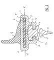
- FIGS 1 and 2 show a preferred variant of a windscreen wiper device 1 according to the invention.
- Said windscreen wiper device 1 is built up of a wiper blade 2 consisting of a plastic elongated upper holding part 3 and an elastomeric elongated lower wiping part 4, both extending in longitudinal direction along the entire length of said wiper blade 2.
- a central longitudinal groove 5 is formed, in which a longitudinal strip 6 made of spring band steel is fitted ( figures 2 ).
- Said strip 6 forms a flexible carrier element for the rubber wiper blade 2, as it were, which is thus biased in a curved position (the curvature in operative position being that of a windscreen to be wiped).
- Outer ends of said wiper blade 2 are connected on either side of the windscreen wiper device 1 to connecting pieces 7.
- the windscreen wiper device 1 is furthermore built up of a connecting device 8 of plastic material for an oscillating wiper arm 9 ( figure 1 ).
- Said connecting device 8 comprises clamping members 10 that are integral therewith, which engage round longitudinal sides 11 of the holding part 3 that face away from each other, as a result of which the connecting device 8 is firmly attached to the unit consisting of the holding part 3 and the strip 6.
- the oscillating wiper arm 9 is pivotally connected to the connecting device 8 about a pivot axis near one end thereof.
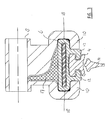
- said holding part 3 is provided with downwardly extending arms 12 in one piece therewith, seen in cross-section, thus defining a hollow chamber or space 13, again seen in cross-section.
- Said hollow chamber 13 extends in longitudinal direction along the entire length of said wiper blade 2, so as to form a channel with two open outer ends.
- said wiping part 4 consists of a wiping lip 14, a neck 15 extending from said wiping lip 14, as well as an enlarged head 16 extending from said neck 15 and having a rectangular cross-section.
- Said parts 3,4 are slidably connected to each other, wherein said enlarged head 16 of said wiping part 4 is slidably mounted into said hollow channel of said holding part 3.
- One of said open ends of said channel forms an entrance through which said wiping part 4 as a separate construction element can be slid by hand into said channel until said wiping part 4 is finally retained onto said holding part 3 (the first or holding position). Said open end also acts as an exit through which said wiping part 4 can be slid by hand from the first position until said wiping part 4 as a separate "loose" construction element can be replaced or repaired (the second position).
- the arms 12 of said holding part 3 pivotally engage the enlarged head 16 of said wiping part 4, so as to allow a pivotal or hingeable movement of said wiping part 4 when the oscillating wiper arm 9 attached to said holding part 3 makes a corresponding oscillatory movement.
- a spoiler or air deflector 17 is present either located on a side of said holding part 3 which faces away from said wiping part 4, wherein said spoiler 17 is in one piece with said holding part 3 ( figures 2 and 3 ) or attached as a detachable separate construction element thereto.
- a lubricant can be present in said channel 13.
- Said connecting device 8 and said connecting pieces 7 are particularly welded, soldered or glued to said wiper blade 2 at elongated locations indicated with reference numerals 18.
- the oscillating wiper arm 9 is connected to a mounting head fixed for rotation to a shaft driven by a small motor.
- the shaft rotates alternately in a clockwise and in a counter-clockwise sense carrying the mounting head into rotation also, which in turn draws the oscillating wiper arm 9 into rotation and by means of the connecting device 8 moves the wiper blade 2.
Landscapes
- Engineering & Computer Science (AREA)
- Mechanical Engineering (AREA)
- Physics & Mathematics (AREA)
- Fluid Mechanics (AREA)
- Quality & Reliability (AREA)
- Pivots And Pivotal Connections (AREA)
- Cleaning In General (AREA)
- Transmission Devices (AREA)
Description
- The present invention relates to a windscreen wiper device comprising an elastic, elongated carrier element, as well as an elongated wiper blade, which can be placed in abutment with a windscreen to be wiped, which wiper blade includes a central longitudinal groove, in which groove a longitudinal strip of the carrier element is disposed, which windscreen wiper device comprises a connecting device for an oscillating arm, wherein said oscillating arm can be pivotally connected to said connecting device about a pivot axis near one end.
- Such a windscreen wiper device is known from international (PCT-) patent publication no.
WO 02/090155 - A sometimes felt disadvantage of the windscreen wiper device as described in the above international (PCT-) patent publication is that it is too expensive.
- It is an object of the invention to improve the prior art, that is to improve a windscreen wiper device known from the above international (PCT-) patent publication, wherein a low cost "yokeless" wiper device or "flat blade" is proposed.
- In order to accomplish that objective, a windscreen wiper device of the kind referred to in the introduction wherein said longitudinal groove has a closed circumference, wherein said connecting device is connected to said wiper blade, wherein said wiper blade comprises an elongated upper holding part and an elongated lower wiping part of a flexible material, wherein said holding part comprises said longitudinal groove and holds said wiping part, according to the invention is characterized in that said connecting device is welded, soldered or glued to said holding part, wherein said holding part and said wiping part extend in longitudinal direction along the entire length of said wiper blade. Instead of two separate longitudinal strips inserted in two opposing longitudinal grooves in said wiper blade, now use is made of particularly one central groove having a closed circumference, thus forming a central channel for particularly one longitudinal strip. Said connecting device is not connected to longitudinal strip(s), as in the prior art but to said wiper blade of an elastomer material. In other words, the connecting device and the wiper blade are connected together so as to withstand shearing forces in a direction along said longitudinal strip. In practice, a soldering operation is also called a brazing operation. Said connecting device is welded, soldered or glued along its entire length to said wiper blade or at several distinct points along its length. Preferably, said connecting device is welded or soldered to said wiper blade through an ultrasonic welding or soldering operation. More particularly, a polymer material is used as a soldering material, preferably a polymer resin.
- It is noted that the invention is not restricted to use with passenger cars, but it can also be used with trains and other fast vehicles.
- A windscreen wiper device according to the preamble of claim 1 is known from French patent publication no.
2,871,127 (Valeo - Particularly, said holding part comprises downwardly extending arms, seen in cross-section, for pivotally engaging said wiping part. In other words, a mechanical articulation is realized between said holding part and said wiping part, wherein said holding part holds said wiping part allowing said wiping part to make pivotal or hingeable movements relative to said holding part during use. In use said pivotal movements of said wiping part correspond to oscillatory movements of said oscillating arm. Due to said mechanical articulation said wiping part will not have to bend to follow the oscillatory movements of said oscillating arm, so that a permanent deformation of said wiping part as a result of stress in the rubber thereof is avoided. Please note that a sometimes felt disadvantage of the windscreen wiper device as described in the above international (PCT-) patent publication is that a rubber wiping lip of said wiper blade might show a permanent deformation after several months of use, as said wiping lip has to make many oscillating movements during use, wherein said wiping lip has to bend severely. Bending the rubber of said wiping lip many times back and forth might lead to a permanent deformation of said rubber and thus to deteriorated wiping properties, with all negative consequences involved.
- Experiments of the present invention have shown that said wiping part particularly comprises a wiping lip, a neck extending from said wiping lip, as well as an enlarged head extending from said neck, wherein said enlarged head is mounted into a hollow chamber defined by said arms of said holding part. Preferably, said enlarged head has a circular, elliptical, square, rectangular, rhomboid or heart-shaped cross-section. Said wiping lip is placed in abutment with a windscreen to be wiped. Said wiping lip, said neck and said enlarged head particularly are preferably in one piece and extend in longitudinal direction along the entire length of the wiper blade. In particular, said holding part comprise inwardly extending end parts, wherein said neck is located at least partly between said end parts, and wherein the enlarged head is located above said end parts. In other words, said enlarged head is confined in said hollow chamber, wherein said hook-shaped end parts further retain said wiping part onto said holding part. Particularly, said hollow chamber comprises a lubricant in order to allow smooth pivotal movements of said wiping part without wear. More in particular, said arms of said holding part comprise inwardly extending end parts, wherein said neck is located at least partly between said end parts, and wherein the enlarged head is located above said end parts. In other words, said enlarged head is confined in said hollow chamber, wherein said hook-shaped end parts further retain said wiping part onto said holding part. Particularly, said hollow chamber comprises a lubricant in order to allow smooth pivotal movements of said wiping part without wear.
- It is noted that in the invention said holding part and said wiping part extend in longitudinal direction along the entire length of said wiper blade. In other words, said wiper blade consists of two mutually cooperating constructional elements, namely said holding part and said wiping part. Said parts are preferably slidably connected to each other, wherein said enlarged head of said wiping part is slidably mounted into said hollow chamber of said holding part. Said hollow chamber extends along the entire length of said wiper blade so as to form a channel with two open ends. One of said open ends of said channel forms an entrance through which said wiping part as a separate construction element can be slid by hand into said channel until said wiping part is finally retained onto said holding part (the first position). Said open end also acts as an exit through which said wiping part can be slid by hand from the first position until said wiping part as a separate "loose" construction element can be replaced or repaired (the second position).
- In another preferred embodiment of a windscreen wiper device in accordance with the invention outer ends of said longitudinal groove are closed by a respective connecting piece connected to said wiper blade. Said connecting pieces or "end caps" serve to block any movement of said longitudinal strip. In a preferred embodiment said connecting pieces or "end caps" are connected to a longitudinal horizontal side of said holding part that faces away from a windscreen to be wiped. In addition thereto or instead thereof said connecting pieces or "end caps" are connected to a vertical end side of said holding part.
- It is noted that what has been indicated above regarding welding, soldering or glueing of said connecting device, also applies here to welding, soldering or glueing of said connecting pieces. In other words, said connecting pieces are preferably welded, soldered or glued to said wiper blade, particularly through an ultrasonic welding or soldering operation. More in particular, a polymer material comprising a polymer resin is used therewith as a soldering material.
- The invention will now be explained in more detail with reference to figures illustrated in a drawing, wherein:
-
figure 1 shows a perspective view of a windscreen wiper device according to a preferred embodiment of the invention; -
figures 2 and3 are a cross-section of the windscreen wiper device offigure 1 at the location of a connecting device for an oscillating arm and at another location outside the connecting device, respectively; -
figure 4 is a cross-section of the windscreen wiper device offigure 1 at the location of a connecting piece at both ends of a wiper blade thereof. -
Figures 1 and2 show a preferred variant of a windscreen wiper device 1 according to the invention. Said windscreen wiper device 1 is built up of a wiper blade 2 consisting of a plastic elongated upper holding part 3 and an elastomeric elongatedlower wiping part 4, both extending in longitudinal direction along the entire length of said wiper blade 2. In the holding part 3 a centrallongitudinal groove 5 is formed, in which alongitudinal strip 6 made of spring band steel is fitted (figures 2 ). Saidstrip 6 forms a flexible carrier element for the rubber wiper blade 2, as it were, which is thus biased in a curved position (the curvature in operative position being that of a windscreen to be wiped). Outer ends of said wiper blade 2 are connected on either side of the windscreen wiper device 1 to connectingpieces 7. - The windscreen wiper device 1 is furthermore built up of a connecting device 8 of plastic material for an oscillating wiper arm 9 (
figure 1 ). Said connecting device 8 comprises clampingmembers 10 that are integral therewith, which engage roundlongitudinal sides 11 of the holding part 3 that face away from each other, as a result of which the connecting device 8 is firmly attached to the unit consisting of the holding part 3 and thestrip 6. The oscillating wiper arm 9 is pivotally connected to the connecting device 8 about a pivot axis near one end thereof. - As can be seen from
figures 2 and3 , said holding part 3 is provided with downwardly extendingarms 12 in one piece therewith, seen in cross-section, thus defining a hollow chamber or space 13, again seen in cross-section. Said hollow chamber 13 extends in longitudinal direction along the entire length of said wiper blade 2, so as to form a channel with two open outer ends. Again referring tofigures 2 and3 , saidwiping part 4 consists of awiping lip 14, aneck 15 extending from saidwiping lip 14, as well as an enlargedhead 16 extending fromsaid neck 15 and having a rectangular cross-section. Saidparts 3,4 are slidably connected to each other, wherein said enlargedhead 16 of saidwiping part 4 is slidably mounted into said hollow channel of said holding part 3. One of said open ends of said channel forms an entrance through which said wipingpart 4 as a separate construction element can be slid by hand into said channel until said wipingpart 4 is finally retained onto said holding part 3 (the first or holding position). Said open end also acts as an exit through which said wipingpart 4 can be slid by hand from the first position until said wipingpart 4 as a separate "loose" construction element can be replaced or repaired (the second position). Thearms 12 of said holding part 3 pivotally engage theenlarged head 16 of said wipingpart 4, so as to allow a pivotal or hingeable movement of said wipingpart 4 when the oscillating wiper arm 9 attached to said holding part 3 makes a corresponding oscillatory movement. - A spoiler or
air deflector 17 is present either located on a side of said holding part 3 which faces away from said wipingpart 4, wherein saidspoiler 17 is in one piece with said holding part 3 (figures 2 and3 ) or attached as a detachable separate construction element thereto. A lubricant can be present in said channel 13. - Said connecting device 8 and said connecting
pieces 7 are particularly welded, soldered or glued to said wiper blade 2 at elongated locations indicated withreference numerals 18. - Although not depicted in the figures, it will be clear for a person skilled in the art that the oscillating wiper arm 9 is connected to a mounting head fixed for rotation to a shaft driven by a small motor. In use, the shaft rotates alternately in a clockwise and in a counter-clockwise sense carrying the mounting head into rotation also, which in turn draws the oscillating wiper arm 9 into rotation and by means of the connecting device 8 moves the wiper blade 2.
- The invention is not restricted to the embodiments shown, but also extends to other preferred variants falling within the scope of the appended claims. For example, a skilled person would easily understand that the central
longitudinal strip 6 offigures 2 and3 could well be replaced by twolongitudinal strips 6 located in correspondingly shapedgrooves 5 in said holding part 3.
Claims (13)
- A windscreen wiper device (1) comprising an elastic, elongated carrier element, as well as an elongated wiper blade (2) made of an elastomer material, which can be placed in butment with a windscreen to be wiped, which wiper blade (2) includes a central longitudinal groove (5), in which groove (5) a longitudinal strip (6) of the carrier element is disposed, which windscreen wiper device (1) comprises a connecting device (8) for an oscillating arm (9), wherein said oscillating arm (9) can be pivotally connected to said connecting device (8) about a pivot axis near one end, wherein said longitudinal groove (5) has a closed circumference, wherein said connecting device (8) is connected to said wiper blade (2), wherein said wiper blade (2) comprises an elongated upper holding part (3) and an elongated lower wiping part (4) of a flexible material, wherein said holding part (3) comprises said longitudinal groove (5) and holds said wiping part (4), wherein said holding part (3) and said wiping part (4) extend in longitudinal direction along the entire length of said wiper blade (2), characterized in that said connecting device (8) is welded, soldered or glued to said holding part (3), wherein said connecting device (8) is not connected to the longitudinal strip (6).
- A windscreen wiper device (1) according to claim 1,
wherein said connecting device (8) is connected to longitudinal vertical sides (18) of said holding part (3) that face away from each other. - A windscreen wiper device (1) according to claim 1 or 2, wherein said connecting device (8) is connected to a longitudinal horizontal side of said holding part (3) that faces towards a windscreen to be wiped.
- A windscreen wiper device (1) according to claim 1, 2 or 3, wherein said connecting device (8) is welded or soldered to said wiper blade (2) through an ultrasonic welding or soldering operation.
- A windscreen wiper device (1) according to claim 4,
wherein a polymer material is used as a soldering material. - A windscreen wiper device (1) according to claim 5, wherein said polymer material comprises a polymer resin.
- A windscreen wiper device (1) according to any of the preceding claims 1 through 6, wherein outer ends of said longitudinal groove (5) are closed by a respective connecting piece (7) connected to said wiper blade (2).
- A windscreen wiper device (1) according to claim 7,
wherein said connecting pieces (7) are connected to a longitudinal horizontal side (18) of said holding part (3) that faces away from a windscreen to be wiped. - A windscreen wiper device (1) according to claim 7 or 8, wherein said connecting pieces (7) are connected to a vertical end side (18) of said holding part (3).
- A windscreen wiper device (1) according to claim 7, 8 or 9, wherein said connecting pieces (7) are welded, soldered or glued to said wiper blade (2).
- A windscreen wiper device (1) according to claim 10,
wherein said connecting pieces (7) are welded or soldered to said wiper blade (2) through an ultrasonic welding or soldering operation. - A windscreen wiper device (1) according to claim 10 or 11, wherein a polymer material is used as a soldering material.
- A windscreen wiper device (1) according to claim 12, wherein said polymer material comprises a polymer resin.
Priority Applications (7)
| Application Number | Priority Date | Filing Date | Title |
|---|---|---|---|
| ES07111052T ES2397097T3 (en) | 2007-06-26 | 2007-06-26 | Windshield wiper device |
| EP07111052A EP2008890B1 (en) | 2007-06-26 | 2007-06-26 | Windscreen wiper device |
| US12/666,901 US9862355B2 (en) | 2007-06-26 | 2008-06-17 | Windscreen wiper device |
| JP2010513849A JP5366268B2 (en) | 2007-06-26 | 2008-06-17 | Windshield wiper device |
| KR1020107000575A KR101493114B1 (en) | 2007-06-26 | 2008-06-17 | Windscreen wiper device |
| CN2008800221806A CN101687493B (en) | 2007-06-26 | 2008-06-17 | Windscreen wiper device |
| PCT/EP2008/057634 WO2009000706A1 (en) | 2007-06-26 | 2008-06-17 | Windscreen wiper device |
Applications Claiming Priority (1)
| Application Number | Priority Date | Filing Date | Title |
|---|---|---|---|
| EP07111052A EP2008890B1 (en) | 2007-06-26 | 2007-06-26 | Windscreen wiper device |
Publications (2)
| Publication Number | Publication Date |
|---|---|
| EP2008890A1 EP2008890A1 (en) | 2008-12-31 |
| EP2008890B1 true EP2008890B1 (en) | 2012-10-03 |
Family
ID=38709725
Family Applications (1)
| Application Number | Title | Priority Date | Filing Date |
|---|---|---|---|
| EP07111052A Active EP2008890B1 (en) | 2007-06-26 | 2007-06-26 | Windscreen wiper device |
Country Status (7)
| Country | Link |
|---|---|
| US (1) | US9862355B2 (en) |
| EP (1) | EP2008890B1 (en) |
| JP (1) | JP5366268B2 (en) |
| KR (1) | KR101493114B1 (en) |
| CN (1) | CN101687493B (en) |
| ES (1) | ES2397097T3 (en) |
| WO (1) | WO2009000706A1 (en) |
Families Citing this family (9)
| Publication number | Priority date | Publication date | Assignee | Title |
|---|---|---|---|---|
| DE602007012529D1 (en) * | 2007-06-27 | 2011-03-31 | Federal Mogul Sa | Windshield wiper device |
| US20100139026A1 (en) * | 2008-12-04 | 2010-06-10 | Chin Pech Co., Ltd. | Wiper Blade Spoiler Assembly |
| DE102010062896A1 (en) * | 2010-12-13 | 2012-06-14 | Robert Bosch Gmbh | Wiper blade device |
| JP2014509985A (en) * | 2011-04-07 | 2014-04-24 | フェデラル−モグル エス.エー. | Windshield wiper device |
| DE102011078186A1 (en) * | 2011-06-28 | 2013-01-03 | Robert Bosch Gmbh | Wiper device, in particular motor vehicle windshield wiper device |
| DE102011078185A1 (en) * | 2011-06-28 | 2013-01-03 | Robert Bosch Gmbh | Wiper device, in particular motor vehicle windshield wiper device |
| FR2997052B1 (en) * | 2012-10-24 | 2015-07-03 | Valeo Systemes Dessuyage | WIPER ASSEMBLY COMPRISING A BRUSHED CONNECTING MEMBER |
| CN105283358A (en) * | 2013-04-12 | 2016-01-27 | 费德罗-莫格尔公司 | Windscreen wiper device |
| FR3033300B1 (en) * | 2015-03-03 | 2018-10-26 | Valeo Systemes D'essuyage | WIPER BLADE FOR A VEHICLE WIPER SYSTEM |
Citations (2)
| Publication number | Priority date | Publication date | Assignee | Title |
|---|---|---|---|---|
| WO2006088808A1 (en) * | 2005-02-14 | 2006-08-24 | Tenneco Automotive Operating Company Inc. | Encapsulated beam with anti-rotation system |
| EP1745997A1 (en) * | 2005-07-19 | 2007-01-24 | Federal-Mogul S.A. | Windscreen wiper device |
Family Cites Families (22)
| Publication number | Priority date | Publication date | Assignee | Title |
|---|---|---|---|---|
| JPH0354051A (en) * | 1989-07-22 | 1991-03-08 | Nitto Kagaku Kk | Oil film removing wiper blade |
| EP0783998B1 (en) * | 1996-01-10 | 2000-10-11 | Cooper Automotive S.A. | Windshield wiper |
| DE19627115A1 (en) * | 1996-07-05 | 1998-01-08 | Bosch Gmbh Robert | Wiper blade for windows of motor vehicles |
| US6397428B2 (en) * | 1997-05-02 | 2002-06-04 | Robert Bosch Gmbh | Wiper blade for motor vehicle windows with support having connection device with projections and welding connection |
| DE19718490A1 (en) * | 1997-05-02 | 1998-11-05 | Bosch Gmbh Robert | Wiper blade for windows of motor vehicles |
| DE19745006A1 (en) * | 1997-10-11 | 1999-04-22 | Bosch Gmbh Robert | Wiper system, especially for windscreens of motor vehicles |
| DE19801058A1 (en) * | 1998-01-14 | 1999-07-15 | Bosch Gmbh Robert | Motor vehicle windscreen wiper blade with curved spring rail |
| DE10025706A1 (en) * | 2000-05-25 | 2001-11-29 | Bosch Gmbh Robert | Wiper blade for cleaning vehicle windows |
| DE10033779A1 (en) * | 2000-07-12 | 2002-05-02 | Valeo Auto Electric Gmbh | Wiper device, in particular for motor vehicles |
| DE10114476B4 (en) * | 2001-03-24 | 2015-11-19 | Robert Bosch Gmbh | Windscreen wiper and method for its production |
| ES2245340T3 (en) | 2001-05-08 | 2006-01-01 | Federal-Mogul S.A. | WINDSHIELD CLEANING DEVICE. |
| JP3898186B2 (en) * | 2003-02-14 | 2007-03-28 | ケーシーダブリュー コーポレーション | Wiper blade assembly for vehicle |
| ES2269918T3 (en) * | 2003-09-05 | 2007-04-01 | Federal-Mogul S.A. | WINDSHIELD CLEANING DEVICE. |
| FR2868747B1 (en) * | 2004-04-07 | 2008-06-20 | Valeo Systemes Dessuyage | FLAT-BLADE TYPE WIPER BLADE COMPRISING AERODYNAMIC DEFLECTOR |
| FR2871127B1 (en) * | 2004-06-03 | 2007-09-07 | Valeo Systemes Dessuyage | FLAT WIPER BLADE IN PARTICULAR FOR A MOTOR VEHICLE |
| BRMU8402004U (en) * | 2004-08-17 | 2004-12-28 | Dyna Electromecanica | Reed arrangement |
| FR2885103B1 (en) * | 2005-04-29 | 2007-06-29 | Valeo Systemes Dessuyage | MOUNTING BRACKET FOR A WIPER BLADE AT THE END OF A TRAINING ARM MADE OF TWO PARTS |
| US7350259B2 (en) * | 2005-07-28 | 2008-04-01 | Tenneco Automotive Operating Company Inc. | Relative axial translation prevention system for wiper blade assemblies |
| US20070022556A1 (en) * | 2005-07-28 | 2007-02-01 | Walworth Van T | Wind deflector with symmetrical geometry |
| FR2891227A1 (en) * | 2005-09-23 | 2007-03-30 | Valeo Systemes Dessuyage | Connector for attaching windscreen wiper blades to arms consists of two mirror-image sections, each having vertical upper wall and wider lower part with U-shaped cross-section, lower parts enclosing slot which fits around blade holder |
| DE102005062462B4 (en) | 2005-12-27 | 2020-08-06 | Robert Bosch Gmbh | Wiper blade |
| US7861363B2 (en) * | 2006-02-02 | 2011-01-04 | Trico Products Corporation | Beam blade windshield wiper assembly having an airfoil |
-
2007
- 2007-06-26 ES ES07111052T patent/ES2397097T3/en active Active
- 2007-06-26 EP EP07111052A patent/EP2008890B1/en active Active
-
2008
- 2008-06-17 JP JP2010513849A patent/JP5366268B2/en not_active Expired - Fee Related
- 2008-06-17 KR KR1020107000575A patent/KR101493114B1/en active IP Right Grant
- 2008-06-17 WO PCT/EP2008/057634 patent/WO2009000706A1/en active Application Filing
- 2008-06-17 US US12/666,901 patent/US9862355B2/en not_active Expired - Fee Related
- 2008-06-17 CN CN2008800221806A patent/CN101687493B/en not_active Expired - Fee Related
Patent Citations (2)
| Publication number | Priority date | Publication date | Assignee | Title |
|---|---|---|---|---|
| WO2006088808A1 (en) * | 2005-02-14 | 2006-08-24 | Tenneco Automotive Operating Company Inc. | Encapsulated beam with anti-rotation system |
| EP1745997A1 (en) * | 2005-07-19 | 2007-01-24 | Federal-Mogul S.A. | Windscreen wiper device |
Also Published As
| Publication number | Publication date |
|---|---|
| WO2009000706A1 (en) | 2008-12-31 |
| CN101687493A (en) | 2010-03-31 |
| US9862355B2 (en) | 2018-01-09 |
| CN101687493B (en) | 2012-07-04 |
| ES2397097T3 (en) | 2013-03-04 |
| JP2010531264A (en) | 2010-09-24 |
| JP5366268B2 (en) | 2013-12-11 |
| KR20100038194A (en) | 2010-04-13 |
| US20100299862A1 (en) | 2010-12-02 |
| EP2008890A1 (en) | 2008-12-31 |
| KR101493114B1 (en) | 2015-02-12 |
Similar Documents
| Publication | Publication Date | Title |
|---|---|---|
| EP2008891B1 (en) | Windscreen wiper device | |
| EP2008890B1 (en) | Windscreen wiper device | |
| EP2103490A1 (en) | Windscreen wiper device | |
| EP1964732A1 (en) | Windscreen wiper device | |
| EP2042394B1 (en) | Windscreen wiper device | |
| EP2103489A1 (en) | Windscreen wiper device | |
| US10369969B2 (en) | Windscreen wiper device | |
| EP2090479B1 (en) | Windscreen wiper device | |
| EP2470401B1 (en) | A windscreen wiper device | |
| EP2670636B1 (en) | Windscreen wiper device | |
| US20080184516A1 (en) | Windscreen Wiper Arm | |
| EP2585344B1 (en) | A windscreen wiper device | |
| EP2670635B1 (en) | A windscreen wiper device |
Legal Events
| Date | Code | Title | Description |
|---|---|---|---|
| PUAI | Public reference made under article 153(3) epc to a published international application that has entered the european phase |
Free format text: ORIGINAL CODE: 0009012 |
|
| AK | Designated contracting states |
Kind code of ref document: A1 Designated state(s): AT BE BG CH CY CZ DE DK EE ES FI FR GB GR HU IE IS IT LI LT LU LV MC MT NL PL PT RO SE SI SK TR |
|
| AX | Request for extension of the european patent |
Extension state: AL BA HR MK RS |
|
| 17P | Request for examination filed |
Effective date: 20090612 |
|
| 17Q | First examination report despatched |
Effective date: 20090728 |
|
| AKX | Designation fees paid |
Designated state(s): BE DE ES FR GB IT |
|
| GRAP | Despatch of communication of intention to grant a patent |
Free format text: ORIGINAL CODE: EPIDOSNIGR1 |
|
| GRAS | Grant fee paid |
Free format text: ORIGINAL CODE: EPIDOSNIGR3 |
|
| GRAA | (expected) grant |
Free format text: ORIGINAL CODE: 0009210 |
|
| AK | Designated contracting states |
Kind code of ref document: B1 Designated state(s): BE DE ES FR GB IT |
|
| REG | Reference to a national code |
Ref country code: GB Ref legal event code: FG4D |
|
| REG | Reference to a national code |
Ref country code: DE Ref legal event code: R096 Ref document number: 602007025819 Country of ref document: DE Effective date: 20121129 |
|
| REG | Reference to a national code |
Ref country code: ES Ref legal event code: FG2A Ref document number: 2397097 Country of ref document: ES Kind code of ref document: T3 Effective date: 20130304 |
|
| PLBE | No opposition filed within time limit |
Free format text: ORIGINAL CODE: 0009261 |
|
| STAA | Information on the status of an ep patent application or granted ep patent |
Free format text: STATUS: NO OPPOSITION FILED WITHIN TIME LIMIT |
|
| 26N | No opposition filed |
Effective date: 20130704 |
|
| REG | Reference to a national code |
Ref country code: DE Ref legal event code: R097 Ref document number: 602007025819 Country of ref document: DE Effective date: 20130704 |
|
| PG25 | Lapsed in a contracting state [announced via postgrant information from national office to epo] |
Ref country code: IT Free format text: LAPSE BECAUSE OF NON-PAYMENT OF DUE FEES Effective date: 20130626 |
|
| REG | Reference to a national code |
Ref country code: FR Ref legal event code: PLFP Year of fee payment: 10 |
|
| PGFP | Annual fee paid to national office [announced via postgrant information from national office to epo] |
Ref country code: ES Payment date: 20160606 Year of fee payment: 10 Ref country code: GB Payment date: 20160525 Year of fee payment: 10 |
|
| REG | Reference to a national code |
Ref country code: FR Ref legal event code: PLFP Year of fee payment: 11 |
|
| GBPC | Gb: european patent ceased through non-payment of renewal fee |
Effective date: 20170626 |
|
| PG25 | Lapsed in a contracting state [announced via postgrant information from national office to epo] |
Ref country code: GB Free format text: LAPSE BECAUSE OF NON-PAYMENT OF DUE FEES Effective date: 20170626 |
|
| REG | Reference to a national code |
Ref country code: FR Ref legal event code: PLFP Year of fee payment: 12 |
|
| REG | Reference to a national code |
Ref country code: ES Ref legal event code: FD2A Effective date: 20181113 |
|
| PG25 | Lapsed in a contracting state [announced via postgrant information from national office to epo] |
Ref country code: ES Free format text: LAPSE BECAUSE OF NON-PAYMENT OF DUE FEES Effective date: 20170627 |
|
| PGFP | Annual fee paid to national office [announced via postgrant information from national office to epo] |
Ref country code: DE Payment date: 20190612 Year of fee payment: 13 |
|
| PGFP | Annual fee paid to national office [announced via postgrant information from national office to epo] |
Ref country code: FR Payment date: 20190510 Year of fee payment: 13 |
|
| REG | Reference to a national code |
Ref country code: DE Ref legal event code: R119 Ref document number: 602007025819 Country of ref document: DE |
|
| PG25 | Lapsed in a contracting state [announced via postgrant information from national office to epo] |
Ref country code: FR Free format text: LAPSE BECAUSE OF NON-PAYMENT OF DUE FEES Effective date: 20200630 |
|
| PG25 | Lapsed in a contracting state [announced via postgrant information from national office to epo] |
Ref country code: DE Free format text: LAPSE BECAUSE OF NON-PAYMENT OF DUE FEES Effective date: 20210101 |
|
| PGFP | Annual fee paid to national office [announced via postgrant information from national office to epo] |
Ref country code: BE Payment date: 20230627 Year of fee payment: 17 |