EP2007451B1 - Dose information device - Google Patents
Dose information device Download PDFInfo
- Publication number
- EP2007451B1 EP2007451B1 EP07712318.0A EP07712318A EP2007451B1 EP 2007451 B1 EP2007451 B1 EP 2007451B1 EP 07712318 A EP07712318 A EP 07712318A EP 2007451 B1 EP2007451 B1 EP 2007451B1
- Authority
- EP
- European Patent Office
- Prior art keywords
- dose
- prescribed
- setting
- information member
- back cover
- Prior art date
- Legal status (The legal status is an assumption and is not a legal conclusion. Google has not performed a legal analysis and makes no representation as to the accuracy of the status listed.)
- Not-in-force
Links
- 239000003814 drug Substances 0.000 claims description 37
- 238000012384 transportation and delivery Methods 0.000 claims description 31
- 229910000831 Steel Inorganic materials 0.000 description 5
- 239000010959 steel Substances 0.000 description 5
- 239000007788 liquid Substances 0.000 description 4
- 238000002347 injection Methods 0.000 description 3
- 239000007924 injection Substances 0.000 description 3
- 239000007921 spray Substances 0.000 description 3
- 239000003550 marker Substances 0.000 description 2
- 239000000443 aerosol Substances 0.000 description 1
- 230000001419 dependent effect Effects 0.000 description 1
- 239000000843 powder Substances 0.000 description 1
Images


Classifications
-
- A—HUMAN NECESSITIES
- A61—MEDICAL OR VETERINARY SCIENCE; HYGIENE
- A61M—DEVICES FOR INTRODUCING MEDIA INTO, OR ONTO, THE BODY; DEVICES FOR TRANSDUCING BODY MEDIA OR FOR TAKING MEDIA FROM THE BODY; DEVICES FOR PRODUCING OR ENDING SLEEP OR STUPOR
- A61M5/00—Devices for bringing media into the body in a subcutaneous, intra-vascular or intramuscular way; Accessories therefor, e.g. filling or cleaning devices, arm-rests
- A61M5/178—Syringes
- A61M5/31—Details
- A61M5/315—Pistons; Piston-rods; Guiding, blocking or restricting the movement of the rod or piston; Appliances on the rod for facilitating dosing ; Dosing mechanisms
- A61M5/31533—Dosing mechanisms, i.e. setting a dose
- A61M5/31545—Setting modes for dosing
- A61M5/31548—Mechanically operated dose setting member
- A61M5/3155—Mechanically operated dose setting member by rotational movement of dose setting member, e.g. during setting or filling of a syringe
- A61M5/31551—Mechanically operated dose setting member by rotational movement of dose setting member, e.g. during setting or filling of a syringe including axial movement of dose setting member
-
- A—HUMAN NECESSITIES
- A61—MEDICAL OR VETERINARY SCIENCE; HYGIENE
- A61M—DEVICES FOR INTRODUCING MEDIA INTO, OR ONTO, THE BODY; DEVICES FOR TRANSDUCING BODY MEDIA OR FOR TAKING MEDIA FROM THE BODY; DEVICES FOR PRODUCING OR ENDING SLEEP OR STUPOR
- A61M15/00—Inhalators
- A61M15/0065—Inhalators with dosage or measuring devices
- A61M15/0066—Inhalators with dosage or measuring devices with means for varying the dose size
-
- A—HUMAN NECESSITIES
- A61—MEDICAL OR VETERINARY SCIENCE; HYGIENE
- A61M—DEVICES FOR INTRODUCING MEDIA INTO, OR ONTO, THE BODY; DEVICES FOR TRANSDUCING BODY MEDIA OR FOR TAKING MEDIA FROM THE BODY; DEVICES FOR PRODUCING OR ENDING SLEEP OR STUPOR
- A61M15/00—Inhalators
- A61M15/0065—Inhalators with dosage or measuring devices
- A61M15/0068—Indicating or counting the number of dispensed doses or of remaining doses
- A61M15/007—Mechanical counters
- A61M15/0071—Mechanical counters having a display or indicator
- A61M15/0073—Mechanical counters having a display or indicator on a ring
-
- A—HUMAN NECESSITIES
- A61—MEDICAL OR VETERINARY SCIENCE; HYGIENE
- A61M—DEVICES FOR INTRODUCING MEDIA INTO, OR ONTO, THE BODY; DEVICES FOR TRANSDUCING BODY MEDIA OR FOR TAKING MEDIA FROM THE BODY; DEVICES FOR PRODUCING OR ENDING SLEEP OR STUPOR
- A61M15/00—Inhalators
- A61M15/0065—Inhalators with dosage or measuring devices
- A61M15/0068—Indicating or counting the number of dispensed doses or of remaining doses
- A61M15/007—Mechanical counters
- A61M15/0071—Mechanical counters having a display or indicator
- A61M15/0076—Mechanical counters having a display or indicator on a drum
-
- A—HUMAN NECESSITIES
- A61—MEDICAL OR VETERINARY SCIENCE; HYGIENE
- A61M—DEVICES FOR INTRODUCING MEDIA INTO, OR ONTO, THE BODY; DEVICES FOR TRANSDUCING BODY MEDIA OR FOR TAKING MEDIA FROM THE BODY; DEVICES FOR PRODUCING OR ENDING SLEEP OR STUPOR
- A61M15/00—Inhalators
- A61M15/0065—Inhalators with dosage or measuring devices
- A61M15/0068—Indicating or counting the number of dispensed doses or of remaining doses
- A61M15/007—Mechanical counters
- A61M15/0071—Mechanical counters having a display or indicator
- A61M15/0078—Mechanical counters having a display or indicator on a strip
-
- A—HUMAN NECESSITIES
- A61—MEDICAL OR VETERINARY SCIENCE; HYGIENE
- A61M—DEVICES FOR INTRODUCING MEDIA INTO, OR ONTO, THE BODY; DEVICES FOR TRANSDUCING BODY MEDIA OR FOR TAKING MEDIA FROM THE BODY; DEVICES FOR PRODUCING OR ENDING SLEEP OR STUPOR
- A61M15/00—Inhalators
- A61M15/08—Inhaling devices inserted into the nose
-
- A—HUMAN NECESSITIES
- A61—MEDICAL OR VETERINARY SCIENCE; HYGIENE
- A61M—DEVICES FOR INTRODUCING MEDIA INTO, OR ONTO, THE BODY; DEVICES FOR TRANSDUCING BODY MEDIA OR FOR TAKING MEDIA FROM THE BODY; DEVICES FOR PRODUCING OR ENDING SLEEP OR STUPOR
- A61M5/00—Devices for bringing media into the body in a subcutaneous, intra-vascular or intramuscular way; Accessories therefor, e.g. filling or cleaning devices, arm-rests
- A61M5/178—Syringes
- A61M5/20—Automatic syringes, e.g. with automatically actuated piston rod, with automatic needle injection, filling automatically
- A61M2005/2006—Having specific accessories
- A61M2005/2013—Having specific accessories triggering of discharging means by contact of injector with patient body
-
- A—HUMAN NECESSITIES
- A61—MEDICAL OR VETERINARY SCIENCE; HYGIENE
- A61M—DEVICES FOR INTRODUCING MEDIA INTO, OR ONTO, THE BODY; DEVICES FOR TRANSDUCING BODY MEDIA OR FOR TAKING MEDIA FROM THE BODY; DEVICES FOR PRODUCING OR ENDING SLEEP OR STUPOR
- A61M5/00—Devices for bringing media into the body in a subcutaneous, intra-vascular or intramuscular way; Accessories therefor, e.g. filling or cleaning devices, arm-rests
- A61M5/178—Syringes
- A61M5/31—Details
- A61M2005/3125—Details specific display means, e.g. to indicate dose setting
- A61M2005/3126—Specific display means related to dosing
-
- A—HUMAN NECESSITIES
- A61—MEDICAL OR VETERINARY SCIENCE; HYGIENE
- A61M—DEVICES FOR INTRODUCING MEDIA INTO, OR ONTO, THE BODY; DEVICES FOR TRANSDUCING BODY MEDIA OR FOR TAKING MEDIA FROM THE BODY; DEVICES FOR PRODUCING OR ENDING SLEEP OR STUPOR
- A61M2205/00—General characteristics of the apparatus
- A61M2205/58—Means for facilitating use, e.g. by people with impaired vision
- A61M2205/583—Means for facilitating use, e.g. by people with impaired vision by visual feedback
- A61M2205/585—Means for facilitating use, e.g. by people with impaired vision by visual feedback having magnification means, e.g. magnifying glasses
-
- A—HUMAN NECESSITIES
- A61—MEDICAL OR VETERINARY SCIENCE; HYGIENE
- A61M—DEVICES FOR INTRODUCING MEDIA INTO, OR ONTO, THE BODY; DEVICES FOR TRANSDUCING BODY MEDIA OR FOR TAKING MEDIA FROM THE BODY; DEVICES FOR PRODUCING OR ENDING SLEEP OR STUPOR
- A61M5/00—Devices for bringing media into the body in a subcutaneous, intra-vascular or intramuscular way; Accessories therefor, e.g. filling or cleaning devices, arm-rests
- A61M5/178—Syringes
- A61M5/20—Automatic syringes, e.g. with automatically actuated piston rod, with automatic needle injection, filling automatically
-
- A—HUMAN NECESSITIES
- A61—MEDICAL OR VETERINARY SCIENCE; HYGIENE
- A61M—DEVICES FOR INTRODUCING MEDIA INTO, OR ONTO, THE BODY; DEVICES FOR TRANSDUCING BODY MEDIA OR FOR TAKING MEDIA FROM THE BODY; DEVICES FOR PRODUCING OR ENDING SLEEP OR STUPOR
- A61M5/00—Devices for bringing media into the body in a subcutaneous, intra-vascular or intramuscular way; Accessories therefor, e.g. filling or cleaning devices, arm-rests
- A61M5/178—Syringes
- A61M5/24—Ampoule syringes, i.e. syringes with needle for use in combination with replaceable ampoules or carpules, e.g. automatic
-
- A—HUMAN NECESSITIES
- A61—MEDICAL OR VETERINARY SCIENCE; HYGIENE
- A61M—DEVICES FOR INTRODUCING MEDIA INTO, OR ONTO, THE BODY; DEVICES FOR TRANSDUCING BODY MEDIA OR FOR TAKING MEDIA FROM THE BODY; DEVICES FOR PRODUCING OR ENDING SLEEP OR STUPOR
- A61M5/00—Devices for bringing media into the body in a subcutaneous, intra-vascular or intramuscular way; Accessories therefor, e.g. filling or cleaning devices, arm-rests
- A61M5/178—Syringes
- A61M5/31—Details
- A61M5/315—Pistons; Piston-rods; Guiding, blocking or restricting the movement of the rod or piston; Appliances on the rod for facilitating dosing ; Dosing mechanisms
- A61M5/31533—Dosing mechanisms, i.e. setting a dose
- A61M5/31545—Setting modes for dosing
- A61M5/31548—Mechanically operated dose setting member
- A61M5/31556—Accuracy improving means
-
- A—HUMAN NECESSITIES
- A61—MEDICAL OR VETERINARY SCIENCE; HYGIENE
- A61M—DEVICES FOR INTRODUCING MEDIA INTO, OR ONTO, THE BODY; DEVICES FOR TRANSDUCING BODY MEDIA OR FOR TAKING MEDIA FROM THE BODY; DEVICES FOR PRODUCING OR ENDING SLEEP OR STUPOR
- A61M5/00—Devices for bringing media into the body in a subcutaneous, intra-vascular or intramuscular way; Accessories therefor, e.g. filling or cleaning devices, arm-rests
- A61M5/178—Syringes
- A61M5/31—Details
- A61M5/315—Pistons; Piston-rods; Guiding, blocking or restricting the movement of the rod or piston; Appliances on the rod for facilitating dosing ; Dosing mechanisms
- A61M5/31565—Administration mechanisms, i.e. constructional features, modes of administering a dose
- A61M5/31566—Means improving security or handling thereof
- A61M5/3157—Means providing feedback signals when administration is completed
-
- A—HUMAN NECESSITIES
- A61—MEDICAL OR VETERINARY SCIENCE; HYGIENE
- A61M—DEVICES FOR INTRODUCING MEDIA INTO, OR ONTO, THE BODY; DEVICES FOR TRANSDUCING BODY MEDIA OR FOR TAKING MEDIA FROM THE BODY; DEVICES FOR PRODUCING OR ENDING SLEEP OR STUPOR
- A61M5/00—Devices for bringing media into the body in a subcutaneous, intra-vascular or intramuscular way; Accessories therefor, e.g. filling or cleaning devices, arm-rests
- A61M5/178—Syringes
- A61M5/31—Details
- A61M5/315—Pistons; Piston-rods; Guiding, blocking or restricting the movement of the rod or piston; Appliances on the rod for facilitating dosing ; Dosing mechanisms
- A61M5/31565—Administration mechanisms, i.e. constructional features, modes of administering a dose
- A61M5/31576—Constructional features or modes of drive mechanisms for piston rods
- A61M5/31583—Constructional features or modes of drive mechanisms for piston rods based on rotational translation, i.e. movement of piston rod is caused by relative rotation between the user activated actuator and the piston rod
-
- A—HUMAN NECESSITIES
- A61—MEDICAL OR VETERINARY SCIENCE; HYGIENE
- A61M—DEVICES FOR INTRODUCING MEDIA INTO, OR ONTO, THE BODY; DEVICES FOR TRANSDUCING BODY MEDIA OR FOR TAKING MEDIA FROM THE BODY; DEVICES FOR PRODUCING OR ENDING SLEEP OR STUPOR
- A61M5/00—Devices for bringing media into the body in a subcutaneous, intra-vascular or intramuscular way; Accessories therefor, e.g. filling or cleaning devices, arm-rests
- A61M5/178—Syringes
- A61M5/31—Details
- A61M5/315—Pistons; Piston-rods; Guiding, blocking or restricting the movement of the rod or piston; Appliances on the rod for facilitating dosing ; Dosing mechanisms
- A61M5/31565—Administration mechanisms, i.e. constructional features, modes of administering a dose
- A61M5/3159—Dose expelling manners
- A61M5/31593—Multi-dose, i.e. individually set dose repeatedly administered from the same medicament reservoir
Definitions
- the present invention relates to a dose information device to be used with a medical delivery device such as an injector, an inhaler or the like.
- the devices are designed to be able to administer several doses before the device is discarded or needs to be refilled and/or designed to be able to administer doses of medicament that are of different sizes.
- the device is arranged with some sort of movable part that the patient uses in order to set the correct dose prescribed by the physician.
- the set dose is often displayed as a digit in a window or for example on a rotatable sleeve of knob, having corresponding indexing means on a fixed part indicating the set dose.
- WO 99/64092 describes a device having a knob for setting a certain dose having a scale that displays the different doses to be set.
- a corresponding indicator is arranged on the housing of the device indicating the set dose.
- the device is further arranged with an annular member that fits on to the knob and can be rotationally positioned so that, when fitted, a projection comes in contact with the indicator when the correct dose is set.
- This known dose setting limiter can only be applied to pencil-shaped injection devices of the type having the dose setting knob placed at the rear end of the pen and a stationary raised stud indicating the zero mark of the scale.
- WO 01/54757 discloses another device having a dose setting limiter, which prevents that a set dose exceeds the prescribed dose.
- This dose setting limiter can only be applied to the new generation of very short injection devices e.g. known from US 5947934 .
- the aim of the present invention is to provide a dose information device that indicates when the prescribed dose is set before administration of the medicament.
- a device to be used with a medical administration device which administration device comprises administration drive means for administrating a prescribed dose of medicament; mechanical dose setting means for setting a prescribed dose of medicament to be administered, including a mechanical indicating member (76) fixedly connected to said administration drive means (84) for indicating the prescribed set dose, wherein said device comprises mechanical dose information means for registering the prescribed dose of medicament to be administered including a mechanical information member adjustable to display that said prescribed dose to be administered is correct, and inter-connected to said mechanical indicating member such that when the prescribed dose is set, this is indicated positively by indications on said mechanical information member.
- said dose setting means is arranged to rotate, during the setting of the prescribed dose, until the prescribed dose is visible in a dose window and said dose information member is arranged to rotate, during the registration of the prescribed dose, until a positive indication is visible in a register information window.
- said mechanical dose information means comprises a locking means for locking said dose information member to said dose setting means, before and under the setting and registration of the prescribed dose and for unlocking said dose information member from said dose setting means, after the setting and registration of the prescribed dose.
- Patent application No. WO 97/36626 discloses an injector having a dose wheel arranged with dose quantity indications that can be turned in relation to the housing of the injector until the prescribed dose quantity is aligned with an indicator. Further, the plunger rod protruding out of the rear of the injector is arranged with dose indications arranged to display the remaining quantity of the medicament container. This will provide the user with information that the set dose might be larger than the remaining quantity.
- Patent application No. WO 03/057285 discloses an injector having a dose setting knob, which is arranged with dose quantity indications.
- the housing is arranged with a marker and when the prescribed dose is to be set, the dose setting knob is turned until the prescribed dose is aligned with the marker.
- WO 97/36626 there is no further indicating means that can provide the user with information when the prescribed dose is set apart from the actual dose quantity.
- the dose setting means is arranged with a ratchet and a protrusion arranged to interact with pawl(s) and a protrusion respectively, arranged on said dose information member, for stopping counter-clockwise rotation of the dose setting means during the setting of the registered dose; and for stopping clockwise rotation of the dose setting means after the setting of the registered dose.
- said mechanical indicating member is arranged to rotate, during administration of medicament, from a position where the correct prescribed dose is visible, to a position where it is indicated that the correct dose is given, and that said dose information member during administration of medicament, rotates from a position where it is indicated positively that the correct prescribed dose is set, to a position indicating the dose to be set for the subsequent dose delivery.
- the benefits of the present invention are several. With the use of a dose information means, it is possible for the user to indicate once the proper prescribed dose to be delivered, which is done the first time the medical administration device is used. For any subsequent dose, because of the inter-connection between the dose setting member and the dose information means, when rotating the dose setting means, the dose information member will indicate positively when the correct prescribed dose is set. The user thus does not have to remember the correct dose for further dose deliveries, because this is indicated by the dose information means.
- the dose information member could either display or indicate the actual dose quantity when the dose is to be set, and give a positive indication when this dose is reached by the dose setting means, or could indicate, for example when the dose setting means is rotatable to set the required dose, that the dose setting means should be rotated in either direction for reaching the proper prescribed dose.
- the dose information member is a drum inter-connected with the dose setting means, which in turn could be a part of the housing of the medicament delivery device, and connected to for example a plunger rod movable inside the housing during delivery. The movement of the plunger rod thus affects and rotates the dose setting indications as well as the dose information.
- the present invention could be used with a number of medical delivery devices that are capable of providing a number of different set doses.
- the present invention is intended to be arranged in a medical administering device such as an inhaler or an injector.
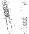
- Fig. 1 shows an example of a device suitable to have the present invention. It shows a delivery device 60, comprising in its proximal part a cartridge housing 66 comprising a cartridge 69.
- the cartridge 69 is intended to be filled with the liquid medicament to be administered to the patient and the delivery device is thus provided with means in order to be connected to a suitable medicament administrating member, such as a needle for the injection of a liquid medicament into the body of the patient, wherein the liquid can have a low as well a high viscosity, but can also be for instance be a mouth or nasal piece, which the patient puts in his mouth or nose, respectively, whereby a metered dose of medicament is inhaled by the patient when the delivery device is set in a medicament delivery state, which will be described in further detail below.
- a suitable medicament administrating member such as a needle for the injection of a liquid medicament into the body of the patient, wherein the liquid can have a low as well a high viscosity, but can also be for instance be a mouth
- the medicament administering member can also be a member that introduces the liquid medicament to the eye of the patient, such as a suitable nozzle that sprays the medicament to the eye, or a member that introduces the medicament to the eye in the form of droplets.
- a nozzle as a medicament administrating member can also be used in order to spray the medicament onto the skin of the patient.
- the delivery device 60 is further in the shown embodiment provided with a needle shield 63, the proximal end of which extends beyond the proximal ends of the cartridge components in order to protect the needle.
- said device may also in its proximal end be provided with removable cap 62.
- the distal end of the needle shield is provided with inward protruding stopper means, the function of which will be described in further detail below.
- the distal part of the delivery device comprises a mechanical dose setting means in the form of a back cover 70 provided with a dose window 72.
- a mechanical indicating member in the form of a hollow dose setting drum 76 arranged.
- the dose setting drum 76 is provided with a through going slot 75 arranged in a helical-formed pattern along the surface of the dose setting drum.
- the back cover is further in its distal part provided with an inward protruding pin (not shown) arranged to engage and run along the slot 75 of the dose setting drum.
- the external surface of the dose setting drum is circunferentially provided with for instance numerical indicators 77 which are visible for the user through a dose window 72, as described further below.
- the window 72 can optionally be provided with a suitable lens or the like, in order to enlarge the dose indicators for the user.
- the interior surface of the back cover is provided with a thread 78 in order to be screw threaded on the proximal part of the device.
- the exterior surface of the proximal part of the device is thus also provided with a thread 79 that is adapted to engage the thread 78.
- the helical-formed configuration of the slot 75 in the dose setting drum 76 consequently corresponds to the pitch of grooving, or screw pitch, of the threads 78, 79.
- the thread 78 is further provided with equally distributed recesses 80, which correspond to at least one protrusion 81 on the exterior of the proximal part of the device.
- An administration drive means in the form of a screw threaded elongated plunger rod 84 is provided in the interior of the delivery device, running along the longitudinal axis of said device.
- the proximal end of the plunger rod is in contact with a piston (not shown) sealingly and slidably provided inside the cartridge 69.
- the plunger rod 84 is provided as a hollow member and the hollow interior of the plunger rod is provided with an energy accumulating member in the form of a helical plunger rod spring 86.
- the distal end of the helical spring 86 is in contact with the inner distal end of the back cover 70 and the proximal end preferably against the inner proximal end surface of the plunger rod 84.
- the plunger rod 84 is further fixedly connected to the dose setting drum 76 by means of inner connecting means 74.
- the plunger rod 84 is adapted to be screwed into the cartridge housing 66 and is further adapted to be housed within a wheel 88 that is provided in the interior of the device 60 distal to the distal end of the cartridge housing.
- the interior part of the cartridge housing 66 that constitutes an entrance for, and is adapted to engage, the plunger rod is thus provided with a thread that has a pitch of grooving, i.e. a screw pitch, that corresponds to thread of the plunger rod.
- the wheel 88 is adapted to be in rotating state and in a non-rotating state and is therefore provided with protruding teeth, which teeth are adapted to engage the stopper means of the needle shield 63. That is, when the delivery device 60 of the third embodiment is in a non-medicament delivery state, a stopper means is provided in between two protruding teeth, holding the wheel in a non-rotating state, as will be described in further detail below.
- the interior of the wheel 88 is further provided with means that corresponds to the thread on the plunger rod, so that when the wheel 88 is in the non-rotating state, the plunger rod is prevented from rotating. Thus, when the wheel 88 is released for rotation, the plunger can be rotated and screwed into the cartridge housing.
- the means in the interior of the wheel 88 is thus also adapted so that the wheel can travel along the longitudinal axis of the plunger rod.
- the interior of the wheel is thus provided with inwardly protruding means 92 that engages longitudinal extending means 91 on the plunger rod.
- the cap 62 is removed from the device 60 and a suitable medicament administrating member is attached to the cartridge retainer, such as a needle. Then the dose is set in a first dose delivery step by rotating the back cover 70 clock-wise.
- the pin will run along the slot 75 of the dose setting drum 76, and the entire back cover will rotate towards the proximal end of the device 60 as the thread 78 is in engagement with the thread 79.
- the recesses 80 of the thread 78 slide over the corresponding protrusions 81.
- the dose is increased by one step and the set dose is visible for the user of the device through the dose window 72 by the numerical indicators provide on the dose setting drum 76. If the dose is set to high, the user can easily rotate the back cover counter-clock wise and adjust the set dose. It is also possible to provide the device with means (not shown) that sets a certain dose as a default dose value, for instance by providing the slot in the dose setting drum with a stopper means at a predetermined position that prevents the pin from running along said slot a longer distance than the distance that correspond to the default dose.
- the plunger rod spring 86 in the interior of the plunger rod 84 is compressed and stepwise accumulates a spring force corresponding to the predetermined distance that the back cover 70 moves towards the proximal end of the device 60.
- the higher dose set the greater spring force accumulated in the spring 86.
- the delivery device 60 is now ready to be set in a medicament delivery state. This is accomplished by pushing the needle shield 63 towards the distal end of the delivery device, preferably by pushing the proximal end of the needle shield 63 against the patient's skin at the medicament delivery site.
- the stopper means 65 of the needle shield come out of engagement with the teeth of the wheel 88, as seen in figure 1a . Due to the accumulated spring force in the plunger rod spring 86 during the first dose delivery step, the plunger rod will now, provided with the force from the spring 86, be screwed into the cartridge housing and moves thus towards the proximal end of the device.
- the proximal end of the plunger rod Since the proximal end of the plunger rod is in contact with the piston sealingly provided inside the cartridge 69, said piston will move a predetermined distance towards the proximal end of the cartridge 69 and deliver the set volume dose.
- the predetermined distance that the piston 87 moves inside the cartridge, and thus the force acting on the piston is determined by the spring force accumulated in the plunger rod spring when the dose is set as well as by the threaded design of the threaded components of the device, i.e. the threads 78 and 79, the thread in the interior of the cartridge housing and the thread on the plunger rod.
- the finer the pitch of grooving, or screw pitch, of the threaded components the higher degree of accuracy will be achieved and the lower the force acting on the piston.
- the device 60 is designed in accordance with the cartridge so that the movement of the piston the predetermined distance towards the proximal end of the cartridge will correspond to the delivery of the dose set in the first dose delivery step.
- the wheel 88 is rotated along with the rotating plunger rod and travels along its longitudinal axis.
- the dose setting drum 76 is rotated and moves along with the downwards rotating plunger rod due to the connecting means 74, whereupon the dose volume to be delivered is visible for the user through the dose window 72 and counts down until the entire dose is delivered. If the cartridge is emptied before the entire dose is delivered, the dose remaining to be taken is shown in the window.
- the back cover will however, stay at its current position and the device thus becomes shorter every time it is used.
- the exterior surface of the proximal part of the device can thus be provided with further dose indicator means (not shown), that by means of the current position of the back cover indicates the remaining doses, i.e. the remaining amount of medicament, in the cartridge.
- Fig. 2 shows a first embodiment of a dose information means arranged to interact with the dose setting means 70 of the described delivery device.
- the rotating dose setting drum 76 with the through-going slot 75 and numerical indicators 77, is in this case longer, i.e. has a hollow cylindrical part 100 attached to the upper end surface of the dose setting drum.
- the cylindrical part 100 is arranged with helical threads 102.
- the back cover 70 is also made longer, Fig. 4 .
- a mechanical dose information means in the embodiment shown a dose information member 104 is arranged, having corresponding threads 106 on its inner surface.
- the dose information member is arranged with indications 108 around its outer surface; such as for example dose quantity.
- the back cover 70 is further arranged with a register information window 110, in which the indications are visible.
- the back cover 70 is rotated clock-wise in a manner described above until the proper, prescribed dose is visible through the dose window 72.
- the prescribed dose could be 10.
- the register information window 110 is in this respect so large that it is possible to insert a finger and to rotate the drum until the corresponding dose indication is shown in that window. It is also conceivable that a second window is arranged on the opposite side of the back cover 70 in order to enhance the rotation of the dose information member.
- the dose information member 104 In order to facilitate the rotation of the dose information member 104 it is preferably arranged with grooves 112 or other grip-enhancing means.
- the rotation of the dose information member causes it to move towards the proximal end of the device due to the threading 102 between the cylindrical part and the dose information member.
- the indications 108 of the dose information member correspond in placing the indications of the dose setting drum 76. As seen in Fig. 2 the dose information member 104 is rotated until the indication "OK" is visible in the register information window 110.
- the dose setting drum 76 When the dose subsequently is delivered, the dose setting drum 76 is rotated as described above until the entire dose is delivered whereby the dose setting drum counts down to zero. Because of the connection with the dose information member 104, it is also rotated, and because of the indications of the dose information member, the proper, prescribed dose is shown in the register information window when the entire dose is delivered, in the shown case "10". Thus, the next time the patient is to set a proper dose, the actual dose to be set is shown in the dose information window. The patient is thus provided with a first indication as to which dose to set, and when rotating the dose setting drum, obtains a second indication that the proper dose is set in that "OK" is shown in the dose information window.
- the dose information member can be arranged with a positive indication, like "OK", a happy face, an arrow pointing towards the front of the device, or any characteristic indication, and for example, arrows on both sides of this positive indication pointing towards this indication.
- a positive indication like "OK"
- a happy face a happy face
- an arrow pointing towards the front of the device or any characteristic indication, and for example, arrows on both sides of this positive indication pointing towards this indication.
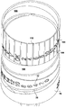
- Fig. 5 shows a second embodiment of a dose information means arranged to interact with the dose setting means 70 of the delivery device.
- the rotating dose setting drum 76 with the through-going slot 75 and numerical indicators 77, has in this case a friction ratchet (not shown) arranged on the upper end inner surface of said dose setting drum 76.
- a dose information member 200 having an equivalent friction ratchet on its lower end outer surface is arranged inside said inner surface.
- said dose information member 200 is also arranged with two slots 201 on its upper end inner surface and wherein said slots 201 comprise sloping edges 202.
- said dose information member 200 is arranged with indications around its outer surface and the back cover 70 is also arranged with a register information window 110, in which the indications are visible.
- the indications can be a positive indication, like "OK”, “SET”, a happy face, an arrow pointing towards the front of the device, or any characteristic indication, and arrows on both sides of this positive indication pointing towards this indication.
- the back cover 70 has been modified at its upper end as shown in Fig 6 .
- the distal end of the back cover is arranged with a wall 71 which extends axially a certain distance; a wall 73 which extends longitudinally a certain distance from the wall 71 towards the proximal end forming a slot 85; and a wall 82 which extends axially a certain distance from the wall 73 forming a closed bulge 83 wherein the distal end of the helical spring 86 is supported.
- said slot 85 between the wall 73 and the inner surface of the back cover 70, the upper end of the dose information member 200, is rotatably arranged.
- said dose information means comprises a locking means 300 arranged to be movable to a released and to an inserted position.
- Said means 300 comprises steel springs 301, locking pins 302 and a release slot 304.
- the wall 71 of the back cover 70 is also arranged with slots wherein the steel springs can be inserted and slidable through sloping edges 89 of the wall 73. Moreover said sloping edges 89 match and have the same inclination of the sloping edges 202 of the dose information member 200.
- the locking means When a certain dose is to be set and this dose is to be "registered” by the dose information member 200, the locking means must be positioned in a released position as shown in Fig. 6 , wherein the steel springs 301 make contact with the slots 201 of the dose information member 200 and with the wall 73 of the back cover 70. Then the back cover 70 is rotated clockwise wherein the dose information member 200 is also rotated with the indication e.g. "OK”, "SET” visible in the register information window 110 until the proper, prescribed dose is visible through the dose window 72.
- the locking means 300 must be positioned in an inserted position through pressing said means 300 towards the proximal end so that the locking pins 302 lock the locking means to the wall 82 of the back cover 70 and the steel springs 301 slides over the sloping edge 202, 89; wherein said steel springs remain supported on the sloping edged 89, see Fig. 7 . Then, the dose information member 200 is free from the back cover 70 and rotates together with dose setting drum 76 when the set and registered dose is delivered.
- the dose setting drum 76 When the dose subsequently is delivered, the dose setting drum 76 is rotated as described above until the entire dose is delivered whereby the dose setting drum counts down to zero. Because of the connection with the dose information member 200, it is also rotated, and because of the indications of the dose information member, the proper, prescribed dose is set the next time the patient is to set the prescribed dose, when the positive indication is shown in the register information window 110.
- the patient/user has the freedom to rotate the dose setting means to a higher or lower dose that the prescribed dose though the indications of the dose information member. Since, after a prescribed dose has been registered, the dose setting means 70 and the dose information member (104; 200) is always rotated to the same amount, the prescribed dose, before each delivery, a third embodiment will be described, wherein the patient will not have the above mentioned freedom.
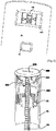
- Fig. 8 shows a third embodiment of a dose information means arranged to interact with the dose setting means 70 of the delivery device.
- the rotating dose setting drum 76 with the through-going slot 75 and numerical indicators 77, has also in this third embodiment a friction ratchet (not shown) arranged on the upper end inner surface of said dose setting drum 76.
- a dose information member 400 having an equivalent friction ratchet on its lower end outer surface is arranged inside said inner surface of said dose setting drum 76 and under its friction ratchet.
- a set of splines is arranged for locking said information member 400 to said dose setting drum 76.
- said dose information member 400 is arranged with indications around its outer surface and the back cover 70 is also arranged with register information window 110, in which the indications are visible.
- the indications can be a positive indication, like "OK”, “SET”, a happy face, an arrow pointing towards the front of the device, or any characteristic indication, and arrows on both sides of this positive indication pointing towards this indication.
- said dose information member 400 comprises at least one pawl (not shown) arranged on the upper end outer surface of the dose information member 400.
- a ratchet (not shown) on the inner surface of the back cover 70 is arranged to interact with the pawl(s) of the dose information member 400.
- said dose information means comprises locking means 500 slidable and switchable arranged on the surface of the back cover 70, as shown in Fig. 8 .
- Said locking means 500 comprises a connecting pin 501 for locking said dose information member 400 to said back cover 70 when said locking means is/are switched. Thereafter, said locking means is/are slidable actuated for unlocking said dose information member 400 from said dose setting drum 76, and for bringing said ratchet on the inner surface of the back cover 70 out of contact with the pawl(s) of the dose information member 400.
- the setting and registration of the prescribed dose can be done through rotating the back cover 70 clockwise wherein the dose information member 400 is also rotated with the indication e.g. "OK", "SET” visible in the register information window 110 until the proper, prescribed dose is visible through the dose window 72.
- said locking means 500 are slidable actuated for locking said dose information member 400 to said dose setting drum 76, and for bringing said ratchet on the inner surface of the back cover 70 in contact with the pawl(s) of the dose information member 400. Thereafter, said locking means 500 is/are switched back for unlocking said dose information member 400 from said back cover 70.
- the dose setting drum 76 When the dose subsequently is delivered, the dose setting drum 76 is rotated until the entire dose is delivered whereby the dose setting drum counts down to zero. Because of the connection with the dose information member 400, it is also rotated, and because of the indications of the dose information member, the proper, prescribed dose is set the next time the patient is to set the prescribed dose, when the positive indication is shown in the register information window 110.
- the dose information member (104; 200; 400) and the dose setting means 70 are each arranged with a protrusion (not shown), wherein said protrusions are arranged for stopping clockwise rotation of the dose setting means 70, during the setting of the registered dose.
- the present invention may be modified in a number of ways in order to arrive at the present invention.
- the dose information wheel may be connected to the dose setting wheel in other ways to perform the desired function.
Landscapes
- Health & Medical Sciences (AREA)
- Engineering & Computer Science (AREA)
- Life Sciences & Earth Sciences (AREA)
- Public Health (AREA)
- Anesthesiology (AREA)
- Biomedical Technology (AREA)
- Heart & Thoracic Surgery (AREA)
- Hematology (AREA)
- Animal Behavior & Ethology (AREA)
- General Health & Medical Sciences (AREA)
- Veterinary Medicine (AREA)
- Bioinformatics & Cheminformatics (AREA)
- Pulmonology (AREA)
- Biophysics (AREA)
- Vascular Medicine (AREA)
- Infusion, Injection, And Reservoir Apparatuses (AREA)
Description
- The present invention relates to a dose information device to be used with a medical delivery device such as an injector, an inhaler or the like.
- There is a large market for a variety of devices for self-administration of medicament and it is growing steadily, mainly because it is cheaper and also more convenient for the patients to handle the administration of medicament themselves instead of having to visit a medical clinic or a doctor in order to have the medicament administered.
- Within the field of devices for self-administration there is a variety of devices intended and designed for different types of medicament and different ways of administration, such as inhalers for powder or aerosol driven medicament, nebulizers capable of producing spray of medicament with very fine droplets, injectors for injecting medicament in the body of a patient.
- Many of the devices are designed to be able to administer several doses before the device is discarded or needs to be refilled and/or designed to be able to administer doses of medicament that are of different sizes. In the latter case, the device is arranged with some sort of movable part that the patient uses in order to set the correct dose prescribed by the physician. The set dose is often displayed as a digit in a window or for example on a rotatable sleeve of knob, having corresponding indexing means on a fixed part indicating the set dose.
- In order to ascertain that the set dose cannot exceed a prescribed dose, a few devices have been developed.
- One example of such a device is disclosed in patent application no.
WO 99/64092 - The patent application no.
WO 01/54757 US 5947934 . - Even though these devices function as to limit the risk of setting a too large dose, they have the drawback of being difficult to handle if other dose quantities are to be set and/or including parts that are either rather bulky or not user-friendly.
- The aim of the present invention is to provide a dose information device that indicates when the prescribed dose is set before administration of the medicament.
- This aim is solved by a device according to independent claim 1. Preferable embodiments are subject of the dependent claims.
- According to a main aspect of the invention it is characterized by a device to be used with a medical administration device, which administration device comprises administration drive means for administrating a prescribed dose of medicament; mechanical dose setting means for setting a prescribed dose of medicament to be administered, including a mechanical indicating member (76) fixedly connected to said administration drive means (84) for indicating the prescribed set dose, wherein said device comprises mechanical dose information means for registering the prescribed dose of medicament to be administered including a mechanical information member adjustable to display that said prescribed dose to be administered is correct, and inter-connected to said mechanical indicating member such that when the prescribed dose is set, this is indicated positively by indications on said mechanical information member.
- According to the invention it is characterised in that said dose setting means is arranged to rotate, during the setting of the prescribed dose, until the prescribed dose is visible in a dose window and said dose information member is arranged to rotate, during the registration of the prescribed dose, until a positive indication is visible in a register information window.
- Yet, according to another aspect of the invention it is characterised in that said mechanical dose information means comprises a locking means for locking said dose information member to said dose setting means, before and under the setting and registration of the prescribed dose and for unlocking said dose information member from said dose setting means, after the setting and registration of the prescribed dose. Text to be inserted between paragraphs 0007 and 0008 of the description as originally published by the International Bureau.
- Patent application No.
WO 97/36626 - Patent application No.
WO 03/057285 WO 97/36626 - Further, according to another aspect of the invention it is characterised in that the dose setting means is arranged with a ratchet and a protrusion arranged to interact with pawl(s) and a protrusion respectively, arranged on said dose information member, for stopping counter-clockwise rotation of the dose setting means during the setting of the registered dose; and for stopping clockwise rotation of the dose setting means after the setting of the registered dose.
- Yet, according to another aspect of the invention it is characterised in that said mechanical indicating member is arranged to rotate, during administration of medicament, from a position where the correct prescribed dose is visible, to a position where it is indicated that the correct dose is given, and that said dose information member during administration of medicament, rotates from a position where it is indicated positively that the correct prescribed dose is set, to a position indicating the dose to be set for the subsequent dose delivery.
- The benefits of the present invention are several. With the use of a dose information means, it is possible for the user to indicate once the proper prescribed dose to be delivered, which is done the first time the medical administration device is used. For any subsequent dose, because of the inter-connection between the dose setting member and the dose information means, when rotating the dose setting means, the dose information member will indicate positively when the correct prescribed dose is set. The user thus does not have to remember the correct dose for further dose deliveries, because this is indicated by the dose information means.
- The dose information member could either display or indicate the actual dose quantity when the dose is to be set, and give a positive indication when this dose is reached by the dose setting means, or could indicate, for example when the dose setting means is rotatable to set the required dose, that the dose setting means should be rotated in either direction for reaching the proper prescribed dose.
- Preferably the dose information member is a drum inter-connected with the dose setting means, which in turn could be a part of the housing of the medicament delivery device, and connected to for example a plunger rod movable inside the housing during delivery. The movement of the plunger rod thus affects and rotates the dose setting indications as well as the dose information.
- The present invention could be used with a number of medical delivery devices that are capable of providing a number of different set doses.
- These and other aspects of and advantages with the present invention will become apparent from the following detailed description and from the accompanying drawings.
- In the following detailed description of the invention, reference will be made to the accompanying drawings of which,
-
figs. 1a and b show views partially in cross-section of a medical device intended to comprise a device according to the present invention, -
Fig. 2 shows a detailed view of a component of the device according to a first embodiment of the present invention,Fig. 3 shows another view of the component ofFig. 2 , and -
Fig. 4 shows a detailed view of a medical device comprising the present invention. -
Fig. 5 shows the device according to a second embodiment of the present invention, partly in cross-section having a locking means, -
Fig. 6 shows a detailed view of the locking means ofFig. 5 when said locking means is in a released position, -
Fig. 7 shows a detailed view of the locking means ofFig. 5 when said locking means is in an inserted position, and -
Fig. 8 shows the device according to a third embodiment of the present invention, partly in cross-section having a locking means. - The present invention is intended to be arranged in a medical administering device such as an inhaler or an injector.
-
Fig. 1 shows an example of a device suitable to have the present invention. It shows adelivery device 60, comprising in its proximal part acartridge housing 66 comprising acartridge 69. Thecartridge 69 is intended to be filled with the liquid medicament to be administered to the patient and the delivery device is thus provided with means in order to be connected to a suitable medicament administrating member, such as a needle for the injection of a liquid medicament into the body of the patient, wherein the liquid can have a low as well a high viscosity, but can also be for instance be a mouth or nasal piece, which the patient puts in his mouth or nose, respectively, whereby a metered dose of medicament is inhaled by the patient when the delivery device is set in a medicament delivery state, which will be described in further detail below. The medicament administering member can also be a member that introduces the liquid medicament to the eye of the patient, such as a suitable nozzle that sprays the medicament to the eye, or a member that introduces the medicament to the eye in the form of droplets. Naturally, a nozzle as a medicament administrating member can also be used in order to spray the medicament onto the skin of the patient. - The
delivery device 60 is further in the shown embodiment provided with aneedle shield 63, the proximal end of which extends beyond the proximal ends of the cartridge components in order to protect the needle. For further protection of the delivery device, said device may also in its proximal end be provided withremovable cap 62. The distal end of the needle shield is provided with inward protruding stopper means, the function of which will be described in further detail below. - The distal part of the delivery device comprises a mechanical dose setting means in the form of a
back cover 70 provided with adose window 72. In the interior distal part of the back cover is a mechanical indicating member in the form of a hollowdose setting drum 76 arranged. Thedose setting drum 76 is provided with a through goingslot 75 arranged in a helical-formed pattern along the surface of the dose setting drum. The back cover is further in its distal part provided with an inward protruding pin (not shown) arranged to engage and run along theslot 75 of the dose setting drum. Moreover, the external surface of the dose setting drum is circunferentially provided with for instancenumerical indicators 77 which are visible for the user through adose window 72, as described further below. Thewindow 72 can optionally be provided with a suitable lens or the like, in order to enlarge the dose indicators for the user. - The interior surface of the back cover is provided with a
thread 78 in order to be screw threaded on the proximal part of the device. The exterior surface of the proximal part of the device is thus also provided with athread 79 that is adapted to engage thethread 78. The helical-formed configuration of theslot 75 in thedose setting drum 76 consequently corresponds to the pitch of grooving, or screw pitch, of thethreads thread 78 is further provided with equally distributed recesses 80, which correspond to at least one protrusion 81 on the exterior of the proximal part of the device. - An administration drive means in the form of a screw threaded
elongated plunger rod 84 is provided in the interior of the delivery device, running along the longitudinal axis of said device. The proximal end of the plunger rod is in contact with a piston (not shown) sealingly and slidably provided inside thecartridge 69. Theplunger rod 84 is provided as a hollow member and the hollow interior of the plunger rod is provided with an energy accumulating member in the form of a helical plunger rod spring 86. The distal end of the helical spring 86 is in contact with the inner distal end of theback cover 70 and the proximal end preferably against the inner proximal end surface of theplunger rod 84. Theplunger rod 84 is further fixedly connected to thedose setting drum 76 by means of inner connectingmeans 74. - The
plunger rod 84 is adapted to be screwed into thecartridge housing 66 and is further adapted to be housed within a wheel 88 that is provided in the interior of thedevice 60 distal to the distal end of the cartridge housing. The interior part of thecartridge housing 66 that constitutes an entrance for, and is adapted to engage, the plunger rod is thus provided with a thread that has a pitch of grooving, i.e. a screw pitch, that corresponds to thread of the plunger rod. Thethreads slot 75, all have the same predetermined pitch of grooving, or screw pitch. The wheel 88 is adapted to be in rotating state and in a non-rotating state and is therefore provided with protruding teeth, which teeth are adapted to engage the stopper means of theneedle shield 63. That is, when thedelivery device 60 of the third embodiment is in a non-medicament delivery state, a stopper means is provided in between two protruding teeth, holding the wheel in a non-rotating state, as will be described in further detail below. The interior of the wheel 88 is further provided with means that corresponds to the thread on the plunger rod, so that when the wheel 88 is in the non-rotating state, the plunger rod is prevented from rotating. Thus, when the wheel 88 is released for rotation, the plunger can be rotated and screwed into the cartridge housing. The means in the interior of the wheel 88, is thus also adapted so that the wheel can travel along the longitudinal axis of the plunger rod. The interior of the wheel is thus provided with inwardly protruding means 92 that engages longitudinal extending means 91 on the plunger rod. - Before use, the
cap 62 is removed from thedevice 60 and a suitable medicament administrating member is attached to the cartridge retainer, such as a needle. Then the dose is set in a first dose delivery step by rotating theback cover 70 clock-wise. When rotating the back-cover, the pin will run along theslot 75 of thedose setting drum 76, and the entire back cover will rotate towards the proximal end of thedevice 60 as thethread 78 is in engagement with thethread 79. As theback cover 70 moves towards the proximal end of the device, the recesses 80 of thethread 78 slide over the corresponding protrusions 81. Each time a recess 80 slides over such a corresponding protrusion 81, the dose is increased by one step and the set dose is visible for the user of the device through thedose window 72 by the numerical indicators provide on thedose setting drum 76. If the dose is set to high, the user can easily rotate the back cover counter-clock wise and adjust the set dose. It is also possible to provide the device with means (not shown) that sets a certain dose as a default dose value, for instance by providing the slot in the dose setting drum with a stopper means at a predetermined position that prevents the pin from running along said slot a longer distance than the distance that correspond to the default dose. - As the back cover moves in steps towards the proximal end of the
device 60, also the plunger rod spring 86 in the interior of theplunger rod 84 is compressed and stepwise accumulates a spring force corresponding to the predetermined distance that theback cover 70 moves towards the proximal end of thedevice 60. The higher dose set, the greater spring force accumulated in the spring 86. - The
delivery device 60 is now ready to be set in a medicament delivery state. This is accomplished by pushing theneedle shield 63 towards the distal end of the delivery device, preferably by pushing the proximal end of theneedle shield 63 against the patient's skin at the medicament delivery site. When the needle shield moves towards the distal end of the delivery device, the stopper means 65 of the needle shield come out of engagement with the teeth of the wheel 88, as seen infigure 1a . Due to the accumulated spring force in the plunger rod spring 86 during the first dose delivery step, the plunger rod will now, provided with the force from the spring 86, be screwed into the cartridge housing and moves thus towards the proximal end of the device. Since the proximal end of the plunger rod is in contact with the piston sealingly provided inside thecartridge 69, said piston will move a predetermined distance towards the proximal end of thecartridge 69 and deliver the set volume dose. The predetermined distance that the piston 87 moves inside the cartridge, and thus the force acting on the piston, is determined by the spring force accumulated in the plunger rod spring when the dose is set as well as by the threaded design of the threaded components of the device, i.e. thethreads device 60 is designed in accordance with the cartridge so that the movement of the piston the predetermined distance towards the proximal end of the cartridge will correspond to the delivery of the dose set in the first dose delivery step. - During dose delivery, when the
plunger rod 84 is forced into the cartridge housing, the wheel 88 is rotated along with the rotating plunger rod and travels along its longitudinal axis. Thedose setting drum 76 is rotated and moves along with the downwards rotating plunger rod due to the connectingmeans 74, whereupon the dose volume to be delivered is visible for the user through thedose window 72 and counts down until the entire dose is delivered. If the cartridge is emptied before the entire dose is delivered, the dose remaining to be taken is shown in the window. The back cover will however, stay at its current position and the device thus becomes shorter every time it is used. The exterior surface of the proximal part of the device, can thus be provided with further dose indicator means (not shown), that by means of the current position of the back cover indicates the remaining doses, i.e. the remaining amount of medicament, in the cartridge. - According to the present invention,
Fig. 2 shows a first embodiment of a dose information means arranged to interact with the dose setting means 70 of the described delivery device. The rotatingdose setting drum 76, with the through-goingslot 75 andnumerical indicators 77, is in this case longer, i.e. has a hollowcylindrical part 100 attached to the upper end surface of the dose setting drum. Thecylindrical part 100 is arranged withhelical threads 102. In order to accommodate the cylindrical part, theback cover 70 is also made longer,Fig. 4 . Around the cylindrical part a mechanical dose information means, in the embodiment shown adose information member 104 is arranged, havingcorresponding threads 106 on its inner surface. The dose information member is arranged withindications 108 around its outer surface; such as for example dose quantity. Theback cover 70 is further arranged with aregister information window 110, in which the indications are visible. - When a certain dose is to be set and this dose is to be "registered" by the
dose information member 104, theback cover 70 is rotated clock-wise in a manner described above until the proper, prescribed dose is visible through thedose window 72. As seen inFig. 2 , as an example, the prescribed dose could be 10. Now the proper, prescribed dose is to be registered by thedose information member 104. Theregister information window 110 is in this respect so large that it is possible to insert a finger and to rotate the drum until the corresponding dose indication is shown in that window. It is also conceivable that a second window is arranged on the opposite side of theback cover 70 in order to enhance the rotation of the dose information member. - In order to facilitate the rotation of the
dose information member 104 it is preferably arranged withgrooves 112 or other grip-enhancing means. The rotation of the dose information member causes it to move towards the proximal end of the device due to the threading 102 between the cylindrical part and the dose information member. Theindications 108 of the dose information member correspond in placing the indications of thedose setting drum 76. As seen inFig. 2 thedose information member 104 is rotated until the indication "OK" is visible in theregister information window 110. - When the dose subsequently is delivered, the
dose setting drum 76 is rotated as described above until the entire dose is delivered whereby the dose setting drum counts down to zero. Because of the connection with thedose information member 104, it is also rotated, and because of the indications of the dose information member, the proper, prescribed dose is shown in the register information window when the entire dose is delivered, in the shown case "10". Thus, the next time the patient is to set a proper dose, the actual dose to be set is shown in the dose information window. The patient is thus provided with a first indication as to which dose to set, and when rotating the dose setting drum, obtains a second indication that the proper dose is set in that "OK" is shown in the dose information window. - Instead of having dose quantities displayed in the dose information window, the dose information member can be arranged with a positive indication, like "OK", a happy face, an arrow pointing towards the front of the device, or any characteristic indication, and for example, arrows on both sides of this positive indication pointing towards this indication. This will show the user, when setting a dose, in which direction he or she has to rotate the back cover in order to arrive at the proper dose.
- According to the present invention,
Fig. 5 shows a second embodiment of a dose information means arranged to interact with the dose setting means 70 of the delivery device. The rotatingdose setting drum 76, with the through-goingslot 75 andnumerical indicators 77, has in this case a friction ratchet (not shown) arranged on the upper end inner surface of saiddose setting drum 76. Inside said inner surface, adose information member 200 having an equivalent friction ratchet on its lower end outer surface is arranged. As seen inFig. 6 , saiddose information member 200 is also arranged with twoslots 201 on its upper end inner surface and wherein saidslots 201 comprise slopingedges 202. Further, saiddose information member 200 is arranged with indications around its outer surface and theback cover 70 is also arranged with aregister information window 110, in which the indications are visible. The indications can be a positive indication, like "OK", "SET", a happy face, an arrow pointing towards the front of the device, or any characteristic indication, and arrows on both sides of this positive indication pointing towards this indication. - In this second embodiment, the
back cover 70 has been modified at its upper end as shown inFig 6 . The distal end of the back cover is arranged with awall 71 which extends axially a certain distance; awall 73 which extends longitudinally a certain distance from thewall 71 towards the proximal end forming aslot 85; and awall 82 which extends axially a certain distance from thewall 73 forming aclosed bulge 83 wherein the distal end of the helical spring 86 is supported. In saidslot 85, between thewall 73 and the inner surface of theback cover 70, the upper end of thedose information member 200, is rotatably arranged. - In order to facilitate the rotation of the
dose information member 200 under the setting and registration of the prescribed dose, said dose information means comprises a locking means 300 arranged to be movable to a released and to an inserted position. Said means 300 comprises steel springs 301, lockingpins 302 and arelease slot 304. For this purpose, thewall 71 of theback cover 70 is also arranged with slots wherein the steel springs can be inserted and slidable through slopingedges 89 of thewall 73. Moreover said slopingedges 89 match and have the same inclination of thesloping edges 202 of thedose information member 200. - When a certain dose is to be set and this dose is to be "registered" by the
dose information member 200, the locking means must be positioned in a released position as shown inFig. 6 , wherein the steel springs 301 make contact with theslots 201 of thedose information member 200 and with thewall 73 of theback cover 70. Then theback cover 70 is rotated clockwise wherein thedose information member 200 is also rotated with the indication e.g. "OK", "SET" visible in theregister information window 110 until the proper, prescribed dose is visible through thedose window 72. Now, the locking means 300 must be positioned in an inserted position through pressing said means 300 towards the proximal end so that the locking pins 302 lock the locking means to thewall 82 of theback cover 70 and the steel springs 301 slides over thesloping edge Fig. 7 . Then, thedose information member 200 is free from theback cover 70 and rotates together withdose setting drum 76 when the set and registered dose is delivered. - When the dose subsequently is delivered, the
dose setting drum 76 is rotated as described above until the entire dose is delivered whereby the dose setting drum counts down to zero. Because of the connection with thedose information member 200, it is also rotated, and because of the indications of the dose information member, the proper, prescribed dose is set the next time the patient is to set the prescribed dose, when the positive indication is shown in theregister information window 110. - Heretofore, with the above mentioned embodiments, after a prescribed dose has been registered, the patient/user has the freedom to rotate the dose setting means to a higher or lower dose that the prescribed dose though the indications of the dose information member. Since, after a prescribed dose has been registered, the dose setting means 70 and the dose information member (104; 200) is always rotated to the same amount, the prescribed dose, before each delivery, a third embodiment will be described, wherein the patient will not have the above mentioned freedom.
- According to the present invention,
Fig. 8 shows a third embodiment of a dose information means arranged to interact with the dose setting means 70 of the delivery device. The rotatingdose setting drum 76, with the through-goingslot 75 andnumerical indicators 77, has also in this third embodiment a friction ratchet (not shown) arranged on the upper end inner surface of saiddose setting drum 76. Inside said inner surface, adose information member 400 having an equivalent friction ratchet on its lower end outer surface is arranged. Moreover, inside the inner surface of saiddose setting drum 76 and under its friction ratchet, a set of splines is arranged for locking saidinformation member 400 to saiddose setting drum 76. Further, saiddose information member 400 is arranged with indications around its outer surface and theback cover 70 is also arranged withregister information window 110, in which the indications are visible. The indications can be a positive indication, like "OK", "SET", a happy face, an arrow pointing towards the front of the device, or any characteristic indication, and arrows on both sides of this positive indication pointing towards this indication. Moreover, saiddose information member 400 comprises at least one pawl (not shown) arranged on the upper end outer surface of thedose information member 400. - In this third embodiment, a ratchet (not shown) on the inner surface of the
back cover 70 is arranged to interact with the pawl(s) of thedose information member 400. - In order to facilitate the rotation of the
dose information member 400 under the setting and registration of the prescribed dose, said dose information means comprises locking means 500 slidable and switchable arranged on the surface of theback cover 70, as shown inFig. 8 . Said locking means 500 comprises a connectingpin 501 for locking saiddose information member 400 to saidback cover 70 when said locking means is/are switched. Thereafter, said locking means is/are slidable actuated for unlocking saiddose information member 400 from saiddose setting drum 76, and for bringing said ratchet on the inner surface of theback cover 70 out of contact with the pawl(s) of thedose information member 400. Then, the setting and registration of the prescribed dose can be done through rotating theback cover 70 clockwise wherein thedose information member 400 is also rotated with the indication e.g. "OK", "SET" visible in theregister information window 110 until the proper, prescribed dose is visible through thedose window 72. - After the setting and registration of the prescribed dose, said locking means 500 are slidable actuated for locking said
dose information member 400 to saiddose setting drum 76, and for bringing said ratchet on the inner surface of theback cover 70 in contact with the pawl(s) of thedose information member 400. Thereafter, said locking means 500 is/are switched back for unlocking saiddose information member 400 from saidback cover 70. - When the dose subsequently is delivered, the
dose setting drum 76 is rotated until the entire dose is delivered whereby the dose setting drum counts down to zero. Because of the connection with thedose information member 400, it is also rotated, and because of the indications of the dose information member, the proper, prescribed dose is set the next time the patient is to set the prescribed dose, when the positive indication is shown in theregister information window 110. - The dose information member (104; 200; 400) and the dose setting means 70 are each arranged with a protrusion (not shown), wherein said protrusions are arranged for stopping clockwise rotation of the dose setting means 70, during the setting of the registered dose.
- Thus, with this third embodiment, when the patient/user intend to set the registered prescribed dose again, he/she needs only to rotate the dose setting means 70 clockwise until it stops and the positive indication is also shown in the
register information window 110. The patient/user cannot rotate the dose setting means 70 counter-clockwise due to the design of ratchet on the inner surface of theback cover 70 and the pawl(s) of thedose information member 400. - It is to be understood that the present invention may be modified in a number of ways in order to arrive at the present invention. For example the dose information wheel may be connected to the dose setting wheel in other ways to perform the desired function.
Claims (8)
- Device to be used with a medical administration device, which administration device comprises a threaded plunger rod (84) for administrating a prescribed dose of medicament; mechanical dose setting means (70) in the form of a back cover for setting a prescribed dose of medicament to be administered, said device comprising mechanical dose information means for registering the prescribed dose of medicament to be administered including a mechanical dose information member (104; 200; 400) movably inter-connected to a mechanical indicating member (76) in the form of a dose drum and adjustable to display that said prescribed dose to be administered is correct, including a plurality of indications (108) for registering the prescribed set dose such that when the prescribed dose is set, this is indicated by a positive indication (108) on said mechanical dose information member (104; 200; 400), that said back cover (70) comprises a dose window (72) and a register information window (110), characterised in that said dose drum is fixedly connected to said threaded plunger rod (84) for indicating the set dose, that said back cover (70) is arranged rotatable relative said dose drum (76), during the setting of the prescribed dose, until the prescribed dose is visible in the dose window (72) and said dose information member (104) is rotatable relative said back cover (70) and said dose drum (76), during the registration of the prescribed dose, until a positive indication is visible in the register information window (110).
- Device according to claim 1 characterised in that said dose information member (104) is arranged with grooves (112) or other grip-enhancing means for registering the set prescribed dose after the setting of the prescribed dose.
- Device according to any one of the claims 1 or 2, characterised in that said mechanical dose information means comprises a locking means (300; 500) for locking said dose information member (200; 400) to said dose setting means (70), before and under the setting and registration of the prescribed dose and for unlocking said dose information member (200; 400) from said dose setting means (70), after the setting and registration of the prescribed dose.
- Device according to claim 3, characterised in that said locking means (500) is arranged to be swithchable and slidable on the surface of the dose setting means (70) for locking said dose information member (400) to said dose drum (76), after the setting and registration of the prescribed dose and for unlocking said dose information member (400) from said dose drum (76), before the setting and registration of the prescribed dose.
- Device according to claim 4, characterised in that a ratchet on the inner surface of the back cover (70) is arranged to be in contact with at least one pawl on the outer surface of the dose information member (400) when said dose information member (400) is locked to the dose drum (76) and is arranged to be out of contact from said pawl/s when said dose information member (400) is unlocked from the dose drum (76).
- Device according to claim 5, characterised in that said ratchet on the inner surface of the back cover (70) and said pawl/s on the outer surface of the dose information member (400) are arranged to interact for stopping counter-clockwise rotation of the back cover (70), during the setting of the registered dose.
- Device according to any one of the preceding claims characterised in that said dose information member (104; 200; 400) and said back cover (70) are each arranged with a protrusion, wherein said protrusions are arranged for stopping clockwise rotation of the back cover (70), during the setting of the registered dose.
- Device according to any one of the preceding claims characterised in that said dose drum (76) is arranged to rotate, during administration of medicament, from a position where the correct prescribed dose is visible, to a position where it is indicated that the correct dose is given, and that said dose information member (104; 200; 400) during administration of medicament, rotates from a position where it is indicated positively that the correct prescribed dose is set, to a position indicating the dose to be set for the subsequent dose delivery.
Applications Claiming Priority (2)
| Application Number | Priority Date | Filing Date | Title |
|---|---|---|---|
| US74360406P | 2006-03-21 | 2006-03-21 | |
| PCT/EP2007/051781 WO2007107431A1 (en) | 2006-03-21 | 2007-02-26 | Dose information device |
Publications (2)
| Publication Number | Publication Date |
|---|---|
| EP2007451A1 EP2007451A1 (en) | 2008-12-31 |
| EP2007451B1 true EP2007451B1 (en) | 2018-11-07 |
Family
ID=38002056
Family Applications (1)
| Application Number | Title | Priority Date | Filing Date |
|---|---|---|---|
| EP07712318.0A Not-in-force EP2007451B1 (en) | 2006-03-21 | 2007-02-26 | Dose information device |
Country Status (3)
| Country | Link |
|---|---|
| US (1) | US8875700B2 (en) |
| EP (1) | EP2007451B1 (en) |
| WO (1) | WO2007107431A1 (en) |
Cited By (1)
| Publication number | Priority date | Publication date | Assignee | Title |
|---|---|---|---|---|
| EP2983771B1 (en) | 2013-04-10 | 2020-12-02 | Sanofi | Drive mechanism for a drug delivery device |
Families Citing this family (43)
| Publication number | Priority date | Publication date | Assignee | Title |
|---|---|---|---|---|
| GB0425518D0 (en) | 2004-11-19 | 2004-12-22 | Clinical Designs Ltd | Substance source |
| GB0428204D0 (en) | 2004-12-23 | 2005-01-26 | Clinical Designs Ltd | Medicament container |
| DE602006004314D1 (en) | 2005-02-28 | 2009-01-29 | Novo Nordisk As | DOSE SETTING MECHANISM FOR AN INJECTION DEVICE WHICH CAN PRESCRIBE A HIGHEST DOSE |
| GB0518400D0 (en) | 2005-09-09 | 2005-10-19 | Clinical Designs Ltd | Dispenser |
| EP2060289A1 (en) * | 2007-11-13 | 2009-05-20 | F.Hoffmann-La Roche Ag | Administration device comprising indication unit and method for setting a dose |
| EP2077132A1 (en) | 2008-01-02 | 2009-07-08 | Boehringer Ingelheim Pharma GmbH & Co. KG | Dispensing device, storage device and method for dispensing a formulation |
| US20100286633A1 (en) * | 2008-02-05 | 2010-11-11 | Marx Alvin J | Precision Lid Retracting Eyedropper Device |
| US8246589B2 (en) * | 2008-02-05 | 2012-08-21 | Marx Alvin J | Precision lid retracting eyedropper device |
| US8734408B2 (en) | 2008-02-05 | 2014-05-27 | Alvin J. Marx | Automated eyedrop delivery system with eyelid retracting legs |
| TR201807257T4 (en) * | 2009-02-26 | 2018-06-21 | Shl Group Ab | Dose adjustment mechanisms. |
| GB0904040D0 (en) | 2009-03-10 | 2009-04-22 | Euro Celtique Sa | Counter |
| GB0904059D0 (en) * | 2009-03-10 | 2009-04-22 | Euro Celtique Sa | Counter |
| EP2414560B1 (en) | 2009-03-31 | 2013-10-23 | Boehringer Ingelheim International GmbH | Method for coating a surface of a component |
| WO2010133294A2 (en) | 2009-05-18 | 2010-11-25 | Boehringer Ingelheim International Gmbh | Adapter, inhalation device, and atomizer |
| WO2010140974A1 (en) * | 2009-06-05 | 2010-12-09 | Shl Group Ab | Medicament delivery device |
| WO2011039219A2 (en) * | 2009-09-30 | 2011-04-07 | Sanofi-Aventis Deutschland Gmbh | Drug delivery device, assembly for a drug delivery device and method for setting up a drug delivery device |
| GB0918145D0 (en) | 2009-10-16 | 2009-12-02 | Owen Mumford Ltd | Injector apparatus |
| CN102740910B (en) * | 2009-11-20 | 2014-07-30 | 贝克顿·迪金森公司 | Injection device without a gearing |
| WO2011064164A1 (en) | 2009-11-25 | 2011-06-03 | Boehringer Ingelheim International Gmbh | Nebulizer |
| EP2504051B1 (en) | 2009-11-25 | 2019-09-04 | Boehringer Ingelheim International GmbH | Nebulizer |
| US10016568B2 (en) | 2009-11-25 | 2018-07-10 | Boehringer Ingelheim International Gmbh | Nebulizer |
| US9943654B2 (en) | 2010-06-24 | 2018-04-17 | Boehringer Ingelheim International Gmbh | Nebulizer |
| WO2012130757A1 (en) | 2011-04-01 | 2012-10-04 | Boehringer Ingelheim International Gmbh | Medical device comprising a container |
| EP2709697B1 (en) * | 2011-05-19 | 2019-03-06 | Becton, Dickinson and Company | Injection device with plural dosage setting windows |
| US9827384B2 (en) | 2011-05-23 | 2017-11-28 | Boehringer Ingelheim International Gmbh | Nebulizer |
| IN2014DN08681A (en) | 2012-04-13 | 2015-05-22 | Becton Dickinson Co | |
| WO2013152894A1 (en) | 2012-04-13 | 2013-10-17 | Boehringer Ingelheim International Gmbh | Atomiser with coding means |
| TWI599377B (en) * | 2013-01-15 | 2017-09-21 | 卡貝歐洲有限公司 | Medicament delivery device |
| TW201440825A (en) * | 2013-01-15 | 2014-11-01 | Carebay Europe Ltd | Medicament delivery device |
| WO2015018904A1 (en) | 2013-08-09 | 2015-02-12 | Boehringer Ingelheim International Gmbh | Nebulizer |
| EP2835146B1 (en) * | 2013-08-09 | 2020-09-30 | Boehringer Ingelheim International GmbH | Nebulizer |
| CN105530970B (en) * | 2013-09-10 | 2021-04-06 | 赛诺菲 | Dose indicating mechanism for a drug delivery device |
| EP3077024B1 (en) | 2013-12-05 | 2018-01-31 | Novo Nordisk A/S | A housing for a medical injection device |
| US10195374B2 (en) | 2014-05-07 | 2019-02-05 | Boehringer Ingelheim International Gmbh | Container, nebulizer and use |
| US10722666B2 (en) | 2014-05-07 | 2020-07-28 | Boehringer Ingelheim International Gmbh | Nebulizer with axially movable and lockable container and indicator |
| CN106232166B (en) | 2014-05-07 | 2020-04-14 | 勃林格殷格翰国际有限公司 | Sprayer with a spray tube |
| JP6703492B2 (en) | 2014-05-28 | 2020-06-03 | サノフィ−アベンティス・ドイチュラント・ゲゼルシャフト・ミット・ベシュレンクテル・ハフツング | Dose marking mechanism and drug delivery device for drug delivery device |
| JP6559163B2 (en) | 2014-06-26 | 2019-08-14 | ノボ・ノルデイスク・エー/エス | Pen-type torsion spring driven injection device |
| TW201632214A (en) * | 2014-10-09 | 2016-09-16 | 賽諾菲公司 | Method for assembling a drive spring and drug delivery device with a spring |
| EP3058974A1 (en) | 2015-02-19 | 2016-08-24 | Sanofi-Aventis Deutschland GmbH | Injection device with supplementary device |
| WO2016150900A2 (en) | 2015-03-23 | 2016-09-29 | Sanofi-Aventis Deutschland Gmbh | Injection device |
| JP6829694B2 (en) | 2015-06-01 | 2021-02-10 | ノボ・ノルデイスク・エー/エス | Housing for medical injection devices |
| EP3487563B1 (en) * | 2016-07-21 | 2022-03-23 | Philip Morris Products S.A. | Dry powder inhaler |
Family Cites Families (15)
| Publication number | Priority date | Publication date | Assignee | Title |
|---|---|---|---|---|
| GB2109690B (en) * | 1981-02-12 | 1985-02-20 | Robert Charles Turner | Dose metering plunger devices for use with syringes |
| US5582598A (en) * | 1994-09-19 | 1996-12-10 | Becton Dickinson And Company | Medication delivery pen with variable increment dose scale |
| US5697916A (en) * | 1995-11-21 | 1997-12-16 | Stat Medical Devices Inc. | Hypodermic dosage measuring device |
| DE59609513D1 (en) * | 1996-04-02 | 2002-09-05 | Disetronic Licensing Ag | INJECTION DEVICE |
| US5947934A (en) * | 1996-09-13 | 1999-09-07 | Novo Nordisk A/S | Dose display for an injection syringe |
| US6074372A (en) * | 1997-06-09 | 2000-06-13 | Novo Nordisk A/S | Dose setting mechanism and an injection syringe having such a dose setting mechanism |
| JP2001509426A (en) * | 1997-07-11 | 2001-07-24 | ノボ ノルディスク アクティーゼルスカブ | Equipment for display of medical equipment settings |
| GB9812472D0 (en) * | 1998-06-11 | 1998-08-05 | Owen Mumford Ltd | A dose setting device for medical injectors |
| TW453884B (en) * | 1999-09-16 | 2001-09-11 | Novo Nordisk As | Dose setting limiter |
| GB2375965B (en) | 2000-01-28 | 2004-09-01 | Novo Nordisk As | A dose setting limiter |
| US6663602B2 (en) * | 2000-06-16 | 2003-12-16 | Novo Nordisk A/S | Injection device |
| GB0200444D0 (en) * | 2002-01-10 | 2002-02-27 | Owen Mumford Ltd | Improvements relating to medical injection devices |
| US6945961B2 (en) * | 2002-07-10 | 2005-09-20 | Novo Nordisk A/S | Injection device |
| DE10239784B4 (en) * | 2002-08-29 | 2004-12-30 | Tecpharma Licensing Ag | Injection, infusion or inhalation device with dose display device |
| WO2005072794A2 (en) * | 2004-01-29 | 2005-08-11 | M 2 Medical A/S | Disposable medicine dispensing device |
-
2007
- 2007-02-26 WO PCT/EP2007/051781 patent/WO2007107431A1/en active Application Filing
- 2007-02-26 EP EP07712318.0A patent/EP2007451B1/en not_active Not-in-force
- 2007-02-26 US US12/293,518 patent/US8875700B2/en active Active
Non-Patent Citations (1)
| Title |
|---|
| None * |
Cited By (1)
| Publication number | Priority date | Publication date | Assignee | Title |
|---|---|---|---|---|
| EP2983771B1 (en) | 2013-04-10 | 2020-12-02 | Sanofi | Drive mechanism for a drug delivery device |
Also Published As
| Publication number | Publication date |
|---|---|
| US8875700B2 (en) | 2014-11-04 |
| US20090293870A1 (en) | 2009-12-03 |
| EP2007451A1 (en) | 2008-12-31 |
| WO2007107431A1 (en) | 2007-09-27 |
Similar Documents
| Publication | Publication Date | Title |
|---|---|---|
| EP2007451B1 (en) | Dose information device | |
| EP1728529B2 (en) | Device for delivering medicament | |
| US7896850B2 (en) | Device for delivering medicament | |
| DK2364742T3 (en) | DEVICE FOR PHARMACEUTICAL DELIVERY | |
| US9669168B2 (en) | Dose setting mechanism for an injection device and having a preset feature | |
| US7553299B2 (en) | Drive mechanisms suitable for use in drug delivery devices | |
| EP2401010B1 (en) | Dose setting mechanism | |
| US7090662B2 (en) | Dose dial and drive mechanisms suitable for use in drug delivery devices | |
| US20060276754A1 (en) | Device for delivering medicament | |
| EP2397174A2 (en) | Adjustable plunger dose stop | |
| US9744311B2 (en) | Injection device with dose display for signaling the end of the injection | |
| CN107427643B (en) | Drug delivery device | |
| CA2746477A1 (en) | A dose setting element for a drug delivery device and drug delivery device with a dose setting element | |
| WO2013068483A1 (en) | Medical injection system comprising a medical injection device and a dose limiter module | |
| CN108697862B (en) | Injection device with laterally arranged actuating element for triggering the release of product | |
| JP2020505125A (en) | Pre-filled injection device with wash chamber | |
| EP4101484A1 (en) | Drug delivery device with dose counter |
Legal Events
| Date | Code | Title | Description |
|---|---|---|---|
| PUAI | Public reference made under article 153(3) epc to a published international application that has entered the european phase |
Free format text: ORIGINAL CODE: 0009012 |
|
| 17P | Request for examination filed |
Effective date: 20080929 |
|
| AK | Designated contracting states |
Kind code of ref document: A1 Designated state(s): AT BE BG CH CY CZ DE DK EE ES FI FR GB GR HU IE IS IT LI LT LU LV MC NL PL PT RO SE SI SK TR |
|
| AX | Request for extension of the european patent |
Extension state: AL BA HR MK RS |
|
| DAX | Request for extension of the european patent (deleted) | ||
| 17Q | First examination report despatched |
Effective date: 20141008 |
|
| STAA | Information on the status of an ep patent application or granted ep patent |
Free format text: STATUS: EXAMINATION IS IN PROGRESS |
|
| RAP1 | Party data changed (applicant data changed or rights of an application transferred) |
Owner name: SHL GROUP AB |
|
| REG | Reference to a national code |
Ref country code: DE Ref legal event code: R079 Ref document number: 602007056730 Country of ref document: DE Free format text: PREVIOUS MAIN CLASS: A61M0005315000 Ipc: A61M0005200000 |
|
| GRAP | Despatch of communication of intention to grant a patent |
Free format text: ORIGINAL CODE: EPIDOSNIGR1 |
|
| STAA | Information on the status of an ep patent application or granted ep patent |
Free format text: STATUS: GRANT OF PATENT IS INTENDED |
|
| RIC1 | Information provided on ipc code assigned before grant |
Ipc: A61M 15/00 20060101ALI20180508BHEP Ipc: A61M 5/315 20060101ALI20180508BHEP Ipc: A61M 5/20 20060101AFI20180508BHEP Ipc: A61M 5/31 20060101ALI20180508BHEP Ipc: A61M 15/08 20060101ALI20180508BHEP Ipc: A61M 5/24 20060101ALI20180508BHEP |
|
| INTG | Intention to grant announced |
Effective date: 20180611 |
|
| GRAS | Grant fee paid |
Free format text: ORIGINAL CODE: EPIDOSNIGR3 |
|
| GRAA | (expected) grant |
Free format text: ORIGINAL CODE: 0009210 |
|
| STAA | Information on the status of an ep patent application or granted ep patent |
Free format text: STATUS: THE PATENT HAS BEEN GRANTED |
|
| AK | Designated contracting states |
Kind code of ref document: B1 Designated state(s): AT BE BG CH CY CZ DE DK EE ES FI FR GB GR HU IE IS IT LI LT LU LV MC NL PL PT RO SE SI SK TR |
|
| REG | Reference to a national code |
Ref country code: GB Ref legal event code: FG4D |
|
| REG | Reference to a national code |
Ref country code: CH Ref legal event code: EP Ref country code: AT Ref legal event code: REF Ref document number: 1061328 Country of ref document: AT Kind code of ref document: T Effective date: 20181115 |
|
| REG | Reference to a national code |
Ref country code: IE Ref legal event code: FG4D |
|
| REG | Reference to a national code |
Ref country code: DE Ref legal event code: R096 Ref document number: 602007056730 Country of ref document: DE |
|
| REG | Reference to a national code |
Ref country code: NL Ref legal event code: MP Effective date: 20181107 |
|
| REG | Reference to a national code |
Ref country code: LT Ref legal event code: MG4D |
|
| REG | Reference to a national code |
Ref country code: CH Ref legal event code: PUE Owner name: SHL MEDICAL AG, CH Free format text: FORMER OWNER: SHL GROUP AB, SE |
|
| REG | Reference to a national code |
Ref country code: AT Ref legal event code: MK05 Ref document number: 1061328 Country of ref document: AT Kind code of ref document: T Effective date: 20181107 |
|
| PG25 | Lapsed in a contracting state [announced via postgrant information from national office to epo] |
Ref country code: LV Free format text: LAPSE BECAUSE OF FAILURE TO SUBMIT A TRANSLATION OF THE DESCRIPTION OR TO PAY THE FEE WITHIN THE PRESCRIBED TIME-LIMIT Effective date: 20181107 Ref country code: FI Free format text: LAPSE BECAUSE OF FAILURE TO SUBMIT A TRANSLATION OF THE DESCRIPTION OR TO PAY THE FEE WITHIN THE PRESCRIBED TIME-LIMIT Effective date: 20181107 Ref country code: LT Free format text: LAPSE BECAUSE OF FAILURE TO SUBMIT A TRANSLATION OF THE DESCRIPTION OR TO PAY THE FEE WITHIN THE PRESCRIBED TIME-LIMIT Effective date: 20181107 Ref country code: BG Free format text: LAPSE BECAUSE OF FAILURE TO SUBMIT A TRANSLATION OF THE DESCRIPTION OR TO PAY THE FEE WITHIN THE PRESCRIBED TIME-LIMIT Effective date: 20190207 Ref country code: AT Free format text: LAPSE BECAUSE OF FAILURE TO SUBMIT A TRANSLATION OF THE DESCRIPTION OR TO PAY THE FEE WITHIN THE PRESCRIBED TIME-LIMIT Effective date: 20181107 Ref country code: ES Free format text: LAPSE BECAUSE OF FAILURE TO SUBMIT A TRANSLATION OF THE DESCRIPTION OR TO PAY THE FEE WITHIN THE PRESCRIBED TIME-LIMIT Effective date: 20181107 Ref country code: IS Free format text: LAPSE BECAUSE OF FAILURE TO SUBMIT A TRANSLATION OF THE DESCRIPTION OR TO PAY THE FEE WITHIN THE PRESCRIBED TIME-LIMIT Effective date: 20190307 |
|
| PG25 | Lapsed in a contracting state [announced via postgrant information from national office to epo] |
Ref country code: PT Free format text: LAPSE BECAUSE OF FAILURE TO SUBMIT A TRANSLATION OF THE DESCRIPTION OR TO PAY THE FEE WITHIN THE PRESCRIBED TIME-LIMIT Effective date: 20190307 Ref country code: GR Free format text: LAPSE BECAUSE OF FAILURE TO SUBMIT A TRANSLATION OF THE DESCRIPTION OR TO PAY THE FEE WITHIN THE PRESCRIBED TIME-LIMIT Effective date: 20190208 Ref country code: NL Free format text: LAPSE BECAUSE OF FAILURE TO SUBMIT A TRANSLATION OF THE DESCRIPTION OR TO PAY THE FEE WITHIN THE PRESCRIBED TIME-LIMIT Effective date: 20181107 Ref country code: SE Free format text: LAPSE BECAUSE OF FAILURE TO SUBMIT A TRANSLATION OF THE DESCRIPTION OR TO PAY THE FEE WITHIN THE PRESCRIBED TIME-LIMIT Effective date: 20181107 |
|
| REG | Reference to a national code |
Ref country code: DE Ref legal event code: R081 Ref document number: 602007056730 Country of ref document: DE Owner name: SHL MEDICAL AG, CH Free format text: FORMER OWNER: SHL GROUP AB, NACKA STRAND, SE |
|
| PG25 | Lapsed in a contracting state [announced via postgrant information from national office to epo] |
Ref country code: CZ Free format text: LAPSE BECAUSE OF FAILURE TO SUBMIT A TRANSLATION OF THE DESCRIPTION OR TO PAY THE FEE WITHIN THE PRESCRIBED TIME-LIMIT Effective date: 20181107 Ref country code: PL Free format text: LAPSE BECAUSE OF FAILURE TO SUBMIT A TRANSLATION OF THE DESCRIPTION OR TO PAY THE FEE WITHIN THE PRESCRIBED TIME-LIMIT Effective date: 20181107 Ref country code: IT Free format text: LAPSE BECAUSE OF FAILURE TO SUBMIT A TRANSLATION OF THE DESCRIPTION OR TO PAY THE FEE WITHIN THE PRESCRIBED TIME-LIMIT Effective date: 20181107 Ref country code: DK Free format text: LAPSE BECAUSE OF FAILURE TO SUBMIT A TRANSLATION OF THE DESCRIPTION OR TO PAY THE FEE WITHIN THE PRESCRIBED TIME-LIMIT Effective date: 20181107 |
|
| REG | Reference to a national code |
Ref country code: DE Ref legal event code: R097 Ref document number: 602007056730 Country of ref document: DE |
|
| REG | Reference to a national code |
Ref country code: GB Ref legal event code: 732E Free format text: REGISTERED BETWEEN 20190801 AND 20190807 |
|
| PG25 | Lapsed in a contracting state [announced via postgrant information from national office to epo] |
Ref country code: EE Free format text: LAPSE BECAUSE OF FAILURE TO SUBMIT A TRANSLATION OF THE DESCRIPTION OR TO PAY THE FEE WITHIN THE PRESCRIBED TIME-LIMIT Effective date: 20181107 Ref country code: SK Free format text: LAPSE BECAUSE OF FAILURE TO SUBMIT A TRANSLATION OF THE DESCRIPTION OR TO PAY THE FEE WITHIN THE PRESCRIBED TIME-LIMIT Effective date: 20181107 Ref country code: RO Free format text: LAPSE BECAUSE OF FAILURE TO SUBMIT A TRANSLATION OF THE DESCRIPTION OR TO PAY THE FEE WITHIN THE PRESCRIBED TIME-LIMIT Effective date: 20181107 |
|
| PLBE | No opposition filed within time limit |
Free format text: ORIGINAL CODE: 0009261 |
|
| STAA | Information on the status of an ep patent application or granted ep patent |
Free format text: STATUS: NO OPPOSITION FILED WITHIN TIME LIMIT |
|
| 26N | No opposition filed |
Effective date: 20190808 |
|
| PG25 | Lapsed in a contracting state [announced via postgrant information from national office to epo] |
Ref country code: LU Free format text: LAPSE BECAUSE OF NON-PAYMENT OF DUE FEES Effective date: 20190226 Ref country code: SI Free format text: LAPSE BECAUSE OF FAILURE TO SUBMIT A TRANSLATION OF THE DESCRIPTION OR TO PAY THE FEE WITHIN THE PRESCRIBED TIME-LIMIT Effective date: 20181107 Ref country code: MC Free format text: LAPSE BECAUSE OF FAILURE TO SUBMIT A TRANSLATION OF THE DESCRIPTION OR TO PAY THE FEE WITHIN THE PRESCRIBED TIME-LIMIT Effective date: 20181107 |
|
| REG | Reference to a national code |
Ref country code: BE Ref legal event code: MM Effective date: 20190228 |
|
| REG | Reference to a national code |
Ref country code: IE Ref legal event code: MM4A |
|
| PG25 | Lapsed in a contracting state [announced via postgrant information from national office to epo] |
Ref country code: IE Free format text: LAPSE BECAUSE OF NON-PAYMENT OF DUE FEES Effective date: 20190226 |
|
| PG25 | Lapsed in a contracting state [announced via postgrant information from national office to epo] |
Ref country code: BE Free format text: LAPSE BECAUSE OF NON-PAYMENT OF DUE FEES Effective date: 20190228 |
|
| PG25 | Lapsed in a contracting state [announced via postgrant information from national office to epo] |
Ref country code: TR Free format text: LAPSE BECAUSE OF FAILURE TO SUBMIT A TRANSLATION OF THE DESCRIPTION OR TO PAY THE FEE WITHIN THE PRESCRIBED TIME-LIMIT Effective date: 20181107 |
|
| PG25 | Lapsed in a contracting state [announced via postgrant information from national office to epo] |
Ref country code: CY Free format text: LAPSE BECAUSE OF FAILURE TO SUBMIT A TRANSLATION OF THE DESCRIPTION OR TO PAY THE FEE WITHIN THE PRESCRIBED TIME-LIMIT Effective date: 20181107 |
|
| PG25 | Lapsed in a contracting state [announced via postgrant information from national office to epo] |
Ref country code: HU Free format text: LAPSE BECAUSE OF FAILURE TO SUBMIT A TRANSLATION OF THE DESCRIPTION OR TO PAY THE FEE WITHIN THE PRESCRIBED TIME-LIMIT; INVALID AB INITIO Effective date: 20070226 |
|
| PGFP | Annual fee paid to national office [announced via postgrant information from national office to epo] |
Ref country code: GB Payment date: 20220106 Year of fee payment: 16 Ref country code: DE Payment date: 20220105 Year of fee payment: 16 Ref country code: CH Payment date: 20220114 Year of fee payment: 16 |
|
| PGFP | Annual fee paid to national office [announced via postgrant information from national office to epo] |
Ref country code: FR Payment date: 20220127 Year of fee payment: 16 |
|
| REG | Reference to a national code |
Ref country code: DE Ref legal event code: R119 Ref document number: 602007056730 Country of ref document: DE |
|
| REG | Reference to a national code |
Ref country code: CH Ref legal event code: PL |
|
| GBPC | Gb: european patent ceased through non-payment of renewal fee |
Effective date: 20230226 |
|
| PG25 | Lapsed in a contracting state [announced via postgrant information from national office to epo] |
Ref country code: LI Free format text: LAPSE BECAUSE OF NON-PAYMENT OF DUE FEES Effective date: 20230228 Ref country code: CH Free format text: LAPSE BECAUSE OF NON-PAYMENT OF DUE FEES Effective date: 20230228 |
|
| PG25 | Lapsed in a contracting state [announced via postgrant information from national office to epo] |
Ref country code: GB Free format text: LAPSE BECAUSE OF NON-PAYMENT OF DUE FEES Effective date: 20230226 |
|
| PG25 | Lapsed in a contracting state [announced via postgrant information from national office to epo] |
Ref country code: GB Free format text: LAPSE BECAUSE OF NON-PAYMENT OF DUE FEES Effective date: 20230226 Ref country code: FR Free format text: LAPSE BECAUSE OF NON-PAYMENT OF DUE FEES Effective date: 20230228 Ref country code: DE Free format text: LAPSE BECAUSE OF NON-PAYMENT OF DUE FEES Effective date: 20230901 |