EP2003394A2 - Backlight containing formed birefringence reflective polarizer - Google Patents
Backlight containing formed birefringence reflective polarizer Download PDFInfo
- Publication number
- EP2003394A2 EP2003394A2 EP08252006A EP08252006A EP2003394A2 EP 2003394 A2 EP2003394 A2 EP 2003394A2 EP 08252006 A EP08252006 A EP 08252006A EP 08252006 A EP08252006 A EP 08252006A EP 2003394 A2 EP2003394 A2 EP 2003394A2
- Authority
- EP
- European Patent Office
- Prior art keywords
- light
- reflective polarizer
- lgp
- backlight
- guide plate
- Prior art date
- Legal status (The legal status is an assumption and is not a legal conclusion. Google has not performed a legal analysis and makes no representation as to the accuracy of the status listed.)
- Withdrawn
Links
Images


Classifications
-
- G—PHYSICS
- G02—OPTICS
- G02B—OPTICAL ELEMENTS, SYSTEMS OR APPARATUS
- G02B6/00—Light guides; Structural details of arrangements comprising light guides and other optical elements, e.g. couplings
- G02B6/0001—Light guides; Structural details of arrangements comprising light guides and other optical elements, e.g. couplings specially adapted for lighting devices or systems
- G02B6/0011—Light guides; Structural details of arrangements comprising light guides and other optical elements, e.g. couplings specially adapted for lighting devices or systems the light guides being planar or of plate-like form
- G02B6/0033—Means for improving the coupling-out of light from the light guide
- G02B6/0056—Means for improving the coupling-out of light from the light guide for producing polarisation effects, e.g. by a surface with polarizing properties or by an additional polarizing elements
-
- G—PHYSICS
- G02—OPTICS
- G02F—OPTICAL DEVICES OR ARRANGEMENTS FOR THE CONTROL OF LIGHT BY MODIFICATION OF THE OPTICAL PROPERTIES OF THE MEDIA OF THE ELEMENTS INVOLVED THEREIN; NON-LINEAR OPTICS; FREQUENCY-CHANGING OF LIGHT; OPTICAL LOGIC ELEMENTS; OPTICAL ANALOGUE/DIGITAL CONVERTERS
- G02F1/00—Devices or arrangements for the control of the intensity, colour, phase, polarisation or direction of light arriving from an independent light source, e.g. switching, gating or modulating; Non-linear optics
- G02F1/01—Devices or arrangements for the control of the intensity, colour, phase, polarisation or direction of light arriving from an independent light source, e.g. switching, gating or modulating; Non-linear optics for the control of the intensity, phase, polarisation or colour
- G02F1/13—Devices or arrangements for the control of the intensity, colour, phase, polarisation or direction of light arriving from an independent light source, e.g. switching, gating or modulating; Non-linear optics for the control of the intensity, phase, polarisation or colour based on liquid crystals, e.g. single liquid crystal display cells
- G02F1/133—Constructional arrangements; Operation of liquid crystal cells; Circuit arrangements
- G02F1/1333—Constructional arrangements; Manufacturing methods
- G02F1/1335—Structural association of cells with optical devices, e.g. polarisers or reflectors
-
- G—PHYSICS
- G02—OPTICS
- G02B—OPTICAL ELEMENTS, SYSTEMS OR APPARATUS
- G02B6/00—Light guides; Structural details of arrangements comprising light guides and other optical elements, e.g. couplings
- G02B6/0001—Light guides; Structural details of arrangements comprising light guides and other optical elements, e.g. couplings specially adapted for lighting devices or systems
- G02B6/0011—Light guides; Structural details of arrangements comprising light guides and other optical elements, e.g. couplings specially adapted for lighting devices or systems the light guides being planar or of plate-like form
- G02B6/0033—Means for improving the coupling-out of light from the light guide
- G02B6/005—Means for improving the coupling-out of light from the light guide provided by one optical element, or plurality thereof, placed on the light output side of the light guide
- G02B6/0053—Prismatic sheet or layer; Brightness enhancement element, sheet or layer
-
- G—PHYSICS
- G02—OPTICS
- G02F—OPTICAL DEVICES OR ARRANGEMENTS FOR THE CONTROL OF LIGHT BY MODIFICATION OF THE OPTICAL PROPERTIES OF THE MEDIA OF THE ELEMENTS INVOLVED THEREIN; NON-LINEAR OPTICS; FREQUENCY-CHANGING OF LIGHT; OPTICAL LOGIC ELEMENTS; OPTICAL ANALOGUE/DIGITAL CONVERTERS
- G02F1/00—Devices or arrangements for the control of the intensity, colour, phase, polarisation or direction of light arriving from an independent light source, e.g. switching, gating or modulating; Non-linear optics
- G02F1/01—Devices or arrangements for the control of the intensity, colour, phase, polarisation or direction of light arriving from an independent light source, e.g. switching, gating or modulating; Non-linear optics for the control of the intensity, phase, polarisation or colour
- G02F1/13—Devices or arrangements for the control of the intensity, colour, phase, polarisation or direction of light arriving from an independent light source, e.g. switching, gating or modulating; Non-linear optics for the control of the intensity, phase, polarisation or colour based on liquid crystals, e.g. single liquid crystal display cells
- G02F1/133—Constructional arrangements; Operation of liquid crystal cells; Circuit arrangements
- G02F1/1333—Constructional arrangements; Manufacturing methods
- G02F1/1335—Structural association of cells with optical devices, e.g. polarisers or reflectors
- G02F1/1336—Illuminating devices
- G02F1/13362—Illuminating devices providing polarized light, e.g. by converting a polarisation component into another one
Definitions
- the present invention generally relates to display illumination and more particularly relates to a backlight unit employing a reflective polarizer based on formed birefringence for use with light having a large incident angle.
- LCDs Liquid Crystal Displays
- CRT cathode-ray tube
- Vikuiti TM Dual Brightness Enhancement Film manufactured by 3M, St. Paul, MN or wire grid polarizer wire-grid polarizer available from Moxtek, Inc., Orem, Utah. These devices transmit only the light having the desired polarization for the LCD and reflect light of the orthogonal polarization, which can be re-oriented by illumination components so that it is eventually used.
- Reflective polarizers work well for a portion of the light, particularly for light at incident angles near normal with respect to the reflective polarizer.
- light incident at angles diverging from normal, or large-angle light is not used efficiently.
- This inefficiency can be difficult to remedy, since some deliberate scattering of light is typically performed within the light guide plate (LGP).
- Scattering elements such as printed dots or an etched pattern, are often necessary for uniformizing the light in a conventional backlight system.
- uniformization and polarization elements may tend to work at cross-purposes, requiring some compromise to achieve both suitable brightness and acceptable uni formity.
- a beam of light 10 is emitted from a light source 14 that is positioned at the entrant plane of a light guide plate 12.
- the incident angle at the entrant plane is ⁇ i , which is between 0 and 90° in the most general case.
- Polarization states are represented using standard schematic notation: S-polarization is represented by a large dot along the line of light, P-polarization is shown by a line orthogonal to the line of light.
- Three light extraction structures 25 for defeating TIR at the surface of light guide plate 12 are shown; a number of different films or structures, well known in the backlighting illumination arts, could be utilized for this purpose.
- a polarization converter such as a quarter-wave film or plate, is located on bottom face 18 or on end face 19, or on both bottom and end faces 18 and 19.
- reflective polarizer 20 can have a number of possible forms, including:
- light between 51 and 90 degrees is within the acceptance angle for the light guide.
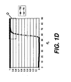
- Figures 1B - 1D the transmission value for light of S-polarization (polarized perpendicular to the plane of incidence and designated by the circles in Figure 1A ) at various acceptance angles ⁇ a is given by curve T90 (filled squares).
- the reflectivity for the orthogonal polarization, or P-polarization (polarized parallel to the plane of incidence and designated by the lines in Figure 1A ) is given by curve R0 (open triangles).
- R0 open triangles
- dashed box Q in Figure 1B good separation of light in the range from 51-90 degrees is desired for polarization of light from the light guide plate. Light separation is considered to be acceptable when both T90 and R0 values exceed about 0.8, indicating that 4:1 or better polarization separation is achieved.
- exemplary values are given for indices n LGP , n e . and n o .
- the depth D is the thickness of the birefringent polarization material.
- the overlap angle range and effective acceptance angle ⁇ a range given in the right-most columns.
- 89 degree value shown in tables and used in description in the present disclosure is used to express an angular value for acceptance angle ⁇ a that can approach 90 degrees as a limit, but is less than 90 degrees.
- the overlapping angle ⁇ is between 71° and 89°, which is about half the desired 51-90 degree range.
- Light between 51 ° and 71 ° is not well-polarized.
- n o 1.389.
- Light guide plate 12 must have an index of refraction n LGP that is substantially equal to the larger of the extraordinary index n e and ordinary index n o .
- the smaller of the extraordinary index n e and ordinary index n o is usually greater than 1.50, which means that the light guide plate must have relatively large index of refraction n LGP , for example, that of polycarbonate, 1.589.
- this is undesirable or unworkable, because the most commonly used light guide plate is made of poly(methyl methacrylate) (PMMA) with index of refraction of around 1.49.
- PMMA poly(methyl methacrylate)
- the invention provides a backlight unit comprising in order:
- the present invention addresses the problem of angular limitation for polarizing light within the light guide plate by using a novel application of formed birefringence.
- Formed birefringence also termed form birefringence, uses devices having generally periodic structures with features and spacing, or pitch dimensions, smaller than a wavelength.
- the formed birefringence principle is used, for example, in wire grid polarizers that use a grating of conductive wires having sufficiently high spatial frequency that zero order light is no longer diffracted and optical path lengths parallel and perpendicular to the grating features are distinct.
- wire-grid polarizer is given in U.S. Patent No. 6,788,461 entitled "Wire Grid Polarizer" to Kurtz et al.
- These conventional solutions employ conductive metal wires or elongated metal layers for polarization. While such devices are capable of providing good separation of polarization states, however, their use of metal materials has unwanted side effects due to some inherent amount of light absorption.
- a layer is formed comprising two dielectric, non-conductive materials, extended in length along the general direction of light propagation, one with a high index of refraction n 1 and the other with a low index of refraction n 2 .
- the two dielectric materials can be isotropic or birefringent.
- the two dielectric materials are isotropic, that is, that each material has only one index of refraction.
- the resulting reflective polarizer of the present invention is structured in such a way that formed birefringence is effected by this arrangement, so that the layer is approximately equivalent in behavior to a layer of highly birefringent material with effective extraordinary index n e and ordinary index n o .
- the effective extraordinary index n e and ordinary index n o that are obtained as a result of the formed birefringent structure are typically different from the indices n 1 and n 2 of the original materials.
- n 1 and n 2 are typically complex numbers for conductive materials, so that the formed birefringence is also a complex number. This arrangement implies some inherent amount of absorption when using conductive materials.
- the reflective polarizer according to this invention has three important advantages that are of particular value for display applications.
- the device provides a high level of birefringence
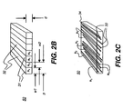
- FIG. 2A shows a backlight apparatus 38 having light guide plate 12 in optical contact with a reflective polarizer 50 based on formed birefringence according to the present invention.
- Light guide plate 12 has an incident face 16 facing light source 14.
- reflective polarizer 50 may be sandwiched between light guide plate 12 and another layer of transparent substrate material, typically a material having the same index of refraction as light guide plate 12.
- Reflective polarizer 50 is in optical contact with light guide plate 12.
- Optical contact as the term is used in the present disclosure, is equivalent to physical contact or, optionally, to coupling through an optical adhesive. There is no air gap between reflective polarizer 50 and light guide plate 12.
- Reflective polarizer 50 has a number of elongated channels 31 and 32, extended in a length direction that is generally perpendicular to incident face 16 and distributed widthwise in an alternating pattern.
- the channels are generally perpendicular if at 90° to the incident face or within ⁇ 15degrees.
- Each channel 31, 32 is formed using a non-conductive or dielectric optical material.
- channels 31 and 32 have different indices of refraction n 1 and n 2 .
- channels 31 and 32 are sub-wavelength in width for light of visible wavelengths, generally less than about 150 nm, and extend along the length of reflective polarizer 20, in a direction parallel to the page, or perpendicular incident face 16.
- the reflective polarizer 50 has efficient extraordinary and ordinary refractive indices n e and n o .
- the direction of the extraordinary refractive index n e is perpendicular to the length direction of channels 31 and 32.
- Index n o then applies for light having a polarization axis that is perpendicular to n e .
- Figure 2B shows some important dimensions that determine the polarization behavior of reflective polarizer 50. These include:
- pitch P is intended to include average pitch, where there may be some variation in pitch as a result of fabrication.
- Figure 2C shows another embodiment of reflective polarizer 50, having a dispersed material 33 embedded within a matrix material 34, arranged in an alternate pattern that can exhibit the same response as the periodic pattern of Figure 2B , but with an aperiodic distribution of channels.
- the dispersed material 33 may have higher or lower index than the matrix material 34.
- the width dimensions of the embedded material are small compared to the wavelength of the visible light, and are preferably smaller than 150 nm, and more preferably smaller than 100 nm. A pitch P of less than 150 nm is preferred.
- the shape of the embedded material is preferably elongated.
- the matrix and dispersed materials can be isotropic or birefringent materials. A large formed birefringence value can also be provided from this configuration.
- the volume fraction of the embedded (or dispersed) material is related to the fill factor f 1 of the reflective polarizer shown in Figure 2B .
- the zero-order value is best applied where the pitch P is very small relative to the wavelengths of incident light, so that: P ⁇ ⁇ 0 Where pitch P ⁇ is not negligible, the second order equations are likely to be more accurate.
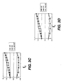
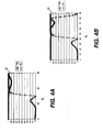
- Figures 4A-4F and 5A-5J show a few examples of the reflective polarizer based on formed birefringence according to the present invention and using some different possible values for indices n LGP , n 1 , n 2 , depth d and fill factor f 1 .
- the pitch P is 140 nm, and the wavelength of interest is 550 nm.
- the pitch P is 100 nm, and the wavelength of interest is also 550 nm.
- Reference dashed box Q shown in Figures 4A-5J shows the range of acceptance angles ⁇ a of interest, here 51-90 degrees and facilitates comparison of the reflective polarizer of the present invention with conventional reflective polarizers as shown earlier in Figures 1B - 1D .
- the high index of refraction n 1 is 2.35
- the low index of refraction n 2 is 1.0.
- the thickness of the reflective polarizer is 0.5 mm.
- this reflective polarizer embodiment of the present invention provides a significant improvement over conventional reflective polarizers such as those described with reference to Figures 1B-1D , with good effective separation of polarization states over a broader range of light acceptance angles ⁇ a .
- Table 2 that follows gives a summary of parameters and performance values that apply for Figures 4A through 4F .
- the depth d and fill factor f 1 values vary from one example to the next.
- the overlapping angle ⁇ a range is between 46° and 82°, wider in the lower bound but not optimal for light at higher angles.
- the overlapping angle ⁇ is between 59° and 77°, which is narrower with respect to both lower and upper bounds.
- the overlapping angle ⁇ is between 51° and 79°, which has about the same lower bound and narrower upper bound.
- the overlapping angle ⁇ is between 50° and 72°, which has about the same lower bound and narrower upper bound.
- the overlapping angle ⁇ is between 51° and 72°, which has about the same lower bound and upper bound as the Figure 4E example.
- FIG. 4B 2.35 1.0 0.50 0.30 46°, 89° 0°,82° 46°, 82° 37° 3
- FIG. 4C 2.35 1.0 0.50 0.50 59°, 89° 0°,77° 59°, 77° 19° 4
- FIG. 4D 2.35 1.0 0.40 0.38 51°, 89° 0°,79° 51°, 79° 29° 5
- FIG. 4E 2.35 1.0 0.60 0.38 50°, 89° 0°,72° 50°, 72° 23° 6
- FIG. 4F 2.35 1.0 5.0 0.38 51°, 89° 0°,72° 51°, 72° 22° Note 1 -
- the ⁇ a range includes all angles in the given overlap range.
- FIGS. 5A through 5J show performance of a reflective polarizer according to the present invention with slightly different parameters than were given for the examples of Figures 4A through 4F , notably, a different substrate index of refraction n LGP .
- the LGP index of refraction n LGP 1.49, so that that the acceptance angle ⁇ a of light trapped within the light guide is in the range given by about 48° ⁇ ⁇ a ⁇ 90°.
- the most commonly used light guide plate material is PMMA with an index of refraction of around 1.49.
- Reference dashed box Q shown in Figures 5A-5J shows the range of acceptance angles ⁇ a of interest, from about 48-90 degrees, with values for T90 and R0 above 0.8, and facilitates comparison of the reflective polarizer of the present invention with conventional reflective polarizers, as shown earlier in Figures 1B - 1D , and with the inventive examples of Figures 4A through 4F .
- the high index of refraction n 1 is 1.80, and the low index of refraction n 2 is 1.0.
- the pitch P 140 nm.
- the thickness of the reflective polarizer is 0.5 mm.
- reflection R0 exceeds 80% for acceptance angles ⁇ a above about 59°, indicating that light of this polarization is reflected from the reflective polarizer.
- This reflective polarizer design is thus significantly improved over conventional reflective polarizers, but not quite as good as some of the earlier examples given.
- the high index of refraction n 1 is 1.589, which corresponds to that used in the Li et al. '423 disclosure (referring to Figs. 12 and 13 in the '423 disclosure).
- the low index of refraction n 2 is 1.0.
- Transmission T90 is greater than 95% for all acceptance angles ⁇ a .
- Reflection R0 is greater than 80% for acceptance angles above 71°.
- R0 is greater than 50% for 67.5° ⁇ ⁇ a ⁇ 90°.
- this reflective polarizer has comparable polarization separation efficiency to that of conventional reflective polarizers, with the advantage of using a substrate with lower index of refraction (1.49 vs. 1.589).
- performance is at least as good as that described in the Li et al. '423 disclosure, but using standard LGP 12 material (PMMA) rather than the less commonly used polycarbonate material that the Li et al. solution resorts to.
- the overall separation performance is similar to that described in the Li et al. '423 disclosure.
- Figure 5D is similar to that of Figure 5B , but with the high index of refraction n 1 at 2.35.
- FIG. 5B 1.589 1.0 0.5 0.787 71°, 89° 0°, 89° 71°, 89° 29° 9
- FIG. 5C 1.589 1.0 5.0 0.785 69°, 89° 0°, 89° 69°, 89° 21° 10
- FIG. 5D 2.35 1.0 0.5 0.5 69°, 89° 0°, 89° 69°, 89° 21° 11
- FIG. 5E 2.35 1.0 0.5 0.45 62°, 89° 0°, 78° 62°, 78° 17° 12
- FIG. 5F 2.35 1.0 0.5 0.6 89°, 89° 0°, 70° None --- 13
- FIG. 5F 2.35 1.0 0.5 0.6 89°, 89° 0°, 70° None --- 13 FIG.
- FIG. 5G 2.35 1.0 0.4 0.5 72°, 89° 0°, 71° None --- 14 FIG. 5H 2.35 1.0 0.6 0.5 67°, 89° 0°, 70° 67°, 70° 4° 15
- FIG. 5I 1.8 1.0 0.6 0.524 68°, 89° 0°, 84° 58°, 84° 27° 1.6
- FIG. 5J 1.8 1.0 0.6 0.534 59°, 89° 0°, 89° 59°, 89° 31° Note 1 - The ⁇ a range includes all angles in the given overlap range.
- FIGS. 4A-4F and 5A-5J are not limiting but are for illustration purposes. Many other parameter variations would be allowed.
- the shape of channels 31, 32 can be varied from the rectangular cross-section shown in Figures 2A and 2B ; other shapes known in the art can be used as well.
- the pitch P can be longer or shorter, as long as only zero order diffraction occurs.
- the low index material does not need to be air, but could also be any of various materials having a relatively low index of refraction, such as MgF 2 , for example. Both the high and low index materials can also be birefringent, as long as their optic axes are aligned in parallel.
- any of a number of different fabrication techniques could be used for forming reflective polarizer 50.
- the channel structure can be directly patterned into the substrate that will form channels 31 using standard photolithography.
- Other methods could use deposition of material 31 onto the substrate using inkjet printing or other precision deposition techniques.
- a metal layer could be applied as a mask for subsequent etching.
- a metal layer is deposited, using a metal such as aluminum.
- the deposition method can be one of several standard methods including thermal evaporation or sputtering.
- the metal is patterned using standard photolithography followed by a metal etch (possibly dry metal etch such as CC14, BC13) to form a mask pattern. Channels 32 can then be etched to remove unwanted material, leaving the desired void for air.
- etching the dielectric or ion beam milling could be employed.
- Lift off methods can also be used.
- Wet etch using etch compounds such as HF for a SiO2 etch could be used.
- multiple layers of dielectric materials could be deposited to form either or both channels 31 and 32. This type of fabrication would require repeated processes of deposition and etching until the proper depth d ( Figure 2B ) is attained.
- voided air is mixed with an inorganic or organic binder having a suitable index of refraction.
- the medium is then stretched along one direction.
- the dimension of the voided air is smaller than wavelength of light in this direction, and is larger than a few wavelengths of light in the orthogonal direction.
- the relative ratio of voids to binder is equivalent to the fill factor f 1 of the channel, which determines the effective extraordinary and ordinary indices n e and n o .
- Reflective polarizer 50 of the present invention can be used for display backplane illumination in a number of different possible embodiments.
- reflective polarizer 50 is used in optical contact with a tapered light guide plate 30, and a light redirecting film 26 in a display 36.
- This combination of backplane illumination components directs polarized light through LCD modulator 40, enhances light utilizing efficiency, and reduces the requirement for polarization components that are normally provided as part of LCD modulator 40.
- polarization converter such as a quarter-wave film or plate located on the bottom face 18 and/or the end face 19.
- Figure 6B shows reflective polarizer 50 used in optical contact with a flat or non-tapered light guide plate 12.
- Reflective polarizer 50 can be combined with light guide plate 12 in a number of different possible configurations.
- Figures 6A and 6B show examples in which reflective polarizer 50 is positioned toward the top surface of light guide plate 12.
- Figures 6C, 6D , and 6E show embodiments that position reflective polarizer 50 toward the base of light guide plate 12.
- the location of reflective polarizer 50 of the present invention and the light redirection components appear to be important in order to obtain suitable performance levels with these embodiments.
- Figure 6E shows how light extraction features must be arranged in order to use reflective polarizer 50 effectively if positioned toward the base of light guide plate 12.
- a light extraction structure 25a is placed on the bottom face 18 of the light guide plate 12.
- the reflective polarizer of the present invention provides improved polarization separation over the broad range of angles of light within the light guide plate.
- the reflective polarizer of the present invention provides a high degree of polarization separation in a compact, low-cost component.
Landscapes
- Physics & Mathematics (AREA)
- General Physics & Mathematics (AREA)
- Optics & Photonics (AREA)
- Nonlinear Science (AREA)
- Mathematical Physics (AREA)
- Chemical & Material Sciences (AREA)
- Crystallography & Structural Chemistry (AREA)
- Polarising Elements (AREA)
- Planar Illumination Modules (AREA)
- Liquid Crystal (AREA)
Abstract
A backlight unit comprises:
(1) a light source (14);
(2) a light guide plate (LGP) (12) having an incident face (16) toward the light source (14) and having a refractive index nLGP ;
(3) a reflective polarizer (50) having formed birefringence in optical contact with the LGP (12) including a layer having parameters of the reflective polarizer (50) selected to provide R0>0.8 for one polarization state and T90>0.8 for the orthogonal polarization state, for light of wavelength of 550 nm, for least one reflective polarizer angle of light incidence θa.
Description
- The present invention generally relates to display illumination and more particularly relates to a backlight unit employing a reflective polarizer based on formed birefringence for use with light having a large incident angle.
- Liquid Crystal Displays (LCDs) are widely used in a broad range of display devices and compete favorably with the more conventional cathode-ray tube (CRT) monitor for numerous display applications. While direct-view LCDs continually improve in resolution, speed, and overall performance, however, display brightness can still be disappointing when compared against CRTs. This shortcoming is particularly noticeable over larger viewing angles.
- An inherent problem with LCD displays that limits brightness relates to polarization dependence. In typical applications, the LCD device itself has a pair of absorptive polarizers that absorb half of the unpolarized light emitted from the light source. Thus, even where brighter light sources can be provided, a considerable portion of this light is still discarded.
- One solution to this problem has been to use a reflective polarizer, such as Vikuiti™ Dual Brightness Enhancement Film, manufactured by 3M, St. Paul, MN or wire grid polarizer wire-grid polarizer available from Moxtek, Inc., Orem, Utah. These devices transmit only the light having the desired polarization for the LCD and reflect light of the orthogonal polarization, which can be re-oriented by illumination components so that it is eventually used.
- Reflective polarizers work well for a portion of the light, particularly for light at incident angles near normal with respect to the reflective polarizer. However, light incident at angles diverging from normal, or large-angle light, is not used efficiently. This inefficiency can be difficult to remedy, since some deliberate scattering of light is typically performed within the light guide plate (LGP). Scattering elements, such as printed dots or an etched pattern, are often necessary for uniformizing the light in a conventional backlight system. Thus, uniformization and polarization elements may tend to work at cross-purposes, requiring some compromise to achieve both suitable brightness and acceptable uni formity.
- One approach using a reflective polarizer, or polarizing beamsplitter, positions this polarizing component at the bottom face of a light guide plate without any scattering element, as disclosed in
U.S. Patent No. 6,285,423 to Li et al. (see '423 Li et al.Fig. 1a , numeral 20). With this type of arrangement, light transmitted through the reflective polarizer is redirected as illumination output at near normal angles. Light reflected by the reflective polarizer is directed to a polarization converter for changing the polarization of at least a portion of this light and redirecting it for eventual output. - An alternate approach using a reflective polarizer positions this element at the top of a light guide plate without any scattering element, as disclosed in
U.S. Patent No. 6,443,585 to Saccomanno (see '585 SaccomannoFig. 1 numeral 8). This approach generally provides higher light extraction efficiency due to reduced loss in scattering, but it does not provide a satisfactory polarizing effect. - In order to understand the problems with reflective polarizer use encountered with both the Li et al. '423 and Saccomanno '585 approaches, it is useful to observe how polarized light is handled within the light guide plate of an illumination system. To do this, compare the schematic view of
Figure 1A in the present disclosure withFig. 1A of the Li et al. 6,285,423 disclosure andFig. 1 of the Saccomanno 6,443,585 disclosure. A beam oflight 10 is emitted from alight source 14 that is positioned at the entrant plane of alight guide plate 12. The incident angle at the entrant plane is θi , which is between 0 and 90° in the most general case. Beam oflight 10 is then coupled intolight guide plate 12 and is incident on areflective polarizer 20. Polarization states are represented using standard schematic notation: S-polarization is represented by a large dot along the line of light, P-polarization is shown by a line orthogonal to the line of light. Threelight extraction structures 25 for defeating TIR at the surface oflight guide plate 12 are shown; a number of different films or structures, well known in the backlighting illumination arts, could be utilized for this purpose. A polarization converter, such as a quarter-wave film or plate, is located onbottom face 18 or onend face 19, or on both bottom andend faces - A detailed description of a conventional
reflective polarizer 20 can be found in theLi et al. 6,285,423 disclosure. Briefly, according to conventional practice,reflective polarizer 20 can have a number of possible forms, including: - (1) a stack of 1.38/2.35 dielectric layers deposited on polycarbonate substrates; (2) a stack of metal/dielectric layers on a substrate; (3) a layer of birefi-ingent material such as liquid crystalline material sandwiched between two substrates; or (4) a stretched plastic film with a blend of birefringent material and isotropic material, as shown in Figs. 8c, 10c, and 12c of
U.S. Patent No. 6,285,423 . However, it must be emphasized that the polarizing effect is achieved only when the light is within the limited acceptance angle range of the device. According to configurations shown in the Li et al. '423 disclosure, the acceptance angle (referred to as the incident angle in the Li et al. '423 patent) is either in the range 69° to 79° (see Li et al. '423 patent, Fig. 9); 62° to 82° (see Li et al. '423 patent, Fig. 11); or 70° to 84° (see Li et al. '423 patent, Fig. 13). - When the following condition is met for angle θTIR, the reflective polarizer transmits one polarization and reflects the other polarization due to total internal reflection (TIR), thus separating two polarization states for all light trapped in the light guide plate:

and
where nLGP is the index of refraction of the light guide plate substrate, no is the extraordinary index of refraction, ne is the ordinary index of refraction. - For a better understanding of the limitations on light incident angle inherent to the conventional approach used in the Li et al. '423 disclosure, it is particularly instructive to take a closer look at the case when
reflective polarizer 20 is a layer of birefringent material with extraordinary index ne and ordinary index no. In this particular case, the direction of ne is parallel to thelight source 14 or perpendicular to the plane of incidence shown inFigure 1A . Using the values used in Li et al. '423 by way of example:
and
- The light trapped in the light guide has an acceptance angle θa , which is bounded as follows:

that is, for a substrate with index nLGP = 1.589 :
Thus, light between 51 and 90 degrees is within the acceptance angle for the light guide. - However, a good polarization separation is provided only where there is total internal reflection, that is, only for light with incident angle greater than

reflective polarizer 20 does not provide satisfactory polarization separation effect for light with incident angles between 51° and 71°. Only for light that is in the 71-90 degree range is acceptable polarization separation provided. - Table I and the comparative examples of accompanying
Figures 1B, 1C , and1D show the shortcomings of the conventional approach to reflective polarizer structure, such as the approach described in the Li et al. '423 disclosure (see Li et al. '423 col. 8, lines 66 - 67). These examples show a polycarbonate substrate, having nLGP =1.589. InFigures 1B - 1D , the transmission value for light of S-polarization (polarized perpendicular to the plane of incidence and designated by the circles inFigure 1A ) at various acceptance angles θ a is given by curve T90 (filled squares). The reflectivity for the orthogonal polarization, or P-polarization (polarized parallel to the plane of incidence and designated by the lines inFigure 1A ) is given by curve R0 (open triangles). As shown by dashed box Q inFigure 1B , good separation of light in the range from 51-90 degrees is desired for polarization of light from the light guide plate. Light separation is considered to be acceptable when both T90 and R0 values exceed about 0.8, indicating that 4:1 or better polarization separation is achieved. - In Table 1, exemplary values are given for indices nLGP, ne. and no. The depth D is the thickness of the birefringent polarization material. Of particular interest for overall performance is the overlap angle range and effective acceptance angle θ a range given in the right-most columns.
- It is to be noted that the 89 degree value shown in tables and used in description in the present disclosure is used to express an angular value for acceptance angle θ a that can approach 90 degrees as a limit, but is less than 90 degrees.
- For the example of
Figure 1B with depth D = 5 µm, the overlapping angle θ is between 71° and 89°, which is about half the desired 51-90 degree range. Light between 51 ° and 71 ° is not well-polarized. The example ofFigure 1C exhibits at least some improvement by using a birefringent layer that has very low ordinary index no = 1.389. However, this is a theoretical material that yields a very large birefringence of 0.2, given ne = 1.589. It would be unusual to find a usable material having a birefringence of this value for sheet reflective polarizer use, given ne = 1.589. Even if such a material were available, however, the overlapping angle θa is only between 61° and 89°, which still fails to span the desired range. - The example of
Figure 1D comes just a bit closer to the desired performance by using the theoretical material of theFigure 1C example and varying the depth D of the birefringent layer D = 0.5 µm.Table 1: Summary of Parameters and Performance for Conventional Polarizers (LGP substrate nLGP =1.589) FIG. ne no D (µm) θR (where R0 >0.8) θT (where T90>0.8) θa of overlap (T90 >0.8 R0>0.8) θ a range (Note 2) 1B 1.589 1.5 5.0 71°, 89° 0°, 89° 71 °, 89° 19° 1C 1.589 1.389 5.0 61°, 89° 0°, 89° 61°,89°
(Note 1)29° 1D 1.389 1.389 0.5 61°, 89° 0°, 89° 61°, 89°
(Note 1)29° Note 1 - Best theoretical values given.
Note 2 - The θ a range includes all angles in the given overlap range. - As the comparative examples of
Figures 1B-1D show, conventional solutions to remedy this limitation can be severely hampered by the physical characteristics of the optical materials themselves. For example, this constraint in functional θ a range from 71-90 degrees could be eased somewhat if a birefringent material having sufficiently large birefringence were to be used. A birefringence larger than 0.35, for example, would alleviate this problem. - However, materials with large birefringence and other desired properties are not easily available, may not be usable for reflective polarizer use, or may not even exist.
Light guide plate 12 must have an index of refraction nLGP that is substantially equal to the larger of the extraordinary index ne and ordinary index no. The smaller of the extraordinary index ne and ordinary index n o is usually greater than 1.50, which means that the light guide plate must have relatively large index of refraction nLGP, for example, that of polycarbonate, 1.589. However, this is undesirable or unworkable, because the most commonly used light guide plate is made of poly(methyl methacrylate) (PMMA) with index of refraction of around 1.49. Thus, solutions using high levels of birefringence are constrained by properties of the dielectric materials themselves. - Clearly, a good portion of the light incident from light source 14 (
Figure 1A ) is not used when the reflective polarizer solution described by Li et al. and shown inFigure 1 of the '423 disclosure is employed. Again, with this type of conventional solution, while light in the 51-90 degree θ a range is available, acceptable polarization separation is provided only for light that is in the 71-90 degree range. For the materials most commonly used for light guide plates, no suitable solution has yet been provided for a reflective polarizer that works over the full θ a range of light angles within the light guide plate. Attempts to alleviate this problem using conventional approaches have been thwarted by the limitations of the optical materials themselves. There is, therefore, a need for an illumination solution that provides polarized light over a broader incident angle range than is permissible when using conventional reflective polarizer techniques. - The invention provides a backlight unit comprising in order:
- (1) a light source;
- (2) a light guide plate (LGP) having an incident face toward the light source and having a refractive index nLGP;
- (3) a reflective polarizer having formed birefringence in optical contact with the LGP including a layer having:
- (a) an elongated non-conductive first material with refractive index n1 ;
- (b) an elongated non-conductive second material with a refractive index n2 different by at least 0.2 from that of the first material;
- (i) the cross-sectional dimensions of the first and second materials, in a plane parallel to the light incident face of the LGP, are smaller than 100 nm in their width dimensions; and
- (ii) the parameters of the reflective polarizer are selected to provide R0>0.8 for one polarization state and T90>0.8 for the orthogonal polarization state, for light of wavelength of 550 nm, for least one reflective polarizer angle of light incidence θa.
- It is a feature of the present invention that it uses formed birefringence to obtain high levels of polarization separation using conventionally available materials.
- It is an advantage of the present invention that it provides a reflective polarizer for an illumination apparatus that can exhibit the needed level of polarization separation for use with a light guiding plate in a number of display applications.
- These and other aspects, objects, features and advantages of the present invention will be more clearly understood and appreciated from a review of the following detailed description of the preferred embodiments and appended claims, and by reference to the accompanying drawings.
- While the specification concludes with claims particularly pointing out and distinctly claiming the subject matter of the present invention, it is believed that the invention will be better understood from the following description when taken in conjunction with the accompanying drawings, wherein:
-
Figure 1A shows the problem to be solved using a schematic cross-sectional view with a backlight unit having a reflective polarizer; -
Figures 1B, 1C , and1D are graphs of comparative examples that show theoretical performance that can be achieved using conventional methods and materials for a reflective polarizer; -
Figure 2A is a schematic perspective view showing a backlight unit having a reflective polarizer based on formed birefringence according to the present invention; -
Figure 2B shows a perspective view of one embodiment of the reflective polarizer used inFigure 2A ; -
Figure 2C shows a perspective view of another embodiment of the reflective polarizer used inFigure 2A ; -
Figures 3A-3D show effective extraordinary index ne and ordinary index no , and birefringence Δn = ne - no as a function of fill factor f 1 ; -
Figures 4A-4F show the performance of the reflective polarizers having various dimensional and optical parameters with nLGP =1.589; -
Figures 5A-5J show the performance of the examples having various dimensional and optical parameters with nLGP =1.49; -
Figure 6A shows the use of the reflective polarizer in combination with a tapered light guide and a light redirecting film according to one embodiment of the present invention; -
Figure 6B shows the use of the reflective polarizer in combination with a light extraction article according to another embodiment of the present invention; -
Figure 6C shows the use of the reflective polarizer positioned toward the bottom face of the light guide plate according to one comparative example; -
Figure 6D shows another use of the reflective polarizer positioned toward the bottom face of the light guide plate according to another comparative example; and -
Figure 6E shows the use of the reflective polarizer positioned toward the bottom face of the light guide plate according to an embodiment of the present invention. - The present description is directed in particular to elements forming part of, or cooperating more directly with, apparatus in accordance with the invention. It is to be understood that elements not specifically shown or described may take various forms well known to those skilled in the art.
- Figures showing the structure and arrangement of the reflective polarizer of the present invention are not drawn with attention to scale, but are provided to show overall structure, composition, and function.
- The present invention addresses the problem of angular limitation for polarizing light within the light guide plate by using a novel application of formed birefringence. Formed birefringence, also termed form birefringence, uses devices having generally periodic structures with features and spacing, or pitch dimensions, smaller than a wavelength. The formed birefringence principle is used, for example, in wire grid polarizers that use a grating of conductive wires having sufficiently high spatial frequency that zero order light is no longer diffracted and optical path lengths parallel and perpendicular to the grating features are distinct. One example of a wire-grid polarizer is given in
U.S. Patent No. 6,788,461 entitled "Wire Grid Polarizer" to Kurtz et al. These conventional solutions employ conductive metal wires or elongated metal layers for polarization. While such devices are capable of providing good separation of polarization states, however, their use of metal materials has unwanted side effects due to some inherent amount of light absorption. - In the present invention, however, instead of using reflective and conductive wires, a layer is formed comprising two dielectric, non-conductive materials, extended in length along the general direction of light propagation, one with a high index of refraction n 1 and the other with a low index of refraction n 2 . The two dielectric materials can be isotropic or birefringent. For illustration purposes, all the examples given in this disclosure assume that the two dielectric materials are isotropic, that is, that each material has only one index of refraction. The resulting reflective polarizer of the present invention is structured in such a way that formed birefringence is effected by this arrangement, so that the layer is approximately equivalent in behavior to a layer of highly birefringent material with effective extraordinary index ne and ordinary index no . Here, the effective extraordinary index ne and ordinary index no that are obtained as a result of the formed birefringent structure are typically different from the indices n1 and n2 of the original materials. The formed birefringence of this structure is always calculated as a negative number, i.e., Δn = ne - no < 0. In practice, however, since the difference is the quantity of interest, the absolute value |Δn| can be used to quantify birefringence. As a comparison, one or both of n1 and n2 are typically complex numbers for conductive materials, so that the formed birefringence is also a complex number. This arrangement implies some inherent amount of absorption when using conductive materials.
- The reflective polarizer according to this invention has three important advantages that are of particular value for display applications. First, the device provides a high level of birefringence |Δn| in a range of 0.2-0.5 or greater, well above the birefringence obtained by conventional reflective polarizers that use a single birefringent material. This is made possible with two isotropic materials, one with a low index of refraction n 2 , as low as 1.0 (air), and, the other, a high index of refraction n 1 as large as 1.6-1.8 (with some plastics), and even as large as 2.35 (using inorganic materials such as TiO2.) Second, the effective ordinary index no can be adjusted to a low value. Thus, it is possible to use an LGP substrate with low index of refraction that satisfies n o = nLGP > ne , where nLGP is the refractive index of the LGP substrate, an important relationship for reflective polarizer use with backlighting apparatus, as noted earlier. Third, this reflective polarizer has little absorption due to the fact that both n 1 and n 2 are real numbers for dielectric, non-conductive materials. As noted earlier, this is in contrast to the conventional conductive wire grid polarizer that exhibits some intrinsic absorption.
- The perspective view of
Figure 2A shows abacklight apparatus 38 havinglight guide plate 12 in optical contact with areflective polarizer 50 based on formed birefringence according to the present invention.Light guide plate 12 has anincident face 16 facinglight source 14. As shown inFigure 2A ,reflective polarizer 50 may be sandwiched betweenlight guide plate 12 and another layer of transparent substrate material, typically a material having the same index of refraction aslight guide plate 12. -
Reflective polarizer 50 is in optical contact withlight guide plate 12. Optical contact, as the term is used in the present disclosure, is equivalent to physical contact or, optionally, to coupling through an optical adhesive. There is no air gap betweenreflective polarizer 50 andlight guide plate 12. -
Reflective polarizer 50 has a number ofelongated channels incident face 16 and distributed widthwise in an alternating pattern. The channels are generally perpendicular if at 90° to the incident face or within ± 15degrees. Eachchannel Figure 2A and in cross section inFigure 2B ,channels channels reflective polarizer 20, in a direction parallel to the page, orperpendicular incident face 16. Consequently, thereflective polarizer 50 has efficient extraordinary and ordinary refractive indices ne and no . The direction of the extraordinary refractive index ne is perpendicular to the length direction ofchannels - In a comparative example, consider
channels Figure 2A , that is, parallel toincident face 16. This arrangement would result in the direction of the extraordinary refractive index ne being perpendicular to the length direction oflight source 14. Thus, light polarized in the plane of the incidence would encounter the combination of ne and no , making it difficult to sustain total internal reflection at the reflective polarizer surface. -
Figure 2B shows some important dimensions that determine the polarization behavior ofreflective polarizer 50. These include: - w1, w2: cross-sectional widths for
channels - P: pitch for
channels - d: depth for
channels - In the context of the present disclosure, pitch P is intended to include average pitch, where there may be some variation in pitch as a result of fabrication.
-
Figure 2C shows another embodiment ofreflective polarizer 50, having a dispersedmaterial 33 embedded within amatrix material 34, arranged in an alternate pattern that can exhibit the same response as the periodic pattern ofFigure 2B , but with an aperiodic distribution of channels. The dispersedmaterial 33 may have higher or lower index than thematrix material 34. The width dimensions of the embedded material are small compared to the wavelength of the visible light, and are preferably smaller than 150 nm, and more preferably smaller than 100 nm. A pitch P of less than 150 nm is preferred. The shape of the embedded material is preferably elongated. The matrix and dispersed materials can be isotropic or birefringent materials. A large formed birefringence value can also be provided from this configuration. The volume fraction of the embedded (or dispersed) material is related to the fill factor f1 of the reflective polarizer shown inFigure 2B . - For the formed birefringence embodiments of
Figures 2A and2B , graphs inFigures 3A-3D show the effective extraordinary index ne and ordinary index no , and birefringence Δn = ne - no as a function of fill factor f 1. Under normal incidence, the effective ne and no indices can be given by the zero-order effective medium theory:

Alternately, the second-order effective medium theory can be used, with the following computations:

- In general, the zero-order value is best applied where the pitch P is very small relative to the wavelengths of incident light, so that:

Where pitch
- In
Figure 3A (for zero-order) andFigure 3B (for second-order), the respective indices are n 1 = 2.35 n 2 = 1.0. InFigure 3A , for example, a relatively high birefringence value of about -0.5 can be obtained using a fill factor f1 value of approximately 0.6. - In
Figure 3C (for zero-order) andFigure 3D (for second-order), the respective indices are n 1 =1.8, n 2 =1.0. - In summary, it can be seen from
Figures 3A through 3D that a relatively large birefringence value (again, in terms of absolute value) can be obtained using two regular isotropic dielectric materials using the elongated channel arrangement described. -
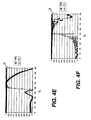
Figures 4A-4F and5A-5J show a few examples of the reflective polarizer based on formed birefringence according to the present invention and using some different possible values for indices nLGP, n1, n2, depth d and fill factor f1. For the examples ofFigures 4A-4F , theLGP 12 substrate is polycarbonate with nLGP = 1.589. For the examples ofFigures 5A-5J , theLGP 12 substrate is PMMA with nLGP = 1.49. In Examples ofFigures 4A-4F and5A-5H , the pitch P is 140 nm, and the wavelength of interest is 550 nm. In Examples 5I and 5J, the pitch P is 100 nm, and the wavelength of interest is also 550 nm. - Reference dashed box Q shown in
Figures 4A-5J shows the range of acceptance angles θa of interest, here 51-90 degrees and facilitates comparison of the reflective polarizer of the present invention with conventional reflective polarizers as shown earlier inFigures 1B - 1D . - Analyses were modeled at 550 nm using the Gsolver grating analysis software tool, which allows sub-wavelength structures to be thoroughly modeled using rigorous coupled wave analysis (RCWA). Gsolver software is commercially available from Grating Solver Development Company, P.O. Box 353, Allen, Tex.
- Turning to the example of
Figure 4A , the substrate index of refraction is nLGP =1.589 , so that that the acceptance angle θa of light trapped in the light guide is in the range given by 51° ≤ θ a < 90°, as was described earlier with reference to examples given in the Li et al. '423 patent and summarized in the graphs ofFigures 1B, 1C , and1D . The high index of refraction n 1 is 2.35, and the low index of refraction n2 is 1.0. The fill factor of the high index material is f 1 = 0.38 . The thickness of the reflective polarizer is 0.5 mm. - For light polarized in a plane parallel to
channels LGP 12 substrate index nLGP . The transmission vs. acceptance angle behavior is described by curve T90 (filled squares). Because the absorption of the material is small and assumed to approximate zero, the reflection R90 = 1 - T90 and is not plotted. As shown within dashed box Q, the transmission value T90 is greater than 88% for the full range of desired acceptance angles, indicating that light of this polarization is substantially transmitted through the reflective polarizer. - For light polarized in a plane perpendicular to
channels - Given the performance shown in
Figure 4A , it can be seen that this reflective polarizer embodiment of the present invention provides a significant improvement over conventional reflective polarizers such as those described with reference toFigures 1B-1D , with good effective separation of polarization states over a broader range of light acceptance angles θ a . - Table 2 that follows gives a summary of parameters and performance values that apply for
Figures 4A through 4F . For all of the Table 2 examples, indices are nLGP =1.589, n1 = 2.35, n2 =1.0, and the pitch P = 140 nm. The depth d and fill factor f1 values vary from one example to the next. - Example 1, described with reference to the curves of
Figure 4A , with d = 0.5 µm, f1 = 0.38, provides the best performance for polarization separation, with the overlapping angle θa range (where T90 >0.8 and R0>0.8), extending from 50° through 89°. - Example 2, shown in
Figure 4B , uses the same values given in Example 1, but with fill factor f1= 0.30. The overlapping angle θ a range is between 46° and 82°, wider in the lower bound but not optimal for light at higher angles. - Example 3, shown in
Figure 4C , uses the same values given in Example 1, but with fill factor f1 = 0.50. The overlapping angle θ is between 59° and 77°, which is narrower with respect to both lower and upper bounds. - Example 4, shown in
Figure 4D , uses the same values given in Example 1, but with depth d = 0.40 µm. The overlapping angle θ is between 51° and 79°, which has about the same lower bound and narrower upper bound. - Example 5, shown in
Figure 4E , uses the same values given in Example 1, but with depth d = 0.60 µm. The overlapping angle θ is between 50° and 72°, which has about the same lower bound and narrower upper bound. - Example 6, shown in
Figure 4F , uses the same values given in Example 1, but with depth d = 5.0 µm. The overlapping angle θ is between 51° and 72°, which has about the same lower bound and upper bound as theFigure 4E example.Table 2: Summary of Figure 4A-4F Examples (Polycarbonate LGP substrate nLGP = 1.589) EX n1 n2 d (µm) f1 θR (R0 >0.8) θT (T90>0.8) θa of overlap (T90>0.8 R0>0.8) θa range (Note 1) 1 FIG. 4A 2.35 1.0 0.50 0.38 50°, 89° 0°, 89° 50°, 89° 40° 2 FIG. 4B 2.35 1.0 0.50 0.30 46°, 89° 0°,82° 46°, 82° 37° 3 FIG. 4C 2.35 1.0 0.50 0.50 59°, 89° 0°,77° 59°, 77° 19° 4 FIG. 4D 2.35 1.0 0.40 0.38 51°, 89° 0°,79° 51°, 79° 29° 5 FIG. 4E 2.35 1.0 0.60 0.38 50°, 89° 0°,72° 50°, 72° 23° 6 FIG. 4F 2.35 1.0 5.0 0.38 51°, 89° 0°,72° 51°, 72° 22° Note 1 - The θ a range includes all angles in the given overlap range. - The examples of
Figures 5A through 5J , summarized in Table 3, show performance of a reflective polarizer according to the present invention with slightly different parameters than were given for the examples ofFigures 4A through 4F , notably, a different substrate index of refraction nLGP. For these examples, the LGP index of refraction nLGP =1.49, so that that the acceptance angle θa of light trapped within the light guide is in the range given by about 48° ≤ θa < 90°. As discussed earlier, the most commonly used light guide plate material is PMMA with an index of refraction of around 1.49. Reference dashed box Q shown inFigures 5A-5J shows the range of acceptance angles θa of interest, from about 48-90 degrees, with values for T90 and R0 above 0.8, and facilitates comparison of the reflective polarizer of the present invention with conventional reflective polarizers, as shown earlier inFigures 1B - 1D , and with the inventive examples ofFigures 4A through 4F . - Referring first to
Figure 5A , the high index of refraction n 1 is 1.80, and the low index of refraction n2 is 1.0. The pitch P = 140 nm. The fill factor of the high index material is f 1 = 0.524. The thickness of the reflective polarizer is 0.5 mm. Here, reflection R0 exceeds 80% for acceptance angles θ a above about 59°, indicating that light of this polarization is reflected from the reflective polarizer. This reflective polarizer design is thus significantly improved over conventional reflective polarizers, but not quite as good as some of the earlier examples given. - In the example of
Figure 5B , the high index of refraction n 1 is 1.589, which corresponds to that used in the Li et al. '423 disclosure (referring to Figs. 12 and 13 in the '423 disclosure). The low index of refraction n2 is 1.0. The fill factor of the high index material is f 1 = 0.787. For light polarized in a plane parallel tochannels LGP 12 substrate index nLGP. Transmission T90 is greater than 95% for all acceptance angles θ a . Reflection R0 is greater than 80% for acceptance angles above 71°. R0 is greater than 50% for 67.5° ≤ θa < 90°. It can be observed that this reflective polarizer has comparable polarization separation efficiency to that of conventional reflective polarizers, with the advantage of using a substrate with lower index of refraction (1.49 vs. 1.589). Thus, even though the overall range for acceptance angle θ a is disappointing, performance is at least as good as that described in the Li et al. '423 disclosure, but usingstandard LGP 12 material (PMMA) rather than the less commonly used polycarbonate material that the Li et al. solution resorts to. - The example of
Figure 5C is similar to that ofFigure 5B , except that the thickness of the layer d= 5 µm and the fill factor of the high index material is f 1 = 0.785 . The overall separation performance is similar to that described in the Li et al. '423 disclosure. - The example of
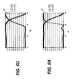
Figure 5D is similar to that ofFigure 5B , but with the high index of refraction n 1 at 2.35. The example ofFigure 5E is similar to that ofFigure 5D but with fill factor f 1 = 0.45. The example ofFigure 5F is similar to that ofFigure 5D but with f 1 = 0.6. Here, there is no overlapping area where polarization separation is acceptable. Similarly,Figure 5G shows an example with depth d = 0.4 µm and no overlapping.Figure 5H shows an example similar to that ofFigure 5G , but with depth d = 0.6 µm and very narrow overlapping.Figure 5I shows a similar example with pitch P = 100 nm instead of 140 nm.Figure 5J shows a similar example with fill factor f 1= 0.534. It can be noted that a slight change in the fill factor fl minimizes the interference effect due to the change in layer thickness.Table 3: Summary of Figure. 5A-5H Examples (PMMA LGP substrate nLGP = 1.49) EX ne no d (µm) f1 θR (R0 >0.8) θT (T90>0.8) θa of overlap (T90>0.8 R0>0.8) θa range (Note 1) 7 FIG. 5A 1.8 1.0 0.5 0.524 59°, 89° 0°, 89° 59°, 89° 31° 8 FIG. 5B 1.589 1.0 0.5 0.787 71°, 89° 0°, 89° 71°, 89° 29° 9 FIG. 5C 1.589 1.0 5.0 0.785 69°, 89° 0°, 89° 69°, 89° 21° 10 FIG. 5D 2.35 1.0 0.5 0.5 69°, 89° 0°, 89° 69°, 89° 21° 11 FIG. 5E 2.35 1.0 0.5 0.45 62°, 89° 0°, 78° 62°, 78° 17° 12 FIG. 5F 2.35 1.0 0.5 0.6 89°, 89° 0°, 70° None --- 13 FIG. 5G 2.35 1.0 0.4 0.5 72°, 89° 0°, 71° None --- 14 FIG. 5H 2.35 1.0 0.6 0.5 67°, 89° 0°, 70° 67°, 70° 4° 15 FIG. 5I 1.8 1.0 0.6 0.524 68°, 89° 0°, 84° 58°, 84° 27° 1.6 FIG. 5J 1.8 1.0 0.6 0.534 59°, 89° 0°, 89° 59°, 89° 31° Note 1 - The θ a range includes all angles in the given overlap range. - The examples given in
Figures 4A-4F and5A-5J are not limiting but are for illustration purposes. Many other parameter variations would be allowed. For example, the shape ofchannels Figures 2A and2B ; other shapes known in the art can be used as well. The pitch P can be longer or shorter, as long as only zero order diffraction occurs. The low index material does not need to be air, but could also be any of various materials having a relatively low index of refraction, such as MgF2, for example. Both the high and low index materials can also be birefringent, as long as their optic axes are aligned in parallel. - Any of a number of different fabrication techniques could be used for forming
reflective polarizer 50. For an embodiment using air inchannels 32, the channel structure can be directly patterned into the substrate that will formchannels 31 using standard photolithography. Other methods could use deposition ofmaterial 31 onto the substrate using inkjet printing or other precision deposition techniques. - In an alternate method using photolithography, a metal layer could be applied as a mask for subsequent etching. Here, a metal layer is deposited, using a metal such as aluminum. The deposition method can be one of several standard methods including thermal evaporation or sputtering. Next the metal is patterned using standard photolithography followed by a metal etch (possibly dry metal etch such as CC14, BC13) to form a mask pattern.
Channels 32 can then be etched to remove unwanted material, leaving the desired void for air. - Alternatively, methods including repeatedly etching the dielectric or ion beam milling could be employed. Lift off methods can also be used. Wet etch using etch compounds such as HF for a SiO2 etch could be used.
- In other embodiments, multiple layers of dielectric materials could be deposited to form either or both
channels Figure 2B ) is attained. - Referring back to the embodiment shown in
Figure 2C , in another method for fabrication of the reflective polarizer, voided air is mixed with an inorganic or organic binder having a suitable index of refraction. The medium is then stretched along one direction. The dimension of the voided air is smaller than wavelength of light in this direction, and is larger than a few wavelengths of light in the orthogonal direction. The relative ratio of voids to binder is equivalent to the fill factor f1 of the channel, which determines the effective extraordinary and ordinary indices n e and no. -
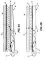
Reflective polarizer 50 of the present invention can be used for display backplane illumination in a number of different possible embodiments. Referring toFigure 6A ,reflective polarizer 50 is used in optical contact with a taperedlight guide plate 30, and alight redirecting film 26 in adisplay 36. This combination of backplane illumination components directs polarized light throughLCD modulator 40, enhances light utilizing efficiency, and reduces the requirement for polarization components that are normally provided as part ofLCD modulator 40. Note that there is polarization converter such as a quarter-wave film or plate located on thebottom face 18 and/or theend face 19. -
Figure 6B showsreflective polarizer 50 used in optical contact with a flat or non-taperedlight guide plate 12.Light extraction structures 25, either on a separate film, as indicated in dashed lines, or directly formed in or applied to the substrate surface, provide a light extraction article. As with theFigure 6A embodiment, this combination also helps to enhance light utilization efficiency and to reduce or eliminate requirements for polarization components elsewhere in the display system. -
Reflective polarizer 50 can be combined withlight guide plate 12 in a number of different possible configurations.Figures 6A and 6B show examples in whichreflective polarizer 50 is positioned toward the top surface oflight guide plate 12. -
Figures 6C, 6D , and6E show embodiments that positionreflective polarizer 50 toward the base oflight guide plate 12. The location ofreflective polarizer 50 of the present invention and the light redirection components appear to be important in order to obtain suitable performance levels with these embodiments. - Turning first to the illustrative example of
Figure 6C , the condition nLGP = no > ne is met. Consequently, the light that is polarized in the plane parallel to the channels is transmitted throughreflective polarizer 50 and light that is polarized perpendicular to the channels is reflected byreflective polarizer 50. However, light of either polarization can be directed throughlight extraction structures 25, which contradicts the function of thereflective polarizer 50. Thus, this configuration does not perform to requirements for most reflective polarizer applications. - Similarly, in
Figure 6D , the condition no > n e = nLGP is met. As a result, the light that is polarized in the plane parallel to the channels is reflected by thereflective polarizer 50 and light that is polarized perpendicular to the channels is transmitted through thereflective polarizer 50. Light of either polarization also exits from thelight extraction structures 25, similar to what is shown inFigure 6C . Therefore, this configuration is not suitable either. -
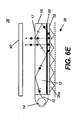
Figure 6E shows how light extraction features must be arranged in order to usereflective polarizer 50 effectively if positioned toward the base oflight guide plate 12. InFigure 6E , the condition no > ne = nLGP is met, as inFigure 6D . Here, however, alight extraction structure 25a is placed on thebottom face 18 of thelight guide plate 12. By relocating the light extraction features from thetop face 17 to bottom face aslight extraction structure 25a, light that is polarized in the plane parallel to the channels is trapped withinlight guide plate 12 until its polarization is converted to a usable state. Here, only light that has a polarization axis perpendicular to the channels is emitted from the light guide plate. - By comparison against conventional reflective polarizer solutions such as those described in the background section given earlier, the reflective polarizer of the present invention provides improved polarization separation over the broad range of angles of light within the light guide plate. By using formed birefringence, the reflective polarizer of the present invention provides a high degree of polarization separation in a compact, low-cost component.
- The entire contents of the patents and other publications referred to in this specification are incorporated herein by reference. The invention has been described in detail with particular reference to certain preferred embodiments thereof, but it will be understood that variations and modifications can be effected within the spirit and scope of the invention.
-
- 10. Beam of light
- 12. Light guide plate
- 14. Light source
- 16. Incident face
- 17. Top face
- 18. Bottom face
- 19. End face
- 20. Reflective polarizer
- 25, 25a. Light extraction structure
- 26. Light redirecting film
- 30. Tapered light guide plate
- 31, 32. Channel
- 33. Dispersed material
- 34. Matrix material
- 36. Display
- 38. Backlight apparatus
- 40. LCD modulator
- 50. Reflective polarizer
wherein:
Claims (10)
- A backlight unit comprising in order:(1) a light source;(2) a light guide plate (LGP) having an incident face toward the light source and having a refractive index nLGP ;(3) a reflective polarizer having formed birefringence in optical contact with the LGP including a layer having:in which the first material and the second materials are aligned in a direction generally perpendicular to the incident face of the LGP;(a) an elongated non-conductive first material with refractive index n1;(b) an elongated non-conductive second material with a refractive index n2 different by at least 0.2 from that of the first material;
wherein:(i) the cross-sectional dimensions of the first and second materials, in a plane parallel to the light incident face of the LGP, are smaller than 100 nm in their width dimensions; and(ii) the parameters of the reflective polarizer are selected to provide R0>0.8 for one polarization state and T90>0.8 for the orthogonal polarization state, for light of wavelength of 550 nm, for at least one reflective polarizer angle of light incidence θa. - The backlight of claim 1 wherein the parameters selected include pitch, thickness, cross-sectional width, n1, n2, nLGP, location of reflective polarizer, and fill factor.
- The backlight of claim 1 wherein the parameters selected in part (ii) satisfy the requirements over at least 20° for θa.
- The backlight of claim 1 wherein for some light incident to the reflective polarizer surface at an angle between

- The backlight unit of claim 1 wherein T0 for light having the first polarization axis substantially parallel to the incident face of the light guide plate exceeds 0.88.
- The backlight unit of claim 1 wherein R90 for light having a second polarization axis substantially perpendicular to the first polarization axis exceeds 0.88.
- The backlight unit of claim 1 wherein the reflective polarizer has a thickness that is less than 5 microns.
- The backlight of claim 1 wherein the ratio of the cross-sectional dimension of the first materials to the pitch P, wherein the pitch P equals the sum of the cross-sectional dimension of the first material plus the cross-sectional dimension of the second material of the reflective polarizer, is in the range between 0.2 and 0.8 micron.
- The backlight of claim 1 wherein the light guide plate is tapered.
- The backlight of claim 9 further comprising a light redirecting film.
Applications Claiming Priority (1)
| Application Number | Priority Date | Filing Date | Title |
|---|---|---|---|
| US11/760,863 US7618178B2 (en) | 2007-06-11 | 2007-06-11 | Backlight containing formed birefringence reflective polarizer |
Publications (1)
| Publication Number | Publication Date |
|---|---|
| EP2003394A2 true EP2003394A2 (en) | 2008-12-17 |
Family
ID=39705166
Family Applications (1)
| Application Number | Title | Priority Date | Filing Date |
|---|---|---|---|
| EP08252006A Withdrawn EP2003394A2 (en) | 2007-06-11 | 2008-06-11 | Backlight containing formed birefringence reflective polarizer |
Country Status (6)
| Country | Link |
|---|---|
| US (1) | US7618178B2 (en) |
| EP (1) | EP2003394A2 (en) |
| JP (1) | JP2009087921A (en) |
| KR (1) | KR20080108924A (en) |
| CN (1) | CN101334556B (en) |
| TW (1) | TWI385446B (en) |
Cited By (39)
| Publication number | Priority date | Publication date | Assignee | Title |
|---|---|---|---|---|
| WO2012158574A1 (en) * | 2011-05-13 | 2012-11-22 | Reald Inc. | Efficient polarized directional backlight |
| US8651726B2 (en) | 2010-11-19 | 2014-02-18 | Reald Inc. | Efficient polarized directional backlight |
| US8917441B2 (en) | 2012-07-23 | 2014-12-23 | Reald Inc. | Observe tracking autostereoscopic display |
| US9188731B2 (en) | 2012-05-18 | 2015-11-17 | Reald Inc. | Directional backlight |
| US9237337B2 (en) | 2011-08-24 | 2016-01-12 | Reald Inc. | Autostereoscopic display with a passive cycloidal diffractive waveplate |
| US9235057B2 (en) | 2012-05-18 | 2016-01-12 | Reald Inc. | Polarization recovery in a directional display device |
| US9250448B2 (en) | 2010-11-19 | 2016-02-02 | Reald Inc. | Segmented directional backlight and related methods of backlight illumination |
| US9350980B2 (en) | 2012-05-18 | 2016-05-24 | Reald Inc. | Crosstalk suppression in a directional backlight |
| US9420266B2 (en) | 2012-10-02 | 2016-08-16 | Reald Inc. | Stepped waveguide autostereoscopic display apparatus with a reflective directional element |
| US9429764B2 (en) | 2012-05-18 | 2016-08-30 | Reald Inc. | Control system for a directional light source |
| US9436015B2 (en) | 2012-12-21 | 2016-09-06 | Reald Inc. | Superlens component for directional display |
| US9482874B2 (en) | 2010-11-19 | 2016-11-01 | Reald Inc. | Energy efficient directional flat illuminators |
| US9551825B2 (en) | 2013-11-15 | 2017-01-24 | Reald Spark, Llc | Directional backlights with light emitting element packages |
| US9594261B2 (en) | 2012-05-18 | 2017-03-14 | Reald Spark, Llc | Directionally illuminated waveguide arrangement |
| US9678267B2 (en) | 2012-05-18 | 2017-06-13 | Reald Spark, Llc | Wide angle imaging directional backlights |
| US9709723B2 (en) | 2012-05-18 | 2017-07-18 | Reald Spark, Llc | Directional backlight |
| US9740034B2 (en) | 2013-10-14 | 2017-08-22 | Reald Spark, Llc | Control of directional display |
| US9739928B2 (en) | 2013-10-14 | 2017-08-22 | Reald Spark, Llc | Light input for directional backlight |
| US9835792B2 (en) | 2014-10-08 | 2017-12-05 | Reald Spark, Llc | Directional backlight |
| US9872007B2 (en) | 2013-06-17 | 2018-01-16 | Reald Spark, Llc | Controlling light sources of a directional backlight |
| US10054732B2 (en) | 2013-02-22 | 2018-08-21 | Reald Spark, Llc | Directional backlight having a rear reflector |
| US10062357B2 (en) | 2012-05-18 | 2018-08-28 | Reald Spark, Llc | Controlling light sources of a directional backlight |
| US10126575B1 (en) | 2017-05-08 | 2018-11-13 | Reald Spark, Llc | Optical stack for privacy display |
| US10228505B2 (en) | 2015-05-27 | 2019-03-12 | Reald Spark, Llc | Wide angle imaging directional backlights |
| US10303030B2 (en) | 2017-05-08 | 2019-05-28 | Reald Spark, Llc | Reflective optical stack for privacy display |
| US10321123B2 (en) | 2016-01-05 | 2019-06-11 | Reald Spark, Llc | Gaze correction of multi-view images |
| US10330843B2 (en) | 2015-11-13 | 2019-06-25 | Reald Spark, Llc | Wide angle imaging directional backlights |
| US10356383B2 (en) | 2014-12-24 | 2019-07-16 | Reald Spark, Llc | Adjustment of perceived roundness in stereoscopic image of a head |
| US10359561B2 (en) | 2015-11-13 | 2019-07-23 | Reald Spark, Llc | Waveguide comprising surface relief feature and directional backlight, directional display device, and directional display apparatus comprising said waveguide |
| US10359560B2 (en) | 2015-04-13 | 2019-07-23 | Reald Spark, Llc | Wide angle imaging directional backlights |
| US10393946B2 (en) | 2010-11-19 | 2019-08-27 | Reald Spark, Llc | Method of manufacturing directional backlight apparatus and directional structured optical film |
| US10459321B2 (en) | 2015-11-10 | 2019-10-29 | Reald Inc. | Distortion matching polarization conversion systems and methods thereof |
| US10475418B2 (en) | 2015-10-26 | 2019-11-12 | Reald Spark, Llc | Intelligent privacy system, apparatus, and method thereof |
| US10627670B2 (en) | 2018-01-25 | 2020-04-21 | Reald Spark, Llc | Reflective optical stack for privacy display |
| US10788710B2 (en) | 2017-09-15 | 2020-09-29 | Reald Spark, Llc | Optical stack for switchable directional display |
| US11067736B2 (en) | 2014-06-26 | 2021-07-20 | Reald Spark, Llc | Directional privacy display |
| US11327358B2 (en) | 2017-05-08 | 2022-05-10 | Reald Spark, Llc | Optical stack for directional display |
| US11821602B2 (en) | 2020-09-16 | 2023-11-21 | Reald Spark, Llc | Vehicle external illumination device |
| US11966049B2 (en) | 2022-08-02 | 2024-04-23 | Reald Spark, Llc | Pupil tracking near-eye display |
Families Citing this family (20)
| Publication number | Priority date | Publication date | Assignee | Title |
|---|---|---|---|---|
| US8130341B2 (en) * | 2009-08-25 | 2012-03-06 | Sharp Kabushiki Kaisha | Uniform diffractive backlight |
| EP2644983A4 (en) * | 2010-11-25 | 2014-07-09 | Uk Choi | Polarized light illumination system |
| US9091797B2 (en) * | 2011-06-24 | 2015-07-28 | Samsung Electronics Co., Ltd. | Light guide panel, surface light source apparatus including light guide panel, and flat panel display including surface light source apparatus |
| WO2013046921A1 (en) * | 2011-09-27 | 2013-04-04 | 日本電気株式会社 | Polarizer, polarizing optical element, light source, and image display device |
| JP2015102796A (en) * | 2013-11-27 | 2015-06-04 | セイコーエプソン株式会社 | Optical branching device |
| CN104503017B (en) * | 2014-12-26 | 2018-01-16 | 深圳市华星光电技术有限公司 | Light guide plate, backlight module and liquid crystal display device |
| RU2596062C1 (en) | 2015-03-20 | 2016-08-27 | Автономная Некоммерческая Образовательная Организация Высшего Профессионального Образования "Сколковский Институт Науки И Технологий" | Method for correction of eye image using machine learning and method of machine learning |
| KR102459467B1 (en) | 2015-07-17 | 2022-10-27 | 삼성디스플레이 주식회사 | Display device |
| KR20170039814A (en) * | 2015-10-01 | 2017-04-12 | 삼성디스플레이 주식회사 | Optical component and display device having the same |
| US11079619B2 (en) | 2016-05-19 | 2021-08-03 | Reald Spark, Llc | Wide angle imaging directional backlights |
| WO2017205183A1 (en) | 2016-05-23 | 2017-11-30 | Reald Spark, Llc | Wide angle imaging directional backlights |
| EP3566094B1 (en) | 2017-01-04 | 2023-12-06 | RealD Spark, LLC | Optical stack for imaging directional backlights |
| WO2018187154A1 (en) | 2017-04-03 | 2018-10-11 | Reald Spark, Llc | Segmented imaging directional backlights |
| JPWO2018230346A1 (en) * | 2017-06-16 | 2020-04-16 | Jsr株式会社 | Light guide plate and display device |
| US10740985B2 (en) | 2017-08-08 | 2020-08-11 | Reald Spark, Llc | Adjusting a digital representation of a head region |
| US11109014B2 (en) | 2017-11-06 | 2021-08-31 | Reald Spark, Llc | Privacy display apparatus |
| JP7353007B2 (en) | 2018-01-25 | 2023-09-29 | リアルディー スパーク エルエルシー | Touch screen for privacy display |
| KR102440643B1 (en) * | 2018-01-27 | 2022-09-06 | 레이아 인코포레이티드 | Polarization recycling backlight using subwavelength gratings, method and multiview display |
| TW202001150A (en) * | 2018-05-07 | 2020-01-01 | 美商康寧公司 | Modified optical microstructures for improved light extraction |
| KR102102888B1 (en) * | 2019-02-28 | 2020-04-21 | 고려대학교 세종산학협력단 | Augmented reality display for enhanced field-of-view, and waveguide apparatus and diffractive optical structue of the same |
Citations (3)
| Publication number | Priority date | Publication date | Assignee | Title |
|---|---|---|---|---|
| US6285423B1 (en) | 1998-11-27 | 2001-09-04 | National Research Council Of Canada | Polarizing back-lighting system for direct view liquid crystal displays |
| US6443585B1 (en) | 2000-04-25 | 2002-09-03 | Honeywell International Inc. | Hollow cavity light guide for the distribution of collimated light to a liquid crystal display |
| US6788461B2 (en) | 2002-10-15 | 2004-09-07 | Eastman Kodak Company | Wire grid polarizer |
Family Cites Families (6)
| Publication number | Priority date | Publication date | Assignee | Title |
|---|---|---|---|---|
| US6798468B1 (en) * | 1997-09-18 | 2004-09-28 | Seiko Epson Corporation | Display device with a light-reflective polarizer and electronic apparatus employing the same |
| JP2001228474A (en) * | 2000-02-18 | 2001-08-24 | Mitsubishi Chemicals Corp | Light transmission body and back light |
| JP3891266B2 (en) * | 2000-12-28 | 2007-03-14 | 富士電機ホールディングス株式会社 | Light guide plate and liquid crystal display device provided with the light guide plate |
| TWI271579B (en) * | 2002-12-04 | 2007-01-21 | Hon Hai Prec Ind Co Ltd | Backlight module |
| JP4593894B2 (en) * | 2003-09-01 | 2010-12-08 | キヤノン株式会社 | Optical encoder |
| EP1760500A3 (en) * | 2005-09-02 | 2007-08-01 | Samsung Electronics Co., Ltd. | Illuminator for flat panel display device and illuminator for double-sided flat panel display device |
-
2007
- 2007-06-11 US US11/760,863 patent/US7618178B2/en not_active Expired - Fee Related
-
2008
- 2008-06-11 EP EP08252006A patent/EP2003394A2/en not_active Withdrawn
- 2008-06-11 TW TW097121660A patent/TWI385446B/en not_active IP Right Cessation
- 2008-06-11 KR KR1020080054898A patent/KR20080108924A/en not_active Application Discontinuation
- 2008-06-11 CN CN200810144671XA patent/CN101334556B/en not_active Expired - Fee Related
- 2008-06-11 JP JP2008153293A patent/JP2009087921A/en active Pending
Patent Citations (3)
| Publication number | Priority date | Publication date | Assignee | Title |
|---|---|---|---|---|
| US6285423B1 (en) | 1998-11-27 | 2001-09-04 | National Research Council Of Canada | Polarizing back-lighting system for direct view liquid crystal displays |
| US6443585B1 (en) | 2000-04-25 | 2002-09-03 | Honeywell International Inc. | Hollow cavity light guide for the distribution of collimated light to a liquid crystal display |
| US6788461B2 (en) | 2002-10-15 | 2004-09-07 | Eastman Kodak Company | Wire grid polarizer |
Cited By (64)
| Publication number | Priority date | Publication date | Assignee | Title |
|---|---|---|---|---|
| US9482874B2 (en) | 2010-11-19 | 2016-11-01 | Reald Inc. | Energy efficient directional flat illuminators |
| US8651726B2 (en) | 2010-11-19 | 2014-02-18 | Reald Inc. | Efficient polarized directional backlight |
| US10473947B2 (en) | 2010-11-19 | 2019-11-12 | Reald Spark, Llc | Directional flat illuminators |
| US10393946B2 (en) | 2010-11-19 | 2019-08-27 | Reald Spark, Llc | Method of manufacturing directional backlight apparatus and directional structured optical film |
| US9250448B2 (en) | 2010-11-19 | 2016-02-02 | Reald Inc. | Segmented directional backlight and related methods of backlight illumination |
| US9519153B2 (en) | 2010-11-19 | 2016-12-13 | Reald Inc. | Directional flat illuminators |
| WO2012158574A1 (en) * | 2011-05-13 | 2012-11-22 | Reald Inc. | Efficient polarized directional backlight |
| US9237337B2 (en) | 2011-08-24 | 2016-01-12 | Reald Inc. | Autostereoscopic display with a passive cycloidal diffractive waveplate |
| US9910207B2 (en) | 2012-05-18 | 2018-03-06 | Reald Spark, Llc | Polarization recovery in a directional display device |
| US10365426B2 (en) | 2012-05-18 | 2019-07-30 | Reald Spark, Llc | Directional backlight |
| US10712582B2 (en) | 2012-05-18 | 2020-07-14 | Reald Spark, Llc | Directional display apparatus |
| US9188731B2 (en) | 2012-05-18 | 2015-11-17 | Reald Inc. | Directional backlight |
| US9350980B2 (en) | 2012-05-18 | 2016-05-24 | Reald Inc. | Crosstalk suppression in a directional backlight |
| US9541766B2 (en) | 2012-05-18 | 2017-01-10 | Reald Spark, Llc | Directional display apparatus |
| US9429764B2 (en) | 2012-05-18 | 2016-08-30 | Reald Inc. | Control system for a directional light source |
| US9594261B2 (en) | 2012-05-18 | 2017-03-14 | Reald Spark, Llc | Directionally illuminated waveguide arrangement |
| US9678267B2 (en) | 2012-05-18 | 2017-06-13 | Reald Spark, Llc | Wide angle imaging directional backlights |
| US9709723B2 (en) | 2012-05-18 | 2017-07-18 | Reald Spark, Llc | Directional backlight |
| US9235057B2 (en) | 2012-05-18 | 2016-01-12 | Reald Inc. | Polarization recovery in a directional display device |
| US11287878B2 (en) | 2012-05-18 | 2022-03-29 | ReaID Spark, LLC | Controlling light sources of a directional backlight |
| US10175418B2 (en) | 2012-05-18 | 2019-01-08 | Reald Spark, Llc | Wide angle imaging directional backlights |
| US11681359B2 (en) | 2012-05-18 | 2023-06-20 | Reald Spark, Llc | Controlling light sources of a directional backlight |
| US10902821B2 (en) | 2012-05-18 | 2021-01-26 | Reald Spark, Llc | Controlling light sources of a directional backlight |
| US10048500B2 (en) | 2012-05-18 | 2018-08-14 | Reald Spark, Llc | Directionally illuminated waveguide arrangement |
| US10062357B2 (en) | 2012-05-18 | 2018-08-28 | Reald Spark, Llc | Controlling light sources of a directional backlight |
| US8917441B2 (en) | 2012-07-23 | 2014-12-23 | Reald Inc. | Observe tracking autostereoscopic display |
| US9420266B2 (en) | 2012-10-02 | 2016-08-16 | Reald Inc. | Stepped waveguide autostereoscopic display apparatus with a reflective directional element |
| US9436015B2 (en) | 2012-12-21 | 2016-09-06 | Reald Inc. | Superlens component for directional display |
| US10054732B2 (en) | 2013-02-22 | 2018-08-21 | Reald Spark, Llc | Directional backlight having a rear reflector |
| US9872007B2 (en) | 2013-06-17 | 2018-01-16 | Reald Spark, Llc | Controlling light sources of a directional backlight |
| US10488578B2 (en) | 2013-10-14 | 2019-11-26 | Reald Spark, Llc | Light input for directional backlight |
| US9739928B2 (en) | 2013-10-14 | 2017-08-22 | Reald Spark, Llc | Light input for directional backlight |
| US9740034B2 (en) | 2013-10-14 | 2017-08-22 | Reald Spark, Llc | Control of directional display |
| US10185076B2 (en) | 2013-11-15 | 2019-01-22 | Reald Spark, Llc | Directional backlights with light emitting element packages |
| US9551825B2 (en) | 2013-11-15 | 2017-01-24 | Reald Spark, Llc | Directional backlights with light emitting element packages |
| US11067736B2 (en) | 2014-06-26 | 2021-07-20 | Reald Spark, Llc | Directional privacy display |
| US9835792B2 (en) | 2014-10-08 | 2017-12-05 | Reald Spark, Llc | Directional backlight |
| US10356383B2 (en) | 2014-12-24 | 2019-07-16 | Reald Spark, Llc | Adjustment of perceived roundness in stereoscopic image of a head |
| US10359560B2 (en) | 2015-04-13 | 2019-07-23 | Reald Spark, Llc | Wide angle imaging directional backlights |
| US10459152B2 (en) | 2015-04-13 | 2019-10-29 | Reald Spark, Llc | Wide angle imaging directional backlights |
| US11061181B2 (en) | 2015-04-13 | 2021-07-13 | Reald Spark, Llc | Wide angle imaging directional backlights |
| US10634840B2 (en) | 2015-04-13 | 2020-04-28 | Reald Spark, Llc | Wide angle imaging directional backlights |
| US10228505B2 (en) | 2015-05-27 | 2019-03-12 | Reald Spark, Llc | Wide angle imaging directional backlights |
| US10475418B2 (en) | 2015-10-26 | 2019-11-12 | Reald Spark, Llc | Intelligent privacy system, apparatus, and method thereof |
| US11030981B2 (en) | 2015-10-26 | 2021-06-08 | Reald Spark, Llc | Intelligent privacy system, apparatus, and method thereof |
| US10459321B2 (en) | 2015-11-10 | 2019-10-29 | Reald Inc. | Distortion matching polarization conversion systems and methods thereof |
| US10330843B2 (en) | 2015-11-13 | 2019-06-25 | Reald Spark, Llc | Wide angle imaging directional backlights |
| US10359561B2 (en) | 2015-11-13 | 2019-07-23 | Reald Spark, Llc | Waveguide comprising surface relief feature and directional backlight, directional display device, and directional display apparatus comprising said waveguide |
| US10712490B2 (en) | 2015-11-13 | 2020-07-14 | Reald Spark, Llc | Backlight having a waveguide with a plurality of extraction facets, array of light sources, a rear reflector having reflective facets and a transmissive sheet disposed between the waveguide and reflector |
| US11067738B2 (en) | 2015-11-13 | 2021-07-20 | Reald Spark, Llc | Surface features for imaging directional backlights |
| US10750160B2 (en) | 2016-01-05 | 2020-08-18 | Reald Spark, Llc | Gaze correction of multi-view images |
| US10321123B2 (en) | 2016-01-05 | 2019-06-11 | Reald Spark, Llc | Gaze correction of multi-view images |
| US10303030B2 (en) | 2017-05-08 | 2019-05-28 | Reald Spark, Llc | Reflective optical stack for privacy display |
| US11016318B2 (en) | 2017-05-08 | 2021-05-25 | Reald Spark, Llc | Optical stack for switchable directional display |
| US11327358B2 (en) | 2017-05-08 | 2022-05-10 | Reald Spark, Llc | Optical stack for directional display |
| US10126575B1 (en) | 2017-05-08 | 2018-11-13 | Reald Spark, Llc | Optical stack for privacy display |
| US11092851B2 (en) | 2017-09-15 | 2021-08-17 | Reald Spark, Llc | Optical stack for switchable directional display |
| US11181780B2 (en) | 2017-09-15 | 2021-11-23 | Reald Spark, Llc | Optical stack for switchable directional display |
| US10788710B2 (en) | 2017-09-15 | 2020-09-29 | Reald Spark, Llc | Optical stack for switchable directional display |
| US10627670B2 (en) | 2018-01-25 | 2020-04-21 | Reald Spark, Llc | Reflective optical stack for privacy display |
| US10976578B2 (en) | 2018-01-25 | 2021-04-13 | Reald Spark, Llc | Reflective optical stack for privacy display |
| US10712608B2 (en) | 2018-01-25 | 2020-07-14 | Reald Spark, Llc | Reflective optical stack for privacy display |
| US11821602B2 (en) | 2020-09-16 | 2023-11-21 | Reald Spark, Llc | Vehicle external illumination device |
| US11966049B2 (en) | 2022-08-02 | 2024-04-23 | Reald Spark, Llc | Pupil tracking near-eye display |
Also Published As
| Publication number | Publication date |
|---|---|
| JP2009087921A (en) | 2009-04-23 |
| KR20080108924A (en) | 2008-12-16 |
| TWI385446B (en) | 2013-02-11 |
| US20080304282A1 (en) | 2008-12-11 |
| CN101334556A (en) | 2008-12-31 |
| US7618178B2 (en) | 2009-11-17 |
| CN101334556B (en) | 2011-10-12 |
| TW200909945A (en) | 2009-03-01 |
Similar Documents
| Publication | Publication Date | Title |
|---|---|---|
| EP2003394A2 (en) | Backlight containing formed birefringence reflective polarizer | |
| EP1510838B1 (en) | Polarization beam splitter, optical system and image displaying apparatus using the same | |
| CN106575007B (en) | Bragg liquid crystal polarization grating | |
| JP3129444B2 (en) | Light guide, planar light source device and liquid crystal display device | |
| JP4838804B2 (en) | Wire grid polarizer with low fill factor | |
| US20070252923A1 (en) | Polarizing light guide plate unit and backlight unit and display device employing the same | |
| KR100300456B1 (en) | Backlight Device and Liquid Crystal Display | |
| KR100828531B1 (en) | Liquid crystal display | |
| US11604379B2 (en) | Liquid crystal display device and polarizing plate | |
| EP3570081A1 (en) | Multilayer wire-grid polarizer | |
| EP1980900A1 (en) | Nano wire grid polarizer and liquid crystal display apparatus employing the same | |
| KR20140140539A (en) | Liquid crystal display device | |
| JP2010262813A (en) | Lighting device, and liquid crystal display device | |
| US7425089B2 (en) | Lighting device and image display unit and light guide provided with it | |
| JPH11242908A (en) | Lighting system and liquid crystal display using the same | |
| EP2003475A2 (en) | Light redirecting device | |
| KR970022396A (en) | Deflection element and projection display device using the same | |
| JP2005513535A5 (en) | ||
| WO2020155220A1 (en) | Optical film layer and display device | |
| JP3683718B2 (en) | Liquid crystal display device | |
| WO2020155207A1 (en) | Optical film and display device | |
| JP2000147488A (en) | Planar light source of polarized light and liquid crystal display device | |
| WO2020062569A1 (en) | Polarizing structure and display device | |
| KR100558161B1 (en) | Reflection polarized light film and display device having the same | |
| WO2023048086A1 (en) | Wavelength plate, optical system, and display device |
Legal Events
| Date | Code | Title | Description |
|---|---|---|---|
| PUAI | Public reference made under article 153(3) epc to a published international application that has entered the european phase |
Free format text: ORIGINAL CODE: 0009012 |
|
| 17P | Request for examination filed |
Effective date: 20080623 |
|
| AK | Designated contracting states |
Kind code of ref document: A2 Designated state(s): AT BE BG CH CY CZ DE DK EE ES FI FR GB GR HR HU IE IS IT LI LT LU LV MC MT NL NO PL PT RO SE SI SK TR |
|
| AX | Request for extension of the european patent |
Extension state: AL BA MK RS |
|
| STAA | Information on the status of an ep patent application or granted ep patent |
Free format text: STATUS: THE APPLICATION HAS BEEN WITHDRAWN |
|
| 18W | Application withdrawn |
Effective date: 20121016 |