EP2003269B1 - Parking device for vehicles - Google Patents
Parking device for vehicles Download PDFInfo
- Publication number
- EP2003269B1 EP2003269B1 EP20080009455 EP08009455A EP2003269B1 EP 2003269 B1 EP2003269 B1 EP 2003269B1 EP 20080009455 EP20080009455 EP 20080009455 EP 08009455 A EP08009455 A EP 08009455A EP 2003269 B1 EP2003269 B1 EP 2003269B1
- Authority
- EP
- European Patent Office
- Prior art keywords
- exit
- vehicle
- parking
- handover area
- entrance
- Prior art date
- Legal status (The legal status is an assumption and is not a legal conclusion. Google has not performed a legal analysis and makes no representation as to the accuracy of the status listed.)
- Active
Links
Images


Classifications
-
- E—FIXED CONSTRUCTIONS
- E04—BUILDING
- E04H—BUILDINGS OR LIKE STRUCTURES FOR PARTICULAR PURPOSES; SWIMMING OR SPLASH BATHS OR POOLS; MASTS; FENCING; TENTS OR CANOPIES, IN GENERAL
- E04H6/00—Buildings for parking cars, rolling-stock, aircraft, vessels or like vehicles, e.g. garages
- E04H6/08—Garages for many vehicles
- E04H6/12—Garages for many vehicles with mechanical means for shifting or lifting vehicles
- E04H6/18—Garages for many vehicles with mechanical means for shifting or lifting vehicles with means for transport in vertical direction only or independently in vertical and horizontal directions
- E04H6/22—Garages for many vehicles with mechanical means for shifting or lifting vehicles with means for transport in vertical direction only or independently in vertical and horizontal directions characterised by use of movable platforms for horizontal transport, i.e. cars being permanently parked on palettes
- E04H6/225—Garages for many vehicles with mechanical means for shifting or lifting vehicles with means for transport in vertical direction only or independently in vertical and horizontal directions characterised by use of movable platforms for horizontal transport, i.e. cars being permanently parked on palettes without transverse movement of the parking palette after leaving the transfer means
Definitions
- the invention relates to a parking device for vehicles, in particular a parking device for passenger cars, according to the preamble of patent claim 1.
- the DE 40 42 646 C2 describes an automatic parking device for passenger cars with an entry / exit sector.
- a Governmentparkendes vehicle can be retracted by the driver through an outside gate in the entrance / exit sector and parked on a pallet-shaped carrier. After the driver has left the entry / exit sector through the outer gate, it is closed and an inner gate located at the opposite end of the entry / exit sector is opened. Through this inner gate, the pallet with the vehicle parked on it by means of an automatic direction of movement and an elevator platform in spent a parking sector inside the parking device.
- the parking of a vehicle is done in an analogous way.
- This known automatic parking device overcomes many of the aforementioned disadvantages of the prior art. However, it still has the disadvantage that the footpaths and routes to the parking device cross each other.
- GB 2 162 503 A a generic parking device in the form of a car park house with several levels before.
- vehicles to be parked are fed by a main access passage lifting devices for transferring the vehicles in a parking area and the passengers leave the vehicle in the direction of a pedestrian path before the lifting device is activated.
- the pedestrian walkway is located between the main access passageway for the vehicles and a passageway in which the vehicles are re-provisioned to the passengers after a parking operation and through which the vehicles leave the parking garage.
- the object of the invention is to provide an automatic parking device for vehicles in which possible obstructions of pedestrians and vehicles are best prevented.
- a parking device for vehicles in which the parking and Ausparken can be performed so that there is no crossing between the foot and roads.
- a parking device for vehicles according to claim 1 is proposed for this purpose.
- the entrance person lock and the exit lock can be opened at any time from the inside of the respective transfer rooms. This ensures that, if a person is unintentionally located in one of the transfer rooms, they can at any time from the inside open the security gate and leave the transfer room.
- a Einfahrweg may be provided, which adjoins the entrance gate and over which the vehicle can be retracted in the transfer room entrance, and a Ausfahrweg, which adjoins the exit gate and on which the vehicle from the transfer area exit are driven out can, with the pedestrian area, the Einfahrweg and Ausfahrweg crossing each other.
- aids are provided in the transfer area, which facilitate the driver an exact parking of the vehicle at a desired position.
- the internal dimensions of the transfer spaces are preferably such that all the doors of the vehicle can be opened and the occupants of the vehicle can get in and out of the transfer rooms. In this way, it is avoided that passengers have to get off the entryway before the transfer room, and thus may leave the parking facility in other ways than the pedestrian zone, which is particularly safe. It is understood that the transfer rooms are barrier-free, handicapped accessible and friendly equipped and brightly lit.
- a monitoring device is preferably provided, which detects the presence of persons in the transfer room entrance.
- the control device is preferably embodied such that the automatic movement of the vehicle from the transfer area into a parking sector can only be triggered if the monitoring device does not detect the presence of persons in the transfer area entrance. This prevents people who are still in the transfer room entrance are endangered when moving the vehicle from the transfer room entrance to a parking sector.
- the monitoring device preferably comprises a motion detector.
- a parking terminal is preferably provided, via which the user can initiate the movement of his parked vehicle in the transfer room entrance from the transfer room entrance into a parking sector.
- a Ausparkterminal is preferably provided, via which the user can initiate the removal of his vehicle from a parking sector in the transfer area exit.
- the control device preferably permits opening of the exit passenger lock only when the vehicle is ready for departure in the transfer area exit. This also serves to prevent a hazard to persons in the automatic movement of the vehicle.
- the controller causes an automatic closing of the exit gate as soon as the vehicle has left the transfer room exit.
- Fig. 1 shows a schematic representation in plan view of a parking device according to the invention for vehicles.
- a parking device for each type of vehicles usable.
- it is designed so that standard vehicles with different heights up to about 2 meters according to the VDI directive 4466 can be parked in the parking device.
- Such a passenger car is marked with the reference numeral 1.
- He stands in the direction of travel in front of a transfer room entrance 3, in which he can be driven by passing through an entrance gate 2 on a pallet 5 after passing an induction loop.
- the entrance gate 2 closes automatically.
- a control device (not shown) is provided to control these and other automatic functions of the parking device.
- the driver and any other occupants can leave the vehicle on both sides and leave through a Einfahrpersonenschleuse 6, which is located at the entrance gate 2 opposite end of the transfer room driveway, making them in a Pedestrian zone 7 arrive. It is understood that the Einfahrpersonenschleuse 6 can also be arranged at other points of the transfer room entrance 3.
- a transfer room exit 11 is arranged on the other side of the pedestrian zone 7, opposite the transfer area entrance 3, a transfer room exit 11 is arranged. This is executed essentially symmetrically to the transfer area entrance 3. It has an exit lock 9, through which people can enter from the pedestrian zone 7 in the transfer room exit 11. There they can board from both sides in an already automatically spent there vehicle and exit through an exit gate 12. It is understood that in this case the exit passenger lock 9 can be arranged at other locations.
- a parking terminal 8 In the vicinity of the entrance person lock 6 a parking terminal 8 is provided.
- An exit parking terminal 10 is located near exit gate lock 9.
- Fig. 2 shows a schematic sectional view through the transfer room entrance 3.
- the transfer room exit 11 is executed accordingly.
- a pallet 5 is arranged, which can be lowered and raised via a lowering / lifting system. As a result, a parked on the pallet 5 vehicle can be spent in the interior of the parking device.
- Fig. 3 schematically shows an upstanding parking garage 13, ie a parking garage in which the parking sectors are arranged above ground.
- Fig. 4 schematically shows an underground car park, in which the parking sectors are located underground.
- the parking device according to the invention for vehicles can also be used in a parking garage in which parking sectors are arranged both above ground and underground.
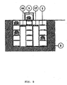
- Fig. 5 shows a cross section through the transfer room entrance 3 and the parking levels of a parking garage according to Fig. 4 , Two displacement units 16 and 17 are arranged in alignment to the left and right of the transfer room entrance 3.
- the vehicle 1 passes an induction loop 4 (see Fig. 1 ), whereby the entrance gate 2 opens and the vehicle on the pallet 5 in the middle of the transfer room entrance 3 can be parked.
- the driver and possibly other occupants leave the transfer room entrance 3 through the entrance person lock 6 and get to the pedestrian zone 7.
- the parking terminal 8 By operating the parking terminal 8, the movement of the vehicle 1 is initiated in a parking sector.
- the pallet 5 see Fig. 5
- a blank pallet can be pushed from the left or right to the lowering / lifting system. From the displacement unit 16 or 17, the vehicle is lowered or raised as needed and spent in a park sector.
- the driver actuates the parking terminal 10.
- the vehicle 1 is pushed together with the pallet on which it stands out of its parking sector by means of the displacement unit 16 or 17 on the lowering / lifting system and simultaneously moves the displacement unit 16 or 17 the Empty pallet located on the lowering / lifting system.
- the vehicle 1 is raised or lowered together with the pallet on which it stands in the transfer area exit 11.
- the exit passenger lock 9 opens or can be opened by the driver. With the opening of the exit locker 9 or in dependence thereon, optionally with a certain time interval, the exit gate opens 12. The driver and possibly other passengers can thus together with the vehicle 1 through the exit gate 12 from the transfer room exit 11th drive out.
Landscapes
- Engineering & Computer Science (AREA)
- Architecture (AREA)
- Mechanical Engineering (AREA)
- Civil Engineering (AREA)
- Structural Engineering (AREA)
- Power-Operated Mechanisms For Wings (AREA)
- Traffic Control Systems (AREA)
Description
Die Erfindung betrifft eine Parkvorrichtung für Fahrzeuge, insbesondere eine Parkvorrichtung für Personenkraftwagen, gemäß dem Oberbegriff des Patentanspruchs 1.The invention relates to a parking device for vehicles, in particular a parking device for passenger cars, according to the preamble of patent claim 1.
Insbesondere in den Ballungszentren der Städte, aber auch in eng besiedelten sonstigen Wohngebieten werden mehr und mehr Tiefgaragen und Hochgaragen gebaut, um ausreichend Parkmöglichkeiten bereitzustellen. Bei solchen Parkgaragen, die von dem Fahrer des Fahrzeugs selbst befahren werden, sind systembedingt die Suche nach einem freien Garagenplatz, lange Gehwege vom Fahrzeug bis zum Ausgang, ein hoher Benzinverbrauch, verbunden mit hohen Abgasemissionswerten bei der Suche eines freien Parkplatzes im Parkhaus, oftmals schwieriges Rangieren, um mit immer größer werdenden Fahrzeugen in relativ enge Parknischen einzuparken, entsprechende Platzangst der Nutzer, subjektives Unwohlsein der Nutzer durch schlechte Luft, dunkle Gänge und Treppenhäuser sowie durch sich kreuzende Fuß- und Fahrwege verursachte Gefahren systembedingte Nachteile. Weitere Systemnachteile sind Diebstahl, Vandalismus und insbesondere bei Frauen und älteren Leuten sowie zu späten Abendstunden ein Unwohlsein, dem nur unzulänglich dadurch Rechnung getragen werden kam, dass so genannte Frauenparkplätze in der Nähe des Ausgangs bereitgestellt werden. Hinzu kommt bei derartigen befahrbaren Parkhäusern eine systembedingt schlechte Nutzung der zur Verfügung stehenden Fläche und des zur Verfügung stehenden Raumes.In particular in the conurbations of the cities, but also in densely populated other residential areas more and more underground garages and garages are built to provide sufficient parking. In such parking garages, which are driven by the driver of the vehicle itself, are systemic the search for a free garage space, long walkways from the vehicle to the exit, high gasoline consumption, combined with high exhaust emission levels in the search for a free parking in the parking garage, often difficult Maneuvering to park with ever-larger vehicles in relatively narrow parking niches, corresponding fear of users, subjective malaise of the user due to bad air, dark corridors and stairwells as well as intersecting footpaths and lanes caused systemic disadvantages. Other system disadvantages are theft, vandalism and, especially in the case of women and older people, as well as in the late evening hours a discomfort, which was inadequately taken into account by providing so-called women's parking near the exit. In addition, in such passable car parks a systemic poor use of the available space and the available space.
Auf Grund der vorstehend genannten Nachteile sind in der Vergangenheit mehr und mehr automatische Parkvorrichtungen vorgeschlagen worden und zum Einsatz gekommen. Automatische Parkvorrichtungen bieten den grundsätzlichen Vorteil, dass die zur Verfügung stehende Fläche und das zur Verfügung stehende Bauvolumen besser für die Einlagerung von Fahrzeugen genutzt werden kann. Die
Diese bekannte automatische Parkvorrichtung überwindet zahlreiche der zuvor genannten Nachteile des sonstigen Standes der Technik. Sie weist jedoch weiterhin den Nachteil auf, dass die Fußwege und Fahrwege zur Parkvorrichtung einander kreuzen.This known automatic parking device overcomes many of the aforementioned disadvantages of the prior art. However, it still has the disadvantage that the footpaths and routes to the parking device cross each other.
Um eine derartige Kreuzung von Fußwegen und Fahrwegen zu vermeiden schlägt die
Der Erfindung liegt die Aufgabe zur Grunde, eine automatische Parkvorrichtung für Fahrzeuge bereitzustellen, bei der mögliche Behinderungen von Fußgängern und Fahrzeugen bestmöglich verhindert werden.The object of the invention is to provide an automatic parking device for vehicles in which possible obstructions of pedestrians and vehicles are best prevented.
Zur Lösung dieser Erfindung wird eine Parkvorrichtung für Fahrzeuge vorgeschlagen, bei der das Ein- und Ausparken so durchgeführt werden kann, dass Kreuzungsfreiheit zwischen den Fuß- und Fahrwegen besteht.To solve this invention, a parking device for vehicles is proposed, in which the parking and Ausparken can be performed so that there is no crossing between the foot and roads.
Erfindungsgemäß wird hierzu eine Parkvorrichtung für Fahrzeuge gemäß dem Patentanspruch 1 vorgeschlagen.According to the invention, a parking device for vehicles according to claim 1 is proposed for this purpose.
Die Bereitstellung von zwei separaten Übergaberäumen, d.h. einem Übergaberaum Einfahrt und einem Übergaberaum Ausfahrt, wobei zwischen den beiden Übergaberäumen eine durch entsprechende Personenschleusen erreichbare Fußgängerzone verläuft, verhindert, dass Fußverkehr und Fahrverkehr einander beeinträchtigen.The provision of two separate transfer rooms, ie a transfer room entrance and a transfer room exit, whereby between the two transfer rooms a pedestrian zone which can be reached by appropriate person locks, prevents pedestrian traffic and traffic from interfering with each other.
Ferner können die Einfahrtpersonenschleuse und die Ausfahrtpersonenschleuse jederzeit vom Inneren der jeweiligen Übergaberäume aus geöffnet werden. Hierdurch wird sichergestellt, dass, sollte sich doch noch eine Person unbeabsichtigter Weise in einem der Übergaberäumen befinden, diese jederzeit von sich aus von Innen die Personenschleuse öffnen und den Übergaberaum verlassen kann.Furthermore, the entrance person lock and the exit lock can be opened at any time from the inside of the respective transfer rooms. This ensures that, if a person is unintentionally located in one of the transfer rooms, they can at any time from the inside open the security gate and leave the transfer room.
In einer bevorzugten Ausführungsform kann ein Einfahrweg vorgesehen sein, der sich an das Einfahrttor anschließt und über den das Fahrzeug in den Übergaberaum Einfahrt eingefahren werden kann, sowie ein Ausfahrweg, der sich an das Ausfahrttor anschließt und auf den das Fahrzeug aus dem Übergaberaum Ausfahrt herausgefahren werden kann, wobei die Fußgängerzone, der Einfahrweg und der Ausfahrweg kreuzungsfrei zueinander verlaufen.In a preferred embodiment, a Einfahrweg may be provided, which adjoins the entrance gate and over which the vehicle can be retracted in the transfer room entrance, and a Ausfahrweg, which adjoins the exit gate and on which the vehicle from the transfer area exit are driven out can, with the pedestrian area, the Einfahrweg and Ausfahrweg crossing each other.
Vorzugsweise sind in dem Übergaberaum Einfahrt Hilfsmittel vorgesehen, die dem Fahrer ein exaktes Abstellen des Fahrzeugs auf einer Soll-Position erleichtern.Preferably, aids are provided in the transfer area, which facilitate the driver an exact parking of the vehicle at a desired position.
Die Innenabmessungen der Übergaberäume sind vorzugsweise so bemessen, dass alle Türen des Fahrzeugs geöffnet werden und die Insassen des Fahrzeugs in den Übergaberäumen ein- und aussteigen können. Auf diese Weise wird vermieden, dass Fahrgäste bereits vor dem Übergaberaum Einfahrt aussteigen müssen und somit unter Umständen auf anderen Wegen als der besonders sicher ausgeführten Fußgängerzone die Parkvorrichtung verlassen. Es versteht sich, dass die Übergaberäume entsprechend barrierefrei, behindertengerecht und freundlich ausgestattet und hell erleuchtet sind.The internal dimensions of the transfer spaces are preferably such that all the doors of the vehicle can be opened and the occupants of the vehicle can get in and out of the transfer rooms. In this way, it is avoided that passengers have to get off the entryway before the transfer room, and thus may leave the parking facility in other ways than the pedestrian zone, which is particularly safe. It is understood that the transfer rooms are barrier-free, handicapped accessible and friendly equipped and brightly lit.
In dem Übergaberaum Einfahrt ist vorzugsweise eine Überwachungseinrichtung vorgesehen, die die Anwesenheit von Personen in dem Übergaberaum Einfahrt detektiert. Die Steuereinrichtung ist hierbei vorzugsweise so ausgeführt, dass das automatische Verbringen des Fahrzeugs von dem Übergaberaum Einfahrt in einen Parksektor nur dann ausgelöst werden kann, wenn die Überwachungseinrichtung keine Anwesenheit von Personen in dem Übergaberaum Einfahrt detektiert. Hierdurch wird verhindert, dass Personen, die sich noch in dem Übergaberaum Einfahrt befinden, beim Verbringen des Fahrzeugs von dem Übergaberaum Einfahrt in einen Parksektor gefährdet werden. Die Überwachungseinrichtung umfasst hierzu vorzugsweise einen Bewegungsmelder.In the transfer room entrance, a monitoring device is preferably provided, which detects the presence of persons in the transfer room entrance. In this case, the control device is preferably embodied such that the automatic movement of the vehicle from the transfer area into a parking sector can only be triggered if the monitoring device does not detect the presence of persons in the transfer area entrance. This prevents people who are still in the transfer room entrance are endangered when moving the vehicle from the transfer room entrance to a parking sector. For this purpose, the monitoring device preferably comprises a motion detector.
In der Nähe des Übergaberaums Einfahrt, insbesondere in der Nähe der Einfahrtpersonenschleuse ist vorzugsweise ein Einparkterminal vorgesehen, über das der Benutzer das Verbringen seines in dem Übergaberaum Einfahrt abgestellten Fahrzeugs von dem Übergaberaum Einfahrt in einen Parksektor einleiten kann.In the vicinity of the transfer room entrance, in particular in the vicinity of the entrance person lock, a parking terminal is preferably provided, via which the user can initiate the movement of his parked vehicle in the transfer room entrance from the transfer room entrance into a parking sector.
In der Nähe des Übergaberaums Ausfahrt, insbesondere in der Nähe der Ausfahrtpersonenschleuse, ist vorzugsweise ein Ausparkterminal vorgesehen, über das der Benutzer das Verbringen seines Fahrzeugs von einem Parksektor in den Übergaberaum Ausfahrt einleiten kann.In the vicinity of the transfer area exit, in particular in the vicinity of the exit gate, a Ausparkterminal is preferably provided, via which the user can initiate the removal of his vehicle from a parking sector in the transfer area exit.
Die Steuereinrichtung lässt vorzugsweise ein Öffnen der Ausfahrtpersonenschleuse erst dann zu, wenn sich das Fahrzeug ausfahrbereit in dem Übergaberaum Ausfahrt befindet. Auch dies dient dazu, eine Gefährdung von Personen bei der automatischen Bewegung des Fahrzeugs zu verhindern.The control device preferably permits opening of the exit passenger lock only when the vehicle is ready for departure in the transfer area exit. This also serves to prevent a hazard to persons in the automatic movement of the vehicle.
Vorzugsweise bewirkt die Steuereinrichtung ein automatisches Schließen des Ausfahrttores, sobald das Fahrzeug den Übergaberaum Ausfahrt verlassen hat.Preferably, the controller causes an automatic closing of the exit gate as soon as the vehicle has left the transfer room exit.
Sobald das Ausfahrttor geschlossen ist, kann das nächste Fahrzeug in den Übergaberaum Ausfahrt verbracht werden.Once the exit gate is closed, the next vehicle can be transferred to the transfer room exit.
Die Erfindung wird im Folgenden anhand eines bevorzugten Ausführungsbeispiels unter Bezug auf die Zeichnungen näher erläutert, in der
-
Fig. 1 eine schematische Draufsicht auf einen Übergaberaum Einfahrt und einen Übergaberaum Ausfahrt sowie eine dazwischen angeordnete Fußgängerzone zeigt. -
Fig. 2 eine schematische Schnittdarstellung durch einen Übergaberaum zeigt, -
Fig. 3 einen Längsschnitt durch eine Hochgarage zeigt, -
Fig. 4 einen Längsschnitt durch eine Tiefgarage zeigt und -
Fig. 5 einen Querschnitt durch eine Tiefgarage und einen Übergaberaum Einfahrt zeigt.
-
Fig. 1 a schematic plan view of a transfer room entrance and a transfer room exit and a pedestrian zone arranged therebetween shows. -
Fig. 2 shows a schematic sectional view through a transfer room, -
Fig. 3 a longitudinal section through a high garage shows -
Fig. 4 a longitudinal section through an underground car park shows and -
Fig. 5 a cross section through an underground car park and a transfer room entrance shows.
Ein derartiger Personenkraftwagen ist mit dem Bezugszeichen 1 gekennzeichnet. Er steht in Fahrtrichtung vor einem Übergaberaum Einfahrt 3, in welchen er nach Überfahren einer Induktionsschleife 4 durch ein Einfahrttor 2 auf eine Palette 5 gefahren werden kann. Nachdem das Fahrzeug 1 seine Soll- Position auf der Palette 5 erreicht hat, wozu ihm entsprechende Hilfsvorrichtungen, beispielsweise in Form von Scannern, Bewegungsmeldern, Waagen und Videoeinrichtungen zur Verfügung stehen, schließt das Einfahrttor 2 selbsttätig. Zur Steuerung dieser und anderer automatischer Funktionen der Parkvorrichtung ist eine Steuereinrichtung (nicht gezeigt) vorgesehen.Such a passenger car is marked with the reference numeral 1. He stands in the direction of travel in front of a
Nachdem das Fahrzeug seine Soll-Position erreicht hat, können der Fahrer sowie eventuelle weitere Insassen das Fahrzeug zu beiden Seiten hin verlassen und durch eine Einfahrtpersonenschleuse 6, welche sich an der dem Einfahrttor 2 gegenüberliegenden Stirnseite des Übergaberaums Einfahrt befindet, verlassen, wodurch sie in eine Fußgängerzone 7 gelangen. Es versteht sich, dass die Einfahrtpersonenschleuse 6 auch an anderen Stellen des Übergaberaums Einfahrt 3 angeordnet sein kann.After the vehicle has reached its desired position, the driver and any other occupants can leave the vehicle on both sides and leave through a Einfahrpersonenschleuse 6, which is located at the
Auf der anderen Seite der Fußgängerzone 7, dem Übergaberaum Einfahrt 3 gegenüberliegend, ist ein Übergaberaum Ausfahrt 11 angeordnet. Dieser ist im Wesentlichen symmetrisch zum Übergaberaum Einfahrt 3 ausgeführt. Er verfügt über eine Ausfahrtpersonenschleuse 9, über die Personen von der Fußgängerzone 7 aus in den Übergaberaum Ausfahrt 11 hineingehen können. Dort können sie von beiden Seiten in ein dorthin bereits automatisch verbrachtes Fahrzeug einsteigen und durch ein Ausfahrttor 12 herausfahren. Es versteht sich, dass auch in diesem Fall die Ausfahrtpersonenschleuse 9 an anderen Stellen angeordnet sein kann.On the other side of the
In der Nähe der Einfahrtpersonenschleuse 6 ist ein Einparkterminal 8 vorgesehen. Ein Ausparkterminal 10 befindet sich in der Nähe der Ausfahrtpersonenschleuse 9.In the vicinity of the entrance person lock 6 a parking terminal 8 is provided. An
Es versteht sich für den Fachmann, dass bei einem überirdisch angeordneten Parkhaus die Palette mit dem darauf befindlichen Fahrzeug nach oben angehoben würde.It is understood by those skilled in the art that in an above-ground parking garage, the pallet would be raised with the vehicle thereon up.
Die Verbringung von Fahrzeugen in einem automatischen Parksystem mit Paletten ist dem Fachmann bekannt. Sie ist insbesondere in der
Es versteht sich für den Fachmann, dass die erfindungsgemäße Anordnung der Übergaberäume und Fußgängerzone bei einer beliebigen Ausführungsart des automatischen Fahrzeugtransportes im Parkhaus selbst anwendbar ist.It is understood by those skilled in the art that the inventive arrangement of the transfer rooms and pedestrian zone in any embodiment of the automatic vehicle transport in the parking garage itself is applicable.
Es versteht sich, dass die erfindungsgemäße Parkvorrichtung für Fahrzeuge auch verwendet werden kann bei einem Parkhaus, bei dem sowohl überirdisch als auch unterirdisch Parksektoren angeordnet sind.It is understood that the parking device according to the invention for vehicles can also be used in a parking garage in which parking sectors are arranged both above ground and underground.
Der Vorgang des Einparkens und Ausparkens gestaltet sich wie folgt:The process of parking and parking is as follows:
Wie zuvor beschrieben, überfahrt das Fahrzeug 1 eine Induktionsschleife 4 (siehe
Zum Abholen des Fahrzeugs betätigt der Fahrer den Ausparkterminal 10. Das Fahrzeug 1 wird zusammen mit der Palette, auf der es steht, aus seinem Parksektor mittels der Verschiebeeinheit 16 oder 17 auf die Absenk-/Hebeanlage geschoben und gleichzeitig zieht die Verschiebeeinheit 16 oder 17 die auf der Absenk-/Hebeanlage befindliche Leerpalette. Anschließend wird das Fahrzeug 1 zusammen mit der Palette, auf der es steht, in den Übergaberaum Ausfahrt 11 gehoben oder gesenkt. Sobald es dort seine Endposition erreicht hat, öffnet sich die Ausfahrtpersonenschleuse 9 bzw. kann durch den Fahrer geöffnet werden. Mit dem Öffnen der Ausfahrtpersonenschleuse 9 bzw. in Abhängigkeit hiervon, gegebenenfalls mit einem gewissen zeitlichen Abstand hierzu, öffnet sich auch das Ausfahrttor 12. Der Fahrer und die gegebenenfalls weiteren Fahrgäste können somit zusammen mit dem Fahrzeug 1 durch das Ausfahrttor 12 aus dem Übergaberaum Ausfahrt 11 herausfahren.To pick up the vehicle, the driver actuates the
Es versteht sich, dass mehrere der vorstehend skizzierten Parkvorrichtungen zusammen innerhalb eines Parkhauses angeordnet sein können. Insbesondere können mehrere der Parkhäuser gemäß
Claims (10)
- A parking device for vehicles with a handover area entrance (3), which has an entrance gate (2) through which a vehicle (1) can be driven in by a driver into the handover area entrance (3), and a person entrance lock (6), through which the driver can leave the handover area entrance (3),
with a handover area exit (11), which has an exit gate (12) through which a vehicle (1) can be driven out by a driver from the handover area exit (11), and a persons' exit lock (9), through which the driver can enter the handover area exit (11),
with a control device for the controlling of functions of the parking device and
with a transport arrangement for automatically bringing the vehicle (1) from the handover area entrance (3) into a parking sector and from a parking sector into the handover area exit (11),
wherein the person locks (6, 9) lead to a pedestrian zone (7) which runs through between the handover areas (3, 11), characterized in that the person entrance lock (6) and the person exit lock (9) can be opened at any time from the interior of the handover areas (3, 11). - The parking device according to Claim 1, characterized in that
an entry lane is provided, which adjoins the entrance gate (2) and via which the vehicle (1) can be driven into the handover area entrance (3),
an exit lane is provided, which adjoins the exit gate (12) and onto which the vehicle can be driven out from the handover area exit (11), and
the pedestrian zone (7), the entry lane and the exit lane run free of intersection with respect to each other. - The parking device according to one of the preceding claims, characterized in that in the handover area entrance (3) assistance means are provided which facilitate for the driver a precise parking of the vehicle (1) in a required position.
- The parking device according to one of the preceding claims, characterized in that the interior dimensions of the handover areas (3, 11) are dimensioned so that all the doors of the vehicle (1) can be opened and the occupants of the vehicle (1) can step into and from the handover areas (3, 11).
- The parking device according to one of the preceding claims, characterized in that in the handover area entrance (3) a monitoring arrangement is provided, which detects the presence of persons in the handover area entrance (3), and that the control arrangement can only activate the bringing of the vehicle (1) from the handover area entrance (3) into a parking sector when the monitoring arrangement is not detecting the presence of persons in the handover area entrance (3).
- The parking device according to Claim 5, characterized in that the monitoring arrangement comprises a motion sensor.
- The parking device according to one of the preceding claims, characterized in that a parking terminal (8) is provided, via which the user can initiate the bringing of his vehicle (1), which is parked in the handover area entrance (3), from the handover area entrance (3) into a parking sector.
- The parking device according to one of the preceding claims, characterized in that a retrieval terminal (10) is provided, via which the user can initiate the bringing of his vehicle (1) from a parking sector into a handover area exit (11).
- The parking device according to one of the preceding claims, characterized in that the control arrangement only permits an opening of the person exit lock (9) when the vehicle (1) is situated, ready for driving out, in the handover area exit (11).
- The parking device according to one of the preceding claims, characterized in that the control arrangement brings about an automatic closing of the exit gate (12) as soon as the vehicle (1) has left the handover area exit (11).
Applications Claiming Priority (1)
| Application Number | Priority Date | Filing Date | Title |
|---|---|---|---|
| DE200710023948 DE102007023948A1 (en) | 2007-05-23 | 2007-05-23 | Parking device for vehicles |
Publications (3)
| Publication Number | Publication Date |
|---|---|
| EP2003269A2 EP2003269A2 (en) | 2008-12-17 |
| EP2003269A3 EP2003269A3 (en) | 2008-12-31 |
| EP2003269B1 true EP2003269B1 (en) | 2013-01-09 |
Family
ID=39877069
Family Applications (1)
| Application Number | Title | Priority Date | Filing Date |
|---|---|---|---|
| EP20080009455 Active EP2003269B1 (en) | 2007-05-23 | 2008-05-23 | Parking device for vehicles |
Country Status (2)
| Country | Link |
|---|---|
| EP (1) | EP2003269B1 (en) |
| DE (1) | DE102007023948A1 (en) |
Family Cites Families (9)
| Publication number | Priority date | Publication date | Assignee | Title |
|---|---|---|---|---|
| JPH066834B2 (en) * | 1984-07-31 | 1994-01-26 | 株式会社日立製作所 | Multistory parking lot |
| DE4042646C2 (en) | 1990-04-06 | 1999-01-07 | Paul Meyer | Multi-storey car park |
| DE4023988C2 (en) | 1990-07-28 | 1997-02-13 | Ideal Standard | Sanitary fitting |
| DE4340617C2 (en) * | 1993-11-29 | 2003-04-03 | Bayerische Motoren Werke Ag | Motor vehicle parking garage for a Park & Ride station |
| DE59408734D1 (en) * | 1994-04-02 | 1999-10-14 | Rita Reuss | GARAGE FOR PASSENGER VEHICLES |
| DE29613766U1 (en) * | 1996-08-09 | 1996-10-02 | Apg Autopark Garagenmanagement | Parking system for motor vehicles |
| DE19738389A1 (en) * | 1997-09-03 | 1999-03-25 | Mansfeld Maschinen Und Anlagen | Underground garage or car park for e.g. residential and/or business parking |
| DE19741638A1 (en) * | 1997-09-22 | 1999-04-01 | Fraunhofer Ges Forschung | Automatic vehicle parking system |
| DE10021001A1 (en) * | 2000-04-29 | 2001-10-31 | Krups Parking Systems Gmbh & C | Multi storey garage for selling and repairing cars, has display area on ground floor, storage area on bottom or top floor, and repair area or offices above ground floor |
-
2007
- 2007-05-23 DE DE200710023948 patent/DE102007023948A1/en not_active Withdrawn
-
2008
- 2008-05-23 EP EP20080009455 patent/EP2003269B1/en active Active
Also Published As
| Publication number | Publication date |
|---|---|
| EP2003269A3 (en) | 2008-12-31 |
| EP2003269A2 (en) | 2008-12-17 |
| DE102007023948A1 (en) | 2008-11-27 |
Similar Documents
| Publication | Publication Date | Title |
|---|---|---|
| WO2014198579A1 (en) | Protective wall for protecting persons from travelling rail vehicles | |
| EP3196385A1 (en) | Car park for vehicles, in particular multi-storey car park, and method for the production of a car park | |
| DE202011003734U1 (en) | Compact park | |
| WO2003018936A1 (en) | Building and parking system | |
| DE102007007599A1 (en) | Loading device and method for transport goods | |
| AT509870B1 (en) | ARRANGEMENT FOR DIRECTION-ORIENTED ALIGNMENT OF MULTILAYER MOTOR VEHICLES ON PARKING SPACES OR IN GARAGES | |
| EP2003269B1 (en) | Parking device for vehicles | |
| DE10110871A1 (en) | Fully automatic multi-level car park has parking areas concerted by tracks with stator elements controlled to generate moving magnetic field that interacts with magnets on pallets | |
| DE2541834A1 (en) | Multi storey car park building - is circular structure with concentric telescopically linked spiral rams crossing parking areas | |
| EP1614834B1 (en) | Shelf storage facility for automobiles | |
| DE3917475A1 (en) | Parking robot for high density car park - is controlled by processor to park and remove vehicles from successive parking planes | |
| DE102014008237A1 (en) | Parking device and control device | |
| DE102005007475B3 (en) | Person e.g. handicapped person, elevator for use in building, has telescopic unit that is extensible from upper storey to underlying storey, and safety limit switches provided in platform, cover plate, cabine or door | |
| DE2434371A1 (en) | PROCEDURE AND EQUIPMENT FOR PARKING A CAR IN A PARKING LOT, IN PARTICULAR IN A CAR PARK | |
| WO1992006261A1 (en) | Covered car park unit | |
| CH635395A5 (en) | Double-storey garage | |
| DE1684725A1 (en) | Retractable multi-storey car park garage | |
| DE10151916A1 (en) | Space-saving vehicle parking system comprises drive-on parking surface fixedly connected to movable unit which can then be moved horizontally and/or vertically for compact parking | |
| WO2018007114A1 (en) | Concept for reducing electrical energy consumption of a car park | |
| DE1759343A1 (en) | Garage for several vehicles | |
| DE19738389A1 (en) | Underground garage or car park for e.g. residential and/or business parking | |
| WO1999060231A1 (en) | Car park | |
| DE2302145B2 (en) | Facility for a multiple garage | |
| DE2753290A1 (en) | Two floor monolithic garage construction - is built of reinforced concrete with one floor lowerable hydraulically into line service pit | |
| WO1994006662A1 (en) | Device for ensuring the safe crossing of a traffic road by a pedestrian |
Legal Events
| Date | Code | Title | Description |
|---|---|---|---|
| PUAI | Public reference made under article 153(3) epc to a published international application that has entered the european phase |
Free format text: ORIGINAL CODE: 0009012 |
|
| PUAL | Search report despatched |
Free format text: ORIGINAL CODE: 0009013 |
|
| AK | Designated contracting states |
Kind code of ref document: A2 Designated state(s): AT BE BG CH CY CZ DE DK EE ES FI FR GB GR HR HU IE IS IT LI LT LU LV MC MT NL NO PL PT RO SE SI SK TR |
|
| AX | Request for extension of the european patent |
Extension state: AL BA MK RS |
|
| AK | Designated contracting states |
Kind code of ref document: A3 Designated state(s): AT BE BG CH CY CZ DE DK EE ES FI FR GB GR HR HU IE IS IT LI LT LU LV MC MT NL NO PL PT RO SE SI SK TR |
|
| AX | Request for extension of the european patent |
Extension state: AL BA MK RS |
|
| 17P | Request for examination filed |
Effective date: 20090626 |
|
| AKX | Designation fees paid |
Designated state(s): AT BE BG CH CY CZ DE DK EE ES FI FR GB GR HR HU IE IS IT LI LT LU LV MC MT NL NO PL PT RO SE SI SK TR |
|
| GRAP | Despatch of communication of intention to grant a patent |
Free format text: ORIGINAL CODE: EPIDOSNIGR1 |
|
| GRAS | Grant fee paid |
Free format text: ORIGINAL CODE: EPIDOSNIGR3 |
|
| GRAA | (expected) grant |
Free format text: ORIGINAL CODE: 0009210 |
|
| AK | Designated contracting states |
Kind code of ref document: B1 Designated state(s): AT BE BG CH CY CZ DE DK EE ES FI FR GB GR HR HU IE IS IT LI LT LU LV MC MT NL NO PL PT RO SE SI SK TR |
|
| REG | Reference to a national code |
Ref country code: GB Ref legal event code: FG4D Free format text: NOT ENGLISH |
|
| REG | Reference to a national code |
Ref country code: CH Ref legal event code: EP Ref country code: AT Ref legal event code: REF Ref document number: 592862 Country of ref document: AT Kind code of ref document: T Effective date: 20130115 |
|
| REG | Reference to a national code |
Ref country code: IE Ref legal event code: FG4D Free format text: LANGUAGE OF EP DOCUMENT: GERMAN |
|
| REG | Reference to a national code |
Ref country code: DE Ref legal event code: R096 Ref document number: 502008009044 Country of ref document: DE Effective date: 20130307 |
|
| PG25 | Lapsed in a contracting state [announced via postgrant information from national office to epo] |
Ref country code: SI Free format text: LAPSE BECAUSE OF FAILURE TO SUBMIT A TRANSLATION OF THE DESCRIPTION OR TO PAY THE FEE WITHIN THE PRESCRIBED TIME-LIMIT Effective date: 20130109 |
|
| REG | Reference to a national code |
Ref country code: NL Ref legal event code: VDEP Effective date: 20130109 |
|
| REG | Reference to a national code |
Ref country code: LT Ref legal event code: MG4D |
|
| PG25 | Lapsed in a contracting state [announced via postgrant information from national office to epo] |
Ref country code: NO Free format text: LAPSE BECAUSE OF FAILURE TO SUBMIT A TRANSLATION OF THE DESCRIPTION OR TO PAY THE FEE WITHIN THE PRESCRIBED TIME-LIMIT Effective date: 20130409 Ref country code: IS Free format text: LAPSE BECAUSE OF FAILURE TO SUBMIT A TRANSLATION OF THE DESCRIPTION OR TO PAY THE FEE WITHIN THE PRESCRIBED TIME-LIMIT Effective date: 20130509 Ref country code: ES Free format text: LAPSE BECAUSE OF FAILURE TO SUBMIT A TRANSLATION OF THE DESCRIPTION OR TO PAY THE FEE WITHIN THE PRESCRIBED TIME-LIMIT Effective date: 20130420 Ref country code: BG Free format text: LAPSE BECAUSE OF FAILURE TO SUBMIT A TRANSLATION OF THE DESCRIPTION OR TO PAY THE FEE WITHIN THE PRESCRIBED TIME-LIMIT Effective date: 20130409 Ref country code: LT Free format text: LAPSE BECAUSE OF FAILURE TO SUBMIT A TRANSLATION OF THE DESCRIPTION OR TO PAY THE FEE WITHIN THE PRESCRIBED TIME-LIMIT Effective date: 20130109 Ref country code: SE Free format text: LAPSE BECAUSE OF FAILURE TO SUBMIT A TRANSLATION OF THE DESCRIPTION OR TO PAY THE FEE WITHIN THE PRESCRIBED TIME-LIMIT Effective date: 20130109 |
|
| PG25 | Lapsed in a contracting state [announced via postgrant information from national office to epo] |
Ref country code: NL Free format text: LAPSE BECAUSE OF FAILURE TO SUBMIT A TRANSLATION OF THE DESCRIPTION OR TO PAY THE FEE WITHIN THE PRESCRIBED TIME-LIMIT Effective date: 20130109 Ref country code: LV Free format text: LAPSE BECAUSE OF FAILURE TO SUBMIT A TRANSLATION OF THE DESCRIPTION OR TO PAY THE FEE WITHIN THE PRESCRIBED TIME-LIMIT Effective date: 20130109 Ref country code: PT Free format text: LAPSE BECAUSE OF FAILURE TO SUBMIT A TRANSLATION OF THE DESCRIPTION OR TO PAY THE FEE WITHIN THE PRESCRIBED TIME-LIMIT Effective date: 20130509 Ref country code: GR Free format text: LAPSE BECAUSE OF FAILURE TO SUBMIT A TRANSLATION OF THE DESCRIPTION OR TO PAY THE FEE WITHIN THE PRESCRIBED TIME-LIMIT Effective date: 20130410 Ref country code: PL Free format text: LAPSE BECAUSE OF FAILURE TO SUBMIT A TRANSLATION OF THE DESCRIPTION OR TO PAY THE FEE WITHIN THE PRESCRIBED TIME-LIMIT Effective date: 20130109 Ref country code: FI Free format text: LAPSE BECAUSE OF FAILURE TO SUBMIT A TRANSLATION OF THE DESCRIPTION OR TO PAY THE FEE WITHIN THE PRESCRIBED TIME-LIMIT Effective date: 20130109 |
|
| PG25 | Lapsed in a contracting state [announced via postgrant information from national office to epo] |
Ref country code: HR Free format text: LAPSE BECAUSE OF FAILURE TO SUBMIT A TRANSLATION OF THE DESCRIPTION OR TO PAY THE FEE WITHIN THE PRESCRIBED TIME-LIMIT Effective date: 20130109 |
|
| PG25 | Lapsed in a contracting state [announced via postgrant information from national office to epo] |
Ref country code: RO Free format text: LAPSE BECAUSE OF FAILURE TO SUBMIT A TRANSLATION OF THE DESCRIPTION OR TO PAY THE FEE WITHIN THE PRESCRIBED TIME-LIMIT Effective date: 20130109 Ref country code: EE Free format text: LAPSE BECAUSE OF FAILURE TO SUBMIT A TRANSLATION OF THE DESCRIPTION OR TO PAY THE FEE WITHIN THE PRESCRIBED TIME-LIMIT Effective date: 20130109 Ref country code: DK Free format text: LAPSE BECAUSE OF FAILURE TO SUBMIT A TRANSLATION OF THE DESCRIPTION OR TO PAY THE FEE WITHIN THE PRESCRIBED TIME-LIMIT Effective date: 20130109 Ref country code: SK Free format text: LAPSE BECAUSE OF FAILURE TO SUBMIT A TRANSLATION OF THE DESCRIPTION OR TO PAY THE FEE WITHIN THE PRESCRIBED TIME-LIMIT Effective date: 20130109 Ref country code: CZ Free format text: LAPSE BECAUSE OF FAILURE TO SUBMIT A TRANSLATION OF THE DESCRIPTION OR TO PAY THE FEE WITHIN THE PRESCRIBED TIME-LIMIT Effective date: 20130109 |
|
| PLBE | No opposition filed within time limit |
Free format text: ORIGINAL CODE: 0009261 |
|
| STAA | Information on the status of an ep patent application or granted ep patent |
Free format text: STATUS: NO OPPOSITION FILED WITHIN TIME LIMIT |
|
| PG25 | Lapsed in a contracting state [announced via postgrant information from national office to epo] |
Ref country code: CY Free format text: LAPSE BECAUSE OF FAILURE TO SUBMIT A TRANSLATION OF THE DESCRIPTION OR TO PAY THE FEE WITHIN THE PRESCRIBED TIME-LIMIT Effective date: 20130109 |
|
| 26N | No opposition filed |
Effective date: 20131010 |
|
| PG25 | Lapsed in a contracting state [announced via postgrant information from national office to epo] |
Ref country code: IT Free format text: LAPSE BECAUSE OF FAILURE TO SUBMIT A TRANSLATION OF THE DESCRIPTION OR TO PAY THE FEE WITHIN THE PRESCRIBED TIME-LIMIT Effective date: 20130109 |
|
| REG | Reference to a national code |
Ref country code: DE Ref legal event code: R097 Ref document number: 502008009044 Country of ref document: DE Effective date: 20131010 |
|
| PGFP | Annual fee paid to national office [announced via postgrant information from national office to epo] |
Ref country code: IE Payment date: 20131129 Year of fee payment: 6 Ref country code: MC Payment date: 20131202 Year of fee payment: 6 |
|
| PGFP | Annual fee paid to national office [announced via postgrant information from national office to epo] |
Ref country code: BE Payment date: 20131129 Year of fee payment: 6 Ref country code: FR Payment date: 20131129 Year of fee payment: 6 Ref country code: LU Payment date: 20131202 Year of fee payment: 6 |
|
| PG25 | Lapsed in a contracting state [announced via postgrant information from national office to epo] |
Ref country code: LU Free format text: LAPSE BECAUSE OF NON-PAYMENT OF DUE FEES Effective date: 20140523 |
|
| REG | Reference to a national code |
Ref country code: CH Ref legal event code: PL Ref country code: CH Ref legal event code: AECN Free format text: DAS PATENT IST AUFGRUND DES WEITERBEHANDLUNGSANTRAGS VOM 09. DEZEMBER 2014 REAKTIVIERT WORDEN. |
|
| GBPC | Gb: european patent ceased through non-payment of renewal fee |
Effective date: 20140523 |
|
| PG25 | Lapsed in a contracting state [announced via postgrant information from national office to epo] |
Ref country code: MC Free format text: LAPSE BECAUSE OF NON-PAYMENT OF DUE FEES Effective date: 20140602 |
|
| REG | Reference to a national code |
Ref country code: GB Ref legal event code: S28 Free format text: APPLICATION FILED |
|
| REG | Reference to a national code |
Ref country code: IE Ref legal event code: MM4A |
|
| PG25 | Lapsed in a contracting state [announced via postgrant information from national office to epo] |
Ref country code: MT Free format text: LAPSE BECAUSE OF FAILURE TO SUBMIT A TRANSLATION OF THE DESCRIPTION OR TO PAY THE FEE WITHIN THE PRESCRIBED TIME-LIMIT Effective date: 20130109 |
|
| REG | Reference to a national code |
Ref country code: FR Ref legal event code: ST Effective date: 20150130 |
|
| REG | Reference to a national code |
Ref country code: GB Ref legal event code: S28 Free format text: RESTORATION ALLOWED Effective date: 20150327 |
|
| PG25 | Lapsed in a contracting state [announced via postgrant information from national office to epo] |
Ref country code: IE Free format text: LAPSE BECAUSE OF NON-PAYMENT OF DUE FEES Effective date: 20140523 |
|
| PG25 | Lapsed in a contracting state [announced via postgrant information from national office to epo] |
Ref country code: FR Free format text: LAPSE BECAUSE OF NON-PAYMENT OF DUE FEES Effective date: 20140602 Ref country code: GB Free format text: LAPSE BECAUSE OF NON-PAYMENT OF DUE FEES Effective date: 20140523 |
|
| PG25 | Lapsed in a contracting state [announced via postgrant information from national office to epo] |
Ref country code: TR Free format text: LAPSE BECAUSE OF FAILURE TO SUBMIT A TRANSLATION OF THE DESCRIPTION OR TO PAY THE FEE WITHIN THE PRESCRIBED TIME-LIMIT Effective date: 20130109 |
|
| PG25 | Lapsed in a contracting state [announced via postgrant information from national office to epo] |
Ref country code: HU Free format text: LAPSE BECAUSE OF FAILURE TO SUBMIT A TRANSLATION OF THE DESCRIPTION OR TO PAY THE FEE WITHIN THE PRESCRIBED TIME-LIMIT; INVALID AB INITIO Effective date: 20080523 |
|
| PG25 | Lapsed in a contracting state [announced via postgrant information from national office to epo] |
Ref country code: BE Free format text: LAPSE BECAUSE OF NON-PAYMENT OF DUE FEES Effective date: 20140531 |
|
| PGFP | Annual fee paid to national office [announced via postgrant information from national office to epo] |
Ref country code: GB Payment date: 20210511 Year of fee payment: 14 |
|
| PGFP | Annual fee paid to national office [announced via postgrant information from national office to epo] |
Ref country code: AT Payment date: 20220609 Year of fee payment: 15 |
|
| GBPC | Gb: european patent ceased through non-payment of renewal fee |
Effective date: 20220523 |
|
| REG | Reference to a national code |
Ref country code: AT Ref legal event code: MM01 Ref document number: 592862 Country of ref document: AT Kind code of ref document: T Effective date: 20220523 |
|
| PG25 | Lapsed in a contracting state [announced via postgrant information from national office to epo] |
Ref country code: AT Free format text: LAPSE BECAUSE OF NON-PAYMENT OF DUE FEES Effective date: 20220523 |
|
| PG25 | Lapsed in a contracting state [announced via postgrant information from national office to epo] |
Ref country code: GB Free format text: LAPSE BECAUSE OF NON-PAYMENT OF DUE FEES Effective date: 20220523 |
|
| PGFP | Annual fee paid to national office [announced via postgrant information from national office to epo] |
Ref country code: DE Payment date: 20230628 Year of fee payment: 16 Ref country code: CH Payment date: 20230602 Year of fee payment: 16 |