EP2000378B1 - Vehicle and motor controller for vehicle - Google Patents
Vehicle and motor controller for vehicle Download PDFInfo
- Publication number
- EP2000378B1 EP2000378B1 EP07738556.5A EP07738556A EP2000378B1 EP 2000378 B1 EP2000378 B1 EP 2000378B1 EP 07738556 A EP07738556 A EP 07738556A EP 2000378 B1 EP2000378 B1 EP 2000378B1
- Authority
- EP
- European Patent Office
- Prior art keywords
- torque
- motor
- engine
- cylinder
- expansion
- Prior art date
- Legal status (The legal status is an assumption and is not a legal conclusion. Google has not performed a legal analysis and makes no representation as to the accuracy of the status listed.)
- Not-in-force
Links
Images


Classifications
-
- B—PERFORMING OPERATIONS; TRANSPORTING
- B60—VEHICLES IN GENERAL
- B60K—ARRANGEMENT OR MOUNTING OF PROPULSION UNITS OR OF TRANSMISSIONS IN VEHICLES; ARRANGEMENT OR MOUNTING OF PLURAL DIVERSE PRIME-MOVERS IN VEHICLES; AUXILIARY DRIVES FOR VEHICLES; INSTRUMENTATION OR DASHBOARDS FOR VEHICLES; ARRANGEMENTS IN CONNECTION WITH COOLING, AIR INTAKE, GAS EXHAUST OR FUEL SUPPLY OF PROPULSION UNITS IN VEHICLES
- B60K6/00—Arrangement or mounting of plural diverse prime-movers for mutual or common propulsion, e.g. hybrid propulsion systems comprising electric motors and internal combustion engines ; Control systems therefor, i.e. systems controlling two or more prime movers, or controlling one of these prime movers and any of the transmission, drive or drive units Informative references: mechanical gearings with secondary electric drive F16H3/72; arrangements for handling mechanical energy structurally associated with the dynamo-electric machine H02K7/00; machines comprising structurally interrelated motor and generator parts H02K51/00; dynamo-electric machines not otherwise provided for in H02K see H02K99/00
- B60K6/20—Arrangement or mounting of plural diverse prime-movers for mutual or common propulsion, e.g. hybrid propulsion systems comprising electric motors and internal combustion engines ; Control systems therefor, i.e. systems controlling two or more prime movers, or controlling one of these prime movers and any of the transmission, drive or drive units Informative references: mechanical gearings with secondary electric drive F16H3/72; arrangements for handling mechanical energy structurally associated with the dynamo-electric machine H02K7/00; machines comprising structurally interrelated motor and generator parts H02K51/00; dynamo-electric machines not otherwise provided for in H02K see H02K99/00 the prime-movers consisting of electric motors and internal combustion engines, e.g. HEVs
- B60K6/42—Arrangement or mounting of plural diverse prime-movers for mutual or common propulsion, e.g. hybrid propulsion systems comprising electric motors and internal combustion engines ; Control systems therefor, i.e. systems controlling two or more prime movers, or controlling one of these prime movers and any of the transmission, drive or drive units Informative references: mechanical gearings with secondary electric drive F16H3/72; arrangements for handling mechanical energy structurally associated with the dynamo-electric machine H02K7/00; machines comprising structurally interrelated motor and generator parts H02K51/00; dynamo-electric machines not otherwise provided for in H02K see H02K99/00 the prime-movers consisting of electric motors and internal combustion engines, e.g. HEVs characterised by the architecture of the hybrid electric vehicle
- B60K6/48—Parallel type
- B60K6/485—Motor-assist type
-
- B—PERFORMING OPERATIONS; TRANSPORTING
- B60—VEHICLES IN GENERAL
- B60W—CONJOINT CONTROL OF VEHICLE SUB-UNITS OF DIFFERENT TYPE OR DIFFERENT FUNCTION; CONTROL SYSTEMS SPECIALLY ADAPTED FOR HYBRID VEHICLES; ROAD VEHICLE DRIVE CONTROL SYSTEMS FOR PURPOSES NOT RELATED TO THE CONTROL OF A PARTICULAR SUB-UNIT
- B60W20/00—Control systems specially adapted for hybrid vehicles
- B60W20/10—Controlling the power contribution of each of the prime movers to meet required power demand
-
- B—PERFORMING OPERATIONS; TRANSPORTING
- B60—VEHICLES IN GENERAL
- B60L—PROPULSION OF ELECTRICALLY-PROPELLED VEHICLES; SUPPLYING ELECTRIC POWER FOR AUXILIARY EQUIPMENT OF ELECTRICALLY-PROPELLED VEHICLES; ELECTRODYNAMIC BRAKE SYSTEMS FOR VEHICLES IN GENERAL; MAGNETIC SUSPENSION OR LEVITATION FOR VEHICLES; MONITORING OPERATING VARIABLES OF ELECTRICALLY-PROPELLED VEHICLES; ELECTRIC SAFETY DEVICES FOR ELECTRICALLY-PROPELLED VEHICLES
- B60L15/00—Methods, circuits, or devices for controlling the traction-motor speed of electrically-propelled vehicles
- B60L15/20—Methods, circuits, or devices for controlling the traction-motor speed of electrically-propelled vehicles for control of the vehicle or its driving motor to achieve a desired performance, e.g. speed, torque, programmed variation of speed
- B60L15/2009—Methods, circuits, or devices for controlling the traction-motor speed of electrically-propelled vehicles for control of the vehicle or its driving motor to achieve a desired performance, e.g. speed, torque, programmed variation of speed for braking
-
- B—PERFORMING OPERATIONS; TRANSPORTING
- B60—VEHICLES IN GENERAL
- B60L—PROPULSION OF ELECTRICALLY-PROPELLED VEHICLES; SUPPLYING ELECTRIC POWER FOR AUXILIARY EQUIPMENT OF ELECTRICALLY-PROPELLED VEHICLES; ELECTRODYNAMIC BRAKE SYSTEMS FOR VEHICLES IN GENERAL; MAGNETIC SUSPENSION OR LEVITATION FOR VEHICLES; MONITORING OPERATING VARIABLES OF ELECTRICALLY-PROPELLED VEHICLES; ELECTRIC SAFETY DEVICES FOR ELECTRICALLY-PROPELLED VEHICLES
- B60L3/00—Electric devices on electrically-propelled vehicles for safety purposes; Monitoring operating variables, e.g. speed, deceleration or energy consumption
- B60L3/0023—Detecting, eliminating, remedying or compensating for drive train abnormalities, e.g. failures within the drive train
- B60L3/0076—Detecting, eliminating, remedying or compensating for drive train abnormalities, e.g. failures within the drive train relating to braking
-
- B—PERFORMING OPERATIONS; TRANSPORTING
- B60—VEHICLES IN GENERAL
- B60L—PROPULSION OF ELECTRICALLY-PROPELLED VEHICLES; SUPPLYING ELECTRIC POWER FOR AUXILIARY EQUIPMENT OF ELECTRICALLY-PROPELLED VEHICLES; ELECTRODYNAMIC BRAKE SYSTEMS FOR VEHICLES IN GENERAL; MAGNETIC SUSPENSION OR LEVITATION FOR VEHICLES; MONITORING OPERATING VARIABLES OF ELECTRICALLY-PROPELLED VEHICLES; ELECTRIC SAFETY DEVICES FOR ELECTRICALLY-PROPELLED VEHICLES
- B60L3/00—Electric devices on electrically-propelled vehicles for safety purposes; Monitoring operating variables, e.g. speed, deceleration or energy consumption
- B60L3/10—Indicating wheel slip ; Correction of wheel slip
-
- B—PERFORMING OPERATIONS; TRANSPORTING
- B60—VEHICLES IN GENERAL
- B60L—PROPULSION OF ELECTRICALLY-PROPELLED VEHICLES; SUPPLYING ELECTRIC POWER FOR AUXILIARY EQUIPMENT OF ELECTRICALLY-PROPELLED VEHICLES; ELECTRODYNAMIC BRAKE SYSTEMS FOR VEHICLES IN GENERAL; MAGNETIC SUSPENSION OR LEVITATION FOR VEHICLES; MONITORING OPERATING VARIABLES OF ELECTRICALLY-PROPELLED VEHICLES; ELECTRIC SAFETY DEVICES FOR ELECTRICALLY-PROPELLED VEHICLES
- B60L50/00—Electric propulsion with power supplied within the vehicle
- B60L50/10—Electric propulsion with power supplied within the vehicle using propulsion power supplied by engine-driven generators, e.g. generators driven by combustion engines
- B60L50/16—Electric propulsion with power supplied within the vehicle using propulsion power supplied by engine-driven generators, e.g. generators driven by combustion engines with provision for separate direct mechanical propulsion
-
- B—PERFORMING OPERATIONS; TRANSPORTING
- B60—VEHICLES IN GENERAL
- B60L—PROPULSION OF ELECTRICALLY-PROPELLED VEHICLES; SUPPLYING ELECTRIC POWER FOR AUXILIARY EQUIPMENT OF ELECTRICALLY-PROPELLED VEHICLES; ELECTRODYNAMIC BRAKE SYSTEMS FOR VEHICLES IN GENERAL; MAGNETIC SUSPENSION OR LEVITATION FOR VEHICLES; MONITORING OPERATING VARIABLES OF ELECTRICALLY-PROPELLED VEHICLES; ELECTRIC SAFETY DEVICES FOR ELECTRICALLY-PROPELLED VEHICLES
- B60L7/00—Electrodynamic brake systems for vehicles in general
- B60L7/02—Dynamic electric resistor braking
- B60L7/06—Dynamic electric resistor braking for vehicles propelled by ac motors
-
- B—PERFORMING OPERATIONS; TRANSPORTING
- B60—VEHICLES IN GENERAL
- B60W—CONJOINT CONTROL OF VEHICLE SUB-UNITS OF DIFFERENT TYPE OR DIFFERENT FUNCTION; CONTROL SYSTEMS SPECIALLY ADAPTED FOR HYBRID VEHICLES; ROAD VEHICLE DRIVE CONTROL SYSTEMS FOR PURPOSES NOT RELATED TO THE CONTROL OF A PARTICULAR SUB-UNIT
- B60W10/00—Conjoint control of vehicle sub-units of different type or different function
- B60W10/04—Conjoint control of vehicle sub-units of different type or different function including control of propulsion units
- B60W10/06—Conjoint control of vehicle sub-units of different type or different function including control of propulsion units including control of combustion engines
-
- B—PERFORMING OPERATIONS; TRANSPORTING
- B60—VEHICLES IN GENERAL
- B60W—CONJOINT CONTROL OF VEHICLE SUB-UNITS OF DIFFERENT TYPE OR DIFFERENT FUNCTION; CONTROL SYSTEMS SPECIALLY ADAPTED FOR HYBRID VEHICLES; ROAD VEHICLE DRIVE CONTROL SYSTEMS FOR PURPOSES NOT RELATED TO THE CONTROL OF A PARTICULAR SUB-UNIT
- B60W10/00—Conjoint control of vehicle sub-units of different type or different function
- B60W10/04—Conjoint control of vehicle sub-units of different type or different function including control of propulsion units
- B60W10/08—Conjoint control of vehicle sub-units of different type or different function including control of propulsion units including control of electric propulsion units, e.g. motors or generators
-
- B—PERFORMING OPERATIONS; TRANSPORTING
- B60—VEHICLES IN GENERAL
- B60W—CONJOINT CONTROL OF VEHICLE SUB-UNITS OF DIFFERENT TYPE OR DIFFERENT FUNCTION; CONTROL SYSTEMS SPECIALLY ADAPTED FOR HYBRID VEHICLES; ROAD VEHICLE DRIVE CONTROL SYSTEMS FOR PURPOSES NOT RELATED TO THE CONTROL OF A PARTICULAR SUB-UNIT
- B60W20/00—Control systems specially adapted for hybrid vehicles
-
- F—MECHANICAL ENGINEERING; LIGHTING; HEATING; WEAPONS; BLASTING
- F02—COMBUSTION ENGINES; HOT-GAS OR COMBUSTION-PRODUCT ENGINE PLANTS
- F02D—CONTROLLING COMBUSTION ENGINES
- F02D29/00—Controlling engines, such controlling being peculiar to the devices driven thereby, the devices being other than parts or accessories essential to engine operation, e.g. controlling of engines by signals external thereto
- F02D29/02—Controlling engines, such controlling being peculiar to the devices driven thereby, the devices being other than parts or accessories essential to engine operation, e.g. controlling of engines by signals external thereto peculiar to engines driving vehicles; peculiar to engines driving variable pitch propellers
-
- F—MECHANICAL ENGINEERING; LIGHTING; HEATING; WEAPONS; BLASTING
- F02—COMBUSTION ENGINES; HOT-GAS OR COMBUSTION-PRODUCT ENGINE PLANTS
- F02D—CONTROLLING COMBUSTION ENGINES
- F02D41/00—Electrical control of supply of combustible mixture or its constituents
- F02D41/02—Circuit arrangements for generating control signals
- F02D41/14—Introducing closed-loop corrections
- F02D41/1497—With detection of the mechanical response of the engine
-
- B—PERFORMING OPERATIONS; TRANSPORTING
- B60—VEHICLES IN GENERAL
- B60L—PROPULSION OF ELECTRICALLY-PROPELLED VEHICLES; SUPPLYING ELECTRIC POWER FOR AUXILIARY EQUIPMENT OF ELECTRICALLY-PROPELLED VEHICLES; ELECTRODYNAMIC BRAKE SYSTEMS FOR VEHICLES IN GENERAL; MAGNETIC SUSPENSION OR LEVITATION FOR VEHICLES; MONITORING OPERATING VARIABLES OF ELECTRICALLY-PROPELLED VEHICLES; ELECTRIC SAFETY DEVICES FOR ELECTRICALLY-PROPELLED VEHICLES
- B60L2200/00—Type of vehicles
- B60L2200/12—Bikes
-
- B—PERFORMING OPERATIONS; TRANSPORTING
- B60—VEHICLES IN GENERAL
- B60L—PROPULSION OF ELECTRICALLY-PROPELLED VEHICLES; SUPPLYING ELECTRIC POWER FOR AUXILIARY EQUIPMENT OF ELECTRICALLY-PROPELLED VEHICLES; ELECTRODYNAMIC BRAKE SYSTEMS FOR VEHICLES IN GENERAL; MAGNETIC SUSPENSION OR LEVITATION FOR VEHICLES; MONITORING OPERATING VARIABLES OF ELECTRICALLY-PROPELLED VEHICLES; ELECTRIC SAFETY DEVICES FOR ELECTRICALLY-PROPELLED VEHICLES
- B60L2240/00—Control parameters of input or output; Target parameters
- B60L2240/10—Vehicle control parameters
- B60L2240/12—Speed
-
- B—PERFORMING OPERATIONS; TRANSPORTING
- B60—VEHICLES IN GENERAL
- B60L—PROPULSION OF ELECTRICALLY-PROPELLED VEHICLES; SUPPLYING ELECTRIC POWER FOR AUXILIARY EQUIPMENT OF ELECTRICALLY-PROPELLED VEHICLES; ELECTRODYNAMIC BRAKE SYSTEMS FOR VEHICLES IN GENERAL; MAGNETIC SUSPENSION OR LEVITATION FOR VEHICLES; MONITORING OPERATING VARIABLES OF ELECTRICALLY-PROPELLED VEHICLES; ELECTRIC SAFETY DEVICES FOR ELECTRICALLY-PROPELLED VEHICLES
- B60L2240/00—Control parameters of input or output; Target parameters
- B60L2240/40—Drive Train control parameters
- B60L2240/42—Drive Train control parameters related to electric machines
- B60L2240/423—Torque
-
- B—PERFORMING OPERATIONS; TRANSPORTING
- B60—VEHICLES IN GENERAL
- B60L—PROPULSION OF ELECTRICALLY-PROPELLED VEHICLES; SUPPLYING ELECTRIC POWER FOR AUXILIARY EQUIPMENT OF ELECTRICALLY-PROPELLED VEHICLES; ELECTRODYNAMIC BRAKE SYSTEMS FOR VEHICLES IN GENERAL; MAGNETIC SUSPENSION OR LEVITATION FOR VEHICLES; MONITORING OPERATING VARIABLES OF ELECTRICALLY-PROPELLED VEHICLES; ELECTRIC SAFETY DEVICES FOR ELECTRICALLY-PROPELLED VEHICLES
- B60L2240/00—Control parameters of input or output; Target parameters
- B60L2240/40—Drive Train control parameters
- B60L2240/44—Drive Train control parameters related to combustion engines
- B60L2240/441—Speed
-
- B—PERFORMING OPERATIONS; TRANSPORTING
- B60—VEHICLES IN GENERAL
- B60L—PROPULSION OF ELECTRICALLY-PROPELLED VEHICLES; SUPPLYING ELECTRIC POWER FOR AUXILIARY EQUIPMENT OF ELECTRICALLY-PROPELLED VEHICLES; ELECTRODYNAMIC BRAKE SYSTEMS FOR VEHICLES IN GENERAL; MAGNETIC SUSPENSION OR LEVITATION FOR VEHICLES; MONITORING OPERATING VARIABLES OF ELECTRICALLY-PROPELLED VEHICLES; ELECTRIC SAFETY DEVICES FOR ELECTRICALLY-PROPELLED VEHICLES
- B60L2240/00—Control parameters of input or output; Target parameters
- B60L2240/40—Drive Train control parameters
- B60L2240/44—Drive Train control parameters related to combustion engines
- B60L2240/443—Torque
-
- B—PERFORMING OPERATIONS; TRANSPORTING
- B60—VEHICLES IN GENERAL
- B60L—PROPULSION OF ELECTRICALLY-PROPELLED VEHICLES; SUPPLYING ELECTRIC POWER FOR AUXILIARY EQUIPMENT OF ELECTRICALLY-PROPELLED VEHICLES; ELECTRODYNAMIC BRAKE SYSTEMS FOR VEHICLES IN GENERAL; MAGNETIC SUSPENSION OR LEVITATION FOR VEHICLES; MONITORING OPERATING VARIABLES OF ELECTRICALLY-PROPELLED VEHICLES; ELECTRIC SAFETY DEVICES FOR ELECTRICALLY-PROPELLED VEHICLES
- B60L2240/00—Control parameters of input or output; Target parameters
- B60L2240/40—Drive Train control parameters
- B60L2240/46—Drive Train control parameters related to wheels
- B60L2240/465—Slip
-
- F—MECHANICAL ENGINEERING; LIGHTING; HEATING; WEAPONS; BLASTING
- F02—COMBUSTION ENGINES; HOT-GAS OR COMBUSTION-PRODUCT ENGINE PLANTS
- F02B—INTERNAL-COMBUSTION PISTON ENGINES; COMBUSTION ENGINES IN GENERAL
- F02B61/00—Adaptations of engines for driving vehicles or for driving propellers; Combinations of engines with gearing
- F02B61/02—Adaptations of engines for driving vehicles or for driving propellers; Combinations of engines with gearing for driving cycles
-
- F—MECHANICAL ENGINEERING; LIGHTING; HEATING; WEAPONS; BLASTING
- F02—COMBUSTION ENGINES; HOT-GAS OR COMBUSTION-PRODUCT ENGINE PLANTS
- F02D—CONTROLLING COMBUSTION ENGINES
- F02D2250/00—Engine control related to specific problems or objectives
- F02D2250/18—Control of the engine output torque
-
- Y—GENERAL TAGGING OF NEW TECHNOLOGICAL DEVELOPMENTS; GENERAL TAGGING OF CROSS-SECTIONAL TECHNOLOGIES SPANNING OVER SEVERAL SECTIONS OF THE IPC; TECHNICAL SUBJECTS COVERED BY FORMER USPC CROSS-REFERENCE ART COLLECTIONS [XRACs] AND DIGESTS
- Y02—TECHNOLOGIES OR APPLICATIONS FOR MITIGATION OR ADAPTATION AGAINST CLIMATE CHANGE
- Y02T—CLIMATE CHANGE MITIGATION TECHNOLOGIES RELATED TO TRANSPORTATION
- Y02T10/00—Road transport of goods or passengers
- Y02T10/60—Other road transportation technologies with climate change mitigation effect
- Y02T10/62—Hybrid vehicles
-
- Y—GENERAL TAGGING OF NEW TECHNOLOGICAL DEVELOPMENTS; GENERAL TAGGING OF CROSS-SECTIONAL TECHNOLOGIES SPANNING OVER SEVERAL SECTIONS OF THE IPC; TECHNICAL SUBJECTS COVERED BY FORMER USPC CROSS-REFERENCE ART COLLECTIONS [XRACs] AND DIGESTS
- Y02—TECHNOLOGIES OR APPLICATIONS FOR MITIGATION OR ADAPTATION AGAINST CLIMATE CHANGE
- Y02T—CLIMATE CHANGE MITIGATION TECHNOLOGIES RELATED TO TRANSPORTATION
- Y02T10/00—Road transport of goods or passengers
- Y02T10/60—Other road transportation technologies with climate change mitigation effect
- Y02T10/64—Electric machine technologies in electromobility
-
- Y—GENERAL TAGGING OF NEW TECHNOLOGICAL DEVELOPMENTS; GENERAL TAGGING OF CROSS-SECTIONAL TECHNOLOGIES SPANNING OVER SEVERAL SECTIONS OF THE IPC; TECHNICAL SUBJECTS COVERED BY FORMER USPC CROSS-REFERENCE ART COLLECTIONS [XRACs] AND DIGESTS
- Y02—TECHNOLOGIES OR APPLICATIONS FOR MITIGATION OR ADAPTATION AGAINST CLIMATE CHANGE
- Y02T—CLIMATE CHANGE MITIGATION TECHNOLOGIES RELATED TO TRANSPORTATION
- Y02T10/00—Road transport of goods or passengers
- Y02T10/60—Other road transportation technologies with climate change mitigation effect
- Y02T10/70—Energy storage systems for electromobility, e.g. batteries
-
- Y—GENERAL TAGGING OF NEW TECHNOLOGICAL DEVELOPMENTS; GENERAL TAGGING OF CROSS-SECTIONAL TECHNOLOGIES SPANNING OVER SEVERAL SECTIONS OF THE IPC; TECHNICAL SUBJECTS COVERED BY FORMER USPC CROSS-REFERENCE ART COLLECTIONS [XRACs] AND DIGESTS
- Y02—TECHNOLOGIES OR APPLICATIONS FOR MITIGATION OR ADAPTATION AGAINST CLIMATE CHANGE
- Y02T—CLIMATE CHANGE MITIGATION TECHNOLOGIES RELATED TO TRANSPORTATION
- Y02T10/00—Road transport of goods or passengers
- Y02T10/60—Other road transportation technologies with climate change mitigation effect
- Y02T10/7072—Electromobility specific charging systems or methods for batteries, ultracapacitors, supercapacitors or double-layer capacitors
-
- Y—GENERAL TAGGING OF NEW TECHNOLOGICAL DEVELOPMENTS; GENERAL TAGGING OF CROSS-SECTIONAL TECHNOLOGIES SPANNING OVER SEVERAL SECTIONS OF THE IPC; TECHNICAL SUBJECTS COVERED BY FORMER USPC CROSS-REFERENCE ART COLLECTIONS [XRACs] AND DIGESTS
- Y02—TECHNOLOGIES OR APPLICATIONS FOR MITIGATION OR ADAPTATION AGAINST CLIMATE CHANGE
- Y02T—CLIMATE CHANGE MITIGATION TECHNOLOGIES RELATED TO TRANSPORTATION
- Y02T10/00—Road transport of goods or passengers
- Y02T10/60—Other road transportation technologies with climate change mitigation effect
- Y02T10/72—Electric energy management in electromobility
Definitions
- the present invention relates to a vehicle such as a motorcycle which is equipped with an engine configured to expand at unequal intervals and, more particularly to a motor controller configured to control a motor built into the vehicle, according to the preamble of claim 1 and as it is disclosed in US 2002104499 A .
- angles of crank angles at which expansion strokes of respective cylinders occur are set to equal intervals.
- a torque transmitted from the engine to a drive wheel is high in the expansion stroke in the engine and is low in other strokes (intake, compression, and exhaust).
- the torque in the expansion stroke is generated at equal intervals and fluctuates regularly.
- the torque of the drive wheel exceeds a slip limit value with respect to a ground surface for a moment in an expansion stroke, a high torque in a next expansion stroke is generated before a gripping force with respect to the ground surface is restored, because an interval before occurrence of the next expansion stroke is short. In this situation, a slip may occur.
- an engine in which expansion strokes of respective cylinders of the multiple-cylinder engine are generated at unequal intervals by, for example, arranging crank pins corresponding to the cylinders at unequal angles (see Japanese Patent Application Publication No. 3656921 ).
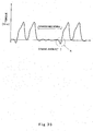
- an expansion pause interval with a large angle interval is provided in an interval of a crank angle (rotational phase angle of a crankshaft) of expansion strokes (region where the torque increases in Fig. 35 ) occurring successively. So, the expansion pause interval in which a low torque continues for a long time exists in the engine configured to expand at unequal intervals.
- the torque is likely to be decreased in the expansion pause interval in which the interval between expansions is long, and the torque for executing the compression stroke insufficient in the expansion pause interval. This may sometimes generate a negative torque as shown in part A in Fig. 35 .
- a fluctuation including a negative value occurs in the torque from the engine, a rotational fluctuation of the engine becomes large.
- a vibration of a vehicle body becomes large, and driving feeling becomes worse.
- the rotational fluctuation can be reduced by increasing a fly wheel mass (rotational inertia mass) of the engine. This may degrade a driving power performance and driving feeling during transient driving.
- an object of the present invention is to improve driving feeling while maintaining traction performance.
- the torque of the motor is added to a non-uniform torque of the engine configured to expand at unequal intervals so that decrease of the torque is suppressed.
- an increase in a rotational fluctuation of the engine can be inhibited while maintaining high traction performance by the engine configured to expand at unequal intervals, making it possible to improve driving feeling.
- the motor controller may be configured to control the motor so that a sum of the torque of the motor and the torque of the engine is maintained at a positive value.
- the torque of the motor is controlled so that the torque applied to the drive wheel is maintained at a positive value even when a fluctuation including a negative value is generated in the torque of the engine configured to expand at unequal intervals. Therefore, the increase in the rotational fluctuation of the engine is inhibited, and the torque is generated stably without changing its direction. As a result, driving feeling is improved.
- the motor controller may be configured to execute control to cause the motor to output a constant torque according to a throttle operation amount.
- the decrease of the torque in the compression stroke in which the torque of the engine is likely to be decreased can be suppressed by adding the torque of the motor to the torque of the engine.
- the torque of the motor may be constant when the throttle operation amount is constant, motor control is advantageously facilitated.
- the engine may be configured such that compression strokes of at least two cylinders occur simultaneously; and the motor controller may be configured to execute control so that the torque of the motor in the compression strokes occurring simultaneously is larger than the torque of the motor in the other strokes.
- the torque of the motor is increased at spots in the compression strokes occurring simultaneously in which the torque of the engine is likely to be decreased, an electric power consumed for the motor is suppressed and energy saving is achieved while effectively inhibiting a significant reduction of the torque applied to the drive wheel.
- the motor controller may be configured to execute control to drive the motor when an engine speed of the engine is a predetermined value or lower.
- the motor controller may stop driving of the motor when a driver is performing a throttle operation to decrease a speed of the vehicle.
- the motor may generate a positive torque in order to reduce an engine braking force, or otherwise may generate a negative torque in order to increase the engine braking force.
- the engine may further comprise a slip detecting device configured to detect a slip of a drive wheel with respect to a ground surface; and the motor controller may be configured to decrease the torque of the motor to be lower than a value before detection of the slip when the slip detecting device detects occurrence of the slip.
- the vehicle may further comprise a tilting sensor capable of detecting that the vehicle body is tilted rightward or leftward with respect to a driving direction of the vehicle; and the motor controller may be configured to decrease the torque of the motor when the tilting sensor detects that the vehicle body is tilted a predetermined angle or larger.
- the present invention provides a motor controller for a vehicle having the features of claim 8.
- the assist control is executed so that the torque of the motor is added to the torque of the engine configured to expand at unequal intervals in which the torque is likely to be non-uniform so that decrease of the torque is suppressed.
- the increase in the rotational fluctuation of the engine can be inhibited while maintaining high traction performance by the engine configured to expand at unequal intervals, making it possible to improve driving feeling.
- Fig. 1 is a side view of a motorcycle 1 according to a first embodiment of the present invention, showing a cowling 22 partly cutaway.
- the motorcycle 1 includes a front wheel 2 and a rear wheel 3.
- the front wheel 2 is rotatably mounted to a lower portion of a front fork 5 extending substantially vertically.
- the front fork 5 is mounted on a steering shaft (not shown) by an upper bracket (not shown) attached to an upper end portion thereof, and an under bracket located below the upper bracket.
- the steering shaft is rotatably supported by a head pipe 6.
- a bar-type steering handle 4 extending rightward and leftward is attached to the upper bracket. When the driver rotates the steering handle 4 clockwise or counterclockwise, the front wheel 2 is turned to a desired direction around the steering shaft which is a rotational shaft.
- a pair of right and left main frame members 7 extends rearward from the head pipe 6 to be tilted slightly in a downward direction.
- a pair of right and left pivot frame members 8 is coupled to rear portions of the main frame members 7.
- a swing arm 9 extending substantially forward and rearward is pivotally mounted at a front end portion thereof to each pivot frame member 8.
- the rear wheel 3, which is a drive wheel, is rotatably mounted to a rear portion of the swing arm 9.
- a fuel tank 10 is disposed behind the steering handle 4, and a driver straddle-seat 11 is mounted behind the fuel tank 10.
- An in-line four-cylinder engine E in which cylinders are arranged in a lateral direction (rightward and leftward direction) with respect to a driving direction of the vehicle is mounted between the front wheel 2 and the rear wheel 3 such that the engine E is supported on the main frame members 7 and the pivot frame members 8.
- the engine E includes the crankcase 12 accommodating a crankshaft 13, a cylinder block 14 which is coupled to an upper portion of the crankcase 12 and forms in-line four cylinders, a cylinder head 15 which is coupled to an upper portion of the cylinder block 14, forms a combustion chamber together with the cylinder block 14, and is provided with a DOHC type valve system, and a cylinder head cover 16 covering an upper portion of the cylinder head 15.
- the engine E is substantially L-shaped in a side view by the crankcase 12 elongated horizontally and the cylinder block 14 protruding upward from a front portion of the crankcase 12.
- a motor M described later is disposed in a space formed behind the cylinder block 14 and above the crankcase 12.
- An intake port 17 opens in a rear portion of the cylinder head 15 of the engine E.
- a throttle device 18 is coupled to the intake port 17 and is disposed inward of the main frame members 7.
- An air cleaner box 19 is disposed below the fuel tank 10 and is coupled to an upstream side of the throttle device 18. The air cleaner box 19 is configured to take in ambient air utilizing a running pressure (ram pressure) from forward.
- An exhaust port 20 is formed at a front portion of the cylinder head 15 to open forward and downward.
- An upstream end of the exhaust pipe 21 is coupled to the exhaust port 20.
- the exhaust pipe 21 is guided downward from the exhaust port 20 in front of the engine E, and extends rearward through a region below the engine E.
- a cowling 22 is provided from a front part of a vehicle body to side portions of the vehicle body so as to cover the engine E and other components. In Fig. 1 , the cowling 22 is partly cutaway so that the engine E is visually observed.
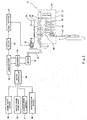
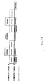
- Fig. 2 is a block diagram of the motorcycle 1.
- the crankcase 12 accommodates the crankshaft 13 coupled to a connecting rod 24 of a piston 23 of the engine E, and a first clutch gear 26 is mounted on one end portion of the crankshaft 13.
- a second clutch gear 27 is externally rotatably fitted to a main shaft 29 and is in mesh with the first clutch gear 26.
- a countershaft 30 is coupled to the main shaft 29 via a gear train 44 and is able to change its speed.
- the countershaft 30 is coupled to the rear wheel 3 via, for example, a chain 31.
- a path extending from the crankshaft 13 to the rear wheel 3 via the main shaft 29, the countershaft 30, and others form a driving power transmission system.
- a torque of the motor M is transmitted to an opposite end portion of the crankshaft 13 via a belt 32.
- the motor M is supplied with an electric power from a large battery 33 (see battery of, for example, 144V) of a large volume and a large voltage via an inverter 34.
- a motor controller 38 is coupled to the inverter 34 and controls driving timings and torques of the motor M.
- a crank angle sensor 39 that detects a rotational angle of the crankshaft 13, a throttle opening degree sensor 40 that detects an opening degree of a throttle valve (not shown) within the throttle device 18, a vehicle speed sensor 41 that detects a vehicle speed of the motorcycle 1, and a gear position sensor 42 that detects a mesh position of the gear train 44 of the crankcase 12, are respectively coupled to the motor controller 38.
- the crankcase 12 includes a transmission case containing the gear train 44.
- the torque of a starter motor 35 is transmitted to the crankshaft 13.
- the starter motor 35 outputs a power smaller than that of the motor M.
- the starter motor 35 is driven according to an ON-operation of a starter switch (not shown) performed by the driver at start-up of the engine.
- the starter motor 35 is supplied with the electric power from a small battery 37 of, for example, 14V, for supplying the electric power to electric components.
- the small battery 37 is coupled to a large battery 33 via a DC/DC converter 36.
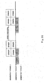
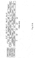
- Fig. 3A is a view showing timings of expansion strokes of the in-line four-cylinder engine mounted in the motorcycle of Fig. 1 .
- Fig. 3B is a view showing a relationship between generated torques and strokes in Fig. 3A .
- expansion strokes of the first cylinder and the fourth cylinder of the engine E occur at equal crank angles
- expansion strokes of the second cylinder and the third cylinder of the engine E occur at equal crank angles.
- the interval of the crank angle from the expansion strokes of the first cylinder and the fourth cylinder to the expansion strokes of the second cylinder and the third cylinder is 180 degrees, while the interval of the crank angle from the expansion strokes of the second cylinder and the third cylinder to the expansion strokes of the first cylinder and the fourth cylinder is 540 degrees.
- An expansion pause interval (360 degrees to 720 degrees) in which there are no expansion strokes is provided at an interval of crank angle of 360 degrees. In other words, the intervals at which the expansion strokes of the engine occur are set to unequal intervals.
- the motor controller 38 determines whether or not an engine speed is not higher than a predetermined value (e.g., 6000rpm) based on information from the crank angle sensor 39. If it is determined that the engine speed is not higher than the predetermined value, the motor controller 38 further determines whether or not a throttle operation being performed by the driver is to decrease the vehicle speed of the vehicle, based on information from the crank angle sensor 39, the throttle opening degree sensor 40, the vehicle speed sensor 41, the gear position sensor 42, and others. If it is determined that the throttle operation is not to decrease the vehicle speed of the vehicle, the motor controller 38 starts assist control described below in detail.
- a predetermined value e.g., 6000rpm
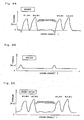
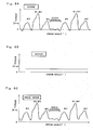
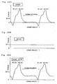
- Fig. 4A is a graph showing a relationship between the torque of the engine mounted in the motorcycle of Fig. 1 , and the crank angle.
- Fig. 4B is a graph showing a relationship between the torque of the motor mounted in the motorcycle of Fig. 1 and the crank angle.
- Fig. 4C is a graph showing a relationship between the torque of the engine of Fig. 4A and the motor of Fig. 4B , and the crank angle.
- Figs. 4A to 4C show that an amount of the throttle operation performed by the driver is constant. As shown in Fig.
- the torque of the engine E increases in value so as to correspond to the expansion strokes of the respective cylinders, and decreases in an expansion pause interval from the expansion strokes of the second cylinder and the third cylinder to the expansion strokes of the first cylinder and the fourth cylinder (in Fig. 4A , # 1 indicates the first cylinder, #2 indicates the second cylinder, #3 indicates the third cylinder, and #4 indicates the fourth cylinder).
- # 1 indicates the first cylinder
- #2 indicates the second cylinder
- #3 indicates the third cylinder
- #4 indicates the fourth cylinder.
- the torque has a negative value because a rotational inertia force of the crankshaft 13 is small.
- the motor controller 38 is configured to execute control so that the motor M outputs a predetermined torque according to a throttle operation amount (throttle opening degree) (assist control).
- a throttle operation amount throttle opening degree
- Figs. 4A to 4C show that the amount of throttle operation performed by the driver is constant, and therefore the torque of the motor M becomes constant.
- the torque of the motor M is controlled to have a value according to the change in the amount of throttle operation.
- the value of the predetermined torque may be varied according to the amount of throttle operation or may be set equal regardless of change in the amount of throttle operation. In other words, the value of the predetermined torque may be constant or variable according to change in the amount of throttle operation.
- the motor controller 38 stops the above mentioned assist control if it is determined that the engine speed is not lower than a predetermined value or is decreasing.
- the assist control is executed so that the torque of the motor M is added to the torque of the engine E. Therefore, the torque can be maintained at a positive value even during the compression stroke in the expansion pause interval in which the torque from the engine E is likely to be decreased. As a result, an increase in a rotational fluctuation of the engine E is inhibited while maintaining high traction performance by the engine configured to expand at unequal intervals, making it possible to improve driving feeling.
- the motor control becomes easy because the torque of the motor M may be set constant when the amount of throttle operation is constant. Furthermore, when the engine speed exceeds the predetermined value and the torque fluctuation is reduced, the assist control is stopped so that electric power consumption of the motor M is suppressed. Thus, energy saving is achieved.
- Fig. 5A is a graph showing the relationship between the torque of the engine and the crank angle according to the first alternative example.
- Fig. 5B is a graph showing the relationship between the torque of the motor and the crank angle according to the first alternative example.
- Fig. 5C is a graph showing the relationship between the torque of the engine and the motor, and the crank angle according to the first alternative example.
- Fig. 5A is identical to Fig. 4A .
- the motor controller 38 drives the motor M at spots so as to correspond to the compression strokes of the first cylinder and the fourth cylinder in the expansion pause interval so that the torque of the motor M is added to the torque of the engine E (assist control).
- the torque transmitted to the rear wheel 3 ( Fig. 2 ) which is a drive wheel is maintained so that a sum of the torque of the engine E ( Fig. 2 ) and the torque of the motor M ( Fig. 2 ) does not have a negative value.
- the torque of the motor M ( Fig. 2 ) is generated at spots in the compression stroke in the expansion pause interval, and the motor M ( Fig. 2 ) is not driven in other strokes, the electric power consumed in the motor M ( Fig. 2 ) is suppressed.
- energy saving is achieved.
- Fig. 6A is a graph showing the relationship between the torque of the engine and the crank angle according to the second alternative example.
- Fig. 6B is a graph showing the relationship between the torque of the motor and the crank angle according to the second alternative example.
- Fig. 6C is a graph showing the relationship between the torque of the engine and the motor, and the crank angle according to the second alternative example.
- Fig. 6A is identical to Fig. 4A .
- the motor controller 38 increases the torque of the motor M ( Fig.
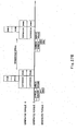
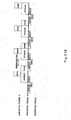
- Fig. 7A is a view showing timings of expansion strokes of an in-line four-cylinder engine mounted in a motorcycle according to a second embodiment.
- Fig. 7B is a view showing timings of expansion strokes of another in-line four-cylinder engine mounted in the motorcycle of the second embodiment.
- Fig. 7C is a view showing a relationship between generated torques and strokes in the second embodiment.
- Fig. 7A and Fig. 7B show substantially the same torque performance, which will be described collectively in this embodiment.
- the engine of this embodiment is mountable in the motorcycle of the first embodiment.
- the expansion strokes of the first cylinder and the fourth cylinder occur simultaneously, and then the expansion stroke of only the second cylinder (or third cylinder) occurs.
- the expansion stroke of the third cylinder, the expansion strokes of the first and fourth cylinders, and the expansion stroke of the second cylinder occur at interval of crank angle of 180 degrees.
- the interval of the crank angle from the expansion stroke of the second cylinder to the expansion stroke of the third cylinder is 360 degrees.
- An expansion pause interval in which there are no expansion strokes is provided at interval of crank angle of 180 degrees. In other words, the intervals at which the expansion strokes of the engine occur are set to unequal intervals.
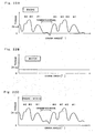
- Fig. 8A is a graph showing a relationship between the torque of the engine and the crank angle according to the second embodiment.
- Fig. 8B is a graph showing a relationship between the torque of the motor and the crank angle according to the second embodiment.
- Fig. 8C is a graph showing a relationship between the torque of the engine and the motor, and the crank angle according to the second embodiment.
- the torque of the engine E increases in value so as to correspond to the expansion strokes of the respective cylinders, and decreases in an expansion pause interval from the expansion stroke of the second expansion stroke to the expansion stroke of the third cylinder.
- the torque is lower and has a negative value in their compression strokes.
- the motor controller 38 ( Fig. 2 ) is configured to execute control so that the motor M ( Fig. 2 ) outputs a predetermined torque according to a throttle operation amount (assist control).
- a throttle operation amount (assist control)
- the torque transmitted to the rear wheel 3 ( Fig. 2 ) is maintained so that a sum of the torque of the engine E ( Fig. 2 ) and the torque of the motor M ( Fig. 2 ) does not have a negative value.
- the other configuration is similar to that of the first embodiment, and will not be further described.
- the output of the motor is constant, the above described first alternative example and the second alternative example may be applied.
- Fig. 9A is a view showing timings of expansion strokes of an in-line two-cylinder engine mounted in a motorcycle according to a third embodiment.
- Fig. 9B is a view showing timings of expansion strokes of another in-line two-cylinder engine mounted in the motorcycle of the third embodiment.
- Fig. 9C is a view showing a relationship between generated torques and strokes according to the third embodiment.
- Fig. 9A and Fig. 9B show substantially the same torque performance, which will be described collectively in this embodiment.
- the engine of this embodiment is an in-line two-cylinder engine, and the interval of the crank angle from the expansion stroke of the first cylinder to the expansion stroke of the second cylinder is 180 degrees, while the interval of the crank angle from the expansion stroke of the second cylinder to the expansion stroke of the first cylinder is 540 degrees, and the expansion pause interval in which there are no expansion strokes is provided at interval of crank angle of 360 degrees.
- the intervals at which the expansion strokes of the engine occur are set to unequal intervals.
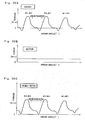
- Fig. 10A is a graph showing a relationship between the torque of the engine and the crank angle according to the third embodiment.
- Fig. 10B is a graph showing a relationship between the torque of the motor and the crank angle according to the third embodiment.
- Fig. 10C is a graph showing a relationship between the torque of the engine and the motor, and the crank angle according to the third embodiment.
- the torque of the engine increases in value so as to correspond to the expansion strokes of the respective cylinders, and decreases in the compression stroke in the expansion pause interval.
- the motor controller 38 ( Fig. 2 ) is configured to execute control so that the motor M ( Fig. 2 ) outputs a predetermined torque according to a throttle operation amount (assist control).
- a throttle operation amount (assist control)
- the torque transmitted to the rear wheel 3 ( Fig. 2 ) is maintained so that a sum of the torque of the engine E ( Fig. 2 ) and the torque of the motor M ( Fig. 2 ) does not have a negative value.
- the other configuration is similar to that of the first embodiment, and will not be further described.
- the output of the motor is constant, the above described first alternative example and the second alternative example may be applied.
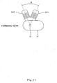
- Fig. 11 is a schematic side view showing a V-type two-cylinder engine.
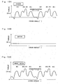
- Fig. 12A is a view showing timings of expansion strokes of the V-type two-cylinder engine mounted in the motorcycle according to the fourth embodiment.
- Fig. 12B is a view showing a relationship between generated torques and strokes according to the fourth embodiment.
- the engine of this embodiment is a V-type two-cylinder engine in which a pair of cylinders CY1 and CY2 form therebetween an open angle of ⁇ (50 degrees to 100 degrees).
- ⁇ 50 degrees to 100 degrees
- the interval of the crank angle from the expansion stroke of the first cylinder to the expansion stroke of the second cylinder is 360 degrees - ⁇
- the interval of the crank angle from the expansion stroke of the second cylinder to the expansion stroke of the first cylinder is 360 degrees + ⁇
- an expansion pause interval in which non-expansion-stroke interval is long is provided at interval of 180 degrees + ⁇ .
- the intervals at which the expansion strokes of the engine occur are set to unequal intervals.
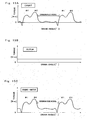
- Fig. 13A is a graph showing a relationship between the torque of the engine and the crank angle according to the fourth embodiment.
- Fig. 13B is a graph showing a relationship between the torque of the motor and the crank angle according to the fourth embodiment.
- Fig. 13C is a graph showing a relationship between the torque of the engine and the motor, and the crank angle according to the fourth embodiment.
- the torque of the engine increases in value so as to correspond to the expansion strokes of the respective cylinders, and decreases in compression strokes in the expansion pause interval.
- the motor controller 38 ( Fig. 2 ) is configured to execute control so that the motor M ( Fig. 2 ) outputs a predetermined torque according to a throttle operation amount (assist control).
- a throttle operation amount (assist control)
- the torque transmitted to the rear wheel 3 ( Fig. 2 ) is maintained so that a sum of the torque of the engine E ( Fig. 2 ) and the torque of the motor M ( Fig. 2 ) does not have a negative value.
- the other configuration is identical to that of the first embodiment and will not be further described.
- the output of the motor is constant, the above described first alternative example and the second alternative example may be applied.
- Fig. 14A is a view showing timings of expansion strokes of a V-type two-cylinder engine mounted in a motorcycle according to a fifth embodiment, which is different from that of the fourth embodiment.
- Fig. 14B is a view showing timings of expansion strokes of another V-type two-cylinder engine mounted in the motorcycle according to the fifth embodiment.
- Fig. 14C is a view showing a relationship between generated torques and strokes according to the fifth embodiment.
- Fig. 14A and Fig. 14B show substantially the same torque performance, which will be described collectively in this embodiment.
- the engine of this embodiment is a V-type two-cylinder engine in which a pair of cylinders form therebetween an open angle ⁇ (50 degrees to 100 degrees). Also, the interval of the crank angle from the expansion stroke of the first cylinder to the expansion stroke of the second cylinder is ⁇ , the interval of the crank angle from the expansion stroke of the second cylinder to the expansion stroke of the first cylinder is 540 degrees + ⁇ , an expansion pause interval in which there are no expansion strokes is provided at interval of crank angle of 540 degrees - ⁇ . In other words, the intervals at which the expansion strokes of the engine occur are set to unequal intervals.
- Fig. 15A is a graph showing a relationship between the torque of the engine and the crank angle according to the fifth embodiment.
- Fig. 15B is a graph showing a relationship between the torque of the motor and the crank angle according to the fifth embodiment.
- Fig. 15C is a graph showing a relationship between the torque of the engine and the motor, and the crank angle according to the fifth embodiment.
- the torque of the engine increases in value so as to correspond to the expansion strokes of the respective cylinders, and decreases in compression strokes in the expansion pause interval.
- the motor controller 38 ( Fig. 2 ) is configured to execute control so that the motor M ( Fig. 2 ) outputs a predetermined torque according to the throttle operation amount (assist control).
- the torque transmitted to the rear wheel 3 ( Fig. 2 ) is maintained so that a sum of the torque of the engine E ( Fig. 2 ) and the torque of the motor M ( Fig. 2 ) does not have a negative value.
- the motor output is constant, the above described first alternative example and the second alternative example may be applied.
- Fig. 16A is a schematic side view showing a V-type four-cylinder engine.
- Fig. 16B is a schematic plan view showing the V-type four-cylinder engine.
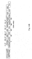
- Fig. 17A is a view showing timings of expansion strokes of the V-type four-cylinder engine mounted in the motorcycle of a sixth embodiment.
- Fig. 17B is a view showing a relationship between generated torques and strokes according to the sixth embodiment. As shown in Figs.
- the engine of this embodiment is a V-type four-cylinder engine in which the first cylinder CY1 and the third cylinder CY3 form an open angle of ⁇ (50 degrees to 100 degrees), and the second cylinder CY2 and the fourth cylinder CY4 form an open angle of ⁇ (50 degrees to 100 degrees). As shown in Fig.
- the interval of the crank angle from the expansion stroke of the first cylinder to the expansion stroke of the third cylinder is 180 degrees
- the interval of the crank angle from the expansion stroke of the third cylinder to the expansion stroke of the second cylinder is 360 degrees - ⁇
- the interval of the crank angle from the expansion stroke of the second cylinder to the expansion stroke of the fourth cylinder is 180 degrees
- the interval of the crank angle from the expansion stroke of the fourth cylinder to the expansion stroke of the first cylinder is ⁇
- the expansion pause interval in which there are no expansion strokes is provided at interval of crank angle ⁇ .
- the intervals at which the expansion strokes of the engine occur are set to unequal intervals.
- Fig. 18A is a graph showing a relationship between the torque of the engine and the crank angle according to the sixth embodiment.
- Fig. 18B is a graph showing a relationship between the torque of the motor and the crank angle according to the sixth embodiment.
- Fig. 18C is a graph showing a relationship between the torque of the engine and the motor and the crank angle according to the sixth embodiment.
- the torque of the engine increases in value so as to correspond to the expansion strokes of the respective cylinders, and decreases in compression strokes in expansion pause interval.
- the motor controller 38 ( Fig. 2 ) is configured to execute control so that the motor M ( Fig. 2 ) outputs a predetermined torque according to the throttle operation amount (assist control).
- the torque transmitted to the rear wheel 3 ( Fig. 2 ) is maintained so that a sum of the torque of the engine E ( Fig. 2 ) and the torque of the motor M ( Fig. 2 ) does not have a negative value.
- the motor output is constant, the above described first alternative example and second alternative example may be applied.
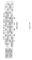
- Fig. 19A is a view showing timings of expansion strokes of a V-type four-cylinder engine which is mounted in a motorcycle of a seventh embodiment and has expansion strokes different from those of Fig. 17A .
- Fig. 19B is a view showing a relationship between generated torques and strokes according to the seventh embodiment.
- the engine of this embodiment is a V-type four-cylinder engine in which the first cylinder and the third cylinder form an open angle of ⁇ (50 degrees to 100 degrees) and the second cylinder and the fourth cylinder form an open angle of ⁇ (50 degrees to 100 degrees).
- the interval of the crank angle from the expansion stroke of the first cylinder to the expansion stroke of the second cylinder is 180 degrees - ⁇
- the interval of the crank angle from the expansion stroke of the second cylinder to the expansion stroke of the third cylinder is ⁇
- the interval of the crank angle from the expansion stroke of the third cylinder to the expansion stroke of the fourth cylinder is 180 degrees - ⁇
- the interval of the crank angle from the expansion stroke of the fourth cylinder to the expansion stroke of the first cylinder is 360 degrees + ⁇
- the expansion pause interval in which there are no expansion strokes is provided at interval of crank angle of 360 degrees + ⁇ .
- the intervals at which the expansion strokes of the engine occur are set to unequal intervals.
- Fig. 20A is a graph showing a relationship between the torque of the engine and the crank angle according to the seventh embodiment.
- Fig. 20B is a graph showing a relationship between the torque of the motor and the crank angle according to the seventh embodiment.
- Fig. 20C is a graph showing a relationship between the torque of the engine and the motor, and the crank angle according to the seventh embodiment.
- the torque of the engine increases in value so as to correspond to the expansion strokes of the respective cylinders, and decreases in compression strokes in expansion pause interval.
- the motor controller 38 ( Fig. 2 ) is configured to execute control so that the motor M ( Fig. 2 ) outputs a predetermined torque according to the throttle operation amount (assist control).
- the torque transmitted to the rear wheel 3 ( Fig. 2 ) is maintained so that a sum of the torque of the engine E ( Fig. 2 ) and the torque of the motor M ( Fig. 2 ) does not have a negative value.
- the motor output is constant, the above described first alternative example and second alternative example may be applied.
- Fig. 21A is a view showing timings of expansion strokes of a V-type four-cylinder engine which is mounted in a motorcycle of an eighth embodiment and has expansion strokes different from those of Fig. 17A and Fig. 19A .
- Fig. 21B is a view showing a relationship between generated torques and strokes according to the eighth embodiment.
- the engine of this embodiment is a V-type four-cylinder engine in which the first cylinder and the third cylinder form an open angle of ⁇ (50 degrees to 100 degrees) and the second cylinder and the fourth cylinder form an open angle of ⁇ (50 degrees to 100 degrees).
- the interval of the crank angle from the expansion stroke of the first cylinder to the expansion stroke of the fourth cylinder is 360 degrees - ⁇
- the interval of the crank angle from the expansion stroke of the fourth cylinder to the expansion stroke of the second cylinder is 180 degrees
- the interval of the crank angle from the expansion stroke of the second cylinder to the expansion stroke of the third cylinder is ⁇
- the interval of the crank angle from the expansion stroke of the third cylinder to the expansion stroke of the first cylinder is 180 degrees
- the expansion pause interval in which there are no expansion strokes is provided at interval of crank angle of 180 degrees - ⁇ .
- the intervals at which the expansion strokes of the engine occur are set to unequal intervals.
- Fig. 22A is a graph showing a relationship between the torque of the engine and the crank angle according to the eighth embodiment.
- Fig. 22B is a graph showing a relationship between the torque of the motor and the crank angle according to the eighth embodiment.
- Fig. 22C is a graph showing a relationship between the torque of the engine and the motor, and the crank angle according to the eighth embodiment.
- the torque of the engine increases in value so as to correspond to the expansion strokes of the respective cylinders, and decreases in compression strokes in the expansion pause interval.
- the motor controller 38 ( Fig. 2 ) is configured to execute control so that the motor M ( Fig. 2 ) outputs a predetermined torque according to the throttle operation amount (assist control).
- the torque transmitted to the rear wheel 3 ( Fig. 2 ) is maintained so that a sum of the torque of the engine E ( Fig. 2 ) and the torque of the motor M ( Fig. 2 ) does not have a negative value.
- the motor output is constant, the above described first alternative example and second alternative example may be applied.
- Fig. 23A is a view showing timings of expansion strokes of a V-type four-cylinder engine mounted in a motorcycle of a ninth embodiment, which are different from the expansion strokes of Fig. 17A , Fig. 19A and Fig. 21A .
- Fig. 23B is a view showing a relationship between generated torques and strokes according to the ninth embodiment.
- the engine of this embodiment is a V-type four-cylinder engine in which the first cylinder and the third cylinder form therebetween an open angle of ⁇ (50 degrees to 100 degrees), and the second cylinder and the fourth cylinder form therebetween an open angle of ⁇ (50 degrees to 100 degrees).
- the interval of the crank angle from the expansion stroke of the first cylinder to the expansion stroke of the second cylinder is ⁇
- the interval of the crank angle from the expansion stroke of the second cylinder to the expansion stroke of the third cylinder is 540 degrees + ⁇
- the interval of the crank angle from the expansion stroke of the third cylinder to the expansion stroke of the fourth cylinder is ⁇
- the interval of the crank angle from the expansion stroke of the fourth cylinder to the expansion stroke of the first cylinder is ⁇
- expansion pause interval in which there are no expansion strokes is provided at interval of crank angle of 360 degrees - ⁇ .
- the intervals at which the expansion strokes of the engine occur are set to unequal intervals.
- Fig. 24A is a graph showing a relationship between the torque of the engine and the crank angle according to the ninth embodiment.
- Fig. 24B is a graph showing a relationship between the torque of the motor and the crank angle according to the ninth embodiment.
- Fig. 24C is a graph showing a relationship between the torque of the engine and the motor, and the crank angle according to the ninth embodiment.
- the torque of the engine increases in value so as to correspond to the expansion strokes of the respective cylinders, and decreases in compression strokes in the expansion pause interval.
- the motor controller 38 ( Fig. 2 ) is configured to execute control so that the motor M ( Fig. 2 ) outputs a predetermined torque according to a throttle operation amount (assist control).
- a throttle operation amount (assist control)
- the torque transmitted to the rear wheel 3 ( Fig. 2 ) is maintained so that a sum of the torque of the engine E ( Fig. 2 ) and the torque of the motor M ( Fig. 2 ) does not have a negative value.
- the other configuration is identical to that of the first embodiment and will not be further described.
- the motor output is constant, the above described first alternative example and second alternative example may be applied.
- Fig. 25A is a view showing timings of expansion strokes of a V-type four-cylinder engine mounted in a motorcycle according to a tenth embodiment, which are different from the expansion strokes of Fig. 17A , Fig. 19A , Fig 21A and Fig. 23A .
- Fig. 25B is a view showing a relationship between generated torques and strokes according to the tenth embodiment.
- the engine of this embodiment is a V-type four-cylinder engine in which the first cylinder and the third cylinder form therebetween an open angle of ⁇ (50 degrees to 100 degrees) and the second cylinder and the fourth cylinder form an open angle of ⁇ (50 degrees to 100 degrees).
- the interval of the crank angle from the expansion stroke of the first cylinder to the expansion stroke of the fourth cylinder is ⁇
- the interval of the crank angle from the expansion stroke of the fourth cylinder to the expansion stroke of the third cylinder is 360 degrees - ⁇
- the interval of the crank angle from the expansion stroke of the third cylinder to the expansion stroke of the second cylinder is ⁇
- the interval of the crank angle from the expansion stroke of the second cylinder to the expansion stroke of the first cylinder is 360 degrees - ⁇
- the expansion pause interval in which there are no expansion strokes is provided at interval of crank angle of 180 degrees - ⁇ .
- the intervals at which the expansion strokes of the engine occur are set to unequal intervals.
- Fig. 26A is a graph showing a relationship between the torque of the engine and the crank angle according to the tenth embodiment.
- Fig. 26B is a graph showing a relationship between the torque of the motor and the crank angle according to the tenth embodiment.
- Fig. 26C is a graph showing a relationship between the torque of the engine and the motor, and the crank angle according to the tenth embodiment.
- the torque of the engine increases in value so as to correspond to the expansion strokes of the respective cylinders, and decreases in compression strokes in the expansion pause interval.
- the motor controller 38 ( Fig. 2 ) is configured to execute control so that the motor M ( Fig. 2 ) outputs a predetermined torque according to a throttle operation amount (assist control).
- a throttle operation amount (assist control)
- the torque transmitted to the rear wheel 3 ( Fig. 2 ) is maintained so that a sum of the torque of the engine E ( Fig. 2 ) and the torque of the motor M ( Fig. 2 ) does not have a negative value.
- the other configuration is identical to that of the first embodiment and will not be further described. Whereas in the tenth embodiment, the motor output is constant, the above described first alternative example and second alternative example may be applied.
- Fig. 27A is a view showing timings of expansion strokes of a V-type four-cylinder engine mounted in a motorcycle according to an eleventh embodiment, which are different from the expansion strokes of Fig. 17A , Fig. 19A , Fig. 21A , Fig. 23A , and Fig. 25A .
- Fig. 27B is a view showing a relationship between generated torques and strokes according to the eleventh embodiment.
- the engine of this embodiment is a V-type four-cylinder engine in which the first cylinder and the third cylinder form therebetween an open angle of ⁇ (50 degrees to 100 degrees) and the second cylinder and the fourth cylinder form an open angle of ⁇ (50 degrees to 100 degrees).
- the expansion stroke of the first cylinder and the expansion stroke of the third cylinder occur at equal crank angles, and the expansion stroke of the second cylinder and the expansion stroke of the fourth cylinder occur at equal crank angles.
- the interval of the crank angle from the expansion strokes of the first cylinder and the third cylinder to the expansion strokes of the second cylinder and the fourth cylinder is ⁇ .
- the expansion pause interval in which there are no expansion strokes is provided at interval of crank angle of 540 degrees - ⁇ . In other words, the intervals at which the expansion strokes of the engine occur are set to unequal intervals.
- Fig. 28A is a graph showing a relationship between the torque of the engine and the crank angle according to the eleventh embodiment.
- Fig. 28B is a graph showing a relationship between the torque of the motor and the crank angle according to the eleventh embodiment.
- Fig. 28C is a graph showing a relationship between the torque of the engine and the motor, and the crank angle according to the eleventh embodiment.
- the torque of the engine increases in value so as to correspond to the expansion strokes of the respective cylinders, and decreases in compression strokes in the expansion pause interval.
- the motor controller 38 ( Fig. 2 ) is configured to execute control so that the motor M ( Fig. 2 ) outputs a predetermined torque according to a throttle operation amount (assist control).
- a throttle operation amount (assist control)
- the torque transmitted to the rear wheel 3 ( Fig. 2 ) is maintained so that a sum of the torque of the engine E ( Fig. 2 ) and the torque of the motor M ( Fig. 2 ) does not have a negative value.
- the other configuration is identical to that of the first embodiment and will not be further described.
- the motor output is constant, the above described first alternative example and second alternative example may be applied.
- Fig. 29A is a view showing timings of expansion strokes of a V-type four-cylinder engine mounted in a motorcycle according to a twelfth embodiment, which are different from the expansion strokes of Fig. 17A , Fig. 19A , Fig. 21A , Fig. 23A , Fig. 25A , and Fig. 27A .
- Fig. 29B is a view showing a relationship between generated torques and strokes according to the twelfth embodiment. As shown in Figs.
- the engine of this embodiment is a V-type four-cylinder engine in which the first cylinder and the third cylinder form therebetween an open angle of ⁇ (50 degrees to 100 degrees), and the second cylinder and the fourth cylinder form an open angle of ⁇ (50 degrees to 100 degrees).
- the expansion stroke of the first cylinder and the expansion stroke of the third cylinder occur at equal crank angles, and the expansion stroke of the second cylinder and the expansion stroke of the fourth cylinder occur at equal crank angles.
- the interval of the crank angle from the expansion strokes of the first cylinder and the third cylinder to the expansion strokes of the second cylinder and the fourth cylinder is 360 degrees + ⁇
- the interval of the crank angle from the expansion strokes of the second cylinder and the fourth cylinder to the expansion strokes of the first cylinder and the third cylinders is 360 degrees - ⁇
- the expansion pause interval in which there are no expansion strokes is provided at interval of crank angle of 540 degrees - ⁇ .
- the intervals at which the expansion strokes of the engine occur are set to unequal intervals.
- Fig. 30A is a graph showing a relationship between the torque of the engine and the crank angle according to the twelfth embodiment.
- Fig. 30B is a graph showing a relationship between the torque of the motor and the crank angle according to the twelfth embodiment.
- Fig. 30C is a graph showing a relationship between the torque of the engine and the motor, and the crank angle according to the twelfth embodiment.
- the torque of the engine increases in value so as to correspond to the expansion strokes of the respective cylinders, and decreases in compression strokes in the expansion pause interval.
- the motor controller 38 ( Fig. 2 ) is configured to execute control so that the motor M ( Fig. 2 ) outputs a predetermined torque according to a throttle operation amount (assist control).
- a throttle operation amount (assist control)
- the torque transmitted to the rear wheel 3 ( Fig. 2 ) is maintained so that a sum of the torque of the engine E ( Fig. 2 ) and the torque of the motor M ( Fig. 2 ) does not have a negative value.
- the other configuration is identical to that of the first embodiment and will not be further described. Whereas in the twelfth embodiment, the motor output is constant, the above described first alternative example and second alternative example may be applied.
- Fig. 31A is a view showing timings of expansion strokes of a V-type four-cylinder engine mounted in a motorcycle according to a thirteenth embodiment, which are different from the expansion strokes of Fig. 17A , Fig. 19A , Fig. 21A , Fig. 23A , Fig. 25A , Fig. 27A , and Fig. 29A .
- Fig. 31B is a view showing a relationship between generated torques and strokes according to the thirteenth embodiment. As shown in Figs.
- the engine of this embodiment is a V-type four-cylinder engine in which the first cylinder and the third cylinder form therebetween an open angle of ⁇ (50 degrees to 100 degrees) and the second cylinder and the fourth cylinder form an open angle of ⁇ (50 degrees to 100 degrees).
- the interval of the crank angle from the expansion stroke of the first cylinder to the expansion stroke of the second cylinder is ⁇
- the interval of the crank angle from the expansion stroke of the second cylinder to the expansion stroke of the third cylinder is 360 degrees - ⁇
- the interval of the crank angle from the expansion stroke of the third cylinder to the expansion stroke of the fourth cylinder is ⁇
- the interval of the crank angle from the expansion stroke of the fourth cylinder to the expansion stroke of the first cylinder is 360 degrees - ⁇
- the expansion pause interval in which there are no expansion strokes is provided at interval of crank angle of 180 degrees - ⁇ .
- the intervals at which the expansion strokes of the engine occur are set to unequal intervals.
- Fig. 32A is a graph showing a relationship between the torque of the engine and the crank angle according to the thirteenth embodiment.
- Fig. 32B is a graph showing a relationship between the torque of the motor and the crank angle according to the thirteenth embodiment.
- Fig. 32C is a graph showing a relationship between the torque of the engine and the motor, and the crank angle according to the thirteenth embodiment.
- the torque of the engine increases in value so as to correspond to the expansion strokes of the respective cylinders, and decreases in compression strokes in the expansion pause interval.
- the motor controller 38 ( Fig. 2 ) is configured to execute control so that the motor M ( Fig. 2 ) outputs a predetermined torque according to a throttle operation amount (assist control).
- a throttle operation amount (assist control)
- the torque transmitted to the rear wheel 3 ( Fig. 2 ) is maintained so that a sum of the torque of the engine E ( Fig. 2 ) and the torque of the motor M ( Fig. 2 ) does not have a negative value.
- the other configuration is identical to that of the first embodiment and will not be further described.
- the motor output is constant, the above described first alternative example and second alternative example may be applied.
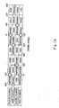
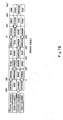
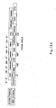
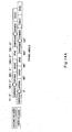
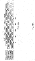
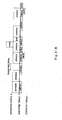
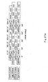
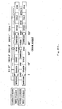
- Fig. 33 is a table showing a comparison of the degree with which the negative torque is likely to be generated in the first to thirteenth embodiments.
- the degree with which the negative torque is likely to be generated in various engines configured to expand at unequal intervals are varied depending on their components and configurations.
- the negative torque is likely to be generated in an engine driving power output.
- the assist control of the present invention is particularly suitable for the cases where the compression stroke occurs simultaneously in a plurality of cylinders, or the expansion pause interval is long.
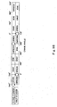
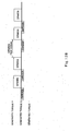
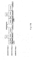
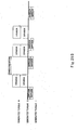
- Fig. 34 is a block diagram of a motorcycle according to the fourteenth embodiment.
- a front wheel rotational speed sensor 44 that detects a rotational speed of the front wheel 2
- a rear wheel rotational speed sensor 45 that detects a rotational speed of the rear wheel 3 are coupled to the motor controller 38, forming a slip detecting device 43.
- the motor controller 38 is configured to determine that the rear wheel 3 which is a drive wheel has slipped on a ground surface, when a difference between the rotational speed detected by the front wheel rotational speed sensor 44 and the rotational speed detected by the rear wheel rotational speed sensor 45 is a predetermined value or larger.
- a tilting sensor 46 is coupled to the motor controller 38 to detect that the vehicle body of the motorcycle 1 is tilted a predetermined angle or larger with respect to the driving direction.
- the motor controller 38 determines whether or not the rear wheel 3 has slipped on the ground surface based information from the slip detecting device 43. If it is determined that the rear wheel 3 has slipped, the motor controller 38 decreases the torque of the motor M to restore the gripping force of the rear wheel 3 with respect to the ground surface. Furthermore, the motor controller 38 determines whether or not the vehicle body of the motorcycle 1 is tilted the predetermined angle or larger with respect to the driving direction based on the information from the tilting sensor 46. If it is determined that the vehicle body is tilted the predetermined angle or larger, the motor controller 38 decreases the torque of the motor M to maintain the gripping force of the rear wheel 3 with respect to the ground surface. Moreover, this embodiment is applicable to all the above described embodiments.
Landscapes
- Engineering & Computer Science (AREA)
- Mechanical Engineering (AREA)
- Transportation (AREA)
- Combustion & Propulsion (AREA)
- Chemical & Material Sciences (AREA)
- Power Engineering (AREA)
- General Engineering & Computer Science (AREA)
- Life Sciences & Earth Sciences (AREA)
- Sustainable Development (AREA)
- Sustainable Energy (AREA)
- Automation & Control Theory (AREA)
- Control Of Vehicle Engines Or Engines For Specific Uses (AREA)
- Hybrid Electric Vehicles (AREA)
- Combined Controls Of Internal Combustion Engines (AREA)
- Electric Propulsion And Braking For Vehicles (AREA)
Description
- The present invention relates to a vehicle such as a motorcycle which is equipped with an engine configured to expand at unequal intervals and, more particularly to a motor controller configured to control a motor built into the vehicle, according to the preamble of
claim 1 and as it is disclosed inUS 2002104499 A . - In a multiple-cylinder engine equipped in a conventional motorcycle, typically, angles of crank angles at which expansion strokes of respective cylinders occur are set to equal intervals. A torque transmitted from the engine to a drive wheel is high in the expansion stroke in the engine and is low in other strokes (intake, compression, and exhaust). In an engine configured to expand at equal intervals, the torque in the expansion stroke is generated at equal intervals and fluctuates regularly. In the engine configured to expand at equal intervals, when the torque of the drive wheel exceeds a slip limit value with respect to a ground surface for a moment in an expansion stroke, a high torque in a next expansion stroke is generated before a gripping force with respect to the ground surface is restored, because an interval before occurrence of the next expansion stroke is short. In this situation, a slip may occur.
- Accordingly, an engine has been proposed, in which expansion strokes of respective cylinders of the multiple-cylinder engine are generated at unequal intervals by, for example, arranging crank pins corresponding to the cylinders at unequal angles (see Japanese Patent Application Publication No.
3656921 Fig. 35 , in the engine configured to expand at unequal intervals, an expansion pause interval with a large angle interval is provided in an interval of a crank angle (rotational phase angle of a crankshaft) of expansion strokes (region where the torque increases inFig. 35 ) occurring successively. So, the expansion pause interval in which a low torque continues for a long time exists in the engine configured to expand at unequal intervals. Therefore, even if the drive wheel exceeds a slip limit with respect to a ground surface for a moment in the expansion stroke in which the generated torque is high, the gripping force of the drive wheel with respect to the ground surface is restored in the expansion pause interval. That is, by making timings when the high torque is generated irregular, traction performance of the drive wheel is improved. - However, in the engine configured to expand at unequal intervals, the torque is likely to be decreased in the expansion pause interval in which the interval between expansions is long, and the torque for executing the compression stroke insufficient in the expansion pause interval. This may sometimes generate a negative torque as shown in part A in
Fig. 35 . Thus, if a fluctuation including a negative value occurs in the torque from the engine, a rotational fluctuation of the engine becomes large. As a result, a vibration of a vehicle body becomes large, and driving feeling becomes worse. Typically, the rotational fluctuation can be reduced by increasing a fly wheel mass (rotational inertia mass) of the engine. This may degrade a driving power performance and driving feeling during transient driving. - Accordingly, an object of the present invention is to improve driving feeling while maintaining traction performance.
- The present invention has been made under the circumstances, and a vehicle of the present invention comprises the features of
claim 1. - In such a configuration, the torque of the motor is added to a non-uniform torque of the engine configured to expand at unequal intervals so that decrease of the torque is suppressed. As a result, an increase in a rotational fluctuation of the engine can be inhibited while maintaining high traction performance by the engine configured to expand at unequal intervals, making it possible to improve driving feeling.
- The motor controller may be configured to control the motor so that a sum of the torque of the motor and the torque of the engine is maintained at a positive value.
- In such a configuration, the torque of the motor is controlled so that the torque applied to the drive wheel is maintained at a positive value even when a fluctuation including a negative value is generated in the torque of the engine configured to expand at unequal intervals. Therefore, the increase in the rotational fluctuation of the engine is inhibited, and the torque is generated stably without changing its direction. As a result, driving feeling is improved.
- In such a configuration, since the torque of the motor is added in the compression stroke of the engine configured to expand at unequal intervals in which the torque is likely to be non-uniform, a decrease of the torque in the compression stroke can be suppressed.
- The motor controller may be configured to execute control to cause the motor to output a constant torque according to a throttle operation amount.
- In such a configuration, the decrease of the torque in the compression stroke in which the torque of the engine is likely to be decreased can be suppressed by adding the torque of the motor to the torque of the engine. In addition, since the torque of the motor may be constant when the throttle operation amount is constant, motor control is advantageously facilitated.
- In such a configuration, since the torque of the engine is increased at spots in the compression stroke in the expansion pause interval in which the torque of the engine is likely to be decreased, an electric power consumed for the motor is suppressed and energy saving is achieved while effectively inhibiting a significant decrease of the torque applied to the drive wheel.
- The engine may be configured such that compression strokes of at least two cylinders occur simultaneously; and the motor controller may be configured to execute control so that the torque of the motor in the compression strokes occurring simultaneously is larger than the torque of the motor in the other strokes.
- In such a configuration, the torque of the motor is increased at spots in the compression strokes occurring simultaneously in which the torque of the engine is likely to be decreased, an electric power consumed for the motor is suppressed and energy saving is achieved while effectively inhibiting a significant reduction of the torque applied to the drive wheel.
- The motor controller may be configured to execute control to drive the motor when an engine speed of the engine is a predetermined value or lower.
- In such a configuration, since the motor is driven during low-speed rotation when an inertia force is small and a fluctuation of the torque is likely to be large, driving feeling can be improved effectively. Also, when the engine speed exceeds the predetermined value, the assist control is stopped so that consumption of the electric power is suppressed. As a result, energy saving can be achieved
- The motor controller may stop driving of the motor when a driver is performing a throttle operation to decrease a speed of the vehicle.
- In such a configuration, since the electric power consumed to drive the motor is saved, a large battery need not be built into the vehicle, making the vehicle body lightweight. It should be noted that while decreasing the vehicle speed, the motor may generate a positive torque in order to reduce an engine braking force, or otherwise may generate a negative torque in order to increase the engine braking force.
- The engine may further comprise a slip detecting device configured to detect a slip of a drive wheel with respect to a ground surface; and the motor controller may be configured to decrease the torque of the motor to be lower than a value before detection of the slip when the slip detecting device detects occurrence of the slip.
- In such a configuration, since the torque of the motor is decreased when the torque of the drive wheel exceeds the slip limit value and thereby the drive wheel is starting to slip on the ground surface, the torque of the drive wheel is suppressed to be smaller than the slip limit value immediately, and the gripping force of the drive wheel with respect to the ground surface can be restored.
- The vehicle may further comprise a tilting sensor capable of detecting that the vehicle body is tilted rightward or leftward with respect to a driving direction of the vehicle; and the motor controller may be configured to decrease the torque of the motor when the tilting sensor detects that the vehicle body is tilted a predetermined angle or larger.
- In such a configuration, since the torque of the motor is decreased when the vehicle body is tilted and thereby the gripping force of the drive wheel with respect to the ground surface is likely to be decreased, occurrence of the slip of the drive wheel with respect to the ground surface can be inhibited.
- Moreover, the present invention provides a motor controller for a vehicle having the features of
claim 8. - In such a configuration, the assist control is executed so that the torque of the motor is added to the torque of the engine configured to expand at unequal intervals in which the torque is likely to be non-uniform so that decrease of the torque is suppressed. As a result, the increase in the rotational fluctuation of the engine can be inhibited while maintaining high traction performance by the engine configured to expand at unequal intervals, making it possible to improve driving feeling.
-
-
Fig. 1 is a side view showing a motorcycle according to a first embodiment of the present invention; -
Fig. 2 is a block diagram of a driving power transmission system of the motorcycle ofFig. 1 ; -
Fig. 3A is a view showing timings of expansion strokes of an in-line four-cylinder engine mounted in the motorcycle ofFig. 1 ; -
Fig. 3B is a view showing a relationship between generated torques and strokes inFig. 3A ; -
Fig. 4A is a graph showing a relationship between a torque of the engine mounted in the motorcycle ofFig. 1 and a crank angle; -
Fig. 4B is a graph showing a relationship between a torque of a motor built into the motorcycle ofFig. 1 and the crank angle; -
Fig. 4C is a graph showing a relationship between a torque of the engine ofFig. 4A and the motor ofFig. 4B and the crank angle; -
Fig. 5A is a graph showing a relationship between a torque of an engine and a crank angle according to a first alternative example; -
Fig. 5B is a graph showing a torque of a motor and a crank angle according to the first alternative example; -
Fig. 5C is a graph showing a relationship between a torque of the engine and the motor, and the crank angle according to the first alternative example; -
Fig. 6A is a graph showing a relationship between a torque of the engine and the crank angle according to a second alternative example; -
Fig. 6B is a graph showing a torque of the motor and the crank angle according to the second alternative example; -
Fig. 6C is a graph showing a relationship between a torque of the engine and the motor, and the crank angle according to the second alternative example; -
Fig. 7A is a view showing timings of expansion strokes of an in-line four-cylinder engine mounted in a motorcycle according to a second embodiment; -
Fig. 7B is a view showing timings of expansion strokes of another in-line four-cylinder engine mounted in the motorcycle according to the second embodiment; -
Fig. 7C is a view showing a relationship between generated torques and strokes according to the second embodiment; -
Fig. 8A is a graph showing a relationship between the torque of the engine, and the crank angle according to the second embodiment; -
Fig. 8B is a graph showing a relationship between the torque of the motor and the crank angle according to the second embodiment; -
Fig. 8C is a graph showing a relationship between a torque of the engine and the motor, and the crank angle according to the second embodiment; -
Fig. 9A is a view showing timings of expansion strokes of an in-line two-cylinder engine mounted in a motorcycle according to a third embodiment; -
Fig. 9B is a view showing timings of expansion strokes of another in-line two-cylinder engine mounted in the motorcycle according to the third embodiment; -
Fig. 9C is a view showing a relationship between generated torques and strokes according to the third embodiment; -
Fig. 10A is a graph showing a relationship between the torque of the engine and the crank angle according to the third embodiment; -
Fig. 10B is a graph showing a relationship between the torque of the motor and the crank angle according to the third embodiment; -
Fig. 10C is a graph showing a relationship between the torque of the engine and the motor and the crank angle according to the third embodiment; -
Fig. 11 is a schematic side view showing a V-type two-cylinder engine; -
Fig. 12A is a view showing timings of expansion strokes of a V-type two-cylinder engine mounted in a motorcycle according to a fourth embodiment; -
Fig. 12B is a view showing a relationship between generated torques and strokes according to the fourth embodiment; -
Fig. 13A is a graph showing a relationship between the torque of the engine and the crank angle according to the fourth embodiment; -
Fig. 13B is a graph showing a relationship between the torque of the motor and the crank angle according to the fourth embodiment; -
Fig. 13C is a graph showing a relationship between the torque of the engine and the motor, and the crank angle according to the fourth embodiment; -
Fig. 14A is a view showing timings of expansion strokes of a V-type two-cylinder engine mounted in a motorcycle according to a fifth embodiment; -
Fig. 14B is a view showing timings of expansion strokes of another V-type two-cylinder engine mounted in the motorcycle according to the fifth embodiment; -
Fig. 14C is a view showing a relationship between generated torques and strokes according to the fifth embodiment; -
Fig. 15A is a graph showing a relationship between the torque of the engine and the crank angle according to the fifth embodiment; -
Fig. 15B is a graph showing a relationship between the torque of the motor and the crank angle according to the fifth embodiment; -
Fig. 15C is a graph showing a relationship between the torque of the engine and the motor, and the crank angle according to the fifth embodiment; -
Fig. 16A is a schematic side view showing a V-type four-cylinder engine; -
Fig. 16B is a schematic plan view showing the V-type four-cylinder engine; -
Fig. 17A is a view showing timings of expansion strokes of a V-type four-cylinder engine mounted in a motorcycle according to a sixth embodiment; -
Fig. 17B is a view showing a relationship between generated torques and strokes according to the sixth embodiment; -
Fig. 18A is a graph showing a relationship between the torque of the engine and the crank angle according to the sixth embodiment; -
Fig. 18B is a graph showing a relationship between the torque of the motor and the crank angle according to the sixth embodiment; -
Fig. 18C is a graph showing a relationship between the torque of the engine and the motor, and the crank angle according to the sixth embodiment; -
Fig. 19A is a view showing timings of expansion strokes of a V-type four-cylinder engine mounted in a motorcycle according to a seventh embodiment; -
Fig. 19B is a view showing a relationship between generated torques and strokes according to the seventh embodiment; -
Fig. 20A is a graph showing a relationship between the torque of the engine and the crank angle according to the seventh embodiment; -
Fig. 20B is a graph showing a relationship between the torque of the motor and the crank angle according to the seventh embodiment; -
Fig. 20C is a graph showing a relationship between the torque of the engine and the motor and the crank angle according to the seventh embodiment; -
Fig. 21A is a view showing timings of expansion strokes of a V-type four-cylinder engine mounted in a motorcycle according to an eighth embodiment; -
Fig. 21B is a view showing a relationship between generated torques and strokes according to the eighth embodiment; -
Fig. 22A is a graph showing a relationship between the torque of the engine and the crank angle according to the eighth embodiment; -
Fig. 22B is a graph showing a relationship between the torque of the motor and the crank angle according to the eighth embodiment; -
Fig. 22C is a graph showing a relationship between the torque of the engine and the motor, and the crank angle according to the eighth embodiment; -
Fig. 23A is a view showing timings of expansion strokes of a V-type four-cylinder engine mounted in a motorcycle according to a ninth embodiment; -
Fig. 23B is a view showing a relationship between generated torques and strokes according to the ninth embodiment; -
Fig. 24A is a graph showing a relationship between the torque of the engine and the crank angle according to the ninth embodiment; -
Fig. 24B is a graph showing a relationship between the torque of the motor and the crank angle according to the ninth embodiment; -
Fig. 24C is a graph showing a relationship between the torque of the engine and the motor, and the crank angle according to the ninth embodiment; -
Fig. 25A is a view showing timings of expansion strokes of a V-type four-cylinder engine mounted in a motorcycle according to a tenth embodiment; -
Fig. 25B is a view showing a relationship between generated torques and strokes according to the tenth embodiment; -
Fig. 26A is a graph showing a relationship between the torque of the engine and the crank angle according to the tenth embodiment; -
Fig. 26B is a graph showing a relationship between the torque of the motor and the crank angle according to the tenth embodiment; -
Fig. 26C is a graph showing a relationship between the torque of the engine and the motor, and the crank angle according to the tenth embodiment; -
Fig. 27A is a view showing timings of expansion strokes of a V-type four-cylinder engine mounted in a motorcycle according to an eleventh embodiment; -
Fig. 27B is a view showing a relationship between generated torques and strokes according to the eleventh embodiment; -
Fig. 28A is a graph showing a relationship between the torque of the engine and the crank angle according to the eleventh embodiment; -
Fig. 28B is a graph showing a relationship between the torque of the motor and the crank angle according to the eleventh embodiment; -
Fig. 28C is a graph showing a relationship between the torque of the engine and the motor, and the crank angle according to the eleventh embodiment; -
Fig. 29A is a view showing timings of expansion strokes of a V-type four-cylinder engine mounted in a motorcycle according to a twelfth embodiment; -
Fig. 29B is a view showing a relationship between generated torques and strokes according to the twelfth embodiment; -
Fig. 30A is a graph showing a relationship between the torque of the engine and the crank angle according to the twelfth embodiment; -
Fig. 30B is a graph showing a relationship between the torque of the motor and the crank angle according to the twelfth embodiment; -
Fig. 30C is a graph showing a relationship between the torque of the engine and the motor, and the crank angle according to the twelfth embodiment; -
Fig. 31A is a view showing timings of expansion strokes of a V-type four-cylinder engine mounted in a motorcycle according to a thirteenth embodiment; -
Fig. 31B is a view showing a relationship between generated torques and strokes according to the thirteenth embodiment; -
Fig. 32A is a graph showing a relationship between the torque of the engine and the crank angle according to the thirteenth embodiment; -
Fig. 32B is a graph showing a relationship between the torque of the motor and the crank angle according to the thirteenth embodiment; -
Fig. 32C is a graph showing a relationship between the torque of the engine and the motor, and the crank angle according to the thirteenth embodiment; -
Fig. 33 is a table showing comparison of degree with which a negative torque is likely to be generated, between the embodiments; -
Fig. 34 is a block diagram of the motorcycle according to a fourteenth embodiment; and -
Fig. 35 is a graph showing a relationship between a torque of an engine and a crank angle according to a prior art. - Hereinafter, a motorcycle according to embodiments of the present invention will be described with reference to the drawings. In the embodiments described below, the directions are referenced from the perspective of a driver (not shown) mounting the motorcycle.
-
Fig. 1 is a side view of amotorcycle 1 according to a first embodiment of the present invention, showing acowling 22 partly cutaway. As shown inFig. 1 , themotorcycle 1 includes afront wheel 2 and arear wheel 3. Thefront wheel 2 is rotatably mounted to a lower portion of afront fork 5 extending substantially vertically. Thefront fork 5 is mounted on a steering shaft (not shown) by an upper bracket (not shown) attached to an upper end portion thereof, and an under bracket located below the upper bracket. The steering shaft is rotatably supported by ahead pipe 6. A bar-type steering handle 4 extending rightward and leftward is attached to the upper bracket. When the driver rotates the steering handle 4 clockwise or counterclockwise, thefront wheel 2 is turned to a desired direction around the steering shaft which is a rotational shaft. - A pair of right and left
main frame members 7 extends rearward from thehead pipe 6 to be tilted slightly in a downward direction. A pair of right and leftpivot frame members 8 is coupled to rear portions of themain frame members 7. Aswing arm 9 extending substantially forward and rearward is pivotally mounted at a front end portion thereof to eachpivot frame member 8. Therear wheel 3, which is a drive wheel, is rotatably mounted to a rear portion of theswing arm 9. Afuel tank 10 is disposed behind thesteering handle 4, and a driver straddle-seat 11 is mounted behind thefuel tank 10. - An in-line four-cylinder engine E in which cylinders are arranged in a lateral direction (rightward and leftward direction) with respect to a driving direction of the vehicle is mounted between the
front wheel 2 and therear wheel 3 such that the engine E is supported on themain frame members 7 and thepivot frame members 8. The engine E includes thecrankcase 12 accommodating acrankshaft 13, acylinder block 14 which is coupled to an upper portion of thecrankcase 12 and forms in-line four cylinders, acylinder head 15 which is coupled to an upper portion of thecylinder block 14, forms a combustion chamber together with thecylinder block 14, and is provided with a DOHC type valve system, and acylinder head cover 16 covering an upper portion of thecylinder head 15. The engine E is substantially L-shaped in a side view by thecrankcase 12 elongated horizontally and thecylinder block 14 protruding upward from a front portion of thecrankcase 12. A motor M described later is disposed in a space formed behind thecylinder block 14 and above thecrankcase 12. - An
intake port 17 opens in a rear portion of thecylinder head 15 of the engine E. Athrottle device 18 is coupled to theintake port 17 and is disposed inward of themain frame members 7. An aircleaner box 19 is disposed below thefuel tank 10 and is coupled to an upstream side of thethrottle device 18. Theair cleaner box 19 is configured to take in ambient air utilizing a running pressure (ram pressure) from forward. Anexhaust port 20 is formed at a front portion of thecylinder head 15 to open forward and downward. An upstream end of theexhaust pipe 21 is coupled to theexhaust port 20. Theexhaust pipe 21 is guided downward from theexhaust port 20 in front of the engine E, and extends rearward through a region below the engineE. A cowling 22 is provided from a front part of a vehicle body to side portions of the vehicle body so as to cover the engine E and other components. InFig. 1 , thecowling 22 is partly cutaway so that the engine E is visually observed. -
Fig. 2 is a block diagram of themotorcycle 1. As shown inFig. 2 , thecrankcase 12 accommodates thecrankshaft 13 coupled to a connectingrod 24 of apiston 23 of the engine E, and a firstclutch gear 26 is mounted on one end portion of thecrankshaft 13. A secondclutch gear 27 is externally rotatably fitted to amain shaft 29 and is in mesh with the firstclutch gear 26. In a state where a main clutch 28 is fixed to an end portion of themain shaft 29 and is coupled to the secondclutch gear 27, themain shaft 29 rotates in association with thecrankshaft 13. Acountershaft 30 is coupled to themain shaft 29 via agear train 44 and is able to change its speed. Thecountershaft 30 is coupled to therear wheel 3 via, for example, achain 31. As described above, a path extending from thecrankshaft 13 to therear wheel 3 via themain shaft 29, thecountershaft 30, and others form a driving power transmission system. - A torque of the motor M is transmitted to an opposite end portion of the
crankshaft 13 via abelt 32. The motor M is supplied with an electric power from a large battery 33 (see battery of, for example, 144V) of a large volume and a large voltage via aninverter 34. Amotor controller 38 is coupled to theinverter 34 and controls driving timings and torques of the motor M. - A
crank angle sensor 39 that detects a rotational angle of thecrankshaft 13, a throttleopening degree sensor 40 that detects an opening degree of a throttle valve (not shown) within thethrottle device 18, avehicle speed sensor 41 that detects a vehicle speed of themotorcycle 1, and agear position sensor 42 that detects a mesh position of thegear train 44 of thecrankcase 12, are respectively coupled to themotor controller 38. In this embodiment, thecrankcase 12 includes a transmission case containing thegear train 44. - The torque of a
starter motor 35 is transmitted to thecrankshaft 13. Thestarter motor 35 outputs a power smaller than that of the motor M. Thestarter motor 35 is driven according to an ON-operation of a starter switch (not shown) performed by the driver at start-up of the engine. Thestarter motor 35 is supplied with the electric power from asmall battery 37 of, for example, 14V, for supplying the electric power to electric components. Thesmall battery 37 is coupled to alarge battery 33 via a DC/DC converter 36. When the electric power is generated by using the motor M as a power generator, it can be charged in thelarge battery 33, and the electric power accumulated in thelarge battery 33 is reduced in voltage by the DC/DC converter 36 and can be charged in thesmall battery 33. -
Fig. 3A is a view showing timings of expansion strokes of the in-line four-cylinder engine mounted in the motorcycle ofFig. 1 .Fig. 3B is a view showing a relationship between generated torques and strokes inFig. 3A . As shown inFig. 3A and3B , expansion strokes of the first cylinder and the fourth cylinder of the engine E occur at equal crank angles, and expansion strokes of the second cylinder and the third cylinder of the engine E occur at equal crank angles. The interval of the crank angle from the expansion strokes of the first cylinder and the fourth cylinder to the expansion strokes of the second cylinder and the third cylinder is 180 degrees, while the interval of the crank angle from the expansion strokes of the second cylinder and the third cylinder to the expansion strokes of the first cylinder and the fourth cylinder is 540 degrees. An expansion pause interval (360 degrees to 720 degrees) in which there are no expansion strokes is provided at an interval of crank angle of 360 degrees. In other words, the intervals at which the expansion strokes of the engine occur are set to unequal intervals. - Subsequently, a control procedure of the motor M built into the
motorcycle 1 will be described. After the engine E has started and themotorcycle 1 has started driving, themotor controller 38 determines whether or not an engine speed is not higher than a predetermined value (e.g., 6000rpm) based on information from thecrank angle sensor 39. If it is determined that the engine speed is not higher than the predetermined value, themotor controller 38 further determines whether or not a throttle operation being performed by the driver is to decrease the vehicle speed of the vehicle, based on information from thecrank angle sensor 39, the throttleopening degree sensor 40, thevehicle speed sensor 41, thegear position sensor 42, and others. If it is determined that the throttle operation is not to decrease the vehicle speed of the vehicle, themotor controller 38 starts assist control described below in detail. -
Fig. 4A is a graph showing a relationship between the torque of the engine mounted in the motorcycle ofFig. 1 , and the crank angle.Fig. 4B is a graph showing a relationship between the torque of the motor mounted in the motorcycle ofFig. 1 and the crank angle.Fig. 4C is a graph showing a relationship between the torque of the engine ofFig. 4A and the motor ofFig. 4B , and the crank angle.Figs. 4A to 4C show that an amount of the throttle operation performed by the driver is constant. As shown inFig. 4A , the torque of the engine E increases in value so as to correspond to the expansion strokes of the respective cylinders, and decreases in an expansion pause interval from the expansion strokes of the second cylinder and the third cylinder to the expansion strokes of the first cylinder and the fourth cylinder (inFig. 4A , # 1 indicates the first cylinder, #2 indicates the second cylinder, #3 indicates the third cylinder, and #4 indicates the fourth cylinder). Especially, in the compression strokes of the first cylinder and the fourth cylinder in the expansion pause interval, the torque has a negative value because a rotational inertia force of thecrankshaft 13 is small. - Accordingly, as shown in
Fig. 4B , themotor controller 38 is configured to execute control so that the motor M outputs a predetermined torque according to a throttle operation amount (throttle opening degree) (assist control). Thereby, as shown inFig. 4C , the torque transmitted to therear wheel 3 is maintained so that a sum of the torque of the engine E and the torque of the motor M does not have a negative value.Figs. 4A to 4C show that the amount of throttle operation performed by the driver is constant, and therefore the torque of the motor M becomes constant. When the amount of the throttle operation changes, the torque of the motor M is controlled to have a value according to the change in the amount of throttle operation. The value of the predetermined torque may be varied according to the amount of throttle operation or may be set equal regardless of change in the amount of throttle operation. In other words, the value of the predetermined torque may be constant or variable according to change in the amount of throttle operation. - The
motor controller 38 stops the above mentioned assist control if it is determined that the engine speed is not lower than a predetermined value or is decreasing. - In accordance with the above configuration, the assist control is executed so that the torque of the motor M is added to the torque of the engine E. Therefore, the torque can be maintained at a positive value even during the compression stroke in the expansion pause interval in which the torque from the engine E is likely to be decreased. As a result, an increase in a rotational fluctuation of the engine E is inhibited while maintaining high traction performance by the engine configured to expand at unequal intervals, making it possible to improve driving feeling. In addition, there is an advantage that the motor control becomes easy because the torque of the motor M may be set constant when the amount of throttle operation is constant. Furthermore, when the engine speed exceeds the predetermined value and the torque fluctuation is reduced, the assist control is stopped so that electric power consumption of the motor M is suppressed. Thus, energy saving is achieved.
- Subsequently, a motorcycle according to a first alternative example of the first embodiment will be described.
Fig. 5A is a graph showing the relationship between the torque of the engine and the crank angle according to the first alternative example.Fig. 5B is a graph showing the relationship between the torque of the motor and the crank angle according to the first alternative example.Fig. 5C is a graph showing the relationship between the torque of the engine and the motor, and the crank angle according to the first alternative example. For easier comparison,Fig. 5A is identical toFig. 4A . As shown inFig. 5B , themotor controller 38 drives the motor M at spots so as to correspond to the compression strokes of the first cylinder and the fourth cylinder in the expansion pause interval so that the torque of the motor M is added to the torque of the engine E (assist control). - In the above configuration, as shown in
Fig. 5C , the torque transmitted to the rear wheel 3 (Fig. 2 ) which is a drive wheel, is maintained so that a sum of the torque of the engine E (Fig. 2 ) and the torque of the motor M (Fig. 2 ) does not have a negative value. In addition, since the torque of the motor M (Fig. 2 ) is generated at spots in the compression stroke in the expansion pause interval, and the motor M (Fig. 2 ) is not driven in other strokes, the electric power consumed in the motor M (Fig. 2 ) is suppressed. Thus, energy saving is achieved. - Subsequently, a motorcycle according to a second alternative example of the first embodiment will be described.
Fig. 6A is a graph showing the relationship between the torque of the engine and the crank angle according to the second alternative example.Fig. 6B is a graph showing the relationship between the torque of the motor and the crank angle according to the second alternative example.Fig. 6C is a graph showing the relationship between the torque of the engine and the motor, and the crank angle according to the second alternative example. For easier comparison,Fig. 6A is identical toFig. 4A . As shown inFig. 6B , the motor controller 38 (Fig. 2 ) increases the torque of the motor M (Fig. 2 ) at spots so as to correspond to the compression strokes of the first cylinder and the fourth cylinder in the expansion pause interval and generates a constant torque according to the amount of throttle operation in other strokes. Thereby, as shown inFig. 6C , the torque transmitted to the rear wheel 3 (Fig. 2 ) which is the drive wheel is maintained so that a sum of the torque of the engine E (Fig. 2 ) and the torque of the motor M (Fig. 2 ) has a positive value. -
Fig. 7A is a view showing timings of expansion strokes of an in-line four-cylinder engine mounted in a motorcycle according to a second embodiment.Fig. 7B is a view showing timings of expansion strokes of another in-line four-cylinder engine mounted in the motorcycle of the second embodiment.Fig. 7C is a view showing a relationship between generated torques and strokes in the second embodiment.Fig. 7A andFig. 7B show substantially the same torque performance, which will be described collectively in this embodiment. The engine of this embodiment is mountable in the motorcycle of the first embodiment. - As shown in
Figs. 7A to 7C , in the engine of this embodiment, after the expansion stroke of only the third cylinder (or second cylinder), the expansion strokes of the first cylinder and the fourth cylinder occur simultaneously, and then the expansion stroke of only the second cylinder (or third cylinder) occurs. The expansion stroke of the third cylinder, the expansion strokes of the first and fourth cylinders, and the expansion stroke of the second cylinder occur at interval of crank angle of 180 degrees. In contrast, the interval of the crank angle from the expansion stroke of the second cylinder to the expansion stroke of the third cylinder is 360 degrees. An expansion pause interval in which there are no expansion strokes is provided at interval of crank angle of 180 degrees. In other words, the intervals at which the expansion strokes of the engine occur are set to unequal intervals. -
Fig. 8A is a graph showing a relationship between the torque of the engine and the crank angle according to the second embodiment.Fig. 8B is a graph showing a relationship between the torque of the motor and the crank angle according to the second embodiment.Fig. 8C is a graph showing a relationship between the torque of the engine and the motor, and the crank angle according to the second embodiment. As shown inFig. 8A , the torque of the engine E increases in value so as to correspond to the expansion strokes of the respective cylinders, and decreases in an expansion pause interval from the expansion stroke of the second expansion stroke to the expansion stroke of the third cylinder. Also, since the compression strokes of the first cylinder and the fourth cylinder occur simultaneously, the torque is lower and has a negative value in their compression strokes. - Accordingly, as shown in
Fig. 8B , the motor controller 38 (Fig. 2 ) is configured to execute control so that the motor M (Fig. 2 ) outputs a predetermined torque according to a throttle operation amount (assist control). Thereby, as shown inFig. 8C , the torque transmitted to the rear wheel 3 (Fig. 2 ) is maintained so that a sum of the torque of the engine E (Fig. 2 ) and the torque of the motor M (Fig. 2 ) does not have a negative value. The other configuration is similar to that of the first embodiment, and will not be further described. Whereas in the second embodiment, the output of the motor is constant, the above described first alternative example and the second alternative example may be applied. -
Fig. 9A is a view showing timings of expansion strokes of an in-line two-cylinder engine mounted in a motorcycle according to a third embodiment.Fig. 9B is a view showing timings of expansion strokes of another in-line two-cylinder engine mounted in the motorcycle of the third embodiment.Fig. 9C is a view showing a relationship between generated torques and strokes according to the third embodiment.Fig. 9A andFig. 9B show substantially the same torque performance, which will be described collectively in this embodiment. - As shown in
Figs. 9A to 9C , the engine of this embodiment is an in-line two-cylinder engine, and the interval of the crank angle from the expansion stroke of the first cylinder to the expansion stroke of the second cylinder is 180 degrees, while the interval of the crank angle from the expansion stroke of the second cylinder to the expansion stroke of the first cylinder is 540 degrees, and the expansion pause interval in which there are no expansion strokes is provided at interval of crank angle of 360 degrees. In other words, the intervals at which the expansion strokes of the engine occur are set to unequal intervals. -
Fig. 10A is a graph showing a relationship between the torque of the engine and the crank angle according to the third embodiment.Fig. 10B is a graph showing a relationship between the torque of the motor and the crank angle according to the third embodiment.Fig. 10C is a graph showing a relationship between the torque of the engine and the motor, and the crank angle according to the third embodiment. As shown inFig. 10A , the torque of the engine increases in value so as to correspond to the expansion strokes of the respective cylinders, and decreases in the compression stroke in the expansion pause interval. - Accordingly, as shown in
Fig. 10B , the motor controller 38 (Fig. 2 ) is configured to execute control so that the motor M (Fig. 2 ) outputs a predetermined torque according to a throttle operation amount (assist control). Thereby, as shown inFig. 10C , the torque transmitted to the rear wheel 3 (Fig. 2 ) is maintained so that a sum of the torque of the engine E (Fig. 2 ) and the torque of the motor M (Fig. 2 ) does not have a negative value. The other configuration is similar to that of the first embodiment, and will not be further described. Whereas in the third embodiment, the output of the motor is constant, the above described first alternative example and the second alternative example may be applied. -
Fig. 11 is a schematic side view showing a V-type two-cylinder engine.Fig. 12A is a view showing timings of expansion strokes of the V-type two-cylinder engine mounted in the motorcycle according to the fourth embodiment.Fig. 12B is a view showing a relationship between generated torques and strokes according to the fourth embodiment. As shown inFig. 11 , the engine of this embodiment is a V-type two-cylinder engine in which a pair of cylinders CY1 and CY2 form therebetween an open angle of θ (50 degrees to 100 degrees). As shown inFig. 12A and12B , the interval of the crank angle from the expansion stroke of the first cylinder to the expansion stroke of the second cylinder is 360 degrees - θ, the interval of the crank angle from the expansion stroke of the second cylinder to the expansion stroke of the first cylinder is 360 degrees + θ, and an expansion pause interval in which non-expansion-stroke interval is long is provided at interval of 180 degrees + θ. - In other words, the intervals at which the expansion strokes of the engine occur are set to unequal intervals.
-
Fig. 13A is a graph showing a relationship between the torque of the engine and the crank angle according to the fourth embodiment.Fig. 13B is a graph showing a relationship between the torque of the motor and the crank angle according to the fourth embodiment.Fig. 13C is a graph showing a relationship between the torque of the engine and the motor, and the crank angle according to the fourth embodiment. As shown inFig. 13A , the torque of the engine increases in value so as to correspond to the expansion strokes of the respective cylinders, and decreases in compression strokes in the expansion pause interval. - Accordingly, as shown in
Fig. 13B , the motor controller 38 (Fig. 2 ) is configured to execute control so that the motor M (Fig. 2 ) outputs a predetermined torque according to a throttle operation amount (assist control). Thereby, as shown inFig. 13C , the torque transmitted to the rear wheel 3 (Fig. 2 ) is maintained so that a sum of the torque of the engine E (Fig. 2 ) and the torque of the motor M (Fig. 2 ) does not have a negative value. The other configuration is identical to that of the first embodiment and will not be further described. Whereas in the fourth embodiment, the output of the motor is constant, the above described first alternative example and the second alternative example may be applied. -
Fig. 14A is a view showing timings of expansion strokes of a V-type two-cylinder engine mounted in a motorcycle according to a fifth embodiment, which is different from that of the fourth embodiment.Fig. 14B is a view showing timings of expansion strokes of another V-type two-cylinder engine mounted in the motorcycle according to the fifth embodiment.Fig. 14C is a view showing a relationship between generated torques and strokes according to the fifth embodiment.Fig. 14A andFig. 14B show substantially the same torque performance, which will be described collectively in this embodiment. - As shown in
Figs. 14A to 14C , the engine of this embodiment is a V-type two-cylinder engine in which a pair of cylinders form therebetween an open angle θ (50 degrees to 100 degrees). Also, the interval of the crank angle from the expansion stroke of the first cylinder to the expansion stroke of the second cylinder is θ, the interval of the crank angle from the expansion stroke of the second cylinder to the expansion stroke of the first cylinder is 540 degrees + θ, an expansion pause interval in which there are no expansion strokes is provided at interval of crank angle of 540 degrees - θ. In other words, the intervals at which the expansion strokes of the engine occur are set to unequal intervals. -
Fig. 15A is a graph showing a relationship between the torque of the engine and the crank angle according to the fifth embodiment.Fig. 15B is a graph showing a relationship between the torque of the motor and the crank angle according to the fifth embodiment.Fig. 15C is a graph showing a relationship between the torque of the engine and the motor, and the crank angle according to the fifth embodiment. As shown inFig. 15A , the torque of the engine increases in value so as to correspond to the expansion strokes of the respective cylinders, and decreases in compression strokes in the expansion pause interval. - Accordingly, as shown in
Fig. 15B , the motor controller 38 (Fig. 2 ) is configured to execute control so that the motor M (Fig. 2 ) outputs a predetermined torque according to the throttle operation amount (assist control). Thereby, as shown inFig. 13C , the torque transmitted to the rear wheel 3 (Fig. 2 ) is maintained so that a sum of the torque of the engine E (Fig. 2 ) and the torque of the motor M (Fig. 2 ) does not have a negative value. The other configuration is identical to that of the first embodiment and will not be further described. Whereas in the fifth embodiment, the motor output is constant, the above described first alternative example and the second alternative example may be applied. -
Fig. 16A is a schematic side view showing a V-type four-cylinder engine.Fig. 16B is a schematic plan view showing the V-type four-cylinder engine.Fig. 17A is a view showing timings of expansion strokes of the V-type four-cylinder engine mounted in the motorcycle of a sixth embodiment.Fig. 17B is a view showing a relationship between generated torques and strokes according to the sixth embodiment. As shown inFigs. 16A and 16B , the engine of this embodiment is a V-type four-cylinder engine in which the first cylinder CY1 and the third cylinder CY3 form an open angle of θ (50 degrees to 100 degrees), and the second cylinder CY2 and the fourth cylinder CY4 form an open angle of θ (50 degrees to 100 degrees). As shown inFig. 17A and17B , the interval of the crank angle from the expansion stroke of the first cylinder to the expansion stroke of the third cylinder is 180 degrees, the interval of the crank angle from the expansion stroke of the third cylinder to the expansion stroke of the second cylinder is 360 degrees - θ, the interval of the crank angle from the expansion stroke of the second cylinder to the expansion stroke of the fourth cylinder is 180 degrees, the interval of the crank angle from the expansion stroke of the fourth cylinder to the expansion stroke of the first cylinder is θ, and the expansion pause interval in which there are no expansion strokes is provided at interval of crank angle θ. In other words, the intervals at which the expansion strokes of the engine occur are set to unequal intervals. -
Fig. 18A is a graph showing a relationship between the torque of the engine and the crank angle according to the sixth embodiment.Fig. 18B is a graph showing a relationship between the torque of the motor and the crank angle according to the sixth embodiment.Fig. 18C is a graph showing a relationship between the torque of the engine and the motor and the crank angle according to the sixth embodiment. As shown inFig. 18A , the torque of the engine increases in value so as to correspond to the expansion strokes of the respective cylinders, and decreases in compression strokes in expansion pause interval. - Accordingly, as shown in
Fig. 18B , the motor controller 38 (Fig. 2 ) is configured to execute control so that the motor M (Fig. 2 ) outputs a predetermined torque according to the throttle operation amount (assist control). Thereby, as shown inFig. 18C , the torque transmitted to the rear wheel 3 (Fig. 2 ) is maintained so that a sum of the torque of the engine E (Fig. 2 ) and the torque of the motor M (Fig. 2 ) does not have a negative value. The other configuration is identical to that of the first embodiment and will not be further described. Whereas in the sixth embodiment, the motor output is constant, the above described first alternative example and second alternative example may be applied. -
Fig. 19A is a view showing timings of expansion strokes of a V-type four-cylinder engine which is mounted in a motorcycle of a seventh embodiment and has expansion strokes different from those ofFig. 17A .Fig. 19B is a view showing a relationship between generated torques and strokes according to the seventh embodiment. As shown inFigs. 19A and19B , the engine of this embodiment is a V-type four-cylinder engine in which the first cylinder and the third cylinder form an open angle of θ (50 degrees to 100 degrees) and the second cylinder and the fourth cylinder form an open angle of θ (50 degrees to 100 degrees). The interval of the crank angle from the expansion stroke of the first cylinder to the expansion stroke of the second cylinder is 180 degrees - θ, the interval of the crank angle from the expansion stroke of the second cylinder to the expansion stroke of the third cylinder is θ, the interval of the crank angle from the expansion stroke of the third cylinder to the expansion stroke of the fourth cylinder is 180 degrees - θ, the interval of the crank angle from the expansion stroke of the fourth cylinder to the expansion stroke of the first cylinder is 360 degrees + θ, and the expansion pause interval in which there are no expansion strokes is provided at interval of crank angle of 360 degrees + θ. In other words, the intervals at which the expansion strokes of the engine occur are set to unequal intervals. -
Fig. 20A is a graph showing a relationship between the torque of the engine and the crank angle according to the seventh embodiment.Fig. 20B is a graph showing a relationship between the torque of the motor and the crank angle according to the seventh embodiment.Fig. 20C is a graph showing a relationship between the torque of the engine and the motor, and the crank angle according to the seventh embodiment. As shown inFig. 20A , the torque of the engine increases in value so as to correspond to the expansion strokes of the respective cylinders, and decreases in compression strokes in expansion pause interval. - Accordingly, as shown in
Fig. 20B , the motor controller 38 (Fig. 2 ) is configured to execute control so that the motor M (Fig. 2 ) outputs a predetermined torque according to the throttle operation amount (assist control). Thereby, as shown inFig. 20C , the torque transmitted to the rear wheel 3 (Fig. 2 ) is maintained so that a sum of the torque of the engine E (Fig. 2 ) and the torque of the motor M (Fig. 2 ) does not have a negative value. The other configuration is identical to that of the first embodiment and will not be further described. Whereas in the seventh embodiment, the motor output is constant, the above described first alternative example and second alternative example may be applied. -
Fig. 21A is a view showing timings of expansion strokes of a V-type four-cylinder engine which is mounted in a motorcycle of an eighth embodiment and has expansion strokes different from those ofFig. 17A andFig. 19A .Fig. 21B is a view showing a relationship between generated torques and strokes according to the eighth embodiment. As shown inFigs. 21A and21B , the engine of this embodiment is a V-type four-cylinder engine in which the first cylinder and the third cylinder form an open angle of θ (50 degrees to 100 degrees) and the second cylinder and the fourth cylinder form an open angle of θ (50 degrees to 100 degrees). The interval of the crank angle from the expansion stroke of the first cylinder to the expansion stroke of the fourth cylinder is 360 degrees - θ, the interval of the crank angle from the expansion stroke of the fourth cylinder to the expansion stroke of the second cylinder is 180 degrees, the interval of the crank angle from the expansion stroke of the second cylinder to the expansion stroke of the third cylinder is θ, the interval of the crank angle from the expansion stroke of the third cylinder to the expansion stroke of the first cylinder is 180 degrees, and the expansion pause interval in which there are no expansion strokes is provided at interval of crank angle of 180 degrees - θ. In other words, the intervals at which the expansion strokes of the engine occur are set to unequal intervals. -
Fig. 22A is a graph showing a relationship between the torque of the engine and the crank angle according to the eighth embodiment.Fig. 22B is a graph showing a relationship between the torque of the motor and the crank angle according to the eighth embodiment.Fig. 22C is a graph showing a relationship between the torque of the engine and the motor, and the crank angle according to the eighth embodiment. As shown inFig. 21A , the torque of the engine increases in value so as to correspond to the expansion strokes of the respective cylinders, and decreases in compression strokes in the expansion pause interval. - Accordingly, as shown in
Fig. 22B , the motor controller 38 (Fig. 2 ) is configured to execute control so that the motor M (Fig. 2 ) outputs a predetermined torque according to the throttle operation amount (assist control). Thereby, as shown inFig. 22C , the torque transmitted to the rear wheel 3 (Fig. 2 ) is maintained so that a sum of the torque of the engine E (Fig. 2 ) and the torque of the motor M (Fig. 2 ) does not have a negative value. The other configuration is identical to that of the first embodiment and will not be further described. Whereas in the eighth embodiment, the motor output is constant, the above described first alternative example and second alternative example may be applied. -
Fig. 23A is a view showing timings of expansion strokes of a V-type four-cylinder engine mounted in a motorcycle of a ninth embodiment, which are different from the expansion strokes ofFig. 17A ,Fig. 19A andFig. 21A .Fig. 23B is a view showing a relationship between generated torques and strokes according to the ninth embodiment. As shown inFigs. 23A and23B , the engine of this embodiment is a V-type four-cylinder engine in which the first cylinder and the third cylinder form therebetween an open angle of θ (50 degrees to 100 degrees), and the second cylinder and the fourth cylinder form therebetween an open angle of θ (50 degrees to 100 degrees). The interval of the crank angle from the expansion stroke of the first cylinder to the expansion stroke of the second cylinder is θ, the interval of the crank angle from the expansion stroke of the second cylinder to the expansion stroke of the third cylinder is 540 degrees + θ, the interval of the crank angle from the expansion stroke of the third cylinder to the expansion stroke of the fourth cylinder is θ, the interval of the crank angle from the expansion stroke of the fourth cylinder to the expansion stroke of the first cylinder is θ, and expansion pause interval in which there are no expansion strokes is provided at interval of crank angle of 360 degrees - θ. In other words, the intervals at which the expansion strokes of the engine occur are set to unequal intervals. -
Fig. 24A is a graph showing a relationship between the torque of the engine and the crank angle according to the ninth embodiment.Fig. 24B is a graph showing a relationship between the torque of the motor and the crank angle according to the ninth embodiment.Fig. 24C is a graph showing a relationship between the torque of the engine and the motor, and the crank angle according to the ninth embodiment. As shown inFig. 24A , the torque of the engine increases in value so as to correspond to the expansion strokes of the respective cylinders, and decreases in compression strokes in the expansion pause interval. - Accordingly, as shown in
Fig. 24B , the motor controller 38 (Fig. 2 ) is configured to execute control so that the motor M (Fig. 2 ) outputs a predetermined torque according to a throttle operation amount (assist control). Thereby, as shown inFig. 24C , the torque transmitted to the rear wheel 3 (Fig. 2 ) is maintained so that a sum of the torque of the engine E (Fig. 2 ) and the torque of the motor M (Fig. 2 ) does not have a negative value. The other configuration is identical to that of the first embodiment and will not be further described. Whereas in the ninth embodiment, the motor output is constant, the above described first alternative example and second alternative example may be applied. -
Fig. 25A is a view showing timings of expansion strokes of a V-type four-cylinder engine mounted in a motorcycle according to a tenth embodiment, which are different from the expansion strokes ofFig. 17A ,Fig. 19A ,Fig 21A andFig. 23A .Fig. 25B is a view showing a relationship between generated torques and strokes according to the tenth embodiment. As shown inFigs. 25A and25B , the engine of this embodiment is a V-type four-cylinder engine in which the first cylinder and the third cylinder form therebetween an open angle of θ (50 degrees to 100 degrees) and the second cylinder and the fourth cylinder form an open angle of θ (50 degrees to 100 degrees). The interval of the crank angle from the expansion stroke of the first cylinder to the expansion stroke of the fourth cylinder is θ, the interval of the crank angle from the expansion stroke of the fourth cylinder to the expansion stroke of the third cylinder is 360 degrees - θ, the interval of the crank angle from the expansion stroke of the third cylinder to the expansion stroke of the second cylinder is θ, the interval of the crank angle from the expansion stroke of the second cylinder to the expansion stroke of the first cylinder is 360 degrees -θ, and the expansion pause interval in which there are no expansion strokes is provided at interval of crank angle of 180 degrees - θ. In other words, the intervals at which the expansion strokes of the engine occur are set to unequal intervals. -
Fig. 26A is a graph showing a relationship between the torque of the engine and the crank angle according to the tenth embodiment.Fig. 26B is a graph showing a relationship between the torque of the motor and the crank angle according to the tenth embodiment.Fig. 26C is a graph showing a relationship between the torque of the engine and the motor, and the crank angle according to the tenth embodiment. As shown inFig. 26A , the torque of the engine increases in value so as to correspond to the expansion strokes of the respective cylinders, and decreases in compression strokes in the expansion pause interval. - Accordingly, as shown in
Fig. 26B , the motor controller 38 (Fig. 2 ) is configured to execute control so that the motor M (Fig. 2 ) outputs a predetermined torque according to a throttle operation amount (assist control). Thereby, as shown inFig. 26C , the torque transmitted to the rear wheel 3 (Fig. 2 ) is maintained so that a sum of the torque of the engine E (Fig. 2 ) and the torque of the motor M (Fig. 2 ) does not have a negative value. The other configuration is identical to that of the first embodiment and will not be further described. Whereas in the tenth embodiment, the motor output is constant, the above described first alternative example and second alternative example may be applied. -
Fig. 27A is a view showing timings of expansion strokes of a V-type four-cylinder engine mounted in a motorcycle according to an eleventh embodiment, which are different from the expansion strokes ofFig. 17A ,Fig. 19A ,Fig. 21A ,Fig. 23A , andFig. 25A .Fig. 27B is a view showing a relationship between generated torques and strokes according to the eleventh embodiment. As shown inFigs. 27A and27B , the engine of this embodiment is a V-type four-cylinder engine in which the first cylinder and the third cylinder form therebetween an open angle of θ (50 degrees to 100 degrees) and the second cylinder and the fourth cylinder form an open angle of θ (50 degrees to 100 degrees). The expansion stroke of the first cylinder and the expansion stroke of the third cylinder occur at equal crank angles, and the expansion stroke of the second cylinder and the expansion stroke of the fourth cylinder occur at equal crank angles. The interval of the crank angle from the expansion strokes of the first cylinder and the third cylinder to the expansion strokes of the second cylinder and the fourth cylinder is θ. The expansion pause interval in which there are no expansion strokes is provided at interval of crank angle of 540 degrees - θ. In other words, the intervals at which the expansion strokes of the engine occur are set to unequal intervals. -
Fig. 28A is a graph showing a relationship between the torque of the engine and the crank angle according to the eleventh embodiment.Fig. 28B is a graph showing a relationship between the torque of the motor and the crank angle according to the eleventh embodiment.Fig. 28C is a graph showing a relationship between the torque of the engine and the motor, and the crank angle according to the eleventh embodiment. As shown inFig. 28A , the torque of the engine increases in value so as to correspond to the expansion strokes of the respective cylinders, and decreases in compression strokes in the expansion pause interval. - Accordingly, as shown in
Fig. 28B , the motor controller 38 (Fig. 2 ) is configured to execute control so that the motor M (Fig. 2 ) outputs a predetermined torque according to a throttle operation amount (assist control). Thereby, as shown inFig. 28C , the torque transmitted to the rear wheel 3 (Fig. 2 ) is maintained so that a sum of the torque of the engine E (Fig. 2 ) and the torque of the motor M (Fig. 2 ) does not have a negative value. The other configuration is identical to that of the first embodiment and will not be further described. Whereas in the eleventh embodiment, the motor output is constant, the above described first alternative example and second alternative example may be applied. -
Fig. 29A is a view showing timings of expansion strokes of a V-type four-cylinder engine mounted in a motorcycle according to a twelfth embodiment, which are different from the expansion strokes ofFig. 17A ,Fig. 19A ,Fig. 21A ,Fig. 23A ,Fig. 25A , andFig. 27A .Fig. 29B is a view showing a relationship between generated torques and strokes according to the twelfth embodiment. As shown inFigs. 29A and29B , the engine of this embodiment is a V-type four-cylinder engine in which the first cylinder and the third cylinder form therebetween an open angle of θ (50 degrees to 100 degrees), and the second cylinder and the fourth cylinder form an open angle of θ (50 degrees to 100 degrees). The expansion stroke of the first cylinder and the expansion stroke of the third cylinder occur at equal crank angles, and the expansion stroke of the second cylinder and the expansion stroke of the fourth cylinder occur at equal crank angles. The interval of the crank angle from the expansion strokes of the first cylinder and the third cylinder to the expansion strokes of the second cylinder and the fourth cylinder is 360 degrees + θ, the interval of the crank angle from the expansion strokes of the second cylinder and the fourth cylinder to the expansion strokes of the first cylinder and the third cylinders is 360 degrees - θ, and the expansion pause interval in which there are no expansion strokes is provided at interval of crank angle of 540 degrees - θ. In other words, the intervals at which the expansion strokes of the engine occur are set to unequal intervals. -
Fig. 30A is a graph showing a relationship between the torque of the engine and the crank angle according to the twelfth embodiment.Fig. 30B is a graph showing a relationship between the torque of the motor and the crank angle according to the twelfth embodiment.Fig. 30C is a graph showing a relationship between the torque of the engine and the motor, and the crank angle according to the twelfth embodiment. As shown inFig. 30A , the torque of the engine increases in value so as to correspond to the expansion strokes of the respective cylinders, and decreases in compression strokes in the expansion pause interval. - Accordingly, as shown in
Fig. 30B , the motor controller 38 (Fig. 2 ) is configured to execute control so that the motor M (Fig. 2 ) outputs a predetermined torque according to a throttle operation amount (assist control). Thereby, as shown inFig. 30C , the torque transmitted to the rear wheel 3 (Fig. 2 ) is maintained so that a sum of the torque of the engine E (Fig. 2 ) and the torque of the motor M (Fig. 2 ) does not have a negative value. The other configuration is identical to that of the first embodiment and will not be further described. Whereas in the twelfth embodiment, the motor output is constant, the above described first alternative example and second alternative example may be applied. -
Fig. 31A is a view showing timings of expansion strokes of a V-type four-cylinder engine mounted in a motorcycle according to a thirteenth embodiment, which are different from the expansion strokes ofFig. 17A ,Fig. 19A ,Fig. 21A ,Fig. 23A ,Fig. 25A ,Fig. 27A , andFig. 29A .Fig. 31B is a view showing a relationship between generated torques and strokes according to the thirteenth embodiment. As shown inFigs. 31A and31B , the engine of this embodiment is a V-type four-cylinder engine in which the first cylinder and the third cylinder form therebetween an open angle of θ (50 degrees to 100 degrees) and the second cylinder and the fourth cylinder form an open angle of θ (50 degrees to 100 degrees). The interval of the crank angle from the expansion stroke of the first cylinder to the expansion stroke of the second cylinder is θ, the interval of the crank angle from the expansion stroke of the second cylinder to the expansion stroke of the third cylinder is 360 degrees - θ, the interval of the crank angle from the expansion stroke of the third cylinder to the expansion stroke of the fourth cylinder is θ, the interval of the crank angle from the expansion stroke of the fourth cylinder to the expansion stroke of the first cylinder is 360 degrees - θ, and the expansion pause interval in which there are no expansion strokes is provided at interval of crank angle of 180 degrees - θ. In other words, the intervals at which the expansion strokes of the engine occur are set to unequal intervals. -
Fig. 32A is a graph showing a relationship between the torque of the engine and the crank angle according to the thirteenth embodiment.Fig. 32B is a graph showing a relationship between the torque of the motor and the crank angle according to the thirteenth embodiment.Fig. 32C is a graph showing a relationship between the torque of the engine and the motor, and the crank angle according to the thirteenth embodiment. As shown inFig. 32A , the torque of the engine increases in value so as to correspond to the expansion strokes of the respective cylinders, and decreases in compression strokes in the expansion pause interval. - Accordingly, as shown in
Fig. 32B , the motor controller 38 (Fig. 2 ) is configured to execute control so that the motor M (Fig. 2 ) outputs a predetermined torque according to a throttle operation amount (assist control). Thereby, as shown inFig. 32C , the torque transmitted to the rear wheel 3 (Fig. 2 ) is maintained so that a sum of the torque of the engine E (Fig. 2 ) and the torque of the motor M (Fig. 2 ) does not have a negative value. The other configuration is identical to that of the first embodiment and will not be further described. Whereas in the thirteenth embodiment, the motor output is constant, the above described first alternative example and second alternative example may be applied. - Subsequently, a negative torque of the engine generated in the above described embodiments will be described.
-
Fig. 33 is a table showing a comparison of the degree with which the negative torque is likely to be generated in the first to thirteenth embodiments. As shown inFig. 33 , the degree with which the negative torque is likely to be generated in various engines configured to expand at unequal intervals are varied depending on their components and configurations. Generally, in cases where the compression stroke occurs simultaneously in a plurality of cylinders, or the expansion pause interval is long, the negative torque is likely to be generated in an engine driving power output. The assist control of the present invention is particularly suitable for the cases where the compression stroke occurs simultaneously in a plurality of cylinders, or the expansion pause interval is long. - Subsequently, a fourteenth embodiment will be described.
Fig. 34 is a block diagram of a motorcycle according to the fourteenth embodiment. As shownFig. 34 , a front wheelrotational speed sensor 44 that detects a rotational speed of thefront wheel 2 and a rear wheelrotational speed sensor 45 that detects a rotational speed of therear wheel 3 are coupled to themotor controller 38, forming aslip detecting device 43. To be specific, themotor controller 38 is configured to determine that therear wheel 3 which is a drive wheel has slipped on a ground surface, when a difference between the rotational speed detected by the front wheelrotational speed sensor 44 and the rotational speed detected by the rear wheelrotational speed sensor 45 is a predetermined value or larger. In addition, a tiltingsensor 46 is coupled to themotor controller 38 to detect that the vehicle body of themotorcycle 1 is tilted a predetermined angle or larger with respect to the driving direction. - The
motor controller 38 determines whether or not therear wheel 3 has slipped on the ground surface based information from theslip detecting device 43. If it is determined that therear wheel 3 has slipped, themotor controller 38 decreases the torque of the motor M to restore the gripping force of therear wheel 3 with respect to the ground surface. Furthermore, themotor controller 38 determines whether or not the vehicle body of themotorcycle 1 is tilted the predetermined angle or larger with respect to the driving direction based on the information from the tiltingsensor 46. If it is determined that the vehicle body is tilted the predetermined angle or larger, themotor controller 38 decreases the torque of the motor M to maintain the gripping force of therear wheel 3 with respect to the ground surface. Moreover, this embodiment is applicable to all the above described embodiments.
Claims (9)
- A vehicle (1) comprising:an engine (E) in which angle intervals of crank angles respectively corresponding to expansion strokes of a plurality of cylinders are unequal;a motor (M) configured to generate a torque applied to a driving power transmission system including a crankshaft of the engine (E); anda motor controller (38) configured to drive the motor (M) to add the torque of the motor (M) to a torque of the engine (E),
the motor controller (38) is configured to drive the motor (M) when at least one cylinder of the engine (E) is in a compression stroke and characterized in that the motor controller is configured to execute control so that the torque of the motor (M) in a compression stroke in an expansion pause interval in which an angle interval of a crank angle is longest, among the angle intervals of the crank angles of
the expansion strokes of the engine (E), is higher than the torque of the motor (M) in other strokes. - The vehicle (1) according to claim 1, wherein the motor controller (38) is configured to drive the motor (M) at least when the torque of the engine (E) is a negative value, and to control the motor (M) so that a sum of the torque of the motor (M) and the torque of the engine (E) is maintained at a positive value.
- The vehicle (1) according to claim 2, wherein the motor controller (38) is configured to cause the motor (M) to output a constant torque according to a throttle operation amount.
- The vehicle (1) according to claim 1,
wherein the engine (E) is configured such that compression strokes of at least two cylinders occur simultaneously; and
wherein the motor controller (38) is configured to execute control so that the torque of the motor (M) in the compression strokes occurring simultaneously is higher than the torque of the motor (M) in the other strokes. - The vehicle (1) according to claim 1, wherein the motor controller (38) is configured to execute control to drive the motor (M) when an engine speed of the engine (E) is a predetermined value or lower.
- The vehicle (1) according to claim 1, further comprising:a slip detecting device (43) configured to detect a slip of a drive wheel with respect to a ground surface;wherein the motor controller (38) is configured to decrease the torque of the motor (M) to be lower than a value before detection of the slip when the slip detecting device (43) detects occurrence of the slip.
- The vehicle (1) according to claim 1, further comprising:a tilting sensor (46) capable of detecting that the vehicle body is tilted rightward or leftward with respect to a driving direction of the vehicle (1);wherein the motor controller (38) is configured to decrease the torque of the motor (M) when the tilting sensor (46) detects that the vehicle body is tilted a predetermined angle or larger.
- A motor controller (38) for a vehicle (1), which is built into the vehicle (1) comprising an engine (E) in which angle intervals of crank angles respectively corresponding to expansion strokes of a plurality of cylinders are unequal; and a motor (M) configured to generate a torque added to a driving power transmission system including a crankshaft of the engine (E), the motor controller (38) is configured to execute control to drive the motor (M) to add the torque of the motor (M) to a torque of the engine (E),
the motor controller (38) is configured to drive the motor (M) when at least one cylinder of the engine (E) is in a compression stroke and characterized in that the motor controller is configured to execute control so that the torque of the motor (M) in a compression stroke in an expansion pause interval in which an angle interval of a crank angle is longest, among the angle intervals of the crank angles of the expansion strokes of the engine (E), is higher than the torque of the motor (M) in other strokes. - The motor controller (38) according to claim 8,
wherein the motor controller (38) is configured to drive the motor (M) at least when the torque of the engine (E) is a negative value, and to control the motor (M) so that a sum of the torque of the motor (M) and the torque of the engine (E) is maintained at a positive value.
Applications Claiming Priority (2)
| Application Number | Priority Date | Filing Date | Title |
|---|---|---|---|
| JP2006073298 | 2006-03-16 | ||
| PCT/JP2007/055086 WO2007119360A1 (en) | 2006-03-16 | 2007-03-14 | Vehicle and motor control apparatus for vehicle |
Publications (3)
| Publication Number | Publication Date |
|---|---|
| EP2000378A1 EP2000378A1 (en) | 2008-12-10 |
| EP2000378A4 EP2000378A4 (en) | 2014-03-26 |
| EP2000378B1 true EP2000378B1 (en) | 2014-09-17 |
Family
ID=38609156
Family Applications (1)
| Application Number | Title | Priority Date | Filing Date |
|---|---|---|---|
| EP07738556.5A Not-in-force EP2000378B1 (en) | 2006-03-16 | 2007-03-14 | Vehicle and motor controller for vehicle |
Country Status (4)
| Country | Link |
|---|---|
| US (1) | US7874279B2 (en) |
| EP (1) | EP2000378B1 (en) |
| JP (1) | JP4633843B2 (en) |
| WO (1) | WO2007119360A1 (en) |
Families Citing this family (13)
| Publication number | Priority date | Publication date | Assignee | Title |
|---|---|---|---|---|
| JP5202924B2 (en) * | 2007-10-26 | 2013-06-05 | 川崎重工業株式会社 | vehicle |
| JP5309925B2 (en) * | 2008-11-27 | 2013-10-09 | トヨタ自動車株式会社 | Driving force control device |
| JP5572413B2 (en) * | 2009-03-31 | 2014-08-13 | 本田技研工業株式会社 | Hybrid vehicle |
| US8424626B2 (en) * | 2009-03-31 | 2013-04-23 | Honda Motor Co., Ltd. | Vehicle |
| WO2011121783A1 (en) * | 2010-03-31 | 2011-10-06 | 本田技研工業株式会社 | Hybrid power unit and saddled vehicle |
| WO2012153526A1 (en) * | 2011-05-10 | 2012-11-15 | ヤマハ発動機株式会社 | Steering-damper control device and straddled vehicle provided therewith |
| JP5929414B2 (en) * | 2012-03-29 | 2016-06-08 | マーレエレクトリックドライブズジャパン株式会社 | Motor generator control device for engine-driven vehicle |
| CA2903899A1 (en) * | 2013-03-05 | 2014-09-12 | Siemens Aktiengesellschaft | Internal combustion engine having a linear generator and rotary generator |
| US10054061B2 (en) * | 2014-01-10 | 2018-08-21 | Yamaha Hatsudoki Kabushiki Kaisha | Four-cylinder engine and method of operating four-cylinder engine |
| JP6792585B2 (en) * | 2017-03-15 | 2020-11-25 | 株式会社エクセディ | Power transmission device and motorcycle |
| JP6894734B2 (en) * | 2017-03-22 | 2021-06-30 | 川崎重工業株式会社 | Hybrid vehicle |
| US20210197816A1 (en) * | 2018-08-20 | 2021-07-01 | Indian Motorcycle International, LLC | Wheeled vehicle adaptive speed control method and system |
| US11866042B2 (en) | 2018-08-20 | 2024-01-09 | Indian Motorcycle International, LLC | Wheeled vehicle adaptive speed control method and system |
Family Cites Families (17)
| Publication number | Priority date | Publication date | Assignee | Title |
|---|---|---|---|---|
| GB8719292D0 (en) | 1987-08-14 | 1987-09-23 | Gib Precision Ltd | Torque limiting clutch |
| JPH0634584Y2 (en) * | 1987-11-05 | 1994-09-07 | 川崎重工業株式会社 | engine |
| JPH02169825A (en) * | 1988-10-26 | 1990-06-29 | Mazda Motor Corp | Device for restricting engine torque variance |
| JPH02256843A (en) | 1989-03-28 | 1990-10-17 | Mazda Motor Corp | Engine deceleration control device |
| JP3643133B2 (en) | 1994-11-07 | 2005-04-27 | ヤマハ発動機株式会社 | Motorcycle |
| JP3656921B2 (en) * | 1995-12-13 | 2005-06-08 | ヤマハ発動機株式会社 | Crank structure of parallel 4-cylinder engine |
| US5713320A (en) * | 1996-01-11 | 1998-02-03 | Gas Research Institute | Internal combustion engine starting apparatus and process |
| JP3814816B2 (en) | 1998-09-30 | 2006-08-30 | マツダ株式会社 | Hybrid car |
| JP2000213383A (en) | 1999-01-20 | 2000-08-02 | Mitsubishi Motors Corp | Hybrid vehicle |
| JP3934912B2 (en) * | 2001-02-07 | 2007-06-20 | 本田技研工業株式会社 | Engine starter |
| JP4643084B2 (en) * | 2001-09-17 | 2011-03-02 | ヤマハ発動機株式会社 | Exhaust sensor arrangement structure for motorcycles |
| US7263959B2 (en) * | 2003-01-27 | 2007-09-04 | Toyota Jidosha Kabushiki Kaisha | Control apparatus of internal combustion engine |
| JP3965577B2 (en) * | 2003-05-06 | 2007-08-29 | 株式会社デンソー | Start control device for internal combustion engine |
| JP3929938B2 (en) * | 2003-06-13 | 2007-06-13 | 本田技研工業株式会社 | Hybrid vehicle |
| JP3700715B2 (en) * | 2003-08-12 | 2005-09-28 | トヨタ自動車株式会社 | Control device for internal combustion engine |
| JP4541736B2 (en) | 2004-03-23 | 2010-09-08 | 日産自動車株式会社 | Drive control apparatus for hybrid vehicle |
| JP4389877B2 (en) * | 2006-01-18 | 2009-12-24 | トヨタ自動車株式会社 | Estimated torque calculation device for internal combustion engine mounted on vehicle |
-
2007
- 2007-03-14 WO PCT/JP2007/055086 patent/WO2007119360A1/en active Application Filing
- 2007-03-14 US US12/293,048 patent/US7874279B2/en active Active
- 2007-03-14 JP JP2008510777A patent/JP4633843B2/en not_active Expired - Fee Related
- 2007-03-14 EP EP07738556.5A patent/EP2000378B1/en not_active Not-in-force
Also Published As
| Publication number | Publication date |
|---|---|
| JP4633843B2 (en) | 2011-02-16 |
| JPWO2007119360A1 (en) | 2009-08-27 |
| WO2007119360A1 (en) | 2007-10-25 |
| US7874279B2 (en) | 2011-01-25 |
| EP2000378A4 (en) | 2014-03-26 |
| EP2000378A1 (en) | 2008-12-10 |
| US20090199815A1 (en) | 2009-08-13 |
Similar Documents
| Publication | Publication Date | Title |
|---|---|---|
| EP2000378B1 (en) | Vehicle and motor controller for vehicle | |
| US7350499B2 (en) | Control device of cylinder reducing operation of multi-cylinder engine | |
| US7237521B2 (en) | Engine starting method and engine starting device | |
| US9126586B2 (en) | Antiskid apparatus, vehicle, and motorcycle | |
| JP2007001438A (en) | Driving unit of hybrid vehicle, and the hybrid vehicle | |
| JP6521485B2 (en) | Power control method and power control apparatus for hybrid vehicle | |
| WO2018155624A1 (en) | Power control method and power control device for hybrid vehicle | |
| CN110325420B (en) | Power control method and power control device for hybrid vehicle | |
| EP1953370B1 (en) | Acceleration shock reduction control system for vehicle | |
| WO2018155616A1 (en) | Power control method and power control device for hybrid vehicle | |
| JP3983473B2 (en) | Vibration control device for vehicle drive system vibration | |
| JP5747583B2 (en) | Control device for variable compression ratio internal combustion engine | |
| JP2011236871A (en) | Control device of internal combustion engine | |
| JP2002339774A (en) | Control device for hybrid vehicle | |
| JP4315114B2 (en) | Hybrid vehicle drive system | |
| WO2018155615A1 (en) | Motive force control method and motive force control device for hybrid vehicle | |
| WO2018155617A1 (en) | Drive control method and drive control device for hybrid vehicle | |
| JP5195438B2 (en) | Engine stop control device for hybrid vehicle | |
| JP4803118B2 (en) | Stop control device for internal combustion engine | |
| JP6489510B2 (en) | Power control method and power control apparatus for hybrid vehicle | |
| JP6519958B2 (en) | Power control method and power control apparatus for hybrid vehicle | |
| JP6487791B2 (en) | Control device for internal combustion engine | |
| JP2016117453A (en) | Vehicle control device | |
| JP2004285855A (en) | Variable valve system of internal combustion engine | |
| JP6222940B2 (en) | Control device for internal combustion engine |
Legal Events
| Date | Code | Title | Description |
|---|---|---|---|
| PUAI | Public reference made under article 153(3) epc to a published international application that has entered the european phase |
Free format text: ORIGINAL CODE: 0009012 |
|
| 17P | Request for examination filed |
Effective date: 20080925 |
|
| AK | Designated contracting states |
Kind code of ref document: A1 Designated state(s): AT BE BG CH CY CZ DE DK EE ES FI FR GB GR HU IE IS IT LI LT LU LV MC MT NL PL PT RO SE SI SK TR |
|
| DAX | Request for extension of the european patent (deleted) | ||
| A4 | Supplementary search report drawn up and despatched |
Effective date: 20140221 |
|
| RIC1 | Information provided on ipc code assigned before grant |
Ipc: B60W 10/08 20060101AFI20140217BHEP Ipc: H02P 27/06 20060101ALI20140217BHEP Ipc: B62M 7/12 20060101ALI20140217BHEP Ipc: F02D 29/06 20060101ALI20140217BHEP Ipc: B60W 20/00 20060101ALI20140217BHEP |
|
| GRAP | Despatch of communication of intention to grant a patent |
Free format text: ORIGINAL CODE: EPIDOSNIGR1 |
|
| INTG | Intention to grant announced |
Effective date: 20140612 |
|
| GRAS | Grant fee paid |
Free format text: ORIGINAL CODE: EPIDOSNIGR3 |
|
| GRAA | (expected) grant |
Free format text: ORIGINAL CODE: 0009210 |
|
| STAA | Information on the status of an ep patent application or granted ep patent |
Free format text: STATUS: THE PATENT HAS BEEN GRANTED |
|
| RIN1 | Information on inventor provided before grant (corrected) |
Inventor name: FUKAMI, YOJI C/O KAWASAKI JUKOGYO KABUSHIKI KAISHA Inventor name: NAKAJIMA, TAKESHI C/O KAWASAKI JUKOGYO KABUSHIKI K |
|
| AK | Designated contracting states |
Kind code of ref document: B1 Designated state(s): AT BE BG CH CY CZ DE DK EE ES FI FR GB GR HU IE IS IT LI LT LU LV MC MT NL PL PT RO SE SI SK TR |
|
| REG | Reference to a national code |
Ref country code: GB Ref legal event code: FG4D |
|
| REG | Reference to a national code |
Ref country code: CH Ref legal event code: EP |
|
| REG | Reference to a national code |
Ref country code: IE Ref legal event code: FG4D |
|
| REG | Reference to a national code |
Ref country code: AT Ref legal event code: REF Ref document number: 687540 Country of ref document: AT Kind code of ref document: T Effective date: 20141015 |
|
| REG | Reference to a national code |
Ref country code: DE Ref legal event code: R096 Ref document number: 602007038578 Country of ref document: DE Effective date: 20141030 |
|
| PG25 | Lapsed in a contracting state [announced via postgrant information from national office to epo] |
Ref country code: SE Free format text: LAPSE BECAUSE OF FAILURE TO SUBMIT A TRANSLATION OF THE DESCRIPTION OR TO PAY THE FEE WITHIN THE PRESCRIBED TIME-LIMIT Effective date: 20140917 Ref country code: LT Free format text: LAPSE BECAUSE OF FAILURE TO SUBMIT A TRANSLATION OF THE DESCRIPTION OR TO PAY THE FEE WITHIN THE PRESCRIBED TIME-LIMIT Effective date: 20140917 Ref country code: GR Free format text: LAPSE BECAUSE OF FAILURE TO SUBMIT A TRANSLATION OF THE DESCRIPTION OR TO PAY THE FEE WITHIN THE PRESCRIBED TIME-LIMIT Effective date: 20141218 Ref country code: FI Free format text: LAPSE BECAUSE OF FAILURE TO SUBMIT A TRANSLATION OF THE DESCRIPTION OR TO PAY THE FEE WITHIN THE PRESCRIBED TIME-LIMIT Effective date: 20140917 |
|
| REG | Reference to a national code |
Ref country code: NL Ref legal event code: VDEP Effective date: 20140917 |
|
| REG | Reference to a national code |
Ref country code: LT Ref legal event code: MG4D |
|
| PG25 | Lapsed in a contracting state [announced via postgrant information from national office to epo] |
Ref country code: LV Free format text: LAPSE BECAUSE OF FAILURE TO SUBMIT A TRANSLATION OF THE DESCRIPTION OR TO PAY THE FEE WITHIN THE PRESCRIBED TIME-LIMIT Effective date: 20140917 Ref country code: CY Free format text: LAPSE BECAUSE OF FAILURE TO SUBMIT A TRANSLATION OF THE DESCRIPTION OR TO PAY THE FEE WITHIN THE PRESCRIBED TIME-LIMIT Effective date: 20140917 |
|
| REG | Reference to a national code |
Ref country code: AT Ref legal event code: MK05 Ref document number: 687540 Country of ref document: AT Kind code of ref document: T Effective date: 20140917 |
|
| PG25 | Lapsed in a contracting state [announced via postgrant information from national office to epo] |
Ref country code: NL Free format text: LAPSE BECAUSE OF FAILURE TO SUBMIT A TRANSLATION OF THE DESCRIPTION OR TO PAY THE FEE WITHIN THE PRESCRIBED TIME-LIMIT Effective date: 20140917 |
|
| PG25 | Lapsed in a contracting state [announced via postgrant information from national office to epo] |
Ref country code: CZ Free format text: LAPSE BECAUSE OF FAILURE TO SUBMIT A TRANSLATION OF THE DESCRIPTION OR TO PAY THE FEE WITHIN THE PRESCRIBED TIME-LIMIT Effective date: 20140917 Ref country code: IS Free format text: LAPSE BECAUSE OF FAILURE TO SUBMIT A TRANSLATION OF THE DESCRIPTION OR TO PAY THE FEE WITHIN THE PRESCRIBED TIME-LIMIT Effective date: 20150117 Ref country code: RO Free format text: LAPSE BECAUSE OF FAILURE TO SUBMIT A TRANSLATION OF THE DESCRIPTION OR TO PAY THE FEE WITHIN THE PRESCRIBED TIME-LIMIT Effective date: 20140917 Ref country code: EE Free format text: LAPSE BECAUSE OF FAILURE TO SUBMIT A TRANSLATION OF THE DESCRIPTION OR TO PAY THE FEE WITHIN THE PRESCRIBED TIME-LIMIT Effective date: 20140917 Ref country code: SK Free format text: LAPSE BECAUSE OF FAILURE TO SUBMIT A TRANSLATION OF THE DESCRIPTION OR TO PAY THE FEE WITHIN THE PRESCRIBED TIME-LIMIT Effective date: 20140917 Ref country code: ES Free format text: LAPSE BECAUSE OF FAILURE TO SUBMIT A TRANSLATION OF THE DESCRIPTION OR TO PAY THE FEE WITHIN THE PRESCRIBED TIME-LIMIT Effective date: 20140917 Ref country code: PT Free format text: LAPSE BECAUSE OF FAILURE TO SUBMIT A TRANSLATION OF THE DESCRIPTION OR TO PAY THE FEE WITHIN THE PRESCRIBED TIME-LIMIT Effective date: 20150119 |
|
| PG25 | Lapsed in a contracting state [announced via postgrant information from national office to epo] |
Ref country code: PL Free format text: LAPSE BECAUSE OF FAILURE TO SUBMIT A TRANSLATION OF THE DESCRIPTION OR TO PAY THE FEE WITHIN THE PRESCRIBED TIME-LIMIT Effective date: 20140917 Ref country code: AT Free format text: LAPSE BECAUSE OF FAILURE TO SUBMIT A TRANSLATION OF THE DESCRIPTION OR TO PAY THE FEE WITHIN THE PRESCRIBED TIME-LIMIT Effective date: 20140917 |
|
| REG | Reference to a national code |
Ref country code: DE Ref legal event code: R097 Ref document number: 602007038578 Country of ref document: DE |
|
| PLBE | No opposition filed within time limit |
Free format text: ORIGINAL CODE: 0009261 |
|
| STAA | Information on the status of an ep patent application or granted ep patent |
Free format text: STATUS: NO OPPOSITION FILED WITHIN TIME LIMIT |
|
| PG25 | Lapsed in a contracting state [announced via postgrant information from national office to epo] |
Ref country code: DK Free format text: LAPSE BECAUSE OF FAILURE TO SUBMIT A TRANSLATION OF THE DESCRIPTION OR TO PAY THE FEE WITHIN THE PRESCRIBED TIME-LIMIT Effective date: 20140917 |
|
| 26N | No opposition filed |
Effective date: 20150618 |
|
| PG25 | Lapsed in a contracting state [announced via postgrant information from national office to epo] |
Ref country code: MC Free format text: LAPSE BECAUSE OF FAILURE TO SUBMIT A TRANSLATION OF THE DESCRIPTION OR TO PAY THE FEE WITHIN THE PRESCRIBED TIME-LIMIT Effective date: 20140917 Ref country code: LU Free format text: LAPSE BECAUSE OF FAILURE TO SUBMIT A TRANSLATION OF THE DESCRIPTION OR TO PAY THE FEE WITHIN THE PRESCRIBED TIME-LIMIT Effective date: 20150314 |
|
| REG | Reference to a national code |
Ref country code: CH Ref legal event code: PL |
|
| GBPC | Gb: european patent ceased through non-payment of renewal fee |
Effective date: 20150314 |
|
| PG25 | Lapsed in a contracting state [announced via postgrant information from national office to epo] |
Ref country code: SI Free format text: LAPSE BECAUSE OF FAILURE TO SUBMIT A TRANSLATION OF THE DESCRIPTION OR TO PAY THE FEE WITHIN THE PRESCRIBED TIME-LIMIT Effective date: 20140917 |
|
| REG | Reference to a national code |
Ref country code: FR Ref legal event code: ST Effective date: 20151130 |
|
| REG | Reference to a national code |
Ref country code: IE Ref legal event code: MM4A |
|
| PG25 | Lapsed in a contracting state [announced via postgrant information from national office to epo] |
Ref country code: IE Free format text: LAPSE BECAUSE OF NON-PAYMENT OF DUE FEES Effective date: 20150314 Ref country code: LI Free format text: LAPSE BECAUSE OF NON-PAYMENT OF DUE FEES Effective date: 20150331 Ref country code: GB Free format text: LAPSE BECAUSE OF NON-PAYMENT OF DUE FEES Effective date: 20150314 Ref country code: CH Free format text: LAPSE BECAUSE OF NON-PAYMENT OF DUE FEES Effective date: 20150331 |
|
| PG25 | Lapsed in a contracting state [announced via postgrant information from national office to epo] |
Ref country code: FR Free format text: LAPSE BECAUSE OF NON-PAYMENT OF DUE FEES Effective date: 20150331 |
|
| PGFP | Annual fee paid to national office [announced via postgrant information from national office to epo] |
Ref country code: IT Payment date: 20160324 Year of fee payment: 10 |
|
| PG25 | Lapsed in a contracting state [announced via postgrant information from national office to epo] |
Ref country code: MT Free format text: LAPSE BECAUSE OF FAILURE TO SUBMIT A TRANSLATION OF THE DESCRIPTION OR TO PAY THE FEE WITHIN THE PRESCRIBED TIME-LIMIT Effective date: 20140917 |
|
| PG25 | Lapsed in a contracting state [announced via postgrant information from national office to epo] |
Ref country code: BG Free format text: LAPSE BECAUSE OF FAILURE TO SUBMIT A TRANSLATION OF THE DESCRIPTION OR TO PAY THE FEE WITHIN THE PRESCRIBED TIME-LIMIT Effective date: 20140917 Ref country code: HU Free format text: LAPSE BECAUSE OF FAILURE TO SUBMIT A TRANSLATION OF THE DESCRIPTION OR TO PAY THE FEE WITHIN THE PRESCRIBED TIME-LIMIT; INVALID AB INITIO Effective date: 20070314 |
|
| PG25 | Lapsed in a contracting state [announced via postgrant information from national office to epo] |
Ref country code: TR Free format text: LAPSE BECAUSE OF FAILURE TO SUBMIT A TRANSLATION OF THE DESCRIPTION OR TO PAY THE FEE WITHIN THE PRESCRIBED TIME-LIMIT Effective date: 20140917 |
|
| PG25 | Lapsed in a contracting state [announced via postgrant information from national office to epo] |
Ref country code: BE Free format text: LAPSE BECAUSE OF FAILURE TO SUBMIT A TRANSLATION OF THE DESCRIPTION OR TO PAY THE FEE WITHIN THE PRESCRIBED TIME-LIMIT Effective date: 20140917 |
|
| PG25 | Lapsed in a contracting state [announced via postgrant information from national office to epo] |
Ref country code: IT Free format text: LAPSE BECAUSE OF NON-PAYMENT OF DUE FEES Effective date: 20170314 |
|
| PGFP | Annual fee paid to national office [announced via postgrant information from national office to epo] |
Ref country code: DE Payment date: 20180227 Year of fee payment: 12 |
|
| REG | Reference to a national code |
Ref country code: DE Ref legal event code: R119 Ref document number: 602007038578 Country of ref document: DE |
|
| PG25 | Lapsed in a contracting state [announced via postgrant information from national office to epo] |
Ref country code: DE Free format text: LAPSE BECAUSE OF NON-PAYMENT OF DUE FEES Effective date: 20191001 |