EP1999481B1 - Enhancement of gnss position determination in poor signal propagation environments - Google Patents
Enhancement of gnss position determination in poor signal propagation environments Download PDFInfo
- Publication number
- EP1999481B1 EP1999481B1 EP07719448.8A EP07719448A EP1999481B1 EP 1999481 B1 EP1999481 B1 EP 1999481B1 EP 07719448 A EP07719448 A EP 07719448A EP 1999481 B1 EP1999481 B1 EP 1999481B1
- Authority
- EP
- European Patent Office
- Prior art keywords
- base station
- rover
- ranging
- signals
- rovers
- Prior art date
- Legal status (The legal status is an assumption and is not a legal conclusion. Google has not performed a legal analysis and makes no representation as to the accuracy of the status listed.)
- Active
Links
Images

Classifications
-
- G—PHYSICS
- G01—MEASURING; TESTING
- G01S—RADIO DIRECTION-FINDING; RADIO NAVIGATION; DETERMINING DISTANCE OR VELOCITY BY USE OF RADIO WAVES; LOCATING OR PRESENCE-DETECTING BY USE OF THE REFLECTION OR RERADIATION OF RADIO WAVES; ANALOGOUS ARRANGEMENTS USING OTHER WAVES
- G01S19/00—Satellite radio beacon positioning systems; Determining position, velocity or attitude using signals transmitted by such systems
- G01S19/01—Satellite radio beacon positioning systems transmitting time-stamped messages, e.g. GPS [Global Positioning System], GLONASS [Global Orbiting Navigation Satellite System] or GALILEO
- G01S19/13—Receivers
- G01S19/24—Acquisition or tracking or demodulation of signals transmitted by the system
- G01S19/25—Acquisition or tracking or demodulation of signals transmitted by the system involving aiding data received from a cooperating element, e.g. assisted GPS
-
- G—PHYSICS
- G01—MEASURING; TESTING
- G01S—RADIO DIRECTION-FINDING; RADIO NAVIGATION; DETERMINING DISTANCE OR VELOCITY BY USE OF RADIO WAVES; LOCATING OR PRESENCE-DETECTING BY USE OF THE REFLECTION OR RERADIATION OF RADIO WAVES; ANALOGOUS ARRANGEMENTS USING OTHER WAVES
- G01S19/00—Satellite radio beacon positioning systems; Determining position, velocity or attitude using signals transmitted by such systems
- G01S19/01—Satellite radio beacon positioning systems transmitting time-stamped messages, e.g. GPS [Global Positioning System], GLONASS [Global Orbiting Navigation Satellite System] or GALILEO
- G01S19/03—Cooperating elements; Interaction or communication between different cooperating elements or between cooperating elements and receivers
- G01S19/05—Cooperating elements; Interaction or communication between different cooperating elements or between cooperating elements and receivers providing aiding data
- G01S19/06—Cooperating elements; Interaction or communication between different cooperating elements or between cooperating elements and receivers providing aiding data employing an initial estimate of the location of the receiver as aiding data or in generating aiding data
-
- G—PHYSICS
- G01—MEASURING; TESTING
- G01S—RADIO DIRECTION-FINDING; RADIO NAVIGATION; DETERMINING DISTANCE OR VELOCITY BY USE OF RADIO WAVES; LOCATING OR PRESENCE-DETECTING BY USE OF THE REFLECTION OR RERADIATION OF RADIO WAVES; ANALOGOUS ARRANGEMENTS USING OTHER WAVES
- G01S19/00—Satellite radio beacon positioning systems; Determining position, velocity or attitude using signals transmitted by such systems
- G01S19/01—Satellite radio beacon positioning systems transmitting time-stamped messages, e.g. GPS [Global Positioning System], GLONASS [Global Orbiting Navigation Satellite System] or GALILEO
- G01S19/03—Cooperating elements; Interaction or communication between different cooperating elements or between cooperating elements and receivers
- G01S19/10—Cooperating elements; Interaction or communication between different cooperating elements or between cooperating elements and receivers providing dedicated supplementary positioning signals
- G01S19/12—Cooperating elements; Interaction or communication between different cooperating elements or between cooperating elements and receivers providing dedicated supplementary positioning signals wherein the cooperating elements are telecommunication base stations
-
- G—PHYSICS
- G01—MEASURING; TESTING
- G01S—RADIO DIRECTION-FINDING; RADIO NAVIGATION; DETERMINING DISTANCE OR VELOCITY BY USE OF RADIO WAVES; LOCATING OR PRESENCE-DETECTING BY USE OF THE REFLECTION OR RERADIATION OF RADIO WAVES; ANALOGOUS ARRANGEMENTS USING OTHER WAVES
- G01S19/00—Satellite radio beacon positioning systems; Determining position, velocity or attitude using signals transmitted by such systems
- G01S19/01—Satellite radio beacon positioning systems transmitting time-stamped messages, e.g. GPS [Global Positioning System], GLONASS [Global Orbiting Navigation Satellite System] or GALILEO
- G01S19/13—Receivers
- G01S19/23—Testing, monitoring, correcting or calibrating of receiver elements
-
- G—PHYSICS
- G01—MEASURING; TESTING
- G01S—RADIO DIRECTION-FINDING; RADIO NAVIGATION; DETERMINING DISTANCE OR VELOCITY BY USE OF RADIO WAVES; LOCATING OR PRESENCE-DETECTING BY USE OF THE REFLECTION OR RERADIATION OF RADIO WAVES; ANALOGOUS ARRANGEMENTS USING OTHER WAVES
- G01S19/00—Satellite radio beacon positioning systems; Determining position, velocity or attitude using signals transmitted by such systems
- G01S19/01—Satellite radio beacon positioning systems transmitting time-stamped messages, e.g. GPS [Global Positioning System], GLONASS [Global Orbiting Navigation Satellite System] or GALILEO
- G01S19/13—Receivers
- G01S19/24—Acquisition or tracking or demodulation of signals transmitted by the system
- G01S19/25—Acquisition or tracking or demodulation of signals transmitted by the system involving aiding data received from a cooperating element, e.g. assisted GPS
- G01S19/256—Acquisition or tracking or demodulation of signals transmitted by the system involving aiding data received from a cooperating element, e.g. assisted GPS relating to timing, e.g. time of week, code phase, timing offset
-
- G—PHYSICS
- G01—MEASURING; TESTING
- G01S—RADIO DIRECTION-FINDING; RADIO NAVIGATION; DETERMINING DISTANCE OR VELOCITY BY USE OF RADIO WAVES; LOCATING OR PRESENCE-DETECTING BY USE OF THE REFLECTION OR RERADIATION OF RADIO WAVES; ANALOGOUS ARRANGEMENTS USING OTHER WAVES
- G01S19/00—Satellite radio beacon positioning systems; Determining position, velocity or attitude using signals transmitted by such systems
- G01S19/38—Determining a navigation solution using signals transmitted by a satellite radio beacon positioning system
- G01S19/39—Determining a navigation solution using signals transmitted by a satellite radio beacon positioning system the satellite radio beacon positioning system transmitting time-stamped messages, e.g. GPS [Global Positioning System], GLONASS [Global Orbiting Navigation Satellite System] or GALILEO
- G01S19/42—Determining position
- G01S19/45—Determining position by combining measurements of signals from the satellite radio beacon positioning system with a supplementary measurement
- G01S19/46—Determining position by combining measurements of signals from the satellite radio beacon positioning system with a supplementary measurement the supplementary measurement being of a radio-wave signal type
Definitions
- WO 99/48233 describes a Pseudolite-augmented GPS for locating wireless telephones.
- Ground-based Pseudolites support determination of mobile receiver locations by broadcasting CDMA signals interleaved by a TDMA system.
- the ambiguity between the two possible intersecting points can be resolved by using the estimate of the rover's direction from the base station (calculated from the phase differences in the antennas used for receipt of transmissions from the rover), or the closer point to the last computed position of the rover.
- the base station also broadcasts in its transmissions information about the GPS (or like) satellite signals, including identification of the satellites within its view, Doppler offsets of the signals from those satellites, messages transmitted by the satellites and other information that may be useful in processing satellite signals. This will assist the rovers in acquiring and tracking the satellite signals even in very weak-signal environments. The information will also permit the rovers to improve their positional accuracies as is known in the art. This information may be broadcast by modulation of the broadcast ranging signal.
- Each rover has a unique identification, which may be incorporated in its transmissions to the base station 10.
- the base station may incorporate a rover's identification in its transmissions intended primarily for that rover.
- the unique identification for transmissions to the base station may be a pseudo-random code, such that the base station can readily separate the signals received from the respective rovers. Further, the base station may use the code in the received signals for rover clock error and/or rover range determination.
- Each rover may also use the base station broadcasts to reduce clock frequency errors, by synchronizing the rover's clock to the broadcast signal, at least until sufficient satellites are visible to train the rover's clocks to the satellite transmissions.
- the Doppler error due to the rover's motion will be less than that from a single satellite, and the rover can more easily train its clock to the timing information in the base station's transmission.
- the rover can correct for its motion and create a more accurate clock model using the satellite signals.
- both the base station 10 and the rovers 12 can transmit and receive simultaneously, for example, by using different carrier frequencies. This would increase the complexity of the rovers but would provide a better time transfer capability and provide more signal energy to assist the rovers in acquiring the base station signals in poor signal environments.
- the most significant ranging error from a terrestrial based transmission is multipath.
- a known multipath mitigation technique will be employed, which can reduce this error.
- proper antenna design should be used for the base station and rover antennas, as well as proper siting of the base station antenna to attenuate reflections without attenuating the desired signals.
- the rover's antennas for receiving the satellite signals and the base station signals should have the same lateral position. This can be accomplished, for example, by placing a whip antenna for the base station signals in the center of a patch antenna used for the reception of satellite signals.
- each rover compute its own position it is also possible for it to transmit back to the base station its raw measurement data, and have the base station perform the position calculations. The base station then transmits back to the rover the rover's position. As discussed, the base station may transmit the information on the quadrature phase of the base station ranging signal, or using other transmissions.
Description
- This invention relates generally to GNSS systems and, in particular, to an improvement in position information acquired by a movable GNSS receiver.
- In the following description the term "rover" is applied to moveable receivers, whether they are attached to moving rovers or are otherwise moved about from time to time.
- In some applications it is desirable for rovers to monitor their positions and this is usually accomplished by receivers, e.g., GPS or GLONASS receivers, which calculate their positions by means of ranging signals transmitted by earth-orbiting satellites. To provide a position determination in three coordinates, a receiver must receive ranging signals from four satellites, preferably more, to lessen the errors due to noise and multi-path distortion. With signals from four satellites, the receiver can calculate the ranging system's time at its location and also its position in three coordinates.
At times a rover may enter an area where trees and/or various other objects impede the signal reception from some of the satellites, thus degrading the accuracy of position determination. Various arrangements have been used to cope with this problem in automobiles, for example, but these solutions are not suitable for some small rovers, such as golf carts moving over golf courses because of, for example, associated costs and complexities. The present invention deals with these situations. -
US 6,560,535 B2 discloses an integrated navigation system for a vehicle comprising a GPS receiver, communication links, a Kalman filter and a module for receiving smoothed position data. -
WO 99/48233 -
WO 97/28455 - The invention comprises a system for enhancing position determination by a rover having the features of claim 1 and a method for enhancing position determination by rovers having the features of claim 7.
- The following description refers specifically to GPS satellites. However, it is equally applicable to other satellite position-locating systems. In an arrangement incorporating the invention, a fixed base station, which has a known position, broadcasts to the rovers an RF signal that is modulated with a pseudo-random code having a similar length and chip rate as the ranging signals transmitted by the satellites, but having a different sequence from that used by any of the satellites. This signal is timed according to GPS time at the base station, and is thus another ranging signal for the rover. The base station may transmit over a portion of the frequency spectrum that does not require a license, e.g. the ISM (Industrial/Scientific and Medical) bands, and the transmission preferably has a bandwidth at least as wide as the bandwidth of GPS transmissions.
- Each rover receives the ranging signal from the base station and aligns its code generator and carrier phase with that signal. If a rover can process signals from only three satellites, the base station serves as a ranging transmitter which is synchronous with the satellite system and, thus, serves as the required fourth satellite for a complete determination of the rover's position. Even if the rover can process the signals from four or more orbiting satellites, signals from the base station enhance the rover's position determinations, as set forth hereinafter.
- If a rover can receive useful signals from only two satellites, the base station can calculate its range to the rover by comparing the timing of its transmission with the timing of a return signal from the rover. The base station then transmits this information to the rover by, for example, modulation of the ranging signal broadcast by the base station. Further, the GPS time at the rover's position can be determined by Two-Way-Time-Transfer (TWTT) between the rover and the base station. The rover thus has enough parameters to calculate its position.
- Finally, if the rover receives usable information from only a single satellite, a somewhat less accurate estimate of the rover's position can be obtained by ascertaining the intersection of a sphere centered on the satellite with a radius equal to the calculated range between the rover and the satellite, i.e. the measured pseudorange adjusted in accord with the rover's estimate of its clock error (as determined by the use of TWTT), and the horizontal circle centered at the base station with radius equal to the calculated range between the base station and the rover. The ambiguity between the two possible intersecting points can be resolved by using the estimate of the rover's direction from the base station (calculated from the phase differences in the antennas used for receipt of transmissions from the rover), or the closer point to the last computed position of the rover.
- The base station also broadcasts in its transmissions information about the GPS (or like) satellite signals, including identification of the satellites within its view, Doppler offsets of the signals from those satellites, messages transmitted by the satellites and other information that may be useful in processing satellite signals. This will assist the rovers in acquiring and tracking the satellite signals even in very weak-signal environments. The information will also permit the rovers to improve their positional accuracies as is known in the art. This information may be broadcast by modulation of the broadcast ranging signal.
- A further advantage of a terrestrial source for ranging information is that it provides better geometry in the rovers' solutions. This is because the rovers are typically attempting to solve for the independent variables of height and receiver clock error, as well as longitude and latitude, from measurements that are mainly in the vertical direction, since the satellites are always above the rovers. The mathematics has difficulty separating the contributions of the height and receiver clock error parameters and, as a result, the estimates of these parameters are inaccurate as compared with those of the horizontal components (latitude and longitude). The clock and height errors are typically two to three times worse than the errors in estimating the horizontal components of the rover's position. The addition of the terrestrial source ranging measurement into the equations for rover position is used to separate the height and clock errors, which provides for more accuracy in position determination.
- The clock error can also be independently determined using only TWTT from the base station and, therefore, the clock error can be removed from the list of unknown parameters. With an accurate estimate of the receiver clock error, the rover's height component estimate will become more accurately observable from the satellite signals. This would be extremely useful for applications requiring accurate height determination such as, for example, earth excavation and road paving, and is a distinct advantage in cost savings and ease of use over systems that, for example, determine height using lasers.
- The invention description below refers to the accompanying drawings, of which:
-
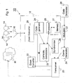
Fig. 1 is a schematic diagram of a base station incorporating the invention; and -
Fig. 2 is a diagram of a rover incorporating the invention -
Fig. 1 depicts a base station, generally indicated at 10, that operates in conjunction withrovers 12, one of which is depicted inFig. 2 . Both the base station and the rovers make use of the ranging signals transmitted by a plurality of Earth-orbitingsatellites 14. Thebase station 10 includes anantenna 16 that picks up the signals from the satellites and passes them to aGNSS receiver 18. The receiver includes adown converter 20 that translates the satellite signals to an intermediate frequency. Thedown converter 20, a correlation anddemodulation unit 22 and acode generator 24 are connected in a well known manner to synchronize carrier phase and the local codes produced by the code generator to the carrier and codes used by theindividual satellites 14, and ultimately provide the position of the base station. The base station includes aprocessor 25 and an associatedmemory 27 containing software enabling the processor to perform the functions set forth above, as well as other calculations described herein. - The
base station 10 also includes atransceiver 23, which transmits RF ranging and, as appropriate, other, signals to one of a group ofantennas 30 and receives signals picked up by theantennas 30. The RF carrier for transmissions is generated by acarrier generator 24. Amodulator 31 modulates the carrier with a local pseudo-random code that is similar to those transmitted by thesatellites 14. The local code is provided by acode generator 26. - Preferably, messages transmitted by the base station use the same bipolar phase shift modulation arrangement used by the satellites. However, this modulation, provided also by the
modulator 31, may be applied only to the quadrature phase of the carrier. The information in the messages may include information transmitted by thesatellites 14, as well as other information described herein. - The ranging signal transmissions from the base station are synchronized with the satellite system time at the location of the base station. A
synchronizer 36, for example, a phase locked loop, is provided between thetransceiver 23 and theGNSS receiver 18, to ensure that the time and frequency of the transmissions are aligned with the time and frequency of the received satellite signals. Accordingly, the rovers can utilize the ranging signals transmitted by the base station in exactly the same way they treat the signals from the orbiting satellites. The in-phase version of the carrier is unmodulated by data, and thus, its demodulated code serves as a continuous "pilot" signal to which the rovers' receivers can accurately lock, even in poor signal quality locations. - The signals received by the
antennas 30 pass from the antennas through thetransceiver 23 to a downconverter 33 in thereceiver 18. Preferably the output of theconverter 33 has the same intermediate frequency as the output of thedown converter 20 so as facilitate processing the signals from the down converter by the correlation anddemodulation unit 22. - With reference to
Fig. 2 , the details of a typical rover are exemplified by the depictedrover 12, which includes aGNSS receiver 34 that may have the same construction for GPS reception as theGPS receiver 18 in the base station. The rover also has anantenna 37 for reception of satellite signals and anantenna 38 for communications from and to thebase station 10. Aseparate down converter 41 in thereceiver 34 converts the signals received on theantenna 38, by way of atransceiver 42, to the intermediate frequency used in processing signals from thesatellites 30. The rover further includes acode generator 43, acarrier generator 44 and amodulator 45, which operate like thegenerators modulator 31 in the base station. Each rover has a unique identification, which may be incorporated in its transmissions to thebase station 10. Similarly, the base station may incorporate a rover's identification in its transmissions intended primarily for that rover. As described below, the unique identification for transmissions to the base station may be a pseudo-random code, such that the base station can readily separate the signals received from the respective rovers. Further, the base station may use the code in the received signals for rover clock error and/or rover range determination. - A
synchronizer 46, for example, a phase locked loop, is provided between thedownconverter 34 and the code andcarrier generators downconverter 41 to the reception of the base station ranging transmissions to assist in the reception of the satellite signals, as described above. - Usually each of the
rovers 12 receives signals from orbiting satellites sufficient in number to ascertain the rover's position. However, from time to time, obstructions such as foliage, man-made structures, etc., may limit the number of satellite signals that are usable by a rover to fewer than the requisite four signals. Thereceiver 34 processes the signals from thebase station 10 picked up by theantenna 38, along with the satellite signals picked up by theantenna 36. Accordingly, if therover 12 receives signals from only three satellites instead of the requisite four (or more), thebase station 10 provides the fourth ranging signal for position determination. - To cope with a rover's receipt of only two usable satellite signals, we prefer to have the
base station 10 determine the range of the rover from the base station and the rover's direction. Specifically, therover 12 returns the pseudo-random code received from the base station and the base station calculates the range to the rover by measuring the round-trip elapsed time of the code and the associated carrier phase delay. Alternatively, the rover sends a response a predetermined delay after receipt of a periodic time signal broadcast by the base station, and the base station determines the elapsed time of the transmitted code and the associated carrier phase delay in order to calculate the range. - The base station may also use the phase differences of the signals received by the respective ones of the
antennas 30, to calculate, in a known manner, the azimuthal direction of the rover. The base station then transmits this information along with the range information to therover 12. Having its GPS time and the ranges to two satellites from the usable satellite signals, and also the base station's range and known position, the rover then has sufficient data to calculate its position. - In addition to or as part of the ranging signals, the base station broadcasts messages that contain information about the satellites which are in view, as set forth above. By using this information the rovers improve their acquisition and tracking of weak satellite signals and thus enhance the accuracy of the position calculations.
- Each rover may also use the base station broadcasts to reduce clock frequency errors, by synchronizing the rover's clock to the broadcast signal, at least until sufficient satellites are visible to train the rover's clocks to the satellite transmissions. As the wavelengths of the base station's transmissions are likely longer than those from the satellites, the Doppler error due to the rover's motion will be less than that from a single satellite, and the rover can more easily train its clock to the timing information in the base station's transmission. With multiple satellites, however, the rover can correct for its motion and create a more accurate clock model using the satellite signals.
- To avoid collisions in transmissions from the
rovers 12 to thebase station 10, a time slot approach (such as TDMA) may be used, since each rover and the base station have sufficiently accurate time estimates. This will also facilitate automatic addition of additional rovers, as they will fill in blank time slots. - Alternatively, a polling procedure can be utilized, in which each
rover 12 transmits only in response to a message from thebase station 10 identifying that rover. Specifically, the base station transmits to each rover, in turn, a message that includes an identification of the rover. The rover responds and from the response, the base station calculates the information set forth above. In one polling arrangement, the rover transmits its position to the base station. The base station then selects another rover for the foregoing procedure. - The embodiments described above are half-duplex, but it is feasible to make this a full duplex system, so both the
base station 10 and therovers 12 can transmit and receive simultaneously, for example, by using different carrier frequencies. This would increase the complexity of the rovers but would provide a better time transfer capability and provide more signal energy to assist the rovers in acquiring the base station signals in poor signal environments. - It is well understood that the most significant ranging error from a terrestrial based transmission is multipath. Preferably a known multipath mitigation technique will be employed, which can reduce this error. Further, proper antenna design should be used for the base station and rover antennas, as well as proper siting of the base station antenna to attenuate reflections without attenuating the desired signals. As the range from the base station will be used by each rover in computing its position, the rover's antennas for receiving the satellite signals and the base station signals should have the same lateral position. This can be accomplished, for example, by placing a whip antenna for the base station signals in the center of a patch antenna used for the reception of satellite signals. With different frequencies of the base station and satellite signals, there should not be a problem with interference, and the rover will determine ranges to the same location. Otherwise, the rover may determine ranges to different antenna locations and include an offset that compensates for the differences in the antenna locations when determining position.
- Rather than having each rover compute its own position it is also possible for it to transmit back to the base station its raw measurement data, and have the base station perform the position calculations. The base station then transmits back to the rover the rover's position. As discussed, the base station may transmit the information on the quadrature phase of the base station ranging signal, or using other transmissions.
- With the arrangement described herein, the
base station 10 may record the positions of all of therovers 12. This information is thus available to anyone who wishes to monitor the locations and movements of the rovers. - Whenever a
rover 12 is put into, or taken out of, service, an operator can enter that information into thebase station 10, so that the base station has an up-to-date list of the rovers to be polled by it. - From the foregoing it will be apparent that many of the calculations described above can be performed in either the base station or the rovers. Further, the base station is described as using multiple antennas to receive signals transmitted by the rovers but may instead use a single antenna to achieve certain of the advantages described above. In addition, each rover may be associated with a unique identification code that is used by the base station to direct transmissions to that rover and the identification code may differ from the pseudo-random code used by the rover in transmissions to the base station.
Claims (21)
- A system for enhancing position determination by rovers (12) using a satellite ranging system to ascertain their locations, the satellite ranging system including a plurality of earth-orbiting satellites (14), the system for enhancing position determination comprising:A. a base station (10) including one or more receivers (18) for receiving and processing ranging signals from multiple earth-orbiting satellites (14) and determining information relating to satellite ranging system timing at the location of the base station (10), and a transmitter for broadcasting a ranging signal that is based on the location of the base station (10), the base station ranging signal synchronized to the satellite ranging system time at the base station (10), wherein the base station (10) includes a plurality of antennas (16);B. one or more rovers, each rover (12) including at least one receiver (34) for receiving and processing the ranging signals broadcast from the earth-orbiting satellites (14) and the ranging signal from the base station (10);
characterised in that
each rover (12) comprises a transmitter that transmits to the base station (10) a return signal in response to the ranging signal received from the base station (10), the return signal being aligned with the satellite ranging system time at the location of the rover (12), wherein the base station (10) determines the range of the rover (12) from the base station (10) and the rover's (12) direction based on the received return signal. - The system defined in claim 1 in which the base station (10) synchronizes codes and carriers of the ranging signals with codes and carriers of received satellite signals.
- The system defined in claim 2 in which the base station (10) transmits to the rovers (12) information about the earth-orbiting satellites (14) in view.
- The system defined in claim 3 wherein the base station (10) further transmits information about the characteristics of the satellite signals.
- The system defined in claim 4 wherein the base station (10) transmits the information by modulating the information onto the ranging signal.
- The system defined in claim 5 wherein the base station (10) transmits the information on a quadrature channel of the ranging signal.
- A method for enhancing position determination by rovers (12) that use a satellite ranging system for location determination, the satellite ranging system including a plurality of earth-orbiting satellites (14), the method comprising the steps of:A. providing a fixed base station (10) having a receiver for receiving ranging signals transmitted by multiple earth-orbiting satellites (14) and communication signals transmitted by the rovers (12);B. providing at the base station (10) a transceiver for transmitting ranging signals to the rovers (12), the signals being synchronized to the satellite ranging system time at the base station (10), whereby the base station (10) serves as a ranging base for the rovers' (12) calculation of location, and for receiving signals from the rovers (12);C. transmitting a timing signal from the base station (10) to the rovers (12);D. transmitting return timing signals by the respective rovers (12) in response to the timing signal received from the base station (10), the rovers (12) transmitting the return timing signals after predetermined delays; andE. using the elapsed time of the return timing transmission and the predetermined delay to calculate the range from the base station (10) to the rover (12).
- The method of claim 7 wherein the base station (10) ascertains the azimuthal direction from the base station (10) to the rover (12) and uses this information to refine the position estimate of the rover (12) to assist the rover (12) in calculating its position.
- The method of claim 7 whereinA. each timing signal transmitted by the base station (10) identifies a given rover (12); andB. each rover (12) transmits the return timing signal only in response to the receipt of the timing signal identifying that rover (12).
- The method of claim 7 wherein the respective rovers (12) transmit return timing signals in preassigned time slots.
- The method of claim 7 wherein the ranging signals transmitted by the base station:i. have the same format as the ranging signals transmitted by the orbiting satellites (14); andii. are synchronized to satellite ranging system time at the location of the base station (10).
- The method of claim 11 in which codes and carriers in the ranging signals are synchronized to codes and carriers in received satellite signals.
- The method of claim 12 in which the timing signals have the form of modulation of the ranging signals transmitted by the base station (10).
- The method of claim 7 including the step of calculating the ranging system time at the location of the rover (12) by means of two way time transfer.
- The system of claim 1 wherein
the information transmitted by the base station (10) is the ranges to the respective rovers (12). - The system of claim 1 wherein
the base station (10) receivers determine directions of the respective rovers (12) based on phase differences in the signals received from the rovers (12) at two or more of the antennas (16); and
the information transmitted by the base station (10) is the directions of the respective rovers (12). - The system of claim 16 wherein
the base station (10) receivers calculate azimuth of the respective rovers (12) based on phase differences in the signals received from the rovers (12) at two or more of the antennas (16); and
the information transmitted by the base station (10) is the azimuth of the respective rovers (12). - The system of claim 17 wherein
the base station (10) transmits rover direction information separately or as part of the ranging signal; and
the one or more rovers (12) each
receive and process ranging signals from the earth-orbiting satellites (14) and the ranging signal and direction information from the base station (10) and determine their respective positions and timing from at least the ranging signals received from the base station (10) and direction information, and
transmit to the base station signals that are aligned with satellite or base station ranging system time at the location of the rover (12). - The system of claim 18 wherein the base station receivers determine ranges to the respective rovers based on the signals received from the rovers (12) and the base station transmitter transmits the ranges to the respective rovers.
- The system of claim 19 wherein the rover receivers align rover time to the timing in the base station ranging signals to assist in reception of the satellite signals.
- The system of claim 18 wherein the plurality of antennas (16) includes an antenna for receiving satellite signals and multiple co-located antennas for receiving signals transmitted by the rover (12).
Applications Claiming Priority (2)
| Application Number | Priority Date | Filing Date | Title |
|---|---|---|---|
| US78742806P | 2006-03-30 | 2006-03-30 | |
| PCT/CA2007/000516 WO2007112559A1 (en) | 2006-03-30 | 2007-03-30 | Enhancement of gnss position determination in poor signal propagation environments |
Publications (3)
| Publication Number | Publication Date |
|---|---|
| EP1999481A1 EP1999481A1 (en) | 2008-12-10 |
| EP1999481A4 EP1999481A4 (en) | 2010-11-24 |
| EP1999481B1 true EP1999481B1 (en) | 2016-01-06 |
Family
ID=38563036
Family Applications (1)
| Application Number | Title | Priority Date | Filing Date |
|---|---|---|---|
| EP07719448.8A Active EP1999481B1 (en) | 2006-03-30 | 2007-03-30 | Enhancement of gnss position determination in poor signal propagation environments |
Country Status (4)
| Country | Link |
|---|---|
| US (1) | US7656349B2 (en) |
| EP (1) | EP1999481B1 (en) |
| CA (1) | CA2647555C (en) |
| WO (1) | WO2007112559A1 (en) |
Cited By (1)
| Publication number | Priority date | Publication date | Assignee | Title |
|---|---|---|---|---|
| CN110146906A (en) * | 2019-05-23 | 2019-08-20 | 中国科学院国家授时中心 | Remote time transmission method based on single poor carrier phase observation data |
Families Citing this family (13)
| Publication number | Priority date | Publication date | Assignee | Title |
|---|---|---|---|---|
| US8169982B2 (en) | 2005-08-10 | 2012-05-01 | Qualcomm Incorporated | Method and apparatus for creating a fingerprint for a wireless network |
| US8159397B2 (en) * | 2006-03-30 | 2012-04-17 | Novatel Inc. | System for determining position using two way time transfer signals |
| US9137745B2 (en) | 2007-10-12 | 2015-09-15 | Qualcomm Incorporated | System and method to locate femto cells with passive assistance from a macro cellular wireless network |
| CA2704264C (en) | 2007-11-02 | 2015-03-17 | Novatel Inc. | System and method for distributing accurate time and frequency over a network |
| US9253653B2 (en) | 2007-11-09 | 2016-02-02 | Qualcomm Incorporated | Access point configuration based on received access point signals |
| CN101855566B (en) * | 2007-11-13 | 2014-06-04 | 诺瓦特公司 | System and method for determining position over a network |
| CN103777217B (en) | 2008-05-22 | 2017-03-01 | 诺瓦特公司 | For reducing GNSS receiver and the system of primary positioning time |
| US20100164789A1 (en) * | 2008-12-30 | 2010-07-01 | Gm Global Technology Operations, Inc. | Measurement Level Integration of GPS and Other Range and Bearing Measurement-Capable Sensors for Ubiquitous Positioning Capability |
| US8838096B2 (en) | 2009-05-29 | 2014-09-16 | Qualcomm Incorporated | Non-macro cell search integrated with macro-cellular RF carrier monitoring |
| US8923892B2 (en) | 2010-05-14 | 2014-12-30 | Qualcomm Incorporated | Method and apparatus for updating femtocell proximity information |
| US8681045B2 (en) * | 2010-07-09 | 2014-03-25 | Intel Mobile Communications GmbH | Hybrid satellite positioning receiver |
| US10690777B2 (en) * | 2014-07-31 | 2020-06-23 | Fraunhofer-Gesellschaft Zur Foerderung Der Angewandten Forschung E.V. | Multi-antenna-GNSS receiver-system to raise the probability of line of sight |
| US11432109B2 (en) | 2019-11-27 | 2022-08-30 | Qualcomm Incorporated | Positioning of vehicles and pedestrians leveraging ranging signal |
Family Cites Families (12)
| Publication number | Priority date | Publication date | Assignee | Title |
|---|---|---|---|---|
| US3742498A (en) * | 1970-05-06 | 1973-06-26 | Itt | Synchronization and position location system |
| FR2735240B1 (en) * | 1995-06-06 | 1998-01-30 | Soc Et Rech Et Const Electroni | METHOD AND DEVICE FOR THE PRECISE DETERMINATION OF A MASK POINT BY SATELLITE RADIOLOCATION. |
| EP0877950A4 (en) | 1996-02-01 | 2000-01-26 | Stanford Telecomm Inc | Radio navigation system using out-of-band pseudolites |
| US5928306A (en) * | 1996-08-22 | 1999-07-27 | Trimble Navigation Limited | Method and apparatus for automated differential GPS processing |
| US5786773A (en) * | 1996-10-02 | 1998-07-28 | The Boeing Company | Local-area augmentation system for satellite navigation precision-approach system |
| US6101178A (en) | 1997-07-10 | 2000-08-08 | Ksi Inc. | Pseudolite-augmented GPS for locating wireless telephones |
| US6268824B1 (en) * | 1998-09-18 | 2001-07-31 | Topcon Positioning Systems, Inc. | Methods and apparatuses of positioning a mobile user in a system of satellite differential navigation |
| GB9920286D0 (en) * | 1999-08-27 | 1999-10-27 | Roke Manor Research | Improvements in or relating to satellite navigation |
| US6560535B2 (en) | 2000-01-05 | 2003-05-06 | The Johns Hopkins University | Global positioning system roadside integrated precision positioning system |
| US6882314B2 (en) * | 2000-01-24 | 2005-04-19 | Novariant, Inc. | Carrier-based differential-position determination using multi-frequency pseudolites |
| US6556942B1 (en) * | 2000-09-29 | 2003-04-29 | Ut-Battelle, Llc | Short range spread-spectrum radiolocation system and method |
| CA2499954C (en) | 2002-09-23 | 2011-11-01 | Topcon Gps Llc | Position estimation using a network of global-positioning receivers |
-
2007
- 2007-03-30 CA CA2647555A patent/CA2647555C/en active Active
- 2007-03-30 WO PCT/CA2007/000516 patent/WO2007112559A1/en active Application Filing
- 2007-03-30 EP EP07719448.8A patent/EP1999481B1/en active Active
- 2007-03-30 US US11/694,368 patent/US7656349B2/en active Active
Cited By (1)
| Publication number | Priority date | Publication date | Assignee | Title |
|---|---|---|---|---|
| CN110146906A (en) * | 2019-05-23 | 2019-08-20 | 中国科学院国家授时中心 | Remote time transmission method based on single poor carrier phase observation data |
Also Published As
| Publication number | Publication date |
|---|---|
| WO2007112559A1 (en) | 2007-10-11 |
| EP1999481A1 (en) | 2008-12-10 |
| EP1999481A4 (en) | 2010-11-24 |
| US7656349B2 (en) | 2010-02-02 |
| US20070241960A1 (en) | 2007-10-18 |
| CA2647555C (en) | 2014-02-11 |
| CA2647555A1 (en) | 2007-10-11 |
Similar Documents
| Publication | Publication Date | Title |
|---|---|---|
| EP1999481B1 (en) | Enhancement of gnss position determination in poor signal propagation environments | |
| US7039421B2 (en) | System for determining the position of an object | |
| EP1735634B1 (en) | Position detection with frequency smoothing | |
| CA2066831C (en) | Vehicle tracking system employing global positioning system (gps) satellites | |
| US7616682B2 (en) | Method and device for chronologically synchronizing a location network | |
| US6646603B2 (en) | Method of providing an estimate of a location | |
| US9851429B2 (en) | Terrestrial position and timing system | |
| US5995043A (en) | Aircraft satellite navigation precision-approach system including CDMA datalink | |
| CA2784617C (en) | System for determining position using two way time transfer signals | |
| US20130063302A1 (en) | Coding in a wide area positioning system (waps) | |
| US20040008138A1 (en) | Apparatus and method of position determination using shared information | |
| AU2016202845A1 (en) | Coding in a wide area positioning system (WAPS) | |
| US7403155B2 (en) | Method for the accelerated acquisition of satellite signals | |
| WO2021183067A1 (en) | A gnss repeater architecture and location finding method for indoor positioning systems using lower frequencies than gnss signals |
Legal Events
| Date | Code | Title | Description |
|---|---|---|---|
| PUAI | Public reference made under article 153(3) epc to a published international application that has entered the european phase |
Free format text: ORIGINAL CODE: 0009012 |
|
| 17P | Request for examination filed |
Effective date: 20080922 |
|
| AK | Designated contracting states |
Kind code of ref document: A1 Designated state(s): AT BE BG CH CY CZ DE DK EE ES FI FR GB GR HU IE IS IT LI LT LU LV MC MT NL PL PT RO SE SI SK TR |
|
| AX | Request for extension of the european patent |
Extension state: AL BA HR MK RS |
|
| RIN1 | Information on inventor provided before grant (corrected) |
Inventor name: FELLER, WALTER J. |
|
| A4 | Supplementary search report drawn up and despatched |
Effective date: 20101021 |
|
| 17Q | First examination report despatched |
Effective date: 20110811 |
|
| REG | Reference to a national code |
Ref country code: DE Ref legal event code: R079 Ref document number: 602007044450 Country of ref document: DE Free format text: PREVIOUS MAIN CLASS: G01S0005140000 Ipc: G01S0019050000 |
|
| GRAP | Despatch of communication of intention to grant a patent |
Free format text: ORIGINAL CODE: EPIDOSNIGR1 |
|
| RIC1 | Information provided on ipc code assigned before grant |
Ipc: G01S 19/25 20100101ALI20150625BHEP Ipc: G01S 19/05 20100101AFI20150625BHEP Ipc: G01S 19/06 20100101ALI20150625BHEP Ipc: G01S 19/23 20100101ALI20150625BHEP Ipc: G01S 19/12 20100101ALI20150625BHEP |
|
| INTG | Intention to grant announced |
Effective date: 20150723 |
|
| GRAS | Grant fee paid |
Free format text: ORIGINAL CODE: EPIDOSNIGR3 |
|
| GRAA | (expected) grant |
Free format text: ORIGINAL CODE: 0009210 |
|
| AK | Designated contracting states |
Kind code of ref document: B1 Designated state(s): AT BE BG CH CY CZ DE DK EE ES FI FR GB GR HU IE IS IT LI LT LU LV MC MT NL PL PT RO SE SI SK TR |
|
| AX | Request for extension of the european patent |
Extension state: AL BA HR MK RS |
|
| REG | Reference to a national code |
Ref country code: GB Ref legal event code: FG4D |
|
| REG | Reference to a national code |
Ref country code: CH Ref legal event code: EP |
|
| REG | Reference to a national code |
Ref country code: CH Ref legal event code: NV Representative=s name: FELBER AND PARTNER AG, CH |
|
| REG | Reference to a national code |
Ref country code: IE Ref legal event code: FG4D |
|
| REG | Reference to a national code |
Ref country code: AT Ref legal event code: REF Ref document number: 769302 Country of ref document: AT Kind code of ref document: T Effective date: 20160215 |
|
| REG | Reference to a national code |
Ref country code: DE Ref legal event code: R096 Ref document number: 602007044450 Country of ref document: DE |
|
| REG | Reference to a national code |
Ref country code: FR Ref legal event code: PLFP Year of fee payment: 10 |
|
| REG | Reference to a national code |
Ref country code: LT Ref legal event code: MG4D |
|
| REG | Reference to a national code |
Ref country code: NL Ref legal event code: MP Effective date: 20160106 |
|
| REG | Reference to a national code |
Ref country code: AT Ref legal event code: MK05 Ref document number: 769302 Country of ref document: AT Kind code of ref document: T Effective date: 20160106 |
|
| PG25 | Lapsed in a contracting state [announced via postgrant information from national office to epo] |
Ref country code: NL Free format text: LAPSE BECAUSE OF FAILURE TO SUBMIT A TRANSLATION OF THE DESCRIPTION OR TO PAY THE FEE WITHIN THE PRESCRIBED TIME-LIMIT Effective date: 20160106 |
|
| PG25 | Lapsed in a contracting state [announced via postgrant information from national office to epo] |
Ref country code: IT Free format text: LAPSE BECAUSE OF FAILURE TO SUBMIT A TRANSLATION OF THE DESCRIPTION OR TO PAY THE FEE WITHIN THE PRESCRIBED TIME-LIMIT Effective date: 20160106 Ref country code: ES Free format text: LAPSE BECAUSE OF FAILURE TO SUBMIT A TRANSLATION OF THE DESCRIPTION OR TO PAY THE FEE WITHIN THE PRESCRIBED TIME-LIMIT Effective date: 20160106 Ref country code: GR Free format text: LAPSE BECAUSE OF FAILURE TO SUBMIT A TRANSLATION OF THE DESCRIPTION OR TO PAY THE FEE WITHIN THE PRESCRIBED TIME-LIMIT Effective date: 20160407 Ref country code: FI Free format text: LAPSE BECAUSE OF FAILURE TO SUBMIT A TRANSLATION OF THE DESCRIPTION OR TO PAY THE FEE WITHIN THE PRESCRIBED TIME-LIMIT Effective date: 20160106 |
|
| PG25 | Lapsed in a contracting state [announced via postgrant information from national office to epo] |
Ref country code: PL Free format text: LAPSE BECAUSE OF FAILURE TO SUBMIT A TRANSLATION OF THE DESCRIPTION OR TO PAY THE FEE WITHIN THE PRESCRIBED TIME-LIMIT Effective date: 20160106 Ref country code: IS Free format text: LAPSE BECAUSE OF FAILURE TO SUBMIT A TRANSLATION OF THE DESCRIPTION OR TO PAY THE FEE WITHIN THE PRESCRIBED TIME-LIMIT Effective date: 20160506 Ref country code: SE Free format text: LAPSE BECAUSE OF FAILURE TO SUBMIT A TRANSLATION OF THE DESCRIPTION OR TO PAY THE FEE WITHIN THE PRESCRIBED TIME-LIMIT Effective date: 20160106 Ref country code: LT Free format text: LAPSE BECAUSE OF FAILURE TO SUBMIT A TRANSLATION OF THE DESCRIPTION OR TO PAY THE FEE WITHIN THE PRESCRIBED TIME-LIMIT Effective date: 20160106 Ref country code: LV Free format text: LAPSE BECAUSE OF FAILURE TO SUBMIT A TRANSLATION OF THE DESCRIPTION OR TO PAY THE FEE WITHIN THE PRESCRIBED TIME-LIMIT Effective date: 20160106 Ref country code: PT Free format text: LAPSE BECAUSE OF FAILURE TO SUBMIT A TRANSLATION OF THE DESCRIPTION OR TO PAY THE FEE WITHIN THE PRESCRIBED TIME-LIMIT Effective date: 20160506 Ref country code: AT Free format text: LAPSE BECAUSE OF FAILURE TO SUBMIT A TRANSLATION OF THE DESCRIPTION OR TO PAY THE FEE WITHIN THE PRESCRIBED TIME-LIMIT Effective date: 20160106 |
|
| REG | Reference to a national code |
Ref country code: DE Ref legal event code: R097 Ref document number: 602007044450 Country of ref document: DE |
|
| PG25 | Lapsed in a contracting state [announced via postgrant information from national office to epo] |
Ref country code: DK Free format text: LAPSE BECAUSE OF FAILURE TO SUBMIT A TRANSLATION OF THE DESCRIPTION OR TO PAY THE FEE WITHIN THE PRESCRIBED TIME-LIMIT Effective date: 20160106 Ref country code: MC Free format text: LAPSE BECAUSE OF FAILURE TO SUBMIT A TRANSLATION OF THE DESCRIPTION OR TO PAY THE FEE WITHIN THE PRESCRIBED TIME-LIMIT Effective date: 20160106 Ref country code: EE Free format text: LAPSE BECAUSE OF FAILURE TO SUBMIT A TRANSLATION OF THE DESCRIPTION OR TO PAY THE FEE WITHIN THE PRESCRIBED TIME-LIMIT Effective date: 20160106 Ref country code: LU Free format text: LAPSE BECAUSE OF FAILURE TO SUBMIT A TRANSLATION OF THE DESCRIPTION OR TO PAY THE FEE WITHIN THE PRESCRIBED TIME-LIMIT Effective date: 20160330 |
|
| PLBE | No opposition filed within time limit |
Free format text: ORIGINAL CODE: 0009261 |
|
| STAA | Information on the status of an ep patent application or granted ep patent |
Free format text: STATUS: NO OPPOSITION FILED WITHIN TIME LIMIT |
|
| PG25 | Lapsed in a contracting state [announced via postgrant information from national office to epo] |
Ref country code: RO Free format text: LAPSE BECAUSE OF FAILURE TO SUBMIT A TRANSLATION OF THE DESCRIPTION OR TO PAY THE FEE WITHIN THE PRESCRIBED TIME-LIMIT Effective date: 20160106 Ref country code: CZ Free format text: LAPSE BECAUSE OF FAILURE TO SUBMIT A TRANSLATION OF THE DESCRIPTION OR TO PAY THE FEE WITHIN THE PRESCRIBED TIME-LIMIT Effective date: 20160106 Ref country code: SK Free format text: LAPSE BECAUSE OF FAILURE TO SUBMIT A TRANSLATION OF THE DESCRIPTION OR TO PAY THE FEE WITHIN THE PRESCRIBED TIME-LIMIT Effective date: 20160106 |
|
| 26N | No opposition filed |
Effective date: 20161007 |
|
| REG | Reference to a national code |
Ref country code: IE Ref legal event code: MM4A |
|
| PG25 | Lapsed in a contracting state [announced via postgrant information from national office to epo] |
Ref country code: IE Free format text: LAPSE BECAUSE OF NON-PAYMENT OF DUE FEES Effective date: 20160330 |
|
| PG25 | Lapsed in a contracting state [announced via postgrant information from national office to epo] |
Ref country code: SI Free format text: LAPSE BECAUSE OF FAILURE TO SUBMIT A TRANSLATION OF THE DESCRIPTION OR TO PAY THE FEE WITHIN THE PRESCRIBED TIME-LIMIT Effective date: 20160106 Ref country code: BG Free format text: LAPSE BECAUSE OF FAILURE TO SUBMIT A TRANSLATION OF THE DESCRIPTION OR TO PAY THE FEE WITHIN THE PRESCRIBED TIME-LIMIT Effective date: 20160406 |
|
| REG | Reference to a national code |
Ref country code: FR Ref legal event code: PLFP Year of fee payment: 11 |
|
| PG25 | Lapsed in a contracting state [announced via postgrant information from national office to epo] |
Ref country code: MT Free format text: LAPSE BECAUSE OF FAILURE TO SUBMIT A TRANSLATION OF THE DESCRIPTION OR TO PAY THE FEE WITHIN THE PRESCRIBED TIME-LIMIT Effective date: 20160106 |
|
| REG | Reference to a national code |
Ref country code: FR Ref legal event code: PLFP Year of fee payment: 12 |
|
| PG25 | Lapsed in a contracting state [announced via postgrant information from national office to epo] |
Ref country code: CY Free format text: LAPSE BECAUSE OF FAILURE TO SUBMIT A TRANSLATION OF THE DESCRIPTION OR TO PAY THE FEE WITHIN THE PRESCRIBED TIME-LIMIT Effective date: 20160106 Ref country code: HU Free format text: LAPSE BECAUSE OF FAILURE TO SUBMIT A TRANSLATION OF THE DESCRIPTION OR TO PAY THE FEE WITHIN THE PRESCRIBED TIME-LIMIT; INVALID AB INITIO Effective date: 20070330 |
|
| PG25 | Lapsed in a contracting state [announced via postgrant information from national office to epo] |
Ref country code: TR Free format text: LAPSE BECAUSE OF FAILURE TO SUBMIT A TRANSLATION OF THE DESCRIPTION OR TO PAY THE FEE WITHIN THE PRESCRIBED TIME-LIMIT Effective date: 20160106 Ref country code: MT Free format text: LAPSE BECAUSE OF FAILURE TO SUBMIT A TRANSLATION OF THE DESCRIPTION OR TO PAY THE FEE WITHIN THE PRESCRIBED TIME-LIMIT Effective date: 20160331 |
|
| PGFP | Annual fee paid to national office [announced via postgrant information from national office to epo] |
Ref country code: BE Payment date: 20200327 Year of fee payment: 14 |
|
| REG | Reference to a national code |
Ref country code: BE Ref legal event code: MM Effective date: 20210331 |
|
| PG25 | Lapsed in a contracting state [announced via postgrant information from national office to epo] |
Ref country code: BE Free format text: LAPSE BECAUSE OF NON-PAYMENT OF DUE FEES Effective date: 20210331 |
|
| PGFP | Annual fee paid to national office [announced via postgrant information from national office to epo] |
Ref country code: FR Payment date: 20230327 Year of fee payment: 17 |
|
| PGFP | Annual fee paid to national office [announced via postgrant information from national office to epo] |
Ref country code: GB Payment date: 20230327 Year of fee payment: 17 Ref country code: DE Payment date: 20230329 Year of fee payment: 17 |
|
| PGFP | Annual fee paid to national office [announced via postgrant information from national office to epo] |
Ref country code: CH Payment date: 20230402 Year of fee payment: 17 |