EP1997243B1 - Method and apparatus for spreading channel code selection - Google Patents
Method and apparatus for spreading channel code selection Download PDFInfo
- Publication number
- EP1997243B1 EP1997243B1 EP07757173.5A EP07757173A EP1997243B1 EP 1997243 B1 EP1997243 B1 EP 1997243B1 EP 07757173 A EP07757173 A EP 07757173A EP 1997243 B1 EP1997243 B1 EP 1997243B1
- Authority
- EP
- European Patent Office
- Prior art keywords
- code
- remote unit
- spreading channel
- network node
- group
- Prior art date
- Legal status (The legal status is an assumption and is not a legal conclusion. Google has not performed a legal analysis and makes no representation as to the accuracy of the status listed.)
- Active
Links
- 230000007480 spreading Effects 0.000 title claims description 87
- 238000000034 method Methods 0.000 title claims description 26
- 230000011664 signaling Effects 0.000 claims description 20
- 238000000638 solvent extraction Methods 0.000 claims description 12
- 238000012545 processing Methods 0.000 claims description 10
- 230000008901 benefit Effects 0.000 description 9
- 238000004891 communication Methods 0.000 description 9
- 238000010586 diagram Methods 0.000 description 9
- 238000005516 engineering process Methods 0.000 description 9
- 238000005192 partition Methods 0.000 description 4
- 230000000694 effects Effects 0.000 description 3
- 238000005259 measurement Methods 0.000 description 3
- 230000001419 dependent effect Effects 0.000 description 2
- 238000013461 design Methods 0.000 description 2
- 238000004519 manufacturing process Methods 0.000 description 2
- 238000012986 modification Methods 0.000 description 2
- 230000004048 modification Effects 0.000 description 2
- 230000008569 process Effects 0.000 description 2
- 230000008685 targeting Effects 0.000 description 2
- 230000009286 beneficial effect Effects 0.000 description 1
- 238000003339 best practice Methods 0.000 description 1
- 230000005540 biological transmission Effects 0.000 description 1
- 230000008859 change Effects 0.000 description 1
- 238000004590 computer program Methods 0.000 description 1
- 230000001934 delay Effects 0.000 description 1
- 238000009795 derivation Methods 0.000 description 1
- 238000011161 development Methods 0.000 description 1
- 230000006870 function Effects 0.000 description 1
- 230000004044 response Effects 0.000 description 1
- 238000012163 sequencing technique Methods 0.000 description 1
Images
Classifications
-
- H—ELECTRICITY
- H04—ELECTRIC COMMUNICATION TECHNIQUE
- H04J—MULTIPLEX COMMUNICATION
- H04J13/00—Code division multiplex systems
- H04J13/16—Code allocation
-
- H—ELECTRICITY
- H04—ELECTRIC COMMUNICATION TECHNIQUE
- H04W—WIRELESS COMMUNICATION NETWORKS
- H04W72/00—Local resource management
- H04W72/04—Wireless resource allocation
-
- H—ELECTRICITY
- H04—ELECTRIC COMMUNICATION TECHNIQUE
- H04W—WIRELESS COMMUNICATION NETWORKS
- H04W72/00—Local resource management
- H04W72/04—Wireless resource allocation
- H04W72/044—Wireless resource allocation based on the type of the allocated resource
- H04W72/0453—Resources in frequency domain, e.g. a carrier in FDMA
-
- H—ELECTRICITY
- H04—ELECTRIC COMMUNICATION TECHNIQUE
- H04W—WIRELESS COMMUNICATION NETWORKS
- H04W74/00—Wireless channel access, e.g. scheduled or random access
- H04W74/08—Non-scheduled or contention based access, e.g. random access, ALOHA, CSMA [Carrier Sense Multiple Access]
Definitions
- the present invention relates generally to communications and, in particular, to spreading channel code selection in communication systems.
- WO-A1-0193462 provides a method of selecting a random access channel (RACH), based on access service class of a user equipment (UE).
- RACH random access channel
- EP-A1-0993214 shows an allocation of two groups of random access slots on the basis of respective priority classes.
- FIGs. 1-5 Both the description and the illustrations have been drafted with the intent to enhance understanding. For example, the dimensions of some of the figure elements may be exaggerated relative to other elements, and well-known elements that are beneficial or even necessary to a commercially successful implementation may not be depicted so that a less obstructed and a more clear presentation of embodiments may be achieved. In addition, unless specifically indicated, the order and grouping of signaling is not a limitation of other embodiments that may lie within the scope of the claims.
- Various embodiments are described which may serve to improve spreading channel code selection in wireless technologies that employ two-stage ranging. For example, some of the embodiments enable a number of spreading codes to be reused at each network node, potentially increasing the number of codes available to each remote unit and thereby reducing the collision rate.
- remote units select a spreading channel code based on one or more considerations such as at least one of pilot signal strength and remote unit location. Remote units may also base this selection of a spreading channel code on one or more additional considerations, i.e. at least one of a remote unit mobility level, and a priority class associated with the remote unit.
- network nodes can partition the spreading codes into groups and then assign link bandwidth to remote units based on the group associated with the code selected by that remote unit.
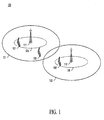
- FIGs. 1 and 2 depict a wireless communication system 100 in accordance with multiple embodiments of the present invention.
- standards bodies such as OMA (Open Mobile Alliance), 3GPP (3rd Generation Partnership Project), 3GPP2 (3rd Generation Partnership Project 2) and IEEE (Institute of Electrical and Electronics Engineers) 802 are developing standards specifications for wireless telecommunications systems.
- Communication system 100 represents a system having an architecture in accordance with one or more of the 3GPP2 technologies, suitably modified to implement the present invention.
- Alternative embodiments of the present invention may be implemented in communication systems that employ other or additional technologies such as, but not limited to, those described in the 3GPP specifications and/or those described in the IEEE's 802.xx specifications (e.g., 802.16).
- Network 130 may represent an IP (internet protocol) network or, in combination with network nodes 111 and 112, a radio access network (RAN) or access network (AN).
- IP internet protocol
- RAN radio access network
- AN access network
- network nodes 111 and 112 may comprise base transceiver stations (BTSs), access points (APs), and/or higher order devices such as base stations (BSs) (which include BTSs and base site controllers (BSCs)) and WLAN (wireless local area network) stations (which include APs, AP controllers / switches, and/or WLAN switches); however, none of these devices are specifically shown in FIGs. 1 or 2 .
- BTSs base transceiver stations
- APs access points
- BSs base stations
- BSCs base site controllers
- WLAN wireless local area network stations
- processing units are known to comprise basic components such as, but neither limited to nor necessarily requiring, microprocessors, microcontrollers, memory devices, application-specific integrated circuits (ASICs), and/or logic circuitry.
- ASICs application-specific integrated circuits
- Such components are typically adapted to implement algorithms and/or protocols that have been expressed using high-level design languages or descriptions, expressed using computer instructions, expressed using signaling flow diagrams, and/or expressed using logic flow diagrams.
- remote unit 101 represents a known device that has been adapted, in accordance with the description herein, to implement multiple embodiments of the present invention.
- network aspects may be implemented in and across various physical components and none are necessarily limited to single platform implementations.
- the network aspects may be implemented in or across one or more network devices, such as in network node 111 or across one or more network nodes and/or network 130.
- Processing unit 105 of remote unit 101 receives signaling from network node 111 via wireless interface 150 and transceiver 107.
- the received signaling is pilot information conveyed via a pilot channel of network node 111.
- prior art remote units randomly select a spreading channel code to use with their initial ranging signal.
- processing unit 105 of remote unit 101 selects a spreading channel code based on one or more considerations, depending on the particular embodiment. These considerations include at least one of the signal strength of the received signaling, and the current location of the remote unit. Remote units may also base this selection of a spreading channel code on one or more additional considerations, i.e.
- processing unit 105 then transmits, via transceiver 107 and wireless interface 150, an initial access signal using the spreading channel code selected.
- This initial access signal may take the form of a ranging signal, for example, or other technology-dependent signaling required access the network node.
- the spreading channel codes may be orthogonal or quasi-orthogonal, although they need not be either, such as the spreading codes specified in IEEE 802.16e.
- the spreading channel codes may be based on Chu sequences as described in US2007165567, filed January 17, 2006 , entitled "PREAMBLE SEQUENCING FOR RANDOM ACCESS CHANNEL IN A COMMUNICATION SYSTEM".
- network node 111 partitions the spreading channel codes that it makes available to remote units into code groups and transmits an indication of both the spreading channel codes available for use and the code group with which each is associated. This is information may be broadcast and received by remote unit 101 via a pilot channel of network node 111. Obviously, there are a great many ways to indicate the spreading channel codes and their associated code groups to remote units. The specific format of this signaling will, of course, depend upon how much information the remote units already have regarding the nature and identity of the code set used system-wide and used by the particular network node itself.
- remote unit 101 receives signaling that indicates which spreading channel codes may be used by the remote unit for accessing network node 111 and the associated groupings of the codes. In these embodiments, then, processing unit 105 determines a particular code group from which to select a spreading channel code to use. Depending on the embodiment, remote unit 101 determines a particular code group based on one or more considerations. These considerations comprise a received signal strength (the pilot signal strength, e.g.) from network node 111 and the current location of remote unit 101. Remote unit 101 may also determine the particular code group based on one or more additional considerations, i.e. at least one of the current mobility level of remote unit 101, and / or a current priority class associated with remote unit 101.
- considerations comprise a received signal strength (the pilot signal strength, e.g.) from network node 111 and the current location of remote unit 101.
- Remote unit 101 may also determine the particular code group based on one or more additional considerations, i.e. at least one of the current mobility level
- This determination may in addition be guided by the remote unit characteristics that individual code groups are intended to target. For example, one code group may be targeted for remote units that are associated with a particular priority class, i.e. a particular level of service. This could allow codes to be "set aside” for users who have purchased a premium level service or users who are involved in responding to emergencies, for example.
- a particular priority class i.e. a particular level of service. This could allow codes to be "set aside" for users who have purchased a premium level service or users who are involved in responding to emergencies, for example.
- Code groups could also be targeted for remote units in a particular area. For example, a code group might target remote units inside (or outside) region 125 around network node 111. Or a code group may target an area of particular interest such as that around a stadium, convention center, highway, shopping center, auditorium, conference room, etc. Code groups could in addition target remote units having a particular level of mobility. For example, one code group may target low-mobility units while another targets high-mobility units.
- a characteristic that individual code groups may be intended to target is remote unit received signal strength, this being of signaling from the network node such as pilot signaling that is received by the remote unit.
- Signal strength is used throughout this description to generically refer to the various forms of signal measurement that are used such as signal quality measurements, measurements for CQI (channel quality indicator), and/or unique metrics derived from various combinations of both).
- One example of code groups targeting remote unit received signal strength would be for network node 111 to target one code group for units that have a received signal strength above a particular threshold and another code group for units that have a received signal strength below the particular threshold.
- network node 111 could target one code group for coverage region 125 (roughly) and another for the remainder of coverage area 121. (Note that a similar effect could be achieved using remote unit location, as described above.) Partitioning the spreading channel codes into code groups that are targeted for particular coverage regions can enable greater code reuse than is believed available today. For example, the spreading channel codes of one or more code groups targeting wireless coverage region 125, for instance, can be reused by network nodes with wireless coverage areas adjacent to network node 111. Thus, since interference is not a problem between coverage regions 125 and 126, network nodes 111 and 112 can reuse the spreading channel codes targeted for these regions. Potentially, then, for a subset of the spreading channel codes a 1:1 reuse pattern could be used.
- network node 111 may monitor a system loading level and partition the spreading channel codes into code groups based on the current system load. For example, network node 111 may partition the spreading channel codes into more code groups when the system loading level is greater than a loading threshold.
- system loading level indicators include the number of collisions per code/code group, the number of transmissions per code/code group (equivalently utilization of codes/code groups), recent changes in the number of users attached to the cell in different cell groups (predicting/anticipating a significant change in pattern), etc.
- the benefit sought by considering the level of system loading is that by partitioning more code groups and having the remote unit selecting the appropriate code group, the system can save capacity by using information from the remote unit indicating how large a resource assignment it needs.
- the network will still end up doing a fair bit of over assignment of resources for mobiles which are very close to the network node, as the network may think that they are as far away as halfway out within the cell.
- partitioning 10 different groups then the network can know that the user who is very near the tower is within the closest 1/10 or so of the cell/sector and thus can use an even smaller assignment.
- the downside of breaking the codes into more groups is that of potentially creating more collisions within one group while another group is under-utilized. However, this can be addressed by dividing the unit among code groups in different time intervals.
- remote unit 101 determines a particular code group based on one or more of the considerations of: a received signal strength from network node 111 and the current location of remote unit 101.
- Remote unit 101 may also determine the particular code group based on one or more additional considerations, i.e. at least one of the current mobility level of remote unit 101, and / or a current priority class associated with remote unit 101. As discussed above, this determination may be guided by the remote unit characteristics that individual code groups are intended to target.
- Network node 111 may also indicate to remote unit 101, in addition to the codes and the code groupings, what characteristics the code groups are intended to target.
- remote unit 101 determines a particular code group from which to select a spreading channel code.
- processing unit 105 simply selects a spreading channel code randomly from the spreading channel codes associated with the determined group.
- the selection of a spreading channel code based on various considerations may be performed by determining a code group, based on the particular considerations, and then selecting, perhaps randomly, a spreading channel code from the determined code group.
- remote unit 101 considers the applicable characteristics or combination of characteristics that the available code groups target to determine a code group from which to select a code. For example, remote unit 101 may determine to select from one code group because of the remote unit's current location (per GPS, e.g.). In another embodiment, remote unit 101 may determine to select from a particular code group because the pilot signal strength of network node 111 is greater than a threshold and, in this example, an additional consideration to be applied to the determination may be that remote unit 101 currently has a low level of mobility. Another code group may be determined for selection in the case that the pilot signal strength is below the threshold. This is just one example of the many possible combinations of characteristics that code groups might target to effect a partitioning of the spreading codes.
- remote units may not be locked into selecting a spreading channel code from the code group targeted by the applicable remote unit characteristics. For example, remote unit 101 may determine the code group that applies to its current situation, select a code to use from that code group, and then determine that the code selected is being used by another device. In such a case, remote unit 101 may select another code from the determined code group or may select a code from another code group altogether.
- the spreading channel codes that are partitioned into groups, while unique as codes, may share a common modulation and coding type. Thus, when a remote unit, in this case, selects a spreading channel code, it is not selecting a level of redundancy or a type of modulation / data rate.
- the remote unit will select the spreading channel code and a time period for using the spreading channel code.
- the remote unit selects a code-time combination (e.g., a code and a start time) from a group of code-time combinations.
- a code-time combination e.g., a code and a start time
- the available code-time combinations are partitioned into groups just as the codes alone would be, except that the same codes may be in different groups but associated with different time periods for use. Determination of a group of code-time combinations from which to select could occur as described herein for code groups.
- network node 111 may assign an amount of link bandwidth (forward and/or reverse link bandwidth) to the remote unit based on the code group of the spreading channel code used. For example, in a case in which the code group has been targeted for a level of signal strength of a signal received by the remote unit greater than a threshold and the remote unit uses a spreading channel code from that code group, the network node may assign a smaller amount of link bandwidth to the remote unit than would be otherwise assigned. Here, the network node may assume that the smaller amount of link bandwidth will be sufficient since the remote unit has signal strength greater than the threshold, as indicated by the spreading channel code the remote unit used. Potentially then, using this technique, less bandwidth may be used in certain situations, improving system capacity.
- link bandwidth forward and/or reverse link bandwidth
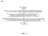
- FIG. 3 is a logic flow diagram of functionality performed by a network in accordance with multiple embodiments of the present invention.
- Logic flow 300 begins (301) with the network partitioning (303) a plurality of spreading channel codes into a plurality of code groups. The network then transmits (305) signaling that indicates the code groupings produced by the partitioning and receives an initial access signal from a remote unit using a spreading channel code from a code group of the plurality of code groups. Logic flow 300 then ends (309).
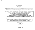
- FIG. 4 is a logic flow diagram of functionality performed by a remote unit in accordance with multiple embodiments of the present invention.
- Logic flow 400 begins (401) when a remote unit receives (403) signaling from a network node.
- the remote unit selects (405) a spreading channel code based on at least one characteristic from a group of a signal strength of the received signaling, a current location of the remote unit, a current mobility level of the remote unit, and a current priority class associated with the remote unit.
- the remote unit transmits (407) an initial access signal using the spreading channel code.
- Logic flow 400 then ends (409).
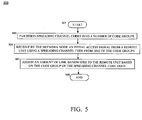
- FIG. 5 is a logic flow diagram of functionality performed by a network in accordance with multiple embodiments of the present invention.
- Logic flow 500 begins (501) with the network partitioning (503) a plurality of spreading channel codes into a plurality of code groups.
- the network receives (505) an initial access signal from a remote unit using a spreading channel code from a code group of the plurality of code groups.
- the network assigns (507) an amount of link bandwidth to the remote unit based on the code group of the spreading channel code used by the remote unit.
- Logic flow 500 then ends (509).
- the term "comprises,” “comprising,” or any other variation thereof is intended to refer to a non-exclusive inclusion, such that a process, method, article of manufacture, or apparatus that comprises a list of elements does not include only those elements in the list, but may include other elements not expressly listed or inherent to such process, method, article of manufacture, or apparatus.
- the terms a or an, as used herein, are defined as one or more than one.
- the term plurality, as used herein, is defined as two or more than two.
- the term another, as used herein is defined as at least a second or more.
- the terms including and/or having, as used herein, are defined as comprising (i.e., open language).
- Coupled is defined as connected, although not necessarily directly, and not necessarily mechanically.
- Terminology derived from the word "indicating” e.g., "indicates” and “indication" are intended to encompass all the various techniques available for communicating or referencing the object being indicated.
- Some, but not all examples of techniques available for communicating or referencing the object being indicated include the conveyance of the object being indicated, the conveyance of an identifier of the object being indicated, the conveyance of information used to generate the object being indicated, the conveyance of some part or portion of the object being indicated, the conveyance of some derivation of the object being indicated, and the conveyance of some symbol representing the object being indicated.
- program is defined as a sequence of instructions designed for execution on a computer system.
- This sequence of instructions may include, but is not limited to, a subroutine, a function, a procedure, an object method, an object implementation, an executable application, an applet, a servlet, a shared library/dynamic load library, a source code, an object code and/or an assembly code.
Description
- The present invention relates generally to communications and, in particular, to spreading channel code selection in communication systems.
- Currently, standards bodies such as 3GPP (3rd Generation Partnership Project) and 3GPP2 (3rd Generation Partnership Project 2) are developing standards specifications for wireless telecommunications systems. (These groups may be contacted via http://www.3gpp.org/ and http://www.3gpp2.com/, respectively.) In particular, proposals for new physical layer link descriptions are being developed and submitted for consideration. In general, wireless technologies that employ spreading and two-stage ranging rely on remote units to randomly select a spreading channel code to use with their initial ranging signal. The limited number of ranging codes and the frequency of collisions between units using the same code for access degrade the performance of user services (greater access delays, e.g.) and diminish user experience, particularly with time sensitive services such as push-to-talk. Accordingly, it would be desirable to have an improved method and apparatus for spreading channel code selection applicable to these wireless technologies.
-
WO-A1-0193462 EP-A1-0993214 shows an allocation of two groups of random access slots on the basis of respective priority classes. -
-
FIG. 1 is a depiction of a wireless communication system in accordance with multiple embodiments of the present invention. -
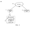
FIG. 2 is a block diagram depiction of the wireless communication system ofFIG. 1 , in accordance with multiple embodiments of the present invention. -
FIG. 3 is a logic flow diagram of functionality performed by a network in accordance with multiple embodiments of the present invention. -
FIG. 4 is a logic flow diagram of functionality performed by a remote unit in accordance with multiple embodiments of the present invention. -
FIG. 5 is a logic flow diagram of functionality performed by a network in accordance with multiple embodiments of the present invention. - Specific embodiments of the present invention are disclosed below with reference to
FIGs. 1-5 . Both the description and the illustrations have been drafted with the intent to enhance understanding. For example, the dimensions of some of the figure elements may be exaggerated relative to other elements, and well-known elements that are beneficial or even necessary to a commercially successful implementation may not be depicted so that a less obstructed and a more clear presentation of embodiments may be achieved. In addition, unless specifically indicated, the order and grouping of signaling is not a limitation of other embodiments that may lie within the scope of the claims. - Simplicity and clarity in both illustration and description are sought to effectively enable a person of skill in the art to make, use, and best practice the present invention in view of what is already known in the art. One of skill in the art will appreciate that various modifications and changes may be made to the specific embodiments described below without departing from the scope of the present invention. Thus, the specification and drawings are to be regarded as illustrative and exemplary rather than restrictive or all-encompassing, and all such modifications to the specific embodiments described below are intended to be included within the scope of the present invention.
- Various embodiments are described which may serve to improve spreading channel code selection in wireless technologies that employ two-stage ranging. For example, some of the embodiments enable a number of spreading codes to be reused at each network node, potentially increasing the number of codes available to each remote unit and thereby reducing the collision rate. Rather than simply selecting a spreading channel code randomly, remote units, select a spreading channel code based on one or more considerations such as at least one of pilot signal strength and remote unit location. Remote units may also base this selection of a spreading channel code on one or more additional considerations, i.e. at least one of a remote unit mobility level, and a priority class associated with the remote unit. Depending on the embodiment, network nodes can partition the spreading codes into groups and then assign link bandwidth to remote units based on the group associated with the code selected by that remote unit.
- The disclosed embodiments can be more fully understood with reference to
FIGs. 1-5 .FIGs. 1 and2 depict awireless communication system 100 in accordance with multiple embodiments of the present invention. At present, standards bodies such as OMA (Open Mobile Alliance), 3GPP (3rd Generation Partnership Project), 3GPP2 (3rd Generation Partnership Project 2) and IEEE (Institute of Electrical and Electronics Engineers) 802 are developing standards specifications for wireless telecommunications systems. (These groups may be contacted via http://www.openmobilealliance.com, http://www.3gpp.org/, http://www.3gpp2.com/ and http://www.ieee802.org/, respectively.)Communication system 100 represents a system having an architecture in accordance with one or more of the 3GPP2 technologies, suitably modified to implement the present invention. Alternative embodiments of the present invention may be implemented in communication systems that employ other or additional technologies such as, but not limited to, those described in the 3GPP specifications and/or those described in the IEEE's 802.xx specifications (e.g., 802.16). -
Communication system 100 is depicted in a very generalized manner, shown to comprisenetwork nodes network 130. Those skilled in the art will recognize thatFIGs. 1 and2 do not depict all of the network equipment necessary forsystem 100 to operate but only those system components and logical entities particularly relevant to the description of embodiments herein. For example, depending on the embodiment,network 130 may represent an IP (internet protocol) network or, in combination withnetwork nodes network nodes FIGs. 1 or2 . - In
FIG. 2 ,remote unit 101 andnetwork node 111 are shown communicating via technology-dependent,wireless interface 150. Remote units, or user equipment (UEs), may be thought of as mobile stations (MSs); however, remote units are not necessarily mobile nor able to move. In addition, remote unit / UE platforms are known to refer to a wide variety of consumer electronic platforms such as, but not limited to, mobile stations (MSs), access terminals (ATs), terminal equipment, mobile devices, gaming devices, personal computers, personal digital assistants (PDAs). In particular,remote unit 101 comprisesprocessing unit 105, andtransceiver 107. Depending on the embodiment,remote unit 101 may additionally comprise a keypad (not shown), a speaker (not shown), a microphone (not shown), and a display (not shown). Processing units, transceivers, keypads, speakers, microphones, and displays as used in UEs are all well-known in the art. - In general, components such as transceivers, keypads, speakers, microphones, and displays are well-known. For example, processing units are known to comprise basic components such as, but neither limited to nor necessarily requiring, microprocessors, microcontrollers, memory devices, application-specific integrated circuits (ASICs), and/or logic circuitry. Such components are typically adapted to implement algorithms and/or protocols that have been expressed using high-level design languages or descriptions, expressed using computer instructions, expressed using signaling flow diagrams, and/or expressed using logic flow diagrams.
- Thus, given a high-level description, an algorithm, a logic flow, a messaging / signaling flow, and/or a protocol specification, those skilled in the art are aware of the many design and development techniques available to implement a processing unit that performs the given logic. Therefore,
remote unit 101 represents a known device that has been adapted, in accordance with the description herein, to implement multiple embodiments of the present invention. - Furthermore, those skilled in the art will recognize that aspects of the present invention may be implemented in and across various physical components and none are necessarily limited to single platform implementations. For example, the network aspects may be implemented in or across one or more network devices, such as in
network node 111 or across one or more network nodes and/ornetwork 130. - Operation of embodiments in accordance with the present invention occurs substantially as follows.
Processing unit 105 ofremote unit 101 receives signaling fromnetwork node 111 viawireless interface 150 andtransceiver 107. In most embodiments, the received signaling is pilot information conveyed via a pilot channel ofnetwork node 111. In wireless technologies that employ spreading and two-stage ranging, prior art remote units randomly select a spreading channel code to use with their initial ranging signal. In contrast,processing unit 105 ofremote unit 101 selects a spreading channel code based on one or more considerations, depending on the particular embodiment. These considerations include at least one of the signal strength of the received signaling, and the current location of the remote unit. Remote units may also base this selection of a spreading channel code on one or more additional considerations, i.e. at least one of the current mobility level of the remote unit, and / or the current priority class associated with the remote unit. Having selected a spreading channel code,processing unit 105 then transmits, viatransceiver 107 andwireless interface 150, an initial access signal using the spreading channel code selected. This initial access signal may take the form of a ranging signal, for example, or other technology-dependent signaling required access the network node. - What type of spreading channel codes are selected and used also varies from one technology to the next. The spreading channel codes may be orthogonal or quasi-orthogonal, although they need not be either, such as the spreading codes specified in IEEE 802.16e. As another example, the spreading channel codes may be based on Chu sequences as described in
US2007165567, filed January 17, 2006 , entitled "PREAMBLE SEQUENCING FOR RANDOM ACCESS CHANNEL IN A COMMUNICATION SYSTEM". - In some embodiments,
network node 111 partitions the spreading channel codes that it makes available to remote units into code groups and transmits an indication of both the spreading channel codes available for use and the code group with which each is associated. This is information may be broadcast and received byremote unit 101 via a pilot channel ofnetwork node 111. Obviously, there are a great many ways to indicate the spreading channel codes and their associated code groups to remote units. The specific format of this signaling will, of course, depend upon how much information the remote units already have regarding the nature and identity of the code set used system-wide and used by the particular network node itself. - Thus,
remote unit 101 receives signaling that indicates which spreading channel codes may be used by the remote unit for accessingnetwork node 111 and the associated groupings of the codes. In these embodiments, then, processingunit 105 determines a particular code group from which to select a spreading channel code to use. Depending on the embodiment,remote unit 101 determines a particular code group based on one or more considerations. These considerations comprise a received signal strength (the pilot signal strength, e.g.) fromnetwork node 111 and the current location ofremote unit 101.Remote unit 101 may also determine the particular code group based on one or more additional considerations, i.e. at least one of the current mobility level ofremote unit 101, and / or a current priority class associated withremote unit 101. - This determination may in addition be guided by the remote unit characteristics that individual code groups are intended to target. For example, one code group may be targeted for remote units that are associated with a particular priority class, i.e. a particular level of service. This could allow codes to be "set aside" for users who have purchased a premium level service or users who are involved in responding to emergencies, for example.
- Code groups could also be targeted for remote units in a particular area. For example, a code group might target remote units inside (or outside)
region 125 aroundnetwork node 111. Or a code group may target an area of particular interest such as that around a stadium, convention center, highway, shopping center, auditorium, conference room, etc. Code groups could in addition target remote units having a particular level of mobility. For example, one code group may target low-mobility units while another targets high-mobility units. - A characteristic that individual code groups may be intended to target is remote unit received signal strength, this being of signaling from the network node such as pilot signaling that is received by the remote unit. (Signal strength is used throughout this description to generically refer to the various forms of signal measurement that are used such as signal quality measurements, measurements for CQI (channel quality indicator), and/or unique metrics derived from various combinations of both). One example of code groups targeting remote unit received signal strength would be for
network node 111 to target one code group for units that have a received signal strength above a particular threshold and another code group for units that have a received signal strength below the particular threshold. - In effect, then,
network node 111 could target one code group for coverage region 125 (roughly) and another for the remainder ofcoverage area 121. (Note that a similar effect could be achieved using remote unit location, as described above.) Partitioning the spreading channel codes into code groups that are targeted for particular coverage regions can enable greater code reuse than is believed available today. For example, the spreading channel codes of one or more code groups targetingwireless coverage region 125, for instance, can be reused by network nodes with wireless coverage areas adjacent tonetwork node 111. Thus, since interference is not a problem betweencoverage regions network nodes - Additionally or alternatively,
network node 111 may monitor a system loading level and partition the spreading channel codes into code groups based on the current system load. For example,network node 111 may partition the spreading channel codes into more code groups when the system loading level is greater than a loading threshold. Examples of system loading level indicators that may be used include the number of collisions per code/code group, the number of transmissions per code/code group (equivalently utilization of codes/code groups), recent changes in the number of users attached to the cell in different cell groups (predicting/anticipating a significant change in pattern), etc. The benefit sought by considering the level of system loading is that by partitioning more code groups and having the remote unit selecting the appropriate code group, the system can save capacity by using information from the remote unit indicating how large a resource assignment it needs. In other words, if there are only two groups, then the network will still end up doing a fair bit of over assignment of resources for mobiles which are very close to the network node, as the network may think that they are as far away as halfway out within the cell. However, by partitioning 10 different groups, then the network can know that the user who is very near the tower is within the closest 1/10 or so of the cell/sector and thus can use an even smaller assignment. The downside of breaking the codes into more groups is that of potentially creating more collisions within one group while another group is under-utilized. However, this can be addressed by dividing the unit among code groups in different time intervals. - Thus, depending on the embodiment,
remote unit 101 determines a particular code group based on one or more of the considerations of: a received signal strength fromnetwork node 111 and the current location ofremote unit 101.Remote unit 101 may also determine the particular code group based on one or more additional considerations, i.e. at least one of the current mobility level ofremote unit 101, and / or a current priority class associated withremote unit 101. As discussed above, this determination may be guided by the remote unit characteristics that individual code groups are intended to target.Network node 111 may also indicate toremote unit 101, in addition to the codes and the code groupings, what characteristics the code groups are intended to target. - Using this received information or some pre-defined information regarding the targeted characteristics of the code groups,
remote unit 101 determines a particular code group from which to select a spreading channel code. In some embodiments, processingunit 105 simply selects a spreading channel code randomly from the spreading channel codes associated with the determined group. Thus, the selection of a spreading channel code based on various considerations may be performed by determining a code group, based on the particular considerations, and then selecting, perhaps randomly, a spreading channel code from the determined code group. - A number of examples of remote unit characteristics for which code groups could be targeted was provided above. Thus,
remote unit 101 considers the applicable characteristics or combination of characteristics that the available code groups target to determine a code group from which to select a code. For example,remote unit 101 may determine to select from one code group because of the remote unit's current location (per GPS, e.g.). In another embodiment,remote unit 101 may determine to select from a particular code group because the pilot signal strength ofnetwork node 111 is greater than a threshold and, in this example, an additional consideration to be applied to the determination may be thatremote unit 101 currently has a low level of mobility. Another code group may be determined for selection in the case that the pilot signal strength is below the threshold. This is just one example of the many possible combinations of characteristics that code groups might target to effect a partitioning of the spreading codes. - Depending on the embodiment, however, remote units may not be locked into selecting a spreading channel code from the code group targeted by the applicable remote unit characteristics. For example,
remote unit 101 may determine the code group that applies to its current situation, select a code to use from that code group, and then determine that the code selected is being used by another device. In such a case,remote unit 101 may select another code from the determined code group or may select a code from another code group altogether. - Some other embodiment-specific aspects that may be incorporated into the embodiments already described follow. The spreading channel codes that are partitioned into groups, while unique as codes, may share a common modulation and coding type. Thus, when a remote unit, in this case, selects a spreading channel code, it is not selecting a level of redundancy or a type of modulation / data rate.
- In addition to selecting a spreading channel code, in some embodiments the remote unit will select the spreading channel code and a time period for using the spreading channel code. In other words, the remote unit selects a code-time combination (e.g., a code and a start time) from a group of code-time combinations. Thus, the available code-time combinations are partitioned into groups just as the codes alone would be, except that the same codes may be in different groups but associated with different time periods for use. Determination of a group of code-time combinations from which to select could occur as described herein for code groups.
- After
network node 111 receives an initial access signal fromremote unit 101 using the spreading channel code selected byremote unit 101,network node 111 may assign an amount of link bandwidth (forward and/or reverse link bandwidth) to the remote unit based on the code group of the spreading channel code used. For example, in a case in which the code group has been targeted for a level of signal strength of a signal received by the remote unit greater than a threshold and the remote unit uses a spreading channel code from that code group, the network node may assign a smaller amount of link bandwidth to the remote unit than would be otherwise assigned. Here, the network node may assume that the smaller amount of link bandwidth will be sufficient since the remote unit has signal strength greater than the threshold, as indicated by the spreading channel code the remote unit used. Potentially then, using this technique, less bandwidth may be used in certain situations, improving system capacity. -
FIG. 3 is a logic flow diagram of functionality performed by a network in accordance with multiple embodiments of the present invention.Logic flow 300 begins (301) with the network partitioning (303) a plurality of spreading channel codes into a plurality of code groups. The network then transmits (305) signaling that indicates the code groupings produced by the partitioning and receives an initial access signal from a remote unit using a spreading channel code from a code group of the plurality of code groups.Logic flow 300 then ends (309). -
FIG. 4 is a logic flow diagram of functionality performed by a remote unit in accordance with multiple embodiments of the present invention.Logic flow 400 begins (401) when a remote unit receives (403) signaling from a network node. The remote unit selects (405) a spreading channel code based on at least one characteristic from a group of a signal strength of the received signaling, a current location of the remote unit, a current mobility level of the remote unit, and a current priority class associated with the remote unit. The remote unit then transmits (407) an initial access signal using the spreading channel code.Logic flow 400 then ends (409). -
FIG. 5 is a logic flow diagram of functionality performed by a network in accordance with multiple embodiments of the present invention.Logic flow 500 begins (501) with the network partitioning (503) a plurality of spreading channel codes into a plurality of code groups. The network then receives (505) an initial access signal from a remote unit using a spreading channel code from a code group of the plurality of code groups. In response, the network assigns (507) an amount of link bandwidth to the remote unit based on the code group of the spreading channel code used by the remote unit.Logic flow 500 then ends (509). - Benefits, other advantages, and solutions to problems have been described above with regard to specific embodiments of the present invention. However, the benefits, advantages, solutions to problems, and any element(s) that may cause or result in such benefits, advantages, or solutions, or cause such benefits, advantages, or solutions to become more pronounced are not to be construed as a critical, required, or essential feature or element of any or all the claims.
- As used herein and in the appended claims, the term "comprises," "comprising," or any other variation thereof is intended to refer to a non-exclusive inclusion, such that a process, method, article of manufacture, or apparatus that comprises a list of elements does not include only those elements in the list, but may include other elements not expressly listed or inherent to such process, method, article of manufacture, or apparatus. The terms a or an, as used herein, are defined as one or more than one. The term plurality, as used herein, is defined as two or more than two. The term another, as used herein, is defined as at least a second or more. The terms including and/or having, as used herein, are defined as comprising (i.e., open language). The term coupled, as used herein, is defined as connected, although not necessarily directly, and not necessarily mechanically. Terminology derived from the word "indicating" (e.g., "indicates" and "indication") are intended to encompass all the various techniques available for communicating or referencing the object being indicated. Some, but not all examples of techniques available for communicating or referencing the object being indicated include the conveyance of the object being indicated, the conveyance of an identifier of the object being indicated, the conveyance of information used to generate the object being indicated, the conveyance of some part or portion of the object being indicated, the conveyance of some derivation of the object being indicated, and the conveyance of some symbol representing the object being indicated. The terms program, computer program, and computer instructions, as used herein, are defined as a sequence of instructions designed for execution on a computer system. This sequence of instructions may include, but is not limited to, a subroutine, a function, a procedure, an object method, an object implementation, an executable application, an applet, a servlet, a shared library/dynamic load library, a source code, an object code and/or an assembly code.
Claims (15)
- A method (400) for spreading channel code selection, the method (400) comprising:receiving (403), by a remote unit (101), signaling from a network node (111) that indicates a plurality of spreading channel codes which may be used by the remote unit (101) for accessing the network node (111) and, for each spreading channel code of the plurality of spreading channel codes, a code group with which the spreading channel code is associated;determining, by the remote unit (101), a particular code group from among the code groups associated with the plurality of spreading channel codes based on at least one of:a signal strength of the received signaling; anda current location of the remote unit (101);selecting (405), by the remote unit (101), a spreading channel code from the determined code group; andtransmitting (407), by the remote unit (101) to the network node (111), an initial access signal using the selected spreading channel code.
- The method (400) of claim 1, wherein the initial access signal comprises a ranging signal.
- The method (400) of claim 1 or claim 2, wherein a common modulation and coding type is associated with each of the code groups.
- The method (400) of any previous claim,
wherein selecting (405), by the remote unit (101), the spreading channel code comprises selecting by the remote unit (101) the spreading channel code and a time period for using the spreading channel code, and
wherein transmitting (407) by the remote unit (101) the initial access signal using the spreading channel code comprises transmitting by the remote unit (101) the initial access signal using the spreading channel code during the time period. - The method (400) of any of claims 1-3, wherein selecting (405) by the remote unit (101) the spreading channel code comprises selecting the spreading channel code and a time period for using the spreading channel code.
- The method (400) of claim 5, wherein selecting (405) by the remote unit (101) the spreading channel code and the time period for using the spreading channel code comprises selecting by the remote unit (101) a code-time combination from a determined group of code-time combinations,
wherein the determined group is one of a plurality of groups of code-time combinations that may be used by the remote unit (101) for accessing the network node (111), and
wherein the determined group is determined based on at least one of:a signal strength of the received signaling, anda current location of the remote unit (101). - The method (400) of claim 1, further comprising:partitioning (503) the plurality of spreading channel codes into the plurality of code groups that a remote unit (101) may use for accessing a network node (111);transmitting by the network node (111) signaling that indicates the code groups produced by the partitioning; andreceiving (505) by the network node (111) the initial access signal from a remote unit (101) using a spreading channel code selected from a determined code group of the plurality of code groups.
- The method (400) of any previous claim, further comprising:reusing, by at least one adjacent network node, spreading channel codes from at least one code group of the plurality of code groups, wherein the at least one adjacent network node comprises at least one network node (112) having a wireless coverage area (126) adjacent to the network node (111).
- The method (400) of any of claims 1-6, further comprising partitioning (503), by the network node (111), a plurality of spreading channel codes into a plurality of code groups that a remote unit (101) may use for accessing a network node (111).
- The method (400) of claim 9, wherein partitioning a plurality of spreading channel codes into a plurality of code groups comprises:determining whether a system loading level is greater than a loading threshold; andpartitioning the plurality of spreading channel codes into a plurality of code groups such that a greater number of code groups are formed when the system loading level is greater than the loading threshold than are formed when the system loading level is not greater than the loading threshold.
- The method (400) of any previous claim, further comprising:assigning (507) an amount of link bandwidth to the remote unit (101) based on the code group of the spreading channel code used by the remote unit (101);wherein, when the code group is associated with a level of signal strength of a signal received by the remote unit (101) from the network node (111) that is greater than a signal strength threshold, a smaller amount of link bandwidth is assigned to the remote unit (101) than would otherwise be assigned.
- The method (400) of any previous claim, wherein the determined code group is determined based on at least one further characteristic from a group of:a current mobility level of the remote unit (101);a current priority class associated with the remote unit (101).
- A remote unit (101) comprising:a transceiver (107); anda processing unit (105), communicatively coupled to the transceiver (107), and:adapted to receive (403), via the transceiver (107), signaling from a network node (111) that indicates a plurality of spreading channel codes which may be used by the remote unit (101) for accessing the network node (111) and, for each spreading channel code of the plurality of spreading channel codes, a code group with which the spreading channel code is associated;adapted to determine a particular code group from among the code groups associated with the plurality of spreading channel codes based on at least one of:a signal strength of the received signaling; anda current location of the remote unit (101);adapted to select (405) a spreading channel code from the determined code group; andadapted to transmit (407), via the transceiver (107) to the network node (111), an initial access signal using the selected spreading channel code.
- The remote unit (101) of claim 13, wherein the remote unit (101) is further operable to determine the code group based on at least one further characteristic from a group of:a current mobility level of the remote unit (101);a current priority class associated with the remote unit (101).
- The remote unit (101) of claim 13 or claim 14, wherein the remote unit is operable in accordance with the 802.16 standard.
Applications Claiming Priority (3)
| Application Number | Priority Date | Filing Date | Title |
|---|---|---|---|
| US78152706P | 2006-03-10 | 2006-03-10 | |
| US11/624,428 US8009637B2 (en) | 2006-03-10 | 2007-01-18 | Method and apparatus for spreading channel code selection |
| PCT/US2007/062377 WO2007106643A2 (en) | 2006-03-10 | 2007-02-19 | Method and apparatus for spreading channel code selection |
Publications (3)
| Publication Number | Publication Date |
|---|---|
| EP1997243A2 EP1997243A2 (en) | 2008-12-03 |
| EP1997243A4 EP1997243A4 (en) | 2011-09-14 |
| EP1997243B1 true EP1997243B1 (en) | 2014-10-29 |
Family
ID=38478900
Family Applications (1)
| Application Number | Title | Priority Date | Filing Date |
|---|---|---|---|
| EP07757173.5A Active EP1997243B1 (en) | 2006-03-10 | 2007-02-19 | Method and apparatus for spreading channel code selection |
Country Status (6)
| Country | Link |
|---|---|
| US (1) | US8009637B2 (en) |
| EP (1) | EP1997243B1 (en) |
| JP (1) | JP2009528724A (en) |
| KR (1) | KR101004947B1 (en) |
| CN (1) | CN101411090B (en) |
| WO (1) | WO2007106643A2 (en) |
Families Citing this family (9)
| Publication number | Priority date | Publication date | Assignee | Title |
|---|---|---|---|---|
| HUE050594T2 (en) | 2006-03-20 | 2020-12-28 | Optis Wireless Technology Llc | Radio communication mobile station apparatus and radio communication method |
| US8861549B2 (en) * | 2007-11-05 | 2014-10-14 | Telefonaktiebolaget Lm Ericsson (Publ) | Multiple compatible OFDM systems with different bandwidths |
| US20090161616A1 (en) * | 2007-11-07 | 2009-06-25 | Telefonaktiebolaget Lm Ericsson (Publ) | Ranging procedure identification of enhanced wireless terminal |
| US8050238B2 (en) * | 2007-12-31 | 2011-11-01 | Motorola Mobility, Inc. | Method and apparatus for improving network access through multi-stage signaling |
| KR101461371B1 (en) * | 2008-09-02 | 2014-11-13 | 알까뗄 루슨트 | Method and device for requesting and processing uplink resource allocation in radio access network |
| US8737362B2 (en) * | 2009-12-30 | 2014-05-27 | The American University In Cairo | Methods, systems, and computer readable media for interference-minimizing code assignment and system parameter selection for code division multiple access (CDMA) networks |
| US9241298B2 (en) * | 2011-11-18 | 2016-01-19 | Qualcomm Incorporated | Devices and methods for facilitating access probe sequences |
| EP2908593B1 (en) | 2014-02-12 | 2018-08-01 | Alcatel Lucent | Apparatuses, methods and computer programs for a base station transceiver and a mobile transceiver |
| WO2019173961A1 (en) * | 2018-03-13 | 2019-09-19 | Qualcomm Incorporated | Sequence selection techniques for non-orthogonal multiple access (noma) |
Family Cites Families (28)
| Publication number | Priority date | Publication date | Assignee | Title |
|---|---|---|---|---|
| US6359874B1 (en) * | 1998-05-21 | 2002-03-19 | Ericsson Inc. | Partially block-interleaved CDMA coding and decoding |
| FI105741B (en) * | 1998-02-12 | 2000-09-29 | Nokia Networks Oy | Communication method and radio system |
| EP2306662B1 (en) * | 1998-10-05 | 2014-08-27 | Sony Deutschland Gmbh | Random access channel prioritization scheme |
| DK1142149T3 (en) * | 1998-12-14 | 2004-07-26 | Interdigital Tech Corp | Random access channel preamble detection |
| US6654364B1 (en) * | 1999-02-16 | 2003-11-25 | Sprint Spectrum L.P. | Cellular/PCS CDMA system with increased sector capacity |
| US6567482B1 (en) * | 1999-03-05 | 2003-05-20 | Telefonaktiebolaget Lm Ericsson (Publ) | Method and apparatus for efficient synchronization in spread spectrum communications |
| US6185423B1 (en) * | 1999-05-28 | 2001-02-06 | 3Com Corporation | Method and apparatus for selecting a communication channel in a communication network |
| US6522658B1 (en) * | 1999-06-07 | 2003-02-18 | Trw Inc. | Method for discriminating and routing data packets based on quality-of-service requirements |
| US6324209B1 (en) * | 2000-02-28 | 2001-11-27 | Golden Bridge Technology Inc. | Multi-channel spread spectrum system |
| US6743395B2 (en) * | 2000-03-22 | 2004-06-01 | Ebara Corporation | Composite metallic ultrafine particles and process for producing the same |
| EP1212853B1 (en) * | 2000-06-02 | 2005-08-31 | Samsung Electronics Co., Ltd. | Method for selecting rach in a cdma mobile communication system |
| US6388615B1 (en) | 2000-06-06 | 2002-05-14 | Hughes Electronics Corporation | Micro cell architecture for mobile user tracking communication system |
| US7558568B2 (en) | 2003-07-28 | 2009-07-07 | Atc Technologies, Llc | Systems and methods for modifying antenna radiation patterns of peripheral base stations of a terrestrial network to allow reduced interference |
| US7133353B2 (en) * | 2001-01-08 | 2006-11-07 | Telefonaktiebolaget Lm Ericsson (Publ) | CDMA system using quasi-orthogonal codes |
| US6567393B2 (en) * | 2001-02-27 | 2003-05-20 | Nokia Networks Oy | Dynamic reselection of CDMA spreading codes |
| US6996056B2 (en) | 2001-05-31 | 2006-02-07 | Nortel Networks Limited | Method and apparatus for orthogonal code management in CDMA systems using smart antenna technology |
| US7088673B2 (en) * | 2001-11-02 | 2006-08-08 | Intel Corporation | Dynamically-scalable system and method for multiple user access utilzing multi-bit and multi-code orthogonal multiplexing |
| US6754169B2 (en) * | 2001-12-13 | 2004-06-22 | Motorola, Inc. | Method and system of operation for a variable transmission mode multi-carrier communication system |
| US20040071115A1 (en) * | 2002-10-11 | 2004-04-15 | Mark Earnshaw | Intelligent uplink SCDMA scheduling incorporating polarization and/or spatial information to determine SCDMA code set assignment |
| WO2004077714A1 (en) * | 2003-02-26 | 2004-09-10 | Linkair Communications,Inc. | Low correlation/ zero correlation spread spectrum code sets coding and the method of its application |
| US7554965B2 (en) * | 2003-05-21 | 2009-06-30 | Broadcom Corporation | UWB (Ultra Wide Band) waveform design to minimize narrowband interference |
| US7577120B2 (en) * | 2003-07-02 | 2009-08-18 | Alcatel-Lucent Usa Inc. | Allocation of power and channelization codes for data transfers |
| US7450556B2 (en) * | 2003-07-10 | 2008-11-11 | Via Telecom Co., Ltd. | Method and apparatus estimating cell interference and noise for CDMA packet data channels |
| KR100651541B1 (en) * | 2003-07-30 | 2006-11-28 | 삼성전자주식회사 | Method for ranging in mobile communication system using orthogonal frequency division multiple access scheme |
| KR20050015119A (en) | 2003-08-04 | 2005-02-21 | 삼성전자주식회사 | Apparatus for modulation ranging signals in broadband wireless access communication system and method thereof |
| US9137822B2 (en) | 2004-07-21 | 2015-09-15 | Qualcomm Incorporated | Efficient signaling over access channel |
| EP1869909A4 (en) * | 2005-03-07 | 2012-08-15 | Texas Instruments Inc | System and method for ranging |
| US8000305B2 (en) | 2006-01-17 | 2011-08-16 | Motorola Mobility, Inc. | Preamble sequencing for random access channel in a communication system |
-
2007
- 2007-01-18 US US11/624,428 patent/US8009637B2/en active Active
- 2007-02-19 EP EP07757173.5A patent/EP1997243B1/en active Active
- 2007-02-19 CN CN200780011205.8A patent/CN101411090B/en not_active Expired - Fee Related
- 2007-02-19 JP JP2008556506A patent/JP2009528724A/en active Pending
- 2007-02-19 WO PCT/US2007/062377 patent/WO2007106643A2/en active Application Filing
- 2007-02-19 KR KR1020087022002A patent/KR101004947B1/en active IP Right Grant
Also Published As
| Publication number | Publication date |
|---|---|
| US20070211787A1 (en) | 2007-09-13 |
| CN101411090A (en) | 2009-04-15 |
| KR101004947B1 (en) | 2010-12-28 |
| KR20080100253A (en) | 2008-11-14 |
| US8009637B2 (en) | 2011-08-30 |
| WO2007106643A3 (en) | 2008-05-29 |
| EP1997243A2 (en) | 2008-12-03 |
| JP2009528724A (en) | 2009-08-06 |
| WO2007106643A2 (en) | 2007-09-20 |
| CN101411090B (en) | 2014-04-23 |
| EP1997243A4 (en) | 2011-09-14 |
Similar Documents
| Publication | Publication Date | Title |
|---|---|---|
| EP1997243B1 (en) | Method and apparatus for spreading channel code selection | |
| KR102505734B1 (en) | Method and Apparatus for Performing Contention Based Random Access in Carrier Frequency | |
| US8611300B2 (en) | Method and apparatus for conveying control channel information in OFDMA system | |
| US20070253379A1 (en) | Method and apparatus for uplink allocation placement in an uplink frame | |
| JP6772256B2 (en) | Broadcast ranging message for WLAN RTT measurement | |
| TWI710276B (en) | Method for d2d communication, d2d device, and base station | |
| CN107409313B (en) | Discovery signal transmission method and device and communication system | |
| CN108667580B (en) | Reference signal sending method, terminal equipment and access network equipment | |
| KR20090049971A (en) | Method for random access based on priority | |
| JP2019512905A (en) | Method and apparatus for determining transmission resources of device-to-device communication | |
| CN108781352B (en) | User Equipment (UE), base station, method performed by User Equipment (UE) and method performed by base station | |
| JP2019519955A (en) | Communication method, network equipment and terminal equipment | |
| KR20190075998A (en) | Method of switching communication mode, terminal equipment and network equipment | |
| US8050238B2 (en) | Method and apparatus for improving network access through multi-stage signaling | |
| CN108605263B (en) | Device-to-device based communication method and terminal | |
| CN111726770B (en) | Communication method and device thereof | |
| JP2018074192A (en) | Radio communication system, base station device, radio communication control device and radio communication control method | |
| US10743292B2 (en) | Method and apparatus for resource allocation | |
| CN109417775B (en) | End-to-end communication method, terminal and base station | |
| US11882429B2 (en) | Uplink resource determination apparatus, method and computer program | |
| EP1754388B1 (en) | Cell update message indicating whether user data or control data is transmitted uplink, and respective procedures for handling these two types of data | |
| EP3764716B1 (en) | Method and device for determining resources | |
| CN116326068A (en) | Adaptive application of orthogonal cover codes to resource elements of a wireless communication system | |
| CN113747463A (en) | Perception result processing method and device | |
| CN111642016A (en) | Link reconfiguration processing method and related product |
Legal Events
| Date | Code | Title | Description |
|---|---|---|---|
| PUAI | Public reference made under article 153(3) epc to a published international application that has entered the european phase |
Free format text: ORIGINAL CODE: 0009012 |
|
| AK | Designated contracting states |
Kind code of ref document: A2 Designated state(s): AT BE BG CH CY CZ DE DK EE ES FI FR GB GR HU IE IS IT LI LT LU LV MC NL PL PT RO SE SI SK TR |
|
| AX | Request for extension of the european patent |
Extension state: AL BA HR MK RS |
|
| 17P | Request for examination filed |
Effective date: 20081201 |
|
| RBV | Designated contracting states (corrected) |
Designated state(s): AT BE BG CH CY CZ DE DK EE ES FI FR GB GR HU IE IS IT LI LT LU LV MC NL PL PT RO SE SI SK TR |
|
| RAP1 | Party data changed (applicant data changed or rights of an application transferred) |
Owner name: MOTOROLA SOLUTIONS, INC. |
|
| A4 | Supplementary search report drawn up and despatched |
Effective date: 20110817 |
|
| RIC1 | Information provided on ipc code assigned before grant |
Ipc: H04L 5/00 20060101ALI20110810BHEP Ipc: H04B 7/216 20060101AFI20110810BHEP |
|
| DAX | Request for extension of the european patent (deleted) | ||
| 17Q | First examination report despatched |
Effective date: 20130201 |
|
| REG | Reference to a national code |
Ref country code: DE Ref legal event code: R079 Ref document number: 602007039042 Country of ref document: DE Free format text: PREVIOUS MAIN CLASS: H04B0007216000 Ipc: H04J0013160000 |
|
| RIC1 | Information provided on ipc code assigned before grant |
Ipc: H04J 13/16 20110101AFI20140506BHEP Ipc: H04W 74/08 20090101ALI20140506BHEP |
|
| GRAP | Despatch of communication of intention to grant a patent |
Free format text: ORIGINAL CODE: EPIDOSNIGR1 |
|
| INTG | Intention to grant announced |
Effective date: 20140613 |
|
| GRAS | Grant fee paid |
Free format text: ORIGINAL CODE: EPIDOSNIGR3 |
|
| GRAA | (expected) grant |
Free format text: ORIGINAL CODE: 0009210 |
|
| AK | Designated contracting states |
Kind code of ref document: B1 Designated state(s): AT BE BG CH CY CZ DE DK EE ES FI FR GB GR HU IE IS IT LI LT LU LV MC NL PL PT RO SE SI SK TR |
|
| REG | Reference to a national code |
Ref country code: GB Ref legal event code: FG4D |
|
| REG | Reference to a national code |
Ref country code: CH Ref legal event code: EP |
|
| REG | Reference to a national code |
Ref country code: AT Ref legal event code: REF Ref document number: 694002 Country of ref document: AT Kind code of ref document: T Effective date: 20141115 |
|
| REG | Reference to a national code |
Ref country code: IE Ref legal event code: FG4D |
|
| REG | Reference to a national code |
Ref country code: DE Ref legal event code: R096 Ref document number: 602007039042 Country of ref document: DE Effective date: 20141211 |
|
| REG | Reference to a national code |
Ref country code: AT Ref legal event code: MK05 Ref document number: 694002 Country of ref document: AT Kind code of ref document: T Effective date: 20141029 |
|
| REG | Reference to a national code |
Ref country code: NL Ref legal event code: VDEP Effective date: 20141029 |
|
| REG | Reference to a national code |
Ref country code: LT Ref legal event code: MG4D |
|
| PG25 | Lapsed in a contracting state [announced via postgrant information from national office to epo] |
Ref country code: IS Free format text: LAPSE BECAUSE OF FAILURE TO SUBMIT A TRANSLATION OF THE DESCRIPTION OR TO PAY THE FEE WITHIN THE PRESCRIBED TIME-LIMIT Effective date: 20150228 Ref country code: ES Free format text: LAPSE BECAUSE OF FAILURE TO SUBMIT A TRANSLATION OF THE DESCRIPTION OR TO PAY THE FEE WITHIN THE PRESCRIBED TIME-LIMIT Effective date: 20141029 Ref country code: PT Free format text: LAPSE BECAUSE OF FAILURE TO SUBMIT A TRANSLATION OF THE DESCRIPTION OR TO PAY THE FEE WITHIN THE PRESCRIBED TIME-LIMIT Effective date: 20150302 Ref country code: LT Free format text: LAPSE BECAUSE OF FAILURE TO SUBMIT A TRANSLATION OF THE DESCRIPTION OR TO PAY THE FEE WITHIN THE PRESCRIBED TIME-LIMIT Effective date: 20141029 Ref country code: NL Free format text: LAPSE BECAUSE OF FAILURE TO SUBMIT A TRANSLATION OF THE DESCRIPTION OR TO PAY THE FEE WITHIN THE PRESCRIBED TIME-LIMIT Effective date: 20141029 Ref country code: FI Free format text: LAPSE BECAUSE OF FAILURE TO SUBMIT A TRANSLATION OF THE DESCRIPTION OR TO PAY THE FEE WITHIN THE PRESCRIBED TIME-LIMIT Effective date: 20141029 |
|
| PG25 | Lapsed in a contracting state [announced via postgrant information from national office to epo] |
Ref country code: PL Free format text: LAPSE BECAUSE OF FAILURE TO SUBMIT A TRANSLATION OF THE DESCRIPTION OR TO PAY THE FEE WITHIN THE PRESCRIBED TIME-LIMIT Effective date: 20141029 Ref country code: SE Free format text: LAPSE BECAUSE OF FAILURE TO SUBMIT A TRANSLATION OF THE DESCRIPTION OR TO PAY THE FEE WITHIN THE PRESCRIBED TIME-LIMIT Effective date: 20141029 Ref country code: AT Free format text: LAPSE BECAUSE OF FAILURE TO SUBMIT A TRANSLATION OF THE DESCRIPTION OR TO PAY THE FEE WITHIN THE PRESCRIBED TIME-LIMIT Effective date: 20141029 Ref country code: CY Free format text: LAPSE BECAUSE OF FAILURE TO SUBMIT A TRANSLATION OF THE DESCRIPTION OR TO PAY THE FEE WITHIN THE PRESCRIBED TIME-LIMIT Effective date: 20141029 Ref country code: GR Free format text: LAPSE BECAUSE OF FAILURE TO SUBMIT A TRANSLATION OF THE DESCRIPTION OR TO PAY THE FEE WITHIN THE PRESCRIBED TIME-LIMIT Effective date: 20150130 Ref country code: LV Free format text: LAPSE BECAUSE OF FAILURE TO SUBMIT A TRANSLATION OF THE DESCRIPTION OR TO PAY THE FEE WITHIN THE PRESCRIBED TIME-LIMIT Effective date: 20141029 |
|
| REG | Reference to a national code |
Ref country code: DE Ref legal event code: R097 Ref document number: 602007039042 Country of ref document: DE |
|
| PG25 | Lapsed in a contracting state [announced via postgrant information from national office to epo] |
Ref country code: CZ Free format text: LAPSE BECAUSE OF FAILURE TO SUBMIT A TRANSLATION OF THE DESCRIPTION OR TO PAY THE FEE WITHIN THE PRESCRIBED TIME-LIMIT Effective date: 20141029 Ref country code: EE Free format text: LAPSE BECAUSE OF FAILURE TO SUBMIT A TRANSLATION OF THE DESCRIPTION OR TO PAY THE FEE WITHIN THE PRESCRIBED TIME-LIMIT Effective date: 20141029 Ref country code: SK Free format text: LAPSE BECAUSE OF FAILURE TO SUBMIT A TRANSLATION OF THE DESCRIPTION OR TO PAY THE FEE WITHIN THE PRESCRIBED TIME-LIMIT Effective date: 20141029 Ref country code: DK Free format text: LAPSE BECAUSE OF FAILURE TO SUBMIT A TRANSLATION OF THE DESCRIPTION OR TO PAY THE FEE WITHIN THE PRESCRIBED TIME-LIMIT Effective date: 20141029 Ref country code: RO Free format text: LAPSE BECAUSE OF FAILURE TO SUBMIT A TRANSLATION OF THE DESCRIPTION OR TO PAY THE FEE WITHIN THE PRESCRIBED TIME-LIMIT Effective date: 20141029 |
|
| PG25 | Lapsed in a contracting state [announced via postgrant information from national office to epo] |
Ref country code: IT Free format text: LAPSE BECAUSE OF FAILURE TO SUBMIT A TRANSLATION OF THE DESCRIPTION OR TO PAY THE FEE WITHIN THE PRESCRIBED TIME-LIMIT Effective date: 20141029 |
|
| REG | Reference to a national code |
Ref country code: DE Ref legal event code: R119 Ref document number: 602007039042 Country of ref document: DE |
|
| PLBE | No opposition filed within time limit |
Free format text: ORIGINAL CODE: 0009261 |
|
| STAA | Information on the status of an ep patent application or granted ep patent |
Free format text: STATUS: NO OPPOSITION FILED WITHIN TIME LIMIT |
|
| PG25 | Lapsed in a contracting state [announced via postgrant information from national office to epo] |
Ref country code: LU Free format text: LAPSE BECAUSE OF FAILURE TO SUBMIT A TRANSLATION OF THE DESCRIPTION OR TO PAY THE FEE WITHIN THE PRESCRIBED TIME-LIMIT Effective date: 20150219 |
|
| REG | Reference to a national code |
Ref country code: CH Ref legal event code: PL |
|
| 26N | No opposition filed |
Effective date: 20150730 |
|
| PG25 | Lapsed in a contracting state [announced via postgrant information from national office to epo] |
Ref country code: CH Free format text: LAPSE BECAUSE OF NON-PAYMENT OF DUE FEES Effective date: 20150228 Ref country code: MC Free format text: LAPSE BECAUSE OF FAILURE TO SUBMIT A TRANSLATION OF THE DESCRIPTION OR TO PAY THE FEE WITHIN THE PRESCRIBED TIME-LIMIT Effective date: 20141029 Ref country code: LI Free format text: LAPSE BECAUSE OF NON-PAYMENT OF DUE FEES Effective date: 20150228 |
|
| REG | Reference to a national code |
Ref country code: IE Ref legal event code: MM4A |
|
| REG | Reference to a national code |
Ref country code: FR Ref legal event code: ST Effective date: 20151030 |
|
| PG25 | Lapsed in a contracting state [announced via postgrant information from national office to epo] |
Ref country code: DE Free format text: LAPSE BECAUSE OF NON-PAYMENT OF DUE FEES Effective date: 20150901 Ref country code: IE Free format text: LAPSE BECAUSE OF NON-PAYMENT OF DUE FEES Effective date: 20150219 |
|
| PG25 | Lapsed in a contracting state [announced via postgrant information from national office to epo] |
Ref country code: FR Free format text: LAPSE BECAUSE OF NON-PAYMENT OF DUE FEES Effective date: 20150302 Ref country code: SI Free format text: LAPSE BECAUSE OF FAILURE TO SUBMIT A TRANSLATION OF THE DESCRIPTION OR TO PAY THE FEE WITHIN THE PRESCRIBED TIME-LIMIT Effective date: 20141029 |
|
| PG25 | Lapsed in a contracting state [announced via postgrant information from national office to epo] |
Ref country code: HU Free format text: LAPSE BECAUSE OF FAILURE TO SUBMIT A TRANSLATION OF THE DESCRIPTION OR TO PAY THE FEE WITHIN THE PRESCRIBED TIME-LIMIT; INVALID AB INITIO Effective date: 20070219 Ref country code: BG Free format text: LAPSE BECAUSE OF FAILURE TO SUBMIT A TRANSLATION OF THE DESCRIPTION OR TO PAY THE FEE WITHIN THE PRESCRIBED TIME-LIMIT Effective date: 20141029 |
|
| PG25 | Lapsed in a contracting state [announced via postgrant information from national office to epo] |
Ref country code: TR Free format text: LAPSE BECAUSE OF FAILURE TO SUBMIT A TRANSLATION OF THE DESCRIPTION OR TO PAY THE FEE WITHIN THE PRESCRIBED TIME-LIMIT Effective date: 20141029 |
|
| PG25 | Lapsed in a contracting state [announced via postgrant information from national office to epo] |
Ref country code: BE Free format text: LAPSE BECAUSE OF FAILURE TO SUBMIT A TRANSLATION OF THE DESCRIPTION OR TO PAY THE FEE WITHIN THE PRESCRIBED TIME-LIMIT Effective date: 20141029 |
|
| P01 | Opt-out of the competence of the unified patent court (upc) registered |
Effective date: 20230523 |
|
| PGFP | Annual fee paid to national office [announced via postgrant information from national office to epo] |
Ref country code: GB Payment date: 20240123 Year of fee payment: 18 |